EP3604105A1 - A bicycle with an electric motor and a drive unit of the bicycle - Google Patents
A bicycle with an electric motor and a drive unit of the bicycle Download PDFInfo
- Publication number
- EP3604105A1 EP3604105A1 EP19188735.5A EP19188735A EP3604105A1 EP 3604105 A1 EP3604105 A1 EP 3604105A1 EP 19188735 A EP19188735 A EP 19188735A EP 3604105 A1 EP3604105 A1 EP 3604105A1
- Authority
- EP
- European Patent Office
- Prior art keywords
- shaft
- drive unit
- transmission shaft
- rear hub
- transmission
- Prior art date
- Legal status (The legal status is an assumption and is not a legal conclusion. Google has not performed a legal analysis and makes no representation as to the accuracy of the status listed.)
- Granted
Links
Images



Classifications
-
- B—PERFORMING OPERATIONS; TRANSPORTING
- B62—LAND VEHICLES FOR TRAVELLING OTHERWISE THAN ON RAILS
- B62M—RIDER PROPULSION OF WHEELED VEHICLES OR SLEDGES; POWERED PROPULSION OF SLEDGES OR SINGLE-TRACK CYCLES; TRANSMISSIONS SPECIALLY ADAPTED FOR SUCH VEHICLES
- B62M6/00—Rider propulsion of wheeled vehicles with additional source of power, e.g. combustion engine or electric motor
- B62M6/40—Rider propelled cycles with auxiliary electric motor
- B62M6/60—Rider propelled cycles with auxiliary electric motor power-driven at axle parts
- B62M6/65—Rider propelled cycles with auxiliary electric motor power-driven at axle parts with axle and driving shaft arranged coaxially
-
- B—PERFORMING OPERATIONS; TRANSPORTING
- B62—LAND VEHICLES FOR TRAVELLING OTHERWISE THAN ON RAILS
- B62M—RIDER PROPULSION OF WHEELED VEHICLES OR SLEDGES; POWERED PROPULSION OF SLEDGES OR SINGLE-TRACK CYCLES; TRANSMISSIONS SPECIALLY ADAPTED FOR SUCH VEHICLES
- B62M6/00—Rider propulsion of wheeled vehicles with additional source of power, e.g. combustion engine or electric motor
- B62M6/40—Rider propelled cycles with auxiliary electric motor
- B62M6/45—Control or actuating devices therefor
- B62M6/50—Control or actuating devices therefor characterised by detectors or sensors, or arrangement thereof
-
- B—PERFORMING OPERATIONS; TRANSPORTING
- B62—LAND VEHICLES FOR TRAVELLING OTHERWISE THAN ON RAILS
- B62M—RIDER PROPULSION OF WHEELED VEHICLES OR SLEDGES; POWERED PROPULSION OF SLEDGES OR SINGLE-TRACK CYCLES; TRANSMISSIONS SPECIALLY ADAPTED FOR SUCH VEHICLES
- B62M17/00—Transmissions characterised by use of rotary shaft, e.g. cardan shaft
-
- B—PERFORMING OPERATIONS; TRANSPORTING
- B62—LAND VEHICLES FOR TRAVELLING OTHERWISE THAN ON RAILS
- B62M—RIDER PROPULSION OF WHEELED VEHICLES OR SLEDGES; POWERED PROPULSION OF SLEDGES OR SINGLE-TRACK CYCLES; TRANSMISSIONS SPECIALLY ADAPTED FOR SUCH VEHICLES
- B62M6/00—Rider propulsion of wheeled vehicles with additional source of power, e.g. combustion engine or electric motor
- B62M6/80—Accessories, e.g. power sources; Arrangements thereof
-
- B—PERFORMING OPERATIONS; TRANSPORTING
- B62—LAND VEHICLES FOR TRAVELLING OTHERWISE THAN ON RAILS
- B62M—RIDER PROPULSION OF WHEELED VEHICLES OR SLEDGES; POWERED PROPULSION OF SLEDGES OR SINGLE-TRACK CYCLES; TRANSMISSIONS SPECIALLY ADAPTED FOR SUCH VEHICLES
- B62M9/00—Transmissions characterised by use of an endless chain, belt, or the like
- B62M9/04—Transmissions characterised by use of an endless chain, belt, or the like of changeable ratio
- B62M9/06—Transmissions characterised by use of an endless chain, belt, or the like of changeable ratio using a single chain, belt, or the like
Definitions
- the present invention relates to a bicycle with an electric motor and a drive unit of the bicycle.
- JP2014-240267A discloses a bicycle having a crank, to which pedals are attached, and an electric motor, and capable of being driven by human power and an electric motor.
- the electric motor is disposed in the rear hub, and the rotor of the electric motor and the rear hub are fixed to each other so as to integrally rotate.
- a sprocket is disposed on the rear wheel axle, and coupled to the crank through the chain. The sprocket and the rear hub are also fixed to each other so as to integrally rotate.
- the opposite ends of the rear wheel axle in the lateral direction are supported by the rear arms.
- the rear arms are disposed right and left of the rear wheel. As such, the rear arms may obstruct the maintenance operation of the electric motor.
- One of the objects of the present disclosure is to improve workability of maintenance operation of a bicycle and a drive unit capable of being driven by human power and an electric motor.
- FIG. 1 arrows Y1 and Y2 respectively indicate forward and rearward directions, and arrows Z1 and Z2 respectively indicate upward and downward directions.
- FIG. 5 arrows X1 and X2 respectively indicate rightward and leftward directions, and a direction indicated by arrows X1-X2 is referred to as a left-right direction or an axial direction.
- the bicycle 1 includes a front fork 3, a front wheel 2 held at the lower edge of the front fork 3, and a handle bar 4 connected to the front fork 3 through the steering shaft.
- the bicycle 1 includes a seat 6 at a position rearwardly apart from the handle bar 4.
- the seat 6 is fixed at the upper edge of a seat post 7a.
- crank 60 is disposed below the seat post 7a.
- the crank 60 includes a crank shaft 61 (see FIG. 5 ), crank arms 62 attached to the opposite ends of the crank shaft 61, and pedals 63 attached to the crank arms 62.
- the vehicle frame 7 includes the seat post 7a, a head pipe 7b supporting the steering shaft, and a down frame 7c obliquely extending from the head pipe 7b downward.
- the lower end of the seat post 7a and the lower end of the down frame 7c are fixed to a bracket 7d.
- the drive unit 10 (see FIG. 3 ) of the bicycle 1 includes a front housing 56, which is located at the forefront part of a rear arm 50 described later and holds the crank 60.
- the front housing 56 is coupled to the bracket 7d.
- the bicycle 1 includes a battery 13 for storing power to be supplied to an electric motor 30 described later.
- the battery 13 is attached to, for example, the down frame 7c.
- the structure of the vehicle frame 7, the supporting structure of the front housing 56, and the location of the battery 13 are not limited to the above described examples.
- an accelerator grip 4a is provided at the right part of the handle bar 4.
- the accelerator grip 4a includes an accelerator sensor 4b for detecting an amount of operation (rotational position) of the accelerator grip 4a.
- the bicycle 1 includes a rear wheel 40 and an electric motor 30 (see FIG. 5 ) attached to the rear wheel 40.
- An output signal of the accelerator sensor 4b is fed into a vehicle controller 11.
- the vehicle controller 11 generates an instruction value according to an operation amount of the accelerator grip 4a.
- the motor driver 12 supplies the electric motor 30 with power according to the instruction value.
- the motor driver 12 includes an inverter that converts DC power from the battery 13 into AC power of a frequency according to the instruction value, for example, and then supplies the converted power to the electric motor 30. At this time, the bicycle 1 can be driven only by the power from the electric motor 30.
- the crank shaft 61 includes a sensor 64 (see FIG. 5 ) that detects force (pedal force) applied by a user to the pedals 63 (hereinafter, sensor 64 is referred to as "pedal force sensor").
- the pedal force sensor 64 is a sensor (e.g., magnetorestrictive sensor) that outputs, for example, a signal according to torsion of the crank shaft 61. As shown in FIG. 2 , an output signal of the pedal force sensor 64 is fed into the vehicle controller 11. The vehicle controller 11 generates an instruction value according to the pedal force.
- the motor driver 12 supplies the electric motor 30 with power according to the instruction value, and the electric motor 30 is driven with the supplied power. With the electric motor 30 being driven in this way, a user's pedaling of the pedals 63 is assisted. When the electric motor 30 is not operating, the rear wheel 40 drives only by the rotational force from the crank shaft 61 through the power transmission mechanism.
- the bicycle 1 can be driven in the following three modes: (i) Electric mode (driven only by power of the electric motor 30); (ii) Assisted mode (driven by the electric motor 30 and pedal force applied to the pedals 63; and (iii) Human-powered mode (driven only by pedal force applied to the pedals 63).
- the bicycle 1 may have a switch for a user to switch these three modes.
- the structure and the operations proposed in this disclosure are not limited to be applied to the bicycle that can select these three modes, but may also be applied to a bicycle that can select only (ii) assisted mode and (iii) human-powered mode, for example.
- the bicycle may not include the accelerator grip 4a and the accelerator sensor 4b.
- the drive unit 10 includes two power systems.
- a first power system includes the electric motor 30, and transmits rotation of a rotor 32 included in the electric motor 30 to a hub 41 of the rear wheel 40.
- a second power system includes the crank shaft 61 to which the pedals 63 are attached, and transmits rotation of the crank shaft 61 to the hub 41 of the rear wheel 40.
- the electric motor 30 includes a stator 31 and a rotor 32.
- the stator 31 includes a plurality of iron cores, which are arranged in a circular manner around the rotation center Ax1 of the rear wheel 40, and coils wound around the iron cores.
- the rotor 32 includes a plurality of magnets arranged in a circular manner around the rotation center Ax1 of the rear wheel 40, and is rotatable around the rotation center Ax1.
- the rotor 32 of the bicycle 1 is located radially outward of the stator 31, and radially opposed to the stator 31. That is, the electric motor 30 is a radial gap electric motor.
- the electric motor 30 may be an axial gap electric motor.
- the rotor 32 and the stator 31 may be opposed to each other in the axial direction (the direction of the rotation center Ax1).
- the rear wheel 40 includes a rim 43 to which a tire 44 is attached, and the hub 41.
- the rear wheel 40 also includes a spoke 45 radially extending from the hub 41 and supporting the rim 43.
- the rotor (magnet) 32 is fixed to the inner surface of the rear hub 41, and the rotor 32 rotates integrally with the rear hub 41.
- the front part of the drive unit 10 includes the crank shaft 61 to which the pedals 63 are attached.
- a gear 65 (bevel gear in the exampled bicycle 1), which integrally rotates with the crank shaft 61, and the pedal force sensor 64 described above are disposed on the crank shaft 61.
- the transmission shaft 21 is located at the rotation center Ax1 of the rear wheel 40.
- the rear part of the rear arm 50 includes an arm rear part 51, and the transmission shaft 21 is rotatably supported by the arm rear part 51.
- the second power system includes the power transmission mechanism for transmitting the power (rotational force) of the crank shaft 61 to the transmission shaft 21.
- the power transmission mechanism is a shaft drive mechanism. That is, as shown in FIG. 5 , the power transmission mechanism includes the gear 65 provided on the crank shaft 61, a gear 26 (specifically, bevel gear) provided on the transmission shaft 21, and a transmission shaft 27 arranged in the front-rear direction of the vehicle body when viewed from the side of the vehicle (in the following, the transmission shaft 21 is referred to as "first transmission shaft”, and the transmission shaft 27 is referred to as "second transmission shaft”).
- the front end of the second transmission shaft 27 includes a gear 27A (specifically, bevel gear) that is engaged with the gear 65 on the crank shaft 61.
- the rear end of the second transmission shaft 27 includes a gear 27B (specifically, bevel gear) that is engaged with the gear 26 on the first transmission shaft 21.
- the drive unit 10 may include a chain drive mechanism and a belt drive mechanism as the power transmission mechanism.
- the bicycle 1 may include a chain and a belt instead of the second transmission shaft 27.
- the first transmission shaft 21 is coupled to the rear hub 41.
- the first transmission shaft 21 is coupled to the rear hub 41 through a one-way clutch 23 (see FIG. 6 ).
- the one-way clutch 23 transmits the rotational force of the first transmission shaft 21 to the rear hub 41, but does not transmit the rotational force of the rear hub 41 to the first transmission shaft 21.
- the supporting structure of the first transmission shaft 21 and the location of the one-way clutch 23 will be described later in detail.
- the rear arm 50 is disposed either rightward or leftward of the rear wheel 40 and the electric motor 30, and not disposed on the other.
- the exampled drive unit 10 as shown in FIG. 5 , there is a rear arm 50 on the left side of the rear wheel 40, and there is no rear arm on the right side.
- a maintenance operator can easily access the rear wheel 40 and the electric motor 30, and this improves the workability of the maintenance operation.
- the operator can easily detach a right wall 41B of the rear hub 41.
- the rear arm 50 may be disposed only rightward of the rear wheel 40.
- the power transmission mechanism that transmits the rotation of the crank shaft 61 to the first transmission shaft 21 is disposed together with the rear arm 50 leftward of the rear wheel 40 and the electric motor 30.
- the second transmission shaft 27 is disposed on the same side as the rear arm 50 with respect to the center C1 of the rear wheel 40 in the left-right direction. Accordingly, the power transmission mechanism is coupled to the left part of the first transmission shaft 21.
- the stator 31 is supported by the rear part 51 (hereinafter referred to as arm rear part) of the rear arm 50.
- the arm rear part 51 is located leftward of the stator 31.
- the first transmission shaft 21 extends rightward from the arm rear part 51 side, and is disposed radially inward of the stator 31.
- the first transmission shaft 21 is coupled to the rear hub 41, on the opposite side (i.e., on the right) to the power transmission mechanism and the rear arm 50 across the center C1 of the electric motor 30 in the left-right direction.
- the first transmission shaft 21 is coupled to the right wall 41B (see FIG. 6 ) of the rear hub 41. This structure allows the rear arm 50 located only leftward to support the electric motor 30 and the power transmission from the crank shaft 61 to the rear hub 41.
- the front part of the rear arm 50 includes the front housing 56 holding the crank 60.
- the rear arm 50 includes the shaft case 53 formed like a tube and extending from the front housing 56 rearward.
- the second transmission shaft 27 is accommodated in the shaft case 53, and rotatably held by a bearing provided to the shaft case 53.
- the gear 27A at the front end of the second transmission shaft 27 is located inside the front housing 56.
- the gear 27B at the rear end of the second transmission shaft 27 is accommodated in a housing 51A of the arm rear part 51 described later.
- the housing 51A is located leftward away from the center C1 of the rear wheel 40 in the left-right direction (that is, the center of the vehicle in the left-right direction).
- the shaft case 53 extends obliquely frontward from the housing 51A toward the center C1.
- the front end of the shaft case 53 is located in front of the rear wheel 40 or the electric motor 30.
- the bicycle 1 may employ a chain drive mechanism or a belt drive mechanism as the power transmission mechanism.
- the rear arm 50 may include a case instead of the shaft case 53 so as to accommodate the chain or the belt.
- the bicycle 1 may not include a case for accommodating the power transmission mechanism.
- the arm rear part 51 of the rear arm 50 is connected to the rear end of the shaft case 53 (see FIG. 5 ).
- the arm rear part 51 includes the housing 51A described above.
- the housing 51A is connected to the rear end of the shaft case 53.
- the arm rear part 51 includes a front cover 51E that has an opening, to which the rear end of the shaft case 53 is fitted, and is fixed to the rear end of the shaft case 53.
- the housing 51A is fixed to the front cover 51E by a fixture such as a screw, thereby forming an accommodation part for accommodating the gears 27B and 26.
- the housing 51A can protect the power transmission mechanism (specifically, gears 27B and 26).
- the structure for connecting the arm rear part 51 to the shaft case 53 is not limited to the example of the bicycle 1, and may be varied as appropriate.
- the drive unit 10 includes a supporting shaft B that supports the electric motor 30 and the rear wheel 40.
- the supporting shaft B extends rightward from the arm rear part 51.
- the supporting shaft B is a tube-like member arranged along the rotation center Ax1 of the rear wheel 40 and the electric motor 30, and is not rotatable.
- the first transmission shaft 21, which transmits the rotational force of the crank shaft 61 to the rear hub 41, is disposed inside the supporting shaft B.
- the supporting shaft B supports the rear hub 41 through the bearings 49A and 49B, and thus allows rotation of the rear wheel 40.
- the layout of the bearings 49A and 49B will be described later in detail.
- the supporting shaft B is composed of two members fixed to each other.
- the supporting shaft B includes a shaft body 51B and a connected shaft 51C.
- Each of the shaft body 51B and the connected shaft 51C is a tube-like members, and those are fixed to each other in the axial direction.
- the supporting shaft B can be divided in the axial direction.
- the stator 31 of the electric motor 30 is fixed to the outer peripheral surface of the connected shaft 51C.
- the iron cores constituting the stator 31 are welded or bonded to the outer peripheral surface of the connected shaft 51C.
- the connected shaft 51C is employed as a holder for the stator 31.
- the shaft body 51B is integrally formed with the housing 51A.
- the connected shaft 51C is located rightward of the shaft body 51B, and fixed to the shaft body 51B by a fixture, such as a screw 59 (see FIG. 7 ) and a bolt.
- a fixture such as a screw 59 (see FIG. 7 ) and a bolt.
- the screw 59 is located radially inward of the stator 31.
- the supporting shaft B is constituted by two members (that is, the shaft body 51B and the connected shaft 51C) in this way, and this enhances ease of assembly of the drive unit 10.
- the configuration of the supporting shaft B is not limited to the example of the drive unit 10.
- the shaft body 51B and the connected shaft 51C of the supporting shaft B may be integrally formed.
- a stator may be fitted outside of the supporting shaft B, and the inner periphery of the stator may be fixed to the outer peripheral surface of the supporting shaft B.
- the shaft body 51B and the housing 51A may be separately formed.
- the shaft body 51B and the housing 51A may be fixed to each other by a fixture, such as a screw.
- the rear hub 41 includes a right wall 41B and a left wall 41A.
- the right wall 41B is located rightward of the center C1 (center of the electric motor 30) of the rear wheel 40 in the left-right direction, and covers the right side of the electric motor 30.
- the left wall 41A is located leftward of the center C1 of the rear wheel 40, and covers the left side of the electric motor 30.
- the rear hub 41 includes a middle wall 41C formed into a cylindrical shape and located between the right wall 41B and the left wall 41A.
- the middle wall 41C covers the outer peripheral surface of the electric motor 30.
- the rotor (magnet) 32 described above is fixed to the inner surface of the middle wall 41C. As shown in FIG.
- the outer circumference of the right wall 41B is fixed to the middle wall 41C by a fixture, such as a screw 42 or a bolt.
- the outer circumference of the left wall 41A is fixed to the middle wall 41C by a fixture, such as a screw 42 or a bolt.
- the configuration of the rear hub 41 is not limited to the example of the bicycle 1.
- the rear hub 41 may be formed of two members.
- the left wall 41A (or the right wall 41B) and the middle wall 41C may be integrally formed.
- an opening 41a that opens in the axial direction is formed on the left wall 41A.
- the supporting shaft B and the first transmission shaft 21 are disposed inside of the opening 41a. That is, the supporting shaft B and the first transmission shaft 21 extend through the opening 41a from the inside of the rear hub 41 to the outside of the rear hub 41.
- the rear arm 50 is disposed only leftward of the rear wheel 40.
- the right wall 41B of the rear hub 41 does not have an opening through which the supporting shaft B and the first transmission shaft 21 are routed.
- the rear hub 41 is supported through a left bearing 49A and a right bearing 49B, which are spaced apart from each other in the left-right direction.
- the two bearings 49A and 49B are opposed to each other in the left-right direction across the center C1 of the rear wheel 40.
- the left bearing 49A is disposed between the inner peripheral surface of the opening 41a of the left wall 41A and the outer peripheral surface of the supporting shaft B (more specifically, shaft body 51B).
- the right bearing 49B is disposed between the right wall 41B of the rear hub 41 and the outer peripheral surface of the supporting shaft B (more specifically, connected shaft 51C).
- a supported portion 41b projecting in the axial direction (leftward in the exampled drive unit 10) is formed on the inner surface of the right wall 41B.
- the supported portion 41b is annular when viewed in the axial direction.
- the right bearing 49B is disposed between the inner peripheral surface of the supported portion 41b and the outer peripheral surface of the connected shaft 51C.
- the supporting shaft B supports the rear hub 41 through the bearings 49A and 49B, and allows rotation of the rear hub 41.
- the structure for supporting the rear hub 41 is not limited to the example of the drive unit 10.
- the supported portion 41b of the right wall 41B may be located inside of the end part of the tube-like supporting shaft B.
- the right bearing 49B may be disposed between the outer peripheral surface of the supported portion 41b of the right wall 41B and the inner peripheral surface of the supporting shaft B.
- the width of the left bearing 49A in the axial direction is wider than the width of the right bearing 49B. This increases durability of the supporting structure of the rear hub 41.
- a seal 48 is disposed between the inner peripheral surface of the opening 41a of the left wall 41Ab and the outer peripheral surface of the supporting shaft B (more specifically, shaft body 51B).
- the seal 48 is located outwardly from the bearing 49A in the axial direction (in the exampled drive unit 10, leftward).
- the shaft body 51B includes a large-diameter part 51f and a small-diameter part 51g, which has a smaller diameter than the large-diameter part 51f.
- the large-diameter part 51f is located radially inward of the left bearing 49A.
- a cable passage (through hole) 51a is formed on the large-diameter part 51f, and an electric cable 33 described later is routed through the cable passage 51a (see FIGs. 4 and 7 ).
- the small-diameter part 51g is located rightward of the large-diameter part 51f, and fixed to the connected shaft 51C.
- the connected shaft 51C to which the stator 31 is fixed, has substantially the same diameter as the small-diameter part 51g.
- a stopper plate 57 is attached to the side surface of the large-diameter part 51f so as to prevent the left bearing 49A from falling out.
- a guide plate 58 is attached to the side surface of the large-diameter part 51f so as to guide a position of an electric wire connected to the stator 31.
- a radially extending flange part 51c is formed at the end of the supporting shaft B (specifically, connected shaft 51C).
- the flange part 51c prevents the right bearing 49B from moving outward in the axial direction (rightward in the example of the drive unit 10).
- the right bearing 49B is fitted outside of the connected shaft 51C, and then the stator 31 is fixed to the outer peripheral surface of the connected shaft 51C.
- the connected shaft 51C is fixed to the shaft body 51B by a fixture, such as the screw 59.
- the structure for preventing the right bearing 49B from falling out is not limited to the example of the drive unit 10.
- the bicycle 1 includes a brake device 71 for the rear wheel 40.
- the brake device 71 is, for example, a disc brake device, and thus includes a brake disc 72, which integrally rotates with the rear hub 41, and calipers 73.
- the brake disc 72 is attached to, for example, the left wall 41A.
- the supporting shaft B and the first transmission shaft 21 are located radially inward of the brake disc 72.
- the calipers 73 are supported by the rear arm 50.
- the calipers 73 are supported by the shaft case 53 through the bracket 53a (see FIG. 3 ).
- the configuration of the brake device 71 is not limited to the example of the drive unit 10.
- the brake device 71 may be a drum brake device. In this case, a brake drum may be attached to the left wall 41A.
- the supporting shaft B and the first transmission shaft 21 project leftward from the opening 41a of the rear hub 41.
- the first transmission shaft 21 extends further leftward than the supporting shaft B, and thus includes a part 21a (hereinafter referred to as connection part) that is located further leftward than the supporting shaft B.
- the connection part 21a is connected to the second transmission shaft 27.
- the connection part 21a is connected to the second transmission shaft 27 through the gears 26 and 27B.
- the gear 26 on the connection part 21a is located further outward (more specifically, leftward) than the gear 27B of the second transmission shaft 27 in the axial direction.
- the first transmission shaft 21 is connected to the rear hub 41, on the opposite side to the rear arm 50 and the power transmission mechanism (in the exampled bicycle 1, second transmission shaft 27 and gears 26 and 27B) across the center C1 of the rear wheel 40 so that power can be transmitted from the first transmission shaft 21 to the rear hub 41.
- the first transmission shaft 21 is connected to a wall part opposite to a wall part where the opening 41a is formed (in the example of the drive unit 10, right wall 41B).
- the one-way clutch 23 is located downstream of the second transmission shaft 27 in the power transmission path extending from the crank shaft 61 to the rear hub 41.
- the one-way clutch 23 is located downstream of the first transmission shaft 21 in the power transmission path. As such, when the bicycle 1 is running only by the power of the electric motor 30, not only the rotation of second transmission shaft 27 but also the rotation of the first transmission shaft 21 is not generated.
- the cable passage 51a through which the electric cable 33 is routed, is formed on the supporting shaft B.
- the cable passage 51a allows communication between the interior of the rear hub 41 and the interior of the housing 51A. That is, the cable passage 51a is not in communication with the exterior of the vehicle, but in communication with the interior of the housing 51A. This prevents external dusts and moisture from entering the interior of the rear hub 41 through the cable passage 51a.
- a cable guide 52 may be disposed inside the housing 51A.
- the cable guide 52 guides the position of the electric cable 33 in the interior of the housing 51A.
- the cable guide 52 is disposed so as to prevent interference between the gears 26 and 27B, which are disposed inside the housing part 51A, and the electric cable 33.
- the cable guide 52 is disposed above and rightward of the gear 26, and above the gear 27B.
- the auxiliary housing 55 is located between the crank shaft 61 and the first transmission shaft 21.
- the auxiliary housing 55 is disposed in front of the rear wheel 40, and at least a part of the auxiliary housing 55 overlaps with the rear wheel 40 in the front view of the vehicle.
- the auxiliary housing 55 is located behind the crank shaft 61, and at least a part of the auxiliary housing 55 overlaps with the crank shaft 61 in the front view of the vehicle. The placement of the auxiliary housing 55 can prevent an external object from colliding with the auxiliary housing 55.
- the position of the auxiliary housing 55 and the structure of attaching the auxiliary housing 55 to the rear arm 50 are not limited to the examples of the drive unit 10.
- the right housing 55B may be attached to the shaft case 53
- the left housing 55A may be attached to the right housing 55B.
- the motor driver 12 and the vehicle controller 11 may be fixed to the left housing 55A.
- the auxiliary housing 55 may be formed of two members that are combined with each other in the front-rear direction.
- the auxiliary housing 55 may be attached to the outer surface of the shaft case 53.
- the electric cable 33 may be routed through the interior of the shaft case 53.
- the auxiliary housing 55 has an opening 55b (hereinafter referred to as "cable opening") located above shaft case 53.
- the electric cable 33 enters into the auxiliary housing 55 through the cable opening 55b.
- the cable opening 55b is formed on the left housing 55A, and the electric cable 33 is located above the shaft case 53. This prevents interference between the electric cable 33 and the rear wheel 40 and between the electric cable 33 and an obstacle on the path of the bicycle 1.
- the electric cable 33 enters from the cable opening 55b into the auxiliary housing 55, curves rightward, and extends to the motor driver 12 described above.
- the auxiliary housing 55 includes a guide wall 55c therein to prevent interference between the electric cable 33 and the shaft case 53.
- a through hole 55d is formed on a wall in front of the auxiliary housing 55.
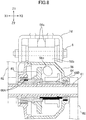
- the auxiliary housing 55 is in communication with the interior of the front housing 56 through the through hole 55d and a through hole 56d (see FIG. 8 ) formed on the front housing 56.
- the electric wire connected to the pedal force sensor 64 is connected to the vehicle controller 11 inside the auxiliary housing 55 though the through holes 55d and 56d.
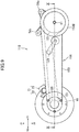
- the rear arm 150 includes an arm rear part 151 including the supporting shaft B, a front housing 156 accommodating the pedal force sensor 64, and an auxiliary housing 155 accommodating the motor driver 12 and the vehicle controller 11.
- the rear arm 150 includes a chain accommodation part D accommodating the transmission chain 127.
- the front part of the chain accommodation part D, the front housing 156, and the auxiliary housing 155 are formed by three members that are coupled together in the left-right direction. That is, the front part of the rear arm 150 includes a left cover 150A, a right cover 150B, and a partition plate 150C.
- the front housing 156 and the auxiliary housing 155 are defined by the left cover 150A and the partition plate 150C.
- the motor driver 12 and the vehicle controller 11 are fixed to the left cover 150B.
- the front part of the chain accommodation part D is defined by the right cover 150B and the partition plate 150C.
- the rear arm 150 includes a tube-like chain case 153 for connecting the housing 151A of the arm rear part 151 to the front part of the rear arm 150 and forming the chain accommodation part D.
- the drive unit 110 may use a belt drive mechanism as the power transmission mechanism. That is, the drive unit 110 may include a pulley fixed to the crank shaft 61, a pulley fixed to the transmission shaft 21, and a belt engaged by these two pulleys.
- the bicycle may have only the assisted mode and the human-powered mode, and not have the electric mode in which the bicycle runs only by power of the electric motor 30. In this case, the bicycle may not have the accelerator grip 4a and the accelerator sensor 4b.
Landscapes
- Engineering & Computer Science (AREA)
- Chemical & Material Sciences (AREA)
- Combustion & Propulsion (AREA)
- Transportation (AREA)
- Mechanical Engineering (AREA)
- Electric Propulsion And Braking For Vehicles (AREA)
- Connection Of Motors, Electrical Generators, Mechanical Devices, And The Like (AREA)
- Axle Suspensions And Sidecars For Cycles (AREA)
Abstract
Description
- The present invention relates to a bicycle with an electric motor and a drive unit of the bicycle.
-
JP2014-240267A - In the bicycle of
JP2014-240267A - One of the objects of the present disclosure is to improve workability of maintenance operation of a bicycle and a drive unit capable of being driven by human power and an electric motor.
- (1) A drive unit proposed in this disclosure includes a rear hub provided to a rear wheel; a rear arm; a first power system including an electric motor, the electric motor being accommodated in the rear wheel and including a rotor and a stator, the first power system being configured to transmit rotation of the rotor to the rear hub; and a second power system including a crank shaft having pedals attached thereto, and configured to transmit rotation of the crank shaft to the rear hub. The second power system includes a transmission shaft and a power transmission mechanism, the transmission shaft being rotatable and disposed radially inward of the stator, the power transmission mechanism coupling the crank shaft to the transmission shaft, the second power system being configured to transmit the rotation of the crank shaft to the rear hub through the power transmission mechanism and the transmission shaft. The rear arm and the power transmission mechanism are disposed in a first direction, which is one of a rightward direction and a leftward direction, with respect to a center of the rear wheel in a left-right direction. The transmission shaft is coupled to the rear hub at a position in a second direction, which is a direction opposite to the first direction, with respect to the center of the rear wheel in the left-right direction. According to the drive unit, a maintenance operator can easily access the electric motor, for example, and this improves the workability of the maintenance operation.
- (2) The drive unit according to (1) may further include a supporting shaft formed like a tube extending from a rear part of the rear arm in the second direction. The transmission shaft may be disposed radially inward of the supporting shaft. The stator may be fixed to radially outward of the supporting shaft. In this manner, the stator can be supported with a simple structure.
- (3) In the drive unit according to (2), the rear hub may include a first wall located in the first direction and a second wall located in the second direction. The transmission shaft and the supporting shaft may extend in the second direction through an opening formed on the first wall and to be coupled to the second wall.
- (4) In the drive unit according to (2), the rear hub may be rotatably supported by the supporting shaft. In this manner, the rear hub can be supported with a simple structure.
- (5) In the drive unit according to (4), first bearings may be fitted to radially outward of the supporting shaft, and the rear hub may be rotatably supported by the supporting shaft through the first bearings.
- (6) In the drive unit according to (5), the first bearing may be disposed in the first direction with respect to the center of the rear wheel in the left-right direction, the second bearing may be disposed in the second direction with respect to the center of the rear wheel in the left-right direction, and the rear hub may be rotatably supported by the supporting shaft through the second bearing.
- (7) In the drive unit according to any one of (1) to (6), a one-way clutch may be disposed in the power transmission path from the crank shaft to the rear hub, the one-way clutch allowing transmission of rotational force from the crank shaft to the rear hub and prevents transmission of rotational force from the rear hub to the crank shaft, In this manner, when the bicycle is running only by power of the electric motor, the crank shaft can be prevented from rotating. As a result, it is possible to reduce loss of power of the electric motor.
- (8) In the drive unit according to (7), the one-way clutch may be disposed downstream of the power transmission mechanism. This can prevent the power transmission mechanism from moving when the bicycle is running only by power of the electric motor. As a result, it is possible to further reduce loss of power of the electric motor.
- (9) In the drive unit according to (7), the one-way clutch may be disposed between the transmission shaft and the rear hub. This can prevent the transmission shaft from rotating when the bicycle is running only by power of the electric motor. As a result, it is possible to further reduce loss of power of the electric motor.
- (10) In the drive unit according to (5), an electric wire connected to the stator may be routed radially inward of the first bearing. This allows the electric wire to extend toward the rear arm, which serves to simplify a layout of the electric wire.
- (11) In the drive unit according to any one of (2) to (6), a path through which the electric wire connected to the stator is routed may be formed on the supporting shaft. This allows the electric wire to extend toward the rear arm, which serves to simplify a layout of the electric wire.
The transmission shaft may include a part that further projects than the supporting shaft in the first direction, and the power transmission mechanism may be coupled to the part of the transmission shaft. - (12) In the drive unit according to any one of (1) to (11), the transmission shaft may be rotatably supported at opposite ends. This structure can effectively prevent the transmission shaft from being deformed compared to a structure where the bearings are disposed in the supporting shaft and the transmission shaft is supported by the bearings.
- (13) In the drive unit according to any one of (1) to (12), the transmission shaft may be a first transmission shaft, and the power transmission mechanism may include a second transmission shaft that transmits power from the crank shaft to the first transmission shaft. Alternatively, the power transmission mechanism may include a transmission chain that transmits power from the crank shaft to the transmission shaft. The power transmission mechanism may be accommodated in the rear arm.
- (14) The drive unit according to any one of (1) to (13) may further include a motor driver that supplies electric current to the electric motor, and the motor driver may be supported by the rear arm. This can shorten a length of an electric wire that supplies power to the electric motor,
- (15) A bicycle proposed in this disclosure includes the drive unit according to any one of (1) to (14).
-
-
FIG. 1 is a side view of an example of a bicycle proposed in this disclosure; -
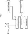
FIG. 2 is a block diagram showing a configuration of the exampled bicycle; -
FIG. 3 is a perspective view of a drive unit of the exampled bicycle; -
FIG. 4 is a perspective view of the drive unit of the exampled bicycle. InFIG. 4 , an electric motor is detached from the drive unit, and the auxiliary housing is disassembled; -
FIG. 5 is a cross sectional view of the drive unit taken along the line V-V inFIG. 1 ; -
FIG. 6 is an enlarged view ofFIG. 5 ; -
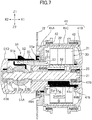
FIG. 7 is a cross sectional view of the drive unit taken along the line VII-VII inFIG. 1 ; -
FIG. 8 is a cross sectional view of the drive unit taken along the line VIII-VIII inFIG. 1 ; -
FIG. 9 is a side view of the drive unit including a chain as a power transmission mechanism; and -
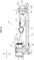
FIG. 10 is a cross sectional view of the drive unit taken along the line X-X inFIG. 9 . - Examples of a bicycle and a drive unit proposed in this disclosure will be described. The terminology used herein is for the purpose of describing particular embodiments only and is not intended to be limiting of the invention. As used herein, the term "and/or" includes any and all combinations of one or more of the associated listed items. As used herein, the singular forms "a," "an," and "the" are intended to include the plural forms as well as the singular forms, unless the context clearly indicates otherwise. It will be further understood that the terms "comprises", "comprising", "includes", and/or "including", when used in this specification, specify the presence of stated features, steps, operations, elements, and/or components, but do not preclude the presence or addition of one or more other features, steps, operations, elements, components, and/or groups thereof.
- Unless otherwise defined, all terms (including technical and scientific terms) used herein have the same meaning as commonly understood by one having ordinary skill in the art to which this invention belongs. It will be further understood that terms, such as those defined in commonly used dictionaries, should be interpreted as having a meaning that is consistent with their meaning in the context of the relevant art and the present disclosure and will not be interpreted in an idealized or overly formal sense unless expressly so defined herein.
- In describing the invention, it will be understood that a number of technologies are disclosed. Each of these has individual benefit and each can also be used in conjunction with one or more, or in some cases all, of the other disclosed technologies. Accordingly, for the sake of clarity, this description will refrain from repeating every possible combination of the individual technologies in an unnecessary fashion. Nevertheless, the specification and claims should be read with the understanding that such combinations are entirely within the scope of the invention and the claims.
- In the following description, for purposes of explanation, numerous specific details are set forth in order to provide a thorough understanding of the present invention. It will be evident, however, to one skilled in the art that the present invention may be practiced without these specific details.
- The present disclosure is to be considered as an exemplification of the invention, and is not intended to limit the invention to the specific embodiments illustrated by the figures or description below. As an example, a bicycle 1 and a
drive unit 10 shown in the drawings such asFIG. 1 will be described herein. InFIG. 1 , arrows Y1 and Y2 respectively indicate forward and rearward directions, and arrows Z1 and Z2 respectively indicate upward and downward directions. InFIG. 5 , arrows X1 and X2 respectively indicate rightward and leftward directions, and a direction indicated by arrows X1-X2 is referred to as a left-right direction or an axial direction. - As shown in
FIG. 1 , the bicycle 1 includes a front fork 3, afront wheel 2 held at the lower edge of the front fork 3, and ahandle bar 4 connected to the front fork 3 through the steering shaft. The bicycle 1 includes aseat 6 at a position rearwardly apart from thehandle bar 4. Theseat 6 is fixed at the upper edge of aseat post 7a. - A crank 60 is disposed below the
seat post 7a. The crank 60 includes a crank shaft 61 (seeFIG. 5 ), crankarms 62 attached to the opposite ends of thecrank shaft 61, andpedals 63 attached to the crankarms 62. - The
vehicle frame 7 includes theseat post 7a, ahead pipe 7b supporting the steering shaft, and a down frame 7c obliquely extending from thehead pipe 7b downward. The lower end of theseat post 7a and the lower end of the down frame 7c are fixed to abracket 7d. The drive unit 10 (seeFIG. 3 ) of the bicycle 1 includes afront housing 56, which is located at the forefront part of arear arm 50 described later and holds the crank 60. Thefront housing 56 is coupled to thebracket 7d. The bicycle 1 includes abattery 13 for storing power to be supplied to anelectric motor 30 described later. Thebattery 13 is attached to, for example, the down frame 7c. The structure of thevehicle frame 7, the supporting structure of thefront housing 56, and the location of thebattery 13 are not limited to the above described examples. - As shown in
FIG. 2 , anaccelerator grip 4a is provided at the right part of thehandle bar 4. Theaccelerator grip 4a includes anaccelerator sensor 4b for detecting an amount of operation (rotational position) of theaccelerator grip 4a. The bicycle 1 includes arear wheel 40 and an electric motor 30 (seeFIG. 5 ) attached to therear wheel 40. An output signal of theaccelerator sensor 4b is fed into avehicle controller 11. Thevehicle controller 11 generates an instruction value according to an operation amount of theaccelerator grip 4a. Themotor driver 12 supplies theelectric motor 30 with power according to the instruction value. Themotor driver 12 includes an inverter that converts DC power from thebattery 13 into AC power of a frequency according to the instruction value, for example, and then supplies the converted power to theelectric motor 30. At this time, the bicycle 1 can be driven only by the power from theelectric motor 30. - The rotational force of the crank shaft 61 (see
FIG. 5 ) is transmitted to therear wheel 40 through a power transmission mechanism described later. Thecrank shaft 61 includes a sensor 64 (seeFIG. 5 ) that detects force (pedal force) applied by a user to the pedals 63 (hereinafter,sensor 64 is referred to as "pedal force sensor"). Thepedal force sensor 64 is a sensor (e.g., magnetorestrictive sensor) that outputs, for example, a signal according to torsion of thecrank shaft 61. As shown inFIG. 2 , an output signal of thepedal force sensor 64 is fed into thevehicle controller 11. Thevehicle controller 11 generates an instruction value according to the pedal force. Themotor driver 12 supplies theelectric motor 30 with power according to the instruction value, and theelectric motor 30 is driven with the supplied power. With theelectric motor 30 being driven in this way, a user's pedaling of thepedals 63 is assisted. When theelectric motor 30 is not operating, therear wheel 40 drives only by the rotational force from thecrank shaft 61 through the power transmission mechanism. - Briefly, the bicycle 1 can be driven in the following three modes: (i) Electric mode (driven only by power of the electric motor 30); (ii) Assisted mode (driven by the
electric motor 30 and pedal force applied to thepedals 63; and (iii) Human-powered mode (driven only by pedal force applied to the pedals 63). The bicycle 1 may have a switch for a user to switch these three modes. - The structure and the operations proposed in this disclosure are not limited to be applied to the bicycle that can select these three modes, but may also be applied to a bicycle that can select only (ii) assisted mode and (iii) human-powered mode, for example. In this case, the bicycle may not include the
accelerator grip 4a and theaccelerator sensor 4b. - In the following, the structure of the
drive unit 10 will be described. Thedrive unit 10 includes two power systems. A first power system includes theelectric motor 30, and transmits rotation of arotor 32 included in theelectric motor 30 to ahub 41 of therear wheel 40. A second power system includes thecrank shaft 61 to which thepedals 63 are attached, and transmits rotation of thecrank shaft 61 to thehub 41 of therear wheel 40. - As shown in
FIG. 5 , theelectric motor 30 includes astator 31 and arotor 32. Thestator 31 includes a plurality of iron cores, which are arranged in a circular manner around the rotation center Ax1 of therear wheel 40, and coils wound around the iron cores. Therotor 32 includes a plurality of magnets arranged in a circular manner around the rotation center Ax1 of therear wheel 40, and is rotatable around the rotation center Ax1. Therotor 32 of the bicycle 1 is located radially outward of thestator 31, and radially opposed to thestator 31. That is, theelectric motor 30 is a radial gap electric motor. Unlike the example of the bicycle 1, theelectric motor 30 may be an axial gap electric motor. In other words, therotor 32 and thestator 31 may be opposed to each other in the axial direction (the direction of the rotation center Ax1). - As shown in
FIG. 5 , therear wheel 40 includes arim 43 to which atire 44 is attached, and thehub 41. Therear wheel 40 also includes aspoke 45 radially extending from thehub 41 and supporting therim 43. The rotor (magnet) 32 is fixed to the inner surface of therear hub 41, and therotor 32 rotates integrally with therear hub 41. There is no speed reducer (for example, gears) between therear hub 41 and theelectric motor 30, and thus therear wheel 40 can be effectively driven without power losses due to the speed reducer. - As described above, the front part of the
drive unit 10 includes thecrank shaft 61 to which thepedals 63 are attached. As shown inFIG. 5 , a gear 65 (bevel gear in the exampled bicycle 1), which integrally rotates with thecrank shaft 61, and thepedal force sensor 64 described above are disposed on thecrank shaft 61. A power transmission path (second power system) through which power (rotation) of thecrank shaft 61 is transmitted to therear hub 41 includes atransmission shaft 21 disposed apart from thecrank shaft 61 rearward. Thetransmission shaft 21 is located at the rotation center Ax1 of therear wheel 40. As described later, the rear part of therear arm 50 includes an armrear part 51, and thetransmission shaft 21 is rotatably supported by the armrear part 51. - The second power system includes the power transmission mechanism for transmitting the power (rotational force) of the
crank shaft 61 to thetransmission shaft 21. In theexampled drive unit 10, the power transmission mechanism is a shaft drive mechanism. That is, as shown inFIG. 5 , the power transmission mechanism includes thegear 65 provided on thecrank shaft 61, a gear 26 (specifically, bevel gear) provided on thetransmission shaft 21, and atransmission shaft 27 arranged in the front-rear direction of the vehicle body when viewed from the side of the vehicle (in the following, thetransmission shaft 21 is referred to as "first transmission shaft", and thetransmission shaft 27 is referred to as "second transmission shaft"). The front end of thesecond transmission shaft 27 includes agear 27A (specifically, bevel gear) that is engaged with thegear 65 on thecrank shaft 61. The rear end of thesecond transmission shaft 27 includes agear 27B (specifically, bevel gear) that is engaged with thegear 26 on thefirst transmission shaft 21. Thedrive unit 10 may include a chain drive mechanism and a belt drive mechanism as the power transmission mechanism. In other words, the bicycle 1 may include a chain and a belt instead of thesecond transmission shaft 27. - The
first transmission shaft 21 is coupled to therear hub 41. In detail, thefirst transmission shaft 21 is coupled to therear hub 41 through a one-way clutch 23 (seeFIG. 6 ). The one-way clutch 23 transmits the rotational force of thefirst transmission shaft 21 to therear hub 41, but does not transmit the rotational force of therear hub 41 to thefirst transmission shaft 21. The supporting structure of thefirst transmission shaft 21 and the location of the one-way clutch 23 will be described later in detail. - The
rear arm 50 is disposed either rightward or leftward of therear wheel 40 and theelectric motor 30, and not disposed on the other. In theexampled drive unit 10, as shown inFIG. 5 , there is arear arm 50 on the left side of therear wheel 40, and there is no rear arm on the right side. As such, a maintenance operator can easily access therear wheel 40 and theelectric motor 30, and this improves the workability of the maintenance operation. For example, the operator can easily detach aright wall 41B of therear hub 41. In contrast to the exampled bicycle 1, therear arm 50 may be disposed only rightward of therear wheel 40. - The power transmission mechanism that transmits the rotation of the
crank shaft 61 to thefirst transmission shaft 21 is disposed together with therear arm 50 leftward of therear wheel 40 and theelectric motor 30. In other words, thesecond transmission shaft 27 is disposed on the same side as therear arm 50 with respect to the center C1 of therear wheel 40 in the left-right direction. Accordingly, the power transmission mechanism is coupled to the left part of thefirst transmission shaft 21. Thestator 31 is supported by the rear part 51 (hereinafter referred to as arm rear part) of therear arm 50. The armrear part 51 is located leftward of thestator 31. Thefirst transmission shaft 21 extends rightward from the armrear part 51 side, and is disposed radially inward of thestator 31. Thefirst transmission shaft 21 is coupled to therear hub 41, on the opposite side (i.e., on the right) to the power transmission mechanism and therear arm 50 across the center C1 of theelectric motor 30 in the left-right direction. In other words, thefirst transmission shaft 21 is coupled to theright wall 41B (seeFIG. 6 ) of therear hub 41. This structure allows therear arm 50 located only leftward to support theelectric motor 30 and the power transmission from thecrank shaft 61 to therear hub 41. - As shown in
FIG. 5 , the front part of therear arm 50 includes thefront housing 56 holding the crank 60. Therear arm 50 includes theshaft case 53 formed like a tube and extending from thefront housing 56 rearward. Thesecond transmission shaft 27 is accommodated in theshaft case 53, and rotatably held by a bearing provided to theshaft case 53. Thegear 27A at the front end of thesecond transmission shaft 27 is located inside thefront housing 56. Thegear 27B at the rear end of thesecond transmission shaft 27 is accommodated in ahousing 51A of the armrear part 51 described later. - As shown in
FIG. 5 , thehousing 51A is located leftward away from the center C1 of therear wheel 40 in the left-right direction (that is, the center of the vehicle in the left-right direction). Theshaft case 53 extends obliquely frontward from thehousing 51A toward the center C1. The front end of theshaft case 53 is located in front of therear wheel 40 or theelectric motor 30. - As described above, the bicycle 1 may employ a chain drive mechanism or a belt drive mechanism as the power transmission mechanism. In this case, the
rear arm 50 may include a case instead of theshaft case 53 so as to accommodate the chain or the belt. In still another example, the bicycle 1 may not include a case for accommodating the power transmission mechanism. - The arm
rear part 51 of therear arm 50 is connected to the rear end of the shaft case 53 (seeFIG. 5 ). As shown inFIG. 6 , the armrear part 51 includes thehousing 51A described above. Thehousing 51A is connected to the rear end of theshaft case 53. In theexampled drive unit 10, the armrear part 51 includes afront cover 51E that has an opening, to which the rear end of theshaft case 53 is fitted, and is fixed to the rear end of theshaft case 53. Thehousing 51A is fixed to thefront cover 51E by a fixture such as a screw, thereby forming an accommodation part for accommodating thegears housing 51A can protect the power transmission mechanism (specifically, gears 27B and 26). The structure for connecting the armrear part 51 to theshaft case 53 is not limited to the example of the bicycle 1, and may be varied as appropriate. - As shown in
FIG. 6 , thedrive unit 10 includes a supporting shaft B that supports theelectric motor 30 and therear wheel 40. The supporting shaft B extends rightward from the armrear part 51. The supporting shaft B is a tube-like member arranged along the rotation center Ax1 of therear wheel 40 and theelectric motor 30, and is not rotatable. Thefirst transmission shaft 21, which transmits the rotational force of thecrank shaft 61 to therear hub 41, is disposed inside the supporting shaft B. The supporting shaft B supports therear hub 41 through thebearings rear wheel 40. The layout of thebearings - In the
exampled drive unit 10, the supporting shaft B is composed of two members fixed to each other. Specifically, as shown inFIG. 6 , the supporting shaft B includes ashaft body 51B and aconnected shaft 51C. Each of theshaft body 51B and theconnected shaft 51C is a tube-like members, and those are fixed to each other in the axial direction. In other words, the supporting shaft B can be divided in the axial direction. Thestator 31 of theelectric motor 30 is fixed to the outer peripheral surface of theconnected shaft 51C. For example, the iron cores constituting thestator 31 are welded or bonded to the outer peripheral surface of theconnected shaft 51C. As such, theconnected shaft 51C is employed as a holder for thestator 31. Theshaft body 51B is integrally formed with thehousing 51A. Theconnected shaft 51C is located rightward of theshaft body 51B, and fixed to theshaft body 51B by a fixture, such as a screw 59 (seeFIG. 7 ) and a bolt. In the exampled bicycle 1, thescrew 59 is located radially inward of thestator 31. The supporting shaft B is constituted by two members (that is, theshaft body 51B and theconnected shaft 51C) in this way, and this enhances ease of assembly of thedrive unit 10. For example, in the assembly process of thedrive unit 10, it is possible to fix thestator 31 to the outer peripheral surface of theconnected shaft 51C, and then connect theconnected shaft 51C to theshaft body 51B using thescrew 59. - The configuration of the supporting shaft B is not limited to the example of the
drive unit 10. Theshaft body 51B and theconnected shaft 51C of the supporting shaft B may be integrally formed. In this case, a stator may be fitted outside of the supporting shaft B, and the inner periphery of the stator may be fixed to the outer peripheral surface of the supporting shaft B. In still another example, theshaft body 51B and thehousing 51A may be separately formed. Theshaft body 51B and thehousing 51A may be fixed to each other by a fixture, such as a screw. - As shown in
FIG. 6 , therear hub 41 includes aright wall 41B and aleft wall 41A. Theright wall 41B is located rightward of the center C1 (center of the electric motor 30) of therear wheel 40 in the left-right direction, and covers the right side of theelectric motor 30. Theleft wall 41A is located leftward of the center C1 of therear wheel 40, and covers the left side of theelectric motor 30. In the exampled bicycle 1, therear hub 41 includes amiddle wall 41C formed into a cylindrical shape and located between theright wall 41B and theleft wall 41A. Themiddle wall 41C covers the outer peripheral surface of theelectric motor 30. The rotor (magnet) 32 described above is fixed to the inner surface of themiddle wall 41C. As shown inFIG. 7 , the outer circumference of theright wall 41B is fixed to themiddle wall 41C by a fixture, such as ascrew 42 or a bolt. Similarly, the outer circumference of theleft wall 41A is fixed to themiddle wall 41C by a fixture, such as ascrew 42 or a bolt. - The configuration of the
rear hub 41 is not limited to the example of the bicycle 1. Therear hub 41 may be formed of two members. For example, theleft wall 41A (or theright wall 41B) and themiddle wall 41C may be integrally formed. - As shown in
FIG. 6 , anopening 41a that opens in the axial direction is formed on theleft wall 41A. The supporting shaft B and thefirst transmission shaft 21 are disposed inside of theopening 41a. That is, the supporting shaft B and thefirst transmission shaft 21 extend through theopening 41a from the inside of therear hub 41 to the outside of therear hub 41. In the exampled bicycle 1, therear arm 50 is disposed only leftward of therear wheel 40. As such, unlike theleft wall 41A, theright wall 41B of therear hub 41 does not have an opening through which the supporting shaft B and thefirst transmission shaft 21 are routed. - The
rear hub 41 is supported through aleft bearing 49A and aright bearing 49B, which are spaced apart from each other in the left-right direction. The twobearings rear wheel 40. As shown inFIG. 6 , the left bearing 49A is disposed between the inner peripheral surface of theopening 41a of theleft wall 41A and the outer peripheral surface of the supporting shaft B (more specifically,shaft body 51B). Theright bearing 49B is disposed between theright wall 41B of therear hub 41 and the outer peripheral surface of the supporting shaft B (more specifically,connected shaft 51C). Specifically, a supportedportion 41b projecting in the axial direction (leftward in the exampled drive unit 10) is formed on the inner surface of theright wall 41B. The supportedportion 41b is annular when viewed in the axial direction. Theright bearing 49B is disposed between the inner peripheral surface of the supportedportion 41b and the outer peripheral surface of theconnected shaft 51C. - As described above, the supporting shaft B supports the
rear hub 41 through thebearings rear hub 41. The structure for supporting therear hub 41 is not limited to the example of thedrive unit 10. For example, in contrast to the example of thedrive unit 10, the supportedportion 41b of theright wall 41B may be located inside of the end part of the tube-like supporting shaft B. In this case, theright bearing 49B may be disposed between the outer peripheral surface of the supportedportion 41b of theright wall 41B and the inner peripheral surface of the supporting shaft B. - Between the two
bearings rear arm 50 is wider than the other. In the exampled bicycle 1, the width of the left bearing 49A in the axial direction is wider than the width of theright bearing 49B. This increases durability of the supporting structure of therear hub 41. - As shown in
FIG. 6 , aseal 48 is disposed between the inner peripheral surface of theopening 41a of the left wall 41Ab and the outer peripheral surface of the supporting shaft B (more specifically,shaft body 51B). Theseal 48 is located outwardly from the bearing 49A in the axial direction (in theexampled drive unit 10, leftward). - As shown in
FIGs. 6 and7 , theshaft body 51B includes a large-diameter part 51f and a small-diameter part 51g, which has a smaller diameter than the large-diameter part 51f. The large-diameter part 51f is located radially inward of theleft bearing 49A. In the exampled bicycle 1, a cable passage (through hole) 51a is formed on the large-diameter part 51f, and anelectric cable 33 described later is routed through thecable passage 51a (seeFIGs. 4 and7 ). The small-diameter part 51g is located rightward of the large-diameter part 51f, and fixed to theconnected shaft 51C. Theconnected shaft 51C, to which thestator 31 is fixed, has substantially the same diameter as the small-diameter part 51g. Astopper plate 57 is attached to the side surface of the large-diameter part 51f so as to prevent the left bearing 49A from falling out. Further, aguide plate 58 is attached to the side surface of the large-diameter part 51f so as to guide a position of an electric wire connected to thestator 31. - As shown in
FIG. 6 , a radially extendingflange part 51c is formed at the end of the supporting shaft B (specifically,connected shaft 51C). Theflange part 51c prevents theright bearing 49B from moving outward in the axial direction (rightward in the example of the drive unit 10). In the assembly process of thedrive unit 10, for example, theright bearing 49B is fitted outside of theconnected shaft 51C, and then thestator 31 is fixed to the outer peripheral surface of theconnected shaft 51C. Subsequently, theconnected shaft 51C is fixed to theshaft body 51B by a fixture, such as thescrew 59. The structure for preventing the right bearing 49B from falling out is not limited to the example of thedrive unit 10. - The bicycle 1 includes a
brake device 71 for therear wheel 40. As shown inFIG. 3 , thebrake device 71 is, for example, a disc brake device, and thus includes abrake disc 72, which integrally rotates with therear hub 41, andcalipers 73. As shown inFIG. 6 , thebrake disc 72 is attached to, for example, theleft wall 41A. As such, the supporting shaft B and thefirst transmission shaft 21 are located radially inward of thebrake disc 72. Thecalipers 73 are supported by therear arm 50. For example, thecalipers 73 are supported by theshaft case 53 through the bracket 53a (seeFIG. 3 ). The configuration of thebrake device 71 is not limited to the example of thedrive unit 10. For example, thebrake device 71 may be a drum brake device. In this case, a brake drum may be attached to theleft wall 41A. - As shown in
FIG. 6 , the supporting shaft B and thefirst transmission shaft 21 project leftward from theopening 41a of therear hub 41. Thefirst transmission shaft 21 extends further leftward than the supporting shaft B, and thus includes apart 21a (hereinafter referred to as connection part) that is located further leftward than the supporting shaft B. Theconnection part 21a is connected to thesecond transmission shaft 27. In theexampled drive unit 10, theconnection part 21a is connected to thesecond transmission shaft 27 through thegears gear 26 on theconnection part 21a is located further outward (more specifically, leftward) than thegear 27B of thesecond transmission shaft 27 in the axial direction. - As described above, the
first transmission shaft 21 is connected to therear hub 41, on the opposite side to therear arm 50 and the power transmission mechanism (in the exampled bicycle 1,second transmission shaft 27 and gears 26 and 27B) across the center C1 of therear wheel 40 so that power can be transmitted from thefirst transmission shaft 21 to therear hub 41. In other words, thefirst transmission shaft 21 is connected to a wall part opposite to a wall part where theopening 41a is formed (in the example of thedrive unit 10,right wall 41B). - In the
exampled drive unit 10, thefirst transmission shaft 21 is connected to theright wall 41B through the one-way clutch 23 which allows power to be transmitted to therear hub 41 and prevents power transmission in the opposite direction. As shown inFIG. 6 , aconnection part 41c is formed on the inner surface of theright wall 41B. Theconnection part 41c projects from the inner surface of theright wall 41B in the axial direction, and is annular when viewed in the axial direction. Theconnection part 41c is located radially inward of the end of the supporting shaft B (specifically,connected shaft 51C). The end (right end) of thefirst transmission shaft 21 is located radially inward of theconnection part 41c. The one-way clutch 23 is disposed between the inner peripheral surface of theconnection part 41c and the outer peripheral surface of thetransmission shaft 21. - In this manner, the one-way clutch 23 is located downstream of the
second transmission shaft 27 in the power transmission path extending from thecrank shaft 61 to therear hub 41. As such, for example, when the bicycle 1 is running only by the power of theelectric motor 30, rotation of thesecond transmission shaft 27 is not generated. As a result, it is possible to prevent the power of theelectric motor 30 from being wasted by the rotation of thesecond transmission shaft 27. Specifically, in the exampled bicycle 1, the one-way clutch 23 is located downstream of thefirst transmission shaft 21 in the power transmission path. As such, when the bicycle 1 is running only by the power of theelectric motor 30, not only the rotation ofsecond transmission shaft 27 but also the rotation of thefirst transmission shaft 21 is not generated. - The location of the one-way clutch 23 is not limited to the example of the
drive unit 10. For example, thefirst transmission shaft 21 may be formed of two members that are connected to each other in the axial direction, and the one-way clutch 23 may be disposed between the two members. In still another example, the one-way clutch 23 may be disposed between thefirst transmission shaft 21 and thegear 26 on thefirst transmission shaft 21, or between thesecond transmission shaft 27 and thegear 27B on thesecond transmission shaft 27. - As described, the supporting shaft B is not rotatable, while the
first transmission shaft 21 disposed inside of the supporting shaft B is rotatable. As shown inFIG. 6 , thefirst transmission shaft 21 is rotatably supported through thebearings exampled drive unit 10, thebearings first transmission shaft 21. That is, thefirst transmission shaft 21 is rotatably supported at the opposite ends thereof. Such placement of thebearings first transmission shaft 21. For example, deformation of thefirst transmission shaft 21 can be effectively prevented compared to the structure of disposing thebearings first transmission shaft 21 and supporting thefirst transmission shaft 21 by the supporting shaft B. - As shown in
FIG. 6 , in theexampled drive unit 10, similarly to the one-way clutch 23, theright bearing 47B is disposed between the inner peripheral surface of theconnection part 41c of therear hub 41 and the outer peripheral surface of thefirst transmission shaft 21. As such, clearance between the inner peripheral surface of theconnection part 41c and the outer peripheral surface of the first transmission shaft 21 (clearance in which the one-way clutch 23 is disposed) can be maintained by the bearing 47B with high accuracy. In theexampled drive unit 10, the bearing 47B is located further outward (specifically, rightward) than the one-way clutch 23 in the axial direction. - As shown in
FIG. 6 , the armrear part 51 of therear arm 50 is located outward of thefirst transmission shaft 21 in the axial direction (leftward in the exampled drive unit 10), and includes aleft cover 51D for covering thehousing 51A. The left bearing 47A is held inside of theleft cover 51D. Specifically, a recess is formed on the inner surface of theleft cover 51D, and the bearing 47A is fitted into the recess. As such, the bearing 47A is located further outward than thegear 26 of thefirst transmission shaft 21 in the axial direction (specifically, leftward). This prevents thefirst transmission shaft 21 from being deformed, and enables to highly accurately maintain the relative positions of thegear 26 on thefirst transmission shaft 21 and thegear 27B on thetransmission shaft 27. - As described, the left end of the
first transmission shaft 21 is supported by the armrear part 51 through thebearing 47A. The right end of thefirst transmission shaft 21 is supported by theright wall 41B of therear hub 41 through the bearing 47B. As described above, theright wall 41B of therear hub 41 is supported by the supporting shaft B of therear arm 50, and thus the right end of thefirst transmission shaft 21 is indirectly supported by the supporting shaft B. - The supporting structure of the
first transmission shaft 21 is not limited to the example of thedrive unit 10. For example, one or both of thebearings first transmission shaft 21. That is, one or both of thebearings first transmission shaft 21. - As shown in
FIG. 6 , a clearance is provided between the inner peripheral surface of the supporting shaft B and the outer peripheral surface of thefirst transmission shaft 21. As such, friction is not generated between thefirst transmission shaft 21 and the supporting shaft B, and thus thefirst transmission shaft 21 can rotate smoothly. As described above, thefirst transmission shaft 21 includes theconnection part 21a that is located further leftward than the supporting shaft B. Thisconnection part 21a is located inside of an accommodation part defined by thehousing 51A and theleft cover 51D. This structure can prevent external dusts and moisture from entering the interior of therear hub 41 through the clearance between the inner peripheral surface of the supporting shaft B and the outer peripheral surface of thefirst transmission shaft 21. - As shown in
FIG. 7 , thedrive unit 10 includes theelectric cable 33. Theelectric cable 33 includes an electric wire connected to thestator 31, and an electric wire connected to an encoder that detects rotational speed of theelectric motor 30. Theannular guide plate 58 is disposed inside of therear hub 41 so as to guide the position of theelectric cable 33. Theelectric cable 33 is located between theguide plate 58 and the small-diameter part 51g of the supporting shaft B (shaft body 51B). Theelectric cable 33 is routed radially inward of the left bearing 49A, and extends from inside to outside of therear hub 41. This configuration allows theelectric cable 33 to extend toward therear arm 50. Theelectric cable 33 is arranged along therear arm 50, and the ends of the electric wire included in theelectric cable 33 are connected to themotor driver 12 and/or the vehicle controller 11 (seeFIG. 2 ). - As shown in
FIG. 7 , thecable passage 51a, through which theelectric cable 33 is routed, is formed on the supporting shaft B. Thecable passage 51a allows communication between the interior of therear hub 41 and the interior of thehousing 51A. That is, thecable passage 51a is not in communication with the exterior of the vehicle, but in communication with the interior of thehousing 51A. This prevents external dusts and moisture from entering the interior of therear hub 41 through thecable passage 51a. - As shown in
FIG. 7 , the supporting shaft B includes a hole penetrating the supporting shaft B in the axial direction. This through hole functions as thecable passage 51a. As described above, the supporting shaft B includes theshaft body 51B and theconnected shaft 51C that are connected to each other in the axial direction. The large-diameter part 51f of theshaft body 51B has a diameter larger than the small-diameter part 51g and theconnected shaft 51C, and the right side surface of theshaft body 51B is exposed inside therear hub 41. Thecable passage 51a is formed on the right side surface of theshaft body 51B. Thecable passage 51a is disposed above thefirst transmission shaft 21, for example. - The configuration of the
cable passage 51a is not limited to the example of thedrive unit 10. For example, a groove may be formed on the outer peripheral surface of the supporting shaft B (specifically, on the outer peripheral surface of large-diameter part 51f ofshaft body 51B). Such a groove may be used as thecable passage 51a. In this case as well, theelectric cable 33 is disposed radially inside theleft bearing 49A. In still another example, an annular member (collar) may be disposed radially between the outer peripheral surface of theshaft body 51B and theleft bearing 49A. A through hole may be formed on the annular member to function as thecable passage 51a. - In the
exampled drive unit 10, theelectric cable 33 is routed through thehousing 51A, and, as shown inFIG. 3 , extends forward along the rear arm 50 (more specifically, along the shaft case 53). The wall (front cover 51E, seeFIG. 3 ) on the front side of thehousing 51A has a throughhole 51e (seeFIG. 7 ) penetrating through the wall. Theelectric cable 33 is routed through the throughhole 51e, and extends forward from the interior of thehousing 51A. The throughhole 51e is located, for example, above thegear 27B of thesecond transmission shaft 27. - As shown in
FIG. 7 , acable guide 52 may be disposed inside thehousing 51A. Thecable guide 52 guides the position of theelectric cable 33 in the interior of thehousing 51A. Thecable guide 52 is disposed so as to prevent interference between thegears housing part 51A, and theelectric cable 33. Specifically, thecable guide 52 is disposed above and rightward of thegear 26, and above thegear 27B. - As described above, the
drive unit 10 includes the motor driver 12 (seeFIG. 2 ) having the inverter and supplying power stored in thebattery 13 to theelectric motor 30. In theexampled drive unit 10, themotor driver 12 is supported by therear arm 50. Specifically, as shown inFIGs. 4 and5 , therear arm 50 includes theauxiliary housing 55, and theauxiliary housing 55 accommodates themotor driver 12. This placement of themotor driver 12 can shorten the length of the power supplying electric wire extending from thebattery 13 to theelectric motor 30. In theexampled drive unit 10, theauxiliary housing 55 also accommodates thevehicle controller 11, which calculates an instruction value to themotor driver 12. - As shown in
FIG. 5 , in theexampled drive unit 10, theauxiliary housing 55 is located between thecrank shaft 61 and thefirst transmission shaft 21. Theauxiliary housing 55 is disposed in front of therear wheel 40, and at least a part of theauxiliary housing 55 overlaps with therear wheel 40 in the front view of the vehicle. Theauxiliary housing 55 is located behind thecrank shaft 61, and at least a part of theauxiliary housing 55 overlaps with thecrank shaft 61 in the front view of the vehicle. The placement of theauxiliary housing 55 can prevent an external object from colliding with theauxiliary housing 55. - As shown in
FIG. 4 , theauxiliary housing 55 includes aleft housing 55A and aright housing 55B that are combined with each other in the left-right direction. Theleft housing 55A has a box-like shape with the right side open, and theright housing 55B has a box-like shape with the left side open. Theleft housing 55A is attached to therear arm 50. In theexampled drive unit 10, theshaft case 53 penetrates theleft housing 55A in the front-rear direction. Thefront housing 56 is disposed in front of theleft housing 55A, and theleft housing 55A is fixed to thefront housing 56. Themotor driver 12 and thevehicle controller 11 are attached to the interior of theright housing 55B. Coolingfins 55a may be formed on the outer surface of theright housing 55B. - The position of the
auxiliary housing 55 and the structure of attaching theauxiliary housing 55 to therear arm 50 are not limited to the examples of thedrive unit 10. For example, theright housing 55B may be attached to theshaft case 53, and theleft housing 55A may be attached to theright housing 55B. In this case, themotor driver 12 and thevehicle controller 11 may be fixed to theleft housing 55A. In still another example, theauxiliary housing 55 may be formed of two members that are combined with each other in the front-rear direction. In still another example, theauxiliary housing 55 may be attached to the outer surface of theshaft case 53. In still another example, theelectric cable 33 may be routed through the interior of theshaft case 53. - As shown in
FIG. 4 , theauxiliary housing 55 has anopening 55b (hereinafter referred to as "cable opening") located aboveshaft case 53. Theelectric cable 33 enters into theauxiliary housing 55 through thecable opening 55b. In theexampled drive unit 10, thecable opening 55b is formed on theleft housing 55A, and theelectric cable 33 is located above theshaft case 53. This prevents interference between theelectric cable 33 and therear wheel 40 and between theelectric cable 33 and an obstacle on the path of the bicycle 1. Theelectric cable 33 enters from thecable opening 55b into theauxiliary housing 55, curves rightward, and extends to themotor driver 12 described above. Theauxiliary housing 55 includes aguide wall 55c therein to prevent interference between theelectric cable 33 and theshaft case 53. - As shown in
FIG. 4 , a throughhole 55d is formed on a wall in front of theauxiliary housing 55. Theauxiliary housing 55 is in communication with the interior of thefront housing 56 through the throughhole 55d and a throughhole 56d (seeFIG. 8 ) formed on thefront housing 56. The electric wire connected to thepedal force sensor 64 is connected to thevehicle controller 11 inside theauxiliary housing 55 though the throughholes - As shown in
FIG. 4 , the front part of therear arm 50 includes thefront housing 56 accommodating thegear 65 and thepedal force sensor 64, for example. Thefront housing 56 supports thecrank shaft 61 through thebearings crank shaft 61. The opposite ends of thecrank shaft 61 project from thefront housing 56 in the axial direction. Thepedals 63 are respectively fixed to the opposite ends of thecrank shaft 61. Thefront housing 56 accommodates thegear 65 and thepedal force sensor 64 that are disposed on the crank shaft 61 (seeFIG. 5 ). - The
front housing 56 is attached to thebracket 7d (seeFIG. 1 ) that is provided to the lowest part of thevehicle frame 7. Thebracket 7d is a box-like member with the bottom side open, for example. Thefront housing 56 is disposed inside thebracket 7d, and attached to thebracket 7d. As shown inFIG. 4 , thefront housing 56 includes afront connection part 56a and arear connection part 56b, which extend upward and are apart from each other in the front-rear direction. For example, a fixture 8 (specifically, bolt, seeFIG. 8 ) is inserted into theconnection parts bracket 7d in the left-right direction, and thus theconnection parts bracket 7d. - The
front housing 56 may be attached to thebracket 7d through a damper. In the exampled bicycle 1, adamper 56c is attached to therear connection part 56b ,and is vertically sandwiched by therear connection part 56b and thebracket 7d. Theconnection part 56b is attached to thebracket 7d so as to be slightly and vertically movable to thebracket 7d. As such, when the bicycle 1 swings, therear arm 50 is vertically movable around the fixture (specifically, bolt) inserted into thefront connection part 56a, and thedamper 56c dampens the vertical movement of therear arm 50. The structures of attaching thefront housing 56 to thevehicle frame 7 may not be limited to the example of thedrive unit 10, but may be varied as appropriate. -
- (1) As described above, the
drive unit 10 includes therear hub 41 provided on therear wheel 40, therear arm 50, the first power system, and the second power system. The first power system includes theelectric motor 30 that includes therotor 32, which is rotatable around the rotation center Ax1 of therear wheel 40, and thestator 31 and is accommodated in therear hub 41. The first power system transmits rotation of therotor 32 to therear hub 41. The second power system includes thecrank shaft 61 to which thepedals 63 are attached, and transmits rotation of thecrank shaft 61 to therear hub 41. The second power system includes thefirst transmission shaft 21 and the power transmission mechanism, and transmits rotation of thecrank shaft 61 to therear hub 41 through the power transmission mechanism and thefirst transmission shaft 21. Thefirst transmission shaft 21 is rotatable and disposed radially inward of thestator 31, and the power transmission mechanism couples thecrank shaft 61 to thefirst transmission shaft 21. Therear arm 50 and the power transmission mechanism are disposed leftward of the center C1 of therear wheel 40 in the left-right direction, and thetransmission shaft 21 is coupled to therear hub 41 at a position rightward of the center C1 of therear wheel 40 in the left-right direction. According to thedrive unit 10, therear hub 41 can be supported by therear arm 50 disposed leftward of therear wheel 40, and thus a maintenance operator can easily access the electric motor, for example. This improves the workability of the maintenance operation. - (2) The
drive unit 10 includes the tube-like supporting shaft extending rightward from the rear part of therear arm 50. Thefirst transmission shaft 21 is disposed radially inward of the supporting shaft, and thestator 31 is fixed to radially outward of the supporting shaft B. In this manner, thestator 31 can be supported with a simple structure. - (3) The
rear hub 41 includes theleft wall 41A located leftward of the center C1 of therear wheel 40 in the left-right direction, and theright wall 41B located rightward of the center C1 of therear wheel 40 in the left-right direction. Thetransmission shaft 21 enters the interior of therear hub 41 through theopening 41a formed on theleft wall 41A, extends rightward, and is coupled to theright wall 41B. - (4) The
rear hub 41 is rotatably supported by the supporting shaft B. In this manner, therear hub 41 can be supported with a simple structure. - (5) Specifically, the left bearing 49A is fitted to radially outward of the supporting shaft B, and the
left wall 41A of therear hub 41 is rotatably supported by the left bearing 49A. - (6) The
right bearing 49B is disposed on the opposite side to the left bearing 49A across the center C1 of theelectric motor 30 in the left-right direction. Theright wall 41B of therear hub 41 may be rotatably supported by theright bearing 49B. - (7) The one-way clutch 23 is disposed in the power transmission path from the
crank shaft 61 to therear hub 41. The one-way clutch 23 allows transmission of rotational force from thecrank shaft 61 to therear hub 41, and prevents transmission of rotational force from therear hub 41 to thecrank shaft 61. This can prevent thecrank shaft 61 from rotating when the bicycle is running only by power of theelectric motor 30. As a result, it is possible to reduce loss of power of theelectric motor 30. - (8) The one-way clutch 23 is disposed downstream of the power transmission mechanisms (65, 27, 26) that transmit power from the
crank shaft 61 to thefirst transmission shaft 21. This can prevent the power transmission mechanism from moving when the bicycle is running only by power of theelectric motor 30. As a result, it is possible to further reduce loss of power of theelectric motor 30. - (9) The one-way clutch 23 is disposed between the
first transmission shaft 21 and therear hub 41. This can prevent thefirst transmission shaft 21 from rotating when the bicycle is running only by power of theelectric motor 30. As a result, it is possible to further reduce loss of power of theelectric motor 30. - (10) The
electric cable 33 connected to thestator 31 is routed radially inward of theleft bearing 49A. This configuration allows theelectric cable 33 to extend toward therear arm 50. - (11) The
cable passage 51a, through which theelectric cable 33 is routed, is formed on the supporting shaft B.
Thefirst transmission shaft 21 includes thepart 21a (connection part) that further projects leftward than the supporting shaft B, and the power transmission mechanism is coupled to theconnection part 21a of thefirst transmission shaft 21. - (12) The
first transmission shaft 21 is rotatably supported at the opposite ends thereof. Specifically, theconnection part 21a of thefirst transmission shaft 21 is supported by therear arm 50 through the bearing 47A, and theright wall 41B of therear hub 41 holds the bearing 47B supporting thefirst transmission shaft 21. This structure can effectively prevent thefirst transmission shaft 21 from being deformed compared to a structure in which the bearing for supporting thefirst transmission shaft 21 is disposed inside the supporting shaft B. - (13) The power transmission mechanism includes the
second transmission shaft 27 that transmits power from thecrank shaft 61 to thefirst transmission shaft 21. The power transmission mechanism is accommodated in therear arm 50. - (14) The
drive unit 10 includes themotor driver 12 that supplies electric current to theelectric motor 30. Themotor driver 12 is supported by therear arm 50. This can shorten the length of the electric wire that supplies power to theelectric motor 30. - The drive unit and the bicycle proposed in this disclosure are not limited to the examples of the
drive unit 10 and the bicycle 1 described above.FIG. 9 is a diagram showing an example of the drive unit including a chain drive mechanism as a power transmission mechanism for transmitting rotational force from thecrank shaft 61 to thefirst transmission shaft 21.FIG. 10 is a cross sectional view of the drive unit taken along the line X-X inFIG. 9 . - In these drawings, the elements identical or similar to those shown previously are denoted by the same reference signs as the previously shown elements. In the following, differences between a
drive unit 110 and thedrive unit 10 will be mainly described. Items not described regarding thedrive unit 110 are the same or substantially the same as those of thedrive unit 10. - As shown in
FIG. 10 , thedrive unit 110 includes, as the power transmission mechanism, asprocket 125 disposed on thecrank shaft 61, asprocket 126 disposed on thetransmission shaft 21, and atransmission chain 127 engaged by thesprocket 125 and thesprocket 126. Thedrive unit 110 may include a tension mechanism 129 (seeFIG. 9 ) that prevents deformation of thetransmission chain 127. Unlike thedrive unit 10 shown inFIG. 5 , for example, arear arm 150 and thetransmission chain 127 are disposed rightward of therear wheel 40 in thedrive unit 110. The supporting shaft B includes theshaft body 51B and theconnected shaft 51C. In thedrive unit 110, theshaft body 51B is disposed rightward of theconnected shaft 51C, and fixed to theconnected shaft 51C. - Similarly to the
rear arm 50, therear arm 150 includes an armrear part 151 including the supporting shaft B, a front housing 156 accommodating thepedal force sensor 64, and anauxiliary housing 155 accommodating themotor driver 12 and thevehicle controller 11. Therear arm 150 includes a chain accommodation part D accommodating thetransmission chain 127. The front part of the chain accommodation part D, the front housing 156, and theauxiliary housing 155 are formed by three members that are coupled together in the left-right direction. That is, the front part of therear arm 150 includes aleft cover 150A, aright cover 150B, and apartition plate 150C. The front housing 156 and theauxiliary housing 155 are defined by theleft cover 150A and thepartition plate 150C. Themotor driver 12 and thevehicle controller 11 are fixed to theleft cover 150B. The front part of the chain accommodation part D is defined by theright cover 150B and thepartition plate 150C. Therear arm 150 includes a tube-like chain case 153 for connecting the housing 151A of the armrear part 151 to the front part of therear arm 150 and forming the chain accommodation part D. - The
drive unit 110 may use a belt drive mechanism as the power transmission mechanism. That is, thedrive unit 110 may include a pulley fixed to thecrank shaft 61, a pulley fixed to thetransmission shaft 21, and a belt engaged by these two pulleys. - In still another example, the bicycle may have only the assisted mode and the human-powered mode, and not have the electric mode in which the bicycle runs only by power of the
electric motor 30. In this case, the bicycle may not have theaccelerator grip 4a and theaccelerator sensor 4b. - In still another example, the
rear hub 41 may not include theleft wall 41A. In this case, themiddle wall 41C may be supported by the left bearing 49A. - Although the present invention has been illustrated and described herein with reference to embodiments and specific examples thereof, it will be readily apparent to those of ordinary skill in the art that other embodiments and examples may perform similar functions and/or achieve like results. All such equivalent embodiments and examples are within the scope of the present invention, which is defined by the appended claims, are contemplated thereby, and are intended to be covered by the claims.
Claims (15)
- A drive unit (10) comprising:a rear hub (41) provided to a rear wheel (40);a rear arm (50);a first power system including an electric motor (30), the electric motor (30) being accommodated in the rear wheel (40) and including a rotor (32) and a stator (31), the first power system being configured to transmit rotation of the rotor (32) to the rear hub (41); anda second power system including a crank shaft (61) having pedals (63) attached thereto, and configured to transmit rotation of the crank shaft (61) to the rear hub (41),whereinthe second power system includes a transmission shaft (21) and a power transmission mechanism (27, 26), the transmission shaft (21) being rotatable and disposed radially inward of the stator (31), the power transmission mechanism (27, 26) coupling the crank shaft (61) to the transmission shaft (21), the second power system being configured to transmit the rotation of the crank shaft (61) to the rear hub (41) through the power transmission mechanism (27, 26) and the transmission shaft (21),the rear arm (50) and the power transmission mechanism (27, 26) are disposed in a first direction, which is one of a rightward direction and a leftward direction, with respect to a center (C1) of the rear wheel (40) in a left-right direction, andthe transmission shaft (21) is coupled to the rear hub (41) at a position in a second direction, which is a direction opposite to the first direction, with respect to the center (C1) of the rear wheel (40) in the left-right direction.
- The drive unit (10) according to claim 1 further comprising a supporting shaft (B) formed like a tube extending from a rear part of the rear arm (50) in the second direction, wherein
the transmission shaft (21) is disposed radially inward of the supporting shaft (B), and
the stator (31) is fixed to radially outward of the supporting shaft (B). - The drive unit (10) according to claim 2, wherein
the rear hub (41) includes a first wall (41A) located in the first direction and a second wall (41B) located in the second direction, and
the transmission shaft (21) and the supporting shaft (B) extend in the second direction through an opening (41a) formed on the first wall (41A) and are coupled to the second wall (41B). - The drive unit (10) according to claim 2, wherein
the rear hub (41) is rotatably supported by the supporting shaft (B). - The drive unit (10) according to claim 4, wherein
first bearings (49A, 49B) are fitted to radially outward of the supporting shaft (B), and
the rear hub (41) is rotatably supported by the supporting shaft (B) through the first bearings (49A, 49B). - The drive unit (10) according to claim 5, wherein
the first bearing (49A) is located in the first direction with respect to the center (C1) of the rear wheel (40),
the second bearing (49B) is located in the second direction with respect to the center (C1) of the rear wheel (40), and
the rear hub (41) is rotatably supported by the supporting shaft (B) through the second bearing (49B). - The drive unit (10) according to any one of claims 1 to 6, wherein
a one-way clutch (23) is disposed in the power transmission path extending from the crank shaft (61) to the rear hub (41), the one-way clutch (23) allowing transmission of rotational force from the crank shaft (61) to the rear hub (41) and preventing transmission of rotational force from the rear hub (41) to the crank shaft (61). - The drive unit (10) according to claim 7, wherein
the one-way clutch (23) is disposed downstream of the power transmission mechanism (27, 26). - The drive unit (10) according to claim 7, wherein
the one-way clutch (23) is disposed between the transmission shaft (21) and the rear hub (41). - The drive unit (10) according to claim 5, wherein
an electric wire connected to the stator (31) is routed radially inward of the first bearing (49A). - The drive unit (10) according to any one of claims 2 to 6, wherein
a path (51a) through which the electric wire connected to the stator (31) is routed is formed on the supporting shaft (B). - The drive unit (10) according to any one of claims 1 to 11, wherein
the transmission shaft (21) is rotatably supported at opposite ends. - The drive unit (10) according to any one of claims 1 to 12, wherein
the transmission shaft (21) is a first transmission shaft, and
the power transmission mechanism (27, 26) includes a second transmission shaft (27) that transmits power from the crank shaft (61) to the first transmission shaft (21). - The drive unit (10) according to any one of claims 1 to 13, further comprising a motor driver (12) that supplies electric current to the electric motor (30), wherein
the motor driver (12) is supported by the rear arm (50). - A bicycle (1) comprising the drive unit (10) according to any one of claims 1 to 14.
Applications Claiming Priority (1)
| Application Number | Priority Date | Filing Date | Title |
|---|---|---|---|
| JP2018142327A JP6633148B1 (en) | 2018-07-30 | 2018-07-30 | Bicycle and bicycle drive unit |
Publications (2)
| Publication Number | Publication Date |
|---|---|
| EP3604105A1 true EP3604105A1 (en) | 2020-02-05 |
| EP3604105B1 EP3604105B1 (en) | 2021-03-31 |
Family
ID=67513336
Family Applications (1)
| Application Number | Title | Priority Date | Filing Date |
|---|---|---|---|
| EP19188735.5A Active EP3604105B1 (en) | 2018-07-30 | 2019-07-29 | A bicycle with an electric motor and a drive unit of the bicycle |
Country Status (3)
| Country | Link |
|---|---|
| EP (1) | EP3604105B1 (en) |
| JP (1) | JP6633148B1 (en) |
| CN (1) | CN110775193B (en) |
Families Citing this family (2)
| Publication number | Priority date | Publication date | Assignee | Title |
|---|---|---|---|---|
| JP7221327B2 (en) * | 2021-04-15 | 2023-02-13 | ヤマハ発動機株式会社 | Bicycles with electric motors and their drive units |
| DE102023206753A1 (en) * | 2023-07-17 | 2025-01-23 | KILLWATT GmbH | MEANS OF TRANSPORT WITH IMPROVED CONNECTION OF A DRIVE UNIT TO A WHEEL |
Citations (4)
| Publication number | Priority date | Publication date | Assignee | Title |
|---|---|---|---|---|
| CN2628411Y (en) * | 2003-07-18 | 2004-07-28 | 陈纯增 | Variable gearing electric booster vehicle |
| CN201183586Y (en) * | 2007-12-21 | 2009-01-21 | 包进 | Double power mechanism of two-wheel cycle |
| JP2014240267A (en) | 2013-05-14 | 2014-12-25 | ヤマハ発動機株式会社 | Drive mechanism, wheel and electric motor for saddle-riding type electric vehicle, and saddle-riding type electric vehicle |
| CN206664846U (en) * | 2017-04-20 | 2017-11-24 | 李纪召 | Electric bicycle transmission device and the electric bicycle for configuring the device |
Family Cites Families (6)
| Publication number | Priority date | Publication date | Assignee | Title |
|---|---|---|---|---|
| DE9316748U1 (en) * | 1993-11-03 | 1994-03-31 | Metzinger, Arnold, 82239 Alling | Bicycle with gear shift |
| JPH1159555A (en) * | 1997-08-14 | 1999-03-02 | Sony Corp | Shaft driven moving device |
| CN1078765C (en) * | 1999-05-04 | 2002-01-30 | 李宜和 | Auxiliary power motor with improved structure |
| CN2551569Y (en) * | 2002-06-07 | 2003-05-21 | 陈锡爵 | Improved bicycle transmission |
| GB2400084A (en) * | 2003-03-31 | 2004-10-06 | Karbon Kinetics Ltd | Bicycle hub assembly |
| ITMO20130111A1 (en) * | 2013-04-23 | 2014-10-24 | C R D Ct Ricerche Ducati Trent O S R L | WHEEL FOR ASSISTED RIDING BICYCLES |
-
2018
- 2018-07-30 JP JP2018142327A patent/JP6633148B1/en active Active
-
2019
- 2019-07-29 EP EP19188735.5A patent/EP3604105B1/en active Active
- 2019-07-29 CN CN201910689250.3A patent/CN110775193B/en active Active
Patent Citations (4)
| Publication number | Priority date | Publication date | Assignee | Title |
|---|---|---|---|---|
| CN2628411Y (en) * | 2003-07-18 | 2004-07-28 | 陈纯增 | Variable gearing electric booster vehicle |
| CN201183586Y (en) * | 2007-12-21 | 2009-01-21 | 包进 | Double power mechanism of two-wheel cycle |
| JP2014240267A (en) | 2013-05-14 | 2014-12-25 | ヤマハ発動機株式会社 | Drive mechanism, wheel and electric motor for saddle-riding type electric vehicle, and saddle-riding type electric vehicle |
| CN206664846U (en) * | 2017-04-20 | 2017-11-24 | 李纪召 | Electric bicycle transmission device and the electric bicycle for configuring the device |
Also Published As
| Publication number | Publication date |
|---|---|
| JP6633148B1 (en) | 2020-01-22 |
| CN110775193A (en) | 2020-02-11 |
| JP2020019299A (en) | 2020-02-06 |
| EP3604105B1 (en) | 2021-03-31 |
| CN110775193B (en) | 2022-05-13 |
Similar Documents
| Publication | Publication Date | Title |
|---|---|---|
| US9415691B2 (en) | Electric vehicle | |
| KR101506410B1 (en) | Electric saddled vehicle, and drive device for electric vehicle | |
| EP3239028B1 (en) | Electric-motor-assisted bicycle | |
| EP2436592A1 (en) | Electric bicycle hub unit, and electric bicycle including the hub | |
| JP6169531B2 (en) | Bicycle drive unit | |
| US20140051548A1 (en) | Bicycle drive unit | |
| JPWO2012059962A1 (en) | Power unit for electric vehicle | |
| US8413748B2 (en) | Motor-driven vehicle | |
| JPWO2013077214A1 (en) | Electric saddle riding type vehicle | |
| JP2023032166A (en) | electric balance bike | |
| EP3604105B1 (en) | A bicycle with an electric motor and a drive unit of the bicycle | |
| CN108238206A (en) | Drive unit for bicycle and drive system for bicycle including same | |
| TWI785125B (en) | drive unit for bicycle | |
| JP2017197130A (en) | Drive unit and battery-assisted bicycle | |
| JP2022131727A (en) | Motor unit and electric bicycle | |
| JP2021062689A (en) | Drive unit and power-assisted bicycle | |
| JP2003127941A (en) | Battery removal structure for electric motorcycle | |
| WO2020067268A1 (en) | Electric vehicle | |
| JP2003166563A (en) | Drive unit of vehicle with auxiliary power | |
| CN112770965B (en) | Electric vehicle | |
| EP4074589A1 (en) | Drive unit and bicycle with drive unit | |
| JP6199933B2 (en) | Saddle riding vehicle | |
| WO2020067269A1 (en) | Electric vehicle | |
| WO2020067267A1 (en) | Electric vehicle | |
| JP7076587B2 (en) | Electric vehicle |
Legal Events
| Date | Code | Title | Description |
|---|---|---|---|
| PUAI | Public reference made under article 153(3) epc to a published international application that has entered the european phase |
Free format text: ORIGINAL CODE: 0009012 |
|
| STAA | Information on the status of an ep patent application or granted ep patent |
Free format text: STATUS: REQUEST FOR EXAMINATION WAS MADE |
|
| 17P | Request for examination filed |
Effective date: 20190729 |
|
| AK | Designated contracting states |
Kind code of ref document: A1 Designated state(s): AL AT BE BG CH CY CZ DE DK EE ES FI FR GB GR HR HU IE IS IT LI LT LU LV MC MK MT NL NO PL PT RO RS SE SI SK SM TR |
|
| AX | Request for extension of the european patent |
Extension state: BA ME |
|
| RBV | Designated contracting states (corrected) |
Designated state(s): AL AT BE BG CH CY CZ DE DK EE ES FI FR GB GR HR HU IE IS IT LI LT LU LV MC MK MT NL NO PL PT RO RS SE SI SK SM TR |
|
| REG | Reference to a national code |
Ref country code: DE Ref legal event code: R079 Ref document number: 602019003576 Country of ref document: DE Free format text: PREVIOUS MAIN CLASS: B62M0006650000 Ipc: B62K0025000000 |
|
| RIC1 | Information provided on ipc code assigned before grant |
Ipc: B62M 6/65 20100101ALI20200831BHEP Ipc: B62M 17/00 20060101ALI20200831BHEP Ipc: B62K 25/00 20060101AFI20200831BHEP Ipc: B62M 9/06 20060101ALI20200831BHEP |
|
| GRAP | Despatch of communication of intention to grant a patent |
Free format text: ORIGINAL CODE: EPIDOSNIGR1 |
|
| STAA | Information on the status of an ep patent application or granted ep patent |
Free format text: STATUS: GRANT OF PATENT IS INTENDED |
|
| INTG | Intention to grant announced |
Effective date: 20201022 |
|
| GRAS | Grant fee paid |
Free format text: ORIGINAL CODE: EPIDOSNIGR3 |
|
| GRAA | (expected) grant |
Free format text: ORIGINAL CODE: 0009210 |
|
| STAA | Information on the status of an ep patent application or granted ep patent |
Free format text: STATUS: THE PATENT HAS BEEN GRANTED |
|
| AK | Designated contracting states |
Kind code of ref document: B1 Designated state(s): AL AT BE BG CH CY CZ DE DK EE ES FI FR GB GR HR HU IE IS IT LI LT LU LV MC MK MT NL NO PL PT RO RS SE SI SK SM TR |
|
| REG | Reference to a national code |
Ref country code: GB Ref legal event code: FG4D Ref country code: CH Ref legal event code: EP |
|
| REG | Reference to a national code |
Ref country code: AT Ref legal event code: REF Ref document number: 1376645 Country of ref document: AT Kind code of ref document: T Effective date: 20210415 |
|
| REG | Reference to a national code |
Ref country code: DE Ref legal event code: R096 Ref document number: 602019003576 Country of ref document: DE |
|
| REG | Reference to a national code |
Ref country code: IE Ref legal event code: FG4D |
|
| REG | Reference to a national code |
Ref country code: LT Ref legal event code: MG9D |
|
| PG25 | Lapsed in a contracting state [announced via postgrant information from national office to epo] |
Ref country code: NO Free format text: LAPSE BECAUSE OF FAILURE TO SUBMIT A TRANSLATION OF THE DESCRIPTION OR TO PAY THE FEE WITHIN THE PRESCRIBED TIME-LIMIT Effective date: 20210630 Ref country code: FI Free format text: LAPSE BECAUSE OF FAILURE TO SUBMIT A TRANSLATION OF THE DESCRIPTION OR TO PAY THE FEE WITHIN THE PRESCRIBED TIME-LIMIT Effective date: 20210331 Ref country code: HR Free format text: LAPSE BECAUSE OF FAILURE TO SUBMIT A TRANSLATION OF THE DESCRIPTION OR TO PAY THE FEE WITHIN THE PRESCRIBED TIME-LIMIT Effective date: 20210331 Ref country code: BG Free format text: LAPSE BECAUSE OF FAILURE TO SUBMIT A TRANSLATION OF THE DESCRIPTION OR TO PAY THE FEE WITHIN THE PRESCRIBED TIME-LIMIT Effective date: 20210630 |
|
| PG25 | Lapsed in a contracting state [announced via postgrant information from national office to epo] |
Ref country code: LV Free format text: LAPSE BECAUSE OF FAILURE TO SUBMIT A TRANSLATION OF THE DESCRIPTION OR TO PAY THE FEE WITHIN THE PRESCRIBED TIME-LIMIT Effective date: 20210331 Ref country code: RS Free format text: LAPSE BECAUSE OF FAILURE TO SUBMIT A TRANSLATION OF THE DESCRIPTION OR TO PAY THE FEE WITHIN THE PRESCRIBED TIME-LIMIT Effective date: 20210331 Ref country code: SE Free format text: LAPSE BECAUSE OF FAILURE TO SUBMIT A TRANSLATION OF THE DESCRIPTION OR TO PAY THE FEE WITHIN THE PRESCRIBED TIME-LIMIT Effective date: 20210331 |
|
| REG | Reference to a national code |
Ref country code: NL Ref legal event code: MP Effective date: 20210331 |
|
| REG | Reference to a national code |
Ref country code: AT Ref legal event code: MK05 Ref document number: 1376645 Country of ref document: AT Kind code of ref document: T Effective date: 20210331 |
|
| PG25 | Lapsed in a contracting state [announced via postgrant information from national office to epo] |
Ref country code: NL Free format text: LAPSE BECAUSE OF FAILURE TO SUBMIT A TRANSLATION OF THE DESCRIPTION OR TO PAY THE FEE WITHIN THE PRESCRIBED TIME-LIMIT Effective date: 20210331 Ref country code: SM Free format text: LAPSE BECAUSE OF FAILURE TO SUBMIT A TRANSLATION OF THE DESCRIPTION OR TO PAY THE FEE WITHIN THE PRESCRIBED TIME-LIMIT Effective date: 20210331 Ref country code: AT Free format text: LAPSE BECAUSE OF FAILURE TO SUBMIT A TRANSLATION OF THE DESCRIPTION OR TO PAY THE FEE WITHIN THE PRESCRIBED TIME-LIMIT Effective date: 20210331 Ref country code: EE Free format text: LAPSE BECAUSE OF FAILURE TO SUBMIT A TRANSLATION OF THE DESCRIPTION OR TO PAY THE FEE WITHIN THE PRESCRIBED TIME-LIMIT Effective date: 20210331 Ref country code: CZ Free format text: LAPSE BECAUSE OF FAILURE TO SUBMIT A TRANSLATION OF THE DESCRIPTION OR TO PAY THE FEE WITHIN THE PRESCRIBED TIME-LIMIT Effective date: 20210331 Ref country code: LT Free format text: LAPSE BECAUSE OF FAILURE TO SUBMIT A TRANSLATION OF THE DESCRIPTION OR TO PAY THE FEE WITHIN THE PRESCRIBED TIME-LIMIT Effective date: 20210331 |
|
| PG25 | Lapsed in a contracting state [announced via postgrant information from national office to epo] |
Ref country code: PL Free format text: LAPSE BECAUSE OF FAILURE TO SUBMIT A TRANSLATION OF THE DESCRIPTION OR TO PAY THE FEE WITHIN THE PRESCRIBED TIME-LIMIT Effective date: 20210331 Ref country code: SK Free format text: LAPSE BECAUSE OF FAILURE TO SUBMIT A TRANSLATION OF THE DESCRIPTION OR TO PAY THE FEE WITHIN THE PRESCRIBED TIME-LIMIT Effective date: 20210331 Ref country code: PT Free format text: LAPSE BECAUSE OF FAILURE TO SUBMIT A TRANSLATION OF THE DESCRIPTION OR TO PAY THE FEE WITHIN THE PRESCRIBED TIME-LIMIT Effective date: 20210802 Ref country code: RO Free format text: LAPSE BECAUSE OF FAILURE TO SUBMIT A TRANSLATION OF THE DESCRIPTION OR TO PAY THE FEE WITHIN THE PRESCRIBED TIME-LIMIT Effective date: 20210331 Ref country code: IS Free format text: LAPSE BECAUSE OF FAILURE TO SUBMIT A TRANSLATION OF THE DESCRIPTION OR TO PAY THE FEE WITHIN THE PRESCRIBED TIME-LIMIT Effective date: 20210731 |
|
| REG | Reference to a national code |
Ref country code: DE Ref legal event code: R097 Ref document number: 602019003576 Country of ref document: DE |
|
| PG25 | Lapsed in a contracting state [announced via postgrant information from national office to epo] |
Ref country code: ES Free format text: LAPSE BECAUSE OF FAILURE TO SUBMIT A TRANSLATION OF THE DESCRIPTION OR TO PAY THE FEE WITHIN THE PRESCRIBED TIME-LIMIT Effective date: 20210331 Ref country code: AL Free format text: LAPSE BECAUSE OF FAILURE TO SUBMIT A TRANSLATION OF THE DESCRIPTION OR TO PAY THE FEE WITHIN THE PRESCRIBED TIME-LIMIT Effective date: 20210331 Ref country code: DK Free format text: LAPSE BECAUSE OF FAILURE TO SUBMIT A TRANSLATION OF THE DESCRIPTION OR TO PAY THE FEE WITHIN THE PRESCRIBED TIME-LIMIT Effective date: 20210331 |
|
| PLBE | No opposition filed within time limit |
Free format text: ORIGINAL CODE: 0009261 |
|
| STAA | Information on the status of an ep patent application or granted ep patent |
Free format text: STATUS: NO OPPOSITION FILED WITHIN TIME LIMIT |
|
| 26N | No opposition filed |
Effective date: 20220104 |
|
| PG25 | Lapsed in a contracting state [announced via postgrant information from national office to epo] |
Ref country code: MC Free format text: LAPSE BECAUSE OF FAILURE TO SUBMIT A TRANSLATION OF THE DESCRIPTION OR TO PAY THE FEE WITHIN THE PRESCRIBED TIME-LIMIT Effective date: 20210331 |
|
| REG | Reference to a national code |
Ref country code: BE Ref legal event code: MM Effective date: 20210731 |
|
| PG25 | Lapsed in a contracting state [announced via postgrant information from national office to epo] |
Ref country code: IS Free format text: LAPSE BECAUSE OF FAILURE TO SUBMIT A TRANSLATION OF THE DESCRIPTION OR TO PAY THE FEE WITHIN THE PRESCRIBED TIME-LIMIT Effective date: 20210731 Ref country code: LU Free format text: LAPSE BECAUSE OF NON-PAYMENT OF DUE FEES Effective date: 20210729 |
|
| PG25 | Lapsed in a contracting state [announced via postgrant information from national office to epo] |
Ref country code: IE Free format text: LAPSE BECAUSE OF NON-PAYMENT OF DUE FEES Effective date: 20210729 Ref country code: BE Free format text: LAPSE BECAUSE OF NON-PAYMENT OF DUE FEES Effective date: 20210731 |
|
| REG | Reference to a national code |
Ref country code: CH Ref legal event code: PL |
|
| PG25 | Lapsed in a contracting state [announced via postgrant information from national office to epo] |
Ref country code: LI Free format text: LAPSE BECAUSE OF NON-PAYMENT OF DUE FEES Effective date: 20220731 Ref country code: CH Free format text: LAPSE BECAUSE OF NON-PAYMENT OF DUE FEES Effective date: 20220731 |
|
| PG25 | Lapsed in a contracting state [announced via postgrant information from national office to epo] |
Ref country code: CY Free format text: LAPSE BECAUSE OF FAILURE TO SUBMIT A TRANSLATION OF THE DESCRIPTION OR TO PAY THE FEE WITHIN THE PRESCRIBED TIME-LIMIT Effective date: 20210331 |
|
| P01 | Opt-out of the competence of the unified patent court (upc) registered |
Effective date: 20230527 |
|
| PG25 | Lapsed in a contracting state [announced via postgrant information from national office to epo] |
Ref country code: HU Free format text: LAPSE BECAUSE OF FAILURE TO SUBMIT A TRANSLATION OF THE DESCRIPTION OR TO PAY THE FEE WITHIN THE PRESCRIBED TIME-LIMIT; INVALID AB INITIO Effective date: 20190729 Ref country code: GR Free format text: LAPSE BECAUSE OF FAILURE TO SUBMIT A TRANSLATION OF THE DESCRIPTION OR TO PAY THE FEE WITHIN THE PRESCRIBED TIME-LIMIT Effective date: 20210331 |
|
| GBPC | Gb: european patent ceased through non-payment of renewal fee |
Effective date: 20230729 |
|
| PG25 | Lapsed in a contracting state [announced via postgrant information from national office to epo] |
Ref country code: MK Free format text: LAPSE BECAUSE OF FAILURE TO SUBMIT A TRANSLATION OF THE DESCRIPTION OR TO PAY THE FEE WITHIN THE PRESCRIBED TIME-LIMIT Effective date: 20210331 Ref country code: GB Free format text: LAPSE BECAUSE OF NON-PAYMENT OF DUE FEES Effective date: 20230729 |
|
| PG25 | Lapsed in a contracting state [announced via postgrant information from national office to epo] |
Ref country code: TR Free format text: LAPSE BECAUSE OF FAILURE TO SUBMIT A TRANSLATION OF THE DESCRIPTION OR TO PAY THE FEE WITHIN THE PRESCRIBED TIME-LIMIT Effective date: 20210331 |
|
| PG25 | Lapsed in a contracting state [announced via postgrant information from national office to epo] |
Ref country code: MT Free format text: LAPSE BECAUSE OF FAILURE TO SUBMIT A TRANSLATION OF THE DESCRIPTION OR TO PAY THE FEE WITHIN THE PRESCRIBED TIME-LIMIT Effective date: 20210331 |
|
| PGFP | Annual fee paid to national office [announced via postgrant information from national office to epo] |
Ref country code: DE Payment date: 20250722 Year of fee payment: 7 |
|
| PGFP | Annual fee paid to national office [announced via postgrant information from national office to epo] |
Ref country code: IT Payment date: 20250724 Year of fee payment: 7 |
|
| PGFP | Annual fee paid to national office [announced via postgrant information from national office to epo] |
Ref country code: FR Payment date: 20250725 Year of fee payment: 7 |