EP3604052A1 - Coupling structure for wiper blade and wiper arm, and wiper blade - Google Patents
Coupling structure for wiper blade and wiper arm, and wiper blade Download PDFInfo
- Publication number
- EP3604052A1 EP3604052A1 EP18772350.7A EP18772350A EP3604052A1 EP 3604052 A1 EP3604052 A1 EP 3604052A1 EP 18772350 A EP18772350 A EP 18772350A EP 3604052 A1 EP3604052 A1 EP 3604052A1
- Authority
- EP
- European Patent Office
- Prior art keywords
- wiper blade
- wiper
- locking
- wiper arm
- coupling portion
- Prior art date
- Legal status (The legal status is an assumption and is not a legal conclusion. Google has not performed a legal analysis and makes no representation as to the accuracy of the status listed.)
- Granted
Links
Images


Classifications
-
- B—PERFORMING OPERATIONS; TRANSPORTING
- B60—VEHICLES IN GENERAL
- B60S—SERVICING, CLEANING, REPAIRING, SUPPORTING, LIFTING, OR MANOEUVRING OF VEHICLES, NOT OTHERWISE PROVIDED FOR
- B60S1/00—Cleaning of vehicles
- B60S1/02—Cleaning windscreens, windows or optical devices
- B60S1/04—Wipers or the like, e.g. scrapers
- B60S1/32—Wipers or the like, e.g. scrapers characterised by constructional features of wiper blade arms or blades
- B60S1/40—Connections between blades and arms
- B60S1/4038—Connections between blades and arms for arms provided with a channel-shaped end
- B60S1/4045—Connections between blades and arms for arms provided with a channel-shaped end comprising a detachable intermediate element mounted on the channel-shaped end
- B60S1/4048—Connections between blades and arms for arms provided with a channel-shaped end comprising a detachable intermediate element mounted on the channel-shaped end the element being provided with retention means co-operating with the channel-shaped end of the arm
-
- B—PERFORMING OPERATIONS; TRANSPORTING
- B60—VEHICLES IN GENERAL
- B60S—SERVICING, CLEANING, REPAIRING, SUPPORTING, LIFTING, OR MANOEUVRING OF VEHICLES, NOT OTHERWISE PROVIDED FOR
- B60S1/00—Cleaning of vehicles
- B60S1/02—Cleaning windscreens, windows or optical devices
- B60S1/04—Wipers or the like, e.g. scrapers
- B60S1/32—Wipers or the like, e.g. scrapers characterised by constructional features of wiper blade arms or blades
- B60S1/38—Wiper blades
- B60S1/3848—Flat-type wiper blade, i.e. without harness
- B60S1/3849—Connectors therefor; Connection to wiper arm; Attached to blade
-
- B—PERFORMING OPERATIONS; TRANSPORTING
- B60—VEHICLES IN GENERAL
- B60S—SERVICING, CLEANING, REPAIRING, SUPPORTING, LIFTING, OR MANOEUVRING OF VEHICLES, NOT OTHERWISE PROVIDED FOR
- B60S1/00—Cleaning of vehicles
- B60S1/02—Cleaning windscreens, windows or optical devices
- B60S1/04—Wipers or the like, e.g. scrapers
- B60S1/32—Wipers or the like, e.g. scrapers characterised by constructional features of wiper blade arms or blades
- B60S1/40—Connections between blades and arms
- B60S1/4038—Connections between blades and arms for arms provided with a channel-shaped end
- B60S1/4045—Connections between blades and arms for arms provided with a channel-shaped end comprising a detachable intermediate element mounted on the channel-shaped end
- B60S1/4048—Connections between blades and arms for arms provided with a channel-shaped end comprising a detachable intermediate element mounted on the channel-shaped end the element being provided with retention means co-operating with the channel-shaped end of the arm
- B60S2001/4051—Connections between blades and arms for arms provided with a channel-shaped end comprising a detachable intermediate element mounted on the channel-shaped end the element being provided with retention means co-operating with the channel-shaped end of the arm the intermediate element engaging the side walls of the arm
-
- B—PERFORMING OPERATIONS; TRANSPORTING
- B60—VEHICLES IN GENERAL
- B60S—SERVICING, CLEANING, REPAIRING, SUPPORTING, LIFTING, OR MANOEUVRING OF VEHICLES, NOT OTHERWISE PROVIDED FOR
- B60S1/00—Cleaning of vehicles
- B60S1/02—Cleaning windscreens, windows or optical devices
- B60S1/04—Wipers or the like, e.g. scrapers
- B60S1/32—Wipers or the like, e.g. scrapers characterised by constructional features of wiper blade arms or blades
- B60S1/40—Connections between blades and arms
- B60S1/4038—Connections between blades and arms for arms provided with a channel-shaped end
- B60S1/4045—Connections between blades and arms for arms provided with a channel-shaped end comprising a detachable intermediate element mounted on the channel-shaped end
- B60S1/4048—Connections between blades and arms for arms provided with a channel-shaped end comprising a detachable intermediate element mounted on the channel-shaped end the element being provided with retention means co-operating with the channel-shaped end of the arm
- B60S2001/4054—Connections between blades and arms for arms provided with a channel-shaped end comprising a detachable intermediate element mounted on the channel-shaped end the element being provided with retention means co-operating with the channel-shaped end of the arm the intermediate element engaging the back part of the arm
Definitions
- the present invention relates to an improved connecting structure for connecting a wiper blade and a wiper arm in a wiper assembly.
- a wiper assembly used for wiping a surface of a windshield of a motor vehicle is generally constructed by pivotally connecting a wiper blade to a wiper arm which is, in turn, linked with a driving mechanism.
- a connecting structure of a wiper arm and a wiper blade in a wiper assembly may include a configuration in which a connecting portion of a wiper blade is housed into a box-shaped coupling portion of the wiper arm by sliding the connecting portion along the longitudinal direction of the wiper blade (slot-type connecting structure).
- Patent Literature 1 discloses a configuration in which a connecting member (joint part) of a wiper blade is moved along the longitudinal direction to be fitted into a coupling portion, which has a U-shaped cross section and is disposed at the distal end of a wiper arm (oscillating arm), to connect the wiper blade to the wiper arm.
- Patent Literature 1 Japanese Patent disclosure No. 2008-509034
- the connecting portion is locked (fixed) to the coupling portion by fitting a locking portion (lock button) of the connecting portion into a fitting hole of the coupling portion.
- the lock button is provided on a locking piece (for example, a tongue in Patent Literature 1) of the connecting portion, and the lock button is detachably fitted into the fitting hole by deflecting the locking piece.
- a wiper blade and wiper arm connecting structure in which a wiper blade is connected to a wiper arm by fitting a connecting portion of the wiper blade to a coupling portion of the wiper arm, which improves the aesthetic appearance of a portion where the wiper blade is connected to the wiper arm.
- the present invention provides a wiper blade and wiper arm connecting structure for connecting a wiper blade to a wiper arm by fitting a connecting portion of the wiper blade into a coupling portion of the wiper arm, the wiper arm including an opening for introducing the connecting portion into the coupling portion, the coupling portion including a locking portion disposed adjacent to the opening, the connecting portion including an elastically deformable locking piece, and the locking piece including a locking recess portion into which the locking portion is fitted.
- the coupling portion may include a top wall and a pair of side walls, the opening being disposed at a distal end portion of the coupling portion, the connecting portion being fitted into a housing portion surrounded by the top wall and the side walls through the opening.
- the locking portion of the coupling portion may be formed at a distal end of the top wall.
- the locking piece of the connecting portion may be formed on an upper wall of the connecting portion.
- the locking piece may include a protruding portion disposed adjacent to the locking recess portion.
- the present invention provides a wiper blade comprising a connecting portion for connecting the wiper blade to a wiper arm, the connecting portion being adapted to be fitted into a coupling portion of the wiper arm, the connecting portion including an elastically deformable locking piece, and the locking piece including a locking recess portion into which the locking portion is fitted.
- the locking piece may be formed on an upper wall of the connecting portion.
- the coupling portion for example, a coupling portion 21 of the wiper arm (for example, a wiper arm 2) includes the locking portion (for example, a locking portion 26) disposed adjacent to the opening (for example, an opening 24) into which the connecting portion (for example, a clip 13) of the wiper blade (for example, a wiper blade 1) is introduced. Therefore, the configuration for locking the connecting portion and the coupling portion does not exist on the external surface of the coupling portion. Accordingly, the aesthetic appearance of the connecting structure is improved.
- the locking portion is fitted into the locking recess portion (for example, a locking recess portion 44) so that the locking portion is inconspicuous.
- the locking recess portion is provided on the elastically deformable locking piece (for example, a locking piece 40).
- the locking portion is provided on the top wall (for example, a top wall 22) of the connecting portion. Accordingly, locking process can be stably carried out at a laterally central portion of the connecting structure.
- the feature that the protruding portion is provided adjacent to the locking recess portion contributes to smooth installation of the connecting portion to the coupling portion, since the locking piece is deformed when the locking portion is in contact with the protruding portion.
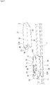
- Figures 1 and 2 show a connecting structure for connecting a wiper blade 1 and a wiper arm 2 according to an embodiment of the present invention.
- Figure 1 shows a state where the wiper blade 1 and the wiper arm 2 are not connected
- Figure 2 shows a state where the wiper blade 1 and the wiper arm 2 are connected.
- the wiper blade 1 includes: a blade main body 11 which is an elongated wiping member; a clip holder 12 fixed on the blade main body 11; and a clip (connecting member) 13 which is rotatably attached to the clip holder 12.
- the clip holder 12 and the clip 13 are formed, for example, with resin molding.
- the clip 13 constitutes a connecting portion of the wiper blade 1.
- the wiper arm 2 is an elongated member adapted for retaining the wiper blade 1.
- the wiper arm 2 includes a proximal end side (not shown) linked with a driving mechanism (not shown) of a wiper system and a distal end side which constitutes a coupling portion 21 adapted to be connected with the clip 3.
- the wiper arm 2 is formed, for example, of metal.
- the coupling portion 21 is a member having a U-shaped cross section and includes a top wall 22 and a pair of side walls 23 disposed on both sides of the top wall 22.
- the clip 13 is fitted into a space surrounded by the top wall 22 and the side walls 23 (housing portion) so that the coupling portion 21 is connected to the wiper blade 1 through the clip 13.
- the clip 13 is introduced into the housing portion from an opening 24 formed at a distal end of the coupling portion 21 and then is fitted into the coupling portion 21 by sliding the coupling portion 21 along the longitudinal direction of the wiper blade 1.
- Claw portions 25 are provided at the lower end edges of the side walls 23 of the coupling portion 21, respectively, to hold the clip 3 by griping it from its underside.
- a locking portion 26 is provided at a distal end 22A (an edge portion of the opening 24) of the top wall 22 of the coupling portion 21 and is a hook-shaped extended portion which can be hooked on the clip 13.
- the locking portion 26 is brought into engagement with a locking recess portion 44 (refer to Figures 3 to 5 ) of a locking piece 40 of the clip 13 so that the coupling portion 21 and the clip portion 13 are locked each other.
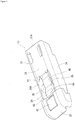
- the clip 13 is a member formed, for example, through integral molding of resin and, as well shown in Figures 3 to 5 , includes: a main body portion 31 having a substantially rectangular parallelepiped shape to which the coupling portion 21 of the wiper arm 2 is installed; and a front end portion 32 which has a streamline shape and is provided at the front side of the main body portion 31.
- the coupling portion 21 is attached to the main body portion 31, the coupling portion 21 is flush with the front end portion 32 to form an integral shape.
- the main body portion 31 includes an upper wall 33 and a pair of side portions 34 provided on both sides of the main body portion 31.
- a rotation shaft portion 35 for attachment to the clip holder 12 is provided on an inside surface 34A of each of the side portions 34.
- the clip 3 is attached to the clip holder 12 to be rotatable about the rotation shaft portions 33.
- the locking piece 40 is formed by cutout on the upper wall 33 of the main body portion 31.
- the locking piece 40 extends forwardly from a proximal end portion 41, which is a fixed end and extends from the proximal end side of the upper wall 33, to a distal end portion 42 which is a free end.
- the locking piece 40 is adapted to be elastically deflectable downwards, as shown in Figure 5 .
- the distal end portion 42 of the locking piece 40 extends in a cutout portion 32A formed on the front end portion 32.
- a protruding portion 43 protruding upwardly is provided at the rear side (proximal end side) of the distal end portion 42 of the locking piece 40 and is disposed adjacent to the distal end portion 42.
- a locking recess portion 44 Formed between the distal end portion 42 and the protruding portion 43 is a locking recess portion 44 within which the locking portion 26 of the coupling portion 21 is engaged.
- the clip 13 When the coupling portion 21 and the clip 13 are connected, the clip 13 is introduced into the opening 24 of the coupling portion 21 from the side facing a rear end 31A of the main body portion 31. The coupling portion 21 is then moved to slide along the longitudinal direction of the wiper blade 1 so that the clip 13 is housed into the coupling portion 21.
- the locking portion 26 of the coupling portion 21 arrives at the protruding portion 43 of the locking piece 40 and depresses the locking piece 40 downwardly.
- the clip 13 is completely housed in the coupling portion 21, and the locking portion 26 fits into the locking recess portion 44 of the locking piece 40 so that the coupling portion 21 is locked on the clip 13.
- the coupling portion 21 is connected to the clip 13 by means of the locking portion 26 provided at the distal end portion 22A of the coupling portion 21 (the top wall 22) of the wiper arm 2. Therefore, any configuration for locking the coupling portion 21 to the clip 13, such as locking hole, does not exist on the outer circumferential surface of the coupling portion 21 (the top wall 22 and the side walls 23).
- the locking portion 26 of the coupling portion 21 is fitted within the locking recess portion 44 of the clip 13. Therefore, the locking portion 26 is inconspicuous. Consequently, the aesthetic appearance of the connecting structure can be improved.
- the connecting portion is the clip 13 is attached to the wiper blade 1 through the clip holder, but the present invention is not limited thereto.
- a connecting member attached directly to the wiper blade may be adopted.
- a connecting portion formed as a part of the wiper blade may be adopted.
Landscapes
- Engineering & Computer Science (AREA)
- Mechanical Engineering (AREA)
- Connection Of Plates (AREA)
- Insertion Pins And Rivets (AREA)
Abstract
Description
- The present invention relates to an improved connecting structure for connecting a wiper blade and a wiper arm in a wiper assembly.
- A wiper assembly used for wiping a surface of a windshield of a motor vehicle is generally constructed by pivotally connecting a wiper blade to a wiper arm which is, in turn, linked with a driving mechanism. A connecting structure of a wiper arm and a wiper blade in a wiper assembly may include a configuration in which a connecting portion of a wiper blade is housed into a box-shaped coupling portion of the wiper arm by sliding the connecting portion along the longitudinal direction of the wiper blade (slot-type connecting structure). For example, Japanese patent disclosure No.
2008-509034 - Patent Literature 1: Japanese Patent disclosure No.
2008-509034 - In such a conventional slot-type connecting structure, the connecting portion is locked (fixed) to the coupling portion by fitting a locking portion (lock button) of the connecting portion into a fitting hole of the coupling portion. In this case, the lock button is provided on a locking piece (for example, a tongue in Patent Literature 1) of the connecting portion, and the lock button is detachably fitted into the fitting hole by deflecting the locking piece..
- Such a conventional structure, however, deteriorates the aesthetic appearance of the wiper assembly, since the locking portion of the connecting portion is exposed from the fitting hole of the coupling portion to the external surface of the coupling portion. In particular, if a resin locking portion of the connecting portion is exposed outside a metallic coupling portion of a metallic wiper arm, the color of the wiper assembly is partly changed at a portion where the locking portion is disposed. As a result, this portion is very conspicuous.
- In view of the foregoing problem, it is an object of the present invention to provide a wiper blade and wiper arm connecting structure in which a wiper blade is connected to a wiper arm by fitting a connecting portion of the wiper blade to a coupling portion of the wiper arm, which improves the aesthetic appearance of a portion where the wiper blade is connected to the wiper arm.
- The present invention provides a wiper blade and wiper arm connecting structure for connecting a wiper blade to a wiper arm by fitting a connecting portion of the wiper blade into a coupling portion of the wiper arm, the wiper arm including an opening for introducing the connecting portion into the coupling portion, the coupling portion including a locking portion disposed adjacent to the opening, the connecting portion including an elastically deformable locking piece, and the locking piece including a locking recess portion into which the locking portion is fitted.
- The coupling portion may include a top wall and a pair of side walls, the opening being disposed at a distal end portion of the coupling portion, the connecting portion being fitted into a housing portion surrounded by the top wall and the side walls through the opening. The locking portion of the coupling portion may be formed at a distal end of the top wall. The locking piece of the connecting portion may be formed on an upper wall of the connecting portion.
- The locking piece may include a protruding portion disposed adjacent to the locking recess portion.
- The present invention provides a wiper blade comprising a connecting portion for connecting the wiper blade to a wiper arm, the connecting portion being adapted to be fitted into a coupling portion of the wiper arm, the connecting portion including an elastically deformable locking piece, and the locking piece including a locking recess portion into which the locking portion is fitted.
- The locking piece may be formed on an upper wall of the connecting portion.
- According to the wiper blade and wiper arm connecting structure or the wiper blade of the present invention, the coupling portion (for example, a coupling portion 21) of the wiper arm (for example, a wiper arm 2) includes the locking portion (for example, a locking portion 26) disposed adjacent to the opening (for example, an opening 24) into which the connecting portion (for example, a clip 13) of the wiper blade (for example, a wiper blade 1) is introduced. Therefore, the configuration for locking the connecting portion and the coupling portion does not exist on the external surface of the coupling portion. Accordingly, the aesthetic appearance of the connecting structure is improved. In addition, the locking portion is fitted into the locking recess portion (for example, a locking recess portion 44) so that the locking portion is inconspicuous. Thus, the aesthetic appearance of the connecting structure is further improved. Moreover, the locking recess portion is provided on the elastically deformable locking piece (for example, a locking piece 40). With this feature, when the connecting portion is installed into the coupling portion, the locking piece can be deflected so that the locking portion can be smoothly fitted into the locking recess portion. Accordingly, the installation can be efficiently carried out.
- The locking portion is provided on the top wall (for example, a top wall 22) of the connecting portion. Accordingly, locking process can be stably carried out at a laterally central portion of the connecting structure.
- The feature that the protruding portion is provided adjacent to the locking recess portion contributes to smooth installation of the connecting portion to the coupling portion, since the locking piece is deformed when the locking portion is in contact with the protruding portion.
-
- [
Figure 1] Figure 1 is a perspective view of a wiper blade and wiper arm connecting structure according to an embodiment of the present invention, illustrating a state where a wiper blade and a wiper arm are not connected. - [
Figure 2] Figure 2 is a perspective view of the wiper blade and wiper arm connecting structure of the embodiment of the present invention, illustrating a state where the wiper blade and the wiper arm are connected. - [
Figure 3] Figure 3 is a perspective view illustrating a clip of the embodiment of the present invention. - [
Figure 4] Figure 4 is a sectional view illustrating the clip of the embodiment of the present invention. - [
Figure 5] Figure 5 is a sectional view of the clip of the embodiment of the present invention, the sectional view illustrating a state where a locking piece deflects downwards. - The present invention will now be described, by way of example, with reference to the accompanying drawings.
-
Figures 1 and2 show a connecting structure for connecting a wiper blade 1 and awiper arm 2 according to an embodiment of the present invention.Figure 1 shows a state where the wiper blade 1 and thewiper arm 2 are not connected, whileFigure 2 shows a state where the wiper blade 1 and thewiper arm 2 are connected. - As shown in the figures, the wiper blade 1 includes: a blade
main body 11 which is an elongated wiping member; aclip holder 12 fixed on the blademain body 11; and a clip (connecting member) 13 which is rotatably attached to theclip holder 12. Theclip holder 12 and theclip 13 are formed, for example, with resin molding. In this embodiment, theclip 13 constitutes a connecting portion of the wiper blade 1. - The
wiper arm 2 is an elongated member adapted for retaining the wiper blade 1. Thewiper arm 2 includes a proximal end side (not shown) linked with a driving mechanism (not shown) of a wiper system and a distal end side which constitutes acoupling portion 21 adapted to be connected with the clip 3. Thewiper arm 2 is formed, for example, of metal. - The
coupling portion 21 is a member having a U-shaped cross section and includes atop wall 22 and a pair ofside walls 23 disposed on both sides of thetop wall 22. Theclip 13 is fitted into a space surrounded by thetop wall 22 and the side walls 23 (housing portion) so that thecoupling portion 21 is connected to the wiper blade 1 through theclip 13. Theclip 13 is introduced into the housing portion from anopening 24 formed at a distal end of thecoupling portion 21 and then is fitted into thecoupling portion 21 by sliding thecoupling portion 21 along the longitudinal direction of the wiper blade 1.Claw portions 25 are provided at the lower end edges of theside walls 23 of thecoupling portion 21, respectively, to hold the clip 3 by griping it from its underside. - A
locking portion 26 is provided at adistal end 22A (an edge portion of the opening 24) of thetop wall 22 of thecoupling portion 21 and is a hook-shaped extended portion which can be hooked on theclip 13. Thelocking portion 26 is brought into engagement with a locking recess portion 44 (refer toFigures 3 to 5 ) of alocking piece 40 of theclip 13 so that thecoupling portion 21 and theclip portion 13 are locked each other. - The
clip 13 is a member formed, for example, through integral molding of resin and, as well shown inFigures 3 to 5 , includes: amain body portion 31 having a substantially rectangular parallelepiped shape to which thecoupling portion 21 of thewiper arm 2 is installed; and afront end portion 32 which has a streamline shape and is provided at the front side of themain body portion 31. When thecoupling portion 21 is attached to themain body portion 31, thecoupling portion 21 is flush with thefront end portion 32 to form an integral shape. - The
main body portion 31 includes anupper wall 33 and a pair ofside portions 34 provided on both sides of themain body portion 31. Arotation shaft portion 35 for attachment to theclip holder 12 is provided on aninside surface 34A of each of theside portions 34. The clip 3 is attached to theclip holder 12 to be rotatable about therotation shaft portions 33. - The
locking piece 40 is formed by cutout on theupper wall 33 of themain body portion 31. Thelocking piece 40 extends forwardly from aproximal end portion 41, which is a fixed end and extends from the proximal end side of theupper wall 33, to adistal end portion 42 which is a free end. Thelocking piece 40 is adapted to be elastically deflectable downwards, as shown inFigure 5 . Thedistal end portion 42 of the lockingpiece 40 extends in acutout portion 32A formed on thefront end portion 32. - A protruding
portion 43 protruding upwardly is provided at the rear side (proximal end side) of thedistal end portion 42 of the lockingpiece 40 and is disposed adjacent to thedistal end portion 42. Formed between thedistal end portion 42 and the protrudingportion 43 is alocking recess portion 44 within which the lockingportion 26 of thecoupling portion 21 is engaged.. - When the
coupling portion 21 and theclip 13 are connected, theclip 13 is introduced into theopening 24 of thecoupling portion 21 from the side facing arear end 31A of themain body portion 31. Thecoupling portion 21 is then moved to slide along the longitudinal direction of the wiper blade 1 so that theclip 13 is housed into thecoupling portion 21. - As the connecting work of introducing the
clip 13 into thecoupling portion 21 proceeds as described above, the lockingportion 26 of thecoupling portion 21 arrives at the protrudingportion 43 of the lockingpiece 40 and depresses the lockingpiece 40 downwardly. As thecoupling portion 21 is moved further from this state, theclip 13 is completely housed in thecoupling portion 21, and the lockingportion 26 fits into thelocking recess portion 44 of the lockingpiece 40 so that thecoupling portion 21 is locked on theclip 13. - As described above, according to the connecting structure of this embodiment, the
coupling portion 21 is connected to theclip 13 by means of the lockingportion 26 provided at thedistal end portion 22A of the coupling portion 21 (the top wall 22) of thewiper arm 2. Therefore, any configuration for locking thecoupling portion 21 to theclip 13, such as locking hole, does not exist on the outer circumferential surface of the coupling portion 21 (thetop wall 22 and the side walls 23). In addition, the lockingportion 26 of thecoupling portion 21 is fitted within thelocking recess portion 44 of theclip 13. Therefore, the lockingportion 26 is inconspicuous. Consequently, the aesthetic appearance of the connecting structure can be improved. - The embodiment of the present invention has been described above, but the present invention is not limited to the embodiment and can be modified as required without departing from a scope defined by the claims. For example, in the illustrated embodiment, the connecting portion is the
clip 13 is attached to the wiper blade 1 through the clip holder, but the present invention is not limited thereto. For example, a connecting member attached directly to the wiper blade may be adopted. Also, a connecting portion formed as a part of the wiper blade may be adopted. -
- 1
- wiper blade
- 2
- wiper arm
- 11
- wiper blade main body
- 12
- clip holder
- 13
- clip
- 21
- coupling portion
- 22
- top wall of coupling portion
- 23
- side wall of coupling portion
- 24
- opening of coupling portion
- 25
- claw portion of coupling portion
- 26
- locking portion of coupling portion
- 31
- main body portion of clip
- 32
- front end portion of clip
- 33
- upper wall of main body portion
- 34
- side portion of main body portion
- 35
- rotation shaft portion
- 40
- locking piece
- 41
- proximal end portion of locking piece
- 42
- distal end portion of locking piece
- 43
- protruding portion of locking piece
- 44
- locking recess portion of locking piece
Claims (5)
- A wiper blade and wiper arm connecting structure for connecting a wiper blade to a wiper arm by fitting a connecting portion of the wiper blade into a coupling portion of the wiper arm,
the wiper arm including an opening for introducing the connecting portion into the coupling portion,
the coupling portion including a locking portion disposed adjacent to the opening,
the connecting portion including an elastically deformable locking piece, and
the locking piece including a locking recess portion into which the locking portion is fitted. - The wiper blade and wiper arm connecting structure according to claim 1,
wherein the coupling portion includes a top wall and a pair of side walls, the opening being disposed at a distal end portion of the coupling portion, the connecting portion being fitted into a housing portion surrounded by the top wall and the side walls through the opening,
wherein the locking portion of the coupling portion is formed at a distal end of the top wall, and
wherein the locking piece of the connecting portion is formed on an upper wall of the connecting portion. - The wiper blade and wiper arm connecting structure according to claim 2,
wherein the locking piece includes a protruding portion disposed adjacent to the locking recess portion. - A wiper blade comprising a connecting portion for connecting the wiper blade to a wiper arm, the connecting portion being adapted to be fitted into a coupling portion of the wiper arm,
the connecting portion including an elastically deformable locking piece, and
the locking piece including a locking recess portion into which the locking portion is fitted. - The wiper blade according to claim 4,
wherein the locking piece is formed on an upper wall of the connecting portion.
Applications Claiming Priority (2)
| Application Number | Priority Date | Filing Date | Title |
|---|---|---|---|
| JP2017057340A JP6359141B1 (en) | 2017-03-23 | 2017-03-23 | Wiper blade and wiper arm connection structure and wiper blade |
| PCT/JP2018/011629 WO2018174230A1 (en) | 2017-03-23 | 2018-03-23 | Coupling structure for wiper blade and wiper arm, and wiper blade |
Publications (3)
| Publication Number | Publication Date |
|---|---|
| EP3604052A1 true EP3604052A1 (en) | 2020-02-05 |
| EP3604052A4 EP3604052A4 (en) | 2020-12-23 |
| EP3604052B1 EP3604052B1 (en) | 2023-05-03 |
Family
ID=62904862
Family Applications (1)
| Application Number | Title | Priority Date | Filing Date |
|---|---|---|---|
| EP18772350.7A Active EP3604052B1 (en) | 2017-03-23 | 2018-03-23 | Coupling structure for wiper blade and wiper arm, and wiper blade |
Country Status (5)
| Country | Link |
|---|---|
| US (1) | US11242038B2 (en) |
| EP (1) | EP3604052B1 (en) |
| JP (1) | JP6359141B1 (en) |
| CN (1) | CN110505986B (en) |
| WO (1) | WO2018174230A1 (en) |
Families Citing this family (2)
| Publication number | Priority date | Publication date | Assignee | Title |
|---|---|---|---|---|
| EP3676135B1 (en) * | 2017-08-28 | 2023-01-11 | Trico Belgium S.A. | A windscreen wiper device |
| US10836360B2 (en) * | 2017-11-03 | 2020-11-17 | Trico Products Corporation | Windscreen wiper device |
Family Cites Families (19)
| Publication number | Priority date | Publication date | Assignee | Title |
|---|---|---|---|---|
| DE10362341B3 (en) * | 2002-11-26 | 2023-02-09 | Valeo Wischersysteme Gmbh | wiper blade |
| EP1623898B1 (en) | 2004-08-03 | 2007-12-12 | Federal-Mogul S.A. | A windscreen wiper device |
| CA2541641C (en) * | 2005-04-04 | 2014-02-11 | Trico Products Corporation | Wiper coupler and wiper assembly incorporating same |
| CN201362242Y (en) * | 2009-03-10 | 2009-12-16 | 厦门市美途汽车配件有限公司 | Split type windshield wiper connecting device |
| JP2013505879A (en) * | 2009-09-29 | 2013-02-21 | シィエィピィ コーポレーション | Multi adapter for car wiper |
| KR100959035B1 (en) | 2010-02-11 | 2010-05-20 | 에이디엠이십일 주식회사 | Device for connecting a wiper blade to a wiper arm |
| DE102011001688A1 (en) * | 2011-03-31 | 2012-10-04 | Valeo Systèmes d'Essuyage | Wiper blade and wiper device for cleaning vehicle windows |
| CN202115477U (en) * | 2011-06-17 | 2012-01-18 | 宁波鑫海爱多汽车雨刷制造有限公司 | Frameless wiper |
| JP5940927B2 (en) * | 2011-09-26 | 2016-06-29 | アスモ株式会社 | Wiper blade |
| JP5833389B2 (en) * | 2011-09-15 | 2015-12-16 | アスモ株式会社 | Wiper blade and vehicle wiper |
| US20130067675A1 (en) | 2011-09-20 | 2013-03-21 | Unipoint Electric Manufacturing Co., Ltd. | Windshield Wiper Connector and Windshield Wiper Connection Assembly |
| CN203020277U (en) * | 2012-12-17 | 2013-06-26 | 许宏龙 | Windshield wiper |
| US9260084B2 (en) | 2013-01-03 | 2016-02-16 | Trico Products Corporation | Wiper coupler adapter and wiper assembly incorporating same |
| FR3006649B1 (en) * | 2013-06-10 | 2016-09-02 | Valeo Systemes Dessuyage | DEVICE FOR FASTENING A WIPER BLADE |
| JP6293441B2 (en) * | 2013-09-05 | 2018-03-14 | アスモ株式会社 | Wiper blade and wiper |
| DE102013019805B4 (en) * | 2013-11-27 | 2022-06-15 | Mercedes-Benz Group AG | Connection arrangement for connecting a wiper blade to a wiper arm, and wiper blade and wiper arm for producing such a connection arrangement |
| WO2016061461A1 (en) * | 2014-10-17 | 2016-04-21 | Federal-Mogul Motorparts Corporation | Windscreen wiper device |
| US10071712B2 (en) * | 2014-12-23 | 2018-09-11 | Trico Products Corporation | Wiper adapter and wiper assembly incorporating the same |
| CN104890639A (en) * | 2015-05-13 | 2015-09-09 | 丹阳镇威汽配有限公司 | Multifunctional sheath mechanism for windshield wiper |
-
2017
- 2017-03-23 JP JP2017057340A patent/JP6359141B1/en active Active
-
2018
- 2018-03-23 CN CN201880020218.XA patent/CN110505986B/en active Active
- 2018-03-23 EP EP18772350.7A patent/EP3604052B1/en active Active
- 2018-03-23 WO PCT/JP2018/011629 patent/WO2018174230A1/en not_active Ceased
- 2018-03-23 US US16/496,711 patent/US11242038B2/en active Active
Also Published As
| Publication number | Publication date |
|---|---|
| JP2018158665A (en) | 2018-10-11 |
| CN110505986B (en) | 2023-05-12 |
| JP6359141B1 (en) | 2018-07-18 |
| CN110505986A (en) | 2019-11-26 |
| WO2018174230A1 (en) | 2018-09-27 |
| US11242038B2 (en) | 2022-02-08 |
| EP3604052A4 (en) | 2020-12-23 |
| EP3604052B1 (en) | 2023-05-03 |
| US20200023813A1 (en) | 2020-01-23 |
Similar Documents
| Publication | Publication Date | Title |
|---|---|---|
| US10077025B2 (en) | Windscreen wiper adapter with safety position | |
| US11465691B2 (en) | Hatch door with mechanically secured rear and side spoiler connection | |
| CN101239603A (en) | door lining | |
| US11242038B2 (en) | Wiper blade and wiper arm connecting structure and wiper blade | |
| US10486651B2 (en) | Adapter for a motor vehicle windscreen wiper | |
| CN107054301A (en) | Adapter for motor vehicles windscreen wiper | |
| US10059309B2 (en) | End fitting with play compensation for wiper | |
| JP5971526B2 (en) | Lock structure for vehicle door trim | |
| CN107009857A (en) | Rear tailgate | |
| US20180086187A1 (en) | Cowl top cover | |
| CN112849273A (en) | Vehicle front structure | |
| US20170120872A1 (en) | Adapter for a motor vehicle windscreen wiper | |
| JP3693966B2 (en) | Mounting adapter for connectors | |
| JP2007030834A (en) | Fender cover structure | |
| JPH09210030A (en) | Hinge collar | |
| CN116613019A (en) | Switching device | |
| JP3690153B2 (en) | Connecting structure by fitting claws of automobile interior parts | |
| US11124157B2 (en) | Undetachable end piece for a wiper blade | |
| JP3519821B2 (en) | Belt molding | |
| JP5176425B2 (en) | Vehicle door sash molding | |
| KR101613700B1 (en) | Connector having grommet | |
| JP6550122B2 (en) | Coupling structure of wiper arm and wiper blade | |
| JP2003335216A (en) | Locking device of seat belt attaching-detaching metal fitting | |
| JPH11208276A (en) | Installation structure for switch panel of vehicle arm rest | |
| JP6166630B2 (en) | Vehicle door |
Legal Events
| Date | Code | Title | Description |
|---|---|---|---|
| STAA | Information on the status of an ep patent application or granted ep patent |
Free format text: STATUS: THE INTERNATIONAL PUBLICATION HAS BEEN MADE |
|
| PUAI | Public reference made under article 153(3) epc to a published international application that has entered the european phase |
Free format text: ORIGINAL CODE: 0009012 |
|
| STAA | Information on the status of an ep patent application or granted ep patent |
Free format text: STATUS: REQUEST FOR EXAMINATION WAS MADE |
|
| 17P | Request for examination filed |
Effective date: 20191018 |
|
| AK | Designated contracting states |
Kind code of ref document: A1 Designated state(s): AL AT BE BG CH CY CZ DE DK EE ES FI FR GB GR HR HU IE IS IT LI LT LU LV MC MK MT NL NO PL PT RO RS SE SI SK SM TR |
|
| AX | Request for extension of the european patent |
Extension state: BA ME |
|
| RAP1 | Party data changed (applicant data changed or rights of an application transferred) |
Owner name: DENSO WIPER SYSTEMS, INC. |
|
| DAV | Request for validation of the european patent (deleted) | ||
| DAX | Request for extension of the european patent (deleted) | ||
| A4 | Supplementary search report drawn up and despatched |
Effective date: 20201119 |
|
| RIC1 | Information provided on ipc code assigned before grant |
Ipc: B60S 1/38 20060101ALI20201113BHEP Ipc: B60S 1/40 20060101AFI20201113BHEP |
|
| STAA | Information on the status of an ep patent application or granted ep patent |
Free format text: STATUS: EXAMINATION IS IN PROGRESS |
|
| 17Q | First examination report despatched |
Effective date: 20211105 |
|
| GRAP | Despatch of communication of intention to grant a patent |
Free format text: ORIGINAL CODE: EPIDOSNIGR1 |
|
| STAA | Information on the status of an ep patent application or granted ep patent |
Free format text: STATUS: GRANT OF PATENT IS INTENDED |
|
| INTG | Intention to grant announced |
Effective date: 20221115 |
|
| GRAS | Grant fee paid |
Free format text: ORIGINAL CODE: EPIDOSNIGR3 |
|
| GRAA | (expected) grant |
Free format text: ORIGINAL CODE: 0009210 |
|
| STAA | Information on the status of an ep patent application or granted ep patent |
Free format text: STATUS: THE PATENT HAS BEEN GRANTED |
|
| AK | Designated contracting states |
Kind code of ref document: B1 Designated state(s): AL AT BE BG CH CY CZ DE DK EE ES FI FR GB GR HR HU IE IS IT LI LT LU LV MC MK MT NL NO PL PT RO RS SE SI SK SM TR |
|
| REG | Reference to a national code |
Ref country code: GB Ref legal event code: FG4D |
|
| REG | Reference to a national code |
Ref country code: DE Ref legal event code: R096 Ref document number: 602018049265 Country of ref document: DE |
|
| REG | Reference to a national code |
Ref country code: AT Ref legal event code: REF Ref document number: 1564330 Country of ref document: AT Kind code of ref document: T Effective date: 20230515 Ref country code: CH Ref legal event code: EP |
|
| REG | Reference to a national code |
Ref country code: IE Ref legal event code: FG4D |
|
| REG | Reference to a national code |
Ref country code: LT Ref legal event code: MG9D |
|
| REG | Reference to a national code |
Ref country code: NL Ref legal event code: MP Effective date: 20230503 |
|
| REG | Reference to a national code |
Ref country code: AT Ref legal event code: MK05 Ref document number: 1564330 Country of ref document: AT Kind code of ref document: T Effective date: 20230503 |
|
| PG25 | Lapsed in a contracting state [announced via postgrant information from national office to epo] |
Ref country code: SE Free format text: LAPSE BECAUSE OF FAILURE TO SUBMIT A TRANSLATION OF THE DESCRIPTION OR TO PAY THE FEE WITHIN THE PRESCRIBED TIME-LIMIT Effective date: 20230503 Ref country code: PT Free format text: LAPSE BECAUSE OF FAILURE TO SUBMIT A TRANSLATION OF THE DESCRIPTION OR TO PAY THE FEE WITHIN THE PRESCRIBED TIME-LIMIT Effective date: 20230904 Ref country code: NO Free format text: LAPSE BECAUSE OF FAILURE TO SUBMIT A TRANSLATION OF THE DESCRIPTION OR TO PAY THE FEE WITHIN THE PRESCRIBED TIME-LIMIT Effective date: 20230803 Ref country code: NL Free format text: LAPSE BECAUSE OF FAILURE TO SUBMIT A TRANSLATION OF THE DESCRIPTION OR TO PAY THE FEE WITHIN THE PRESCRIBED TIME-LIMIT Effective date: 20230503 Ref country code: ES Free format text: LAPSE BECAUSE OF FAILURE TO SUBMIT A TRANSLATION OF THE DESCRIPTION OR TO PAY THE FEE WITHIN THE PRESCRIBED TIME-LIMIT Effective date: 20230503 Ref country code: AT Free format text: LAPSE BECAUSE OF FAILURE TO SUBMIT A TRANSLATION OF THE DESCRIPTION OR TO PAY THE FEE WITHIN THE PRESCRIBED TIME-LIMIT Effective date: 20230503 |
|
| PG25 | Lapsed in a contracting state [announced via postgrant information from national office to epo] |
Ref country code: RS Free format text: LAPSE BECAUSE OF FAILURE TO SUBMIT A TRANSLATION OF THE DESCRIPTION OR TO PAY THE FEE WITHIN THE PRESCRIBED TIME-LIMIT Effective date: 20230503 Ref country code: PL Free format text: LAPSE BECAUSE OF FAILURE TO SUBMIT A TRANSLATION OF THE DESCRIPTION OR TO PAY THE FEE WITHIN THE PRESCRIBED TIME-LIMIT Effective date: 20230503 Ref country code: LV Free format text: LAPSE BECAUSE OF FAILURE TO SUBMIT A TRANSLATION OF THE DESCRIPTION OR TO PAY THE FEE WITHIN THE PRESCRIBED TIME-LIMIT Effective date: 20230503 Ref country code: LT Free format text: LAPSE BECAUSE OF FAILURE TO SUBMIT A TRANSLATION OF THE DESCRIPTION OR TO PAY THE FEE WITHIN THE PRESCRIBED TIME-LIMIT Effective date: 20230503 Ref country code: IS Free format text: LAPSE BECAUSE OF FAILURE TO SUBMIT A TRANSLATION OF THE DESCRIPTION OR TO PAY THE FEE WITHIN THE PRESCRIBED TIME-LIMIT Effective date: 20230903 Ref country code: HR Free format text: LAPSE BECAUSE OF FAILURE TO SUBMIT A TRANSLATION OF THE DESCRIPTION OR TO PAY THE FEE WITHIN THE PRESCRIBED TIME-LIMIT Effective date: 20230503 Ref country code: GR Free format text: LAPSE BECAUSE OF FAILURE TO SUBMIT A TRANSLATION OF THE DESCRIPTION OR TO PAY THE FEE WITHIN THE PRESCRIBED TIME-LIMIT Effective date: 20230804 |
|
| PG25 | Lapsed in a contracting state [announced via postgrant information from national office to epo] |
Ref country code: FI Free format text: LAPSE BECAUSE OF FAILURE TO SUBMIT A TRANSLATION OF THE DESCRIPTION OR TO PAY THE FEE WITHIN THE PRESCRIBED TIME-LIMIT Effective date: 20230503 |
|
| PG25 | Lapsed in a contracting state [announced via postgrant information from national office to epo] |
Ref country code: SK Free format text: LAPSE BECAUSE OF FAILURE TO SUBMIT A TRANSLATION OF THE DESCRIPTION OR TO PAY THE FEE WITHIN THE PRESCRIBED TIME-LIMIT Effective date: 20230503 |
|
| PG25 | Lapsed in a contracting state [announced via postgrant information from national office to epo] |
Ref country code: SM Free format text: LAPSE BECAUSE OF FAILURE TO SUBMIT A TRANSLATION OF THE DESCRIPTION OR TO PAY THE FEE WITHIN THE PRESCRIBED TIME-LIMIT Effective date: 20230503 Ref country code: SK Free format text: LAPSE BECAUSE OF FAILURE TO SUBMIT A TRANSLATION OF THE DESCRIPTION OR TO PAY THE FEE WITHIN THE PRESCRIBED TIME-LIMIT Effective date: 20230503 Ref country code: RO Free format text: LAPSE BECAUSE OF FAILURE TO SUBMIT A TRANSLATION OF THE DESCRIPTION OR TO PAY THE FEE WITHIN THE PRESCRIBED TIME-LIMIT Effective date: 20230503 Ref country code: EE Free format text: LAPSE BECAUSE OF FAILURE TO SUBMIT A TRANSLATION OF THE DESCRIPTION OR TO PAY THE FEE WITHIN THE PRESCRIBED TIME-LIMIT Effective date: 20230503 Ref country code: DK Free format text: LAPSE BECAUSE OF FAILURE TO SUBMIT A TRANSLATION OF THE DESCRIPTION OR TO PAY THE FEE WITHIN THE PRESCRIBED TIME-LIMIT Effective date: 20230503 Ref country code: CZ Free format text: LAPSE BECAUSE OF FAILURE TO SUBMIT A TRANSLATION OF THE DESCRIPTION OR TO PAY THE FEE WITHIN THE PRESCRIBED TIME-LIMIT Effective date: 20230503 |
|
| REG | Reference to a national code |
Ref country code: DE Ref legal event code: R097 Ref document number: 602018049265 Country of ref document: DE |
|
| PLBE | No opposition filed within time limit |
Free format text: ORIGINAL CODE: 0009261 |
|
| STAA | Information on the status of an ep patent application or granted ep patent |
Free format text: STATUS: NO OPPOSITION FILED WITHIN TIME LIMIT |
|
| 26N | No opposition filed |
Effective date: 20240206 |
|
| PG25 | Lapsed in a contracting state [announced via postgrant information from national office to epo] |
Ref country code: SI Free format text: LAPSE BECAUSE OF FAILURE TO SUBMIT A TRANSLATION OF THE DESCRIPTION OR TO PAY THE FEE WITHIN THE PRESCRIBED TIME-LIMIT Effective date: 20230503 |
|
| PG25 | Lapsed in a contracting state [announced via postgrant information from national office to epo] |
Ref country code: SI Free format text: LAPSE BECAUSE OF FAILURE TO SUBMIT A TRANSLATION OF THE DESCRIPTION OR TO PAY THE FEE WITHIN THE PRESCRIBED TIME-LIMIT Effective date: 20230503 Ref country code: IT Free format text: LAPSE BECAUSE OF FAILURE TO SUBMIT A TRANSLATION OF THE DESCRIPTION OR TO PAY THE FEE WITHIN THE PRESCRIBED TIME-LIMIT Effective date: 20230503 |
|
| REG | Reference to a national code |
Ref country code: CH Ref legal event code: PL |
|
| PG25 | Lapsed in a contracting state [announced via postgrant information from national office to epo] |
Ref country code: BG Free format text: LAPSE BECAUSE OF FAILURE TO SUBMIT A TRANSLATION OF THE DESCRIPTION OR TO PAY THE FEE WITHIN THE PRESCRIBED TIME-LIMIT Effective date: 20230503 |
|
| PG25 | Lapsed in a contracting state [announced via postgrant information from national office to epo] |
Ref country code: LU Free format text: LAPSE BECAUSE OF NON-PAYMENT OF DUE FEES Effective date: 20240323 |
|
| PG25 | Lapsed in a contracting state [announced via postgrant information from national office to epo] |
Ref country code: MC Free format text: LAPSE BECAUSE OF FAILURE TO SUBMIT A TRANSLATION OF THE DESCRIPTION OR TO PAY THE FEE WITHIN THE PRESCRIBED TIME-LIMIT Effective date: 20230503 |
|
| GBPC | Gb: european patent ceased through non-payment of renewal fee |
Effective date: 20240323 |
|
| PG25 | Lapsed in a contracting state [announced via postgrant information from national office to epo] |
Ref country code: MC Free format text: LAPSE BECAUSE OF FAILURE TO SUBMIT A TRANSLATION OF THE DESCRIPTION OR TO PAY THE FEE WITHIN THE PRESCRIBED TIME-LIMIT Effective date: 20230503 Ref country code: LU Free format text: LAPSE BECAUSE OF NON-PAYMENT OF DUE FEES Effective date: 20240323 Ref country code: BG Free format text: LAPSE BECAUSE OF FAILURE TO SUBMIT A TRANSLATION OF THE DESCRIPTION OR TO PAY THE FEE WITHIN THE PRESCRIBED TIME-LIMIT Effective date: 20230503 |
|
| REG | Reference to a national code |
Ref country code: BE Ref legal event code: MM Effective date: 20240331 |
|
| PG25 | Lapsed in a contracting state [announced via postgrant information from national office to epo] |
Ref country code: BE Free format text: LAPSE BECAUSE OF NON-PAYMENT OF DUE FEES Effective date: 20240331 |
|
| PG25 | Lapsed in a contracting state [announced via postgrant information from national office to epo] |
Ref country code: GB Free format text: LAPSE BECAUSE OF NON-PAYMENT OF DUE FEES Effective date: 20240323 |
|
| PG25 | Lapsed in a contracting state [announced via postgrant information from national office to epo] |
Ref country code: FR Free format text: LAPSE BECAUSE OF NON-PAYMENT OF DUE FEES Effective date: 20240331 |
|
| PG25 | Lapsed in a contracting state [announced via postgrant information from national office to epo] |
Ref country code: IE Free format text: LAPSE BECAUSE OF NON-PAYMENT OF DUE FEES Effective date: 20240323 |
|
| PG25 | Lapsed in a contracting state [announced via postgrant information from national office to epo] |
Ref country code: IE Free format text: LAPSE BECAUSE OF NON-PAYMENT OF DUE FEES Effective date: 20240323 Ref country code: GB Free format text: LAPSE BECAUSE OF NON-PAYMENT OF DUE FEES Effective date: 20240323 Ref country code: FR Free format text: LAPSE BECAUSE OF NON-PAYMENT OF DUE FEES Effective date: 20240331 Ref country code: BE Free format text: LAPSE BECAUSE OF NON-PAYMENT OF DUE FEES Effective date: 20240331 Ref country code: CH Free format text: LAPSE BECAUSE OF NON-PAYMENT OF DUE FEES Effective date: 20240331 |
|
| PG25 | Lapsed in a contracting state [announced via postgrant information from national office to epo] |
Ref country code: CY Free format text: LAPSE BECAUSE OF FAILURE TO SUBMIT A TRANSLATION OF THE DESCRIPTION OR TO PAY THE FEE WITHIN THE PRESCRIBED TIME-LIMIT; INVALID AB INITIO Effective date: 20180323 |
|
| PG25 | Lapsed in a contracting state [announced via postgrant information from national office to epo] |
Ref country code: HU Free format text: LAPSE BECAUSE OF FAILURE TO SUBMIT A TRANSLATION OF THE DESCRIPTION OR TO PAY THE FEE WITHIN THE PRESCRIBED TIME-LIMIT; INVALID AB INITIO Effective date: 20180323 |
|
| PG25 | Lapsed in a contracting state [announced via postgrant information from national office to epo] |
Ref country code: TR Free format text: LAPSE BECAUSE OF FAILURE TO SUBMIT A TRANSLATION OF THE DESCRIPTION OR TO PAY THE FEE WITHIN THE PRESCRIBED TIME-LIMIT Effective date: 20230503 |
|
| PGFP | Annual fee paid to national office [announced via postgrant information from national office to epo] |
Ref country code: DE Payment date: 20260319 Year of fee payment: 9 |