EP3604047B1 - Passenger protection device - Google Patents
Passenger protection device Download PDFInfo
- Publication number
- EP3604047B1 EP3604047B1 EP18776327.1A EP18776327A EP3604047B1 EP 3604047 B1 EP3604047 B1 EP 3604047B1 EP 18776327 A EP18776327 A EP 18776327A EP 3604047 B1 EP3604047 B1 EP 3604047B1
- Authority
- EP
- European Patent Office
- Prior art keywords
- chamber
- deployed
- airbag
- vehicle
- frame
- Prior art date
- Legal status (The legal status is an assumption and is not a legal conclusion. Google has not performed a legal analysis and makes no representation as to the accuracy of the status listed.)
- Active
Links
Images


Classifications
-
- B—PERFORMING OPERATIONS; TRANSPORTING
- B60—VEHICLES IN GENERAL
- B60R—VEHICLES, VEHICLE FITTINGS, OR VEHICLE PARTS, NOT OTHERWISE PROVIDED FOR
- B60R21/00—Arrangements or fittings on vehicles for protecting or preventing injuries to occupants or pedestrians in case of accidents or other traffic risks
- B60R21/02—Occupant safety arrangements or fittings, e.g. crash pads
- B60R21/16—Inflatable occupant restraints or confinements designed to inflate upon impact or impending impact, e.g. air bags
- B60R21/20—Arrangements for storing inflatable members in their non-use or deflated condition; Arrangement or mounting of air bag modules or components
- B60R21/207—Arrangements for storing inflatable members in their non-use or deflated condition; Arrangement or mounting of air bag modules or components in vehicle seats
-
- B—PERFORMING OPERATIONS; TRANSPORTING
- B60—VEHICLES IN GENERAL
- B60R—VEHICLES, VEHICLE FITTINGS, OR VEHICLE PARTS, NOT OTHERWISE PROVIDED FOR
- B60R21/00—Arrangements or fittings on vehicles for protecting or preventing injuries to occupants or pedestrians in case of accidents or other traffic risks
- B60R21/02—Occupant safety arrangements or fittings, e.g. crash pads
- B60R21/16—Inflatable occupant restraints or confinements designed to inflate upon impact or impending impact, e.g. air bags
- B60R21/23—Inflatable members
- B60R21/231—Inflatable members characterised by their shape, construction or spatial configuration
- B60R21/23138—Inflatable members characterised by their shape, construction or spatial configuration specially adapted for side protection
-
- B—PERFORMING OPERATIONS; TRANSPORTING
- B60—VEHICLES IN GENERAL
- B60R—VEHICLES, VEHICLE FITTINGS, OR VEHICLE PARTS, NOT OTHERWISE PROVIDED FOR
- B60R21/00—Arrangements or fittings on vehicles for protecting or preventing injuries to occupants or pedestrians in case of accidents or other traffic risks
- B60R21/02—Occupant safety arrangements or fittings, e.g. crash pads
- B60R21/16—Inflatable occupant restraints or confinements designed to inflate upon impact or impending impact, e.g. air bags
- B60R21/23—Inflatable members
- B60R21/231—Inflatable members characterised by their shape, construction or spatial configuration
- B60R21/233—Inflatable members characterised by their shape, construction or spatial configuration comprising a plurality of individual compartments; comprising two or more bag-like members, one within the other
-
- B—PERFORMING OPERATIONS; TRANSPORTING
- B60—VEHICLES IN GENERAL
- B60R—VEHICLES, VEHICLE FITTINGS, OR VEHICLE PARTS, NOT OTHERWISE PROVIDED FOR
- B60R21/00—Arrangements or fittings on vehicles for protecting or preventing injuries to occupants or pedestrians in case of accidents or other traffic risks
- B60R21/02—Occupant safety arrangements or fittings, e.g. crash pads
- B60R21/16—Inflatable occupant restraints or confinements designed to inflate upon impact or impending impact, e.g. air bags
- B60R21/23—Inflatable members
- B60R21/239—Inflatable members characterised by their venting means
-
- B—PERFORMING OPERATIONS; TRANSPORTING
- B60—VEHICLES IN GENERAL
- B60R—VEHICLES, VEHICLE FITTINGS, OR VEHICLE PARTS, NOT OTHERWISE PROVIDED FOR
- B60R21/00—Arrangements or fittings on vehicles for protecting or preventing injuries to occupants or pedestrians in case of accidents or other traffic risks
- B60R21/02—Occupant safety arrangements or fittings, e.g. crash pads
- B60R21/16—Inflatable occupant restraints or confinements designed to inflate upon impact or impending impact, e.g. air bags
- B60R21/26—Inflatable occupant restraints or confinements designed to inflate upon impact or impending impact, e.g. air bags characterised by the inflation fluid source or means to control inflation fluid flow
- B60R21/264—Inflatable occupant restraints or confinements designed to inflate upon impact or impending impact, e.g. air bags characterised by the inflation fluid source or means to control inflation fluid flow using instantaneous generation of gas, e.g. pyrotechnic
-
- B—PERFORMING OPERATIONS; TRANSPORTING
- B60—VEHICLES IN GENERAL
- B60R—VEHICLES, VEHICLE FITTINGS, OR VEHICLE PARTS, NOT OTHERWISE PROVIDED FOR
- B60R21/00—Arrangements or fittings on vehicles for protecting or preventing injuries to occupants or pedestrians in case of accidents or other traffic risks
- B60R2021/0002—Type of accident
- B60R2021/0006—Lateral collision
-
- B—PERFORMING OPERATIONS; TRANSPORTING
- B60—VEHICLES IN GENERAL
- B60R—VEHICLES, VEHICLE FITTINGS, OR VEHICLE PARTS, NOT OTHERWISE PROVIDED FOR
- B60R21/00—Arrangements or fittings on vehicles for protecting or preventing injuries to occupants or pedestrians in case of accidents or other traffic risks
- B60R21/02—Occupant safety arrangements or fittings, e.g. crash pads
- B60R21/16—Inflatable occupant restraints or confinements designed to inflate upon impact or impending impact, e.g. air bags
- B60R21/23—Inflatable members
- B60R21/231—Inflatable members characterised by their shape, construction or spatial configuration
- B60R21/23138—Inflatable members characterised by their shape, construction or spatial configuration specially adapted for side protection
- B60R2021/23146—Inflatable members characterised by their shape, construction or spatial configuration specially adapted for side protection seat mounted
-
- B—PERFORMING OPERATIONS; TRANSPORTING
- B60—VEHICLES IN GENERAL
- B60R—VEHICLES, VEHICLE FITTINGS, OR VEHICLE PARTS, NOT OTHERWISE PROVIDED FOR
- B60R21/00—Arrangements or fittings on vehicles for protecting or preventing injuries to occupants or pedestrians in case of accidents or other traffic risks
- B60R21/02—Occupant safety arrangements or fittings, e.g. crash pads
- B60R21/16—Inflatable occupant restraints or confinements designed to inflate upon impact or impending impact, e.g. air bags
- B60R21/23—Inflatable members
- B60R21/231—Inflatable members characterised by their shape, construction or spatial configuration
- B60R21/233—Inflatable members characterised by their shape, construction or spatial configuration comprising a plurality of individual compartments; comprising two or more bag-like members, one within the other
- B60R2021/23308—Inflatable members characterised by their shape, construction or spatial configuration comprising a plurality of individual compartments; comprising two or more bag-like members, one within the other the individual compartments defining the external shape of the bag
-
- B—PERFORMING OPERATIONS; TRANSPORTING
- B60—VEHICLES IN GENERAL
- B60R—VEHICLES, VEHICLE FITTINGS, OR VEHICLE PARTS, NOT OTHERWISE PROVIDED FOR
- B60R21/00—Arrangements or fittings on vehicles for protecting or preventing injuries to occupants or pedestrians in case of accidents or other traffic risks
- B60R21/02—Occupant safety arrangements or fittings, e.g. crash pads
- B60R21/16—Inflatable occupant restraints or confinements designed to inflate upon impact or impending impact, e.g. air bags
- B60R21/23—Inflatable members
- B60R21/231—Inflatable members characterised by their shape, construction or spatial configuration
- B60R21/2334—Expansion control features
- B60R21/2338—Tethers
- B60R2021/23386—External tether means
-
- B—PERFORMING OPERATIONS; TRANSPORTING
- B60—VEHICLES IN GENERAL
- B60R—VEHICLES, VEHICLE FITTINGS, OR VEHICLE PARTS, NOT OTHERWISE PROVIDED FOR
- B60R21/00—Arrangements or fittings on vehicles for protecting or preventing injuries to occupants or pedestrians in case of accidents or other traffic risks
- B60R21/02—Occupant safety arrangements or fittings, e.g. crash pads
- B60R21/16—Inflatable occupant restraints or confinements designed to inflate upon impact or impending impact, e.g. air bags
- B60R21/26—Inflatable occupant restraints or confinements designed to inflate upon impact or impending impact, e.g. air bags characterised by the inflation fluid source or means to control inflation fluid flow
- B60R21/264—Inflatable occupant restraints or confinements designed to inflate upon impact or impending impact, e.g. air bags characterised by the inflation fluid source or means to control inflation fluid flow using instantaneous generation of gas, e.g. pyrotechnic
- B60R2021/2642—Inflatable occupant restraints or confinements designed to inflate upon impact or impending impact, e.g. air bags characterised by the inflation fluid source or means to control inflation fluid flow using instantaneous generation of gas, e.g. pyrotechnic comprising a plurality of combustion chambers or sub-chambers
Definitions
- the present invention relates to a passenger protection apparatus including a side airbag apparatus which protects passengers when deployed on the seat side of a vehicle.
- airbags In order to protect passengers when a vehicle accident occurs, it is well known that vehicles are equipped with one or more airbags.
- These airbags include various forms such as: a so-called driver airbag which is expanded from the vicinity of the steering wheel of an automobile so as protect the driver; a curtain airbag which is deployed downward inside the window of an automobile so as to protect passengers during collisions in the transverse direction of a vehicle, overturning, and rollover accidents; and a side airbag apparatus which is deployed on the side (seat side) of passengers so as to protect the passenger upon impact in the transverse direction of a vehicle.
- the present invention relates to a side airbag apparatus provided in a vehicle seat.
- the side airbag apparatus described in the below mentioned Patent Document 1 includes a main airbag along with an auxiliary airbag.
- the auxiliary airbag prior to the main airbag, the auxiliary airbag is expanded and deployed to restrain passengers at an early stage.
- a side airbag apparatus including the auxiliary airbag as well as the main airbag is proposed. With such a side airbag apparatus, there is great restraint in the installation region, resulting in a strong demand for size reduction of the apparatus.
- EP3050761 A shows a passenger protection apparatus according to the preamble of claim 1.
- the present invention has been created in view of the abovementioned problem, with an object of providing a passenger protection apparatus which includes a side airbag apparatus capable of quickly and properly restraining a passenger. Moreover, another object is to provide a passenger protection apparatus including a side airbag apparatus which contributes to the size reduction of the apparatus.
- the present invention is applied to a passenger protection apparatus, including: a vehicle seat having a seat cushion forming a seating face along with a seat back forming a backrest; and a side airbag apparatus housed in this seat.
- the seat back includes a side support part which swells in the vehicle traveling direction (vehicle front) on the vehicle width direction side (end).
- a side frame part having a frame side wall part (which extends in the vehicle traveling direction when the horizontal cross section is seen from above) is arranged inside the side support part.
- the side airbag apparatus includes: an airbag which restrains a passenger when expanded and deployed; and an inflator supplying expansion gas to the airbag,
- the airbag includes: a first chamber which houses the inflator and is deployed outside in the vehicle width direction of the frame side wall part; and a second chamber which is deployed inside in the vehicle width direction of the frame side wall part.
- the first chamber is deployed such that at least a portion thereof, as seen from the vehicle side, overlaps the frame side wall part.
- the rear end part of an expanding region of the second chamber, as seen from the vehicle side is formed in front of the rear end part of the first chamber.
- the inside in the vehicle width direction of the frame side wall part denotes the center side (passenger side) of the seat
- the outside in the vehicle width direction of the frame side wall part denotes the outside (door side, center console side) in the transverse direction of the seat.
- the first chamber C1 is deployed outside the side support part in the initial stage of operating the airbag apparatus.
- the first chamber is assuredly deployed such that the frame side wall part receives the reaction force of the first chamber.
- the second chamber is deployed so as to quickly restrain a passenger from moving to the outside in the vehicle width direction.
- the surface on the frame side of the second chamber is supported by both this frame side wall part and the first chamber (which has already started to be deployed) or only by the first chamber, with both the frame side wall part and the first chamber, or just the first chamber, receiving the reaction force when the second chamber is deployed. Therefore, when the passenger enters the second chamber, the pressure from the passenger can be received by the frame side wall part, making it possible to assuredly restrain the passenger in the seat center direction.
- the first chamber and the second chamber can be provided so as to hold the frame side wall part.
- Such a configuration allows the first chamber to be assuredly deployed outside in the vehicle width direction of the frame side wall part, in addition to allowing the second chamber to be assuredly deployed inside in the vehicle width direction of the frame side wall part, thereby easily controlling the deployed position of each chamber.
- the second chamber can be deployed, as seen from the vehicle side, so as not to overlap the frame side wall part.
- the shape of the overall airbag is advantageously more likely to be widened forward.
- At least one first internal vent hole is preferably formed at the boundary part between the first chamber and the second chamber such that the gas inside the first chamber flows into the second chamber. The presence of the first internal vent hole allows the expansion gas to be quickly filled into the overall airbag.
- the first chamber and the second chamber can be configured as a single chamber. In this case, the number of panels constituting the airbag can be decreased to simplify the overall panel structure.
- the second chamber can be sectioned into a front chamber part and a rear chamber part, wherein at least one second internal vent hole can be provided in this section part.
- the front end part of the second chamber can be disposed in front of the front end part of the first chamber. In this way, when the front end of the second chamber on the side near the passenger moves forward, for example, a passenger who is seated while bent forward can be restrained, enabling the restraint range of the passenger to be widened.
- the passenger protection apparatus can further include a third chamber coupled to this first chamber on the side of the first chamber opposite the second chamber.
- At least one third internal vent hole can be formed at the boundary part between the first chamber and the third chamber such that the gas inside the first chamber flows into the third chamber.
- the expansion gas branched from the first chamber is separately fed into the second chamber and the third chamber, respectively, thereby contributing to the quick deployment of the second chamber and the third chamber.
- the front end part of the third chamber can be configured so as to be disposed in front of the front end parts of the first chamber and the second chamber.
- the width in the anteroposterior direction can be relatively easily increased.
- the third chamber can be sectioned into a front chamber part and a rear chamber part, wherein at least one fourth internal vent hole can be provided in this section part.
- the width in the anteroposterior direction can be further increased.
- the passenger protection apparatus can further include a fourth chamber coupled to the side face of the second chamber in front of the first chamber.
- at least one fifth internal vent hole can be formed at the boundary part between the second chamber and the fourth chamber such that the gas inside the second chamber flows into the fourth chamber.
- At least one sixth vent hole can be formed at the boundary part between the fourth chamber and the first chamber such that the gas inside the first chamber flows into the fourth chamber.
- the rear part of the fourth chamber can be provided outside the side frame so as to cover the outside in the vehicle width direction of the second chamber, such that the first chamber can function as a gas guide to the second chamber.
- the rear part of the fourth chamber can be provided outside the side frame so as to cover the outside in the vehicle width direction of the first chamber, while the first chamber can be provided as a gas guide to the second chamber.
- the passenger protection apparatus further includes a fourth chamber coupled to the outside in the vehicle width direction of the side face of the second chamber, wherein the first chamber can be provided inside the fourth chamber in a bag-in bag-out form.
- the fourth chamber can be provided so as to be disposed on the front side of the side frame part.
- at least one fifth internal vent hole is preferably formed at the boundary part between the second chamber and the fourth chamber such that the gas inside the second chamber flows into the fourth chamber.
- the front end part of the fourth chamber can be configured so as to be disposed in front of the front end part of the second chamber.
- the fourth chamber can be configured so as to be coupled to the front end of the first chamber and the side face of the second chamber.
- a protruding expanding part which protrudes rearward so as to be expanded and deployed can be formed in a portion of the second chamber.
- the protruding expanding part of the second chamber is preferably formed in a configuration so as not to overlap the inflator, as seen from the side.
- the rear part of the second chamber overlaps the space for attaching the inflator, necessitating that the rear end of the second chamber be arranged in front of the inflator.
- the second chamber can be extended more rearward than the inflator (stud bolt).
- the second chamber can be sufficiently overlapped with the side frame, while the reaction force from the side frame can be utilized when the air bag is expanded and deployed, enabling deployment with a stable behavior and position.
- an external vent hole for discharging the expansion gas to the outside can be provided at the tip of the frontmost chamber.
- the passenger protection apparatus further includes a strap having the front end coupled to the rear side of the second chamber, wherein the rear end of the strap can be configured so as to be coupled to a stud bolt for attaching the side frame or the inflator to the side frame.
- a non-expanding region can be configured so as to be formed in the rear of the expanding region of the second chamber, this non-expanding region can be configured so as to be coupled to the stud bolt for attaching the side frame or the inflator to the side frame.
- the deploying behavior, deployed shape, and deployed position in the anteroposterior direction of the second chamber can be controlled.
- the side airbag apparatus includes a type which is deployed on the door side of (outside) the seat, along with a type which is deployed on the vehicle center side of the seat.
- a side airbag apparatus of a type which is deployed on the vehicle center side of the seat for example, is referred to as a far side airbag apparatus, front center airbag, rear center airbag, etc.
- a vehicle seat with a side airbag apparatus according to embodiments of the present invention mounted thereon will be described with reference to the accompanying drawings.
- front displayed in each figure denotes the front (traveling direction) of a vehicle
- rear denotes the rear (on the side opposite the traveling direction) of the vehicle
- inside denotes the inside in the vehicle width direction (on the passenger side)
- outside denotes the outside in the vehicle width direction (on the door panel side).
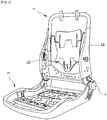
- FIG. 1 is a perspective view mainly illustrating the external shape of a vehicle seat used for a passenger protection apparatus according to Example 1 of the present invention, with an illustration of the airbag apparatus (20) omitted.
- FIG. 2 is a perspective view illustrating an internal structure (seat frame) functioning as the framework of the vehicle seat illustrated in FIG. 1 , with an illustration of the airbag apparatus (20) also omitted here.
- FIG. 3 is a schematic side view of the passenger protection apparatus according to Example 1, in addition to illustrating the state in which the airbag apparatus 20 housed therein on the side face (near side) near the door of the vehicle seat is observed from the outside in the vehicle width direction.
- the present invention is a passenger protection apparatus including: a vehicle seat; and a side airbag apparatus (20) housed in this seat.
- the vehicle seat according to the present example is configured by: a seat cushion 2 of the part on which a passenger is seated; a seat back 1 forming a backrest; and a headrest 3 coupled to the upper end of the seat back 1.
- a seat back frame 1f forming the skeleton of the seat is provided inside the seat back 1, a pad made of a urethane foam material, etc. is provided on the surface and periphery thereof, and the surface of this pad is covered with a skin 14 such as leather or fabric.
- a seating frame 2f is arranged on the bottom side of the seat cushion 2, a pad made of a urethane foam material, etc. is provided on the upper surface and periphery thereof, and this pad surface is covered with the skin 14 ( FIG. 4 ) such as leather or fabric.
- the seating frame 2f and the seat back frame 1f are coupled via a reclining mechanism 4.
- the seat back frame 1f is configured in a frame shape by: a side frame 10 which is arranged so as to be separated into the left and right and extends in the vertical direction; an upper frame coupled to the upper end of this side frame 10; and a lower frame coupled to the lower end thereof.
- a cushion member is provided outside a headrest frame to configure the headrest 3.
- FIG. 4 is a cross sectional view illustrating the structure of the passenger protection apparatus according to the present invention, corresponding to part of the cross section in the A1 -A1 direction of FIG. 3 .
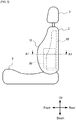
- FIG. 5 is a schematic side view of the passenger protection apparatus according to the present invention and illustrates the state in which the airbag deployed therein is observed from the outside in the vehicle width direction.
- the side frame 10 can be molded of resin or metal and, as illustrated in FIG. 4 , can be formed into an L shaped cross sectional shape or a U shaped cross sectional shape.
- the side frame 10 includes a frame side wall part 10a which extends in the vehicle traveling direction when the horizontal cross section is seen from above.
- an airbag module (side airbag apparatus) 20 is fixed to the outside in the vehicle width direction of this frame side wall part 10a.
- the seat back 1 includes a side support part 12 which swells in the vehicle traveling direction (vehicle front) on the vehicle width direction side (end).
- the side airbag apparatus 20 is housed in a gap with a urethane pad 16 not arranged therein.
- the side airbag apparatus 20 includes: an airbag 34 for restraining a passenger when expanded and deployed; and an inflator 30 for supplying expansion gas to the airbag 34.
- a start region 26 as a starting point (when the side support part 12 bends towards the passenger side due to the expansion of a second chamber (C2)) is formed in the side support part 12.
- the start region 26 can be any one of a notch, recess, or thin region, or combinations thereof.
- the start region 26 only needs to be formed at a urethane 16 part inside the side support part 12. Moreover, the start region 26 can be omitted.
- the airbag 34 is covered with a flexible cover 20a made of fabric.
- the airbag 34 for example, can appropriately employ folding or rolling in bellows ("folding" includes rolling), in addition to an appropriate compression method.
- the symbol 25 denotes a door trim.
- the first chamber (C1) side on which the inflator 30 is housed is disposed outside in the vehicle width direction of the frame side wall part 10a, while the second chamber (C2) coupled to this first chamber (C1) is arranged inside in the vehicle width direction of the frame side wall part 10a.
- the airbag 34 includes: the first chamber C1 which is deployed towards the front of the side support part 12; and the second chamber C2 which is deployed inside in the vehicle width direction of the first chamber C1.
- the second chamber C2 is deformed so as to make at least the front side part 14 of the side support part 12 protrude towards the passenger. Moreover, the second chamber C2 is arranged below the side support part 12 (see FIG. 5 ), while this second chamber C2 is deployed so as to contact and press the side support part 12 with the waist part of the passenger. By pushing the waist part close to the center of gravity of the human body, the restraint performance of a passenger in the initial stage when an accident occurs can be improved.
- the capacity of the second chamber C2 is set to be smaller than the capacity of the first chamber C1.
- the shape and capacity of the second chamber C2 may be adjusted such that the second chamber C2 may only be deployed inside the side support part 12. In other words, the deployed second chamber C2 may not stick out to the vehicle front compared with the front end of the cleft side support part 12.
- the deploying behavior of the first chamber C1 and the second chamber C2 can be adjusted by a method of folding the airbag, the configuration of the folded airbag 34, the setting of the gas jet direction of the inflator 30, the direction of the gas flow between the first chamber C1 and the second chamber C2, etc.
- chambers constituting the airbag are defined as C1 to C6 substantially along the flow of the expansion gas, a portion thereof do not necessarily coincide with the flow of the gas.
- the front chamber part is labeled "F”
- the rear chamber part is labeled "R.”
- the front chamber part is defined as "C2F”
- the rear chamber part is defined as "C2R.”
- An internal vent hole provided between each chamber is represented using the numbers of the chambers coupled thereto, wherein, for example, an internal vent between the first chamber and the second chamber is "V1-2.” Others also follow the same rule.
- a vent hole for discharging gas to the outside is collectively referred to by the symbol "VF" for convenience irrespective of the location within which the vent hole is provided.
- the front end thereof is labeled "f”
- the rear end thereof is labeled "r.”
- the number (2) corresponding to the number (C2, etc.) of the chamber is assigned.
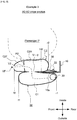
- FIG. 6 is a schematic view illustrating the deployed state of an airbag apparatus according to Example 1 of the present invention, corresponding to the cross section in the A2-A2 direction of FIG. 3 .
- the side airbag apparatus 20 includes: an airbag 34 for restraining a passenger when expanded and deployed; and an inflator 30 for supplying expansion gas to the airbag 34,
- the airbag 34 includes: a first chamber C1 which houses the inflator 30 and is deployed outside in the vehicle width direction of the frame side wall part 10a; and a second chamber C2 which is deployed inside in the vehicle width direction of the frame side wall part 10a.
- the first chamber C1 is deployed such that the rear part thereof, as seen from the vehicle side, overlaps the frame side wall part 10a.
- a rear end part r2 in an expanding region of the second chamber C2 is deployed so as to be disposed in front of a rear end part r1 of the first chamber C1, as seen from the vehicle side.
- the inflator 30 is housed inside the first chamber C1.
- a cylindrical cylinder type inflator can be used.
- a pair of upper and lower stud bolts 32 protrude from the outer peripheral part of the inflator 30 towards the inside in the vehicle width direction. These stud bolts 32 are attached (fastened and fixed) to the side frame 10 by nuts.
- Multiple gas jet ports arranged in the peripheral direction are formed in the inflator 30, with the gas radially ejected from the gas jet port. Note that a diffuser for controlling the flow of the gas can be provided as required.
- An airbag control ECU (not illustrated) mounted on the vehicle is electrically connected to this inflator 30.
- a satellite sensor for detecting side collisions is electrically connected to this airbag control ECU.
- the inflator 30 can be configured to operate when the airbag control ECU detects a side collision based on a signal from this satellite sensor.
- a vent hole V1-2 is formed between the first chamber C1 and the second chamber C2.
- the front end f2 of the second chamber C2 is disposed in front of the front end f1 of the first chamber C1.
- the flow of the expansion gas flows from the first chamber C1 to the second chamber C2 via the vent hole V1-2, and then is discharged from an external vent hole VF formed at the front end of the second chamber C2.
- the first chamber C1 is deployed outside the side support part in the initial stage of operating the airbag apparatus.
- the first chamber C1 is deployed so as to overlap the frame side wall part 10a, as seen from the vehicle side, the first chamber C1 is assuredly deployed such that the frame side wall part 10a receives the reaction force of the first chamber C1.
- the second chamber C2 is deployed so as to quickly restrain a passenger P from moving to the outside in the vehicle width direction.
- the surface on the frame side of the second chamber C2 is supported by both this frame side wall part and the first chamber (which has already started to be deployed), with both the frame side wall part 10a and the first chamber C1 receiving the reaction force when the second chamber is deployed. Therefore, when the passenger P enters the second chamber C2, the pressure from the passenger P can be received by the frame side wall part 10a, making it possible to assuredly restrain the passenger P in the seat center direction.
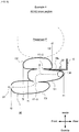
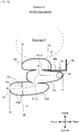
- FIG. 7 is a schematic view illustrating the deployed state of an airbag apparatus according to Example 2 of the present invention, corresponding to the cross section in the A2-A2 direction of FIG. 3 .
- the side airbag apparatus 20 includes: an airbag 34 for restraining a passenger when expanded and deployed; and an inflator 30 for supplying expansion gas to the airbag 34,
- the airbag 34 includes: a first chamber C1 which houses the inflator 30 and is deployed outside in the vehicle width direction of the frame side wall part 10a; and a second chamber C2 which is deployed inside in the vehicle width direction of the frame side wall part 10a.
- the first chamber C1 is deployed such that the rear part thereof, as seen from the vehicle side, overlaps the frame side wall part 10a.
- a rear end part r2 in an expanding region of the second chamber C2 is deployed so as to be disposed in front of a rear end part r1 of the first chamber C1, as seen from the vehicle side.
- the difference between the present example and the abovementioned Example 1 is only a strap (strip member) 36 provided at the rear end of the second chamber C2.
- the strap 36 couples the rear end of the second chamber C2 and the stud bolts 32. Note that the rear end of the strap 36 can be coupled to the side frame 10. In such a configuration, the deploying behavior, deployed shape, and deployed position in the anteroposterior direction of the second chamber C2 can be controlled.
- a non-expanding region can be configured so as to be formed in the rear of the expanding region of the second chamber C2, with this non-expanding region capable of being configured so as to be coupled to the stud bolts 32 for attaching the side frame 10 or the inflator 30 to the side frame 10.
- FIG. 8 is a schematic view illustrating the deployed state of an airbag apparatus according to Example 3 of the present invention, corresponding to the cross section in the A2-A2 direction of FIG. 3 .
- the side airbag apparatus 20 includes: an airbag 34 for restraining a passenger when expanded and deployed; and an inflator 30 for supplying expansion gas to the airbag 34,
- the airbag 34 includes: a first chamber C1 which houses the inflator 30 and is deployed outside in the vehicle width direction of the frame side wall part 10a; and a second chamber C2 which is deployed inside in the vehicle width direction of the frame side wall part 10a.
- the first chamber C1 is deployed such that the rear part thereof, as seen from the vehicle side, overlaps the frame side wall part 10a.
- a rear end part r2 in an expanding region of the second chamber C2 is deployed so as to be disposed in front of a rear end part r1 of the first chamber C1, as seen from the vehicle side.
- the present example is a modified example of the abovementioned Example 2, wherein the difference is that the second chamber C2 is sectioned into the front and rear so as to form a front chamber part C2F and a rear chamber part C2R.
- a partition panel P2 is arranged at the boundary part between the front chamber part C2F and the rear chamber part C2R, with a vent hole V2 formed at a portion thereof.
- the width in the anteroposterior direction of the second chamber C2 is easily enlarged.
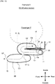
- FIG. 9 is a schematic view illustrating the deployed state of an airbag apparatus according to Example 4 of the present invention, corresponding to the cross section in the A2-A2 direction of FIG. 3 .
- the side airbag apparatus 20 includes: an airbag 34 for restraining a passenger when expanded and deployed; and an inflator 30 for supplying expansion gas to the airbag 34,
- the airbag 34 includes: a first chamber C1 which houses the inflator 30 and is deployed outside in the vehicle width direction of the frame side wall part 10a; and a second chamber C2 which is deployed inside in the vehicle width direction of the frame side wall part 10a.
- the first chamber C1 is deployed such that the rear part thereof, as seen from the vehicle side, overlaps the frame side wall part 10a.
- a rear end part r2 in an expanding region of the second chamber C2 is deployed so as to be disposed in front of a rear end part r1 of the first chamber C1, as seen from the vehicle side.
- a third chamber C3 coupled to this first chamber C1 is included on the side of the first chamber C1 opposite to (outside) the second chamber C2.
- An internal vent hole V1-3 is formed at the boundary part between the first chamber C1 and the third chamber C3 such that the gas inside the first chamber C1 flows into the third chamber C3. Therefore, the expansion gas branched from the first chamber C1 is separately fed into the second chamber C2 and the third chamber C3, respectively, thereby contributing to the quick deployment of the second chamber C2 and the third chamber C3.
- the front end part of the third chamber C3 is disposed in front of the front end parts of the first chamber C1 and the second chamber C2, when seen as the deployed shape of the overall airbag, the width in the anteroposterior direction can be relatively easily increased.
- FIG. 10 is a schematic view illustrating the deployed state of an airbag apparatus according to Example 5 of the present invention, corresponding to the cross section in the A2-A2 direction of FIG. 3 .
- the side airbag apparatus 20 includes: an airbag 34 for restraining a passenger when expanded and deployed; and an inflator 30 for supplying expansion gas to the airbag 34,
- the airbag 34 includes: a first chamber C1 which houses the inflator 30 and is deployed outside in the vehicle width direction of the frame side wall part 10a; and a second chamber C2 which is deployed inside in the vehicle width direction of the frame side wall part 10a.
- the first chamber C1 is deployed such that the rear part thereof, as seen from the vehicle side, overlaps the frame side wall part 10a.
- a rear end part r2 in an expanding region of the second chamber C2 is deployed so as to be disposed in front of a rear end part r1 of the first chamber C1, as seen from the vehicle side.
- the present example is a modified example of the abovementioned Example 4, with most configurations identical.
- the difference is that a partition panel P6 sections the third chamber C3 into a front chamber part C3F and a rear chamber part C3R, with a vent hole V3 provided at this partition panel P6.
- the width in the anteroposterior direction of the third chamber C3 is easily enlarged.
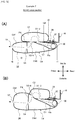
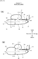
- FIGS. 11(A), (B) are schematic views illustrating the deployed state of an airbag apparatus according to Example 6 of the present invention, corresponding to the cross section in the A2-A2 direction of FIG. 3 .
- the examples illustrated in both figures (A) and (B) are configured based on the same concept, only differing in terms of the configuration and structure of a fourth chamber C4.
- the side airbag apparatus 20 includes: an airbag 34 for restraining a passenger when expanded and deployed; and an inflator 30 for supplying expansion gas to the airbag 34,
- the airbag 34 includes: a first chamber C1 which houses the inflator 30 and is deployed outside in the vehicle width direction of the frame side wall part 10a; and a second chamber C2 which is deployed inside in the vehicle width direction of the frame side wall part 10a.
- the first chamber C1 is deployed such that the rear part thereof, as seen from the vehicle side, overlaps the frame side wall part 10a.
- a rear end part r2 in an expanding region of the second chamber C2 is deployed so as to be disposed in front of a rear end part r1 of the first chamber C1 and hardly overlap the frame side wall part 10a as seen from the vehicle side.
- the fourth chamber C4 coupled to the front end of the first chamber C1 and the side face of the second chamber C2 is further included.
- an internal vent hole V2-4 is formed at the boundary part between the second chamber C2 and the fourth chamber C4 such that the gas inside the second chamber C2 flows into the fourth chamber C4. Note that the first chamber C1 and the fourth chambers C4 are completely separated.
- the fourth chamber C4 is disposed outside the side frame 10, so as to be deployed in front of the first chamber C1 and outside the second chamber C2.
- the fourth chamber C4 is deployed in front of the first chamber and in front of the side frame 10, in addition to being partially disposed in front of the second chamber C2.
- the structure as in figure (B) advantageously allows the flow of gas to smoothly reach the fourth chamber C4 from the first chamber C1 via the second chamber C2.
- the expansion gas flows in the order of the first chamber C1, the second chamber C2, and the fourth chamber C4, and is expanded and deployed in this order. Therefore, the passenger P is quickly restrained by the first chamber C1 and the second chamber C2 in an early stage, allowing the restraint range to be widely assured by the fourth chamber C4.
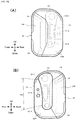
- FIGS. 12(A), (B) are schematic views illustrating the deployed state of an airbag apparatus according to Example 7 of the present invention, corresponding to the cross section in the A2-A2 direction of FIG. 3 .
- the examples illustrated in both figures (A) and (B) are configured based on the same concept, only differing in terms of the configuration and structure of a fourth chamber C4.
- the side airbag apparatus 20 includes: an airbag 34 for restraining a passenger when expanded and deployed; and an inflator 30 for supplying expansion gas to the airbag 34,
- the airbag 34 includes: a first chamber C1 which houses the inflator 30 and is deployed outside in the vehicle width direction of the frame side wall part 10a; and a second chamber C2 which is deployed inside in the vehicle width direction of the frame side wall part 10a.
- the first chamber C1 is deployed such that the rear part thereof, as seen from the vehicle side, overlaps the frame side wall part 10a.
- the second chamber C2 is deployed such that, as seen from the vehicle side, the front part does not overlap the first chamber C1, while the rear part thereof overlaps the frame side wall part 10a.
- the greatest characteristic of the side airbag apparatus according to the present example is the further inclusion of the fourth chamber C4 housing the first chamber C1 outside the frame side wall part 10a.
- the presence of the fourth chamber C4 allows the capacity of the first chamber C1 to be relatively small, while the gas emitted from the inflator 30 is more likely to be introduced in the desired direction, resulting in improved rectification effects of the gas.
- the fourth chamber C4 is sectioned into a front chamber part C4F and a rear chamber part C4R, with the internal vent hole V4 provided at this section part.
- the vent hole V1-2 is formed at the boundary part between the first chamber C1 and the second chamber C2
- the vent hole V2-4 is formed at the boundary part between the second chamber C2 and the rear chamber part C4R the fourth chamber C4.
- the gas emitted from the inflator flows in the order of the first chamber C1, the second chamber C2, the rear chamber part C4R of the fourth chamber C4, and the front chamber part C4F of the fourth chamber C4.
- the fourth chamber C4 (C4F, C4R) is disposed outside the side frame 10, so as to be deployed in front of the first chamber C1 and outside the second chamber C2.
- the fourth chamber C4 (specifically, C4F) is deployed in front of the first chamber and in front of the side frame 10, in addition to being partially disposed in front of the second chamber C2.
- the structure as in figure (B) advantageously allows the flow of gas to smoothly reach the fourth chamber C4 from the first chamber C1 via the second chamber C2.
- FIG. 13 is a schematic view illustrating the deployed state of an airbag apparatus according to Example 8 of the present invention, corresponding to the cross section in the A2-A2 direction of FIG. 3 .
- the side airbag apparatus 20 includes: an airbag 34 for restraining a passenger when expanded and deployed; and an inflator 30 for supplying expansion gas to the airbag 34,
- the airbag 34 includes: a first chamber C1 which houses the inflator 30 and is deployed outside in the vehicle width direction of the frame side wall part 10a; and a second chamber C2 which is deployed inside in the vehicle width direction of the frame side wall part 10a.
- the first chamber C1 is deployed such that the rear part thereof, as seen from the vehicle side, overlaps the frame side wall part 10a.
- the second chamber C2 is deployed so as not to overlap the rear part of the first chamber C1, as seen from the vehicle side.
- the greatest characteristic of the present example is the fact that the first chamber C1 and the second chamber C2 are configured as one chamber. A single chamber is folded so as to hold the frame side wall part 10a. According to the present example, the number of panels constituting the airbag 34 can be decreased to simplify the overall panel structure.
- the airbag 34 further includes the third chamber C3 coupled to the outside of the first chamber C1, with the internal vent hole V1-3 provided between the first chamber C1 and the third chamber C3.
- the gas emitted from the inflator 30 passes inside the first chamber C1 so as to be branched into the second chamber C2 side and the third chamber C3 side in the vicinity of the front end of the frame side wall part 10a.
- FIG. 14 is a schematic view illustrating the deployed state of an airbag apparatus according to Example 9 of the present invention, corresponding to the cross section in the A2-A2 direction of FIG. 3 .
- the side airbag apparatus 20 includes: an airbag 34 for restraining a passenger when expanded and deployed; and an inflator 30 for supplying expansion gas to the airbag 34,
- the airbag 34 includes: a first chamber C1 which houses the inflator 30 and is deployed outside in the vehicle width direction of the frame side wall part 10a; and a second chamber C2 which is deployed inside in the vehicle width direction of the frame side wall part 10a.
- the first chamber C1 is deployed such that the rear part thereof, as seen from the vehicle side, overlaps the frame side wall part 10a.
- the second chamber C2 is deployed so as not to overlap the rear part of the first chamber C1, as seen from the vehicle side.
- the present example is a modified example of the abovementioned Example 8, with most configurations identical.
- the difference is that the third chamber C3 is sectioned into a front chamber part C3F and a rear chamber part C3R, with the internal vent hole V3 provided at this section part.
- FIGS. 15(A), (B) are schematic views illustrating the deployed state of an airbag apparatus according to Example 10 of the present invention, corresponding to the cross section in the A2-A2 direction of FIG. 3 .
- the examples illustrated in both figures (A) and (B) are configured based on the same concept, only differing in terms of the configuration and structure of a fourth chamber C4.
- FIG. 16 is a side view illustrating the deployed state of the airbag apparatus illustrated in FIG. 15 , in addition to illustrating the configuration and shape of panels constituting the airbag.
- the side airbag apparatus 20 includes: an airbag 34 for restraining a passenger when expanded and deployed; and an inflator 30 for supplying expansion gas to the airbag 34,
- the airbag 34 includes: a first chamber C1 which houses the inflator 30 and is deployed outside in the vehicle width direction of the frame side wall part 10a; and a second chamber C2 which is deployed inside in the vehicle width direction of the frame side wall part 10a.
- the first chamber C1 is deployed such that the rear part thereof, as seen from the vehicle side, overlaps the frame side wall part 10a.
- the rear end part r2 in the expanding region of the second chamber C2 is disposed slightly in front of the rear end part r1 of the first chamber C1, but extends substantially rearward towards the position of the stud bolts 32.
- the present example is a modified example of the abovementioned Example 9, with most configurations identical. The difference is that a protruding expanding part C2P is formed in the rear of the second chamber C2. Note that, needless to say, the protruding expanding part C2P of the second chamber C2 employed in the present example can also be applied to the abovementioned Examples 1 to 9.
- the protruding expanding part C2P is divided into a part C2PU disposed above two holes 32U, 32L for the stud bolts 32, along with a part C2PL disposed therebelow.
- protruding expanding parts C2PU, C2PL are formed in order to avoid the position of each hole 32U, 32L for the stud bolt 32, that is, the attachment position of the inflator 30, protruding expanding parts C2PU, C2PL are formed.
- a non-expanding region 136 is disposed between these two protruding expanding parts C2PU, C2PL, with this non-expanding region 136 fastened and fixed to the stud bolts 32.
- non-expanding region 136 functions in the same way as the strap 36 in the abovementioned other examples. That is, by coupling and fixing the non-expanding region 136 to the stud bolts 32, the deploying behavior, deployed shape, and deployed position in the anteroposterior direction of the second chamber C2 can be controlled.
- the fourth chamber C4 (C4F, C4R) is disposed outside the side frame 10, so as to be deployed in front of the first chamber C1 and outside the second chamber C2.
- the fourth chamber C4 (specifically, C4F) is deployed in front of the first chamber and in front of the side frame 10, in addition to being partially disposed in front of the second chamber C2.
- the structure as in figure (B) advantageously allows the flow of gas to smoothly reach the fourth chamber C4 from the first chamber C1 via the second chamber C2.
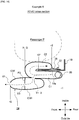
- FIG. 17 is a schematic view illustrating the deployed state of an airbag apparatus according to Example 11 of the present invention, corresponding to the cross section in the A2-A2 direction of FIG. 3 .
- the examples illustrated in both figures (A) and (B) are configured based on the same concept, only differing in terms of the configuration and structure of a fourth chamber C4. Note that because the present example has a large number of parts common to Example 6 illustrated in FIG. 11 , descriptions will be provided focusing on the differences from Example 6 in order to facilitate understanding.
- vent hole V1-4 is formed at the boundary part between the fourth chamber C4 and the first chamber C1 such that the gas inside the first chamber C1 flows into the fourth chamber C4.
- a vent hole V2-4 present at the boundary part between the second chamber C2 and the fourth chamber C4 is not provided in the present example.
- the expansion gas is configured to flow from the first chamber C1 to the second chamber C2 and the fourth chamber C4, the second chamber C2 and the fourth chamber C4 are substantially simultaneously expanded and deployed. Therefore, advantageously, the passenger can be substantially simultaneously protected by the fourth chamber (main chamber) C4 and the second chamber (pre-push chamber) C2. For example, even in a state in which the passenger P sits slightly on the tip side of a seating face of a seat and cannot be sufficiently restrained by the second chamber C2, the fourth chamber C4 enables the passenger P4 to be quickly and assuredly restrained in the initial stage of the collision.
- the fourth chamber C4 (C4F, C4R) is disposed outside the frame side wall part 10a of the side frame 10, so as to be deployed in front of the first chamber C1 and outside the second chamber C2.
- the fourth chamber C4 (specifically, C4F) is deployed in front of the first chamber and in front of the frame side wall part 10a of the side frame 10, in addition to being partially disposed in front of the second chamber C2.
- FIG. 18 is a schematic view illustrating the deployed state of an airbag apparatus according to Example 12 of the present invention, corresponding to the cross section in the A2-A2 direction of FIG. 3 .
- the examples illustrated in both figures (A) and (B) are configured based on the same concept, only differing in terms of the configuration and structure of a fourth chamber C4.
- FIG. 19 is a side view illustrating the deployed state of the airbag apparatus illustrated in FIG. 18 , in addition to illustrating the configuration and shape of panels constituting the airbag. Note that because the present example has a large number of parts common to Example 10 illustrated in FIG. 15 , descriptions will be provided focusing on the differences from Example 10 in order to facilitate understanding.
- the second chamber C2 when the airbag in the deployed state is observed from the vehicle width direction, the second chamber C2 is configured so as not to overlap the frame side wall part 10a of the side frame 10.
- a front wall part 210 which protrudes towards the inside (inside in the vehicle width direction) of the vehicle is formed at the front end of the frame side wall part 10a and supported such that the rear end part of the second chamber C2 abuts this front wall part 210.
- the first chamber C1 is provided so as to surround the inflator 30 in the so-called bag-in bag-out form.
- the specific range 200 at the rear edge part of the second chamber C2 is molded so as to be curved along a smoothly swelled front edge shape of a side wall part 10a of the side frame 10.
- Such a structure enables the second chamber C2 to be closely adhered to the front edge of the side wall part 10a, allows the reaction force to be obtained in this closely adhered region, stabilizes the deployed shape of the second chamber C2, and further enables quick and assured forward deployment.
- the fourth chamber C4 (C4F, C4R) is disposed outside the side frame 10 so as to be deployed in front of the first chamber C1 and outside the second chamber C2.
- the fourth chamber C4 (specifically, C4F) is deployed in front of the first chamber and in front of the side frame 10, in addition to being partially disposed in front of the second chamber C2.
- the structure as in figure (B) advantageously allows the flow of gas to smoothly reach the fourth chamber C4 from the first chamber C1 via the second chamber C2.
- a side airbag apparatus on the near side has been predominantly mentioned in the Description of the Preferred Embodiment
- a far side airbag apparatus surface on the far side from a vehicle door of a vehicle seat
- very small vehicles such as a single seat vehicle (irrespective of the presence of a door, a vehicle including parts with only one seat in a single row), and the like.
Description
- The present invention relates to a passenger protection apparatus including a side airbag apparatus which protects passengers when deployed on the seat side of a vehicle.
- In order to protect passengers when a vehicle accident occurs, it is well known that vehicles are equipped with one or more airbags. These airbags, for example, include various forms such as: a so-called driver airbag which is expanded from the vicinity of the steering wheel of an automobile so as protect the driver; a curtain airbag which is deployed downward inside the window of an automobile so as to protect passengers during collisions in the transverse direction of a vehicle, overturning, and rollover accidents; and a side airbag apparatus which is deployed on the side (seat side) of passengers so as to protect the passenger upon impact in the transverse direction of a vehicle. The present invention relates to a side airbag apparatus provided in a vehicle seat.
- The side airbag apparatus described in the below mentioned
Patent Document 1 includes a main airbag along with an auxiliary airbag. In addition, prior to the main airbag, the auxiliary airbag is expanded and deployed to restrain passengers at an early stage. In addition to the invention described inPatent Document 1, a side airbag apparatus including the auxiliary airbag as well as the main airbag is proposed. With such a side airbag apparatus, there is great restraint in the installation region, resulting in a strong demand for size reduction of the apparatus.EP3050761 A shows a passenger protection apparatus according to the preamble ofclaim 1. - Moreover, there is a demand for appropriate passenger protection performance due to improved deployment speed and stabilization of the deployed shape.
- [Patent Document 1]
JP 2009-023494 A - The present invention has been created in view of the abovementioned problem, with an object of providing a passenger protection apparatus which includes a side airbag apparatus capable of quickly and properly restraining a passenger.
Moreover, another object is to provide a passenger protection apparatus including a side airbag apparatus which contributes to the size reduction of the apparatus. - In order to achieve the abovementioned objects, the present invention, as in
claim 1, is applied to a passenger protection apparatus, including: a vehicle seat having a seat cushion forming a seating face along with a seat back forming a backrest; and a side airbag apparatus housed in this seat.
Here, the seat back includes a side support part which swells in the vehicle traveling direction (vehicle front) on the vehicle width direction side (end).
A side frame part having a frame side wall part (which extends in the vehicle traveling direction when the horizontal cross section is seen from above) is arranged inside the side support part.
The side airbag apparatus includes: an airbag which restrains a passenger when expanded and deployed; and an inflator supplying expansion gas to the airbag,
The airbag includes: a first chamber which houses the inflator and is deployed outside in the vehicle width direction of the frame side wall part; and a second chamber which is deployed inside in the vehicle width direction of the frame side wall part.
In addition, the first chamber is deployed such that at least a portion thereof, as seen from the vehicle side, overlaps the frame side wall part. At this time, the rear end part of an expanding region of the second chamber, as seen from the vehicle side, is formed in front of the rear end part of the first chamber. - Note that the inside in the vehicle width direction of the frame side wall part denotes the center side (passenger side) of the seat, while the outside in the vehicle width direction of the frame side wall part denotes the outside (door side, center console side) in the transverse direction of the seat.
- According to the present invention having the abovementioned configuration, the first chamber C1 is deployed outside the side support part in the initial stage of operating the airbag apparatus. At this time, because the first chamber is deployed so as to overlap the frame side wall part, as seen from the vehicle side, the first chamber is assuredly deployed such that the frame side wall part receives the reaction force of the first chamber. Subsequently, the second chamber is deployed so as to quickly restrain a passenger from moving to the outside in the vehicle width direction. At this time, the surface on the frame side of the second chamber is supported by both this frame side wall part and the first chamber (which has already started to be deployed) or only by the first chamber, with both the frame side wall part and the first chamber, or just the first chamber, receiving the reaction force when the second chamber is deployed. Therefore, when the passenger enters the second chamber, the pressure from the passenger can be received by the frame side wall part, making it possible to assuredly restrain the passenger in the seat center direction.
- The first chamber and the second chamber can be provided so as to hold the frame side wall part.
Such a configuration allows the first chamber to be assuredly deployed outside in the vehicle width direction of the frame side wall part, in addition to allowing the second chamber to be assuredly deployed inside in the vehicle width direction of the frame side wall part, thereby easily controlling the deployed position of each chamber. - The second chamber can be deployed, as seen from the vehicle side, so as not to overlap the frame side wall part.
In this case, because the deployed position of the second chamber is shifted forward compared with the case of overlapping the frame side wall part, the shape of the overall airbag is advantageously more likely to be widened forward. - At least one first internal vent hole is preferably formed at the boundary part between the first chamber and the second chamber such that the gas inside the first chamber flows into the second chamber.
The presence of the first internal vent hole allows the expansion gas to be quickly filled into the overall airbag. - The first chamber and the second chamber can be configured as a single chamber.
In this case, the number of panels constituting the airbag can be decreased to simplify the overall panel structure. - The second chamber can be sectioned into a front chamber part and a rear chamber part, wherein at least one second internal vent hole can be provided in this section part.
- The front end part of the second chamber can be disposed in front of the front end part of the first chamber.
In this way, when the front end of the second chamber on the side near the passenger moves forward, for example, a passenger who is seated while bent forward can be restrained, enabling the restraint range of the passenger to be widened. - The passenger protection apparatus can further include a third chamber coupled to this first chamber on the side of the first chamber opposite the second chamber.
By employing such a configuration, compared with the case in which a wide range is protected with a single chamber, the deploying behavior of the airbag is more likely to be perceived, enabling the deployed shape and deployed position of the airbag to be accurately controlled. - Here, at least one third internal vent hole can be formed at the boundary part between the first chamber and the third chamber such that the gas inside the first chamber flows into the third chamber.
In this case, the expansion gas branched from the first chamber is separately fed into the second chamber and the third chamber, respectively, thereby contributing to the quick deployment of the second chamber and the third chamber. - Moreover, the front end part of the third chamber can be configured so as to be disposed in front of the front end parts of the first chamber and the second chamber.
In this case, when seen as the deployed shape of the overall airbag, the width in the anteroposterior direction can be relatively easily increased. - Further, the third chamber can be sectioned into a front chamber part and a rear chamber part, wherein at least one fourth internal vent hole can be provided in this section part. As a result, the width in the anteroposterior direction can be further increased.
- The passenger protection apparatus can further include a fourth chamber coupled to the side face of the second chamber in front of the first chamber.
In addition, at least one fifth internal vent hole can be formed at the boundary part between the second chamber and the fourth chamber such that the gas inside the second chamber flows into the fourth chamber.
By employing such a configuration, because the expansion gas flows in the order of the first chamber, the second chamber, and the fourth chamber, and is expanded and deployed in this order, the passenger can be quickly restrained by the first and second chambers in an early stage, allowing the restraint range to be widely assured by the fourth chamber. - Alternatively, at least one sixth vent hole can be formed at the boundary part between the fourth chamber and the first chamber such that the gas inside the first chamber flows into the fourth chamber.
- Moreover, the rear part of the fourth chamber can be provided outside the side frame so as to cover the outside in the vehicle width direction of the second chamber, such that the first chamber can function as a gas guide to the second chamber.
- The rear part of the fourth chamber can be provided outside the side frame so as to cover the outside in the vehicle width direction of the first chamber, while the first chamber can be provided as a gas guide to the second chamber.
- The passenger protection apparatus further includes a fourth chamber coupled to the outside in the vehicle width direction of the side face of the second chamber, wherein the first chamber can be provided inside the fourth chamber in a bag-in bag-out form.
Here, the fourth chamber can be provided so as to be disposed on the front side of the side frame part. Moreover, at least one fifth internal vent hole is preferably formed at the boundary part between the second chamber and the fourth chamber such that the gas inside the second chamber flows into the fourth chamber. - The front end part of the fourth chamber can be configured so as to be disposed in front of the front end part of the second chamber. Here, the fourth chamber can be configured so as to be coupled to the front end of the first chamber and the side face of the second chamber.
- A protruding expanding part which protrudes rearward so as to be expanded and deployed can be formed in a portion of the second chamber. Here, the protruding expanding part of the second chamber is preferably formed in a configuration so as not to overlap the inflator, as seen from the side.
Normally, the rear part of the second chamber overlaps the space for attaching the inflator, necessitating that the rear end of the second chamber be arranged in front of the inflator. However, by forming the abovementioned protruding expanding part, the second chamber can be extended more rearward than the inflator (stud bolt). As a result, the second chamber can be sufficiently overlapped with the side frame, while the reaction force from the side frame can be utilized when the air bag is expanded and deployed, enabling deployment with a stable behavior and position. - In each chamber constituting the airbag, an external vent hole for discharging the expansion gas to the outside can be provided at the tip of the frontmost chamber.
- The passenger protection apparatus further includes a strap having the front end coupled to the rear side of the second chamber, wherein the rear end of the strap can be configured so as to be coupled to a stud bolt for attaching the side frame or the inflator to the side frame. Alternatively, while a non-expanding region can be configured so as to be formed in the rear of the expanding region of the second chamber, this non-expanding region can be configured so as to be coupled to the stud bolt for attaching the side frame or the inflator to the side frame.
In this case, the deploying behavior, deployed shape, and deployed position in the anteroposterior direction of the second chamber can be controlled. - The side airbag apparatus according to the present invention includes a type which is deployed on the door side of (outside) the seat, along with a type which is deployed on the vehicle center side of the seat. Note that a side airbag apparatus of a type which is deployed on the vehicle center side of the seat, for example, is referred to as a far side airbag apparatus, front center airbag, rear center airbag, etc.
-
-
FIG. 1 is a perspective view mainly illustrating the external shape of a vehicle seat used for a passenger protection apparatus according to the present invention, with an illustration of the airbag unit omitted. -
FIG. 2 is a perspective view illustrating an internal structure (seat frame) functioning as the framework of the vehicle seat illustrated inFIG. 1 , with an illustration of the airbag unit omitted. -
FIG. 3 is a schematic side view of the passenger protection apparatus according to the present invention and illustrates the state in which the airbag unit housed therein is observed from the outside in the vehicle width direction. -
FIG. 4 is a cross sectional view illustrating the structure of the passenger protection apparatus according to the present invention, corresponding to part of the cross section in the A1-A1 direction ofFIG. 3 . -
FIG. 5 is a schematic side view of the passenger protection apparatus according to the present invention and illustrates the state in which the airbag deployed therein is observed from the outside in the vehicle width direction. -
FIG. 6 is a schematic view illustrating the deployed state of an airbag apparatus according to Example 1 of the present invention, corresponding to the cross section in the A2-A2 direction ofFIG. 3 . -
FIG. 7 is a schematic view illustrating the deployed state of an airbag apparatus according to Example 2 of the present invention, corresponding to the cross section in the A2-A2 direction ofFIG. 3 . -
FIG. 8 is a schematic view illustrating the deployed state of an airbag apparatus according to Example 3 of the present invention, corresponding to the cross section in the A2-A2 direction ofFIG. 3 . -
FIG. 9 is a schematic view illustrating the deployed state of an airbag apparatus according to Example 4 of the present invention, corresponding to the cross section in the A2-A2 direction ofFIG. 3 . -
FIG. 10 is a schematic view illustrating the deployed state of an airbag apparatus according to Example 5 of the present invention, corresponding to the cross section in the A2-A2 direction ofFIG. 3 . -
FIGS. 11(A), (B) are schematic views illustrating the deployed state of an airbag apparatus according to Example 6 of the present invention, corresponding to the cross section in the A2-A2 direction ofFIG. 3 . -
FIGS. 12(A), (B) are schematic views illustrating the deployed state of an airbag apparatus according to Example 7 of the present invention, corresponding to the cross section in the A2-A2 direction ofFIG. 3 . -
FIG. 13 is a schematic view illustrating the deployed state of an airbag apparatus according to Example 8 of the present invention, corresponding to the cross section in the A2-A2 direction ofFIG. 3 . -
FIG. 14 is a schematic view illustrating the deployed state of an airbag apparatus according to Example 9 of the present invention, corresponding to the cross section in the A2-A2 direction ofFIG. 3 . -
FIGS. 15(A), (B) are schematic views illustrating the deployed state of an airbag apparatus according to Example 10 of the present invention, corresponding to the cross section in the A2-A2 direction ofFIG. 3 . -
FIG. 16 is a side view illustrating the deployed state of the airbag apparatus illustrated inFIG. 15 , in addition to illustrating the configuration and shape of panels constituting the airbag. -
FIGS. 17(A), (B) are schematic views illustrating the deployed state of an airbag apparatus according to Example 11 of the present invention, corresponding to the cross section in the A2-A2 direction ofFIG. 3 . -
FIGS. 18(A), (B) are schematic views illustrating the deployed state of an airbag apparatus according to Example 12 of the present invention, corresponding to the cross section in the A2-A2 direction ofFIG. 3 . -
FIG. 19 is a side view illustrating the deployed state of the airbag apparatus illustrated inFIG. 18 , in addition to illustrating the configuration and shape of panels constituting the airbag. - A vehicle seat with a side airbag apparatus according to embodiments of the present invention mounted thereon will be described with reference to the accompanying drawings. Note that "front" displayed in each figure denotes the front (traveling direction) of a vehicle, "rear" denotes the rear (on the side opposite the traveling direction) of the vehicle, "inside" denotes the inside in the vehicle width direction (on the passenger side), and "outside" denotes the outside in the vehicle width direction (on the door panel side).
-
FIG. 1 is a perspective view mainly illustrating the external shape of a vehicle seat used for a passenger protection apparatus according to Example 1 of the present invention, with an illustration of the airbag apparatus (20) omitted.FIG. 2 is a perspective view illustrating an internal structure (seat frame) functioning as the framework of the vehicle seat illustrated inFIG. 1 , with an illustration of the airbag apparatus (20) also omitted here.FIG. 3 is a schematic side view of the passenger protection apparatus according to Example 1, in addition to illustrating the state in which theairbag apparatus 20 housed therein on the side face (near side) near the door of the vehicle seat is observed from the outside in the vehicle width direction. - The present invention is a passenger protection apparatus including: a vehicle seat; and a side airbag apparatus (20) housed in this seat. As illustrated in
FIGS. 1 and2 , seen as the location, the vehicle seat according to the present example is configured by: aseat cushion 2 of the part on which a passenger is seated; a seat back 1 forming a backrest; and aheadrest 3 coupled to the upper end of the seat back 1. - A seat back
frame 1f forming the skeleton of the seat is provided inside the seat back 1, a pad made of a urethane foam material, etc. is provided on the surface and periphery thereof, and the surface of this pad is covered with askin 14 such as leather or fabric. Aseating frame 2f is arranged on the bottom side of theseat cushion 2, a pad made of a urethane foam material, etc. is provided on the upper surface and periphery thereof, and this pad surface is covered with the skin 14 (FIG. 4 ) such as leather or fabric. Theseating frame 2f and the seat backframe 1f are coupled via areclining mechanism 4. - As illustrated in
FIG. 2 , the seat backframe 1f is configured in a frame shape by: aside frame 10 which is arranged so as to be separated into the left and right and extends in the vertical direction; an upper frame coupled to the upper end of thisside frame 10; and a lower frame coupled to the lower end thereof. A cushion member is provided outside a headrest frame to configure theheadrest 3. -
FIG. 4 is a cross sectional view illustrating the structure of the passenger protection apparatus according to the present invention, corresponding to part of the cross section in the A1 -A1 direction ofFIG. 3 .FIG. 5 is a schematic side view of the passenger protection apparatus according to the present invention and illustrates the state in which the airbag deployed therein is observed from the outside in the vehicle width direction. - The
side frame 10 can be molded of resin or metal and, as illustrated inFIG. 4 , can be formed into an L shaped cross sectional shape or a U shaped cross sectional shape. Theside frame 10 includes a frameside wall part 10a which extends in the vehicle traveling direction when the horizontal cross section is seen from above. In addition, an airbag module (side airbag apparatus) 20 is fixed to the outside in the vehicle width direction of this frameside wall part 10a. - As illustrated in
FIG. 4 , the seat back 1 includes aside support part 12 which swells in the vehicle traveling direction (vehicle front) on the vehicle width direction side (end). Inside theside support part 12, theside airbag apparatus 20 is housed in a gap with aurethane pad 16 not arranged therein. Theside airbag apparatus 20 includes: anairbag 34 for restraining a passenger when expanded and deployed; and an inflator 30 for supplying expansion gas to theairbag 34. -
Seams skin 14 of the seat back 1 are interwoven and coupled by sewing. Note that thefront seam 18 is cleft when the airbag is deployed.
Moreover, astart region 26 as a starting point (when theside support part 12 bends towards the passenger side due to the expansion of a second chamber (C2)) is formed in theside support part 12. Thestart region 26 can be any one of a notch, recess, or thin region, or combinations thereof. Thestart region 26 only needs to be formed at aurethane 16 part inside theside support part 12. Moreover, thestart region 26 can be omitted. - The
airbag 34 is covered with aflexible cover 20a made of fabric. Theairbag 34, for example, can appropriately employ folding or rolling in bellows ("folding" includes rolling), in addition to an appropriate compression method. InFIG. 4 , thesymbol 25 denotes a door trim. As will be described later in detail, in the storage state in which theairbag 34 is folded, in order to maintain the positional relationship when the airbag is expanded and deployed, the first chamber (C1) side on which theinflator 30 is housed is disposed outside in the vehicle width direction of the frameside wall part 10a, while the second chamber (C2) coupled to this first chamber (C1) is arranged inside in the vehicle width direction of the frameside wall part 10a. - As illustrated in
FIG. 5 , theairbag 34 includes: the first chamber C1 which is deployed towards the front of theside support part 12; and the second chamber C2 which is deployed inside in the vehicle width direction of the first chamber C1. - The second chamber C2 is deformed so as to make at least the
front side part 14 of theside support part 12 protrude towards the passenger. Moreover, the second chamber C2 is arranged below the side support part 12 (seeFIG. 5 ), while this second chamber C2 is deployed so as to contact and press theside support part 12 with the waist part of the passenger. By pushing the waist part close to the center of gravity of the human body, the restraint performance of a passenger in the initial stage when an accident occurs can be improved. The capacity of the second chamber C2 is set to be smaller than the capacity of the first chamber C1. - Note that the shape and capacity of the second chamber C2 may be adjusted such that the second chamber C2 may only be deployed inside the
side support part 12. In other words, the deployed second chamber C2 may not stick out to the vehicle front compared with the front end of the cleftside support part 12. Moreover, the deploying behavior of the first chamber C1 and the second chamber C2 can be adjusted by a method of folding the airbag, the configuration of the foldedairbag 34, the setting of the gas jet direction of the inflator 30, the direction of the gas flow between the first chamber C1 and the second chamber C2, etc. - While examples according to the present invention will hereinafter be described, reference symbols are provided based on a predetermined rule in the accompanying drawings for convenience and will be initially described regarding this point.
While chambers constituting the airbag are defined as C1 to C6 substantially along the flow of the expansion gas, a portion thereof do not necessarily coincide with the flow of the gas. Moreover, if one chamber is divided into the front and rear, the front chamber part is labeled "F," while the rear chamber part is labeled "R." For example, if the second chamber C2 is divided into the two parts of the front and rear, the front chamber part is defined as "C2F," while the rear chamber part is defined as "C2R." - An internal vent hole provided between each chamber is represented using the numbers of the chambers coupled thereto, wherein, for example, an internal vent between the first chamber and the second chamber is "V1-2." Others also follow the same rule. A vent hole for discharging gas to the outside is collectively referred to by the symbol "VF" for convenience irrespective of the location within which the vent hole is provided.
Regarding the position of the end of chambers in the anteroposterior direction along the vehicle traveling direction, the front end thereof is labeled "f," while the rear end thereof is labeled "r." In addition, after f, r, the number (2) corresponding to the number (C2, etc.) of the chamber is assigned. - Note that in each example, while identical components are labeled with identical symbols, not identical but similar components may be labeled with identical symbols.
-
FIG. 6 is a schematic view illustrating the deployed state of an airbag apparatus according to Example 1 of the present invention, corresponding to the cross section in the A2-A2 direction ofFIG. 3 . Theside airbag apparatus 20 according to the present example includes: anairbag 34 for restraining a passenger when expanded and deployed; and an inflator 30 for supplying expansion gas to theairbag 34, Theairbag 34 includes: a first chamber C1 which houses the inflator 30 and is deployed outside in the vehicle width direction of the frameside wall part 10a; and a second chamber C2 which is deployed inside in the vehicle width direction of the frameside wall part 10a. In addition, the first chamber C1 is deployed such that the rear part thereof, as seen from the vehicle side, overlaps the frameside wall part 10a. In contrast, a rear end part r2 in an expanding region of the second chamber C2 is deployed so as to be disposed in front of a rear end part r1 of the first chamber C1, as seen from the vehicle side. - As illustrated in
FIG. 6 , in the present example, theinflator 30 is housed inside the first chamber C1. As the inflator 30, for example, a cylindrical cylinder type inflator can be used. A pair of upper andlower stud bolts 32 protrude from the outer peripheral part of the inflator 30 towards the inside in the vehicle width direction. Thesestud bolts 32 are attached (fastened and fixed) to theside frame 10 by nuts. Multiple gas jet ports arranged in the peripheral direction are formed in the inflator 30, with the gas radially ejected from the gas jet port. Note that a diffuser for controlling the flow of the gas can be provided as required. - An airbag control ECU (not illustrated) mounted on the vehicle is electrically connected to this
inflator 30. A satellite sensor for detecting side collisions is electrically connected to this airbag control ECU. The inflator 30 can be configured to operate when the airbag control ECU detects a side collision based on a signal from this satellite sensor. - A vent hole V1-2 is formed between the first chamber C1 and the second chamber C2. In the present example, the front end f2 of the second chamber C2 is disposed in front of the front end f1 of the first chamber C1. As indicated by the dashed line arrows, the flow of the expansion gas flows from the first chamber C1 to the second chamber C2 via the vent hole V1-2, and then is discharged from an external vent hole VF formed at the front end of the second chamber C2.
- According to the present example having the abovementioned configuration, the first chamber C1 is deployed outside the side support part in the initial stage of operating the airbag apparatus. At this time, because the first chamber C1 is deployed so as to overlap the frame
side wall part 10a, as seen from the vehicle side, the first chamber C1 is assuredly deployed such that the frameside wall part 10a receives the reaction force of the first chamber C1. Subsequently, the second chamber C2 is deployed so as to quickly restrain a passenger P from moving to the outside in the vehicle width direction. At this time, the surface on the frame side of the second chamber C2 is supported by both this frame side wall part and the first chamber (which has already started to be deployed), with both the frameside wall part 10a and the first chamber C1 receiving the reaction force when the second chamber is deployed. Therefore, when the passenger P enters the second chamber C2, the pressure from the passenger P can be received by the frameside wall part 10a, making it possible to assuredly restrain the passenger P in the seat center direction. -
FIG. 7 is a schematic view illustrating the deployed state of an airbag apparatus according to Example 2 of the present invention, corresponding to the cross section in the A2-A2 direction ofFIG. 3 . Theside airbag apparatus 20 according to the present example includes: anairbag 34 for restraining a passenger when expanded and deployed; and an inflator 30 for supplying expansion gas to theairbag 34, Theairbag 34 includes: a first chamber C1 which houses the inflator 30 and is deployed outside in the vehicle width direction of the frameside wall part 10a; and a second chamber C2 which is deployed inside in the vehicle width direction of the frameside wall part 10a. In addition, the first chamber C1 is deployed such that the rear part thereof, as seen from the vehicle side, overlaps the frameside wall part 10a. In contrast, a rear end part r2 in an expanding region of the second chamber C2 is deployed so as to be disposed in front of a rear end part r1 of the first chamber C1, as seen from the vehicle side. - The difference between the present example and the abovementioned Example 1 is only a strap (strip member) 36 provided at the rear end of the second chamber C2. The
strap 36 couples the rear end of the second chamber C2 and thestud bolts 32. Note that the rear end of thestrap 36 can be coupled to theside frame 10. In such a configuration, the deploying behavior, deployed shape, and deployed position in the anteroposterior direction of the second chamber C2 can be controlled. - Note that in the present example, along with other examples described below, other coupling structures can be employed instead of the
strap 36. For example, a non-expanding region can be configured so as to be formed in the rear of the expanding region of the second chamber C2, with this non-expanding region capable of being configured so as to be coupled to thestud bolts 32 for attaching theside frame 10 or the inflator 30 to theside frame 10. -
FIG. 8 is a schematic view illustrating the deployed state of an airbag apparatus according to Example 3 of the present invention, corresponding to the cross section in the A2-A2 direction ofFIG. 3 . Theside airbag apparatus 20 according to the present example includes: anairbag 34 for restraining a passenger when expanded and deployed; and an inflator 30 for supplying expansion gas to theairbag 34, Theairbag 34 includes: a first chamber C1 which houses the inflator 30 and is deployed outside in the vehicle width direction of the frameside wall part 10a; and a second chamber C2 which is deployed inside in the vehicle width direction of the frameside wall part 10a. In addition, the first chamber C1 is deployed such that the rear part thereof, as seen from the vehicle side, overlaps the frameside wall part 10a. In contrast, a rear end part r2 in an expanding region of the second chamber C2 is deployed so as to be disposed in front of a rear end part r1 of the first chamber C1, as seen from the vehicle side. - The present example is a modified example of the abovementioned Example 2, wherein the difference is that the second chamber C2 is sectioned into the front and rear so as to form a front chamber part C2F and a rear chamber part C2R. A partition panel P2 is arranged at the boundary part between the front chamber part C2F and the rear chamber part C2R, with a vent hole V2 formed at a portion thereof.
- According to the present example, in addition to the effects of the abovementioned Examples 1 and 2, when the second chamber C2 is divided into the front chamber part C2F and the rear chamber part C2R, the width in the anteroposterior direction of the second chamber C2 is easily enlarged.
-
FIG. 9 is a schematic view illustrating the deployed state of an airbag apparatus according to Example 4 of the present invention, corresponding to the cross section in the A2-A2 direction ofFIG. 3 . Theside airbag apparatus 20 according to the present example includes: anairbag 34 for restraining a passenger when expanded and deployed; and an inflator 30 for supplying expansion gas to theairbag 34, Theairbag 34 includes: a first chamber C1 which houses the inflator 30 and is deployed outside in the vehicle width direction of the frameside wall part 10a; and a second chamber C2 which is deployed inside in the vehicle width direction of the frameside wall part 10a. In addition, the first chamber C1 is deployed such that the rear part thereof, as seen from the vehicle side, overlaps the frameside wall part 10a. In contrast, a rear end part r2 in an expanding region of the second chamber C2 is deployed so as to be disposed in front of a rear end part r1 of the first chamber C1, as seen from the vehicle side.
Further, in the present example, a third chamber C3 coupled to this first chamber C1 is included on the side of the first chamber C1 opposite to (outside) the second chamber C2.
By employing such a configuration, compared with the case in which a wide range is protected with a single chamber, the deploying behavior of the airbag is more likely to be perceived, enabling the deployed shape and deployed position of the airbag to be accurately controlled. - An internal vent hole V1-3 is formed at the boundary part between the first chamber C1 and the third chamber C3 such that the gas inside the first chamber C1 flows into the third chamber C3. Therefore, the expansion gas branched from the first chamber C1 is separately fed into the second chamber C2 and the third chamber C3, respectively, thereby contributing to the quick deployment of the second chamber C2 and the third chamber C3.
- Because the front end part of the third chamber C3 is disposed in front of the front end parts of the first chamber C1 and the second chamber C2, when seen as the deployed shape of the overall airbag, the width in the anteroposterior direction can be relatively easily increased.
-
FIG. 10 is a schematic view illustrating the deployed state of an airbag apparatus according to Example 5 of the present invention, corresponding to the cross section in the A2-A2 direction ofFIG. 3 . Theside airbag apparatus 20 according to the present example includes: anairbag 34 for restraining a passenger when expanded and deployed; and an inflator 30 for supplying expansion gas to theairbag 34, Theairbag 34 includes: a first chamber C1 which houses the inflator 30 and is deployed outside in the vehicle width direction of the frameside wall part 10a; and a second chamber C2 which is deployed inside in the vehicle width direction of the frameside wall part 10a. In addition, the first chamber C1 is deployed such that the rear part thereof, as seen from the vehicle side, overlaps the frameside wall part 10a. In contrast, a rear end part r2 in an expanding region of the second chamber C2 is deployed so as to be disposed in front of a rear end part r1 of the first chamber C1, as seen from the vehicle side. - The present example is a modified example of the abovementioned Example 4, with most configurations identical. The difference is that a partition panel P6 sections the third chamber C3 into a front chamber part C3F and a rear chamber part C3R, with a vent hole V3 provided at this partition panel P6.
- According to the present example, in addition to the effects of the abovementioned Example 4, when the third chamber C3 is divided into the front chamber part C3F and the rear chamber part C3R, the width in the anteroposterior direction of the third chamber C3 is easily enlarged.
-
FIGS. 11(A), (B) are schematic views illustrating the deployed state of an airbag apparatus according to Example 6 of the present invention, corresponding to the cross section in the A2-A2 direction ofFIG. 3 . The examples illustrated in both figures (A) and (B) are configured based on the same concept, only differing in terms of the configuration and structure of a fourth chamber C4. - The
side airbag apparatus 20 according to the present example includes: anairbag 34 for restraining a passenger when expanded and deployed; and an inflator 30 for supplying expansion gas to theairbag 34, Theairbag 34 includes: a first chamber C1 which houses the inflator 30 and is deployed outside in the vehicle width direction of the frameside wall part 10a; and a second chamber C2 which is deployed inside in the vehicle width direction of the frameside wall part 10a. In addition, the first chamber C1 is deployed such that the rear part thereof, as seen from the vehicle side, overlaps the frameside wall part 10a. In contrast, a rear end part r2 in an expanding region of the second chamber C2 is deployed so as to be disposed in front of a rear end part r1 of the first chamber C1 and hardly overlap the frameside wall part 10a as seen from the vehicle side. - In the present example, the fourth chamber C4 coupled to the front end of the first chamber C1 and the side face of the second chamber C2 is further included. In addition, an internal vent hole V2-4 is formed at the boundary part between the second chamber C2 and the fourth chamber C4 such that the gas inside the second chamber C2 flows into the fourth chamber C4. Note that the first chamber C1 and the fourth chambers C4 are completely separated.
- In the example illustrated in figure (A), the fourth chamber C4 is disposed outside the
side frame 10, so as to be deployed in front of the first chamber C1 and outside the second chamber C2.
On the other hand, in the example illustrated in figure (B), the fourth chamber C4 is deployed in front of the first chamber and in front of theside frame 10, in addition to being partially disposed in front of the second chamber C2. The structure as in figure (B) advantageously allows the flow of gas to smoothly reach the fourth chamber C4 from the first chamber C1 via the second chamber C2. - In the present example, the expansion gas flows in the order of the first chamber C1, the second chamber C2, and the fourth chamber C4, and is expanded and deployed in this order. Therefore, the passenger P is quickly restrained by the first chamber C1 and the second chamber C2 in an early stage, allowing the restraint range to be widely assured by the fourth chamber C4.
-
FIGS. 12(A), (B) are schematic views illustrating the deployed state of an airbag apparatus according to Example 7 of the present invention, corresponding to the cross section in the A2-A2 direction ofFIG. 3 . The examples illustrated in both figures (A) and (B) are configured based on the same concept, only differing in terms of the configuration and structure of a fourth chamber C4.
Theside airbag apparatus 20 according to the present example includes: anairbag 34 for restraining a passenger when expanded and deployed; and an inflator 30 for supplying expansion gas to theairbag 34, Theairbag 34 includes: a first chamber C1 which houses the inflator 30 and is deployed outside in the vehicle width direction of the frameside wall part 10a; and a second chamber C2 which is deployed inside in the vehicle width direction of the frameside wall part 10a. In addition, the first chamber C1 is deployed such that the rear part thereof, as seen from the vehicle side, overlaps the frameside wall part 10a. In contrast, the second chamber C2 is deployed such that, as seen from the vehicle side, the front part does not overlap the first chamber C1, while the rear part thereof overlaps the frameside wall part 10a. - The greatest characteristic of the side airbag apparatus according to the present example is the further inclusion of the fourth chamber C4 housing the first chamber C1 outside the frame
side wall part 10a. The presence of the fourth chamber C4 allows the capacity of the first chamber C1 to be relatively small, while the gas emitted from the inflator 30 is more likely to be introduced in the desired direction, resulting in improved rectification effects of the gas. - The fourth chamber C4 is sectioned into a front chamber part C4F and a rear chamber part C4R, with the internal vent hole V4 provided at this section part. Moreover, the vent hole V1-2 is formed at the boundary part between the first chamber C1 and the second chamber C2, while the vent hole V2-4 is formed at the boundary part between the second chamber C2 and the rear chamber part C4R the fourth chamber C4. In addition, the gas emitted from the inflator flows in the order of the first chamber C1, the second chamber C2, the rear chamber part C4R of the fourth chamber C4, and the front chamber part C4F of the fourth chamber C4.
- In the example illustrated in figure (A), the fourth chamber C4 (C4F, C4R) is disposed outside the
side frame 10, so as to be deployed in front of the first chamber C1 and outside the second chamber C2.
On the other hand, in the example illustrated in figure (B), the fourth chamber C4 (specifically, C4F) is deployed in front of the first chamber and in front of theside frame 10, in addition to being partially disposed in front of the second chamber C2. The structure as in figure (B) advantageously allows the flow of gas to smoothly reach the fourth chamber C4 from the first chamber C1 via the second chamber C2. -
FIG. 13 is a schematic view illustrating the deployed state of an airbag apparatus according to Example 8 of the present invention, corresponding to the cross section in the A2-A2 direction ofFIG. 3 . Theside airbag apparatus 20 according to the present example includes: anairbag 34 for restraining a passenger when expanded and deployed; and an inflator 30 for supplying expansion gas to theairbag 34, Theairbag 34 includes: a first chamber C1 which houses the inflator 30 and is deployed outside in the vehicle width direction of the frameside wall part 10a; and a second chamber C2 which is deployed inside in the vehicle width direction of the frameside wall part 10a. In addition, the first chamber C1 is deployed such that the rear part thereof, as seen from the vehicle side, overlaps the frameside wall part 10a. In contrast, the second chamber C2 is deployed so as not to overlap the rear part of the first chamber C1, as seen from the vehicle side. - The greatest characteristic of the present example is the fact that the first chamber C1 and the second chamber C2 are configured as one chamber. A single chamber is folded so as to hold the frame
side wall part 10a. According to the present example, the number of panels constituting theairbag 34 can be decreased to simplify the overall panel structure. - The
airbag 34 further includes the third chamber C3 coupled to the outside of the first chamber C1, with the internal vent hole V1-3 provided between the first chamber C1 and the third chamber C3. - In the present example, the gas emitted from the inflator 30 passes inside the first chamber C1 so as to be branched into the second chamber C2 side and the third chamber C3 side in the vicinity of the front end of the frame
side wall part 10a. -
FIG. 14 is a schematic view illustrating the deployed state of an airbag apparatus according to Example 9 of the present invention, corresponding to the cross section in the A2-A2 direction ofFIG. 3 . Theside airbag apparatus 20 according to the present example includes: anairbag 34 for restraining a passenger when expanded and deployed; and an inflator 30 for supplying expansion gas to theairbag 34, Theairbag 34 includes: a first chamber C1 which houses the inflator 30 and is deployed outside in the vehicle width direction of the frameside wall part 10a; and a second chamber C2 which is deployed inside in the vehicle width direction of the frameside wall part 10a. In addition, the first chamber C1 is deployed such that the rear part thereof, as seen from the vehicle side, overlaps the frameside wall part 10a. In contrast, the second chamber C2 is deployed so as not to overlap the rear part of the first chamber C1, as seen from the vehicle side. - The present example is a modified example of the abovementioned Example 8, with most configurations identical. The difference is that the third chamber C3 is sectioned into a front chamber part C3F and a rear chamber part C3R, with the internal vent hole V3 provided at this section part.
-
FIGS. 15(A), (B) are schematic views illustrating the deployed state of an airbag apparatus according to Example 10 of the present invention, corresponding to the cross section in the A2-A2 direction ofFIG. 3 . The examples illustrated in both figures (A) and (B) are configured based on the same concept, only differing in terms of the configuration and structure of a fourth chamber C4.FIG. 16 is a side view illustrating the deployed state of the airbag apparatus illustrated inFIG. 15 , in addition to illustrating the configuration and shape of panels constituting the airbag. - The
side airbag apparatus 20 according to the present example includes: anairbag 34 for restraining a passenger when expanded and deployed; and an inflator 30 for supplying expansion gas to theairbag 34, Theairbag 34 includes: a first chamber C1 which houses the inflator 30 and is deployed outside in the vehicle width direction of the frameside wall part 10a; and a second chamber C2 which is deployed inside in the vehicle width direction of the frameside wall part 10a. In addition, the first chamber C1 is deployed such that the rear part thereof, as seen from the vehicle side, overlaps the frameside wall part 10a. In contrast, as seen from the vehicle side, the rear end part r2 in the expanding region of the second chamber C2 is disposed slightly in front of the rear end part r1 of the first chamber C1, but extends substantially rearward towards the position of thestud bolts 32. - The present example is a modified example of the abovementioned Example 9, with most configurations identical. The difference is that a protruding expanding part C2P is formed in the rear of the second chamber C2. Note that, needless to say, the protruding expanding part C2P of the second chamber C2 employed in the present example can also be applied to the abovementioned Examples 1 to 9.
- As illustrated in
FIG. 16(B) , the protruding expanding part C2P is divided into a part C2PU disposed above twoholes stud bolts 32, along with a part C2PL disposed therebelow. In addition, in order to avoid the position of eachhole stud bolt 32, that is, the attachment position of the inflator 30, protruding expanding parts C2PU, C2PL are formed. Anon-expanding region 136 is disposed between these two protruding expanding parts C2PU, C2PL, with thisnon-expanding region 136 fastened and fixed to thestud bolts 32. - Note that the
non-expanding region 136 functions in the same way as thestrap 36 in the abovementioned other examples. That is, by coupling and fixing thenon-expanding region 136 to thestud bolts 32, the deploying behavior, deployed shape, and deployed position in the anteroposterior direction of the second chamber C2 can be controlled. - In the example illustrated in
FIG. 15(A) , the fourth chamber C4 (C4F, C4R) is disposed outside theside frame 10, so as to be deployed in front of the first chamber C1 and outside the second chamber C2.
On the other hand, in the example illustrated inFIG. 15 (B) , the fourth chamber C4 (specifically, C4F) is deployed in front of the first chamber and in front of theside frame 10, in addition to being partially disposed in front of the second chamber C2. The structure as in figure (B) advantageously allows the flow of gas to smoothly reach the fourth chamber C4 from the first chamber C1 via the second chamber C2. -
FIG. 17 is a schematic view illustrating the deployed state of an airbag apparatus according to Example 11 of the present invention, corresponding to the cross section in the A2-A2 direction ofFIG. 3 . The examples illustrated in both figures (A) and (B) are configured based on the same concept, only differing in terms of the configuration and structure of a fourth chamber C4. Note that because the present example has a large number of parts common to Example 6 illustrated inFIG. 11 , descriptions will be provided focusing on the differences from Example 6 in order to facilitate understanding. - In the side airbag apparatus according to the present example, at least one vent hole V1-4 is formed at the boundary part between the fourth chamber C4 and the first chamber C1 such that the gas inside the first chamber C1 flows into the fourth chamber C4. In contrast, in the example illustrated in
FIG. 11 , a vent hole V2-4 present at the boundary part between the second chamber C2 and the fourth chamber C4 is not provided in the present example. - In the present example, because the expansion gas is configured to flow from the first chamber C1 to the second chamber C2 and the fourth chamber C4, the second chamber C2 and the fourth chamber C4 are substantially simultaneously expanded and deployed. Therefore, advantageously, the passenger can be substantially simultaneously protected by the fourth chamber (main chamber) C4 and the second chamber (pre-push chamber) C2. For example, even in a state in which the passenger P sits slightly on the tip side of a seating face of a seat and cannot be sufficiently restrained by the second chamber C2, the fourth chamber C4 enables the passenger P4 to be quickly and assuredly restrained in the initial stage of the collision.
- In the example illustrated in figure (A), the fourth chamber C4 (C4F, C4R) is disposed outside the frame
side wall part 10a of theside frame 10, so as to be deployed in front of the first chamber C1 and outside the second chamber C2.
On the other hand, in the example illustrated in figure (B), the fourth chamber C4 (specifically, C4F) is deployed in front of the first chamber and in front of the frameside wall part 10a of theside frame 10, in addition to being partially disposed in front of the second chamber C2. -
FIG. 18 is a schematic view illustrating the deployed state of an airbag apparatus according to Example 12 of the present invention, corresponding to the cross section in the A2-A2 direction ofFIG. 3 . The examples illustrated in both figures (A) and (B) are configured based on the same concept, only differing in terms of the configuration and structure of a fourth chamber C4.FIG. 19 is a side view illustrating the deployed state of the airbag apparatus illustrated inFIG. 18 , in addition to illustrating the configuration and shape of panels constituting the airbag. Note that because the present example has a large number of parts common to Example 10 illustrated inFIG. 15 , descriptions will be provided focusing on the differences from Example 10 in order to facilitate understanding. - Unlike Example 10, in the present example, when the airbag in the deployed state is observed from the vehicle width direction, the second chamber C2 is configured so as not to overlap the frame
side wall part 10a of theside frame 10. Afront wall part 210 which protrudes towards the inside (inside in the vehicle width direction) of the vehicle is formed at the front end of the frameside wall part 10a and supported such that the rear end part of the second chamber C2 abuts thisfront wall part 210. - Moreover, in addition to the fourth chamber C4, the first chamber C1 is provided so as to surround the inflator 30 in the so-called bag-in bag-out form.
- With reference to
FIG. 19(B) , thespecific range 200 at the rear edge part of the second chamber C2 is molded so as to be curved along a smoothly swelled front edge shape of aside wall part 10a of theside frame 10. Such a structure enables the second chamber C2 to be closely adhered to the front edge of theside wall part 10a, allows the reaction force to be obtained in this closely adhered region, stabilizes the deployed shape of the second chamber C2, and further enables quick and assured forward deployment. - In the example illustrated in
FIG. 18(A) , the fourth chamber C4 (C4F, C4R) is disposed outside theside frame 10 so as to be deployed in front of the first chamber C1 and outside the second chamber C2. - On the other hand, in the example illustrated in
FIG. 18(B) , the fourth chamber C4 (specifically, C4F) is deployed in front of the first chamber and in front of theside frame 10, in addition to being partially disposed in front of the second chamber C2. The structure as in figure (B) advantageously allows the flow of gas to smoothly reach the fourth chamber C4 from the first chamber C1 via the second chamber C2. - While the present invention has been described with reference to the abovementioned illustrative embodiments, many equivalent changes and variations will be obvious to those skilled in the art from the present disclosure. Therefore, the abovementioned illustrative embodiments of the present invention are presumably illustrative but not limiting. Without departing from the scope of the present invention, the described embodiments may take on various modifications. For example, while a side airbag apparatus on the near side has been predominantly mentioned in the Description of the Preferred Embodiment, use is also possible with a far side airbag apparatus (surface on the far side from a vehicle door of a vehicle seat), in very small vehicles such as a single seat vehicle (irrespective of the presence of a door, a vehicle including parts with only one seat in a single row), and the like.
Claims (15)
- A passenger protection apparatus, comprising: a vehicle seat having a seat cushion (2) forming a seating face along with a seat back (1) forming a backrest; and a side airbag apparatus (20) housed in this seat, wherein:the seat back (1) comprises a side support part (12) which swells in the vehicle front traveling direction οn the vehicle width direction side,a side frame part (10) having a frame side wall part (10a), which extends in the vehicle traveling direction when the horizontal cross section is seen from above, is arranged inside the side support part (12),the side airbag apparatus (20) comprises: an airbag for restraining a passenger (P) when expanded and deployed; and an inflator (30) for supplying expansion gas to the airbag, characterised in thatthe airbag comprises: a first chamber (C1) which houses the inflator (30) and is deployed outside in the vehicle width direction of the frame side wall part (10a); and a second chamber (C2) which is deployed inside in the vehicle width direction of the frame side wall part (10a),the first chamber (C1) is deployed such that at least a portion thereof, as seen from the vehicle side, overlaps the frame side wall part (10a), andthe rear end part (r2) of an expanding region of the second chamber (C2), as seen from the vehicle side, is formed in front of the rear end part (r1) of the first chamber (C1) with respect to the vehicle traveling direction, wherein the front end part (f2) of the second chamber (C2) is disposed in front of the front end part (f1) of the first chamber (C1) with respect to the vehicle traveling direction.
- The passenger protection apparatus according to claim 1, wherein the first chamber (C1) and the second chamber (C2) are provided so as to at least partially hold the frame side wall part (10a).
- The passenger protection apparatus according to claim 2, wherein a protruding expanding part which protrudes rearward so as to be expanded and deployed is formed in a portion of the second chamber (C2).
- The passenger protection apparatus according to claim 3, wherein the protruding expanding part of the second chamber (C2) is formed in a configuration so as not to overlap the inflator (30), as seen from the side.
- The passenger protection apparatus according to claim 1, wherein the second chamber (C2) is deployed so as not to overlap the frame side wall part (10a), as seen from the vehicle side.
- The passenger protection apparatus according to any one of claims 1 to 5, wherein at least one first internal vent hole (V1-2) is formed at the boundary part between the first chamber (C1) and the second chamber (C2) such that the gas inside the first chamber (C1) flows into the second chamber (C2).
- The passenger protection apparatus according to any one of claims 1 to 5, wherein the first chamber (C1) and the second chamber (C2) are configured as one chamber.
- The passenger protection apparatus according to any one of claims 1 to 7, wherein:the second chamber (C2) is sectioned into a front chamber part (C2F) and a rear chamber part (C2R), andat least one second internal vent hole is provided in this section part.
- The passenger protection apparatus according to any one of claims 1 to 8, further comprising a third chamber (C3) coupled to this first chamber (C1) on the side of the first chamber (C1) opposite the second chamber (C2).
- The passenger protection apparatus according to claim 9, wherein at least one third internal vent hole (V1-3) is formed at the boundary part between the first chamber (C1) and the third chamber (C3) such that the gas inside the first chamber (C1) flows into the third chamber (C3).
- The passenger protection apparatus according to claim 9 or 10, wherein the front end part of the third chamber (C3) is disposed in front of the front end parts (r1 ,r2) of the first chamber (C1) and the second chamber (C2).
- The passenger protection apparatus according to any one of claims 9 to 11, wherein:the third chamber (C3) is sectioned into a front chamber part (C3F) and a rear chamber part (C3R), andat least one fourth internal vent hole is provided in this section part.
- The passenger protection apparatus according to any one of claims 1 to 12, wherein an external vent hole for discharging the expansion gas to the outside (VF) is provided at the frontmost part of the airbag.
- The passenger protection apparatus according to any one of claims 1 to 13, further comprising a strap having the front end coupled to the rear side of the second chamber (C2),
wherein the rear end of the strap is coupled to a stud bolt (32) for attaching the side frame (10) or the inflator (30) to the side frame (10). - The passenger protection apparatus according to any one of claims 1 to 13, wherein a non-expanding region (136) is formed in the rear of the expanding region of the second chamber (C2), and wherein this non-expanding region (136) is coupled to the stud bolt (32) for attaching the side frame (10) or the inflator (30) to the side frame (10).
Applications Claiming Priority (3)
| Application Number | Priority Date | Filing Date | Title |
|---|---|---|---|
| JP2017066756 | 2017-03-30 | ||
| JP2017136590 | 2017-07-12 | ||
| PCT/JP2018/003876 WO2018179850A1 (en) | 2017-03-30 | 2018-02-05 | Passenger protection device |
Publications (3)
| Publication Number | Publication Date |
|---|---|
| EP3604047A1 EP3604047A1 (en) | 2020-02-05 |
| EP3604047A4 EP3604047A4 (en) | 2020-11-04 |
| EP3604047B1 true EP3604047B1 (en) | 2021-11-03 |
Family
ID=63675005
Family Applications (1)
| Application Number | Title | Priority Date | Filing Date |
|---|---|---|---|
| EP18776327.1A Active EP3604047B1 (en) | 2017-03-30 | 2018-02-05 | Passenger protection device |
Country Status (6)
| Country | Link |
|---|---|
| US (1) | US11235724B2 (en) |
| EP (1) | EP3604047B1 (en) |
| JP (1) | JP6748294B2 (en) |
| KR (1) | KR102257441B1 (en) |
| CN (1) | CN110431052B (en) |
| WO (1) | WO2018179850A1 (en) |
Families Citing this family (8)
| Publication number | Priority date | Publication date | Assignee | Title |
|---|---|---|---|---|
| WO2019244493A1 (en) * | 2018-06-19 | 2019-12-26 | オートリブ ディベロップメント エービー | Side airbag device and vehicle seat provided therewith |
| US11731576B2 (en) * | 2018-10-24 | 2023-08-22 | Autoliv Development Ab | Side airbag device |
| WO2020129386A1 (en) * | 2018-12-21 | 2020-06-25 | オートリブ ディベロップメント エービー | Side airbag device, vehicle seat provided with same, and method for manufacturing side airbag device |
| EP3922517A4 (en) * | 2019-02-09 | 2022-12-14 | Autoliv Development AB | Side airbag device |
| DE102019116586A1 (en) * | 2019-06-19 | 2020-12-24 | Zf Automotive Germany Gmbh | Gas bag module, vehicle seat with gas bag module and vehicle |
| KR20220131391A (en) * | 2020-02-16 | 2022-09-27 | 아우토리브 디벨롭먼트 아베 | Airbag device and vehicle seat |
| JP7341116B2 (en) * | 2020-11-27 | 2023-09-08 | オートリブ ディベロップメント エービー | side airbag device |
| DE102021109956A1 (en) | 2021-04-20 | 2022-10-20 | Zf Automotive Germany Gmbh | Gas bag assembly and vehicle seat with gas bag assembly |
Family Cites Families (23)
| Publication number | Priority date | Publication date | Assignee | Title |
|---|---|---|---|---|
| GB2397048A (en) * | 2003-01-10 | 2004-07-14 | Autoliv Dev | Vehicle seat comprising airbag |
| JP4400495B2 (en) | 2004-05-27 | 2010-01-20 | 豊田合成株式会社 | Side airbag device |
| JP4952422B2 (en) | 2007-07-19 | 2012-06-13 | 豊田合成株式会社 | Side airbag device |
| DE102009021635B4 (en) * | 2009-05-16 | 2014-06-26 | Autoliv Development Ab | Side airbag unit, vehicle seat and motor vehicle |
| DE102009033181B3 (en) * | 2009-07-13 | 2010-12-30 | Autoliv Development Ab | Vehicle seat, side airbag device and safety device |
| DE102010027401B4 (en) | 2010-07-15 | 2022-05-12 | Autoliv Development Ab | Side gas bag with lateral support |
| KR101233336B1 (en) | 2010-11-03 | 2013-02-14 | 아우토리브 디벨롭먼트 아베 | A Middle Side Airbag which is stuck between arm-rest and seat |
| KR101283698B1 (en) * | 2011-03-29 | 2013-07-05 | 기아자동차주식회사 | Side air-bag for a vehicle |
| US9039037B2 (en) * | 2012-04-17 | 2015-05-26 | Toyota Jidosha Kabushiki Kaisha | Side airbag device for vehicle |
| JP5918621B2 (en) * | 2012-05-09 | 2016-05-18 | 芦森工業株式会社 | Side airbag device |
| WO2015045613A1 (en) * | 2013-09-27 | 2015-04-02 | トヨタ自動車株式会社 | Vehicle-side-airbag device and vehicle seat |
| JP6107749B2 (en) * | 2014-06-23 | 2017-04-05 | トヨタ自動車株式会社 | Side airbag device |
| JP6052266B2 (en) * | 2014-10-27 | 2016-12-27 | トヨタ自動車株式会社 | Side airbag device for vehicle and method for manufacturing side airbag |
| JP6354044B2 (en) * | 2015-04-27 | 2018-07-11 | オートリブ ディベロップメント エービー | Side airbag device |
| JP6323438B2 (en) * | 2015-12-16 | 2018-05-16 | トヨタ自動車株式会社 | Vehicle seat with side airbag device |
| JP6428666B2 (en) * | 2016-02-10 | 2018-11-28 | トヨタ自動車株式会社 | Vehicle seat with side airbag device |
| WO2017209192A1 (en) | 2016-06-01 | 2017-12-07 | オートリブ ディベロップメント エービー | Occupant protection device |
| DE102016122167A1 (en) | 2016-11-17 | 2018-05-17 | Autoliv Development Ab | Vehicle seat with a gas bag unit and gas bag unit, which is adapted for use in a vehicle seat |
| JP6658585B2 (en) * | 2017-02-03 | 2020-03-04 | トヨタ自動車株式会社 | Vehicle seats equipped with side airbag devices |
| JP6919383B2 (en) * | 2017-07-18 | 2021-08-18 | トヨタ自動車株式会社 | Vehicle seats equipped with side airbag devices |
| EP3663140B1 (en) * | 2017-08-01 | 2021-11-03 | Autoliv Development AB | Occupant protection device |
| JP6848762B2 (en) * | 2017-08-09 | 2021-03-24 | トヨタ自動車株式会社 | Side airbag device |
| JP6856482B2 (en) * | 2017-09-20 | 2021-04-07 | トヨタ自動車株式会社 | Vehicle seats and side airbags equipped with side airbags |
-
2018
- 2018-02-05 KR KR1020197031462A patent/KR102257441B1/en active IP Right Grant
- 2018-02-05 JP JP2019508683A patent/JP6748294B2/en active Active
- 2018-02-05 EP EP18776327.1A patent/EP3604047B1/en active Active
- 2018-02-05 US US16/499,542 patent/US11235724B2/en active Active
- 2018-02-05 WO PCT/JP2018/003876 patent/WO2018179850A1/en unknown
- 2018-02-05 CN CN201880017846.2A patent/CN110431052B/en active Active
Also Published As
| Publication number | Publication date |
|---|---|
| US11235724B2 (en) | 2022-02-01 |
| EP3604047A1 (en) | 2020-02-05 |
| KR102257441B1 (en) | 2021-05-31 |
| JP6748294B2 (en) | 2020-08-26 |
| CN110431052B (en) | 2022-01-28 |
| US20210162942A1 (en) | 2021-06-03 |
| KR20200012832A (en) | 2020-02-05 |
| WO2018179850A1 (en) | 2018-10-04 |
| CN110431052A (en) | 2019-11-08 |
| EP3604047A4 (en) | 2020-11-04 |
| JPWO2018179850A1 (en) | 2019-11-07 |
Similar Documents
| Publication | Publication Date | Title |
|---|---|---|
| EP3604047B1 (en) | Passenger protection device | |
| JP6646146B2 (en) | Occupant protection device | |
| EP3663140B1 (en) | Occupant protection device | |
| EP3290275B1 (en) | Occupant protection device | |
| EP3738840B1 (en) | Occupant protection apparatus | |
| US11351948B2 (en) | Side airbag device and vehicle seat provided with same | |
| US10358109B2 (en) | Vehicle seat with side airbag apparatus | |
| US11833990B2 (en) | Side airbag device, vehicle seat provided with same, and method for manufacturing side airbag device | |
| EP3978322A1 (en) | Side airbag device and method for manufacturing side airbag device | |
| EP3812221B1 (en) | Side airbag device and vehicle seat provided therewith | |
| US11254276B2 (en) | Side airbag apparatus and vehicle seat including the same | |
| US11358555B2 (en) | Vehicle seat | |
| WO2022209259A1 (en) | Side airbag device and method for manufacturing same |
Legal Events
| Date | Code | Title | Description |
|---|---|---|---|
| STAA | Information on the status of an ep patent application or granted ep patent |
Free format text: STATUS: THE INTERNATIONAL PUBLICATION HAS BEEN MADE |
|
| PUAI | Public reference made under article 153(3) epc to a published international application that has entered the european phase |
Free format text: ORIGINAL CODE: 0009012 |
|
| STAA | Information on the status of an ep patent application or granted ep patent |
Free format text: STATUS: REQUEST FOR EXAMINATION WAS MADE |
|
| 17P | Request for examination filed |
Effective date: 20191028 |
|
| AK | Designated contracting states |
Kind code of ref document: A1 Designated state(s): AL AT BE BG CH CY CZ DE DK EE ES FI FR GB GR HR HU IE IS IT LI LT LU LV MC MK MT NL NO PL PT RO RS SE SI SK SM TR |
|
| AX | Request for extension of the european patent |
Extension state: BA ME |
|
| DAV | Request for validation of the european patent (deleted) | ||
| DAX | Request for extension of the european patent (deleted) | ||
| A4 | Supplementary search report drawn up and despatched |
Effective date: 20201002 |
|
| RIC1 | Information provided on ipc code assigned before grant |
Ipc: B60R 21/231 20110101ALI20200928BHEP Ipc: B60R 21/233 20060101ALI20200928BHEP Ipc: B60R 21/207 20060101AFI20200928BHEP |
|
| GRAP | Despatch of communication of intention to grant a patent |
Free format text: ORIGINAL CODE: EPIDOSNIGR1 |
|
| STAA | Information on the status of an ep patent application or granted ep patent |
Free format text: STATUS: GRANT OF PATENT IS INTENDED |
|
| INTG | Intention to grant announced |
Effective date: 20210623 |
|
| GRAS | Grant fee paid |
Free format text: ORIGINAL CODE: EPIDOSNIGR3 |
|
| GRAA | (expected) grant |
Free format text: ORIGINAL CODE: 0009210 |
|
| STAA | Information on the status of an ep patent application or granted ep patent |
Free format text: STATUS: THE PATENT HAS BEEN GRANTED |
|
| AK | Designated contracting states |
Kind code of ref document: B1 Designated state(s): AL AT BE BG CH CY CZ DE DK EE ES FI FR GB GR HR HU IE IS IT LI LT LU LV MC MK MT NL NO PL PT RO RS SE SI SK SM TR |
|
| REG | Reference to a national code |
Ref country code: GB Ref legal event code: FG4D |
|
| REG | Reference to a national code |
Ref country code: AT Ref legal event code: REF Ref document number: 1443690 Country of ref document: AT Kind code of ref document: T Effective date: 20211115 Ref country code: CH Ref legal event code: EP |
|
| REG | Reference to a national code |
Ref country code: IE Ref legal event code: FG4D |
|
| REG | Reference to a national code |
Ref country code: DE Ref legal event code: R096 Ref document number: 602018026144 Country of ref document: DE |
|
| REG | Reference to a national code |
Ref country code: LT Ref legal event code: MG9D |
|
| REG | Reference to a national code |
Ref country code: NL Ref legal event code: MP Effective date: 20211103 |
|
| REG | Reference to a national code |
Ref country code: AT Ref legal event code: MK05 Ref document number: 1443690 Country of ref document: AT Kind code of ref document: T Effective date: 20211103 |
|
| PG25 | Lapsed in a contracting state [announced via postgrant information from national office to epo] |
Ref country code: RS Free format text: LAPSE BECAUSE OF FAILURE TO SUBMIT A TRANSLATION OF THE DESCRIPTION OR TO PAY THE FEE WITHIN THE PRESCRIBED TIME-LIMIT Effective date: 20211103 Ref country code: LT Free format text: LAPSE BECAUSE OF FAILURE TO SUBMIT A TRANSLATION OF THE DESCRIPTION OR TO PAY THE FEE WITHIN THE PRESCRIBED TIME-LIMIT Effective date: 20211103 Ref country code: FI Free format text: LAPSE BECAUSE OF FAILURE TO SUBMIT A TRANSLATION OF THE DESCRIPTION OR TO PAY THE FEE WITHIN THE PRESCRIBED TIME-LIMIT Effective date: 20211103 Ref country code: BG Free format text: LAPSE BECAUSE OF FAILURE TO SUBMIT A TRANSLATION OF THE DESCRIPTION OR TO PAY THE FEE WITHIN THE PRESCRIBED TIME-LIMIT Effective date: 20220203 Ref country code: AT Free format text: LAPSE BECAUSE OF FAILURE TO SUBMIT A TRANSLATION OF THE DESCRIPTION OR TO PAY THE FEE WITHIN THE PRESCRIBED TIME-LIMIT Effective date: 20211103 |
|
| PG25 | Lapsed in a contracting state [announced via postgrant information from national office to epo] |
Ref country code: IS Free format text: LAPSE BECAUSE OF FAILURE TO SUBMIT A TRANSLATION OF THE DESCRIPTION OR TO PAY THE FEE WITHIN THE PRESCRIBED TIME-LIMIT Effective date: 20220303 Ref country code: SE Free format text: LAPSE BECAUSE OF FAILURE TO SUBMIT A TRANSLATION OF THE DESCRIPTION OR TO PAY THE FEE WITHIN THE PRESCRIBED TIME-LIMIT Effective date: 20211103 Ref country code: PT Free format text: LAPSE BECAUSE OF FAILURE TO SUBMIT A TRANSLATION OF THE DESCRIPTION OR TO PAY THE FEE WITHIN THE PRESCRIBED TIME-LIMIT Effective date: 20220303 Ref country code: PL Free format text: LAPSE BECAUSE OF FAILURE TO SUBMIT A TRANSLATION OF THE DESCRIPTION OR TO PAY THE FEE WITHIN THE PRESCRIBED TIME-LIMIT Effective date: 20211103 Ref country code: NO Free format text: LAPSE BECAUSE OF FAILURE TO SUBMIT A TRANSLATION OF THE DESCRIPTION OR TO PAY THE FEE WITHIN THE PRESCRIBED TIME-LIMIT Effective date: 20220203 Ref country code: NL Free format text: LAPSE BECAUSE OF FAILURE TO SUBMIT A TRANSLATION OF THE DESCRIPTION OR TO PAY THE FEE WITHIN THE PRESCRIBED TIME-LIMIT Effective date: 20211103 Ref country code: LV Free format text: LAPSE BECAUSE OF FAILURE TO SUBMIT A TRANSLATION OF THE DESCRIPTION OR TO PAY THE FEE WITHIN THE PRESCRIBED TIME-LIMIT Effective date: 20211103 Ref country code: HR Free format text: LAPSE BECAUSE OF FAILURE TO SUBMIT A TRANSLATION OF THE DESCRIPTION OR TO PAY THE FEE WITHIN THE PRESCRIBED TIME-LIMIT Effective date: 20211103 Ref country code: GR Free format text: LAPSE BECAUSE OF FAILURE TO SUBMIT A TRANSLATION OF THE DESCRIPTION OR TO PAY THE FEE WITHIN THE PRESCRIBED TIME-LIMIT Effective date: 20220204 Ref country code: ES Free format text: LAPSE BECAUSE OF FAILURE TO SUBMIT A TRANSLATION OF THE DESCRIPTION OR TO PAY THE FEE WITHIN THE PRESCRIBED TIME-LIMIT Effective date: 20211103 |
|
| PG25 | Lapsed in a contracting state [announced via postgrant information from national office to epo] |
Ref country code: SM Free format text: LAPSE BECAUSE OF FAILURE TO SUBMIT A TRANSLATION OF THE DESCRIPTION OR TO PAY THE FEE WITHIN THE PRESCRIBED TIME-LIMIT Effective date: 20211103 Ref country code: SK Free format text: LAPSE BECAUSE OF FAILURE TO SUBMIT A TRANSLATION OF THE DESCRIPTION OR TO PAY THE FEE WITHIN THE PRESCRIBED TIME-LIMIT Effective date: 20211103 Ref country code: RO Free format text: LAPSE BECAUSE OF FAILURE TO SUBMIT A TRANSLATION OF THE DESCRIPTION OR TO PAY THE FEE WITHIN THE PRESCRIBED TIME-LIMIT Effective date: 20211103 Ref country code: EE Free format text: LAPSE BECAUSE OF FAILURE TO SUBMIT A TRANSLATION OF THE DESCRIPTION OR TO PAY THE FEE WITHIN THE PRESCRIBED TIME-LIMIT Effective date: 20211103 Ref country code: DK Free format text: LAPSE BECAUSE OF FAILURE TO SUBMIT A TRANSLATION OF THE DESCRIPTION OR TO PAY THE FEE WITHIN THE PRESCRIBED TIME-LIMIT Effective date: 20211103 Ref country code: CZ Free format text: LAPSE BECAUSE OF FAILURE TO SUBMIT A TRANSLATION OF THE DESCRIPTION OR TO PAY THE FEE WITHIN THE PRESCRIBED TIME-LIMIT Effective date: 20211103 |
|
| REG | Reference to a national code |
Ref country code: DE Ref legal event code: R097 Ref document number: 602018026144 Country of ref document: DE |
|
| PLBE | No opposition filed within time limit |
Free format text: ORIGINAL CODE: 0009261 |
|
| STAA | Information on the status of an ep patent application or granted ep patent |
Free format text: STATUS: NO OPPOSITION FILED WITHIN TIME LIMIT |
|
| PG25 | Lapsed in a contracting state [announced via postgrant information from national office to epo] |
Ref country code: MC Free format text: LAPSE BECAUSE OF FAILURE TO SUBMIT A TRANSLATION OF THE DESCRIPTION OR TO PAY THE FEE WITHIN THE PRESCRIBED TIME-LIMIT Effective date: 20211103 |
|
| 26N | No opposition filed |
Effective date: 20220804 |
|
| REG | Reference to a national code |
Ref country code: CH Ref legal event code: PL |
|
| REG | Reference to a national code |
Ref country code: BE Ref legal event code: MM Effective date: 20220228 |
|
| PG25 | Lapsed in a contracting state [announced via postgrant information from national office to epo] |
Ref country code: LU Free format text: LAPSE BECAUSE OF NON-PAYMENT OF DUE FEES Effective date: 20220205 Ref country code: AL Free format text: LAPSE BECAUSE OF FAILURE TO SUBMIT A TRANSLATION OF THE DESCRIPTION OR TO PAY THE FEE WITHIN THE PRESCRIBED TIME-LIMIT Effective date: 20211103 |
|
| PG25 | Lapsed in a contracting state [announced via postgrant information from national office to epo] |
Ref country code: SI Free format text: LAPSE BECAUSE OF FAILURE TO SUBMIT A TRANSLATION OF THE DESCRIPTION OR TO PAY THE FEE WITHIN THE PRESCRIBED TIME-LIMIT Effective date: 20211103 |
|
| PG25 | Lapsed in a contracting state [announced via postgrant information from national office to epo] |
Ref country code: LI Free format text: LAPSE BECAUSE OF NON-PAYMENT OF DUE FEES Effective date: 20220228 Ref country code: IE Free format text: LAPSE BECAUSE OF NON-PAYMENT OF DUE FEES Effective date: 20220205 Ref country code: CH Free format text: LAPSE BECAUSE OF NON-PAYMENT OF DUE FEES Effective date: 20220228 |
|
| PG25 | Lapsed in a contracting state [announced via postgrant information from national office to epo] |
Ref country code: BE Free format text: LAPSE BECAUSE OF NON-PAYMENT OF DUE FEES Effective date: 20220228 |
|
| PGFP | Annual fee paid to national office [announced via postgrant information from national office to epo] |
Ref country code: FR Payment date: 20230217 Year of fee payment: 6 |
|
| PG25 | Lapsed in a contracting state [announced via postgrant information from national office to epo] |
Ref country code: IT Free format text: LAPSE BECAUSE OF FAILURE TO SUBMIT A TRANSLATION OF THE DESCRIPTION OR TO PAY THE FEE WITHIN THE PRESCRIBED TIME-LIMIT Effective date: 20211103 |
|
| PGFP | Annual fee paid to national office [announced via postgrant information from national office to epo] |
Ref country code: GB Payment date: 20230221 Year of fee payment: 6 Ref country code: DE Payment date: 20230216 Year of fee payment: 6 |
|
| P01 | Opt-out of the competence of the unified patent court (upc) registered |
Effective date: 20230507 |