EP3604030B1 - Verrou d'inertie linéaire - Google Patents
Verrou d'inertie linéaire Download PDFInfo
- Publication number
- EP3604030B1 EP3604030B1 EP19182960.5A EP19182960A EP3604030B1 EP 3604030 B1 EP3604030 B1 EP 3604030B1 EP 19182960 A EP19182960 A EP 19182960A EP 3604030 B1 EP3604030 B1 EP 3604030B1
- Authority
- EP
- European Patent Office
- Prior art keywords
- apex
- housing
- rod
- binding member
- inertial lock
- Prior art date
- Legal status (The legal status is an assumption and is not a legal conclusion. Google has not performed a legal analysis and makes no representation as to the accuracy of the status listed.)
- Active
Links
- 238000000034 method Methods 0.000 description 8
- 230000008901 benefit Effects 0.000 description 6
- 239000000463 material Substances 0.000 description 6
- 230000001133 acceleration Effects 0.000 description 3
- 230000000712 assembly Effects 0.000 description 3
- 238000000429 assembly Methods 0.000 description 3
- 230000007246 mechanism Effects 0.000 description 3
- 230000008569 process Effects 0.000 description 3
- 239000010935 stainless steel Substances 0.000 description 3
- 229910001220 stainless steel Inorganic materials 0.000 description 3
- 229910000831 Steel Inorganic materials 0.000 description 2
- 238000012986 modification Methods 0.000 description 2
- 230000004048 modification Effects 0.000 description 2
- 239000010959 steel Substances 0.000 description 2
- 229910000838 Al alloy Inorganic materials 0.000 description 1
- XAGFODPZIPBFFR-UHFFFAOYSA-N aluminium Chemical compound [Al] XAGFODPZIPBFFR-UHFFFAOYSA-N 0.000 description 1
- 229910052782 aluminium Inorganic materials 0.000 description 1
- 230000009286 beneficial effect Effects 0.000 description 1
- 238000010276 construction Methods 0.000 description 1
- 230000008878 coupling Effects 0.000 description 1
- 238000010168 coupling process Methods 0.000 description 1
- 238000005859 coupling reaction Methods 0.000 description 1
- 230000000694 effects Effects 0.000 description 1
- 230000003203 everyday effect Effects 0.000 description 1
- -1 for example Substances 0.000 description 1
- 238000009434 installation Methods 0.000 description 1
- 238000003466 welding Methods 0.000 description 1
Images


Classifications
-
- B—PERFORMING OPERATIONS; TRANSPORTING
- B60—VEHICLES IN GENERAL
- B60N—SEATS SPECIALLY ADAPTED FOR VEHICLES; VEHICLE PASSENGER ACCOMMODATION NOT OTHERWISE PROVIDED FOR
- B60N2/00—Seats specially adapted for vehicles; Arrangement or mounting of seats in vehicles
- B60N2/24—Seats specially adapted for vehicles; Arrangement or mounting of seats in vehicles for particular purposes or particular vehicles
- B60N2/42—Seats specially adapted for vehicles; Arrangement or mounting of seats in vehicles for particular purposes or particular vehicles the seat constructed to protect the occupant from the effect of abnormal g-forces, e.g. crash or safety seats
- B60N2/43—Safety locks
-
- B—PERFORMING OPERATIONS; TRANSPORTING
- B60—VEHICLES IN GENERAL
- B60N—SEATS SPECIALLY ADAPTED FOR VEHICLES; VEHICLE PASSENGER ACCOMMODATION NOT OTHERWISE PROVIDED FOR
- B60N2/00—Seats specially adapted for vehicles; Arrangement or mounting of seats in vehicles
- B60N2/24—Seats specially adapted for vehicles; Arrangement or mounting of seats in vehicles for particular purposes or particular vehicles
- B60N2/42—Seats specially adapted for vehicles; Arrangement or mounting of seats in vehicles for particular purposes or particular vehicles the seat constructed to protect the occupant from the effect of abnormal g-forces, e.g. crash or safety seats
- B60N2/433—Safety locks for back-rests, e.g. with locking bars activated by inertia
-
- B—PERFORMING OPERATIONS; TRANSPORTING
- B60—VEHICLES IN GENERAL
- B60N—SEATS SPECIALLY ADAPTED FOR VEHICLES; VEHICLE PASSENGER ACCOMMODATION NOT OTHERWISE PROVIDED FOR
- B60N2/00—Seats specially adapted for vehicles; Arrangement or mounting of seats in vehicles
- B60N2/02—Seats specially adapted for vehicles; Arrangement or mounting of seats in vehicles the seat or part thereof being movable, e.g. adjustable
- B60N2/04—Seats specially adapted for vehicles; Arrangement or mounting of seats in vehicles the seat or part thereof being movable, e.g. adjustable the whole seat being movable
- B60N2/06—Seats specially adapted for vehicles; Arrangement or mounting of seats in vehicles the seat or part thereof being movable, e.g. adjustable the whole seat being movable slidable
- B60N2/08—Seats specially adapted for vehicles; Arrangement or mounting of seats in vehicles the seat or part thereof being movable, e.g. adjustable the whole seat being movable slidable characterised by the locking device
- B60N2/0881—Activation of the latches by the control mechanism
-
- B—PERFORMING OPERATIONS; TRANSPORTING
- B64—AIRCRAFT; AVIATION; COSMONAUTICS
- B64D—EQUIPMENT FOR FITTING IN OR TO AIRCRAFT; FLIGHT SUITS; PARACHUTES; ARRANGEMENT OR MOUNTING OF POWER PLANTS OR PROPULSION TRANSMISSIONS IN AIRCRAFT
- B64D11/00—Passenger or crew accommodation; Flight-deck installations not otherwise provided for
- B64D11/06—Arrangements of seats, or adaptations or details specially adapted for aircraft seats
- B64D11/0639—Arrangements of seats, or adaptations or details specially adapted for aircraft seats with features for adjustment or converting of seats
-
- B—PERFORMING OPERATIONS; TRANSPORTING
- B64—AIRCRAFT; AVIATION; COSMONAUTICS
- B64D—EQUIPMENT FOR FITTING IN OR TO AIRCRAFT; FLIGHT SUITS; PARACHUTES; ARRANGEMENT OR MOUNTING OF POWER PLANTS OR PROPULSION TRANSMISSIONS IN AIRCRAFT
- B64D11/00—Passenger or crew accommodation; Flight-deck installations not otherwise provided for
- B64D11/06—Arrangements of seats, or adaptations or details specially adapted for aircraft seats
- B64D11/0696—Means for fastening seats to floors, e.g. to floor rails
Definitions
- the present disclosure relates generally to seating assemblies for aircraft and, more particularly, to inertial lock assemblies used for securing a seating assembly to an aircraft during rapid dynamic events.
- Seating assemblies for transportation systems may be provided with a sliding or translating mechanism that allows a seating assembly to slide or translate fore and aft with respect to a floor or support member connected to a floor.
- Such sliding or translational movement may be used, for example, to adjust leg room or to facilitate reclining of the seat assembly.
- inertial forces acting on the seat assembly, with or without a passenger may result in undesirable and possibly dangerous movement of the seat assembly via the sliding or translating mechanism.
- the assembly further includes a biasing member disposed within the housing and configured to bias the first binding member in a first direction opposite the apex.
- the first binding member comprises a first plurality of ball bearings.
- the first sliding member comprises a first collar.
- the first portion defines a first conical section extending from the apex to the first end.
- the first conical section defines a first angle with respect to the longitudinal axis extending from the apex to the first end.
- the inner surface has a second portion extending from the apex to a second end spaced longitudinally from the apex, the apex being disposed intermediate the first end and the second end.
- the assembly further includes a second sliding member slidably disposed about the tracking rod and within the housing proximate the second portion of the inner surface and a second binding member slidably disposed about the rod and within the housing, the second binding member positioned between the apex and the second sliding member.
- the second portion defines a second conical section extending from the apex to the second end.
- the second conical section defines a second angle with respect to the longitudinal axis extending from the apex to the second end.
- the assembly further includes a biasing member disposed within the housing and configured to bias the first binding member in a first direction opposite the apex and the second binding member in a second direction opposite the apex.
- the first binding member comprises a first plurality of ball bearings and the second binding member comprises a second plurality of ball bearings.
- the first sliding member comprises a first collar and the second sliding member comprises a second collar.
- a seat assembly includes a seat frame having a longitudinal axis; a tracking rod oriented with respect to the longitudinal axis, the rod having a fore end connected to a fore member of the seat frame and an aft end connected to an aft member of the seat frame; a housing slidably disposed about the rod, the housing including an inner surface having a first portion extending from an apex to a first end spaced longitudinally from the apex; a first sliding member slidably disposed about the rod and within the housing proximate the first portion of the inner surface; and a first binding member slidably disposed about the rod and within the housing, the first binding member positioned between the apex and the first sliding member.
- the assembly further includes a second portion of the inner surface, the second portion extending from the apex to a second end spaced longitudinally from the apex, the apex being disposed intermediate the first end and the second end; a second sliding member slidably disposed about the rod and within the housing proximate the second portion of the inner surface; and a second binding member slidably disposed about the rod and within the housing, the second binding member positioned between the apex and the second sliding member.
- the first portion defines a first conical section extending from the apex to the first end and the second portion defines a second conical section extending from the apex to the second end.
- a seating system for a vehicle is defined in claim 14.
- the system includes a substructure configured for attachment to a floor of the vehicle; a seat frame slidably engaged with the substructure, the seat frame configured to slide in a fore direction and an aft direction along a longitudinal axis; a rod oriented with respect to the longitudinal axis, the rod having a fore end connected to a fore member of the seat frame and an aft end connected to an aft member of the seat frame; a housing slidably disposed about the rod, the housing including an inner surface having a first portion extending from an apex to a first end spaced longitudinally from the apex and a second portion extending from the apex to a second end spaced longitudinally from the apex, the apex being disposed intermediate the first end and the second end; a first sliding member slidably disposed about the rod and within the housing proximate the first portion of the inner surface; a first binding member
- the system further includes a first sleeve member positioned adjacent an aft portion of the housing and connected to the substructure and a second sleeve member positioned adjacent a fore portion of the housing and connected to the substructure.
- the first binding member comprises a first plurality of ball bearings and the second binding member comprises a second plurality of ball bearings and wherein the first sliding member comprises a first collar and the second sliding member comprises a second collar.
- references to "a,” “an” or “the” may include one or more than one and that reference to an item in the singular may also include the item in the plural. Further, all ranges may include upper and lower values and all ranges and ratio limits disclosed herein may be combined.
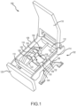
- FIG. 1 schematically illustrates a perspective view of a seat assembly 100 that may be used in an aircraft, a train, a bus or some other form of transportation.
- the seat assembly 100 may be connected to a floor via a base substructure 102 which, in various embodiments, may include a first lateral rail 104 and a second lateral rail 106 that extend laterally across a width of a seat frame 108 and provide structure upon which to secure the seat frame 108.
- the seat frame 108 includes a front member 110 and a rear member 112, connected by a left member 114 and a right member 116, the collection of which forms a generally square or rectangular structure.
- a back frame 118 and a foot frame 120 may be secured to the seat frame 108 and configured for reclining or retracting in typical fashion.
- a first rod 122 extends from the front member 110 to the rear member 112 and is attached thereto using suitable means, such as, for example, welding or bolting.
- a second rod 124 extends from the front member 110 to the rear member 112 and is attached thereto using suitable means.
- a first sleeve member 126 is employed to couple the first rod 122 to the first lateral rail 104 and a second sleeve member 128 is employed to couple the first rod 122 to the second lateral rail 106.
- a third sleeve member 130 is employed to couple the second rod 124 to the first lateral rail 104 and a fourth sleeve member 132 is employed to couple the second rod 124 to the second lateral rail 106.
- each of the first sleeve member 126, the second sleeve member 128, the third sleeve member 130 and the fourth sleeve member 132 are configured to enable the seat frame 108 to translate forward and backward with respect to the base substructure 102.
- each of the first sleeve member 126, the second sleeve member 128, the third sleeve member 130 and the fourth sleeve member 132 comprise a sliding structure (e.g ., a pillow block) that enable the first rod 122 and the second rod 124 to slide forward and backward through the corresponding sleeve members.
- a sliding structure e.g ., a pillow block
- an inertial lock 152 is slidably disposed on the first rod 122 and positioned intermediate the first sleeve member 126 and the second sleeve member 128.
- the inertial lock 152 is maintained in position on the first rod 122 without connection to the first sleeve member 126 or to the second sleeve member 128.
- a first gap 134 is allowed to occur between the first sleeve member 126 and the inertial lock 152 and a second gap 136 is allowed to occur between the second sleeve member 128 and the inertial lock 152.
- first gap 134 and the second gap 136 enable acceleration of the inertial lock 152 in the event of a rapid dynamic event, such as a crash.
- a second inertial lock 154 may be slidably disposed on the second rod 124 and positioned between third sleeve member 130 and the fourth sleeve member 132.
- the second inertial lock 154 may be described as having the same positional and mounting characteristics described above with respect to the inertial lock 152.
- an inertial lock assembly 150 may be defined as comprising the first rod 122 and the inertial lock 152.
- the inertial lock assembly may further be defined as including the first sleeve member 126 and the second sleeve member 128.
- the inertial lock assembly 250 includes a rod 222, an inertial lock 252 and a first sleeve member 226 and a second sleeve member 228.
- the inertial lock 252 includes a housing 260 having an inner surface 262.
- the inner surface 262 defines a triangular shaped segment 264 that extends in axisymmetric fashion about the inner surface of the housing 260.
- the triangular shaped segment 264 may include, in various embodiments, an apex 266 and a first portion 268 (or first side) and a second portion 270 (or second side).
- the first portion 268 defines a first conical section 267 extending from the apex 266 to a first end 278 spaced longitudinally (or axially) from the apex 266.
- the second portion 270 defines a second conical section 269 extending from the apex 266 to a second end 280 spaced longitudinally (or axially) from the apex 266, with the apex 266 being disposed intermediate ( e.g ., in between) the first end 278 and the second end 280.
- the triangular shaped segment 264 is raised on a base portion 272, such that the triangular shaped segment 264 (or the base leg of the triangle forming the segment) is positioned radially inward of and intermediate a first annular portion 274 and a second annular portion 276.
- the disclosure contemplates the inner surface 262 being defined by surfaces having various degrees of curvature - e.g., the first portion 268 (or first side) and the second portion 270 (or the second side) need not be defined by straight sides or surfaces, but may be defined by sides or surfaces having various degrees of convex or concave curvature with respect to a longitudinal axis L extending through the housing 260.
- first portion 268 and the second portion 270 define an angle 271 with respect to the longitudinal axis L of between about five degrees (5°) and about nine degrees (9°) and, in various embodiments, of about seven degrees (7°).
- the inertial lock 252 component of the inertial lock assembly 250 further includes, a biasing member 282 (e.g., a coil spring) configured for positioning proximate a central portion of the housing 260 and, in order of installation from both sides of the housing 260, first and second washers 284, first and second binding members 286 ( e.g., first and second pluralities of ball bearings), first and second sliding members 288 ( e.g., collars), third and fourth washers 290 and first and second retaining members 292 (e.g., circlips).
- a biasing member 282 e.g., a coil spring
- the inertial lock assembly 350 in various embodiments, includes a rod 322, an inertial lock 352 and a first sleeve member 326 and a second sleeve member 328.
- the inertial lock 352 includes a housing 360 and various subcomponents within the housing 360, including a biasing member 382 (e.g., a coil spring), first and second washers 384, first and second binding members 386 (e.g., first and second pluralities of ball bearings), first and second sliding members 388 (e.g., collars), third and fourth washers 390 and first and second retaining members 392 (e.g., circlips).
- the subcomponents are positioned symmetric about an apex 366 on an inner surface 362 of the housing 360, though non-symmetric positioning of the subcomponents is contemplated by the disclosure.
- the disclosure also contemplates embodiments using fewer or greater numbers of the subcomponents identified above - e.g., one or more of the first and second washers 384 and the third and fourth washers 390 may be eliminated in various embodiments.
- the housing 360 includes the characteristics and geometric features of the housing 260, described above with reference to FIG. 2C , and so are not repeated.
- the inertial lock 352 in various embodiments, is positioned between the first sleeve member 326 and the second sleeve member 328.
- a first gap 334 and a second gap 336 are provided to permit the inertial lock 352 to accelerate during a rapid dynamic event, such as a crash, prior to contacting one of the first sleeve member 326 and the second sleeve member 328.
- no such gaps are provided, as the first and second sliding members 388 are configured to accelerate within the housing 360 to provide the locking effect regardless.
- the first and second sliding members 388 and are separated by a first spacing 394 and a second spacing 396 from their respective first end 378 and second end 380.
- the biasing member 382 functions to ensure the first spacing 394 and the second spacing 396 are present by urging the first and second sliding members 388 away from their respective first end 378 and second end 380 of the inner surface 362 of the housing 360.
- the biasing member 382 also functions to urge the first and second binding members 386 in a direction away from the apex 366 to prevent inadvertent binding during normal operation ( i.e., during everyday operation absent a rapid deceleration event).
- one of the first and second sliding members 388 will accelerate within the housing 360, depending on the direction of deceleration, thereby driving one of the corresponding first and second binding members 386 into the inner surface 362 of the housing and against the rod 322, such that the housing 360 is prevented from translating farther along the rod 322.
- a sleeve member 389 will rapidly accelerate in the same direction, as indicated by the arrow A.
- the rapid acceleration of the sleeve member 389 will drive a binding member 395, corresponding to the sleeve member 389, into an angled portion 368 (e.g., a conical section) of the inner surface 362 toward the apex 366.
- the tapering feature of the angled portion 368 will cause the binding member 395 (e.g., a plurality of ball bearings) to bind the housing 360 against the tracking rod 322.
- the seat assembly 100 is prevented from further motion with respect to the base substructure 102 (attached to the floor) by virtue of the first sleeve member 126 (for deceleration toward the forward direction) and the second sleeve member 128 (for deceleration toward the aft direction) being secured to the base substructure 102 ( e.g ., through the first lateral rail 104 and the second lateral rail 106, respectively).
- the direction of deceleration is opposite the direction indicated by the arrow D, the difference being the subcomponents on the opposite side of the apex 366 being the functioning elements resulting in the locking of the inertial lock assembly 350.
- the materials used to construct the housing 360 and the first and second binding members 386 may be advantageously selected to hasten the binding process.
- the housing 360 is constructed of a softer or more deformable material than the first and second binding members 386 to enable the binding members to be driven into and deform the inner surface 362 of the housing 360.
- the housing 360 is constructed using aluminum or an aluminum alloy and the first and second binding members 386 are constructed from steel or stainless steel - e.g., the first and second binding members 386 may comprise first and second pluralities of stainless steel ball bearings or roller members.
- the first and second sliding members 388 are advantageously constructed of heavy and high-strength materials, such as, for example, steel or stainless steel, to facilitate development of sufficient inertial momentum during the rapid acceleration to drive the first and second binding members 386 into the housing 360 without themselves being deformed.
- These materials, or materials with similar strength characteristics and properties enable a seat assembly, such as the seat assembly 100 referred to in FIG. 1 , to operate normally for extended periods of time or complete lifetime cycles while, at the same time, possess the desired characteristics and properties to rapidly lock a seat assembly in place during a rapid deceleration event, such as a crash.
- FIG. 4 a schematic side view of an inertial lock assembly 450 is illustrated in accordance with various embodiments.
- the inertial lock assembly 450 shares many of the construction and operational characteristics described above, the main difference being the inertial lock assembly 450 is configured for operation in only one direction, whereas the inertial lock assembly 350 described with reference to FIG. 3 is configured for operation in two directions.
- the inertial lock assembly 450 in various embodiments, includes a rod 422, an inertial lock 452 and a first sleeve member 426 and a second sleeve member 428.
- the inertial lock 452 includes a housing 460 and various subcomponents within the housing 460, including a biasing member 482 (e.g., a coil spring), a washer 484, a binding member 486 (e.g., a plurality of ball bearings), and a sliding member 488 (e.g., collar).
- a retaining structure 483 is suitably fastened to the housing 460 to provide structure for the biasing member 482 to push against to maintain a spacing 494, similar to one of the first spacing 394 and the second spacing 396 described above with reference to FIG. 3 .
- the housing 460 includes the characteristics and geometric features of the housing 260, described above with reference to FIG.
- inertial lock assembly 450 is near identical to those described above with regard to the inertial lock assembly 350 referenced in FIG. 3 .
- references to "one embodiment”, “an embodiment”, “various embodiments”, etc. indicate that the embodiment described may include a particular feature, structure, or characteristic, but every embodiment may not necessarily include the particular feature, structure, or characteristic. Moreover, such phrases are not necessarily referring to the same embodiment. Further, when a particular feature, structure, or characteristic is described in connection with an embodiment, it is submitted that it is within the knowledge of one skilled in the art to affect such feature, structure, or characteristic in connection with other embodiments whether or not explicitly described. After reading the description, it will be apparent to one skilled in the relevant art(s) how to implement the disclosure in alternative embodiments.
Landscapes
- Engineering & Computer Science (AREA)
- Aviation & Aerospace Engineering (AREA)
- Transportation (AREA)
- Mechanical Engineering (AREA)
- Seats For Vehicles (AREA)
Claims (15)
- Ensemble verrou d'inertie (250, 350, 450), comprenant :une tige (222, 322, 422) orientée par rapport à un axe longitudinal ;un boîtier (260, 360, 460) disposé de manière coulissante autour de la tige (222, 322, 422), le boîtier (260, 360, 460) comportant une surface interne (262, 362) qui définit un segment de forme triangulaire (264) qui s'étend de manière axisymétrique autour de la surface interne (262 ; 362), le segment de forme triangulaire (264) ayant une première partie (268 ; 368) s'étendant d'un sommet (266, 366) à une première extrémité (278 ; 378) espacée longitudinalement du sommet (266, 366) ;un premier élément coulissant (288, 388) disposé de manière coulissante autour de la tige (222, 322, 422) et à l'intérieur du boîtier (260, 360, 460) à proximité de la première partie de la surface interne ; etun premier élément de liaison (486) disposé de manière coulissante autour de la tige (222, 322, 422) et à l'intérieur du boîtier (260, 360, 460), le premier élément de liaison (286, 386, 486) étant positionné entre le sommet (266, 366) et le premier élément coulissant (288, 388),un second élément coulissant disposé de manière coulissante autour de la tige (222, 322, 422) et à l'intérieur du boîtier (260, 360, 460) à proximité de la seconde partie de la surface interne ; etun second élément de liaison disposé de manière coulissante autour de la tige et à l'intérieur du boîtier (260, 360, 460), le second élément de liaison étant positionné entre le sommet (266, 366) et le second élément coulissant, et un premier élément de manchon positionné adjacent à une partie arrière du boîtier et connecté à la sous-structure et dans lequel le premier élément de liaison (286, 386, 486) est configuré pour lier le boîtier (260, 360, 460) contre un mouvement longitudinal par rapport à la tige (222, 322, 422).
- Ensemble verrou d'inertie selon la revendication 1, comprenant en outre un élément de sollicitation (382, 482) disposé à l'intérieur du boîtier (260, 360, 460) et configuré pour solliciter le premier élément de liaison (486) dans une première direction opposée au sommet (266, 366).
- Ensemble verrou d'inertie selon la revendication 2, comprenant en outre une première rondelle disposée entre l'élément de sollicitation (382, 482) et le premier élément de liaison (486).
- Ensemble verrou d'inertie selon la revendication 1, 2 ou 3, dans lequel le premier élément de liaison (486) comprend une première pluralité de paliers à billes, et éventuellement dans lequel le premier élément coulissant comprend un premier collier.
- Ensemble verrou d'inertie selon la revendication 1, 2, 3 ou 4, dans lequel la première partie définit une première section conique s'étendant du sommet (266, 366) à la première extrémité, et éventuellement
dans lequel la première section conique définit un premier angle par rapport à l'axe longitudinal s'étendant du sommet (266, 366) à la première extrémité. - Ensemble verrou d'inertie selon une quelconque revendication précédente, dans lequel la surface interne a une seconde partie s'étendant du sommet (266, 366) à une seconde extrémité espacée longitudinalement du sommet (266, 366), le sommet (266, 366) étant disposé entre la première extrémité et la seconde extrémité.
- Ensemble verrou d'inertie selon la revendication 1, dans lequel la seconde partie définit une seconde section conique s'étendant du sommet (266, 366) à la seconde extrémité.
- Ensemble verrou d'inertie selon la revendication 7, dans lequel la seconde section conique définit un second angle par rapport à l'axe longitudinal s'étendant du sommet (266, 366) à la seconde extrémité.
- Ensemble verrou d'inertie selon la revendication 8, comprenant en outre un élément de sollicitation (382, 482) disposé à l'intérieur du boîtier (260, 360, 460) et configuré pour solliciter le premier élément de liaison dans une première direction opposée au sommet (266, 366) et le second élément de liaison dans une seconde direction opposée au sommet (266, 366).
- Ensemble verrou d'inertie selon la revendication 9, dans lequel le premier élément de liaison comprend une première pluralité de paliers à billes et le second élément de liaison comprend une seconde pluralité de paliers à billes, et éventuellement
dans lequel le premier élément coulissant comprend un premier collier et le second élément coulissant comprend un second collier. - Ensemble siège, comprenant :un cadre de siège ayant un axe longitudinal ; et l'ensemble verrou d'inertie selon une quelconque revendication précédente ;la tige ayant une extrémité avant connectée à un élément avant du cadre de siège et une extrémité arrière connectée à un élément arrière du cadre de siège.
- Ensemble siège selon la revendication 11, comprenant en outre :une seconde partie de la surface interne, la seconde partie s'étendant du sommet (266, 366) à une seconde extrémité espacée longitudinalement du sommet (266, 366), le sommet (266, 366) étant disposé entre la première extrémité et le seconde extrémité ;un second élément coulissant disposé de manière coulissante autour de la tige et à l'intérieur du boîtier à proximité de la seconde partie de la surface interne ; etun second élément de liaison disposé de manière coulissante autour de la tige (222, 322, 422) et à l'intérieur du boîtier (260, 360, 460), le second élément de liaison étant positionné entre le sommet (266, 366) et le second élément coulissant.
- Ensemble siège selon la revendication 12, dans lequel la première partie définit une première section conique s'étendant du sommet à la première extrémité et la seconde partie définit une seconde section conique s'étendant du sommet à la seconde extrémité.
- Système d'assise pour un véhicule, comprenant :une sous-structure configurée pour être fixée à un plancher du véhicule ;un cadre de siège en prise coulissante avec la sous-structure, le cadre de siège étant configuré pour coulisser dans une direction avant et dans une direction arrière le long d'un axe longitudinal ;et un ensemble verrou d'inertie comprenant :une tige (222, 322, 422) orientée par rapport à un axe longitudinal ;un boîtier (260, 360, 460) disposé de manière coulissante autour de la tige (222, 322, 422), le boîtier (260, 360, 460) comportant une surface interne (262, 362) qui définit un segment de forme triangulaire (264) qui s'étend de manière axisymétrique autour de la surface interne (262 ; 362), le segment de forme triangulaire (264) ayant une première partie s'étendant d'un sommet à une première extrémité espacée longitudinalement du sommet (266, 366) ;un premier élément coulissant (288, 388) disposé de manière coulissante autour de la tige (222, 322, 422) et à l'intérieur du boîtier (260, 360, 460) à proximité de la première partie de la surface interne ; etun premier élément de liaison (486) disposé de manière coulissante autour de la tige (222, 322, 422) et à l'intérieur du boîtier (460), le premier élément de liaison (486) étant positionné entre le sommet (266, 366) et le premier élément coulissant (288, 388),la tige ayant une extrémité avant connectée à un élément avant du cadre de siège et une extrémité arrière connectée à un élément arrière du cadre de siège ;le boîtier comportant une seconde partie s'étendant du sommet jusqu'à une seconde extrémité espacée longitudinalement du sommet, le sommet étant disposé entre la première extrémité et la seconde extrémité ;un second élément coulissant disposé de manière coulissante autour de la tige (222, 322, 422) et à l'intérieur du boîtier (260, 360, 460) à proximité de la seconde partie de la surface interne ; etun second élément de liaison disposé de manière coulissante autour de la tige (222, 322, 422) et à l'intérieur du boîtier, le second élément de liaison étant positionné entre le sommet (266, 366) et le second élément coulissant.
- Système d'assise de véhicule selon la revendication 14, comprenant en outre un premier élément de manchon positionné adjacent à une partie arrière du boîtier et connecté à la sous-structure et un second élément de manchon positionné adjacent à une partie avant du boîtier et connecté à la sous-structure, et éventuellement
dans lequel le premier élément de liaison comprend une première pluralité de paliers à billes et le second élément de liaison comprend une seconde pluralité de paliers à billes et dans lequel le premier élément coulissant comprend un premier collier et le second élément coulissant comprend un second collier.
Applications Claiming Priority (1)
| Application Number | Priority Date | Filing Date | Title |
|---|---|---|---|
| US16/020,268 US10556525B2 (en) | 2018-06-27 | 2018-06-27 | Linear inertial lock |
Publications (2)
| Publication Number | Publication Date |
|---|---|
| EP3604030A1 EP3604030A1 (fr) | 2020-02-05 |
| EP3604030B1 true EP3604030B1 (fr) | 2023-12-06 |
Family
ID=67105918
Family Applications (1)
| Application Number | Title | Priority Date | Filing Date |
|---|---|---|---|
| EP19182960.5A Active EP3604030B1 (fr) | 2018-06-27 | 2019-06-27 | Verrou d'inertie linéaire |
Country Status (2)
| Country | Link |
|---|---|
| US (1) | US10556525B2 (fr) |
| EP (1) | EP3604030B1 (fr) |
Family Cites Families (9)
| Publication number | Priority date | Publication date | Assignee | Title |
|---|---|---|---|---|
| US4756577A (en) * | 1987-04-13 | 1988-07-12 | General Motors Corporation | Lock mechanism for a car seat back and recliner |
| JP2708723B2 (ja) * | 1994-06-20 | 1998-02-04 | デルタ工業株式会社 | 車両用シートのセーフティロック機構 |
| US5878859A (en) * | 1997-05-09 | 1999-03-09 | Lear Corporation | Manual vehicle seat adjuster with quick release clutch |
| DE19803448A1 (de) * | 1998-01-30 | 1999-08-05 | Schaeffler Waelzlager Ohg | Schaltbares Klemmgesperre |
| US5941494A (en) * | 1998-08-25 | 1999-08-24 | Meritor Automotive Canada Inc. | Inertial lock assembly for a seat track |
| US7748778B1 (en) | 2007-03-22 | 2010-07-06 | B/E Aerospace, Inc. | Inertia lock apparatus |
| GB201100604D0 (en) | 2011-01-14 | 2011-03-02 | Thompson Solutions Ltd J | Vehicle seat with locking apparatus |
| US9296481B2 (en) | 2011-01-14 | 2016-03-29 | Thompson Aero Seating Limited | Vehicle seat with locking apparatus |
| US9132753B1 (en) | 2013-05-29 | 2015-09-15 | Armorworks Enterprises LLC | Energy attenuating seat and seat extension |
-
2018
- 2018-06-27 US US16/020,268 patent/US10556525B2/en active Active
-
2019
- 2019-06-27 EP EP19182960.5A patent/EP3604030B1/fr active Active
Also Published As
| Publication number | Publication date |
|---|---|
| EP3604030A1 (fr) | 2020-02-05 |
| US10556525B2 (en) | 2020-02-11 |
| US20200001754A1 (en) | 2020-01-02 |
Similar Documents
| Publication | Publication Date | Title |
|---|---|---|
| CN101622153B (zh) | 车座、特别是商业车座 | |
| EP0877674B1 (fr) | Siege limitant la charge | |
| US7399037B2 (en) | Double-spar chassis for aircraft passenger seat | |
| EP3347273B1 (fr) | Mécanisme de retournement de dossier de siège consolidé | |
| JP2006312450A (ja) | 航空機用安全シート | |
| US8517464B2 (en) | Tray table stop assembly | |
| JPH07223594A (ja) | 乗物、特に航空機用の複数の隣接する座席を具備する構造 | |
| EP3490838B1 (fr) | Système de siège | |
| WO2006093644A1 (fr) | Appareil d’absorption d’energie | |
| CN111386225B (zh) | 两件式中心框架组件 | |
| EP3301022B1 (fr) | Ensemble base pivotante avec mouvement de rotation/avant/arrière et des caractéristiques de déformation | |
| EP3604030B1 (fr) | Verrou d'inertie linéaire | |
| CN110884398B (zh) | 固定座椅缓冲器 | |
| CN113710576B (zh) | 设置有安装在可变形部分上的齿条的飞行器座椅 | |
| JP7247602B2 (ja) | スライド装置 | |
| US9795527B2 (en) | Backrest fixation system and an electrically powered wheelchair comprising the same | |
| DE102009006717A1 (de) | Passagiersitzvorrichtung | |
| US11117502B2 (en) | Variable section bench for seat | |
| US20240116415A1 (en) | Device for constraining actuator motion during a dynamic event | |
| US9709121B2 (en) | Twin wire bending kinetic energy attenuation system | |
| WO2016060625A1 (fr) | Verrou à cisaillement optimisé pour sièges d'aéronef | |
| US11760491B1 (en) | Two-piece machine leg assembly for passenger seats | |
| US11679701B2 (en) | Seat back energy absorber | |
| EP4371816A1 (fr) | Système comprenant un ensemble de plateau de siège | |
| US20100181461A1 (en) | Vehicle seat track |
Legal Events
| Date | Code | Title | Description |
|---|---|---|---|
| PUAI | Public reference made under article 153(3) epc to a published international application that has entered the european phase |
Free format text: ORIGINAL CODE: 0009012 |
|
| STAA | Information on the status of an ep patent application or granted ep patent |
Free format text: STATUS: THE APPLICATION HAS BEEN PUBLISHED |
|
| AK | Designated contracting states |
Kind code of ref document: A1 Designated state(s): AL AT BE BG CH CY CZ DE DK EE ES FI FR GB GR HR HU IE IS IT LI LT LU LV MC MK MT NL NO PL PT RO RS SE SI SK SM TR |
|
| AX | Request for extension of the european patent |
Extension state: BA ME |
|
| STAA | Information on the status of an ep patent application or granted ep patent |
Free format text: STATUS: REQUEST FOR EXAMINATION WAS MADE |
|
| 17P | Request for examination filed |
Effective date: 20200804 |
|
| RBV | Designated contracting states (corrected) |
Designated state(s): AL AT BE BG CH CY CZ DE DK EE ES FI FR GB GR HR HU IE IS IT LI LT LU LV MC MK MT NL NO PL PT RO RS SE SI SK SM TR |
|
| RIC1 | Information provided on ipc code assigned before grant |
Ipc: B60N 2/433 20060101AFI20211122BHEP |
|
| STAA | Information on the status of an ep patent application or granted ep patent |
Free format text: STATUS: EXAMINATION IS IN PROGRESS |
|
| 17Q | First examination report despatched |
Effective date: 20220105 |
|
| GRAP | Despatch of communication of intention to grant a patent |
Free format text: ORIGINAL CODE: EPIDOSNIGR1 |
|
| STAA | Information on the status of an ep patent application or granted ep patent |
Free format text: STATUS: GRANT OF PATENT IS INTENDED |
|
| INTG | Intention to grant announced |
Effective date: 20230621 |
|
| GRAS | Grant fee paid |
Free format text: ORIGINAL CODE: EPIDOSNIGR3 |
|
| P01 | Opt-out of the competence of the unified patent court (upc) registered |
Effective date: 20230922 |
|
| GRAA | (expected) grant |
Free format text: ORIGINAL CODE: 0009210 |
|
| STAA | Information on the status of an ep patent application or granted ep patent |
Free format text: STATUS: THE PATENT HAS BEEN GRANTED |
|
| AK | Designated contracting states |
Kind code of ref document: B1 Designated state(s): AL AT BE BG CH CY CZ DE DK EE ES FI FR GB GR HR HU IE IS IT LI LT LU LV MC MK MT NL NO PL PT RO RS SE SI SK SM TR |
|
| REG | Reference to a national code |
Ref country code: GB Ref legal event code: FG4D |
|
| REG | Reference to a national code |
Ref country code: DE Ref legal event code: R096 Ref document number: 602019042680 Country of ref document: DE |
|
| REG | Reference to a national code |
Ref country code: CH Ref legal event code: EP |
|
| REG | Reference to a national code |
Ref country code: IE Ref legal event code: FG4D |
|
| REG | Reference to a national code |
Ref country code: LT Ref legal event code: MG9D |
|
| PG25 | Lapsed in a contracting state [announced via postgrant information from national office to epo] |
Ref country code: GR Free format text: LAPSE BECAUSE OF FAILURE TO SUBMIT A TRANSLATION OF THE DESCRIPTION OR TO PAY THE FEE WITHIN THE PRESCRIBED TIME-LIMIT Effective date: 20240307 |
|
| REG | Reference to a national code |
Ref country code: NL Ref legal event code: MP Effective date: 20231206 |
|
| PG25 | Lapsed in a contracting state [announced via postgrant information from national office to epo] |
Ref country code: LT Free format text: LAPSE BECAUSE OF FAILURE TO SUBMIT A TRANSLATION OF THE DESCRIPTION OR TO PAY THE FEE WITHIN THE PRESCRIBED TIME-LIMIT Effective date: 20231206 |
|
| PG25 | Lapsed in a contracting state [announced via postgrant information from national office to epo] |
Ref country code: ES Free format text: LAPSE BECAUSE OF FAILURE TO SUBMIT A TRANSLATION OF THE DESCRIPTION OR TO PAY THE FEE WITHIN THE PRESCRIBED TIME-LIMIT Effective date: 20231206 |
|
| PG25 | Lapsed in a contracting state [announced via postgrant information from national office to epo] |
Ref country code: LT Free format text: LAPSE BECAUSE OF FAILURE TO SUBMIT A TRANSLATION OF THE DESCRIPTION OR TO PAY THE FEE WITHIN THE PRESCRIBED TIME-LIMIT Effective date: 20231206 Ref country code: GR Free format text: LAPSE BECAUSE OF FAILURE TO SUBMIT A TRANSLATION OF THE DESCRIPTION OR TO PAY THE FEE WITHIN THE PRESCRIBED TIME-LIMIT Effective date: 20240307 Ref country code: ES Free format text: LAPSE BECAUSE OF FAILURE TO SUBMIT A TRANSLATION OF THE DESCRIPTION OR TO PAY THE FEE WITHIN THE PRESCRIBED TIME-LIMIT Effective date: 20231206 Ref country code: BG Free format text: LAPSE BECAUSE OF FAILURE TO SUBMIT A TRANSLATION OF THE DESCRIPTION OR TO PAY THE FEE WITHIN THE PRESCRIBED TIME-LIMIT Effective date: 20240306 |
|
| PG25 | Lapsed in a contracting state [announced via postgrant information from national office to epo] |
Ref country code: NL Free format text: LAPSE BECAUSE OF FAILURE TO SUBMIT A TRANSLATION OF THE DESCRIPTION OR TO PAY THE FEE WITHIN THE PRESCRIBED TIME-LIMIT Effective date: 20231206 |