EP3603944A1 - Method and system for producing a revolving body with glass fibre and carbon fibre, and resulting revolving body - Google Patents
Method and system for producing a revolving body with glass fibre and carbon fibre, and resulting revolving body Download PDFInfo
- Publication number
- EP3603944A1 EP3603944A1 EP18735620.9A EP18735620A EP3603944A1 EP 3603944 A1 EP3603944 A1 EP 3603944A1 EP 18735620 A EP18735620 A EP 18735620A EP 3603944 A1 EP3603944 A1 EP 3603944A1
- Authority
- EP
- European Patent Office
- Prior art keywords
- carbon fiber
- glass fiber
- revolving body
- manufacturing
- interior
- Prior art date
- Legal status (The legal status is an assumption and is not a legal conclusion. Google has not performed a legal analysis and makes no representation as to the accuracy of the status listed.)
- Granted
Links
Images







Classifications
-
- B—PERFORMING OPERATIONS; TRANSPORTING
- B29—WORKING OF PLASTICS; WORKING OF SUBSTANCES IN A PLASTIC STATE IN GENERAL
- B29C—SHAPING OR JOINING OF PLASTICS; SHAPING OF MATERIAL IN A PLASTIC STATE, NOT OTHERWISE PROVIDED FOR; AFTER-TREATMENT OF THE SHAPED PRODUCTS, e.g. REPAIRING
- B29C70/00—Shaping composites, i.e. plastics material comprising reinforcements, fillers or preformed parts, e.g. inserts
- B29C70/04—Shaping composites, i.e. plastics material comprising reinforcements, fillers or preformed parts, e.g. inserts comprising reinforcements only, e.g. self-reinforcing plastics
- B29C70/28—Shaping operations therefor
- B29C70/30—Shaping by lay-up, i.e. applying fibres, tape or broadsheet on a mould, former or core; Shaping by spray-up, i.e. spraying of fibres on a mould, former or core
- B29C70/34—Shaping by lay-up, i.e. applying fibres, tape or broadsheet on a mould, former or core; Shaping by spray-up, i.e. spraying of fibres on a mould, former or core and shaping or impregnating by compression, i.e. combined with compressing after the lay-up operation
-
- B—PERFORMING OPERATIONS; TRANSPORTING
- B29—WORKING OF PLASTICS; WORKING OF SUBSTANCES IN A PLASTIC STATE IN GENERAL
- B29C—SHAPING OR JOINING OF PLASTICS; SHAPING OF MATERIAL IN A PLASTIC STATE, NOT OTHERWISE PROVIDED FOR; AFTER-TREATMENT OF THE SHAPED PRODUCTS, e.g. REPAIRING
- B29C70/00—Shaping composites, i.e. plastics material comprising reinforcements, fillers or preformed parts, e.g. inserts
- B29C70/04—Shaping composites, i.e. plastics material comprising reinforcements, fillers or preformed parts, e.g. inserts comprising reinforcements only, e.g. self-reinforcing plastics
- B29C70/28—Shaping operations therefor
- B29C70/30—Shaping by lay-up, i.e. applying fibres, tape or broadsheet on a mould, former or core; Shaping by spray-up, i.e. spraying of fibres on a mould, former or core
- B29C70/32—Shaping by lay-up, i.e. applying fibres, tape or broadsheet on a mould, former or core; Shaping by spray-up, i.e. spraying of fibres on a mould, former or core on a rotating mould, former or core
-
- B—PERFORMING OPERATIONS; TRANSPORTING
- B29—WORKING OF PLASTICS; WORKING OF SUBSTANCES IN A PLASTIC STATE IN GENERAL
- B29C—SHAPING OR JOINING OF PLASTICS; SHAPING OF MATERIAL IN A PLASTIC STATE, NOT OTHERWISE PROVIDED FOR; AFTER-TREATMENT OF THE SHAPED PRODUCTS, e.g. REPAIRING
- B29C70/00—Shaping composites, i.e. plastics material comprising reinforcements, fillers or preformed parts, e.g. inserts
- B29C70/04—Shaping composites, i.e. plastics material comprising reinforcements, fillers or preformed parts, e.g. inserts comprising reinforcements only, e.g. self-reinforcing plastics
- B29C70/06—Fibrous reinforcements only
- B29C70/10—Fibrous reinforcements only characterised by the structure of fibrous reinforcements, e.g. hollow fibres
- B29C70/16—Fibrous reinforcements only characterised by the structure of fibrous reinforcements, e.g. hollow fibres using fibres of substantial or continuous length
- B29C70/22—Fibrous reinforcements only characterised by the structure of fibrous reinforcements, e.g. hollow fibres using fibres of substantial or continuous length oriented in at least two directions forming a two-dimensional [2D] structure
- B29C70/228—Fibrous reinforcements only characterised by the structure of fibrous reinforcements, e.g. hollow fibres using fibres of substantial or continuous length oriented in at least two directions forming a two-dimensional [2D] structure the structure being stacked in parallel layers with fibres of adjacent layers crossing at substantial angles
-
- B—PERFORMING OPERATIONS; TRANSPORTING
- B29—WORKING OF PLASTICS; WORKING OF SUBSTANCES IN A PLASTIC STATE IN GENERAL
- B29C—SHAPING OR JOINING OF PLASTICS; SHAPING OF MATERIAL IN A PLASTIC STATE, NOT OTHERWISE PROVIDED FOR; AFTER-TREATMENT OF THE SHAPED PRODUCTS, e.g. REPAIRING
- B29C70/00—Shaping composites, i.e. plastics material comprising reinforcements, fillers or preformed parts, e.g. inserts
- B29C70/04—Shaping composites, i.e. plastics material comprising reinforcements, fillers or preformed parts, e.g. inserts comprising reinforcements only, e.g. self-reinforcing plastics
- B29C70/28—Shaping operations therefor
- B29C70/40—Shaping or impregnating by compression not applied
- B29C70/42—Shaping or impregnating by compression not applied for producing articles of definite length, i.e. discrete articles
- B29C70/46—Shaping or impregnating by compression not applied for producing articles of definite length, i.e. discrete articles using matched moulds, e.g. for deforming sheet moulding compounds [SMC] or prepregs
- B29C70/48—Shaping or impregnating by compression not applied for producing articles of definite length, i.e. discrete articles using matched moulds, e.g. for deforming sheet moulding compounds [SMC] or prepregs and impregnating the reinforcements in the closed mould, e.g. resin transfer moulding [RTM], e.g. by vacuum
-
- B—PERFORMING OPERATIONS; TRANSPORTING
- B29—WORKING OF PLASTICS; WORKING OF SUBSTANCES IN A PLASTIC STATE IN GENERAL
- B29C—SHAPING OR JOINING OF PLASTICS; SHAPING OF MATERIAL IN A PLASTIC STATE, NOT OTHERWISE PROVIDED FOR; AFTER-TREATMENT OF THE SHAPED PRODUCTS, e.g. REPAIRING
- B29C70/00—Shaping composites, i.e. plastics material comprising reinforcements, fillers or preformed parts, e.g. inserts
- B29C70/68—Shaping composites, i.e. plastics material comprising reinforcements, fillers or preformed parts, e.g. inserts by incorporating or moulding on preformed parts, e.g. inserts or layers, e.g. foam blocks
- B29C70/86—Incorporated in coherent impregnated reinforcing layers, e.g. by winding
- B29C70/865—Incorporated in coherent impregnated reinforcing layers, e.g. by winding completely encapsulated
-
- B—PERFORMING OPERATIONS; TRANSPORTING
- B60—VEHICLES IN GENERAL
- B60B—VEHICLE WHEELS; CASTORS; AXLES FOR WHEELS OR CASTORS; INCREASING WHEEL ADHESION
- B60B3/00—Disc wheels, i.e. wheels with load-supporting disc body
- B60B3/08—Disc wheels, i.e. wheels with load-supporting disc body with disc body formed by two or more axially spaced discs
-
- B—PERFORMING OPERATIONS; TRANSPORTING
- B60—VEHICLES IN GENERAL
- B60B—VEHICLE WHEELS; CASTORS; AXLES FOR WHEELS OR CASTORS; INCREASING WHEEL ADHESION
- B60B3/00—Disc wheels, i.e. wheels with load-supporting disc body
- B60B3/12—Means of reinforcing disc bodies
-
- B—PERFORMING OPERATIONS; TRANSPORTING
- B60—VEHICLES IN GENERAL
- B60B—VEHICLE WHEELS; CASTORS; AXLES FOR WHEELS OR CASTORS; INCREASING WHEEL ADHESION
- B60B5/00—Wheels, spokes, disc bodies, rims, hubs, wholly or predominantly made of non-metallic material
- B60B5/02—Wheels, spokes, disc bodies, rims, hubs, wholly or predominantly made of non-metallic material made of synthetic material
-
- B—PERFORMING OPERATIONS; TRANSPORTING
- B29—WORKING OF PLASTICS; WORKING OF SUBSTANCES IN A PLASTIC STATE IN GENERAL
- B29C—SHAPING OR JOINING OF PLASTICS; SHAPING OF MATERIAL IN A PLASTIC STATE, NOT OTHERWISE PROVIDED FOR; AFTER-TREATMENT OF THE SHAPED PRODUCTS, e.g. REPAIRING
- B29C2791/00—Shaping characteristics in general
- B29C2791/001—Shaping in several steps
-
- B—PERFORMING OPERATIONS; TRANSPORTING
- B29—WORKING OF PLASTICS; WORKING OF SUBSTANCES IN A PLASTIC STATE IN GENERAL
- B29K—INDEXING SCHEME ASSOCIATED WITH SUBCLASSES B29B, B29C OR B29D, RELATING TO MOULDING MATERIALS OR TO MATERIALS FOR MOULDS, REINFORCEMENTS, FILLERS OR PREFORMED PARTS, e.g. INSERTS
- B29K2705/00—Use of metals, their alloys or their compounds, for preformed parts, e.g. for inserts
-
- B—PERFORMING OPERATIONS; TRANSPORTING
- B29—WORKING OF PLASTICS; WORKING OF SUBSTANCES IN A PLASTIC STATE IN GENERAL
- B29L—INDEXING SCHEME ASSOCIATED WITH SUBCLASS B29C, RELATING TO PARTICULAR ARTICLES
- B29L2031/00—Other particular articles
- B29L2031/32—Wheels, pinions, pulleys, castors or rollers, Rims
-
- B—PERFORMING OPERATIONS; TRANSPORTING
- B60—VEHICLES IN GENERAL
- B60B—VEHICLE WHEELS; CASTORS; AXLES FOR WHEELS OR CASTORS; INCREASING WHEEL ADHESION
- B60B2360/00—Materials; Physical forms thereof
- B60B2360/30—Synthetic materials
- B60B2360/34—Reinforced plastics
- B60B2360/341—Reinforced plastics with fibres
- B60B2360/3412—Glass fibres
-
- B—PERFORMING OPERATIONS; TRANSPORTING
- B60—VEHICLES IN GENERAL
- B60B—VEHICLE WHEELS; CASTORS; AXLES FOR WHEELS OR CASTORS; INCREASING WHEEL ADHESION
- B60B2360/00—Materials; Physical forms thereof
- B60B2360/30—Synthetic materials
- B60B2360/34—Reinforced plastics
- B60B2360/341—Reinforced plastics with fibres
- B60B2360/3416—Carbone fibres
-
- B—PERFORMING OPERATIONS; TRANSPORTING
- B60—VEHICLES IN GENERAL
- B60B—VEHICLE WHEELS; CASTORS; AXLES FOR WHEELS OR CASTORS; INCREASING WHEEL ADHESION
- B60B2360/00—Materials; Physical forms thereof
- B60B2360/30—Synthetic materials
- B60B2360/34—Reinforced plastics
- B60B2360/348—Resins
-
- B—PERFORMING OPERATIONS; TRANSPORTING
- B60—VEHICLES IN GENERAL
- B60B—VEHICLE WHEELS; CASTORS; AXLES FOR WHEELS OR CASTORS; INCREASING WHEEL ADHESION
- B60B2360/00—Materials; Physical forms thereof
- B60B2360/30—Synthetic materials
- B60B2360/36—Composite materials
- B60B2360/366—Composite materials comprising foams, e.g. synthetic or metal foams
Definitions
- the object of the present patent application is to register a method and system for manufacturing a revolving body with glass fiber and carbon fiber and resulting revolving body which includes notable innovations and advantages with respect to the techniques used up to now.
- the invention proposes the development of a method and system for manufacturing a revolving body with glass fiber and carbon fiber and resulting revolving body which, due to its arrangement, allows for the attainment of a revolving body made of glass fiber and also equipped with carbon fiber reinforcements arranged in a more suitable manner to notably increase its features with respect to different mechanical applications without this involving an impairment of other features or qualities, such as for example weight, manufacturing time, etc.
- Carbon fiber is known in the current prior art such as a synthetic fiber formed by fine filaments of 5-10 ⁇ m diameter and mainly composed of carbon.
- Each carbon fiber is the combination of thousands of carbon filaments. It is a synthetic fiber because it is manufactured from polyacrylonitrile. It has mechanical properties similar to steel and is as light as wood or plastic and, due to its hardness, it has a greater resistance to impact than the steel.
- the atomic structure of the carbon fiber is similar to graphite, consisting of layers of carbon atoms ordered in a hexagonal regular pattern. However, the difference is in the way in which these sheets intersect.
- Graphite is a crystalline material in which the sheets are situated parallel to one another in a regular manner. The chemical bonds between the sheets is relatively weak which provides the graphite with its softness and bright characteristics.
- carbon fiber is an amorphous material: the layers of carbon atoms are placed randomly, tightly or together. This integration of the layers of carbon is responsible for its high resistance.
- the main properties of this composite material are:
- Carbon fiber is considerably stronger and lighter in comparison to other traditional materials. Its resistance is almost three times greater than that of steel and its density is 4.5 times lower. Its structural design is flexible. It has chemical resistance and non-corrosive properties as well as good thermal and electric conductivity properties.
- Carbon fiber has been shown to be extremely useful as a reinforcing material for producing composite materials. Carbon fiber can be applied to components where lightness and strength are necessary, such as for example:
- the use of carbon fiber is especially important because the weight of an element in direct contact with the asphalt is significantly reduced. Reducing the mass of this element allows the dynamics, the direction and the response time of the suspension to be improved in the car.
- tests which the wheels with carbon fiber have to overcome are exactly the same as conventional tests: tests against curbs, exposure to ultraviolet rays, chemical exposure and extreme heat, etc.
- the filament winding process is also known which is a manufacturing technique for the production of composite materials, generally in the form of cylindrical structures which can be applied in the proposed invention. It consists of rolling filaments subjected to various tensions on a male mold or mandrel. The mandrel rotates while a carriage moves horizontally, depositing the fibers according to the desired pattern. The most common filaments are carbon or glass and are embedded in synthetic resin while they are deposited and rolled. The final result is an extremely efficient process for creating composite materials at low cost which are light and strong.
- This process is already used, for example, to produce large reservoirs, chemical tanks and fuel storage, tubes or pressure vessels with high resistance, such as the pipes of engines for rockets for example.
- the resin transfer method (RTM) is known in the prior art which can also be generally applied in the proposed invention.
- This process is used at present and mainly for the manufacture of large production runs and in sectors such as for example the automobile, aeronautical or wind sector amongst others.
- the present invention contributes to solving and resolving the present problem, since, due to its particular arrangement, it allows the attainment of a revolving body made of glass fiber and also equipped with carbon fiber reinforcements arranged in a more suitable manner to notably increase its features with respect to different mechanical applications without this involving an impairment of other features or qualities, such as for example weight, manufacturing time, etc.
- the initial fixing of the glass fiber layer in its initial contact section on the drum is carried out by means of generating a vacuum in the drum itself.
- the initial fixing of the glass fiber layer in its initial contact section on the drum is carried out by means of the use of a gluing means.
- the sectioning of the glass fiber layer supplied is carried out by means of the use of a rotating blade.
- the initial fixing of carbon fiber thread in its initial contact section on the roll takes place by means of a system of magnets or electromagnetically.
- the supply and rolling of the carbon fiber thread around and on at least one section of the formed surface of the roll takes place by means of a filament winding process.
- the heating of the roll with glass fiber and carbon fiber takes place with air at 100°C.
- the heating and subsequent cooling of the roll with glass fiber and carbon fiber takes place after impregnation with a binder.
- the method for manufacturing a revolving body with glass fiber and carbon fiber also comprises inserting an already manufactured disc preform which is added and adjusted concentrically to the first revolving body on its interior contour, said already manufactured disc preform having a sandwich structure with an interior disc piece and another exterior disc piece both made of carbon fiber and between which there is a central metal piece.
- the method for manufacturing a revolving body with glass fiber and carbon fiber also comprises the manufacture of a disc preform which, in turn, comprises:
- the method for manufacturing a revolving body with glass fiber and carbon fiber also comprises:
- the interior disc piece, and/or the central piece and/or the exterior disc piece are obtained by means of previous stamping.
- the resin is epoxy or similar.
- System for manufacturing a revolving body with glass fiber and carbon fiber suitable for executing a method of the invention comprising:
- the sectioning means comprise a circular blade.
- the drum has holes in its lateral surface and the layering unit also comprises means for empting the interior of the drum.
- the wrapping unit comprises guide means of the carbon fiber threads in the direction of the axial axis of the drum.
- system for manufacturing a revolving body with glass fiber and carbon fiber also comprises:
- the external molds are a membrane adaptable by air pressure to the interior mold.
- the glass fiber layering unit, the carbon fiber wrapping unit and the heat exchange unit are displaceable on guides and with a mutual position variable between them.
- the system for manufacturing a revolving body with glass fiber and carbon fiber includes means for inserting foam or similar into at least one space comprised between the interior disc piece and the exterior disc piece.
- First revolving body with glass fiber and carbon fiber resulting from a method for manufacturing of the invention and/or a system of manufacturing of the invention which is formed by a roll resulting from rolling and superimposing a glass fiber layer rolled around an axial axis, the threads of the glass fiber layer being parallel or oblique to said axial axis and which is essentially characterized in that it comprises at least one carbon fiber thread arranged, rolled and adhered on the lateral surface of the glass fiber roll and surrounding the lateral surface of glass fiber roll, the carbon fiber threads being perpendicular or oblique to the threads of the glass fiber of the roll and therefore there being no parallelism between them.
- the first revolving body with glass fiber and carbon fiber has a bottle-type geometry or similar, and enabled for carrying fluids in its interior.
- the revolving composite body with glass fiber and carbon fiber also has a disc preform adjusted concentrically on the interior contour of a first revolving body of the invention and, in turn, said disc preform comprising an inserted interior disc piece of carbon fiber concentric to and fitted in the interior contour of the first revolving body, a central metal piece concentric to said first revolving body and arranged on the interior disc piece and another exterior disc piece of carbon fiber concentric to the same first revolving body and arranged on the central piece and coupled and fitted in the interior disc piece.
- the first revolving body with glass fiber and carbon fiber includes a foam or similar in at least one space comprised between the interior disc piece and the exterior disc piece.
- the first revolving body with glass fiber and carbon fiber is a tire integrating an automotive wheel or similar, the central piece having screw elements enabled for its fixing on the vehicle.
- the method for manufacturing a revolving body with glass fiber and carbon fiber comprises different successive steps.
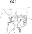
- fixing 101 takes place in its initial contact section of an initial glass fiber layer 1 on a drum 2, as is also represented schematically in Figure 2 .
- the glass fiber of the layer 1 applied on the drum 2 is dry and has no prior treatment. This contributes to an improvement in the economic cost of the method for manufacturing a revolving body with glass fiber and carbon fiber of the proposed invention.
- Said fixing 101 is preferably carried out with pneumatic means.
- said initial fixing 101 can be carried out by means of generating a vacuum in the drum 2 itself or by means of the use of a gluing means to adhere the initial contact section of the glass fiber layer 1 to the drum 2 itself.
- Supplying and rolling 102 of the same glass fiber layer 1 then takes place on the drum 2.
- Said supplying and rolling 102 is maintained until the required thickness on the same drum 2 is obtained, as can be schematically discerned in Figure 2 .
- the drum 2 rotates on its own axial axis 21 and with an orientation of the threads of the glass fiber layer 1 supplied parallel or with a certain obliqueness to the axial axis 21 of the drum 2 on which it is rolled and thus gives the resulting roll 3 orthotropic properties.
- Sectioning 104 of the supplied glass fiber layer 1 then takes place.
- Said sectioning 104 can be carried out by means of a rotating blade.
- Said lateral forming molds 51 are introduced into the roll 3 in the axial direction of the roll 3 itself in order to thus give the resulting roll 3 a suitable shape. This can be carried out owing to the fact that the drum 2 has a cylindrical geometry, with its flat and smooth cylindrical lateral surface as can be discerned from Figures 8 and 9 , and the axial directions of the roll 3 and the drum 2 coinciding as is detailed below.
- another initial fixing 106 (for example using a system of magnetic or electromagnetically) takes place and then a supply and rolling 107 of at least one carbon fiber thread 6 around and on at least one section of the formed surface of the roll 3. All of which can be carried out using a method known in the prior art as a filament winding process. According to what is established, in different preferred embodiments, the supply and rolling 107 of the carbon fiber thread 6 can be carried out around and on the full or partial extent of the formed surface of the roll 3.
- the carbon fiber of the thread 6 applied on the roll 3 is dry and has no prior treatment. This contributes to an improvement in the economic cost of the method for manufacturing a revolving body with glass fiber and carbon fiber of the proposed invention.
- Said supply and rolling 107 of the carbon fiber threads 6 takes place such that the orientation of the carbon fiber threads 6 is perpendicular to the axial axis 21 of the drum 2 on which it is rolled.
- guiding 107a or distribution of the carbon fiber thread 6 also takes place in the direction of the axial axis 21 of the drum 2, providing the required thickness in the sections of the formed surface of the roll 3 on which the carbon fiber threads 6 are rolled.
- pressing 110 of the resulting roll 3 takes place on counter molds 52 to maintain its generated shape.
- Heating 111 of the roll 3 with glass and carbon fiber is then carried out using hot air at approximately 100°C to provide structural rigidity and consistency for the shape attained. Cooling 112 of the same roll 3 is then carried out.
- impregnation of these fibers can be carried out with a suitable binder before heating 111.
- the removal 113 of the exterior counter molds 52 and of the forming molds 51 and the drum 2 then takes place from the interior of the initial roll 3. Said removal of the forming molds 51 and of the drum from the interior of the roll 3 can be carried out owing to the fact that the drum 2 has a cylindrical geometry with its flat and smooth cylindrical lateral surface as can be deduced from the Figures 8 and 9 and has been explained above. It is therefore not necessary to dismantle the forming molds 51 or the drum 2 for their removal 113.
- the first resulting revolving body 4 has different mechanical properties according to the direction in which it is measured.
- the method for manufacturing a revolving body with glass fiber and carbon fiber of the invention can also comprise some additional steps which result in the first revolving body 4 initially obtained being completed and transformed into a composite revolving body 5 which can be a tire of an automotive wheel or similar.
- said already manufactured disc preform 7 has a sandwich structure with an interior disc piece 71 and another exterior disc piece 73, both made of carbon fiber and between which there is a central metal piece 72.
- Said disc preform 7 incorporated in the first revolving body 4 means that said first revolving body 4 is complete and is transformed into the composite revolving body 5 previously referred to.
- the manufacture of the disc preform 7 takes place in the same method of the invention, as is indicated schematically in Figure 3 .
- positioning 304 of another exterior disc piece 73 of carbon fiber obtained by means of stamping is carried out concentrically to the first revolving body 4 and on the central piece 72 previously arranged and coupled and fitted to the interior disc piece 71.
- the foregoing produces the disc preform 7 arranged and adjusted concentrically on the interior contour of the first revolving body 4 with a sandwich structure of an interior disc piece 71 and another exterior disc piece 73 of carbon fiber with interior foam and a metallic disc piece 72 between the two.
- the disc preform 7 described therefore has the advantage of being able to be modified according to different needs or features required, merely by altering or modifying any of its integral elements.
- Figure 5 simultaneously represents the possibility of the disco preform 7 being manufactured in the same method of the invention (steps 301, 302, 303 and 304) or being incorporated in the method of the invention already manufactured externally (step 201). Both possibilities are included in the invention.
- the invention proceeds below jointly based on the first revolving body 4 and the previous disc preform 7, whether or not the disc preform 7 is manufactured in the same method of the invention, as is represented schematically in said Figure 5 , and in a preferred embodiment by means of a technique based on a resin transfer method.
- the external molds 82 can comprise a membrane adaptable by air pressure to the interior mold 81 and therefore exhibits deformability. This provides the advantage of a considerable simplification, facilitating automatization of its use and its maintenance, in addition to less waste. It also provides assistance with a movement release in the axial direction, simply by eliminating the air pressure affecting said external molds 82.
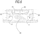
- Sealing 307 is then carried out prior to pressure injection 308 of a resin 17, for example epoxy, between the interior disc piece 71 and the exterior disc piece 73 and the first revolving body 4, as can also be schematically discerned in Figure 6 .
- a resin 17 for example epoxy
- the removal 309 of the interior mold 81 and of the external molds 82 then takes place and then extraction 310 of the resulting composite body 5.
- the presence of deformability in the external molds 82 can also even facilitate removal in the axial direction of said resulting composite body 5.
- said resulting composite body 5 is a tire of an automotive wheel or similar.
- the invention also includes a system suitable for the execution of the method previously described and with some of its elements already cited in the description already given of the method also included in the same invention.
- the system of the invention comprises a glass fiber layering unit 20, a carbon fiber wrapping unit 30 and a heat exchange unit 40.
- the glass fiber layering unit 20, the carbon fiber wrapping unit 30 and the heat exchange unit 40 are displaceable on guides and with a mutual position variable between them.
- the glass fiber layering unit 20 comprises supply means 2001 of a glass fiber layer 1, a drum 2 rotating on its own axial axis 21 and which has a cylindrical geometry with a flat and smooth cylindrical lateral surface as can also be deduced from Figures 8 and 9 and as is explained previously.
- Said flat and smooth cylindrical lateral surface 2 facilitates the supply and rolling 102 of the glass fiber layer 1 on said drum 2 and also involves said glass fiber layer 1 undergoing fewer tensions during the supply and rolling 102.
- the supply means 2001 and the rotating drum 2 are arranged and mutually connected for the rolling on the rotating drum 2 of the glass fiber layer 1 supplied from the supply means 2001 and the orientation of the threads of the glass fiber layer 1 being supplied parallel or oblique to the axial axis 21 and rotation of the drum 2, that is to say, not perpendicular.
- the glass fiber layering unit 20 also comprises fixing means of the first and last fiber layer and sectioning means (in this case a circular blade) of the glass fiber layer 1 supplied from the supply means 2001.
- the drum 2 has holes in its lateral surface and the layering unit 20 also comprises means for emptying the interior of the drum 2. The adhesion and fixing in its initial contact section of the glass fiber layer 1 is thereby ensured on the lateral surface of the drum 2.
- the carbon fiber wrapping unit 30 comprises supply means 3001 of at least one carbon fiber thread 6 around and on at least one section of the lateral surface of the resulting glass fiber roll 3, therefore around and on the total or partial extent of the lateral surface of the roll 3, the carbon fiber threads 6 being supplied perpendicular to the axial axis 21 of the drum 2 and it also has fixing means of the initial thread 6 to the first revolving body 4 formed in glass fiber.
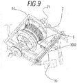
- the wrapping unit 30 also comprises guide means 3002 of the carbon fiber threads 6 and in the direction of the axial axis 21 of the drum 2 to provide the thickness required in the sections of the formed surface of the roll 3 on which the carbon fiber threads 6 are rolled, as is schematically represented in Figure 9 .
- the wrapping unit 30 also comprises sectioning means 3003 of the carbon fiber thread 6.
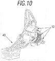
- the heat exchange unit 40 schematically represented in Figure 10 comprises molding means enabled for their introduction and pressing from a lateral position in the axial direction of the resulting glass fiber roll 3 and means for heating from the interior and exterior of the glass fiber roll 3.
- the system of the invention also comprises an interior mold 81 adapted to the interior contour of the first revolving body 4 and a plurality of external molds 82 adapted to the exterior contour of the first revolving body 4 and the uncovered face of the exterior disc piece 73 and enabled for its pressing and also comprises means for heating and injecting the resin 17.
- the external molds 82 comprises a membrane adaptable by air pressure and therefore they exhibit deformability.
- it is sufficient to eliminate the air pressure in the deformable membranes of said external molds 82.
- it would help simply eliminating the air pressure in said external molds 82 for a release of said movement in the axial direction.
- the system of the invention includes means for inserting foam or similar in at least one space 18 comprised between the interior disc piece 71 and the exterior disc piece 73 and represented in Figure 4 .
- the invention also includes the first revolving body 4 already previously cited and resulting from the method and/or the system previously described and with some of its elements already cited in the description already given of the method and system of the same invention.
- the first revolving body 4 is formed by a roll 3 resulting from a superimposition of a dry glass fiber layer 1 without prior treatment and rolled around an axial axis 121, the threads of the glass fiber layer 1 being parallel and oblique, that is to say, not parallel, to the axial axis 121 of said roll 3.
- it comprises at least one dry carbon fiber thread 6 without prior treatment arranged, rolled and adhered on the lateral surface of the glass fiber roll 3 and surrounding the lateral surface of the glass fiber roll 3.
- the threads of the carbon fiber 6 are perpendicular to the axial axis 121.
- the method and the system of manufacturing of the present invention involves the axial axis 121 of the roll 3 coinciding with the axial axis 21 of the drum 2 used in the method and system for manufacturing described.
- the described arrangement of the first revolving body 4 with the threads of the glass fiber of the layer 1 of the roll 3 and the threads of the carbon fiber 6 perpendicular or oblique, that is to say, not parallel to one another, give the first revolving body 4 increased resistance and at the same time with the resulting reduced weight, which considerably improves its features, and also gives the resulting first revolving body 4 orthotropic properties, that is to say, it has different mechanical properties according to the direction in which it is measured.
- the first revolving body 4 can, inter alia, have a bottle-type geometry or similar. In such case, the features of high resistance and reduced weight of the resulting first revolving body 4 can be very useful in the case of bottles enabled for the carrying of fluids in their interior and in conditions of high pressure.
- the invention also includes a revolving composite body 5.
- Said revolving composite body 5 comprises the foregoing first revolving body 4 which also includes a disc preform 7 adjusted concentrically on the interior contour of the first revolving body 4.
- the disc preform 7 comprises an interior disc piece 71 of carbon fiber inserted and concentric to the first revolving body itself 4, a central metallic reinforcing piece 72 concentric to said first revolving body 4 and arranged on the interior disc piece 71 and another exterior disc piece 73 of carbon fiber concentric to the same first revolving body 4 and arranged on the central piece 72 and the interior disc piece 71, in the sandwich structure.
- This arrangement explained and schematically represented in Figures 11 and 12 produces a composite body 5, achieved from the first revolving body 4.
- the composite body 5 corresponds to a tire integrating an automotive wheel or similar.
- the central piece 72 also includes screw elements 151 for its fixing on a vehicle, as is also represented schematically in Figure 12 .
- the exterior disc piece 73 is in the visible part of the tire, therefore exhibiting aesthetic functions and different exterior disc pieces 73 being able to be used interchangeably with one another according to the desired aesthetic appearance.
- the space 18 between the interior disc piece 71 and the exterior disc piece 73 is filled with foam, as is schematically represented in Figure 14 .
Landscapes
- Engineering & Computer Science (AREA)
- Mechanical Engineering (AREA)
- Chemical & Material Sciences (AREA)
- Composite Materials (AREA)
- Materials Engineering (AREA)
- Textile Engineering (AREA)
- Moulding By Coating Moulds (AREA)
- Laminated Bodies (AREA)
- Reinforced Plastic Materials (AREA)
Abstract
Description
- The object of the present patent application is to register a method and system for manufacturing a revolving body with glass fiber and carbon fiber and resulting revolving body which includes notable innovations and advantages with respect to the techniques used up to now.
- More specifically, the invention proposes the development of a method and system for manufacturing a revolving body with glass fiber and carbon fiber and resulting revolving body which, due to its arrangement, allows for the attainment of a revolving body made of glass fiber and also equipped with carbon fiber reinforcements arranged in a more suitable manner to notably increase its features with respect to different mechanical applications without this involving an impairment of other features or qualities, such as for example weight, manufacturing time, etc.
- Carbon fiber is known in the current prior art such as a synthetic fiber formed by fine filaments of 5-10 µm diameter and mainly composed of carbon.
- Each carbon fiber is the combination of thousands of carbon filaments. It is a synthetic fiber because it is manufactured from polyacrylonitrile. It has mechanical properties similar to steel and is as light as wood or plastic and, due to its hardness, it has a greater resistance to impact than the steel.
- The atomic structure of the carbon fiber is similar to graphite, consisting of layers of carbon atoms ordered in a hexagonal regular pattern. However, the difference is in the way in which these sheets intersect. Graphite is a crystalline material in which the sheets are situated parallel to one another in a regular manner. The chemical bonds between the sheets is relatively weak which provides the graphite with its softness and bright characteristics.
- Whereas, carbon fiber is an amorphous material: the layers of carbon atoms are placed randomly, tightly or together. This integration of the layers of carbon is responsible for its high resistance.
- The main properties of this composite material are:
- Very high mechanical resistance with a high elasticity modulus.
- Low density, in comparison to other materials such as for example steel.
- High production price.
- Resistance to external agents.
- High thermal isolation capacity.
- Resistance to temperature variations, preserving its shape, only if a thermostable matrix is used.
- Carbon fiber is considerably stronger and lighter in comparison to other traditional materials. Its resistance is almost three times greater than that of steel and its density is 4.5 times lower. Its structural design is flexible. It has chemical resistance and non-corrosive properties as well as good thermal and electric conductivity properties.
- Carbon fiber has been shown to be extremely useful as a reinforcing material for producing composite materials. Carbon fiber can be applied to components where lightness and strength are necessary, such as for example:
- Central section and other parts of airplanes.
- Windmill blades.
- Military applications.
- Decorations.
- Sports articles (tennis racquets, fishing rods, golf clubs, etc.).
- Automobile (sports vehicles, brakes and other parts, etc.).
- Others (bicycle frames, pressure vessels, mixture for concrete, etc.).
- In the automotive sector, the replacement of parts manufactured with conventional materials with parts manufactured with composite materials contributes to reducing the weight of the vehicle, greater efficiency in the consumption of fuel and an improvement in the ratio between power and weight of the vehicle, which translates into better performance of the vehicle.
- Historically, the use of composite materials in the automotive sector has been limited due, mainly, to the cycle times (production capacities). However, new regulations directly affecting CO2 emissions are driving the use of composite materials in this sector. One of the more effective strategies when the manufacturers of vehicles face the challenge of reducing CO2 emissions is reducing the weight of the vehicle where composite materials play an important role.
- Technology has revolutionized the manufacturing processes of automobiles, allowing components such as carbon fiber to be included in parts of cars when, up to a few years ago, it was unthinkable to make them out of carbon fiber.
- In the particular case of the wheels of the vehicles, the use of carbon fiber is especially important because the weight of an element in direct contact with the asphalt is significantly reduced. Reducing the mass of this element allows the dynamics, the direction and the response time of the suspension to be improved in the car.
- In general, reducing the weight of the car is already positive, but in the wheels, if possible, it is more important. Less suspended weight allows the lap times to be improved, while reducing the inertia and most importantly, means the suspension does not have as much work in order to maintain the contact of the car with the ground on complex surfaces.
- The tests which the wheels with carbon fiber have to overcome are exactly the same as conventional tests: tests against curbs, exposure to ultraviolet rays, chemical exposure and extreme heat, etc.
- In the prior art, the filament winding process is also known which is a manufacturing technique for the production of composite materials, generally in the form of cylindrical structures which can be applied in the proposed invention. It consists of rolling filaments subjected to various tensions on a male mold or mandrel. The mandrel rotates while a carriage moves horizontally, depositing the fibers according to the desired pattern. The most common filaments are carbon or glass and are embedded in synthetic resin while they are deposited and rolled. The final result is an extremely efficient process for creating composite materials at low cost which are light and strong.
- This process is already used, for example, to produce large reservoirs, chemical tanks and fuel storage, tubes or pressure vessels with high resistance, such as the pipes of engines for rockets for example.
- The resin transfer method (RTM) is known in the prior art which can also be generally applied in the proposed invention.
- It is a closed mold manufacturing process at low pressure and is normally formed of two parts, female and male and can be summarized in five steps:
- placing a dry fiber fabric (glass fiber, carbon fiber, aramid, etc.), in a mold and it is closed using mechanical forces such as a hydraulic press, screws, bolts or vacuum).
- injecting resin into the mold by means of a pump such that the fiber fabric is impregnated and the cavities of the mold are filled.
- drying the resin inlet and air outlet.
- heat application to cure the resin.
- when the necessary time has passed, the mold is opened and the part removed.
- Therefore, due to the possibility of molding the dry fibers before the injection of the resin, better orientation of the fibers is achieved, increasing the mechanical properties of the material.
- This process is used at present and mainly for the manufacture of large production runs and in sectors such as for example the automobile, aeronautical or wind sector amongst others.
- The present invention contributes to solving and resolving the present problem, since, due to its particular arrangement, it allows the attainment of a revolving body made of glass fiber and also equipped with carbon fiber reinforcements arranged in a more suitable manner to notably increase its features with respect to different mechanical applications without this involving an impairment of other features or qualities, such as for example weight, manufacturing time, etc.
- The present invention has been developed with the aim of providing a method for manufacturing a revolving body with glass fiber and carbon fiber which is essentially characterized in that it comprises:
- a) initially fixing a glass fiber layer in its initial contact section on a drum which rotates on its own axial axis.
- b) supplying and rolling the glass fiber layer on the drum and with an orientation of the threads of the glass fiber layer supplied parallel or oblique to the axial axis of said drum.
- c) interrupting the supply and rolling of the layer.
- d) sectioning the layer.
- e) introducing and pressing formed lateral molds in the axial direction of a glass fiber roll resulting from the previous steps and adhered to the drum, said axial direction coinciding with the direction of the axial axis of the drum.
- f) initially fixing at least one carbon fiber thread in its initial contact section on the roll
- g) supplying and rolling the carbon fiber thread around and on at least one section of the formed surface of the roll, the orientation of the carbon fiber threads being perpendicular to the axial axis of the drum.
- h) together with the supply and rolling of the carbon fiber thread, guiding or distribution of the carbon fiber thread also takes place in the direction of the axial axis of the drum.
- i) interrupting the supply and rolling of the carbon fiber threads.
- j) sectioning the carbon fiber threads supplied.
- k) pressing the resulting roll on counter molds maintaining the shape produced.
- l) heating and subsequently cooling the roll with glass fiber and carbon fiber.
- m) removing the counter molds and the lateral molds and the drum.
- n) extracting a resulting first revolving body of glass fiber and carbon fiber.
- Additionally, in the method for manufacturing a revolving body with glass fiber and carbon fiber, the initial fixing of the glass fiber layer in its initial contact section on the drum is carried out by means of generating a vacuum in the drum itself.
- Alternatively, in the method for manufacturing a revolving body with glass fiber and carbon fiber, the initial fixing of the glass fiber layer in its initial contact section on the drum is carried out by means of the use of a gluing means.
- Alternatively, in the method for manufacturing a revolving body with glass fiber and carbon fiber, the sectioning of the glass fiber layer supplied is carried out by means of the use of a rotating blade.
- Alternatively, in the method for manufacturing a revolving body with glass fiber and carbon fiber, the initial fixing of carbon fiber thread in its initial contact section on the roll takes place by means of a system of magnets or electromagnetically.
- Alternatively, in the method for manufacturing a revolving body with glass fiber and carbon fiber, the supply and rolling of the carbon fiber thread around and on at least one section of the formed surface of the roll takes place by means of a filament winding process.
- Alternatively, in the method for manufacturing a revolving body with glass fiber and carbon fiber, the heating of the roll with glass fiber and carbon fiber takes place with air at 100°C.
- Alternatively, in the method for manufacturing a revolving body with glass fiber and carbon fiber, the heating and subsequent cooling of the roll with glass fiber and carbon fiber takes place after impregnation with a binder.
- Additionally, the method for manufacturing a revolving body with glass fiber and carbon fiber also comprises inserting an already manufactured disc preform which is added and adjusted concentrically to the first revolving body on its interior contour, said already manufactured disc preform having a sandwich structure with an interior disc piece and another exterior disc piece both made of carbon fiber and between which there is a central metal piece.
- Additionally, the method for manufacturing a revolving body with glass fiber and carbon fiber also comprises the manufacture of a disc preform which, in turn, comprises:
- a) positioning an interior disc piece of carbon fiber, concentric and fitted in the interior contour of the first revolving body.
- b) positioning a central metal piece, concentric to the first revolving body and on the interior disc piece arranged previously.
- c) injecting polyurethane foam or similar on the interior disc piece.
- d) positioning another exterior disc piece of carbon fiber, concentric to the first revolving body and on the central piece arranged previously, and coupled and fitted in the interior disc piece.
- Additionally, the method for manufacturing a revolving body with glass fiber and carbon fiber also comprises:
- a) positioning an interior mold in the interior and adapted to the interior contour of the first revolving body.
- b) positioning a plurality of external molds adjusted and adapted on the exterior contour of the first revolving body and on the uncovered face of the exterior disc piece.
- c) sealing between the interior disc piece and exterior disc piece and the first revolving body itself.
- d) pressure-injecting a resin between the interior disc piece and exterior disc piece and the first revolving body itself.
- e) removing the interior mold and the external molds.
- f) extracting a resulting revolving composite body.
- Alternatively, in the method for manufacturing a revolving body with glass fiber and carbon fiber, the interior disc piece, and/or the central piece and/or the exterior disc piece are obtained by means of previous stamping.
- Alternatively, in the method for manufacturing a revolving body with glass fiber and carbon fiber, the resin is epoxy or similar.
- System for manufacturing a revolving body with glass fiber and carbon fiber, suitable for executing a method of the invention comprising:
- a glass fiber layering unit.
- a carbon fiber wrapping unit.
- a heat exchange unit.
- the glass fiber layering unit comprises:
- means for supplying a glass fiber layer and a drum rotating on its axial axis, the supply means and the rotating drum being arranged and connected to one another for the rolling on the rotating drum of the glass fiber layer supplied from the supply means, the orientation of the thread of the glass fiber layer being supplied parallel or oblique to the axial axis and rotation of the drum.
- means for fixing the first and last glass fiber layer.
- means for sectioning the glass fiber layer supplied from the supply means;
- the carbon fiber wrapping unit comprises:
- supply means of at least one carbon fiber thread around and on at least one section of the lateral surface of the resulting glass fiber roll, the carbon fiber threads being supplied perpendicular to the threads of the glass fiber layer of the roll rolled on the drum.
- means for fixing the first carbon fiber thread.
- means for sectioning the carbon fiber thread;
- the heat exchange unit comprises:
- molding means enabled for its introduction and pressing from a lateral position in the axial direction of the resulting glass fiber roll,
- means for heating from the interior and exterior of the glass fiber roll.
- Alternatively, in the system for manufacturing a revolving body with glass fiber and carbon fiber, the sectioning means comprise a circular blade.
- Alternatively, in the system for manufacturing a revolving body with glass fiber and carbon fiber, the drum has holes in its lateral surface and the layering unit also comprises means for empting the interior of the drum.
- Alternatively, in the system for manufacturing a revolving body with glass fiber and carbon fiber, the wrapping unit comprises guide means of the carbon fiber threads in the direction of the axial axis of the drum.
- Additionally, the system for manufacturing a revolving body with glass fiber and carbon fiber also comprises:
- an interior mold adapted to the interior contour of the first revolving body.
- a plurality of external molds adapted to the exterior contour of the first revolving body and to the uncovered face of the exterior disc piece and enabled for its pressing.
- means for heating and injecting resin.
- Alternatively, in the system for manufacturing a revolving body with glass fiber and carbon fiber, the external molds are a membrane adaptable by air pressure to the interior mold.
- Alternatively, in the system for manufacturing a revolving body with glass fiber and carbon fiber, the glass fiber layering unit, the carbon fiber wrapping unit and the heat exchange unit are displaceable on guides and with a mutual position variable between them.
- Alternatively, the system for manufacturing a revolving body with glass fiber and carbon fiber includes means for inserting foam or similar into at least one space comprised between the interior disc piece and the exterior disc piece.
- First revolving body with glass fiber and carbon fiber resulting from a method for manufacturing of the invention and/or a system of manufacturing of the invention which is formed by a roll resulting from rolling and superimposing a glass fiber layer rolled around an axial axis, the threads of the glass fiber layer being parallel or oblique to said axial axis and which is essentially characterized in that it comprises at least one carbon fiber thread arranged, rolled and adhered on the lateral surface of the glass fiber roll and surrounding the lateral surface of glass fiber roll, the carbon fiber threads being perpendicular or oblique to the threads of the glass fiber of the roll and therefore there being no parallelism between them.
- Alternatively, the first revolving body with glass fiber and carbon fiber has a bottle-type geometry or similar, and enabled for carrying fluids in its interior.
- Alternatively, the revolving composite body with glass fiber and carbon fiber also has a disc preform adjusted concentrically on the interior contour of a first revolving body of the invention and, in turn, said disc preform comprising an inserted interior disc piece of carbon fiber concentric to and fitted in the interior contour of the first revolving body, a central metal piece concentric to said first revolving body and arranged on the interior disc piece and another exterior disc piece of carbon fiber concentric to the same first revolving body and arranged on the central piece and coupled and fitted in the interior disc piece.
- Alternatively, the first revolving body with glass fiber and carbon fiber includes a foam or similar in at least one space comprised between the interior disc piece and the exterior disc piece.
- Alternatively, the first revolving body with glass fiber and carbon fiber is a tire integrating an automotive wheel or similar, the central piece having screw elements enabled for its fixing on the vehicle.
- Owing to the present invention, the attainment of a revolving body made of glass fiber and also equipped with carbon fiber reinforcements arranged in a more suitable manner to notably increase its features with respect to different mechanical applications without this involving an impairment of other features or qualities, such as for example weight, manufacturing time, etc.
- Other characteristics and advantages of the method and system for manufacturing a revolving body with glass fiber and carbon fiber and a resulting revolving body will be evident from the description of a preferred, but non-exclusive embodiment, which is illustrated by way of non-limiting example in the drawings which are enclosed, in which:
-
-
Figures 1 ,3 and5 are schematic and sequential views of preferred embodiments of the method for manufacturing a revolving body with glass fiber and carbon fiber of the present invention. -
Figure 2 is a schematic view of a detail of the fixing of a glass fiber layer on the drum, a preferred embodiment of the method and the system for manufacturing a revolving body with glass fiber and carbon fiber of the present invention. -
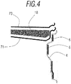
Figure 4 is a schematic view of the introduction of a material in the manner of foam into the spaces between the interior disc piece and the exterior disc piece in a preferred embodiment of the method and system for manufacturing a revolving body with glass fiber and carbon fiber of the present invention. -
Figure 6 is a schematic view of the arrangement in its operation of the interior mold and the exterior molds of a preferred embodiment of the method and system for manufacturing a revolving body with glass fiber and carbon fiber of the present invention. -
Figure 7 is a schematic view of an embodiment of the system for manufacturing a revolving body with glass fiber and carbon fiber of the present invention. -
Figure 8 is a schematic view of the layering unit of an embodiment of the system for manufacturing a revolving body with glass fiber and carbon fiber of the present invention. -
Figure 9 is a schematic view from different perspectives of the wrapping unit of a preferred embodiment of the system for manufacturing a revolving body with glass fiber and carbon fiber of the present invention. -
Figure 10 is a schematic view of the heat exchange unit of an embodiment of the system for manufacturing a revolving body with glass fiber and carbon fiber of the present invention. -
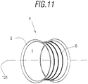
Figure 11 is a schematic view of a preferred embodiment of the first revolving body with glass fiber and carbon fiber of the present invention. -
Figure 12 is a schematic view of a preferred embodiment of the revolving composite body with glass fiber and carbon fiber of the present invention and in the manner of a tire for automotive wheels. -
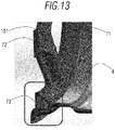
Figure 13 is a schematic view in greater detail of the fitting and coupling of the interior disc piece, the central piece and the exterior disc piece in the first revolving body, all integrated in the composite revolving body in the manner of a tire for automotive wheels. -
Figure 14 is a schematic view of the space filled with foam between the interior disc piece and exterior disc piece of the revolving composite body in the manner of a tire. - As is shown in the schematic representation of
Figure 1 , the method for manufacturing a revolving body with glass fiber and carbon fiber comprises different successive steps. - Firstly, fixing 101 takes place in its initial contact section of an initial glass fiber layer 1 on a
drum 2, as is also represented schematically inFigure 2 . As is included in the resin transfer method which can also be used in the method of the present invention as is explained below and even as is mentioned in the background of the present invention, the glass fiber of the layer 1 applied on thedrum 2 is dry and has no prior treatment. This contributes to an improvement in the economic cost of the method for manufacturing a revolving body with glass fiber and carbon fiber of the proposed invention. - Said fixing 101 is preferably carried out with pneumatic means. In other preferred embodiments, said initial fixing 101 can be carried out by means of generating a vacuum in the
drum 2 itself or by means of the use of a gluing means to adhere the initial contact section of the glass fiber layer 1 to thedrum 2 itself. - Supplying and rolling 102 of the same glass fiber layer 1 then takes place on the
drum 2. - Said supplying and rolling 102 is maintained until the required thickness on the
same drum 2 is obtained, as can be schematically discerned inFigure 2 . - The
drum 2 rotates on its ownaxial axis 21 and with an orientation of the threads of the glass fiber layer 1 supplied parallel or with a certain obliqueness to theaxial axis 21 of thedrum 2 on which it is rolled and thus gives the resultingroll 3 orthotropic properties. - Following successive passes during the rolling of the glass fiber layer 1 on the
drum 2, aninterruption 103 in the supply and rolling 102 of the glass fiber layer 1 is carried out. -
Sectioning 104 of the supplied glass fiber layer 1 then takes place. Said sectioning 104 can be carried out by means of a rotating blade. - The different successive steps described above produce a resulting
glass fiber roll 3, adhered to thedrum 2. - Introduction and pressing 105 of
lateral forming molds 51 in the resultingroll 3 then takes place by means of the use of compressors. - Said
lateral forming molds 51 are introduced into theroll 3 in the axial direction of theroll 3 itself in order to thus give the resulting roll 3 a suitable shape. This can be carried out owing to the fact that thedrum 2 has a cylindrical geometry, with its flat and smooth cylindrical lateral surface as can be discerned fromFigures 8 and9 , and the axial directions of theroll 3 and thedrum 2 coinciding as is detailed below. - Following the adoption of the final shape of the resulting
roll 3 owing to the introduction and pressing 105 of thelateral molds 51, another initial fixing 106 (for example using a system of magnetic or electromagnetically) takes place and then a supply and rolling 107 of at least onecarbon fiber thread 6 around and on at least one section of the formed surface of theroll 3. All of which can be carried out using a method known in the prior art as a filament winding process. According to what is established, in different preferred embodiments, the supply and rolling 107 of thecarbon fiber thread 6 can be carried out around and on the full or partial extent of the formed surface of theroll 3. - Similar to what was initially explained, and as is included in the resin transfer method, which can also be used in the method of the present invention as is explained below and even as is mentioned in the background of the invention, the carbon fiber of the
thread 6 applied on theroll 3 is dry and has no prior treatment. This contributes to an improvement in the economic cost of the method for manufacturing a revolving body with glass fiber and carbon fiber of the proposed invention. - Said supply and rolling 107 of the
carbon fiber threads 6 takes place such that the orientation of thecarbon fiber threads 6 is perpendicular to theaxial axis 21 of thedrum 2 on which it is rolled. - In said supply and rolling 107, guiding 107a or distribution of the
carbon fiber thread 6 also takes place in the direction of theaxial axis 21 of thedrum 2, providing the required thickness in the sections of the formed surface of theroll 3 on which thecarbon fiber threads 6 are rolled. - Following the supply and rolling 107 of the
carbon fiber threads 6 and when theroll 3 with itscarbon fiber threads 6 is already formed, theinterruption 108 of supply and rolling 107 takes place and then the sectioning 109 of thecarbon fiber threads 6. - Subsequently, pressing 110 of the resulting
roll 3 takes place oncounter molds 52 to maintain its generated shape. - Heating 111 of the
roll 3 with glass and carbon fiber is then carried out using hot air at approximately 100°C to provide structural rigidity and consistency for the shape attained. Cooling 112 of thesame roll 3 is then carried out. - In some preferred embodiments, according to the nature of the initial glass fiber or carbon fiber used, impregnation of these fibers can be carried out with a suitable binder before
heating 111. - The
removal 113 of theexterior counter molds 52 and of the formingmolds 51 and thedrum 2 then takes place from the interior of theinitial roll 3. Said removal of the formingmolds 51 and of the drum from the interior of theroll 3 can be carried out owing to the fact that thedrum 2 has a cylindrical geometry with its flat and smooth cylindrical lateral surface as can be deduced from theFigures 8 and9 and has been explained above. It is therefore not necessary to dismantle the formingmolds 51 or thedrum 2 for theirremoval 113. - Following the above, the
extraction 114 of the first resulting revolvingbody 4 of glass fiber and carbon fiber takes place. - Owing to the manufacturing method described, and owing to the resulting crossed arrangement of the glass fibers and carbon fibers, the first resulting revolving
body 4 has different mechanical properties according to the direction in which it is measured. - In other preferred embodiments, the method for manufacturing a revolving body with glass fiber and carbon fiber of the invention can also comprise some additional steps which result in the first revolving
body 4 initially obtained being completed and transformed into a composite revolvingbody 5 which can be a tire of an automotive wheel or similar. - Therefore,
insertion 201 of a disc preform 7 that was already previously manufactured takes place, as is indicated in the schematic representation ofFigure 1 which is added and adjusted concentrically to the first revolvingbody 4 on its interior contour. - For its part, said already manufactured disc preform 7, in turn, has a sandwich structure with an
interior disc piece 71 and anotherexterior disc piece 73, both made of carbon fiber and between which there is acentral metal piece 72. - Said disc preform 7 incorporated in the first revolving
body 4 means that said first revolvingbody 4 is complete and is transformed into the composite revolvingbody 5 previously referred to. - In other preferred and alternative embodiments, the manufacture of the disc preform 7 takes place in the same method of the invention, as is indicated schematically in
Figure 3 . - The case of manufacturing the disc perform 7 in the same method of the invention therefore involves the following other additional steps, represented schematically in
Figure 3 . - Positioning 301 of an
interior disc piece 71 of carbon fiber obtained by means of stamping and concentrically to the first revolvingbody 4 which fits concentrically into the interior contour of said first revolvingbody 4. - Positioning 302 of a
central metal piece 72 obtained by stamping and concentric to the first revolvingbody 4 and simultaneously on theinterior disc piece 71 previously arranged. - Then,
injection 303 or introduction of polyurethane foam or similar on theinterior disc piece 71, as is represented schematically inFigure 4 . - Then, positioning 304 of another
exterior disc piece 73 of carbon fiber obtained by means of stamping is carried out concentrically to the first revolvingbody 4 and on thecentral piece 72 previously arranged and coupled and fitted to theinterior disc piece 71. - The foregoing produces the disc preform 7 arranged and adjusted concentrically on the interior contour of the first revolving
body 4 with a sandwich structure of aninterior disc piece 71 and anotherexterior disc piece 73 of carbon fiber with interior foam and ametallic disc piece 72 between the two. - The disc preform 7 described therefore has the advantage of being able to be modified according to different needs or features required, merely by altering or modifying any of its integral elements.
-
Figure 5 simultaneously represents the possibility of the disco preform 7 being manufactured in the same method of the invention (steps - The invention proceeds below jointly based on the first revolving
body 4 and the previous disc preform 7, whether or not the disc preform 7 is manufactured in the same method of the invention, as is represented schematically in saidFigure 5 , and in a preferred embodiment by means of a technique based on a resin transfer method. - Therefore, positioning 305 of an
interior mold 81 in the interior and adapted to the interior contour of the first revolvingbody 4 takes place, as can be discerned schematically inFigure 6 . - After this, another
arrangement 306 of a plurality ofexternal molds 82 adjusted and adapted on the exterior contour of the first revolvingbody 4 and on the uncovered face of theexterior disc piece 73 takes place, as can also be discerned schematically inFigure 6 . - The
external molds 82 can comprise a membrane adaptable by air pressure to theinterior mold 81 and therefore exhibits deformability. This provides the advantage of a considerable simplification, facilitating automatization of its use and its maintenance, in addition to less waste. It also provides assistance with a movement release in the axial direction, simply by eliminating the air pressure affecting saidexternal molds 82. - Sealing 307 is then carried out prior to
pressure injection 308 of aresin 17, for example epoxy, between theinterior disc piece 71 and theexterior disc piece 73 and the first revolvingbody 4, as can also be schematically discerned inFigure 6 . - The
removal 309 of theinterior mold 81 and of theexternal molds 82 then takes place and thenextraction 310 of the resultingcomposite body 5. The presence of deformability in theexternal molds 82 can also even facilitate removal in the axial direction of said resultingcomposite body 5. - As has already been cited above, in a preferred embodiment, said resulting
composite body 5 is a tire of an automotive wheel or similar. - The invention also includes a system suitable for the execution of the method previously described and with some of its elements already cited in the description already given of the method also included in the same invention.
- As is represented schematically in
Figures 7 and9 , the system of the invention comprises a glassfiber layering unit 20, a carbonfiber wrapping unit 30 and aheat exchange unit 40. - In this preferred embodiment, the glass
fiber layering unit 20, the carbonfiber wrapping unit 30 and theheat exchange unit 40 are displaceable on guides and with a mutual position variable between them. - As is represented in
Figure 7 and from different perspectives, the glassfiber layering unit 20, in turn, comprises supply means 2001 of a glass fiber layer 1, adrum 2 rotating on its ownaxial axis 21 and which has a cylindrical geometry with a flat and smooth cylindrical lateral surface as can also be deduced fromFigures 8 and9 and as is explained previously. Said flat and smooth cylindricallateral surface 2 facilitates the supply and rolling 102 of the glass fiber layer 1 on saiddrum 2 and also involves said glass fiber layer 1 undergoing fewer tensions during the supply and rolling 102. - The supply means 2001 and the
rotating drum 2 are arranged and mutually connected for the rolling on therotating drum 2 of the glass fiber layer 1 supplied from the supply means 2001 and the orientation of the threads of the glass fiber layer 1 being supplied parallel or oblique to theaxial axis 21 and rotation of thedrum 2, that is to say, not perpendicular. - The glass
fiber layering unit 20 also comprises fixing means of the first and last fiber layer and sectioning means (in this case a circular blade) of the glass fiber layer 1 supplied from the supply means 2001. - In some preferred embodiments, as is represented schematically in
Figure 8 , thedrum 2 has holes in its lateral surface and thelayering unit 20 also comprises means for emptying the interior of thedrum 2. The adhesion and fixing in its initial contact section of the glass fiber layer 1 is thereby ensured on the lateral surface of thedrum 2. - In addition and as is represented schematically in
Figure 9 and from different perspectives, the carbonfiber wrapping unit 30 comprises supply means 3001 of at least onecarbon fiber thread 6 around and on at least one section of the lateral surface of the resultingglass fiber roll 3, therefore around and on the total or partial extent of the lateral surface of theroll 3, thecarbon fiber threads 6 being supplied perpendicular to theaxial axis 21 of thedrum 2 and it also has fixing means of theinitial thread 6 to the first revolvingbody 4 formed in glass fiber. - The
wrapping unit 30 also comprises guide means 3002 of thecarbon fiber threads 6 and in the direction of theaxial axis 21 of thedrum 2 to provide the thickness required in the sections of the formed surface of theroll 3 on which thecarbon fiber threads 6 are rolled, as is schematically represented inFigure 9 . - The
wrapping unit 30 also comprises sectioning means 3003 of thecarbon fiber thread 6. - The
heat exchange unit 40 schematically represented inFigure 10 comprises molding means enabled for their introduction and pressing from a lateral position in the axial direction of the resultingglass fiber roll 3 and means for heating from the interior and exterior of theglass fiber roll 3. - In another preferred embodiment of the system of the invention, it corresponds to the preferred embodiment of the method for manufacturing the
composite body 5. - To this end, as is represented schematically in
Figure 6 , the system of the invention also comprises aninterior mold 81 adapted to the interior contour of the first revolvingbody 4 and a plurality ofexternal molds 82 adapted to the exterior contour of the first revolvingbody 4 and the uncovered face of theexterior disc piece 73 and enabled for its pressing and also comprises means for heating and injecting theresin 17. - This is possible, as has been outlined previously, owing to the fact that the
external molds 82 comprises a membrane adaptable by air pressure and therefore they exhibit deformability. In order to eliminate the effect of the presence of saidexternal molds 82, it is sufficient to eliminate the air pressure in the deformable membranes of saidexternal molds 82. For example, in order to introduce or remove in the axial direction of the first revolvingbody 4 orcomposite body 5, it would help simply eliminating the air pressure in saidexternal molds 82 for a release of said movement in the axial direction. - In other preferred embodiments, in the case that said resulting
composite body 5 is a tire of an automotive wheel or similar, and the disc preform 7 is manufactured in the same first revolvingbody 4, the system of the invention includes means for inserting foam or similar in at least onespace 18 comprised between theinterior disc piece 71 and theexterior disc piece 73 and represented inFigure 4 . - The invention also includes the first revolving
body 4 already previously cited and resulting from the method and/or the system previously described and with some of its elements already cited in the description already given of the method and system of the same invention. - As is schematically represented in
Figure 11 , the first revolvingbody 4 is formed by aroll 3 resulting from a superimposition of a dry glass fiber layer 1 without prior treatment and rolled around anaxial axis 121, the threads of the glass fiber layer 1 being parallel and oblique, that is to say, not parallel, to theaxial axis 121 of saidroll 3. In addition, it comprises at least one drycarbon fiber thread 6 without prior treatment arranged, rolled and adhered on the lateral surface of theglass fiber roll 3 and surrounding the lateral surface of theglass fiber roll 3. The threads of thecarbon fiber 6 are perpendicular to theaxial axis 121. - The method and the system of manufacturing of the present invention involves the
axial axis 121 of theroll 3 coinciding with theaxial axis 21 of thedrum 2 used in the method and system for manufacturing described. - The described arrangement of the first revolving
body 4 with the threads of the glass fiber of the layer 1 of theroll 3 and the threads of thecarbon fiber 6 perpendicular or oblique, that is to say, not parallel to one another, give the first revolvingbody 4 increased resistance and at the same time with the resulting reduced weight, which considerably improves its features, and also gives the resulting first revolvingbody 4 orthotropic properties, that is to say, it has different mechanical properties according to the direction in which it is measured. - The first revolving
body 4 can, inter alia, have a bottle-type geometry or similar. In such case, the features of high resistance and reduced weight of the resulting first revolvingbody 4 can be very useful in the case of bottles enabled for the carrying of fluids in their interior and in conditions of high pressure. - The invention also includes a revolving
composite body 5. Said revolvingcomposite body 5 comprises the foregoing first revolvingbody 4 which also includes a disc preform 7 adjusted concentrically on the interior contour of the first revolvingbody 4. - This arrangement represented schematically in
Figure 12 produces a composite revolvingbody 5 achieved from the first revolvingbody 4. - As is schematically represented in greater detail in
Figure 13 , the disc preform 7, in turn, comprises aninterior disc piece 71 of carbon fiber inserted and concentric to the first revolving body itself 4, a central metallic reinforcingpiece 72 concentric to said first revolvingbody 4 and arranged on theinterior disc piece 71 and anotherexterior disc piece 73 of carbon fiber concentric to the same first revolvingbody 4 and arranged on thecentral piece 72 and theinterior disc piece 71, in the sandwich structure. This arrangement explained and schematically represented inFigures 11 and12 produces acomposite body 5, achieved from the first revolvingbody 4. - The coupling and fitting of the
interior disc piece 71, thecentral piece 72 and theexterior disc piece 73 of the disc preform 7 in the first revolvingbody 4, all integrated in thecomposite body 5 are schematically represented in greater detail inFigure 14 . - In addition, in this preferred embodiment, the
composite body 5 corresponds to a tire integrating an automotive wheel or similar. In such case, thecentral piece 72 also includesscrew elements 151 for its fixing on a vehicle, as is also represented schematically inFigure 12 . - Also in the case of the
composite body 5 corresponding to a tire, as is schematically represented inFigure 12 , theexterior disc piece 73 is in the visible part of the tire, therefore exhibiting aesthetic functions and differentexterior disc pieces 73 being able to be used interchangeably with one another according to the desired aesthetic appearance. - Also in this case, the
space 18 between theinterior disc piece 71 and theexterior disc piece 73 is filled with foam, as is schematically represented inFigure 14 . - The details, the shapes, the dimensions and other accessory elements as well as the materials used in the method and system for manufacturing a revolving body with glass fiber and carbon fiber and resulting revolving body of the invention can be conveniently substituted by others which are technically equivalent and do not depart from the essence of the invention nor from the scope defined by the claims which are included below.
Claims (26)
- A method for manufacturing a revolving body with glass fiber and carbon fiber, characterized in that it comprises:a) initially fixing (101) a dry glass fiber layer (1) without prior treatment in its initial contact section on a drum (2) which rotates on its own axial axis (21) and which exhibits a cylindrical geometry with a flat and smooth cylindrical lateral surface.b) supplying and rolling (102) the glass fiber layer (1) on the drum (2) and with an orientation of the threads of the glass fiber layer (1) supplied parallel or oblique to the axial axis (21) of said drum (2).c) interrupting (103) the supply and rolling (102) of the layer (1).d) sectioning (104) the layer (1).e) introducing and pressing (105) formed lateral molds (51) in the axial direction of a glass fiber roll (3) resulting from the previous steps and adhered to the drum (2), said axial direction coinciding with the direction of the axial axis (21) of the drum (2).f) initially fixing at least one dry carbon fiber thread (6) without prior treatment in its initial contact section on the roll (3).g) supplying and rolling (107) the carbon fiber thread (6) around and on at least one section of the formed surface of the roll (3), therefore around and on the total or partial extent of the formed surface of the same roll (3), the orientation of the carbon fiber threads (6) being perpendicular to the axial axis (21) of the drum (2).h) together with the supply and rolling (107) of the carbon fiber thread (6), guiding (107a) or distribution of the carbon fiber thread (6) also takes place in the direction of the axial axis (21) of the drum (2).i) interrupting (108) the supply and rolling (107) of the carbon fiber threads (6).j) sectioning (109) the carbon fiber threads (6) supplied.k) pressing (110) the resulting roll (3) on counter molds (52) maintaining the shape produced.l) heating (111) and subsequently cooling (112) the roll (3) with glass fiber and carbon fiber.m) removing (113) the counter molds (52) and the lateral molds (51) and the drum (2).n) extracting (114) a resulting first revolving body (4) of glass fiber and carbon fiber.
- The method for manufacturing a revolving body with glass fiber and carbon fiber according to claim 1, characterized in that the initial fixing (101) of the glass fiber layer (1) in its initial contact section on the drum (2) is carried out by means of generating a vacuum in the drum (2) itself.
- The method for manufacturing a revolving body with glass fiber and carbon fiber according to claim 1, characterized in that the initial fixing (101) of the glass fiber layer (1) in its initial contact section on the drum (2) is carried out by means of the use of a gluing means.
- The method for manufacturing a revolving body with glass fiber and carbon fiber according to claim 1, characterized in that the sectioning (104) of the glass fiber layer (1) supplied is carried out by means of the use of a rotating blade.
- The method for manufacturing a revolving body with glass fiber and carbon fiber according to claim 1, characterized in that the initial fixing (106) of at least one carbon fiber thread (6) in its initial contact section on the roll (3) takes place by means of a system of magnets or electromagnetically.
- The method for manufacturing a revolving body with glass fiber and carbon fiber according to claim 1, characterized in that the supply and rolling (107) of the carbon fiber thread (6) around and on at least one section of the formed surface of the roll (3) takes place by means of a filament winding process.
- The method for manufacturing a revolving body with glass fiber and carbon fiber according to claim 1, characterized in that the heating (111) of the roll (3) with glass fiber and carbon fiber takes place with air at 100°C.
- The method for manufacturing a revolving body with glass fiber and carbon fiber according to claim 1, characterized in that the heating (111) and subsequent cooling (112) of the roll (3) with glass fiber and carbon fiber takes place following impregnation with a binder.
- The method for manufacturing a revolving body with glass fiber and carbon fiber according to claim 1, characterized in that it further comprises insertion (201) of an already manufactured disc preform (7), which is added and adjusted concentrically to the first revolving body (4) on its interior contour, said already manufactured disc preform (7) having a sandwich structure with an interior disc piece (71) and another exterior disc piece (73) both made of carbon fiber, and between which a central metal piece (72) is located.
- The method for manufacturing a revolving body with glass fiber and carbon fiber according to claim 1, characterized in that it also comprises the manufacturing of a disc preform (7), which, in turn, comprises:a) positioning (301) an interior disc piece (71) of carbon fiber, concentric and fitted in the interior contour of the first revolving body (4).b) positioning (302) a central metal piece (72), concentric to the first revolving body (4) and on the interior disc piece (71) arranged previously.c) injecting (303) polyurethane foam or similar on the interior disc piece (71).d) positioning (304) another exterior disc piece (73) of carbon fiber, concentric to the first revolving body (4) and on the central piece (72) arranged previously, and coupled and fitted in the interior disc piece (71).
- The method for manufacturing a revolving body with glass fiber and carbon fiber according to claim 9 or 10, characterized in that it further comprises:a) positioning (305) an interior mold (81) in the interior and adapted to the interior contour of the first revolving body (4).b) positioning (306) a plurality of external molds (82) adjusted and adapted on the exterior contour of the first revolving body (4) and on the uncovered face of the exterior disc piece (73).c) sealing (307) between the interior disc piece (71) and exterior disc piece (73) and the first revolving body (4) itself.d) pressure-injecting (308) a resin (17) between the interior disc piece (71) and the exterior disc piece (73) and the first revolving body (4) itself.e) removing (309) the interior mold (81) and external molds (82).f) extracting (310) a resulting revolving composite body (5).
- The method for manufacturing a revolving body with glass fiber and carbon fiber according to claim 9 or 10, characterized in that the interior disc piece (71) and/or the central piece (72) and/or the exterior disc piece (73) are obtained by means of prior stamping.
- The method for manufacturing a revolving body with glass fiber and carbon fiber according to claim 11, characterized in that the resin (17) is epoxy or similar.
- A system for manufacturing a revolving body with glass fiber and carbon fiber suitable for the execution of the method of claim 1, which comprises:- a glass fiber layering unit (20).- a carbon fiber wrapping unit (30).- a heat exchange unit (40).and characterized in that:- the glass fiber layering unit (20) comprises:- means for supplying (2001) a glass fiber layer (1) and a drum (2) rotating on its axial axis (21), which exhibits a cylindrical geometry with a flat and smooth cylindrical lateral surface, the supply means (2001) and the rotating drum (2) being arranged and mutually connected for the rolling on the rotating drum (2) of the glass fiber layer (1) supplied from the supply means (2001), the orientation of the threads of the carbon fiber layer (1) being supplied parallel or oblique to the axial axis (21) and rotation of the drum (2).- means for fixing the first and last glass fiber layer (1).- means for sectioning the glass fiber layer (1) supplied from the supply means (2001);- the carbon fiber wrapping unit (30) comprises:- supply means (3001) of at least one carbon fiber thread (6) around and on at least one section of the lateral surface of the resulting glass fiber roll (3), the carbon fiber threads (6) being supplied perpendicular to the threads of the glass fiber layer (1) from the roll (3) rolled on the drum (2).- fixing means of the first carbon fiber thread (6).- sectioning means (3003) of the carbon fiber thread (6);- the heat exchange unit (40) comprises:- molding means to enable its introduction and pressing from a lateral position in the axial direction of the resulting glass fiber roll (3),- means for heating from the interior and exterior of the glass fiber roll (3).
- The system for manufacturing a revolving body with glass fiber and carbon fiber according to claim 14, characterized in that the sectioning means comprise a circular blade.
- The system for manufacturing a revolving body with glass fiber and carbon fiber according to claim 14, characterized in that the drum (2) has holes in its lateral surface, and the layering unit (20) further comprises means for emptying the interior of the drum (2).
- The system for manufacturing a revolving body with glass fiber and carbon fiber according to claim 14, characterized in that the wrapping unit (30) comprises guide means (3002) of the carbon fiber threads (6) in the direction of the axial axis (21) of the drum (2).
- The system for manufacturing a revolving body with glass fiber and carbon fiber according to claim 14, characterized in that it further comprises:- an interior mold (81) adapted to the interior contour of the first revolving body (4).- a plurality of external molds (82) adapted to the exterior contour of the first revolving body (4) and to the uncovered face of the exterior disc piece (73) and enabled for its pressing.- means for heating and injecting resin (17).
- The system for manufacturing a revolving body with glass fiber and carbon fiber according to claim 18, characterized in that the external molds (82) comprise a membrane adaptable by air pressure to the interior mold (81) and therefore they exhibit deformability.
- The system for manufacturing a revolving body with glass fiber and carbon fiber according to claim 14, characterized in that the glass fiber layering unit (20), the carbon fiber wrapping unit (30) and the heat exchange unit (40) are displaceable on guides and with a mutual position variable between the two.
- The system for manufacturing a revolving body with glass fiber and carbon fiber according to claim 18, characterized in that it includes means for inserting foam or similar into at least one space (18) comprised between the interior disc piece (71) and the exterior disc piece (73).
- A first revolving body with glass fiber and carbon fiber resulting from the method for manufacturing according to claim 1 and/or from the system of claim 14, which is formed by a roll (3) resulting from rolling and superimposing a dry glass fiber layer (1) without prior treatment and rolled around an axial axis (121), the threads of the glass fiber layer (1) being parallel or oblique to said axial axis (121), and characterized in that it comprises at least one dry carbon fiber thread (6) without prior treatment arranged, rolled and adhered on the lateral surface of the glass fiber roll (3) and surrounding the lateral surface of the glass fiber roll (3), the carbon fiber threads (6) being perpendicular or oblique to the glass fiber threads of the roll (3), and therefore there being no parallelism between them.
- The first revolving body with glass fiber and carbon fiber according to claim 22, characterized in that it exhibits a bottle-type geometry or similar and is enabled for carrying fluids in its interior.
- A composite revolving body with glass fiber and carbon fiber according to claim 22, resulting from the method for manufacturing of claim 11 and/or from the system of claim 19 or 22, characterized in that it further comprises a disc preform (7) adjusted concentrically on the interior contour of a first revolving body (4) of claim 23 or 24 and, in turn, said disc preform (7) comprising an inserted interior disc piece (71) of carbon fiber concentric to and fitted in the interior contour of the first revolving body (4), a central metal piece (72) concentric to said first revolving body (4) and arranged on the interior disc piece (71) and another exterior disc piece (76) of carbon fiber concentric to the same first revolving body (4) and arranged on the central piece (72) and coupled and fitted in the interior disc piece (71).
- The composite revolving body with glass fiber and carbon fiber according to claim 24, characterized in that it includes a foam or similar in at least one space (18) comprised between the interior disc piece (71) and the exterior disc piece (73).
- The composite revolving body with glass fiber and carbon fiber according to claim 24 or 25, characterized in that it is a tire integrating an automotive wheel or similar, the central piece (72) having screw elements (151) enabled for its fixing on a vehicle.
Applications Claiming Priority (2)
| Application Number | Priority Date | Filing Date | Title |
|---|---|---|---|
| ES201730539A ES2645752B1 (en) | 2017-03-31 | 2017-03-31 | PROCEDURE AND MANUFACTURING SYSTEM OF A REVOLUTION BODY WITH GLASS FIBER AND CARBON FIBER, AND RESULTING REVOLUTION BODY |
| PCT/ES2018/070257 WO2018178472A1 (en) | 2017-03-31 | 2018-03-27 | Method and system for producing a revolving body with glass fibre and carbon fibre, and resulting revolving body |
Publications (2)
| Publication Number | Publication Date |
|---|---|
| EP3603944A1 true EP3603944A1 (en) | 2020-02-05 |
| EP3603944B1 EP3603944B1 (en) | 2022-05-04 |
Family
ID=60484517
Family Applications (1)
| Application Number | Title | Priority Date | Filing Date |
|---|---|---|---|
| EP18735620.9A Active EP3603944B1 (en) | 2017-03-31 | 2018-03-27 | Method and system for manufacturing a revolving body with glass fiber and carbon fiber and resulting revolving body |
Country Status (3)
| Country | Link |
|---|---|
| EP (1) | EP3603944B1 (en) |
| ES (1) | ES2645752B1 (en) |
| WO (1) | WO2018178472A1 (en) |
Families Citing this family (2)
| Publication number | Priority date | Publication date | Assignee | Title |
|---|---|---|---|---|
| DE102019101046A1 (en) * | 2019-01-16 | 2020-07-16 | Liebherr-Components Biberach Gmbh | Rope drum for a winch and process for its manufacture |
| CN116113538A (en) * | 2020-06-04 | 2023-05-12 | 碳革命有限公司 | Improved carbon fiber wheel exterior |
Family Cites Families (7)
| Publication number | Priority date | Publication date | Assignee | Title |
|---|---|---|---|---|
| US3968996A (en) * | 1974-11-27 | 1976-07-13 | Wilcox Raymond J | Vehicle wheel |
| FR2755897A1 (en) * | 1996-11-15 | 1998-05-22 | Michelin & Cie | METHOD AND DEVICE FOR MANUFACTURING RIM PREFORM |
| US6347839B1 (en) * | 2000-09-25 | 2002-02-19 | Polymeric Corporation The | Composite rim |
| US20050104441A1 (en) * | 2003-11-19 | 2005-05-19 | Bertelson Peter C. | Fiber reinforced composite wheels |
| US20070272346A1 (en) * | 2006-05-23 | 2007-11-29 | Gkn Westland Aerospace, Inc. | System and method for consolidating dry fabric around a mandrel |
| US20100141022A1 (en) * | 2008-12-04 | 2010-06-10 | Tomer Hendel | Composite Wheel with Reinforced Core |
| JP6682544B2 (en) * | 2015-02-11 | 2020-04-15 | ムベア カルボ テック ゲーエムベーハーMubea Carbo Tech Gmbh | Method for producing fiber-reinforced annular body and apparatus for producing fiber-reinforced annular body |
-
2017
- 2017-03-31 ES ES201730539A patent/ES2645752B1/en not_active Withdrawn - After Issue
-
2018
- 2018-03-27 EP EP18735620.9A patent/EP3603944B1/en active Active
- 2018-03-27 WO PCT/ES2018/070257 patent/WO2018178472A1/en not_active Ceased
Also Published As
| Publication number | Publication date |
|---|---|
| ES2645752A1 (en) | 2017-12-07 |
| WO2018178472A1 (en) | 2018-10-04 |
| ES2645752B1 (en) | 2018-09-17 |
| EP3603944B1 (en) | 2022-05-04 |
| WO2018178472A8 (en) | 2019-10-17 |
Similar Documents
| Publication | Publication Date | Title |
|---|---|---|
| US8858857B2 (en) | Process for the rapid fabrication of composite gas cylinders and related shapes | |
| US10596772B2 (en) | Production of a plurality of different fiber composite components for high volumes in a continuous process | |
| CN110077013A (en) | Continue the composite material and its method of fibre three-dimensional braiding manufacture using preimpregnation glue connection | |
| EP3603944B1 (en) | Method and system for manufacturing a revolving body with glass fiber and carbon fiber and resulting revolving body | |
| CN208305844U (en) | The curing system of D braided composites cored screw spring | |
| CN101698326B (en) | Fiber-reinforced preform for resin transfer molding process, its composite component and its preparation method | |
| US20140342630A1 (en) | Woven fabric preforms and process for making the same | |
| TWI627056B (en) | Method for the manufacturing of a rim,the rim so manufactured,a running wheel including the rim and a bicycle having the running wheel | |
| WO2007095668A1 (en) | Composite structure | |
| JP5609249B2 (en) | High pressure tank manufacturing method, high pressure tank manufacturing apparatus, and high pressure tank | |
| JP2019155730A (en) | Manufacturing method of UD-like fiber reinforced composite sheet by filament winding (FW) method | |
| CN107097397A (en) | The manufacture method of core air bag, core air bag module and core air bag | |
| CN109843564A (en) | Composite sheet and its manufacturing method | |
| US20140083609A1 (en) | Method and apparatus for evacuation of large composite structures | |
| CN108081636A (en) | The production method of composite material spring | |
| KR20190134132A (en) | Composite rim of wheel for vehiclepiston pin and manufacturing method of the same | |
| CN115045038B (en) | Preparation method of full-closed top woven piece and preparation method of composite material piece of full-closed top woven piece | |
| NZ255607A (en) | Making structural components from resin impregnated fibre by winding fibre around spools | |
| CN106113531A (en) | A kind of anti-roll production technology sticking up CFRT one-way tape composite sheet | |
| CN107405795A (en) | Method and apparatus for manufacturing parison | |
| TW201311478A (en) | Composite material rim using single longitudinal-weaved carbon fiber and manufacturing method thereof | |
| CN118906496A (en) | Preparation method of aircraft bulkhead and aircraft bulkhead | |
| CN107719008A (en) | Manufacturing method of composite carbon fiber wheel frame | |
| CN107187072A (en) | The manufacture method of core air bag | |
| CN108859180B (en) | Glass fiber automobile plate spring and preparation and application thereof |
Legal Events
| Date | Code | Title | Description |
|---|---|---|---|
| STAA | Information on the status of an ep patent application or granted ep patent |
Free format text: STATUS: UNKNOWN |
|
| STAA | Information on the status of an ep patent application or granted ep patent |
Free format text: STATUS: THE INTERNATIONAL PUBLICATION HAS BEEN MADE |
|
| PUAI | Public reference made under article 153(3) epc to a published international application that has entered the european phase |
Free format text: ORIGINAL CODE: 0009012 |
|
| STAA | Information on the status of an ep patent application or granted ep patent |
Free format text: STATUS: REQUEST FOR EXAMINATION WAS MADE |
|
| 17P | Request for examination filed |
Effective date: 20191128 |
|
| AK | Designated contracting states |
Kind code of ref document: A1 Designated state(s): AL AT BE BG CH CY CZ DE DK EE ES FI FR GB GR HR HU IE IS IT LI LT LU LV MC MK MT NL NO PL PT RO RS SE SI SK SM TR |
|
| AX | Request for extension of the european patent |
Extension state: BA ME |
|
| STAA | Information on the status of an ep patent application or granted ep patent |
Free format text: STATUS: THE APPLICATION IS DEEMED TO BE WITHDRAWN |
|
| 18D | Application deemed to be withdrawn |
Effective date: 20191101 |
|
| DAV | Request for validation of the european patent (deleted) | ||
| DAX | Request for extension of the european patent (deleted) | ||
| STAA | Information on the status of an ep patent application or granted ep patent |
Free format text: STATUS: REQUEST FOR EXAMINATION WAS MADE |
|
| D18D | Application deemed to be withdrawn (deleted) | ||
| GRAP | Despatch of communication of intention to grant a patent |
Free format text: ORIGINAL CODE: EPIDOSNIGR1 |
|
| STAA | Information on the status of an ep patent application or granted ep patent |
Free format text: STATUS: GRANT OF PATENT IS INTENDED |
|
| RIC1 | Information provided on ipc code assigned before grant |
Ipc: B60B 3/12 20060101ALI20211111BHEP Ipc: B60B 3/08 20060101ALI20211111BHEP Ipc: B29K 705/00 20060101ALI20211111BHEP Ipc: B29L 31/32 20060101ALI20211111BHEP Ipc: B29C 70/22 20060101ALI20211111BHEP Ipc: B29C 70/86 20060101ALI20211111BHEP Ipc: B60B 5/02 20060101ALI20211111BHEP Ipc: B29C 70/48 20060101ALI20211111BHEP Ipc: B29C 70/32 20060101AFI20211111BHEP |
|
| INTG | Intention to grant announced |
Effective date: 20211213 |
|
| GRAS | Grant fee paid |
Free format text: ORIGINAL CODE: EPIDOSNIGR3 |
|
| GRAA | (expected) grant |
Free format text: ORIGINAL CODE: 0009210 |
|
| STAA | Information on the status of an ep patent application or granted ep patent |
Free format text: STATUS: THE PATENT HAS BEEN GRANTED |
|
| AK | Designated contracting states |
Kind code of ref document: B1 Designated state(s): AL AT BE BG CH CY CZ DE DK EE ES FI FR GB GR HR HU IE IS IT LI LT LU LV MC MK MT NL NO PL PT RO RS SE SI SK SM TR |
|
| REG | Reference to a national code |
Ref country code: CH Ref legal event code: EP |
|
| REG | Reference to a national code |
Ref country code: AT Ref legal event code: REF Ref document number: 1488585 Country of ref document: AT Kind code of ref document: T Effective date: 20220515 |
|
| REG | Reference to a national code |
Ref country code: IE Ref legal event code: FG4D Ref country code: DE Ref legal event code: R096 Ref document number: 602018034938 Country of ref document: DE |
|
| REG | Reference to a national code |
Ref country code: LT Ref legal event code: MG9D |
|
| REG | Reference to a national code |
Ref country code: NL Ref legal event code: MP Effective date: 20220504 |
|
| REG | Reference to a national code |
Ref country code: AT Ref legal event code: MK05 Ref document number: 1488585 Country of ref document: AT Kind code of ref document: T Effective date: 20220504 |
|
| PG25 | Lapsed in a contracting state [announced via postgrant information from national office to epo] |
Ref country code: SE Free format text: LAPSE BECAUSE OF FAILURE TO SUBMIT A TRANSLATION OF THE DESCRIPTION OR TO PAY THE FEE WITHIN THE PRESCRIBED TIME-LIMIT Effective date: 20220504 Ref country code: PT Free format text: LAPSE BECAUSE OF FAILURE TO SUBMIT A TRANSLATION OF THE DESCRIPTION OR TO PAY THE FEE WITHIN THE PRESCRIBED TIME-LIMIT Effective date: 20220905 Ref country code: NO Free format text: LAPSE BECAUSE OF FAILURE TO SUBMIT A TRANSLATION OF THE DESCRIPTION OR TO PAY THE FEE WITHIN THE PRESCRIBED TIME-LIMIT Effective date: 20220804 Ref country code: NL Free format text: LAPSE BECAUSE OF FAILURE TO SUBMIT A TRANSLATION OF THE DESCRIPTION OR TO PAY THE FEE WITHIN THE PRESCRIBED TIME-LIMIT Effective date: 20220504 Ref country code: LT Free format text: LAPSE BECAUSE OF FAILURE TO SUBMIT A TRANSLATION OF THE DESCRIPTION OR TO PAY THE FEE WITHIN THE PRESCRIBED TIME-LIMIT Effective date: 20220504 Ref country code: HR Free format text: LAPSE BECAUSE OF FAILURE TO SUBMIT A TRANSLATION OF THE DESCRIPTION OR TO PAY THE FEE WITHIN THE PRESCRIBED TIME-LIMIT Effective date: 20220504 Ref country code: GR Free format text: LAPSE BECAUSE OF FAILURE TO SUBMIT A TRANSLATION OF THE DESCRIPTION OR TO PAY THE FEE WITHIN THE PRESCRIBED TIME-LIMIT Effective date: 20220805 Ref country code: FI Free format text: LAPSE BECAUSE OF FAILURE TO SUBMIT A TRANSLATION OF THE DESCRIPTION OR TO PAY THE FEE WITHIN THE PRESCRIBED TIME-LIMIT Effective date: 20220504 Ref country code: BG Free format text: LAPSE BECAUSE OF FAILURE TO SUBMIT A TRANSLATION OF THE DESCRIPTION OR TO PAY THE FEE WITHIN THE PRESCRIBED TIME-LIMIT Effective date: 20220804 Ref country code: AT Free format text: LAPSE BECAUSE OF FAILURE TO SUBMIT A TRANSLATION OF THE DESCRIPTION OR TO PAY THE FEE WITHIN THE PRESCRIBED TIME-LIMIT Effective date: 20220504 |
|
| PG25 | Lapsed in a contracting state [announced via postgrant information from national office to epo] |
Ref country code: RS Free format text: LAPSE BECAUSE OF FAILURE TO SUBMIT A TRANSLATION OF THE DESCRIPTION OR TO PAY THE FEE WITHIN THE PRESCRIBED TIME-LIMIT Effective date: 20220504 Ref country code: PL Free format text: LAPSE BECAUSE OF FAILURE TO SUBMIT A TRANSLATION OF THE DESCRIPTION OR TO PAY THE FEE WITHIN THE PRESCRIBED TIME-LIMIT Effective date: 20220504 Ref country code: LV Free format text: LAPSE BECAUSE OF FAILURE TO SUBMIT A TRANSLATION OF THE DESCRIPTION OR TO PAY THE FEE WITHIN THE PRESCRIBED TIME-LIMIT Effective date: 20220504 Ref country code: IS Free format text: LAPSE BECAUSE OF FAILURE TO SUBMIT A TRANSLATION OF THE DESCRIPTION OR TO PAY THE FEE WITHIN THE PRESCRIBED TIME-LIMIT Effective date: 20220904 |
|
| PG25 | Lapsed in a contracting state [announced via postgrant information from national office to epo] |
Ref country code: SM Free format text: LAPSE BECAUSE OF FAILURE TO SUBMIT A TRANSLATION OF THE DESCRIPTION OR TO PAY THE FEE WITHIN THE PRESCRIBED TIME-LIMIT Effective date: 20220504 Ref country code: SK Free format text: LAPSE BECAUSE OF FAILURE TO SUBMIT A TRANSLATION OF THE DESCRIPTION OR TO PAY THE FEE WITHIN THE PRESCRIBED TIME-LIMIT Effective date: 20220504 Ref country code: RO Free format text: LAPSE BECAUSE OF FAILURE TO SUBMIT A TRANSLATION OF THE DESCRIPTION OR TO PAY THE FEE WITHIN THE PRESCRIBED TIME-LIMIT Effective date: 20220504 Ref country code: ES Free format text: LAPSE BECAUSE OF FAILURE TO SUBMIT A TRANSLATION OF THE DESCRIPTION OR TO PAY THE FEE WITHIN THE PRESCRIBED TIME-LIMIT Effective date: 20220504 Ref country code: EE Free format text: LAPSE BECAUSE OF FAILURE TO SUBMIT A TRANSLATION OF THE DESCRIPTION OR TO PAY THE FEE WITHIN THE PRESCRIBED TIME-LIMIT Effective date: 20220504 Ref country code: DK Free format text: LAPSE BECAUSE OF FAILURE TO SUBMIT A TRANSLATION OF THE DESCRIPTION OR TO PAY THE FEE WITHIN THE PRESCRIBED TIME-LIMIT Effective date: 20220504 Ref country code: CZ Free format text: LAPSE BECAUSE OF FAILURE TO SUBMIT A TRANSLATION OF THE DESCRIPTION OR TO PAY THE FEE WITHIN THE PRESCRIBED TIME-LIMIT Effective date: 20220504 |
|
| REG | Reference to a national code |
Ref country code: DE Ref legal event code: R097 Ref document number: 602018034938 Country of ref document: DE |
|
| PLBE | No opposition filed within time limit |
Free format text: ORIGINAL CODE: 0009261 |
|
| STAA | Information on the status of an ep patent application or granted ep patent |
Free format text: STATUS: NO OPPOSITION FILED WITHIN TIME LIMIT |
|
| PG25 | Lapsed in a contracting state [announced via postgrant information from national office to epo] |
Ref country code: AL Free format text: LAPSE BECAUSE OF FAILURE TO SUBMIT A TRANSLATION OF THE DESCRIPTION OR TO PAY THE FEE WITHIN THE PRESCRIBED TIME-LIMIT Effective date: 20220504 |
|
| 26N | No opposition filed |
Effective date: 20230207 |
|
| PG25 | Lapsed in a contracting state [announced via postgrant information from national office to epo] |
Ref country code: SI Free format text: LAPSE BECAUSE OF FAILURE TO SUBMIT A TRANSLATION OF THE DESCRIPTION OR TO PAY THE FEE WITHIN THE PRESCRIBED TIME-LIMIT Effective date: 20220504 |
|
| P01 | Opt-out of the competence of the unified patent court (upc) registered |
Effective date: 20230516 |
|
| PG25 | Lapsed in a contracting state [announced via postgrant information from national office to epo] |
Ref country code: MC Free format text: LAPSE BECAUSE OF FAILURE TO SUBMIT A TRANSLATION OF THE DESCRIPTION OR TO PAY THE FEE WITHIN THE PRESCRIBED TIME-LIMIT Effective date: 20220504 |
|
| REG | Reference to a national code |
Ref country code: CH Ref legal event code: PL |
|
| REG | Reference to a national code |
Ref country code: BE Ref legal event code: MM Effective date: 20230331 |
|
| PG25 | Lapsed in a contracting state [announced via postgrant information from national office to epo] |
Ref country code: LU Free format text: LAPSE BECAUSE OF NON-PAYMENT OF DUE FEES Effective date: 20230327 |
|
| REG | Reference to a national code |
Ref country code: IE Ref legal event code: MM4A |
|
| PG25 | Lapsed in a contracting state [announced via postgrant information from national office to epo] |
Ref country code: LI Free format text: LAPSE BECAUSE OF NON-PAYMENT OF DUE FEES Effective date: 20230331 Ref country code: IT Free format text: LAPSE BECAUSE OF FAILURE TO SUBMIT A TRANSLATION OF THE DESCRIPTION OR TO PAY THE FEE WITHIN THE PRESCRIBED TIME-LIMIT Effective date: 20220504 Ref country code: IE Free format text: LAPSE BECAUSE OF NON-PAYMENT OF DUE FEES Effective date: 20230327 Ref country code: CH Free format text: LAPSE BECAUSE OF NON-PAYMENT OF DUE FEES Effective date: 20230331 |
|
| PG25 | Lapsed in a contracting state [announced via postgrant information from national office to epo] |
Ref country code: BE Free format text: LAPSE BECAUSE OF NON-PAYMENT OF DUE FEES Effective date: 20230331 |
|
| PGFP | Annual fee paid to national office [announced via postgrant information from national office to epo] |
Ref country code: GB Payment date: 20240422 Year of fee payment: 7 |
|
| PGFP | Annual fee paid to national office [announced via postgrant information from national office to epo] |
Ref country code: DE Payment date: 20240429 Year of fee payment: 7 |
|
| PGFP | Annual fee paid to national office [announced via postgrant information from national office to epo] |
Ref country code: FR Payment date: 20240425 Year of fee payment: 7 |
|
| PG25 | Lapsed in a contracting state [announced via postgrant information from national office to epo] |
Ref country code: BG Free format text: LAPSE BECAUSE OF FAILURE TO SUBMIT A TRANSLATION OF THE DESCRIPTION OR TO PAY THE FEE WITHIN THE PRESCRIBED TIME-LIMIT Effective date: 20220504 |
|
| PG25 | Lapsed in a contracting state [announced via postgrant information from national office to epo] |
Ref country code: BG Free format text: LAPSE BECAUSE OF FAILURE TO SUBMIT A TRANSLATION OF THE DESCRIPTION OR TO PAY THE FEE WITHIN THE PRESCRIBED TIME-LIMIT Effective date: 20220504 |
|
| PG25 | Lapsed in a contracting state [announced via postgrant information from national office to epo] |
Ref country code: CY Free format text: LAPSE BECAUSE OF FAILURE TO SUBMIT A TRANSLATION OF THE DESCRIPTION OR TO PAY THE FEE WITHIN THE PRESCRIBED TIME-LIMIT; INVALID AB INITIO Effective date: 20180327 |
|
| PG25 | Lapsed in a contracting state [announced via postgrant information from national office to epo] |
Ref country code: HU Free format text: LAPSE BECAUSE OF FAILURE TO SUBMIT A TRANSLATION OF THE DESCRIPTION OR TO PAY THE FEE WITHIN THE PRESCRIBED TIME-LIMIT; INVALID AB INITIO Effective date: 20180327 |
|
| REG | Reference to a national code |
Ref country code: DE Ref legal event code: R119 Ref document number: 602018034938 Country of ref document: DE |
|
| GBPC | Gb: european patent ceased through non-payment of renewal fee |
Effective date: 20250327 |
|
| PG25 | Lapsed in a contracting state [announced via postgrant information from national office to epo] |
Ref country code: TR Free format text: LAPSE BECAUSE OF FAILURE TO SUBMIT A TRANSLATION OF THE DESCRIPTION OR TO PAY THE FEE WITHIN THE PRESCRIBED TIME-LIMIT Effective date: 20220504 |
|
| PG25 | Lapsed in a contracting state [announced via postgrant information from national office to epo] |
Ref country code: DE Free format text: LAPSE BECAUSE OF NON-PAYMENT OF DUE FEES Effective date: 20251001 |
|
| PG25 | Lapsed in a contracting state [announced via postgrant information from national office to epo] |
Ref country code: GB Free format text: LAPSE BECAUSE OF NON-PAYMENT OF DUE FEES Effective date: 20250327 |
|
| PG25 | Lapsed in a contracting state [announced via postgrant information from national office to epo] |
Ref country code: FR Free format text: LAPSE BECAUSE OF NON-PAYMENT OF DUE FEES Effective date: 20250331 |