EP3603826A1 - Method for calibrating an ultrasonic bonding machine - Google Patents
Method for calibrating an ultrasonic bonding machine Download PDFInfo
- Publication number
- EP3603826A1 EP3603826A1 EP18186443.0A EP18186443A EP3603826A1 EP 3603826 A1 EP3603826 A1 EP 3603826A1 EP 18186443 A EP18186443 A EP 18186443A EP 3603826 A1 EP3603826 A1 EP 3603826A1
- Authority
- EP
- European Patent Office
- Prior art keywords
- electrical
- calibration
- cal1
- cal2
- ultrasonic transducer
- Prior art date
- Legal status (The legal status is an assumption and is not a legal conclusion. Google has not performed a legal analysis and makes no representation as to the accuracy of the status listed.)
- Granted
Links
Images



Classifications
-
- G—PHYSICS
- G05—CONTROLLING; REGULATING
- G05B—CONTROL OR REGULATING SYSTEMS IN GENERAL; FUNCTIONAL ELEMENTS OF SUCH SYSTEMS; MONITORING OR TESTING ARRANGEMENTS FOR SUCH SYSTEMS OR ELEMENTS
- G05B19/00—Program-control systems
- G05B19/02—Program-control systems electric
- G05B19/18—Numerical control [NC], i.e. automatically operating machines, in particular machine tools, e.g. in a manufacturing environment, so as to execute positioning, movement or co-ordinated operations by means of program data in numerical form
- G05B19/182—Numerical control [NC], i.e. automatically operating machines, in particular machine tools, e.g. in a manufacturing environment, so as to execute positioning, movement or co-ordinated operations by means of program data in numerical form characterised by the machine tool function, e.g. thread cutting, cam making, tool direction control
-
- B—PERFORMING OPERATIONS; TRANSPORTING
- B06—GENERATING OR TRANSMITTING MECHANICAL VIBRATIONS IN GENERAL
- B06B—METHODS OR APPARATUS FOR GENERATING OR TRANSMITTING MECHANICAL VIBRATIONS OF INFRASONIC, SONIC, OR ULTRASONIC FREQUENCY, e.g. FOR PERFORMING MECHANICAL WORK IN GENERAL
- B06B3/00—Methods or apparatus specially adapted for transmitting mechanical vibrations of infrasonic, sonic, or ultrasonic frequency
- B06B3/02—Methods or apparatus specially adapted for transmitting mechanical vibrations of infrasonic, sonic, or ultrasonic frequency involving a change of amplitude
-
- B—PERFORMING OPERATIONS; TRANSPORTING
- B06—GENERATING OR TRANSMITTING MECHANICAL VIBRATIONS IN GENERAL
- B06B—METHODS OR APPARATUS FOR GENERATING OR TRANSMITTING MECHANICAL VIBRATIONS OF INFRASONIC, SONIC, OR ULTRASONIC FREQUENCY, e.g. FOR PERFORMING MECHANICAL WORK IN GENERAL
- B06B1/00—Methods or apparatus for generating mechanical vibrations of infrasonic, sonic, or ultrasonic frequency
- B06B1/02—Methods or apparatus for generating mechanical vibrations of infrasonic, sonic, or ultrasonic frequency making use of electrical energy
- B06B1/0207—Driving circuits
- B06B1/0223—Driving circuits for generating signals continuous in time
-
- B—PERFORMING OPERATIONS; TRANSPORTING
- B23—MACHINE TOOLS; METAL-WORKING NOT OTHERWISE PROVIDED FOR
- B23K—SOLDERING OR UNSOLDERING; WELDING; CLADDING OR PLATING BY SOLDERING OR WELDING; CUTTING BY APPLYING HEAT LOCALLY, e.g. FLAME CUTTING; WORKING BY LASER BEAM
- B23K20/00—Non-electric welding by applying impact or other pressure, with or without the application of heat, e.g. cladding or plating
- B23K20/10—Non-electric welding by applying impact or other pressure, with or without the application of heat, e.g. cladding or plating making use of vibrations, e.g. ultrasonic welding
-
- H—ELECTRICITY
- H10—SEMICONDUCTOR DEVICES; ELECTRIC SOLID-STATE DEVICES NOT OTHERWISE PROVIDED FOR
- H10W—GENERIC PACKAGES, INTERCONNECTIONS, CONNECTORS OR OTHER CONSTRUCTIONAL DETAILS OF DEVICES COVERED BY CLASS H10
- H10W72/00—Interconnections or connectors in packages
- H10W72/071—Connecting or disconnecting
- H10W72/0711—Apparatus therefor
-
- B—PERFORMING OPERATIONS; TRANSPORTING
- B06—GENERATING OR TRANSMITTING MECHANICAL VIBRATIONS IN GENERAL
- B06B—METHODS OR APPARATUS FOR GENERATING OR TRANSMITTING MECHANICAL VIBRATIONS OF INFRASONIC, SONIC, OR ULTRASONIC FREQUENCY, e.g. FOR PERFORMING MECHANICAL WORK IN GENERAL
- B06B2201/00—Indexing scheme associated with B06B1/0207 for details covered by B06B1/0207 but not provided for in any of its subgroups
- B06B2201/40—Indexing scheme associated with B06B1/0207 for details covered by B06B1/0207 but not provided for in any of its subgroups with testing, calibrating, safety devices, built-in protection, construction details
-
- B—PERFORMING OPERATIONS; TRANSPORTING
- B06—GENERATING OR TRANSMITTING MECHANICAL VIBRATIONS IN GENERAL
- B06B—METHODS OR APPARATUS FOR GENERATING OR TRANSMITTING MECHANICAL VIBRATIONS OF INFRASONIC, SONIC, OR ULTRASONIC FREQUENCY, e.g. FOR PERFORMING MECHANICAL WORK IN GENERAL
- B06B2201/00—Indexing scheme associated with B06B1/0207 for details covered by B06B1/0207 but not provided for in any of its subgroups
- B06B2201/70—Specific application
- B06B2201/72—Welding, joining, soldering
-
- G—PHYSICS
- G05—CONTROLLING; REGULATING
- G05B—CONTROL OR REGULATING SYSTEMS IN GENERAL; FUNCTIONAL ELEMENTS OF SUCH SYSTEMS; MONITORING OR TESTING ARRANGEMENTS FOR SUCH SYSTEMS OR ELEMENTS
- G05B2219/00—Program-control systems
- G05B2219/30—Nc systems
- G05B2219/37—Measurements
- G05B2219/37008—Calibration of measuring system, probe, sensor
-
- G—PHYSICS
- G05—CONTROLLING; REGULATING
- G05B—CONTROL OR REGULATING SYSTEMS IN GENERAL; FUNCTIONAL ELEMENTS OF SUCH SYSTEMS; MONITORING OR TESTING ARRANGEMENTS FOR SUCH SYSTEMS OR ELEMENTS
- G05B2219/00—Program-control systems
- G05B2219/30—Nc systems
- G05B2219/45—Nc applications
- G05B2219/45033—Wire bonding, wire wrap
-
- H—ELECTRICITY
- H10—SEMICONDUCTOR DEVICES; ELECTRIC SOLID-STATE DEVICES NOT OTHERWISE PROVIDED FOR
- H10W—GENERIC PACKAGES, INTERCONNECTIONS, CONNECTORS OR OTHER CONSTRUCTIONAL DETAILS OF DEVICES COVERED BY CLASS H10
- H10W72/00—Interconnections or connectors in packages
- H10W72/071—Connecting or disconnecting
- H10W72/0711—Apparatus therefor
- H10W72/07113—Means for calibration
-
- H—ELECTRICITY
- H10—SEMICONDUCTOR DEVICES; ELECTRIC SOLID-STATE DEVICES NOT OTHERWISE PROVIDED FOR
- H10W—GENERIC PACKAGES, INTERCONNECTIONS, CONNECTORS OR OTHER CONSTRUCTIONAL DETAILS OF DEVICES COVERED BY CLASS H10
- H10W72/00—Interconnections or connectors in packages
- H10W72/071—Connecting or disconnecting
- H10W72/0711—Apparatus therefor
- H10W72/07141—Means for applying energy, e.g. ovens or lasers
-
- H—ELECTRICITY
- H10—SEMICONDUCTOR DEVICES; ELECTRIC SOLID-STATE DEVICES NOT OTHERWISE PROVIDED FOR
- H10W—GENERIC PACKAGES, INTERCONNECTIONS, CONNECTORS OR OTHER CONSTRUCTIONAL DETAILS OF DEVICES COVERED BY CLASS H10
- H10W72/00—Interconnections or connectors in packages
- H10W72/50—Bond wires
- H10W72/531—Shapes of wire connectors
- H10W72/5363—Shapes of wire connectors the connected ends being wedge-shaped
Definitions
- This disclosure in general relates to ultrasonic bonding techniques.
- Ultrasonic bonding techniques are widely employed to mechanically join two bonding partners.
- a bonding tool oscillating at an ultrasonic frequency mechanically presses a second bonding partner with a pressing force against a first bonding partner.
- the first bonding partner may be a semiconductor chip or an electronic circuit board and the second bonding partner may be a bonding wire.
- the quality of a joint between two bonding partners may depend on many parameters like the technical design of the bonding partners, the technical design of the bonding tool, the oscillation frequency of the bonding tool, the pressing force, etc.
- bonding bonding wires of different types (e.g. different materials, different diameters/cross-sections) to a particular type of semiconductor chip may require different production parameters (e.g. oscillation frequency, pressing force) in order to achieve reliable joints. Therefore, each particular combination of a first and second type bonding partner may require extensive experiments (e.g. test series varying the pressing force and the oscillation frequency) in order to find proper production parameters.
- the first bonding machine includes a first ultrasonic transducer
- the second bonding machine includes a second ultrasonic and a power supply.
- the method includes: damping the first ultrasonic transducer by a first mechanical damping; providing a first electrical calibration supply to the first ultrasonic transducer, the first electrical calibration supply causing the first ultrasonic transducer, when it is damped by the first mechanical damping, to oscillate at a first calibration amplitude; providing a second electrical calibration supply to the second ultrasonic transducer, wherein the second electrical calibration supply is configured to cause the second ultrasonic transducer, when it is damped by a second mechanical damping identical to the first mechanical damping, to oscillate at a second calibration amplitude identical to the first calibration amplitude.
- the second bonding machine is adapted to modify a second control signal based on a first electrical parameter of the first electrical calibration supply and on a second electrical parameter of the second electrical calibration supply, in order to generate a modified second control signal; provide the modified second control signal to the power supply in order to cause the power supply to generate a second electrical supply; and provide the second electrical supply to the second ultrasonic transducer.
- Fig. 1 schematically illustrates a first bonding machine 1.
- the first bonding machine 1 includes a first bonding tool 111, a (e.g. piezoelectric or magnetostrictive) first ultrasonic transducer 113, a first pressing device 114, a first support 119 and a first drive unit 100.
- the first drive unit 100 includes a first control unit 110, a first power supply 115, a first power correction unit 117 and a first pressing device driver 118. Controlled by the first control unit 110, the first power supply 115 generates a first electrical supply power P 1 (t) that is directly provided to the first ultrasonic transducer 113.
- the first control unit 110 In order to cause the first power supply 115 to generate the first electrical supply power P 1 (t), the first control unit 110 generates and outputs a first control signal C 1 , and the first power supply 115 generates the first electrical supply power P 1 (t) based on the first control signal C 1 .
- the first control signal C 1 may be provided to the first power correction unit 117 which generates, based on the first control signal C 1 , a modified first control signal C 1 ' that is provided to the first power supply 115 as a first power supply input signal.
- the first power correction unit 117 is optional and may implement a calibration of the first bonding machine 1.
- the first power supply 115 generates the first electrical supply power P 1 (t) based on the first power supply input signal, i.e., in the illustrated embodiment, based on the modified first control signal C 1 ' which is supplied to the input of the first power supply 115. Therefore, the first power supply 115 generates the first electrical supply power P 1 (t) also based on the first control signal C 1 . That is, the first electrical supply power P 1 (t) may change depending on the first control signal C 1 .
- the first power correction unit 117 is optional. According to one embodiment (not illustrated), the first power correction unit 117 may be omitted and the first control signal C 1 may be directly provided to the input of the first power supply 115 as the first power supply input signal. Also in this embodiment, the first power supply 115 generates the first electrical supply power P 1 (t) based on the first control signal C 1 .
- the first electrical power P 1 (t) causes the first ultrasonic transducer 113 to oscillate at a first ultrasonic frequency f 1 in a first lateral direction x 1 .
- a double arrow schematically illustrates the direction of the oscillation
- a dashed line schematically illustrates the region of oscillation of the oscillating first ultrasonic transducer 113.
- the first ultrasonic transducer 113 is mechanically coupled to the first bonding tool 111 so that the first bonding tool 111 is forced to oscillate at the oscillation frequency (i.e. the first ultrasonic frequency f 1 ) of the first ultrasonic transducer 113.
- Fig. 1 in which the first ultrasonic transducer 113 is depicted in its neutral position of oscillation, also illustrates the first oscillation amplitude A 1 of the first ultrasonic transducer 113 in the first lateral direction x 1 .
- the first bonding partner 301 is (directly or indirectly) placed on and fixed (e.g. clamped, sucked, adhered, etc.) to a first surface 119t of the first support 119.
- the second bonding partner 302 i.e. at least a section of the second bonding partner 302 is, e.g. subsequently, placed between a first tool tip 112 of the first bonding tool 111 and the first bonding partner 301 and pressed against the first bonding partner 301 by the first tool tip 112 with a first pressing force F 1 .
- the second bonding partner 302 physically contacts the first bonding partner 301.
- the first bonding partner 301 may be a semiconductor chip and the second bonding partner 302 may be a bonding wire.
- the first bonding partner 301 may be, prior to being placed on the surface 119t of the support 119, pre-mounted (e.g. soldered or sintered or adhered) on a carrier 303 (e.g. a metal plate, a circuit board, a metallized ceramic substrate or any other kind of carrier) and then, together with the carrier 303, placed on the first surface 119t so that the carrier 303 is arranged between the first surface 119t and the first bonding partner 301.
- a carrier 303 e.g. a metal plate, a circuit board, a metallized ceramic substrate or any other kind of carrier
- the first ultrasonic transducer 113 starts oscillating in the first lateral direction x 1 at the first ultrasonic frequency f 1 and forces the first bonding tool 111 and particularly the first tool tip 112 to also oscillate at the first oscillation frequency f 1 in the first lateral direction x 1 .
- energy is transferred into the interface region between the first and second bonding partners 301, 302, and a tight bond between the first and second bonding partners 301, 302 is formed.
- the first and second bonding partners 101, 102 are electrically conductive, also an electrical connection between the first and second bonding partners 101, 102 may be formed.
- the first control unit 110 may provide a first pressing device control signal S 1 (t) to the first pressing device 114 in order to cause the first pressing device 114 to provide a desired first pressing force F 1 ). That is, the first pressing force F 1 is generated by the first pressing device 114 based on the first pressing device control signal S 1 (t), applied to the first bonding tool 111, and transferred by the first bonding tool 111 to the first tool tip 112 which is spaced distant from the first ultrasonic transducer at a first distance d111.
- the direction z 1 of the first pressing force F 1 (which may also be referred to as first pressing direction or as first vertical direction z 1 ) may be perpendicular or substantially perpendicular to the first lateral direction x 1 .
- the first pressing force F 1 may be changed or, alternatively, kept constant during the bonding process.
- the first oscillation frequency f 1 may be changed or, alternatively, kept constant during the bonding process.
- the first drive unit 100 serves to drive at least the first ultrasonic transducer 113 and, optionally, also the first pressing device 114.
- the first control unit 110 may be designed to generate (e.g. to set and/or to regulate) the first electrical power P 1 (t) output by the first power supply 115 based on the first control signal C 1 , and in order to control the first pressing device 114, the first control unit 110 may be designed to adjust (e.g. to set and/or to regulate) the pressing force F 1 produced by the first pressing device driver 118 and the first pressing device 114 downstream thereof.
- Fig. 2 illustrates examples of the first transducer voltage V 1 (t) and the first transducer current I 1 (t).
- the first voltage V 1 (t) may be controlled to have a desired signal shape (e.g. a sinus shape or any other, for instance periodical, shape), and the first current I 1 (t) may automatically adjust dependent on the electrical properties of the first ultrasonic transducer 113.
- a desired signal shape e.g. a sinus shape or any other, for instance periodical, shape
- the first power supply 115 may include a first control loop 116, e.g. a phase locked loop (PLL), causing the first (alternating) current I 1 (t) to be in phase with the first (alternating) transducer voltage V 1 (t).
- the first control loop 116 may cause the first (alternating) transducer voltage V 1 (t) and the first (alternating) transducer current I 1 (t) to have their zero-crossings at identical or substantially identical instants of time so that (in the steady state, i.e. when the first oscillation period T 1 , which is the reciprocal of the first ultrasonic frequency f 1 , is constant) no or no substantial reactive power occurs.
- the first electrical power P 1 (t) is, at least at the zero-crossings of the first transducer voltage V 1 (t), equal to zero.
- the resulting first electrical power P 1 (t) periodically assumes zero at a high repetition frequency of at least twice the first ultrasonic frequency f 1 .
- an average first electrical power ⁇ P 1 > may be more informative than (permanently changing) instantaneous values of the first electrical power P 1 (t).
- n 1 may be elected to have a low value.
- n 1 may be, without being restricted to, elected from a range of 1 to 10 or 4 to 10.
- the average first electrical power ⁇ P 1 > and the first ultrasonic frequency f 1 may change, during the related bonding process, over time.
- the first transducer voltage V 1 (t) and the first transducer current I 1 (t) may be sinusoidal or not.
- Fig. 3 schematically illustrates a second bonding machine 2 when forming a bonded connection between a first bonding partner 301' and a second bonding partner 302'.
- the first bonding partner 301' as a whole or at least at its region to be bonded to the second bonding partner 302', may have the same properties as the first bonding partner 301 described with reference to Fig. 1 and the second bonding partner 302' as a whole or at least at its region to be bonded to the first bonding partner 301', may have the same properties as the second bonding partner 302 described with reference to Fig. 1 .
- “the same properties” may include “structurally identical", “of identical construction", “identical”, “substantially identical”, etc.
- the construction and the functional principle of the second bonding machine 2 may be the same as the construction and the functional principle of the first bonding machine 1 described with reference to Fig. 1 . Therefore, the description of the construction and the functional principle of the first bonding machine 1 analogously applies for the second bonding machine 2.
- the elements 100, 111...
- a particular element of or related to the first bonding machine 1 is denoted as "first” element and identified using a three-digital reference numeral having a leading "1”
- an element of or related to the second bonding machine 2 which corresponds to the particular element is denoted as "second” element and identified using the same reference numeral as the particular element but with the leading "1" replaced by a leading "2". That is, a first element of the first bonding machine 1 in Fig. 1 identified with a reference numeral 1xy corresponds to a second element of the second bonding machine 2 in Fig.
- the description of the construction and the functional principle of the second bonding machine 2 may be derived from the description of the construction and the functional principle of the first bonding machine 1 by replacing each "first element 1xy" of or related to the first bonding machine 1 by a corresponding "second element 2xy” of or related to the second bonding machine 2. Further, the elements, signals, factors etc. related to the first bonding machine 1 are to be replaced by the corresponding elements, signals, factors etc. related to the second bonding machine 2 according to the following table: element, signal, factor etc. related to first bonding machine 1 corresponding element, signal, factor etc.
- power ⁇ P 1 > average second el.
- power ⁇ P 2 > positive integer n 1 positive integer n 2 point of time t 1 point of time t 2 first bonding partner 301 first bonding partner 301' second bonding partner 302 second bonding partner 302' carrier 303 carrier 303'
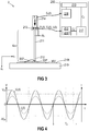
- Fig. 4 illustrates examples of the second transducer voltage V 2 (t) and the second transducer current I 2 (t).
- the second voltage V 2 (t) may be controlled to have (e.g. for each second ultrasonic frequency f 1 ) a desired signal shape (e.g. a sinus shape or any other, for instance periodical, shape), and the second current I 2 (t) may automatically adjust dependent on the electrical properties of the second ultrasonic transducer 213.
- a desired signal shape e.g. a sinus shape or any other, for instance periodical, shape
- first type bonding partners 301, 301' represent “first type bonding partners”
- second bonding partners 302, 302' represent “second type bonding partners”. It should be noted that any two first type bonding partners may have "the same properties" in a sense described above, and that any two second type bonding partners may have "the same properties" in a sense described above.
- a significant improvement as compared to the described unsatisfactory approach may be achieved by employing a second correction parameter k 2 that assists in employing the oscillation amplitude(s) of the first ultrasonic transducer 113 that has (have) been found to deliver a proper bonding result when bonding the first bonding partner 301 (i.e. a first type bonding partner) to the second bonding partner 302 (i.e. a second type bonding partner) using the first bonding machine 1 also as oscillation amplitude(s) of the second ultrasonic transducer 213 when bonding the first bonding partner 301' (i.e. a first type bonding partner) to the second bonding partner 302' (i.e.
- the first bonding machine 1 may also be referred to as "master machine”.
- the transducers 113, 213 are (mechanically) damped with the same damping (i.e. damped identically).
- the ultrasonic transducers 113, 213 are damped such that they experience the same mechanical damping.
- the ultrasonic transducers 113, 213 may be (mechanically) damped identically using the same damping device 400 or identically constructed damping devices 400. This will be explained in more detail further below.
- Fig. 5 illustrates the first bonding machine 1 of Fig. 1 operated in a calibration set-up in which the first ultrasonic transducer 113 it is damped by a first mechanical (calibration) damping.
- a damping device 400 is disposed on the surface 119t of the first support 119.
- the calibration force F cal may be constant (e.g. be controlled by the first control unit 110 or any other suitable control unit to a predetermined value).
- the first ultrasonic transducer 113 is, e.g. controlled by the first control unit 110 or any other suitable control unit, operated to oscillate in the first lateral direction x 1 at a first ultrasonic calibration frequency f cal1 .
- the first ultrasonic calibration frequency f cal1 may be, without being restricted to, a frequency from 20 kHz to 120 kHz.
- Operating the first ultrasonic transducer 113 to oscillate in the first lateral direction x 1 at the first ultrasonic calibration frequency f cal1 may include that the first control unit 110 (or another suitable control unit) causes the first power supply 115 to provide a first electrical calibration power P cal1 (t) as first electrical supply power P 1 (t), and, therefore, an average first electrical calibration power ⁇ P cal1 (t)> as average first electrical supply power ⁇ P 1 (t)> directly to the first ultrasonic transducer 113.
- the first electrical calibration power P cal1 (t) and, therefore, the average first electrical calibration power ⁇ P cal1 > are generated based on a first calibration control signal C cal1 which causes the first ultrasonic transducer 113, when it is damped by the first mechanical damping, to oscillate at a first calibration amplitude A cal1 .
- the first calibration control signal C cal1 may be directly provided to the first power supply 115 as first power supply input signal, e.g. when the first power correction unit 117 is omitted, or indirectly, e.g. via the first power correction unit 117 and a modified first calibration control signal C cal1 ' that is generated by the first power correction unit 117 based on the first calibration control signal C cal1 and that is provided to the first power supply 115 as first power supply input signal.
- Providing the first electrical calibration power P cal1 (t) as first electrical supply power P 1 (t) directly to the first ultrasonic transducer 113 includes providing an
- Fig. 6 illustrates the first electrical calibration voltage V cal1 (t) and the (alternating) first electrical calibration current I cal1 (t) as functions of the time t.
- the first power supply 115 may include a first control loop 116 (see Figures 1 and 5 ), e.g. a phase locked loop (PLL), causing the first alternating current I 1 (t) to be in phase with the first alternating voltage V 1 (t).
- PLL phase locked loop
- the first control loop 116 also causes the (alternating) first electrical calibration current I cal1 (t) to be in phase with the (alternating) first electrical calibration voltage V cal1 (t) which is illustrated in Fig. 6 .
- the first control loop 116 may optionally cause the first (alternating) transducer voltage V 1 (t) and the first (alternating) transducer current I 1 (t) to have their zero-crossings at identical or substantially identical instants of time. Therefore, the first control loop 116 may optionally cause the first (alternating) electrical calibration voltage V cal1 (t) and the first (alternating) calibration current I cal1 (t) to have their zero-crossings at identical or substantially identical instants of time which is also illustrated in Fig. 6 .
- the second bonding machine 2 of Fig. 3 may be, as illustrated in Fig. 7 , operated in a calibration set-up in which the second ultrasonic transducer 213 is damped by a second mechanical (calibration) damping which is identical to the first mechanical (calibration) damping of the first ultrasonic transducer 113.
- the damping device 400 used in the calibration setup of the first bonding machine 1 or an identically constructed damping device 400 is disposed on the surface 219t of the second support 219.
- the second ultrasonic calibration frequency f cal2 may be, without being restricted to, a frequency from 20 kHz to 120 kHz.
- the second ultrasonic calibration frequency f cal2 may be identical to the first ultrasonic calibration frequency f cal1 .
- Operating the second ultrasonic transducer 213 to oscillate in the second lateral direction x 2 at the second ultrasonic calibration frequency f cal2 may include that the second control unit 210 (or another suitable control unit) causes the second power supply 215 to provide a second electrical calibration power P cal2 (t) as second electrical supply power P 2 (t), and, therefore, an average second electrical calibration power ⁇ P cal2 (t)> as average second electrical supply power ⁇ P 2 (t)> directly to the second ultrasonic transducer 213.
- the second electrical calibration power P cal2 (t) and, therefore, the average second electrical calibration power ⁇ P cal2 > are generated based on a second calibration control signal C cal2 which causes the second ultrasonic transducer 213, when it is damped by the second mechanical damping, to oscillate at a second calibration amplitude A cal2 .
- the second calibration control signal C cal2 may be directly provided to the second power supply 215 as second power supply input signal, e.g. when the second power correction unit 217 is omitted, or indirectly, e.g. via the second power correction unit 217 and a modified second calibration control signal C cal2 ' that is generated by the second power correction unit 217 based on the second calibration control signal C cal2 and that is provided to the second power supply 215 as second power supply input signal.
- Fig. 8 illustrates the second electrical calibration voltage V cal2 (t) and the (alternating) second electrical calibration current I cal2 (t) as functions of the time t.
- the second power supply 215 may include a second control loop 216 (see Figures 3 and 6 ), e.g. a phase locked loop (PLL), causing the second alternating current I 2 (t) to be in phase with the second alternating voltage V 2 (t).
- PLL phase locked loop
- the second control loop 216 also causes the (alternating) second electrical calibration current I cal2 (t) to be in phase with the (alternating) second electrical calibration voltage V cal2 (t) which is illustrated in Fig. 8 .
- the second control loop 216 may optionally cause the second (alternating) transducer voltage V 2 (t) and the second (alternating) transducer current I 2 (t) to have their zero-crossings at identical or substantially identical instants of time. Therefore, the second control loop 216 may optionally cause the second (alternating) electrical calibration voltage V cal2 (t) and the second (alternating) calibration current I cal2 (t) to have their zero-crossings at identical or substantially identical instants of time which is also illustrated in Fig. 8 .
- Calibrating the second bonding machine 2 based on the first bonding machine 1 may take place based on a comparative measurement in which both the first ultrasonic transducer 113 and the second ultrasonic transducer 213 are mechanically damped identically and oscillate in a steady state.
- a first electrical calibration supply signal having a first electrical parameter and powering the first ultrasonic transducer 113 to oscillate as described above at a first calibration amplitude A cal1 is directly supplied to the first ultrasonic transducer 113
- a second electrical calibration supply having a second electrical parameter and powering the second ultrasonic transducer 213 to oscillate as described above at a second calibration amplitude A cal2 is directly supplied to the second ultrasonic transducer 213.
- the second electrical parameter is (e.g. by adjusting the second electrical calibration supply signal) adjusted such that the second calibration amplitude A cal2 is identical to the first calibration amplitude A cal1 .
- the first and second electrical parameters are used to calibrate the second bonding machine 2 based on the first bonding machine 1.
- the first electrical parameter and the second electrical parameter or a parameter or a function depending on and/or representing the first electrical parameter and the second electrical parameter may be stored in a memory of the second bonding machine 2, for instance in a memory of the second power correction unit 217.
- the stored first electrical parameter and the second electrical parameter or the stored parameter or function depending on and/or representing the first electrical parameter and the second electrical parameter may then be used to modify one, more than one or each second control signal C 2 based on the stored first and second electrical parameters, based on the stored parameter or based on the stored function.
- the first and second electrical parameters may be selected to be signals of identical type.
- the first electrical parameter may represent an amplitude V cal10 (see Fig. 6 ) of the first electrical calibration voltage V cal1 (t) and the second electrical parameter may represent an amplitude V cal20 (see Fig. 8 ) of the second electrical calibration voltage V cal2 (t).
- a parameter q2 represents a parameter q1 when the parameter q1 can be derived from the parameter q2.
- the parameter q1 can be derived from q1 itself, also q1 is considered as "parameter representing q1".
- V cal1 (t) and V cal2 (t) may be sinusoidal voltages.
- the (alternating) first electrical calibration voltage V cal1 (t) is directly applied to the first ultrasonic transducer 113 and causes an (alternating) first electrical calibration current I cal1 (t), e.g. a sinusoidal current, through the first ultrasonic transducer 113.
- I cal1 (t) e.g. a sinusoidal current
- the first ultrasonic transducer 113 oscillates in the first lateral direction x 1 as described above.
- the first ultrasonic transducer 113 has, in the first lateral direction x 1 , a first calibration amplitude A cal1 ( Fig. 5 ) and receives a first electrical calibration power P cal1 (t) having an average first electrical calibration power ⁇ P cal1 (t)>.
- the (alternating) second electrical calibration voltage V cal2 (t) is directly applied to the second ultrasonic transducer 213 and causes an (alternating) second electrical calibration current I cal2 (t), e.g. a sinusoidal current, through the second ultrasonic transducer 213.
- I cal2 (t) e.g. a sinusoidal current
- the second ultrasonic transducer 213 oscillates in the second lateral direction x 2 as described above.
- the second ultrasonic transducer 213 has, in the second lateral direction x 2 , a second calibration amplitude A cal2 ( Fig. 7 ) and receives a second electrical calibration power P cal2 (t) having an average second electrical calibration power ⁇ P cal2 (t)>.
- the average second electrical calibration power ⁇ P cal2 (t)> is adjusted such that the (steady-state) second calibration amplitude A cal2 is identical to the (steady-state) first calibration amplitude A cal1 .
- appropriately adjusting the average second electrical calibration power ⁇ P cal2 (t)> may take place by adjusting (regulating) the amplitude V cal20 (see Fig. 8 ) of the (e.g. sinusoidal) second electrical calibration voltage V cal2 (t).
- V cal20 see Fig. 8
- the first electrical parameter represents an amplitude V cal10 (see Fig. 6 ) of the (e.g. sinusoidal) first electrical calibration voltage V cal1 (t) and the second electrical parameter represents an amplitude V cal (see Fig. 8 ) of the (e.g. sinusoidal) second electrical calibration voltage V cal2 (t).
- the (alternating) first electrical calibration voltage V cal1 (t) is directly applied to the first ultrasonic transducer 113 and causes an (alternating) first electrical calibration current I cal1 (t), e.g. a sinusoidal current, through the first ultrasonic transducer 113.
- I cal1 (t) e.g. a sinusoidal current
- the first ultrasonic transducer 113 oscillates in the first lateral direction x 1 as described above.
- the first ultrasonic transducer 113 has, in the first lateral direction x 1 , a first calibration amplitude A cal1 ( Fig. 5 ).
- the (alternating) second electrical calibration voltage V cal2 (t) is directly applied to the second ultrasonic transducer 213 and causes an (alternating) second electrical calibration current I cal2 (t), e.g. a sinusoidal current, through the second ultrasonic transducer 213.
- I cal2 (t) e.g. a sinusoidal current
- the second ultrasonic transducer 213 oscillates in the second lateral direction x 2 as described above.
- the second ultrasonic transducer 213 has, in the second lateral direction x 2 , a second calibration amplitude A cal2 ( Fig. 7 ).
- the second electrical calibration voltage V cal2 (t) is adjusted such that the (steady-state) second calibration amplitude A cal2 is identical to the (steady-state) first calibration amplitude A cal1 .
- appropriately adjusting the second electrical calibration voltage V cal2 (t) may take place by adjusting (regulating) the amplitude V cal20 (see Fig. 8 ) of the (e.g. sinusoidal) second electrical calibration voltage V cal2 (t).
- V cal2 (t) e.g. sinusoidal
- methods for appropriately adjusting the second electrical calibration voltage V cal2 (t) are known in the art and thus not further explained herein.
- the (approximative) calibration of the second bonding machine 2, in particular for second control signals C 2 that differ from the calibration control signal C cal2 may take place based on the first and second electrical parameters of the first electrical calibration power P cal1 (t) and second electrical calibration power P cal2 (t), respectively.
- Approximately calibrating the second bonding machine 2 may include adapting the second bonding machine 2 such that it modifies a second control signal C 2 based on a first electrical parameter of the first electrical calibration supply P cal1 and on a second electrical parameter of the second electrical calibration supply P cal2 in order to generate a modified second control signal C 2 ', that it provides the modified second control signal C 2 ' to the second power supply 215 in order to cause the second power supply 215 to generate a second electrical supply power P 2 (t), and that it provides the second electrical supply power P 2 (t) to the second ultrasonic transducer 213.
- each second control signal C 2 the calibrated second bonding machine 2 will generate a corresponding modified second control signal C 2 '.
- Each modified second control signal C 2 ' that is provided to the input of the second power supply 215 causes the second power supply 215 to output a second electrical supply power P 2 (t) to the second ultrasonic transducer 213.
- the (unmodified) second control signal C 2 instead of the modified second control signal C 2 ' was provided to the input of the second power supply 215, the (unmodified) second control signal C 2 would cause the second power supply 215 to output an unmodified second electrical supply power P 2unmod (t) to the second ultrasonic transducer 213.
- feeding the modified second control signal C 2 ' instead of the (unmodified) second control signal C 2 to the input of the second power supply 215 causes the second power supply 215 to output a corresponding (modified) second electrical supply power P 2 (t) instead of the (unmodified) second electrical supply power P 2unmod (t) to the second ultrasonic transducer 213. Therefore, to each second control signal C 2 , a corresponding modified second control signal C 2 ', a corresponding (unmodified) second electrical supply power P 2unmod (t) and a corresponding (modified) second electrical supply power P 2 (t) are assigned.
- adapting the second bonding machine 2 such that it modifies the second control signal C 2 based on the first electrical parameter of the first electrical calibration supply P cal1 and on the second electrical parameter of the second electrical calibration supply P cal2 in order to generate the modified second control signal C 2 ' may take place by adapting the second bonding machine 2 such that it modifies the second control signal C 2 based on a difference ⁇ between the first electrical parameter of the first electrical calibration supply P cal1 and the second electrical parameter of the second electrical calibration supply P cal2 in order to generate the modified second control signal C 2 '.
- the second bonding machine 2 may be adapted to generate the modified second control signal C 2 ' such that a difference ⁇ between an electrical parameter of the unmodified second electrical supply power P 2unmod (t) and an electrical parameter of the second electrical supply power P 2 (t) is equal to the difference ⁇ between the first electrical parameter of the first electrical calibration supply P cal1 and the second electrical parameter of the second electrical calibration supply P cal2 .
- the electrical parameter of the unmodified second electrical supply power P 2unmod (t), the electrical parameter of the second electrical supply power P 2 (t), the first electrical parameter of the first electrical calibration supply P cal1 and the second electrical parameter of the second electrical calibration supply P cal2 may be of the same parameter type, e.g. an average power or an average voltage or a voltage amplitude or another parameter type.
- the electrical parameter of the unmodified second electrical supply power P 2unmod (t), the electrical parameter of the second electrical supply power P 2 (t), the first electrical parameter of the first electrical calibration supply P cal1 and the second electrical parameter of the second electrical calibration supply P cal2 are average powers of P 2unmod (t), P 2 (t), P cal1 and P cal2 , respectively.
- the electrical parameter of the unmodified second electrical supply power P 2unmod (t), the electrical parameter of the second electrical supply power P 2 (t), the first electrical parameter of the first electrical calibration supply P cal1 and the second electrical parameter of the second electrical calibration supply P cal2 are voltage amplitudes of the voltages generating, together with the related currents, the electrical powers P 2unmod (t), P 2 (t), P cal1 and P cal2 , respectively.
- the electrical parameter of the unmodified second electrical supply power P 2unmod (t), the electrical parameter of the second electrical supply power P 2 (t), the first electrical parameter of the first electrical calibration supply P cal1 and the second electrical parameter of the second electrical calibration supply P cal2 are average voltages of the voltages generating, together with the related currents, the electrical powers P 2unmod (t), P 2 (t), P cal1 and P cal2 , respectively.
- each of the electrical powers P 2unmod (t), P 2 (t), P cal1 and P cal2 is generated by an alternating voltage and an alternating current which are proportional to one another (so that they are in phase, have their zero crossings at identical instants of time and a constant, real-valued impedance of the respective first or second ultrasonic transducer 113, 213 as proportionality factor).
- the second bonding machine 2 may be adapted to generate for a number or for each of different second control signals C 2 a corresponding modified second control signal C 2 ' such that for each of the second control signals C 2 and the corresponding modified second control signal C 2 ' a difference ⁇ between an electrical parameter of the corresponding unmodified second electrical supply power P 2unmod (t) and an electrical parameter of the second electrical supply power P 2 (t) is the same and equal to the difference ⁇ between the first electrical parameter of the first electrical calibration supply P cal1 and the second electrical parameter of the second electrical calibration supply P cal2 .
- the first control signals C 1X may be provided by the first control unit 110 of the first bonding machine 1.
- the first control signals C 1X may also be provided to the first bonding machine 1 as external input signals.
- each of these first control signals C 1X may be, e.g.
- each second power signal P 2X (t) causes the second ultrasonic transducer 213 to oscillate at a corresponding second amplitude A 2X .
- a difference ⁇ between the first electrical parameter of the first electrical calibration supply P cal1 and the second electrical parameter of the second electrical calibration supply P cal2 may have been identified.
- the electrical parameter of the unmodified second electrical supply power P 2unmodX (t), the electrical parameter of the second electrical supply power P 2X (t), the first electrical parameter of the first electrical calibration supply P cal1 and the second electrical parameter of the second electrical calibration supply P cal2 may be of the same parameter type, e.g. an average power or an average voltage or a voltage amplitude or another parameter type.
- the average powers may be calculated according to equations (1) and (2).
- the average voltages may - exactly or approximately - be determined using any averaging method. For instance, a voltage to be averaged may pass a low pass filter that outputs the averaged voltage. Alternatively or additionally, a voltage V(t) to be averaged may be calculated based on a known shape (e.g. sinus shape) and a known amplitude, e.g.
- n 3 is a positive integer (i.e. n 3 ⁇ 1)
- t 3 is a point of time at which the averaging calculation starts
- T 3 is an oscillation period of the voltage V(t) to be averaged.
- the parameter n 3 may be elected to have a low value.
- n 3 may be, without being restricted to, elected from a range of 1 to 10 or 4 to 10.
- the ultrasonic transducers 113, 213 are (mechanically) damped identically using the same damping device 400 or identically constructed damping devices 400.
- a damping device 400 may be an elastic pad having, at a temperature of 23°C, a shore-hardness of more than 60 shore A (which approximately corresponds to 16 shore D), e.g. of more than 60 shore A and less than 100 shore A (which approximately corresponds to 58 shore D).
- Suitable materials are, without being restricted to, e.g., ethylene propylene diene monomer (EPDM) rubber, or a cellular material, e.g. nitrile butadiene rubber (NBR).
- a damping device 400 may be a semiconductor chip and the pressing force F cal may be greater than zero.
- a damping device 400 may be a damping clamp clamping the respective tool tip 112, 212.
- the pressing force F cal may be zero, or greater than zero.
- a damping device 400 may be a fluid (e.g. a liquid) into which the respective tool tip 112, 212 is immersed and the pressing force F cal is zero (i.e. there is no pressing force).
- a damping device 400 may directly act upon the transducer 113, 213, and the pressing force F cal may be zero or greater than zero.
- the damping device 400 may be an elastic pad that physically contacts the transducer 113, 213 and that may have, e.g., material properties mentioned with respect the first example.
- the damping device 400 may directly contact the bonding tool 111, 211 to which the transducer 113, 213 is mechanically coupled in a region close to the transducer 113, 213 but distant from the respective tool tip 112, 212.
- the damping device 400 may directly contact the bonding tool 111, 211 at a (center) distance from the respective tool tip 112, 212 that is equal to the (center) distance d1, d2 between the respective transducer 113, 213 and the tool tip 112, 212 of the respective bonding tool 111, 211.
- the damping device 400 may be, distant from the respective tool tip 112, 212 and close to the respective transducer 113, 213, pressed against the unit formed by the respective transducer 113, 213 and the respective bonding tool 111, 211 at a damping force F 400 parallel to the lateral direction x (i.e. the direction of the oscillation of the transducer 113, 213).
- At least one of the first calibration amplitude A cal1 of the first ultrasonic transducer 113 of the first bonding machine 1 and the second calibration amplitude A cal2 of the second ultrasonic transducer 213 of the second bonding machine 2 may be determined by laser vibrometry.
- a laser system 500 may be employed to determine the first calibration amplitude A cal1 of the first ultrasonic transducer 113 of the first bonding machine 1 using a laser beam 501 (see Fig. 5 ).
- the same or a different laser system 500 may be employed to determine the second calibration amplitude A cal2 of the second ultrasonic transducer 213 of the second bonding machine 2 using a laser beam 501 (see Fig.
- the first and second calibration amplitudes A cal1 , A cal2 may be determined directly at the respective ultrasonic transducer 113, 213 (i.e. the laser beam 501 is incident on the respective ultrasonic transducer 113, 213), or indirectly (e.g. when the laser beam 501 is incident on a point distant from the tool tip 112, 212 to which the respective ultrasonic transducer 113, 213 is mechanically coupled and close to the respective transducer 113, 213, on the bonding tool 111, 211.
- Fig. 13 illustrates, based on the examples explained above, a partial method 1000 for calibrating a second bonding machine 2 based on a calibrated first bonding machine 1.
- the first ultrasonic transducer 113 is oscillated by supplying a first electrical calibration voltage V cal1 (t) and a first electrical calibration current I cal1 (t) to the first ultrasonic transducer 113 (1002).
- the oscillating first ultrasonic transducer 113 is damped at a first damping (1004).
- a first electrical parameter is determined from the first calibration voltage V cal1 (t) and the first calibration current I cal1 (t), and a first oscillation amplitude A cal1 of the oscillating and damped first ultrasonic transducer 113 is determined (1006).
- the second ultrasonic transducer 213 is oscillated by supplying a second calibration voltage V cal2 (t) and a second calibration current I cal2 (t) to the second ultrasonic transducer 213 (1008).
- the oscillating second ultrasonic transducer 213 is damped at a second damping identical to the first damping (1010).
- a second electrical parameter at which the oscillating and damped second ultrasonic transducer 213 oscillates with a second oscillation amplitude A cal2 equal to the first oscillation amplitude A cal1 is determined (1012).
- the first electrical parameter and the second electrical parameter may be of the same parameter type, e.g. an average power or an average voltage or a voltage amplitude or another parameter type.
- a method 2000 for bonding first type bonding partners 301' to second type bonding partners 302' using the calibrated second bonding machine 2 will be explained. Initially, a second bonding machine 2 is calibrated based on a calibrated first bonding machine 1 (2002). The calibration may be performed as described above.
- first type bonding partners 301' are bonded to second type bonding partners 302' using the calibrated second bonding machine 2.
- a statistical process control may be performed (2004). If the SPC-Data are ok (i.e. the bonding results are acceptable), there is no need for recalibrating the second bonding machine 2, and the process of bonding first type bonding partners 301' to second type bonding partners 302' using the calibrated second bonding machine 2 may go on (2006, "YES"). However, if the SPC-Data are not ok (i.e.
- the second bonding machine 2 will be (re)calibrated based on the or another calibrated first bonding machine 1 (2002) and the described process may be repeated, and so on.
- first and second bonding partners have been described as constituent parts for forming electronic circuits. Nevertheless, the disclosed principles also apply for any other first and second bonding partners.
- the components of the first drive unit 100 have been described as individual constituents. However, any two or more of the components of the first drive unit 100 may be combined to form a single unit. Further, at least some of the components of the first drive unit 100 may be, at least in part, implemented in software. The same analogously applies for the components of the second drive unit 200. Moreover, all averages of signals (e.g. the first electrical power, the second electrical power, etc.) have been, for the sake of clearness, described as being calculated by averaging the respective signal over one or more complete oscillation period (e.g.
- each of these averages may be determined by any method known in the art.
- the average of the respective signal is not required to be formed based on one or more complete oscillation period (e.g. T 1 , T 2 ) of the respective signal.
- the average value of a signal may be a moving average.
- such a moving average may be derived by low-pass filtering the respective signal. It is also possible, to sample a signal to be averaged at predetermined instants of time and calculate the average value based on the acquired sample values.
Landscapes
- Engineering & Computer Science (AREA)
- Mechanical Engineering (AREA)
- Human Computer Interaction (AREA)
- Manufacturing & Machinery (AREA)
- Physics & Mathematics (AREA)
- General Physics & Mathematics (AREA)
- Automation & Control Theory (AREA)
- Wire Bonding (AREA)
Abstract
Description
- This disclosure in general relates to ultrasonic bonding techniques.
- Ultrasonic bonding techniques are widely employed to mechanically join two bonding partners. Thereby, a bonding tool oscillating at an ultrasonic frequency mechanically presses a second bonding partner with a pressing force against a first bonding partner. For example, the first bonding partner may be a semiconductor chip or an electronic circuit board and the second bonding partner may be a bonding wire. However, the quality of a joint between two bonding partners may depend on many parameters like the technical design of the bonding partners, the technical design of the bonding tool, the oscillation frequency of the bonding tool, the pressing force, etc. For example, bonding bonding wires of different types (e.g. different materials, different diameters/cross-sections) to a particular type of semiconductor chip may require different production parameters (e.g. oscillation frequency, pressing force) in order to achieve reliable joints. Therefore, each particular combination of a first and second type bonding partner may require extensive experiments (e.g. test series varying the pressing force and the oscillation frequency) in order to find proper production parameters.
- Nevertheless, using one or more control signals found to deliver suitable bonding results for joining the bonding partners of a particular combination of a first and second type bonding partner using a first bonding machine may be inappropriate when employed to join bonding partners of identical type using a different bonding machine. In other words, optimizing the quality of identical joints produced with different bonding machines may require repeating the above-mentioned extensive experiments for each of the employed bonding machines. Hence, there is a need for improved solutions.
- One aspect relates to a method for calibrating a second bonding machine based on a calibrated first bonding machine. The first bonding machine includes a first ultrasonic transducer, the second bonding machine includes a second ultrasonic and a power supply. The method includes: damping the first ultrasonic transducer by a first mechanical damping; providing a first electrical calibration supply to the first ultrasonic transducer, the first electrical calibration supply causing the first ultrasonic transducer, when it is damped by the first mechanical damping, to oscillate at a first calibration amplitude; providing a second electrical calibration supply to the second ultrasonic transducer, wherein the second electrical calibration supply is configured to cause the second ultrasonic transducer, when it is damped by a second mechanical damping identical to the first mechanical damping, to oscillate at a second calibration amplitude identical to the first calibration amplitude. The second bonding machine is adapted to modify a second control signal based on a first electrical parameter of the first electrical calibration supply and on a second electrical parameter of the second electrical calibration supply, in order to generate a modified second control signal; provide the modified second control signal to the power supply in order to cause the power supply to generate a second electrical supply; and provide the second electrical supply to the second ultrasonic transducer.
- The invention can be better understood with reference to the following description and drawings. The components in the figures are not necessarily to scale, emphasis instead being placed upon illustrating the principles of the invention. Moreover, in the figures, like reference numerals designate corresponding parts. In the present description and the claims, some elements are designated as "first element", "second element", "third element", etc. It should be pointed out that designations like "first", "second", "third", etc. are not intended to be enumerative but solely serve to identify individual "elements". That is, e.g., the existence of a "third element" does not require the presence of a "first element" and a "second element".
-
-
Figure 1 illustrates a normal operation of a first bonding machine. -
Figure 2 illustrates a first transducer voltage and a first transducer current output by a power supply of the first bonding machine directly to an ultrasonic transducer of the first bonding machine. -
Figure 3 illustrates a normal operation of a second bonding machine. -
Figure 4 illustrates a second transducer voltage and a second transducer current output by a power supply of the second bonding machine directly to an ultrasonic transducer of the second bonding machine. -
Figure 5 illustrates a calibration operation of the first bonding machine ofFig. 1 . -
Figure 6 illustrates a first calibration voltage directly applied to a first ultrasonic transducer of the first bonding machine ofFig. 1 and the resulting first alternating current. -
Figure 7 illustrates a calibration operation of the second bonding machine ofFig. 3 . -
Figure 8 illustrates a second calibration voltage directly applied to a second ultrasonic transducer of the second bonding machine ofFig. 3 and the resulting second alternating current. -
Figure 9(a) illustrates the behavior of the calibrated second bonding machine ofFig. 3 when a modified second control signal is provided to the input of the power supply of the ultrasonic transducer of the second bonding machine. -
Figure 9(b) illustrates the behavior of the second bonding machine ofFig. 3 when the unmodified second control signal instead of the modified second control signal is provided to the input of the power supply of the ultrasonic transducer of the second bonding machine. -
Figure 10 illustrates an example in which an oscillating ultrasonic transducer mechanically coupled to a bonding tool is indirectly damped using a clamp clamping a tool tip of the bonding tool. -
Figure 11 illustrates an example in which an oscillating ultrasonic transducer mechanically coupled to a bonding tool is indirectly damped by immersing a tool tip of the bonding tool into a fluid. -
Figure 12 illustrates an example in which an oscillating ultrasonic transducer mechanically coupled to a bonding tool is directly damped using an elastic pad affecting the transducer. -
Figure 13 illustrates a partial method for calibrating a second bonding machine based on a calibrated first bonding machine. - Figure 14 illustrates a method for bonding first type bonding partners to second type bonding partners using statistical process control
- In the following detailed description, reference is made to the accompanying drawings. The drawings show specific examples in which the invention may be practiced. It is to be understood that the features and principles described with respect to the various examples may be combined with each other, unless specifically noted otherwise.
-
Fig. 1 schematically illustrates afirst bonding machine 1. Thefirst bonding machine 1 includes afirst bonding tool 111, a (e.g. piezoelectric or magnetostrictive) firstultrasonic transducer 113, a firstpressing device 114, afirst support 119 and afirst drive unit 100. Thefirst drive unit 100 includes afirst control unit 110, afirst power supply 115, a firstpower correction unit 117 and a firstpressing device driver 118. Controlled by thefirst control unit 110, thefirst power supply 115 generates a first electrical supply power P1(t) that is directly provided to the firstultrasonic transducer 113. In order to cause thefirst power supply 115 to generate the first electrical supply power P1(t), thefirst control unit 110 generates and outputs a first control signal C1, and thefirst power supply 115 generates the first electrical supply power P1(t) based on the first control signal C1. - According to the illustrated embodiment, the first control signal C1 may be provided to the first
power correction unit 117 which generates, based on the first control signal C1, a modified first control signal C1' that is provided to thefirst power supply 115 as a first power supply input signal. The firstpower correction unit 117 is optional and may implement a calibration of thefirst bonding machine 1. Thefirst power supply 115 generates the first electrical supply power P1(t) based on the first power supply input signal, i.e., in the illustrated embodiment, based on the modified first control signal C1' which is supplied to the input of thefirst power supply 115. Therefore, thefirst power supply 115 generates the first electrical supply power P1(t) also based on the first control signal C1. That is, the first electrical supply power P1(t) may change depending on the first control signal C1. - As already explained above, the first
power correction unit 117 is optional. According to one embodiment (not illustrated), the firstpower correction unit 117 may be omitted and the first control signal C1 may be directly provided to the input of thefirst power supply 115 as the first power supply input signal. Also in this embodiment, thefirst power supply 115 generates the first electrical supply power P1(t) based on the first control signal C1. - The first electrical power P1(t) causes the first
ultrasonic transducer 113 to oscillate at a first ultrasonic frequency f1 in a first lateral direction x1. InFig. 1 , a double arrow schematically illustrates the direction of the oscillation, and a dashed line schematically illustrates the region of oscillation of the oscillating firstultrasonic transducer 113. The firstultrasonic transducer 113 is mechanically coupled to thefirst bonding tool 111 so that thefirst bonding tool 111 is forced to oscillate at the oscillation frequency (i.e. the first ultrasonic frequency f1) of the firstultrasonic transducer 113.Fig. 1 , in which the firstultrasonic transducer 113 is depicted in its neutral position of oscillation, also illustrates the first oscillation amplitude A1 of the firstultrasonic transducer 113 in the first lateral direction x1. - During normal operation of the
first bonding machine 1, i.e. when thefirst bonding machine 1 is forming a bonded connection between afirst bonding partner 301 and asecond bonding partner 302, thefirst bonding partner 301 is (directly or indirectly) placed on and fixed (e.g. clamped, sucked, adhered, etc.) to afirst surface 119t of thefirst support 119. The second bonding partner 302 (i.e. at least a section of the second bonding partner 302) is, e.g. subsequently, placed between afirst tool tip 112 of thefirst bonding tool 111 and thefirst bonding partner 301 and pressed against thefirst bonding partner 301 by thefirst tool tip 112 with a first pressing force F1. Thereby, thesecond bonding partner 302 physically contacts thefirst bonding partner 301. According to the provided example and without being restricted to it, thefirst bonding partner 301 may be a semiconductor chip and thesecond bonding partner 302 may be a bonding wire. Optionally, thefirst bonding partner 301 may be, prior to being placed on thesurface 119t of thesupport 119, pre-mounted (e.g. soldered or sintered or adhered) on a carrier 303 (e.g. a metal plate, a circuit board, a metallized ceramic substrate or any other kind of carrier) and then, together with thecarrier 303, placed on thefirst surface 119t so that thecarrier 303 is arranged between thefirst surface 119t and thefirst bonding partner 301. - With the first pressing force F1 applied, the first
ultrasonic transducer 113 starts oscillating in the first lateral direction x1 at the first ultrasonic frequency f1 and forces thefirst bonding tool 111 and particularly thefirst tool tip 112 to also oscillate at the first oscillation frequency f1 in the first lateral direction x1. Thereby, energy is transferred into the interface region between the first andsecond bonding partners second bonding partners - In order to drive the first
pressing device 114, thefirst control unit 110 may provide a first pressing device control signal S1(t) to the firstpressing device 114 in order to cause the firstpressing device 114 to provide a desired first pressing force F1). That is, the first pressing force F1 is generated by the firstpressing device 114 based on the first pressing device control signal S1(t), applied to thefirst bonding tool 111, and transferred by thefirst bonding tool 111 to thefirst tool tip 112 which is spaced distant from the first ultrasonic transducer at a first distance d111. The direction z1 of the first pressing force F1 (which may also be referred to as first pressing direction or as first vertical direction z1) may be perpendicular or substantially perpendicular to the first lateral direction x1. The first pressing force F1 may be changed or, alternatively, kept constant during the bonding process. Alternatively or additionally, the first oscillation frequency f1 may be changed or, alternatively, kept constant during the bonding process. - The
first drive unit 100 serves to drive at least the firstultrasonic transducer 113 and, optionally, also the firstpressing device 114. In order to drive the firstultrasonic transducer 113, thefirst control unit 110 may be designed to generate (e.g. to set and/or to regulate) the first electrical power P1(t) output by thefirst power supply 115 based on the first control signal C1, and in order to control the firstpressing device 114, thefirst control unit 110 may be designed to adjust (e.g. to set and/or to regulate) the pressing force F1 produced by the firstpressing device driver 118 and the firstpressing device 114 downstream thereof. - The first electrical power P1(t) results from a first transducer voltage V1(t) and a first transducer current I1(t) both output by the
first power supply 115 directly to the firstultrasonic transducer 113. Therefore, the first voltage V1(t) and the first current I1(t) may also be referred to as first transducer voltage V1(t) and first transducer current I1(t) respectively. That is, the first electrical power P1(t) may be calculated according to P1(t) = V1(t)·I1(t).Fig. 2 illustrates examples of the first transducer voltage V1(t) and the first transducer current I1(t). According to one example, the first voltage V1(t) may be controlled to have a desired signal shape (e.g. a sinus shape or any other, for instance periodical, shape), and the first current I1(t) may automatically adjust dependent on the electrical properties of the firstultrasonic transducer 113. - Optionally, the
first power supply 115 may include afirst control loop 116, e.g. a phase locked loop (PLL), causing the first (alternating) current I1(t) to be in phase with the first (alternating) transducer voltage V1(t). Also optionally, thefirst control loop 116 may cause the first (alternating) transducer voltage V1(t) and the first (alternating) transducer current I1(t) to have their zero-crossings at identical or substantially identical instants of time so that (in the steady state, i.e. when the first oscillation period T1, which is the reciprocal of the first ultrasonic frequency f1, is constant) no or no substantial reactive power occurs. - As can be seen from an example of a sinusoidal first transducer voltage V1(t), the first electrical power P1(t) is, at least at the zero-crossings of the first transducer voltage V1(t), equal to zero. Hence, for a sinusoidal first transducer voltage V1(t) (or any other first transducer voltage V1(t) periodically assuming zero volts) the resulting first electrical power P1(t) periodically assumes zero at a high repetition frequency of at least twice the first ultrasonic frequency f1. A person skilled in the art will appreciate, that for a practical bonding process, in which a bonded connection between a
first bonding partner 301 and asecond bonding partner 302 is formed, an average first electrical power <P1> may be more informative than (permanently changing) instantaneous values of the first electrical power P1(t). On the other hand, it may be desirable to vary the average first electrical power <P1> during the bonding process. Therefore, considering an average first electrical power <P1> of the first electrical power P1(t) (in the description and the claims briefly also referred to as "average first electrical power <P1>") may be useful. The average first electrical power <P1> = <P1(V1, I1)> may be calculated as follows:
second bonding partner 302 and afirst bonding partner 301, the average first electrical power <P1> and the first ultrasonic frequency f1 (and, therefore, the first oscillation period T1) may change, during the related bonding process, over time. It should also be noted that the first transducer voltage V1(t) and the first transducer current I1(t) may be sinusoidal or not. -
Fig. 3 schematically illustrates asecond bonding machine 2 when forming a bonded connection between a first bonding partner 301' and a second bonding partner 302'. With regard to the bonded connection to be formed, the first bonding partner 301' as a whole or at least at its region to be bonded to the second bonding partner 302', may have the same properties as thefirst bonding partner 301 described with reference toFig. 1 and the second bonding partner 302' as a whole or at least at its region to be bonded to the first bonding partner 301', may have the same properties as thesecond bonding partner 302 described with reference toFig. 1 . As used herein, "the same properties" may include "structurally identical", "of identical construction", "identical", "substantially identical", etc. - Except for the fact that the second
power correction unit 217 is not omitted, the construction and the functional principle of thesecond bonding machine 2 may be the same as the construction and the functional principle of thefirst bonding machine 1 described with reference toFig. 1 . Therefore, the description of the construction and the functional principle of thefirst bonding machine 1 analogously applies for thesecond bonding machine 2. In order to differentiate between the elements (100, 111... 119, 119t) of or related to thefirst bonding machine 1 and the elements (200, 211...219, 219t) of or related to thesecond bonding machine 2, a particular element of or related to thefirst bonding machine 1 is denoted as "first" element and identified using a three-digital reference numeral having a leading "1", and an element of or related to thesecond bonding machine 2 which corresponds to the particular element is denoted as "second" element and identified using the same reference numeral as the particular element but with the leading "1" replaced by a leading "2". That is, a first element of thefirst bonding machine 1 inFig. 1 identified with a reference numeral 1xy corresponds to a second element of thesecond bonding machine 2 inFig. 3 identified with a reference numeral 2xy. In other words, the description of the construction and the functional principle of thesecond bonding machine 2 may be derived from the description of the construction and the functional principle of thefirst bonding machine 1 by replacing each "first element 1xy" of or related to thefirst bonding machine 1 by a corresponding "second element 2xy" of or related to thesecond bonding machine 2. Further, the elements, signals, factors etc. related to thefirst bonding machine 1 are to be replaced by the corresponding elements, signals, factors etc. related to thesecond bonding machine 2 according to the following table:element, signal, factor etc. related to first bonding machine 1corresponding element, signal, factor etc. related to second bonding machine 2first pressing force F1 second pressing force F2 first lateral direction x1 second lateral direction x2 first vertical direction z1 second lateral direction z2 first pressing force control signal S1(t) second pressing force control signal S2(t) first control signal C1 second control signal C2 modified first control signal C1' modified second control signal C2' first oscillation amplitude A1 second oscillation amplitude A2 first oscillation period T1 second oscillation period T2 first ultrasonic frequency f1 second ultrasonic frequency f2 first distance d111 second distance d211 first electrical (transducer) voltage V1(t) second electrical (transducer) voltage V2(t) first electrical (transducer) current I1(t) second electrical (transducer) current I2(t) first electrical supply power P1(t) second electrical supply power P2(t) average first el. power <P1> average second el. power <P2> positive integer n1 positive integer n2 point of time t1 point of time t2 first bonding partner 301first bonding partner 301' second bonding partner 302second bonding partner 302' carrier 303carrier 303' - Finally, equation (1) is to be replaced by equation (2):

- The second electrical power P2(t) results from a second transducer voltage V2(t) and a second transducer current I2(t) both output by the
second power supply 215 directly to the secondultrasonic transducer 213. Therefore, the second voltage V2(t) and the second current I2(t) may also be referred to as second transducer voltage V2(t) and second transducer current I2(t) respectively. That is, the second electrical power P2(t) may be calculated according to P2(t) = V2(t)·I2(t).Fig. 4 illustrates examples of the second transducer voltage V2(t) and the second transducer current I2(t). According to one example, the second voltage V2(t) may be controlled to have (e.g. for each second ultrasonic frequency f1) a desired signal shape (e.g. a sinus shape or any other, for instance periodical, shape), and the second current I2(t) may automatically adjust dependent on the electrical properties of the secondultrasonic transducer 213. - As initially described, finding proper production parameters for a particular combination of a first type bonding partner and a second type bonding partner may require extensive experiments. In the examples of
Figures 1 and3 , thefirst bonding partners 301, 301' represent "first type bonding partners" and thesecond bonding partners 302, 302' represent "second type bonding partners". It should be noted that any two first type bonding partners may have "the same properties" in a sense described above, and that any two second type bonding partners may have "the same properties" in a sense described above. Provided that proper production parameters for bonding a secondtype bonding partner 302 to a firsttype bonding partner 301 using thefirst bonding machine 1 have been found (typically requiring extensive experiments), it is desirable to transfer the found proper production parameters to thesecond bonding machine 2 when bonding the second type bonding partner 302' (i.e. a bonding partner of the same type as thesecond bonding partner 302 ofFig. 1 ) to a first type bonding partner 301' (i.e. to a bonding partner of the same type as thefirst bonding partner 301 ofFig. 1 ) using thesecond bonding machine 2. - At first glance, doing so appears to be easy, involving simply employing a
second bonding machine 2 that is identical in construction to thefirst bonding machine 1 and driving the secondultrasonic transducer 213 and the secondpressing device 214 with thesecond control unit 210 of thesecond bonding machine 2 using control signals (e.g. V2(t), I2(t), S2(t)) which are identical to the corresponding control signals (e.g. V1(t), I1(t), S1(t)) used by thefirst control unit 110 of thefirst bonding machine 1 for driving the firstultrasonic transducer 113 and the firstpressing device 114. However, it turns out that this approach may still lead to an undesirably varying quality of the produced bond connections. - As found by the inventors of the present invention, the mentioned undesirably varying quality may be caused by a spread throughout assumedly identical first and second
ultrasonic transducers power correction unit 117 is omitted or when C1'=C1) and a second control signal C2 identical to the first control signal C1 as the second power supply input signal of the second power supply 215 (i.e. when the secondpower correction unit 217 would be omitted or when C2'=C2), the first and secondultrasonic transducers second boning machine 2 based on a well-testedfirst bonding machine 1 would be desirable. - According to one aspect, a significant improvement as compared to the described unsatisfactory approach may be achieved by employing a second correction parameter k2 that assists in employing the oscillation amplitude(s) of the first
ultrasonic transducer 113 that has (have) been found to deliver a proper bonding result when bonding the first bonding partner 301 (i.e. a first type bonding partner) to the second bonding partner 302 (i.e. a second type bonding partner) using thefirst bonding machine 1 also as oscillation amplitude(s) of the secondultrasonic transducer 213 when bonding the first bonding partner 301' (i.e. a first type bonding partner) to the second bonding partner 302' (i.e. a second type bonding partner) using thesecond bonding machine 2. This is realized by calibrating thesecond bonding machine 2 based on a second correction parameter k2 that is determined by comparing the operation of thefirst bonding machine 1 and the operation of thesecond bonding machine 2 under identical conditions. Therefore, thefirst bonding machine 1 may also be referred to as "master machine". In order to perform the calibration, thetransducers ultrasonic transducers ultrasonic transducers device 400 or identically constructed dampingdevices 400. This will be explained in more detail further below. -
Fig. 5 illustrates thefirst bonding machine 1 ofFig. 1 operated in a calibration set-up in which the firstultrasonic transducer 113 it is damped by a first mechanical (calibration) damping. In the example ofFig. 5 , a dampingdevice 400 is disposed on thesurface 119t of thefirst support 119. Thefirst tool tip 112 is, via the firstpressing device 114 and, e.g., controlled by thefirst control unit 110 or any other suitable control unit, pressed against the dampingdevice 400 with a calibration force Fcal (i.e. F1(t) = Fcal). The calibration force Fcal may be constant (e.g. be controlled by thefirst control unit 110 or any other suitable control unit to a predetermined value). Simultaneously, the firstultrasonic transducer 113 is, e.g. controlled by thefirst control unit 110 or any other suitable control unit, operated to oscillate in the first lateral direction x1 at a first ultrasonic calibration frequency fcal1. The first ultrasonic calibration frequency fcal1 may be, without being restricted to, a frequency from 20 kHz to 120 kHz. - Operating the first
ultrasonic transducer 113 to oscillate in the first lateral direction x1 at the first ultrasonic calibration frequency fcal1 may include that the first control unit 110 (or another suitable control unit) causes thefirst power supply 115 to provide a first electrical calibration power Pcal1(t) as first electrical supply power P1(t), and, therefore, an average first electrical calibration power <Pcal1(t)> as average first electrical supply power <P1(t)> directly to the firstultrasonic transducer 113. The first electrical calibration power Pcal1(t) and, therefore, the average first electrical calibration power <Pcal1> are generated based on a first calibration control signal Ccal1 which causes the firstultrasonic transducer 113, when it is damped by the first mechanical damping, to oscillate at a first calibration amplitude Acal1. For this, the first calibration control signal Ccal1 may be directly provided to thefirst power supply 115 as first power supply input signal, e.g. when the firstpower correction unit 117 is omitted, or indirectly, e.g. via the firstpower correction unit 117 and a modified first calibration control signal Ccal1' that is generated by the firstpower correction unit 117 based on the first calibration control signal Ccal1 and that is provided to thefirst power supply 115 as first power supply input signal. - Providing the first electrical calibration power Pcal1(t) as first electrical supply power P1(t) directly to the first
ultrasonic transducer 113 includes providing an - (alternating) first electrical calibration voltage Vcal1(t) and an (alternating) first electrical calibration current Ical1(t) directly to the first
ultrasonic transducer 113 so that P1(t) = Vcal1(t)·Ical1(t). The average first electrical calibration power <Pcal1(Vcal1(t)·Tcal1(t))> (briefly also referred to as <Pcal1>) may be calculated according to equation (1) by <Pcal1> = <P1(Vcal1, Ical1)>. -
Fig. 6 illustrates the first electrical calibration voltage Vcal1(t) and the (alternating) first electrical calibration current Ical1(t) as functions of the time t. The period T1 of the first electrical calibration voltage Vcal1(t) and of the first electrical calibration current Ical1(t) is the reciprocal of the first ultrasonic calibration frequency fcal1 (i.e. T1 = 1/fcal1). As already described above, thefirst power supply 115 may include a first control loop 116 (seeFigures 1 and5 ), e.g. a phase locked loop (PLL), causing the first alternating current I1(t) to be in phase with the first alternating voltage V1(t). Therefore, thefirst control loop 116 also causes the (alternating) first electrical calibration current Ical1(t) to be in phase with the (alternating) first electrical calibration voltage Vcal1(t) which is illustrated inFig. 6 . As also mentioned above, thefirst control loop 116 may optionally cause the first (alternating) transducer voltage V1(t) and the first (alternating) transducer current I1(t) to have their zero-crossings at identical or substantially identical instants of time. Therefore, thefirst control loop 116 may optionally cause the first (alternating) electrical calibration voltage Vcal1(t) and the first (alternating) calibration current Ical1(t) to have their zero-crossings at identical or substantially identical instants of time which is also illustrated inFig. 6 . - Analogously, the
second bonding machine 2 ofFig. 3 may be, as illustrated inFig. 7 , operated in a calibration set-up in which the secondultrasonic transducer 213 is damped by a second mechanical (calibration) damping which is identical to the first mechanical (calibration) damping of the firstultrasonic transducer 113. In the example ofFig. 6 , the dampingdevice 400 used in the calibration setup of thefirst bonding machine 1 or an identically constructed dampingdevice 400 is disposed on thesurface 219t of thesecond support 219. Thesecond tool tip 212 is, via the secondpressing device 214 and, e.g., controlled by thesecond control unit 210 or any other suitable control unit, pressed against the dampingdevice 400 with a calibration force Fcal identical to the calibration force Fcal used in the calibration setup of the first bonding machine 1 (i.e. F2(t) = Fcal). Therefore, the calibration force Fcal used in the calibration setup of thesecond bonding machine 2 may also be constant (e.g. be controlled by thesecond control unit 210 or any other suitable control unit to the predetermined value of Fcal). Simultaneously, the secondultrasonic transducer 213 is, e.g. controlled by thesecond control unit 210 or any other suitable control unit, operated to oscillate in a second lateral direction x2 at a second ultrasonic calibration frequency fcal2. The second ultrasonic calibration frequency fcal2 may be, without being restricted to, a frequency from 20 kHz to 120 kHz. Optionally, the second ultrasonic calibration frequency fcal2 may be identical to the first ultrasonic calibration frequency fcal1. - Operating the second
ultrasonic transducer 213 to oscillate in the second lateral direction x2 at the second ultrasonic calibration frequency fcal2 may include that the second control unit 210 (or another suitable control unit) causes thesecond power supply 215 to provide a second electrical calibration power Pcal2(t) as second electrical supply power P2(t), and, therefore, an average second electrical calibration power <Pcal2(t)> as average second electrical supply power <P2(t)> directly to the secondultrasonic transducer 213. The second electrical calibration power Pcal2(t) and, therefore, the average second electrical calibration power <Pcal2> are generated based on a second calibration control signal Ccal2 which causes the secondultrasonic transducer 213, when it is damped by the second mechanical damping, to oscillate at a second calibration amplitude Acal2. For this, the second calibration control signal Ccal2 may be directly provided to thesecond power supply 215 as second power supply input signal, e.g. when the secondpower correction unit 217 is omitted, or indirectly, e.g. via the secondpower correction unit 217 and a modified second calibration control signal Ccal2' that is generated by the secondpower correction unit 217 based on the second calibration control signal Ccal2 and that is provided to thesecond power supply 215 as second power supply input signal. - Providing the second electrical calibration power Pcal2(t) as second electrical supply power P2(t) directly to the second
ultrasonic transducer 213 includes providing an (alternating) second electrical calibration voltage Vcal2(t) and an (alternating) second electrical calibration current Ical2(t) directly to the secondultrasonic transducer 213 so that P2(t) = Vcal2(t)'Ical2(t). The average second electrical calibration power <Pcal2(Vcal2(t)·Ical2(t))> (briefly also referred to as <Pcal2>) may be calculated according to equation (2) by <Pcal2> = <P2(Vcal2(t), Ical2(t))>. -
Fig. 8 illustrates the second electrical calibration voltage Vcal2(t) and the (alternating) second electrical calibration current Ical2(t) as functions of the time t. The period T2 of the second electrical calibration voltage Vcal2(t) and of the second electrical calibration current Ical2(t) is the reciprocal of the second ultrasonic calibration frequency fcal2 (i.e. T2 = 1/fcal2). As already described above, thesecond power supply 215 may include a second control loop 216 (seeFigures 3 and6 ), e.g. a phase locked loop (PLL), causing the second alternating current I2(t) to be in phase with the second alternating voltage V2(t). Therefore, thesecond control loop 216 also causes the (alternating) second electrical calibration current Ical2(t) to be in phase with the (alternating) second electrical calibration voltage Vcal2(t) which is illustrated inFig. 8 . As also mentioned above, thesecond control loop 216 may optionally cause the second (alternating) transducer voltage V2(t) and the second (alternating) transducer current I2(t) to have their zero-crossings at identical or substantially identical instants of time. Therefore, thesecond control loop 216 may optionally cause the second (alternating) electrical calibration voltage Vcal2(t) and the second (alternating) calibration current Ical2(t) to have their zero-crossings at identical or substantially identical instants of time which is also illustrated inFig. 8 . - Calibrating the
second bonding machine 2 based on thefirst bonding machine 1 may take place based on a comparative measurement in which both the firstultrasonic transducer 113 and the secondultrasonic transducer 213 are mechanically damped identically and oscillate in a steady state. A first electrical calibration supply signal having a first electrical parameter and powering the firstultrasonic transducer 113 to oscillate as described above at a first calibration amplitude Acal1 is directly supplied to the firstultrasonic transducer 113, and a second electrical calibration supply having a second electrical parameter and powering the secondultrasonic transducer 213 to oscillate as described above at a second calibration amplitude Acal2 is directly supplied to the secondultrasonic transducer 213. Thereby, the second electrical parameter is (e.g. by adjusting the second electrical calibration supply signal) adjusted such that the second calibration amplitude Acal2 is identical to the first calibration amplitude Acal1. The first and second electrical parameters are used to calibrate thesecond bonding machine 2 based on thefirst bonding machine 1. For this, the first electrical parameter and the second electrical parameter or a parameter or a function depending on and/or representing the first electrical parameter and the second electrical parameter may be stored in a memory of thesecond bonding machine 2, for instance in a memory of the secondpower correction unit 217. The stored first electrical parameter and the second electrical parameter or the stored parameter or function depending on and/or representing the first electrical parameter and the second electrical parameter may then be used to modify one, more than one or each second control signal C2 based on the stored first and second electrical parameters, based on the stored parameter or based on the stored function. - The first and second electrical parameters may be selected to be signals of identical type. According to a first example, the first electrical parameter may represent an average first electrical power <Pcal1> = <P1(Vcal1(t), Ical1(t))> according to equation (1) and the second electrical parameter may represent an average second electrical power <Pcal2> = <P2(Vcal2(t), Ical2(t))> according to equation (2). According to a second example, the first electrical parameter may represent an amplitude Vcal10 (see
Fig. 6 ) of the first electrical calibration voltage Vcal1(t) and the second electrical parameter may represent an amplitude Vcal20 (seeFig. 8 ) of the second electrical calibration voltage Vcal2(t). Thereby, the first and second electrical calibration voltages Vcal1(t) and Vcal2(t) may have the same basic form (e.g. a sinusoidal) so that Vcal2(t) = C·Vcal1(t+Δt12), wherein C is a constant and wherein Δt12 is a constant that may also assume zero. - As used herein, a parameter q2 represents a parameter q1 when the parameter q1 can be derived from the parameter q2. For instance, the amplitude VSIN0 of a sinusoidal voltage VSIN(t) can be calculated from the RMS (root mean square) value VRMS of the sinusoidal voltage VSIN(t) by

- A first example of a possible calibration process of the
second bonding machine 2 based on thefirst bonding machine 1 will now be explained based on the above-mentioned example in which the first electrical parameter represents an average first electrical power <Pcal1> = <P1(Vcal1(t), Ical1(t))> according to equation (1) and the second electrical parameter represents an average second electrical power <Pcal2> = <P2(Vcal2(t), Ical2(t))> according to equation (2). As illustrated inFigures 6 and8 , Vcal1(t) and Vcal2(t) may be sinusoidal voltages. - The (alternating) first electrical calibration voltage Vcal1(t) is directly applied to the first
ultrasonic transducer 113 and causes an (alternating) first electrical calibration current Ical1(t), e.g. a sinusoidal current, through the firstultrasonic transducer 113. As a result, the firstultrasonic transducer 113 oscillates in the first lateral direction x1 as described above. In the steady state, the firstultrasonic transducer 113 has, in the first lateral direction x1, a first calibration amplitude Acal1 (Fig. 5 ) and receives a first electrical calibration power Pcal1(t) having an average first electrical calibration power <Pcal1(t)>. Analogously, the (alternating) second electrical calibration voltage Vcal2(t) is directly applied to the secondultrasonic transducer 213 and causes an (alternating) second electrical calibration current Ical2(t), e.g. a sinusoidal current, through the secondultrasonic transducer 213. As a result, the secondultrasonic transducer 213 oscillates in the second lateral direction x2 as described above. In the steady state, the secondultrasonic transducer 213 has, in the second lateral direction x2, a second calibration amplitude Acal2 (Fig. 7 ) and receives a second electrical calibration power Pcal2(t) having an average second electrical calibration power <Pcal2(t)>. Thereby, the average second electrical calibration power <Pcal2(t)> is adjusted such that the (steady-state) second calibration amplitude Acal2 is identical to the (steady-state) first calibration amplitude Acal1. - For instance, appropriately adjusting the average second electrical calibration power <Pcal2(t)> may take place by adjusting (regulating) the amplitude Vcal20 (see
Fig. 8 ) of the (e.g. sinusoidal) second electrical calibration voltage Vcal2(t). Generally, methods for appropriately adjusting the average second electrical calibration power <Pcal2(t)> are known in the art and thus not further explained herein. - A second example of a possible calibration process of the
second bonding machine 2 based on thefirst bonding machine 1 will now be explained based on the above-mentioned example in which the first electrical parameter represents an amplitude Vcal10 (seeFig. 6 ) of the (e.g. sinusoidal) first electrical calibration voltage Vcal1(t) and the second electrical parameter represents an amplitude Vcal (seeFig. 8 ) of the (e.g. sinusoidal) second electrical calibration voltage Vcal2(t). - The (alternating) first electrical calibration voltage Vcal1(t) is directly applied to the first
ultrasonic transducer 113 and causes an (alternating) first electrical calibration current Ical1(t), e.g. a sinusoidal current, through the firstultrasonic transducer 113. As a result, the firstultrasonic transducer 113 oscillates in the first lateral direction x1 as described above. In the steady state, the firstultrasonic transducer 113 has, in the first lateral direction x1, a first calibration amplitude Acal1 (Fig. 5 ). Analogously, the (alternating) second electrical calibration voltage Vcal2(t) is directly applied to the secondultrasonic transducer 213 and causes an (alternating) second electrical calibration current Ical2(t), e.g. a sinusoidal current, through the secondultrasonic transducer 213. As a result, the secondultrasonic transducer 213 oscillates in the second lateral direction x2 as described above. In the steady state, the secondultrasonic transducer 213 has, in the second lateral direction x2, a second calibration amplitude Acal2 (Fig. 7 ). Thereby, the second electrical calibration voltage Vcal2(t) is adjusted such that the (steady-state) second calibration amplitude Acal2 is identical to the (steady-state) first calibration amplitude Acal1. - For instance, appropriately adjusting the second electrical calibration voltage Vcal2(t) may take place by adjusting (regulating) the amplitude Vcal20 (see
Fig. 8 ) of the (e.g. sinusoidal) second electrical calibration voltage Vcal2(t). Generally, methods for appropriately adjusting the second electrical calibration voltage Vcal2(t) are known in the art and thus not further explained herein. - Summarizing the above, the knowledge resulting from the calibration process is that for a particular mechanical damping which is identical for the first and second
ultrasonic transducers ultrasonic transducer 113 with the first electrical calibration power Pcal1(t) and powering the secondultrasonic transducer 213 with the second electrical calibration power Pcal2(t) leads to identical calibration amplitudes of theultrasonic transducers second bonding machine 2, in particular for second control signals C2 that differ from the calibration control signal Ccal2, may take place based on the first and second electrical parameters of the first electrical calibration power Pcal1(t) and second electrical calibration power Pcal2(t), respectively. - Approximately calibrating the
second bonding machine 2 may include adapting thesecond bonding machine 2 such that it modifies a second control signal C2 based on a first electrical parameter of the first electrical calibration supply Pcal1 and on a second electrical parameter of the second electrical calibration supply Pcal2 in order to generate a modified second control signal C2', that it provides the modified second control signal C2' to thesecond power supply 215 in order to cause thesecond power supply 215 to generate a second electrical supply power P2(t), and that it provides the second electrical supply power P2(t) to the secondultrasonic transducer 213. - For one, more than one or each second control signal C2, the calibrated
second bonding machine 2 will generate a corresponding modified second control signal C2'. Each modified second control signal C2' that is provided to the input of thesecond power supply 215 causes thesecond power supply 215 to output a second electrical supply power P2(t) to the secondultrasonic transducer 213. However, if the (unmodified) second control signal C2 instead of the modified second control signal C2' was provided to the input of thesecond power supply 215, the (unmodified) second control signal C2 would cause thesecond power supply 215 to output an unmodified second electrical supply power P2unmod(t) to the secondultrasonic transducer 213. In other words, feeding the modified second control signal C2' instead of the (unmodified) second control signal C2 to the input of thesecond power supply 215 causes thesecond power supply 215 to output a corresponding (modified) second electrical supply power P2(t) instead of the (unmodified) second electrical supply power P2unmod(t) to the secondultrasonic transducer 213. Therefore, to each second control signal C2, a corresponding modified second control signal C2', a corresponding (unmodified) second electrical supply power P2unmod(t) and a corresponding (modified) second electrical supply power P2(t) are assigned. - According to one embodiment, adapting the
second bonding machine 2 such that it modifies the second control signal C2 based on the first electrical parameter of the first electrical calibration supply Pcal1 and on the second electrical parameter of the second electrical calibration supply Pcal2 in order to generate the modified second control signal C2' may take place by adapting thesecond bonding machine 2 such that it modifies the second control signal C2 based on a difference Δ between the first electrical parameter of the first electrical calibration supply Pcal1 and the second electrical parameter of the second electrical calibration supply Pcal2 in order to generate the modified second control signal C2'. - For instance, the
second bonding machine 2 may be adapted to generate the modified second control signal C2' such that a difference Δ between an electrical parameter of the unmodified second electrical supply power P2unmod(t) and an electrical parameter of the second electrical supply power P2(t) is equal to the difference Δ between the first electrical parameter of the first electrical calibration supply Pcal1 and the second electrical parameter of the second electrical calibration supply Pcal2. Thereby, the electrical parameter of the unmodified second electrical supply power P2unmod(t), the electrical parameter of the second electrical supply power P2(t), the first electrical parameter of the first electrical calibration supply Pcal1 and the second electrical parameter of the second electrical calibration supply Pcal2 may be of the same parameter type, e.g. an average power or an average voltage or a voltage amplitude or another parameter type. - For instance, if the parameter type is an average power, the electrical parameter of the unmodified second electrical supply power P2unmod(t), the electrical parameter of the second electrical supply power P2(t), the first electrical parameter of the first electrical calibration supply Pcal1 and the second electrical parameter of the second electrical calibration supply Pcal2 are average powers of P2unmod(t), P2(t), Pcal1 and Pcal2, respectively. Or, if the parameter type is a voltage amplitude, the electrical parameter of the unmodified second electrical supply power P2unmod(t), the electrical parameter of the second electrical supply power P2(t), the first electrical parameter of the first electrical calibration supply Pcal1 and the second electrical parameter of the second electrical calibration supply Pcal2 are voltage amplitudes of the voltages generating, together with the related currents, the electrical powers P2unmod(t), P2(t), Pcal1 and Pcal2, respectively. Or, if the parameter type is an average voltage, the electrical parameter of the unmodified second electrical supply power P2unmod(t), the electrical parameter of the second electrical supply power P2(t), the first electrical parameter of the first electrical calibration supply Pcal1 and the second electrical parameter of the second electrical calibration supply Pcal2 are average voltages of the voltages generating, together with the related currents, the electrical powers P2unmod(t), P2(t), Pcal1 and Pcal2, respectively.
- Using a voltage amplitude or an average voltage as parameter type is of particular interest if each of the electrical powers P2unmod(t), P2(t), Pcal1 and Pcal2 is generated by an alternating voltage and an alternating current which are proportional to one another (so that they are in phase, have their zero crossings at identical instants of time and a constant, real-valued impedance of the respective first or second
ultrasonic transducer - According to one example, the
second bonding machine 2 may be adapted to generate for a number or for each of different second control signals C2 a corresponding modified second control signal C2' such that for each of the second control signals C2 and the corresponding modified second control signal C2' a difference Δ between an electrical parameter of the corresponding unmodified second electrical supply power P2unmod(t) and an electrical parameter of the second electrical supply power P2(t) is the same and equal to the difference Δ between the first electrical parameter of the first electrical calibration supply Pcal1 and the second electrical parameter of the second electrical calibration supply Pcal2. - For instance, it is assumed that there is a number of pairwise distinct first control signals C1X (X = A, B, C, ...) each of which causing, when used as first control signal C1 (i.e. C1 = C1X, see
Fig. 1 ), a corresponding first amplitude A1 = A1X of the firstultrasonic transducer 113. For example, the first control signals C1X may be provided by thefirst control unit 110 of thefirst bonding machine 1. The first control signals C1X may also be provided to thefirst bonding machine 1 as external input signals. In order to define a desired bonding profile, each of these first control signals C1X may be, e.g. subsequently and directly provided to the input of thefirst power supply 115 and cause thefirst power supply 115 to output a corresponding electrical power to the firstultrasonic transducer 113. In turn, the corresponding electrical power output to the firstultrasonic transducer 113 may cause the firstultrasonic transducer 113 to oscillate at a corresponding first amplitude A1 = A1X (X = A, B, C, ...). - Apparently, it is advantageous if the same pairwise distinct first control signals C1X (X = A, B, C, ...) cause, when used as second control signals C2X (X = A, B, C, ...) for the second bonding machine 2 (i.e. C2 = C2X, see
Fig. 3 ), corresponding second amplitudes A2 = A2X (X = A, B, C, ...) of the secondultrasonic transducer 213 which are substantially identical to the corresponding first amplitudes A1X. In other words, even though the first and secondultrasonic transducers second bonding machine 2 such that each first control signal C1X causing a corresponding first amplitude A1X of the firstultrasonic transducer 113 causes, when used as second control signal C2X, a corresponding second amplitude A2X of the secondultrasonic transducer 213 which is identical or approximately identical to A1X (i.e. C2X = C1X causes A2X to be identical or approximately identical to A1X; X = A, B, C,...). - The related calibration process will now be explained in more detail with reference to
Fig. 9 . According toFig. 9(a) , each of the second control signals C2X (X = A, B, C, ...) is provided to and modified by the secondpower correction unit 217 in order to obtain a corresponding modified second control signal C2X' (X = A, B, C, ...) which when provided to the input of thesecond power supply 215 causes thesecond power supply 215 to output a corresponding second power signal P2X(t) to the secondultrasonic transducer 213. In turn, each second power signal P2X(t) causes the secondultrasonic transducer 213 to oscillate at a corresponding second amplitude A2X. InFig. 9(b) it is illustrated that the unmodified second control signals C2X (X = A, B, C, ...) would, when provided to the input of thesecond power supply 215, cause thesecond power supply 215 to output corresponding unmodified second power signals P2unmodX(t) to the secondultrasonic transducer 213. - As described above, a difference Δ between the first electrical parameter of the first electrical calibration supply Pcal1 and the second electrical parameter of the second electrical calibration supply Pcal2 may have been identified. This same difference Δ is used to modify each of the second control signals C2X (X = A, B, C, ...) by the second power correction unit 217 (
Fig. 9(a) ) such that the difference Δ between an electrical parameter of the unmodified second electrical supply power P2unmodX(t) and an electrical parameter of the second electrical supply power P2X(t) is equal to the difference Δ. Thereby, the electrical parameter of the unmodified second electrical supply power P2unmodX(t), the electrical parameter of the second electrical supply power P2X(t), the first electrical parameter of the first electrical calibration supply Pcal1 and the second electrical parameter of the second electrical calibration supply Pcal2 may be of the same parameter type, e.g. an average power or an average voltage or a voltage amplitude or another parameter type. - The second electrical supply power P2X(t) is a product of a corresponding second electrical supply voltage V2X(t) and a corresponding second electrical supply current I2X(t), i.e. P2X(t) = V2X(t)·I2X(t) (X = A, B, C,...). Accordingly, the unmodified second electrical supply power P2unmodX(t) is a product of a corresponding unmodified second electrical supply voltage V2unmodX(t) and a corresponding unmodified second electrical supply current I2unmodX(t), i.e. P2unmodX(t) = V2unmodX(t)·I2unmodX(t) (X = A, B, C,...).
- If the parameter type is an average power, the second control signals C2X may be modified to corresponding modified second control signals C2X' such that <P2unmodX(t)> - <P2X(t)> = <Pcal1(t)> - <Pcal2(t)> = Δ = constant (X = A, B, C,...). For instance, the average powers may be calculated according to equations (1) and (2).
- If the parameter type is an voltage amplitude, the second control signals C2X may be modified to corresponding modified second control signals C2X' such that V2unmodX0 - V2X0 = Vcal10 - Vcal20 = Δ = constant, wherein V2unmodX0 is the voltage amplitude of V2unmodA(t) and V2X0 is the voltage amplitude of V2x(t) (X = A, B, C,...).
- If the parameter type is an average voltage, the second control signals C2X may be modified to corresponding modified second control signals C2X such that <V2unmodX(t)> - <V2X(t)> = <Vcal1(t)> - <Vcal2(t)> = Δ = constant (X = A, B, C,...). The average voltages may - exactly or approximately - be determined using any averaging method. For instance, a voltage to be averaged may pass a low pass filter that outputs the averaged voltage. Alternatively or additionally, a voltage V(t) to be averaged may be calculated based on a known shape (e.g. sinus shape) and a known amplitude, e.g. by

- In the calibration process described above, the
ultrasonic transducers device 400 or identically constructed dampingdevices 400. - According to a first example, a damping
device 400 may be an elastic pad having, at a temperature of 23°C, a shore-hardness of more than 60 shore A (which approximately corresponds to 16 shore D), e.g. of more than 60 shore A and less than 100 shore A (which approximately corresponds to 58 shore D). Suitable materials are, without being restricted to, e.g., ethylene propylene diene monomer (EPDM) rubber, or a cellular material, e.g. nitrile butadiene rubber (NBR). - According to a second example, a damping
device 400 may be a semiconductor chip and the pressing force Fcal may be greater than zero. - According to a third example illustrated in
Fig. 10 , a dampingdevice 400 may be a damping clamp clamping therespective tool tip - According to a fourth example illustrated in
Fig. 11 , a dampingdevice 400 may be a fluid (e.g. a liquid) into which therespective tool tip - According to a fifth example illustrated in
Fig. 12 , a dampingdevice 400 may directly act upon thetransducer device 400 may be an elastic pad that physically contacts thetransducer device 400 may directly contact thebonding tool transducer transducer respective tool tip device 400 may directly contact thebonding tool respective tool tip respective transducer tool tip respective bonding tool device 400 may be, distant from therespective tool tip respective transducer respective transducer respective bonding tool transducer 113, 213). - In each of the above examples, at least one of the first calibration amplitude Acal1 of the first
ultrasonic transducer 113 of thefirst bonding machine 1 and the second calibration amplitude Acal2 of the secondultrasonic transducer 213 of thesecond bonding machine 2 may be determined by laser vibrometry. For instance, alaser system 500 may be employed to determine the first calibration amplitude Acal1 of the firstultrasonic transducer 113 of thefirst bonding machine 1 using a laser beam 501 (seeFig. 5 ). Accordingly, the same or adifferent laser system 500 may be employed to determine the second calibration amplitude Acal2 of the secondultrasonic transducer 213 of thesecond bonding machine 2 using a laser beam 501 (seeFig. 6 ). As illustrated inFigures 5 and 6 , the first and second calibration amplitudes Acal1, Acal2 may be determined directly at the respectiveultrasonic transducer 113, 213 (i.e. thelaser beam 501 is incident on the respectiveultrasonic transducer 113, 213), or indirectly (e.g. when thelaser beam 501 is incident on a point distant from thetool tip ultrasonic transducer respective transducer bonding tool -
Fig. 13 illustrates, based on the examples explained above, apartial method 1000 for calibrating asecond bonding machine 2 based on a calibratedfirst bonding machine 1. In thatmethod 1000, the firstultrasonic transducer 113 is oscillated by supplying a first electrical calibration voltage Vcal1(t) and a first electrical calibration current Ical1(t) to the first ultrasonic transducer 113 (1002). - The oscillating first
ultrasonic transducer 113 is damped at a first damping (1004). A first electrical parameter is determined from the first calibration voltage Vcal1(t) and the first calibration current Ical1(t), and a first oscillation amplitude Acal1 of the oscillating and damped firstultrasonic transducer 113 is determined (1006). The secondultrasonic transducer 213 is oscillated by supplying a second calibration voltage Vcal2(t) and a second calibration current Ical2(t) to the second ultrasonic transducer 213 (1008). The oscillating secondultrasonic transducer 213 is damped at a second damping identical to the first damping (1010). From the second calibration voltage Vcal2(t) and the second calibration current Ical2(t), a second electrical parameter at which the oscillating and damped secondultrasonic transducer 213 oscillates with a second oscillation amplitude Acal2 equal to the first oscillation amplitude Acal1, is determined (1012). Thereby, the first electrical parameter and the second electrical parameter may be of the same parameter type, e.g. an average power or an average voltage or a voltage amplitude or another parameter type. - Referring to Fig. 14, a
method 2000 for bonding first type bonding partners 301' to second type bonding partners 302' using the calibratedsecond bonding machine 2 will be explained. Initially, asecond bonding machine 2 is calibrated based on a calibrated first bonding machine 1 (2002). The calibration may be performed as described above. - Subsequently, first type bonding partners 301' are bonded to second type bonding partners 302' using the calibrated
second bonding machine 2. Thereby, a statistical process control (SPC) may be performed (2004). If the SPC-Data are ok (i.e. the bonding results are acceptable), there is no need for recalibrating thesecond bonding machine 2, and the process of bonding first type bonding partners 301' to second type bonding partners 302' using the calibratedsecond bonding machine 2 may go on (2006, "YES"). However, if the SPC-Data are not ok (i.e. the bonding results are inacceptable or are acceptable but expected to become inacceptable) (2006, "NO"), thesecond bonding machine 2 will be (re)calibrated based on the or another calibrated first bonding machine 1 (2002) and the described process may be repeated, and so on. - In the above-explained methods and modifications, the first and second bonding partners have been described as constituent parts for forming electronic circuits. Nevertheless, the disclosed principles also apply for any other first and second bonding partners.
- In the examples described above, the components of the first drive unit 100 (e.g. the
first control unit 110, thefirst power supply 115, the firstpower correction unit 117 and the first pressing device driver 118) have been described as individual constituents. However, any two or more of the components of thefirst drive unit 100 may be combined to form a single unit. Further, at least some of the components of thefirst drive unit 100 may be, at least in part, implemented in software. The same analogously applies for the components of thesecond drive unit 200. Moreover, all averages of signals (e.g. the first electrical power, the second electrical power, etc.) have been, for the sake of clearness, described as being calculated by averaging the respective signal over one or more complete oscillation period (e.g. T1, T2) of the respective signal. However, each of these averages may be determined by any method known in the art. Thereby, the average of the respective signal is not required to be formed based on one or more complete oscillation period (e.g. T1, T2) of the respective signal. For instance, the average value of a signal may be a moving average. For instance, such a moving average may be derived by low-pass filtering the respective signal. It is also possible, to sample a signal to be averaged at predetermined instants of time and calculate the average value based on the acquired sample values.
Claims (15)
- A method for calibrating a second bonding machine (2) based on a calibrated first bonding machine (1), the first bonding machine (1) comprising a first ultrasonic transducer (113), the second bonding machine (2) comprising a second ultrasonic transducer (213) and a power supply (215), the method comprising:damping the first ultrasonic transducer (113) by a first mechanical damping;providing a first electrical calibration supply (Pcaii(t), Vcaii(t)) to the first ultrasonic transducer (113), the first electrical calibration supply (Pcal1(t), Vcal1(t)) causing the first ultrasonic transducer (113), when it is damped by the first mechanical damping, to oscillate at a first calibration amplitude (Acal1);providing a second electrical calibration supply (Pcal2(t), Vcal2(t)) to the second ultrasonic transducer (213), wherein the second electrical calibration supply (Pcal2(t), Vcal2(t)) is configured to cause the second ultrasonic transducer (213), when it is damped by a second mechanical damping identical to the first mechanical damping, to oscillate at a second calibration amplitude (Acal2) identical to the first calibration amplitude (Acal1); andadapting the second bonding machine (2) to:modify a second control signal (C2, C2X) based on a first electrical parameter of the first electrical calibration supply (Pcal1(t), Vcal1(t)) and on a second electrical parameter of the second electrical calibration supply (Pcal2(t), Vcal2(t)) in order to generate a modified second control signal (C2', C2X');provide the modified second control signal (C2', C2X') to the power supply (215) in order to cause the power supply (215) to generate a second electrical supply (P2(t), V2(t)); andprovide the second electrical supply (P2(t), V2(t)) to the second ultrasonic transducer (213).
- The method as claimed in claim 1, wherein:(a) the first electrical parameter is an average (<Pcal1(t)>) of an electrical power (Pcal1(t)) of the first electrical calibration supply (Pcal1(t), Vcal1(t)) and the second electrical parameter is an average (<Pcal2(t)>) of an electrical power (Pcal2(t)) of the second electrical calibration supply (Pcal2(t), Vcal1(t)); or(b) the first electrical parameter is an average (<Vcal1(t)>) of a first voltage (Vcal1(t)) of the first electrical calibration supply (Pcal1(t), Vcal1(t)) and the second electrical parameter is an average (<Vcal2(t)>) of a second voltage (Vcal2(t)) of the second electrical calibration supply (Pcal2(t), Vcal1(t)); or(c) the first electrical parameter is a first amplitude (Vcal10) of a first voltage (Vcal1(t)) of the first electrical calibration supply (Pcal1(t),Vcal1(t)) and the second electrical parameter is a second amplitude (Vcal20) of a second voltage (Vcal2(t)) of the second electrical calibration supply (Pcal2(t) ,Vcal2(t)).
- The method as claimed in any of the preceding claims, wherein modifying the second control signal (C2, C2X) based on the first electrical parameter of the first electrical calibration supply (Pcal1(t), Vcal1(t)) and the second electrical parameter of the second electrical calibration supply (Pcal2(t), Vcal2(t)) in order to generate the modified second control signal (C2', C2X') comprises modifying the second control signal (C2, C2X) based on a difference between the first electrical parameter of the first electrical calibration supply (Pcal1(t), Vcal1(t)) and the second electrical parameter of the second electrical calibration supply (Pcal2(t), Vcal2(t)).
- The method as claimed in claim 3, wherein the second bonding machine (2) is adapted to generate the modified second control signal (C2', C2X') such that a difference between- an electrical parameter of an unmodified second electrical power (P2unmod(t), P2unmodX(t)) the power supply (215) would output to the second ultrasonic transducer (213) if the second control signal (C2, C2X) instead of the modified second control signal (C2', C2X') was provided to the power supply (215) and- an electrical parameter of the second electrical supply (P2(t), V2(t)) is equal to the difference between- the first electrical parameter of the first electrical calibration supply (Pcal1(t), Vcal1(t)) and- the second electrical parameter of the second electrical calibration supply (Pcal2(t), Vcal2(t)).
- The method as claimed in any of the preceding claims, wherein:adapting the second bonding machine (2) to provide the second electrical supply (P2(t), V2(t)) to the second ultrasonic transducer (213) includesadapting the second bonding machine (2) to provide a second alternating voltage (V2(t)) and a second alternating current (I2(t)) to the second ultrasonic transducer (213), the second alternating current (I2(t)) being in phase with the second alternating voltage (V2(t)).
- The method as claimed in claim 5, wherein:the second alternating voltage (V2(t)) and the second alternating current (I2(t)) comprise zero crossings at common instants of time.
- The method as claimed in any of the preceding claims, wherein:the first bonding machine (1) comprises a first tool tip (112) distant from the first ultrasonic transducer (113);the second bonding machine (2) comprises a second tool tip (212) distant from the second ultrasonic transducer (213);damping the oscillating first ultrasonic transducer (113) comprises mechanically damping the oscillating first ultrasonic transducer (113) at the first tool tip (112); anddamping the oscillating second ultrasonic transducer (213) comprises mechanically damping the oscillating second ultrasonic transducer (213) at the second tool tip (212).
- The method as claimed in claim 7, wherein:damping the oscillating first ultrasonic transducer (113) at the first tool tip (112) and damping the oscillating second ultrasonic transducer (213) at the second tool tip (212) comprises one of:pressing the first tool tip (112) with a first pressing force (F1) against a first elastic pad and pressing the second tool tip (212) with a second pressing force (F2) identical to the first pressing force (F1) against the first elastic pad or against a second elastic pad identically constructed as the first elastic pad;pressing the first tool tip (112) with a first pressing force (F1) against a first semiconductor chip and pressing the second tool tip (212) with a second pressing force (F2) identical to the first pressing force (F1) against the first semiconductor chip or against a second semiconductor chip identically constructed as the first semiconductor chip;clamping the first tool tip (112) using a first clamp and clamping the second tool tip (212) using the first clamp or a second clamp identically constructed as the first clamp; andimmersing the first tool tip (112) into a first fluid and immersing the second tool tip (212) into the first fluid or into a second fluid identical to the first fluid.
- The method as claimed in claim 8, wherein the first elastic pad comprises, at a temperature of 23°C, a hardness of more than 60 shore-A or of more than 16 shore-D.
- The method as claimed in any of claims 1 to 6, wherein damping the oscillating first ultrasonic transducer (113) comprises:pressing a first damping element (400) directly against the first ultrasonic transducer (113) or, at a same first distance (d1) from a first tool tip (112) of the first bonding machine (1) as the first ultrasonic transducer (113), against the first bonding tool (111); andpressing the first damping element (400) or a second damping element (400) identical to the first damping element (400) directly against the second ultrasonic transducer (213) or, at a same second distance (d2) from a second tool tip (212) of the second bonding machine (2) as the second ultrasonic transducer (213), against the second bonding tool (211).
- The method as claimed in any of the preceding claims comprising:adapting the second bonding machine (2) tostore the first electrical parameter and the second electrical parameter or a parameter or a function depending on the first electrical parameter and the second electrical parameter in a memory of the second bonding machine (2); andmodify the second control signal (C2, C2X) based on the stored first and second electrical parameters, based on the stored parameter or based on the stored function.
- The method as claimed in any of the preceding claims, wherein:providing the first electrical calibration supply (Pcal1(t), Vcal1(t)) to the first ultrasonic transducer (113) comprises applying a first calibration voltage (Vcal1(t)) to the first ultrasonic transducer (113), the first calibration voltage (Vcal1(t)) causing a first calibration current (Ical1(t)) through the first ultrasonic transducer (113);providing the second electrical calibration supply (Pcal2(t), Vcal2(t)) to the second ultrasonic transducer (213) comprises applying a second calibration voltage (Vcal2(t)) to the second ultrasonic transducer (213), the second calibration voltage (Vcal2(t)) causing a second calibration current (Ical2(t)) through the second ultrasonic transducer (213);the first calibration voltage (Vcal1(t)) and the first calibration current (Ical1(t)) are in phase and comprise common zero-crossings; andthe second calibration voltage (Vcal2(t)) and the second calibration current (Ical2(t)) are in phase and comprise common zero-crossings.
- The method as claimed in claim 12, wherein
the first calibration voltage (Vcal1(t)) comprises a first fundamental frequency (fcal1) in a range from 20 kHz to 120 kHz; and
the second calibration voltage (Vcal2(t)) comprises a second fundamental frequency (fcal2) in a range from 20 kHz to 120 kHz. - The method as claimed in any of the preceding claims wherein
the first electrical calibration supply (Pcal1(t), Vcal1(t)) is generated based on a first calibration control signal (Ccal1);
the second electrical calibration supply (Pcal2(t), Vcal2(t)) is generated based on a second calibration control signal (Ccal2) identical to the first calibration control signal (Ccal1). - The method as claimed in claim 14, wherein the second control signal (C2, C2X) is different from the second calibration control signal (Ccal2).
Priority Applications (3)
| Application Number | Priority Date | Filing Date | Title |
|---|---|---|---|
| EP18186443.0A EP3603826B1 (en) | 2018-07-31 | 2018-07-31 | Method for calibrating an ultrasonic bonding machine |
| CN201910693605.6A CN110773409B (en) | 2018-07-31 | 2019-07-30 | Method for calibrating an ultrasonic bonder |
| US16/527,289 US11646291B2 (en) | 2018-07-31 | 2019-07-31 | Method for calibrating an ultrasonic bonding machine |
Applications Claiming Priority (1)
| Application Number | Priority Date | Filing Date | Title |
|---|---|---|---|
| EP18186443.0A EP3603826B1 (en) | 2018-07-31 | 2018-07-31 | Method for calibrating an ultrasonic bonding machine |
Publications (2)
| Publication Number | Publication Date |
|---|---|
| EP3603826A1 true EP3603826A1 (en) | 2020-02-05 |
| EP3603826B1 EP3603826B1 (en) | 2023-05-10 |
Family
ID=63293902
Family Applications (1)
| Application Number | Title | Priority Date | Filing Date |
|---|---|---|---|
| EP18186443.0A Active EP3603826B1 (en) | 2018-07-31 | 2018-07-31 | Method for calibrating an ultrasonic bonding machine |
Country Status (3)
| Country | Link |
|---|---|
| US (1) | US11646291B2 (en) |
| EP (1) | EP3603826B1 (en) |
| CN (1) | CN110773409B (en) |
Families Citing this family (4)
| Publication number | Priority date | Publication date | Assignee | Title |
|---|---|---|---|---|
| US12235302B2 (en) * | 2020-12-16 | 2025-02-25 | Kulicke And Soffa Industries, Inc. | Methods of detecting connection issues between a wire bonding tool and an ultrasonic transducer of a wire bonding machine |
| KR102818141B1 (en) * | 2021-06-07 | 2025-06-11 | 가부시키가이샤 신가와 | Method for manufacturing semiconductor devices and wire bonding device |
| DE102022117799A1 (en) * | 2022-07-15 | 2024-01-18 | Herrmann Ultraschalltechnik Gmbh & Co. Kg | Ultrasonic vibration unit with hard decoupling element |
| CN119965124B (en) * | 2025-01-13 | 2025-10-28 | 深圳市德沃先进自动化有限公司 | Parameter compensation method, device, equipment and storage medium for wire bonding |
Citations (3)
| Publication number | Priority date | Publication date | Assignee | Title |
|---|---|---|---|---|
| EP1897648A1 (en) * | 2006-09-05 | 2008-03-12 | Technische Universität Berlin | Method and device for controlling the generation of ultrasonic wire bonds |
| US20110056267A1 (en) * | 2007-12-21 | 2011-03-10 | Kulicke And Soffa Industries, Inc. | Method of calibrating a constant voltage supply for an ultrasonic transducer of a wire bonding machine |
| US20140209663A1 (en) * | 2013-01-25 | 2014-07-31 | Keng Yew Song | Wire bonder and method of calibrating a wire bonder |
Family Cites Families (39)
| Publication number | Priority date | Publication date | Assignee | Title |
|---|---|---|---|---|
| US4696425A (en) * | 1984-07-17 | 1987-09-29 | Texas Instruments Incorporated | Programmable ultrasonic power supply |
| JPH0258845A (en) * | 1988-08-25 | 1990-02-28 | Toshiba Corp | Ultrasonic wire bonder |
| JPH0777229B2 (en) * | 1988-10-28 | 1995-08-16 | 株式会社新川 | Ultrasonic wire bonding equipment |
| JPH088285B2 (en) * | 1990-02-23 | 1996-01-29 | 株式会社東芝 | Wire bonding method |
| EP0498936B1 (en) * | 1991-02-15 | 1995-01-25 | Esec Sa | Process and device for energy transducer oscillation amplitude measurement |
| JP3007195B2 (en) * | 1991-09-18 | 2000-02-07 | 株式会社日立製作所 | Bonding equipment and bonding part inspection equipment |
| JP2705423B2 (en) * | 1992-01-24 | 1998-01-28 | 株式会社日立製作所 | Ultrasonic bonding equipment and quality monitoring method |
| JP3128710B2 (en) * | 1992-08-12 | 2001-01-29 | 株式会社新川 | Wire bonding method |
| US5357423A (en) * | 1993-02-22 | 1994-10-18 | Kulicke And Soffa Investments, Inc. | Apparatus and method for automatically adjusting power output of an ultrasonic generator |
| US5326015A (en) * | 1993-03-29 | 1994-07-05 | Kulicke And Soffa Investments, Inc. | Wire bonder tail length monitor |
| US5446403A (en) * | 1994-02-04 | 1995-08-29 | Zenith Data Systems Corporation | Power on reset signal circuit with clock inhibit and delayed reset |
| US5816476A (en) * | 1994-08-24 | 1998-10-06 | Verity Instruments Inc. | Dual frequency power supply and transducer |
| US5578888A (en) * | 1994-12-05 | 1996-11-26 | Kulicke And Soffa Investments, Inc. | Multi resonance unibody ultrasonic transducer |
| US5944249A (en) * | 1996-12-12 | 1999-08-31 | Texas Instruments Incorporated | Wire bonding capillary with bracing component |
| JP3566166B2 (en) * | 2000-02-10 | 2004-09-15 | 株式会社新川 | Tool position measuring method, offset measuring method, reference member and bonding device |
| TW521358B (en) * | 2000-09-22 | 2003-02-21 | Asm Tech Singapore Pte Ltd | A method of bonding wires |
| US6616030B2 (en) * | 2001-05-07 | 2003-09-09 | West Bond, Inc. | Gantry mounted ultrasonic wire bonder with orbital bonding tool head |
| KR20030066344A (en) * | 2002-02-01 | 2003-08-09 | 에섹 트레이딩 에스에이 | Method for determining optimum bond parameters when bonding with a wire bonder |
| KR20030066348A (en) * | 2002-02-01 | 2003-08-09 | 에섹 트레이딩 에스에이 | Method for the calibration of a wire bonder |
| US7481351B2 (en) * | 2003-12-23 | 2009-01-27 | Samsung Electronics Co., Ltd. | Wire bonding apparatus and method for clamping a wire |
| US7845542B2 (en) * | 2005-09-22 | 2010-12-07 | Palomar Technologies, Inc. | Monitoring deformation and time to logically constrain a bonding process |
| CH700015B1 (en) * | 2007-04-04 | 2010-06-15 | Oerlikon Assembly Equipment Ag | Ultrasonic Transducer. |
| KR100950977B1 (en) * | 2007-10-18 | 2010-04-01 | (주)창조엔지니어링 | Ultrasonic wave welding machine of lateral vibration type and ultrasonic bonding device |
| CN102047400B (en) * | 2008-03-17 | 2013-01-30 | 库力索法工业公司 | Wire Payout Measurement and Calibration Techniques for Wire Bonding Machines |
| JP2010056106A (en) * | 2008-08-26 | 2010-03-11 | Nec Electronics Corp | Wire bonding device and wire bonding method using same |
| US8251275B2 (en) * | 2009-08-12 | 2012-08-28 | Kulicke And Soffa Industries, Inc. | Ultrasonic transducers for wire bonding and methods of forming wire bonds using ultrasonic transducers |
| JP2011066191A (en) * | 2009-09-17 | 2011-03-31 | Renesas Electronics Corp | Method for manufacturing semiconductor device, and bonding apparatus |
| US20120074206A1 (en) * | 2010-09-27 | 2012-03-29 | Kulicke And Soffa Industries, Inc. | Methods of forming wire bonds for wire loops and conductive bumps |
| JP5734236B2 (en) * | 2011-05-17 | 2015-06-17 | 株式会社新川 | Wire bonding apparatus and bonding method |
| US9153554B2 (en) * | 2012-04-22 | 2015-10-06 | Kulicke And Soffa Industries, Inc. | Methods of adjusting ultrasonic bonding energy on wire bonding machines |
| TWI534918B (en) * | 2012-06-29 | 2016-05-21 | 庫利克和索夫工業公司 | Method and system for compensating for wire diameter changes on a wire machine |
| TWI585927B (en) * | 2014-02-21 | 2017-06-01 | 新川股份有限公司 | Semiconductor device manufacturing method, semiconductor device, and wire bonding device |
| DE102014204205A1 (en) * | 2014-03-07 | 2015-09-10 | Dr. Johannes Heidenhain Gmbh | Device for measuring the oscillation amplitude of a capillary of a wire bonder |
| JP6480595B2 (en) * | 2015-09-29 | 2019-03-13 | 東芝三菱電機産業システム株式会社 | Ultrasonic vibration bonding equipment |
| US20180151532A1 (en) * | 2015-12-25 | 2018-05-31 | Kaijo Corporation | Wire bonding apparatus |
| TWI633609B (en) * | 2016-06-15 | 2018-08-21 | Shinkawa Ltd. | Method for calibrating lead clamp device and wire bonding device |
| TWI649816B (en) * | 2016-08-23 | 2019-02-01 | 日商新川股份有限公司 | Threading method and device |
| JP6688725B2 (en) * | 2016-12-26 | 2020-04-28 | ルネサスエレクトロニクス株式会社 | Method for manufacturing semiconductor device |
| WO2020013257A1 (en) * | 2018-07-11 | 2020-01-16 | 株式会社新川 | Wire bonding device |
-
2018
- 2018-07-31 EP EP18186443.0A patent/EP3603826B1/en active Active
-
2019
- 2019-07-30 CN CN201910693605.6A patent/CN110773409B/en active Active
- 2019-07-31 US US16/527,289 patent/US11646291B2/en active Active
Patent Citations (3)
| Publication number | Priority date | Publication date | Assignee | Title |
|---|---|---|---|---|
| EP1897648A1 (en) * | 2006-09-05 | 2008-03-12 | Technische Universität Berlin | Method and device for controlling the generation of ultrasonic wire bonds |
| US20110056267A1 (en) * | 2007-12-21 | 2011-03-10 | Kulicke And Soffa Industries, Inc. | Method of calibrating a constant voltage supply for an ultrasonic transducer of a wire bonding machine |
| US20140209663A1 (en) * | 2013-01-25 | 2014-07-31 | Keng Yew Song | Wire bonder and method of calibrating a wire bonder |
Also Published As
| Publication number | Publication date |
|---|---|
| US11646291B2 (en) | 2023-05-09 |
| US20200043883A1 (en) | 2020-02-06 |
| CN110773409B (en) | 2021-11-05 |
| CN110773409A (en) | 2020-02-11 |
| EP3603826B1 (en) | 2023-05-10 |
Similar Documents
| Publication | Publication Date | Title |
|---|---|---|
| US11646291B2 (en) | Method for calibrating an ultrasonic bonding machine | |
| US3447051A (en) | Control circuit for electro-mechanical devices | |
| US4056761A (en) | Sonic transducer and drive circuit | |
| US9704692B2 (en) | System for instantaneous radiofrequency power measurement and associated methods | |
| US7292047B2 (en) | High-frequency power source | |
| US4824005A (en) | Dual mode ultrasonic generator in a wire bonding apparatus | |
| US20050116583A1 (en) | Device and method for driving ultrasonic actuator | |
| US9016107B2 (en) | Method of calibrating a constant voltage supply for an ultrasonic transducer of a wire bonding machine | |
| JPH01164484A (en) | Automatic tuning apparatus for ultrasonic wave power supply generator | |
| US3462577A (en) | Welding method and apparatus | |
| US8680747B2 (en) | Output adjustment circuit, ultrasonic transducer device component, and ultrasonic transducer device | |
| US20140305996A1 (en) | Bonding apparatus | |
| JP2714339B2 (en) | Wire bonding equipment | |
| JP4480640B2 (en) | Ultrasonic fatigue test apparatus and ultrasonic fatigue test method | |
| CN114289850A (en) | Ultrasonic bonding apparatus, control apparatus and control method | |
| US6930273B2 (en) | Power supply unit for wire electrical discharge machining and method of wire electrical discharge machining | |
| JP3897937B2 (en) | Bonding method | |
| CN112017931B (en) | Methods for application to plasma systems and related plasma systems | |
| US3700936A (en) | High voltage generating apparatus | |
| JP4098274B2 (en) | Wire bonding equipment | |
| Yunbo et al. | Ultrasonic power closed-loop control on wire bonder | |
| JP3149676B2 (en) | Ultrasonic bonding equipment | |
| JP2020518427A (en) | Ultrasonic tool with two sonotrodes and method of operating the same | |
| US12390880B2 (en) | Method for operating an ultrasonic connecting device | |
| SU1276465A1 (en) | Versions of method and apparatus for controlling ultrasonic microwelding process |
Legal Events
| Date | Code | Title | Description |
|---|---|---|---|
| PUAI | Public reference made under article 153(3) epc to a published international application that has entered the european phase |
Free format text: ORIGINAL CODE: 0009012 |
|
| STAA | Information on the status of an ep patent application or granted ep patent |
Free format text: STATUS: REQUEST FOR EXAMINATION WAS MADE |
|
| 17P | Request for examination filed |
Effective date: 20191010 |
|
| AK | Designated contracting states |
Kind code of ref document: A1 Designated state(s): AL AT BE BG CH CY CZ DE DK EE ES FI FR GB GR HR HU IE IS IT LI LT LU LV MC MK MT NL NO PL PT RO RS SE SI SK SM TR |
|
| AX | Request for extension of the european patent |
Extension state: BA ME |
|
| STAA | Information on the status of an ep patent application or granted ep patent |
Free format text: STATUS: EXAMINATION IS IN PROGRESS |
|
| 17Q | First examination report despatched |
Effective date: 20200511 |
|
| RIC1 | Information provided on ipc code assigned before grant |
Ipc: H01L 23/00 20060101ALI20221021BHEP Ipc: B06B 1/02 20060101AFI20221021BHEP |
|
| GRAP | Despatch of communication of intention to grant a patent |
Free format text: ORIGINAL CODE: EPIDOSNIGR1 |
|
| STAA | Information on the status of an ep patent application or granted ep patent |
Free format text: STATUS: GRANT OF PATENT IS INTENDED |
|
| INTG | Intention to grant announced |
Effective date: 20221220 |
|
| GRAS | Grant fee paid |
Free format text: ORIGINAL CODE: EPIDOSNIGR3 |
|
| GRAA | (expected) grant |
Free format text: ORIGINAL CODE: 0009210 |
|
| STAA | Information on the status of an ep patent application or granted ep patent |
Free format text: STATUS: THE PATENT HAS BEEN GRANTED |
|
| AK | Designated contracting states |
Kind code of ref document: B1 Designated state(s): AL AT BE BG CH CY CZ DE DK EE ES FI FR GB GR HR HU IE IS IT LI LT LU LV MC MK MT NL NO PL PT RO RS SE SI SK SM TR |
|
| REG | Reference to a national code |
Ref country code: GB Ref legal event code: FG4D |
|
| REG | Reference to a national code |
Ref country code: AT Ref legal event code: REF Ref document number: 1566181 Country of ref document: AT Kind code of ref document: T Effective date: 20230515 Ref country code: CH Ref legal event code: EP |
|
| REG | Reference to a national code |
Ref country code: DE Ref legal event code: R096 Ref document number: 602018049487 Country of ref document: DE |
|
| REG | Reference to a national code |
Ref country code: IE Ref legal event code: FG4D |
|
| REG | Reference to a national code |
Ref country code: LT Ref legal event code: MG9D |
|
| P01 | Opt-out of the competence of the unified patent court (upc) registered |
Effective date: 20230804 |
|
| REG | Reference to a national code |
Ref country code: NL Ref legal event code: MP Effective date: 20230510 |
|
| REG | Reference to a national code |
Ref country code: AT Ref legal event code: MK05 Ref document number: 1566181 Country of ref document: AT Kind code of ref document: T Effective date: 20230510 |
|
| PG25 | Lapsed in a contracting state [announced via postgrant information from national office to epo] |
Ref country code: SE Free format text: LAPSE BECAUSE OF FAILURE TO SUBMIT A TRANSLATION OF THE DESCRIPTION OR TO PAY THE FEE WITHIN THE PRESCRIBED TIME-LIMIT Effective date: 20230510 Ref country code: PT Free format text: LAPSE BECAUSE OF FAILURE TO SUBMIT A TRANSLATION OF THE DESCRIPTION OR TO PAY THE FEE WITHIN THE PRESCRIBED TIME-LIMIT Effective date: 20230911 Ref country code: NO Free format text: LAPSE BECAUSE OF FAILURE TO SUBMIT A TRANSLATION OF THE DESCRIPTION OR TO PAY THE FEE WITHIN THE PRESCRIBED TIME-LIMIT Effective date: 20230810 Ref country code: NL Free format text: LAPSE BECAUSE OF FAILURE TO SUBMIT A TRANSLATION OF THE DESCRIPTION OR TO PAY THE FEE WITHIN THE PRESCRIBED TIME-LIMIT Effective date: 20230510 Ref country code: ES Free format text: LAPSE BECAUSE OF FAILURE TO SUBMIT A TRANSLATION OF THE DESCRIPTION OR TO PAY THE FEE WITHIN THE PRESCRIBED TIME-LIMIT Effective date: 20230510 Ref country code: AT Free format text: LAPSE BECAUSE OF FAILURE TO SUBMIT A TRANSLATION OF THE DESCRIPTION OR TO PAY THE FEE WITHIN THE PRESCRIBED TIME-LIMIT Effective date: 20230510 |
|
| PG25 | Lapsed in a contracting state [announced via postgrant information from national office to epo] |
Ref country code: RS Free format text: LAPSE BECAUSE OF FAILURE TO SUBMIT A TRANSLATION OF THE DESCRIPTION OR TO PAY THE FEE WITHIN THE PRESCRIBED TIME-LIMIT Effective date: 20230510 Ref country code: PL Free format text: LAPSE BECAUSE OF FAILURE TO SUBMIT A TRANSLATION OF THE DESCRIPTION OR TO PAY THE FEE WITHIN THE PRESCRIBED TIME-LIMIT Effective date: 20230510 Ref country code: LV Free format text: LAPSE BECAUSE OF FAILURE TO SUBMIT A TRANSLATION OF THE DESCRIPTION OR TO PAY THE FEE WITHIN THE PRESCRIBED TIME-LIMIT Effective date: 20230510 Ref country code: LT Free format text: LAPSE BECAUSE OF FAILURE TO SUBMIT A TRANSLATION OF THE DESCRIPTION OR TO PAY THE FEE WITHIN THE PRESCRIBED TIME-LIMIT Effective date: 20230510 Ref country code: IS Free format text: LAPSE BECAUSE OF FAILURE TO SUBMIT A TRANSLATION OF THE DESCRIPTION OR TO PAY THE FEE WITHIN THE PRESCRIBED TIME-LIMIT Effective date: 20230910 Ref country code: HR Free format text: LAPSE BECAUSE OF FAILURE TO SUBMIT A TRANSLATION OF THE DESCRIPTION OR TO PAY THE FEE WITHIN THE PRESCRIBED TIME-LIMIT Effective date: 20230510 Ref country code: GR Free format text: LAPSE BECAUSE OF FAILURE TO SUBMIT A TRANSLATION OF THE DESCRIPTION OR TO PAY THE FEE WITHIN THE PRESCRIBED TIME-LIMIT Effective date: 20230811 |
|
| PG25 | Lapsed in a contracting state [announced via postgrant information from national office to epo] |
Ref country code: FI Free format text: LAPSE BECAUSE OF FAILURE TO SUBMIT A TRANSLATION OF THE DESCRIPTION OR TO PAY THE FEE WITHIN THE PRESCRIBED TIME-LIMIT Effective date: 20230510 |
|
| PG25 | Lapsed in a contracting state [announced via postgrant information from national office to epo] |
Ref country code: SK Free format text: LAPSE BECAUSE OF FAILURE TO SUBMIT A TRANSLATION OF THE DESCRIPTION OR TO PAY THE FEE WITHIN THE PRESCRIBED TIME-LIMIT Effective date: 20230510 |
|
| PG25 | Lapsed in a contracting state [announced via postgrant information from national office to epo] |
Ref country code: SM Free format text: LAPSE BECAUSE OF FAILURE TO SUBMIT A TRANSLATION OF THE DESCRIPTION OR TO PAY THE FEE WITHIN THE PRESCRIBED TIME-LIMIT Effective date: 20230510 Ref country code: SK Free format text: LAPSE BECAUSE OF FAILURE TO SUBMIT A TRANSLATION OF THE DESCRIPTION OR TO PAY THE FEE WITHIN THE PRESCRIBED TIME-LIMIT Effective date: 20230510 Ref country code: RO Free format text: LAPSE BECAUSE OF FAILURE TO SUBMIT A TRANSLATION OF THE DESCRIPTION OR TO PAY THE FEE WITHIN THE PRESCRIBED TIME-LIMIT Effective date: 20230510 Ref country code: EE Free format text: LAPSE BECAUSE OF FAILURE TO SUBMIT A TRANSLATION OF THE DESCRIPTION OR TO PAY THE FEE WITHIN THE PRESCRIBED TIME-LIMIT Effective date: 20230510 Ref country code: DK Free format text: LAPSE BECAUSE OF FAILURE TO SUBMIT A TRANSLATION OF THE DESCRIPTION OR TO PAY THE FEE WITHIN THE PRESCRIBED TIME-LIMIT Effective date: 20230510 Ref country code: CZ Free format text: LAPSE BECAUSE OF FAILURE TO SUBMIT A TRANSLATION OF THE DESCRIPTION OR TO PAY THE FEE WITHIN THE PRESCRIBED TIME-LIMIT Effective date: 20230510 |
|
| REG | Reference to a national code |
Ref country code: DE Ref legal event code: R097 Ref document number: 602018049487 Country of ref document: DE |
|
| PG25 | Lapsed in a contracting state [announced via postgrant information from national office to epo] |
Ref country code: MC Free format text: LAPSE BECAUSE OF FAILURE TO SUBMIT A TRANSLATION OF THE DESCRIPTION OR TO PAY THE FEE WITHIN THE PRESCRIBED TIME-LIMIT Effective date: 20230510 |
|
| PG25 | Lapsed in a contracting state [announced via postgrant information from national office to epo] |
Ref country code: MC Free format text: LAPSE BECAUSE OF FAILURE TO SUBMIT A TRANSLATION OF THE DESCRIPTION OR TO PAY THE FEE WITHIN THE PRESCRIBED TIME-LIMIT Effective date: 20230510 |
|
| REG | Reference to a national code |
Ref country code: CH Ref legal event code: PL |
|
| PLBE | No opposition filed within time limit |
Free format text: ORIGINAL CODE: 0009261 |
|
| STAA | Information on the status of an ep patent application or granted ep patent |
Free format text: STATUS: NO OPPOSITION FILED WITHIN TIME LIMIT |
|
| REG | Reference to a national code |
Ref country code: BE Ref legal event code: MM Effective date: 20230731 |
|
| PG25 | Lapsed in a contracting state [announced via postgrant information from national office to epo] |
Ref country code: LU Free format text: LAPSE BECAUSE OF NON-PAYMENT OF DUE FEES Effective date: 20230731 |
|
| PG25 | Lapsed in a contracting state [announced via postgrant information from national office to epo] |
Ref country code: LU Free format text: LAPSE BECAUSE OF NON-PAYMENT OF DUE FEES Effective date: 20230731 |
|
| 26N | No opposition filed |
Effective date: 20240213 |
|
| GBPC | Gb: european patent ceased through non-payment of renewal fee |
Effective date: 20230810 |
|
| REG | Reference to a national code |
Ref country code: IE Ref legal event code: MM4A |
|
| PG25 | Lapsed in a contracting state [announced via postgrant information from national office to epo] |
Ref country code: CH Free format text: LAPSE BECAUSE OF NON-PAYMENT OF DUE FEES Effective date: 20230731 |
|
| PG25 | Lapsed in a contracting state [announced via postgrant information from national office to epo] |
Ref country code: SI Free format text: LAPSE BECAUSE OF FAILURE TO SUBMIT A TRANSLATION OF THE DESCRIPTION OR TO PAY THE FEE WITHIN THE PRESCRIBED TIME-LIMIT Effective date: 20230510 |
|
| PG25 | Lapsed in a contracting state [announced via postgrant information from national office to epo] |
Ref country code: SI Free format text: LAPSE BECAUSE OF FAILURE TO SUBMIT A TRANSLATION OF THE DESCRIPTION OR TO PAY THE FEE WITHIN THE PRESCRIBED TIME-LIMIT Effective date: 20230510 Ref country code: IT Free format text: LAPSE BECAUSE OF FAILURE TO SUBMIT A TRANSLATION OF THE DESCRIPTION OR TO PAY THE FEE WITHIN THE PRESCRIBED TIME-LIMIT Effective date: 20230510 Ref country code: FR Free format text: LAPSE BECAUSE OF NON-PAYMENT OF DUE FEES Effective date: 20230731 Ref country code: BE Free format text: LAPSE BECAUSE OF NON-PAYMENT OF DUE FEES Effective date: 20230731 |
|
| PG25 | Lapsed in a contracting state [announced via postgrant information from national office to epo] |
Ref country code: IE Free format text: LAPSE BECAUSE OF NON-PAYMENT OF DUE FEES Effective date: 20230731 |
|
| PG25 | Lapsed in a contracting state [announced via postgrant information from national office to epo] |
Ref country code: GB Free format text: LAPSE BECAUSE OF NON-PAYMENT OF DUE FEES Effective date: 20230810 |
|
| PG25 | Lapsed in a contracting state [announced via postgrant information from national office to epo] |
Ref country code: IE Free format text: LAPSE BECAUSE OF NON-PAYMENT OF DUE FEES Effective date: 20230731 Ref country code: GB Free format text: LAPSE BECAUSE OF NON-PAYMENT OF DUE FEES Effective date: 20230810 |
|
| PG25 | Lapsed in a contracting state [announced via postgrant information from national office to epo] |
Ref country code: BG Free format text: LAPSE BECAUSE OF FAILURE TO SUBMIT A TRANSLATION OF THE DESCRIPTION OR TO PAY THE FEE WITHIN THE PRESCRIBED TIME-LIMIT Effective date: 20230510 |
|
| PG25 | Lapsed in a contracting state [announced via postgrant information from national office to epo] |
Ref country code: BG Free format text: LAPSE BECAUSE OF FAILURE TO SUBMIT A TRANSLATION OF THE DESCRIPTION OR TO PAY THE FEE WITHIN THE PRESCRIBED TIME-LIMIT Effective date: 20230510 |
|
| PG25 | Lapsed in a contracting state [announced via postgrant information from national office to epo] |
Ref country code: CY Free format text: LAPSE BECAUSE OF FAILURE TO SUBMIT A TRANSLATION OF THE DESCRIPTION OR TO PAY THE FEE WITHIN THE PRESCRIBED TIME-LIMIT; INVALID AB INITIO Effective date: 20180731 |
|
| PG25 | Lapsed in a contracting state [announced via postgrant information from national office to epo] |
Ref country code: HU Free format text: LAPSE BECAUSE OF FAILURE TO SUBMIT A TRANSLATION OF THE DESCRIPTION OR TO PAY THE FEE WITHIN THE PRESCRIBED TIME-LIMIT; INVALID AB INITIO Effective date: 20180731 |
|
| PGFP | Annual fee paid to national office [announced via postgrant information from national office to epo] |
Ref country code: DE Payment date: 20250915 Year of fee payment: 8 |
|
| PG25 | Lapsed in a contracting state [announced via postgrant information from national office to epo] |
Ref country code: TR Free format text: LAPSE BECAUSE OF FAILURE TO SUBMIT A TRANSLATION OF THE DESCRIPTION OR TO PAY THE FEE WITHIN THE PRESCRIBED TIME-LIMIT Effective date: 20230510 |