EP3603772A1 - Compressed air dryer - Google Patents
Compressed air dryer Download PDFInfo
- Publication number
- EP3603772A1 EP3603772A1 EP19187166.4A EP19187166A EP3603772A1 EP 3603772 A1 EP3603772 A1 EP 3603772A1 EP 19187166 A EP19187166 A EP 19187166A EP 3603772 A1 EP3603772 A1 EP 3603772A1
- Authority
- EP
- European Patent Office
- Prior art keywords
- container
- fresh air
- regeneration
- drying
- cooling device
- Prior art date
- Legal status (The legal status is an assumption and is not a legal conclusion. Google has not performed a legal analysis and makes no representation as to the accuracy of the status listed.)
- Granted
Links
- 230000008929 regeneration Effects 0.000 claims abstract description 60
- 238000011069 regeneration method Methods 0.000 claims abstract description 60
- 238000001816 cooling Methods 0.000 claims abstract description 46
- 239000002274 desiccant Substances 0.000 claims abstract description 37
- 238000001035 drying Methods 0.000 claims abstract description 29
- 239000003463 adsorbent Substances 0.000 claims abstract description 25
- XLYOFNOQVPJJNP-UHFFFAOYSA-N water Substances O XLYOFNOQVPJJNP-UHFFFAOYSA-N 0.000 claims abstract description 17
- 239000000284 extract Substances 0.000 claims abstract description 3
- 238000001179 sorption measurement Methods 0.000 claims description 9
- 230000005855 radiation Effects 0.000 claims description 3
- 238000011049 filling Methods 0.000 claims description 2
- 239000003570 air Substances 0.000 description 62
- 238000010276 construction Methods 0.000 description 6
- 238000010521 absorption reaction Methods 0.000 description 5
- 238000000034 method Methods 0.000 description 4
- 239000012080 ambient air Substances 0.000 description 3
- 230000006835 compression Effects 0.000 description 3
- 238000007906 compression Methods 0.000 description 3
- 238000003795 desorption Methods 0.000 description 3
- OKTJSMMVPCPJKN-UHFFFAOYSA-N Carbon Chemical compound [C] OKTJSMMVPCPJKN-UHFFFAOYSA-N 0.000 description 2
- 238000009825 accumulation Methods 0.000 description 2
- 229920006395 saturated elastomer Polymers 0.000 description 2
- 208000032369 Primary transmission Diseases 0.000 description 1
- VYPSYNLAJGMNEJ-UHFFFAOYSA-N Silicium dioxide Chemical compound O=[Si]=O VYPSYNLAJGMNEJ-UHFFFAOYSA-N 0.000 description 1
- 238000009833 condensation Methods 0.000 description 1
- 230000005494 condensation Effects 0.000 description 1
- 238000005260 corrosion Methods 0.000 description 1
- 230000007797 corrosion Effects 0.000 description 1
- 238000010586 diagram Methods 0.000 description 1
- 238000009792 diffusion process Methods 0.000 description 1
- 239000012535 impurity Substances 0.000 description 1
- 239000000463 material Substances 0.000 description 1
- 239000002808 molecular sieve Substances 0.000 description 1
- TWNQGVIAIRXVLR-UHFFFAOYSA-N oxo(oxoalumanyloxy)alumane Chemical compound O=[Al]O[Al]=O TWNQGVIAIRXVLR-UHFFFAOYSA-N 0.000 description 1
- 239000002245 particle Substances 0.000 description 1
- 239000000741 silica gel Substances 0.000 description 1
- 229910002027 silica gel Inorganic materials 0.000 description 1
- URGAHOPLAPQHLN-UHFFFAOYSA-N sodium aluminosilicate Chemical compound [Na+].[Al+3].[O-][Si]([O-])=O.[O-][Si]([O-])=O URGAHOPLAPQHLN-UHFFFAOYSA-N 0.000 description 1
- 239000000126 substance Substances 0.000 description 1
- 239000002918 waste heat Substances 0.000 description 1
Images

Classifications
-
- B—PERFORMING OPERATIONS; TRANSPORTING
- B60—VEHICLES IN GENERAL
- B60T—VEHICLE BRAKE CONTROL SYSTEMS OR PARTS THEREOF; BRAKE CONTROL SYSTEMS OR PARTS THEREOF, IN GENERAL; ARRANGEMENT OF BRAKING ELEMENTS ON VEHICLES IN GENERAL; PORTABLE DEVICES FOR PREVENTING UNWANTED MOVEMENT OF VEHICLES; VEHICLE MODIFICATIONS TO FACILITATE COOLING OF BRAKES
- B60T17/00—Component parts, details, or accessories of power brake systems not covered by groups B60T8/00, B60T13/00 or B60T15/00, or presenting other characteristic features
- B60T17/002—Air treatment devices
- B60T17/004—Draining and drying devices
-
- B—PERFORMING OPERATIONS; TRANSPORTING
- B01—PHYSICAL OR CHEMICAL PROCESSES OR APPARATUS IN GENERAL
- B01D—SEPARATION
- B01D53/00—Separation of gases or vapours; Recovering vapours of volatile solvents from gases; Chemical or biological purification of waste gases, e.g. engine exhaust gases, smoke, fumes, flue gases, aerosols
- B01D53/26—Drying gases or vapours
- B01D53/261—Drying gases or vapours by adsorption
-
- B—PERFORMING OPERATIONS; TRANSPORTING
- B01—PHYSICAL OR CHEMICAL PROCESSES OR APPARATUS IN GENERAL
- B01D—SEPARATION
- B01D53/00—Separation of gases or vapours; Recovering vapours of volatile solvents from gases; Chemical or biological purification of waste gases, e.g. engine exhaust gases, smoke, fumes, flue gases, aerosols
- B01D53/02—Separation of gases or vapours; Recovering vapours of volatile solvents from gases; Chemical or biological purification of waste gases, e.g. engine exhaust gases, smoke, fumes, flue gases, aerosols by adsorption, e.g. preparative gas chromatography
- B01D53/04—Separation of gases or vapours; Recovering vapours of volatile solvents from gases; Chemical or biological purification of waste gases, e.g. engine exhaust gases, smoke, fumes, flue gases, aerosols by adsorption, e.g. preparative gas chromatography with stationary adsorbents
- B01D53/0407—Constructional details of adsorbing systems
- B01D53/0438—Cooling or heating systems
-
- F—MECHANICAL ENGINEERING; LIGHTING; HEATING; WEAPONS; BLASTING
- F04—POSITIVE - DISPLACEMENT MACHINES FOR LIQUIDS; PUMPS FOR LIQUIDS OR ELASTIC FLUIDS
- F04B—POSITIVE-DISPLACEMENT MACHINES FOR LIQUIDS; PUMPS
- F04B39/00—Component parts, details, or accessories, of pumps or pumping systems specially adapted for elastic fluids, not otherwise provided for in, or of interest apart from, groups F04B25/00 - F04B37/00
- F04B39/06—Cooling; Heating; Prevention of freezing
-
- F—MECHANICAL ENGINEERING; LIGHTING; HEATING; WEAPONS; BLASTING
- F04—POSITIVE - DISPLACEMENT MACHINES FOR LIQUIDS; PUMPS FOR LIQUIDS OR ELASTIC FLUIDS
- F04B—POSITIVE-DISPLACEMENT MACHINES FOR LIQUIDS; PUMPS
- F04B39/00—Component parts, details, or accessories, of pumps or pumping systems specially adapted for elastic fluids, not otherwise provided for in, or of interest apart from, groups F04B25/00 - F04B37/00
- F04B39/16—Filtration; Moisture separation
-
- B—PERFORMING OPERATIONS; TRANSPORTING
- B01—PHYSICAL OR CHEMICAL PROCESSES OR APPARATUS IN GENERAL
- B01D—SEPARATION
- B01D2253/00—Adsorbents used in seperation treatment of gases and vapours
- B01D2253/10—Inorganic adsorbents
- B01D2253/102—Carbon
-
- B—PERFORMING OPERATIONS; TRANSPORTING
- B01—PHYSICAL OR CHEMICAL PROCESSES OR APPARATUS IN GENERAL
- B01D—SEPARATION
- B01D2253/00—Adsorbents used in seperation treatment of gases and vapours
- B01D2253/10—Inorganic adsorbents
- B01D2253/104—Alumina
-
- B—PERFORMING OPERATIONS; TRANSPORTING
- B01—PHYSICAL OR CHEMICAL PROCESSES OR APPARATUS IN GENERAL
- B01D—SEPARATION
- B01D2253/00—Adsorbents used in seperation treatment of gases and vapours
- B01D2253/10—Inorganic adsorbents
- B01D2253/106—Silica or silicates
-
- B—PERFORMING OPERATIONS; TRANSPORTING
- B01—PHYSICAL OR CHEMICAL PROCESSES OR APPARATUS IN GENERAL
- B01D—SEPARATION
- B01D2253/00—Adsorbents used in seperation treatment of gases and vapours
- B01D2253/10—Inorganic adsorbents
- B01D2253/106—Silica or silicates
- B01D2253/108—Zeolites
-
- B—PERFORMING OPERATIONS; TRANSPORTING
- B01—PHYSICAL OR CHEMICAL PROCESSES OR APPARATUS IN GENERAL
- B01D—SEPARATION
- B01D2257/00—Components to be removed
- B01D2257/80—Water
-
- B—PERFORMING OPERATIONS; TRANSPORTING
- B01—PHYSICAL OR CHEMICAL PROCESSES OR APPARATUS IN GENERAL
- B01D—SEPARATION
- B01D2259/00—Type of treatment
- B01D2259/40—Further details for adsorption processes and devices
- B01D2259/40083—Regeneration of adsorbents in processes other than pressure or temperature swing adsorption
- B01D2259/40088—Regeneration of adsorbents in processes other than pressure or temperature swing adsorption by heating
- B01D2259/4009—Regeneration of adsorbents in processes other than pressure or temperature swing adsorption by heating using hot gas
-
- B—PERFORMING OPERATIONS; TRANSPORTING
- B01—PHYSICAL OR CHEMICAL PROCESSES OR APPARATUS IN GENERAL
- B01D—SEPARATION
- B01D2259/00—Type of treatment
- B01D2259/45—Gas separation or purification devices adapted for specific applications
- B01D2259/4566—Gas separation or purification devices adapted for specific applications for use in transportation means
-
- F—MECHANICAL ENGINEERING; LIGHTING; HEATING; WEAPONS; BLASTING
- F04—POSITIVE - DISPLACEMENT MACHINES FOR LIQUIDS; PUMPS FOR LIQUIDS OR ELASTIC FLUIDS
- F04B—POSITIVE-DISPLACEMENT MACHINES FOR LIQUIDS; PUMPS
- F04B2205/00—Fluid parameters
- F04B2205/11—Outlet temperature
Definitions
- the present invention relates to a drying device for drying fresh air for supplying a compressed air system of a vehicle, in particular a mobile work machine, such as a construction machine or a mobile crane.
- Brake systems of construction machines, mobile cranes and similar mobile motor vehicles are usually designed as so-called air brakes.
- air brakes To generate the required compressed air, ambient air is sucked in, compressed and then dehumidified to prevent corrosion damage to the compressed air system. Since the compression is mostly done by oil-lubricated piston compressors, it is also necessary to clean the fresh air.
- the compressed air When the compressed air is dried by adsorption, the air to be dried flows through a so-called adsorbent, so that water contained in the compressed air accumulates on the inner and outer surface of a porous adsorbent without a chemical connection occurring.
- the adsorbent has a high surface area in order to promote the accumulation of water.
- Common adsorbents are aluminum oxide, silica gel and activated carbon, but also molecular sieves.
- the adsorbent As soon as the adsorbent is saturated with water, the adsorbent has to be regenerated by removing the accumulated water from the adsorbent. This so-called desorption takes place during cold regeneration without additional heat supply. For this purpose, part of the previously dried compressed air is expanded to almost ambient pressure and passed through the saturated adsorbent. The air flow, which is extremely dry due to the expansion, absorbs the accumulated water and is led out of the system via an outlet valve.
- the temperature of the compressed air supplied to the adsorbent should not be significantly higher than the temperature of the ambient air.
- the air to be dried is therefore cooled in a heat exchanger after compression, with the waste heat being dissipated to the surroundings in known systems.
- the drying device comprises a cooling device downstream of a compressor in the fresh air flow path, which removes heat from the fresh air originating from the compressor, a desiccant container downstream of the cooling device in the fresh air flow path with an adsorbent which extracts water from the fresh air flowing through the drying agent container, and one in Fresh air flow path downstream of the drying agent tank regeneration tank, which receives a first part of the fresh air coming from the drying agent tank and releases it back to the drying agent tank if necessary, and which supplies the absorbed fresh air with heat dissipated by the cooling device.
- the heat which has been extracted from the air compressed by the compressor via the cooling device is used at least in part to heat the compressed, dried and air in the regeneration tank.
- the cooling device dissipates the heat from the fresh air compressed by the compressor directly to the regeneration tank. This can be achieved by the cooling device directly adjoining the regeneration tank or being in the immediate vicinity of the same.
- the cooling device can transfer the heat to the regeneration tank essentially by means of heat radiation. It follows that the cooling device and the regeneration tank do not essentially touch. Alternatively, however, the present invention can also provide that the heat flow between the cooling device and the regeneration tank is transmitted essentially by means of heat conduction or heat transport (convection). A However, primary transmission by means of heat conduction requires that the cooling device and the regeneration container have elements that are common or directly connected to one another in terms of material. It should be noted here that the regeneration tank, if configured as a pressure tank, must meet certain safety requirements. When structuring the cooling device to the regeneration tank, these requirements must of course also be observed.
- a "spacing" of the cooling device from the regeneration tank with an associated heat transfer by means of radiation and / or heat transport allows the use of standardized, safety-technically already certified and therefore inexpensive components for the cooling device and in particular the regeneration tank.
- the cooling device can comprise a cooling coil, in particular can be designed as a cooling coil. While basically any known heat exchanger could be used for the purposes of the cooling device, a cooling coil made of a spirally bent tube has the advantage that it cannot become clogged with ice or dirt particles, as is the case, for example, with other types of heat exchangers such as plate coolers can.
- An embodiment of the present invention takes advantage of the comparatively high space requirement of cooling coils compared to other heat exchangers in that the cooling coil encircles the regeneration container. The otherwise unusable volume circulated by the cooling coil is consequently taken up by the regeneration container, so that the construction volume required for the drying device is further reduced.
- maximum saving of the required construction volume is achieved in that the filling capacity of the regeneration container is designed for a complete regeneration of the drying agent container.
- the regeneration tank is dimensioned such that the amount of air stored in it is only sufficient to ensure complete desorption of the air Desiccant container to reach existing adsorbent.
- An additional storage capacity of the regeneration tank is not desirable here because of the additional construction volume required for this and the lack of possible use of the additional amount of air stored in the regeneration tank.
- the desiccant capacity of the desiccant container can be designed for a full charge of a pressure accumulator, which absorbs a second part of the fresh air coming from the desiccant container and releases it to the compressed air system if necessary.
- the nature and amount of the adsorbent present in the desiccant container can be dimensioned such that it is just sufficient to fill the pressure accumulator.
- the present invention enables a method for drying the fresh air supplied to a compressed air system of a vehicle, in particular a mobile work machine, in particular using a drying device as described above.
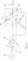
- the Figure 1 shows a drying device according to the invention, which provides compressed air for a compressed air system 1.
- Ambient air is drawn in and compressed by means of a compressor 2.
- the air heated by the compression is cooled again in a heat exchanger 3 connected downstream of the compressor 2, the heat removed being at least partially fed directly to the regeneration tank 5 and the compressed air stored therein.
- the heat exchanger or the cooling device 3 is formed by a sufficiently thick and long tube which spirally circulates around the regeneration tank 5 designed as a cylindrical pressure tank.
- the cooling coil 6 formed from the tube 7 is designed so that condensate, which may form in the tube 7 when cooling, can run off.
- the air stream cooled by means of the cooling device 3 is then fed to a filter 12, which removes any impurities from the air stream.
- the compressed, cooled and cleaned air stream is then fed to the desiccant container 4 in order to flow through an adsorbent located therein.
- the water stored in the air accumulates on the surface of the adsorbent.
- the now also dried air flow is largely stored in the downstream pressure accumulator 9 in order to be available to the compressed air system 1 when required.
- Another, smaller part of the air stream leaving the desiccant container 4 is fed to the regeneration container 5 and stored therein.
- the heat flow previously removed from the cooling device 3 is at least partially fed to the regeneration tank 5, so that the air therein is heated.
- the air flow of the compressor 2 is interrupted by means of the switching valve 14, so that the adsorbent in the desiccant container 4 can be dried by means of a so-called cold regeneration.
- the switching valve 13 By switching the switching valve 13, the air stored in the regeneration tank 5 is discharged in the opposite direction through the desiccant tank 4 and via the valve 13 and the outlet 11 into the environment.
- the compressed air coming from the regeneration container 5 is expanded to almost ambient pressure by means of an orifice or throttle 10 and is therefore very dry.
- valves 13 and 14 can be switched over again in order to initiate a new adsorption phase.
- the Figure 2 shows a structural unit 8, which is essentially formed from a cylindrical regeneration container 5 designed as a pressure container, and a tubular cooling spiral 3 that surrounds it in a spiral manner.
- the space-saving design of the drying device according to the invention is based, among other things, on the fact that the regeneration container 5 is in the Cooling coil 3 volume is arranged.
- the heat given off by the cooling coil 3 is used to heat the compressed air stored in the regeneration tank 5 and thus to increase its water absorption capacity. Due to the increased water absorption capacity of the compressed air in the regeneration tank 5, the amount of compressed air to be stored in the regeneration tank 5 can be reduced, so that the regeneration tank 5 and ultimately the entire assembly 8 can also be reduced.
Landscapes
- Engineering & Computer Science (AREA)
- Chemical & Material Sciences (AREA)
- Analytical Chemistry (AREA)
- General Chemical & Material Sciences (AREA)
- Oil, Petroleum & Natural Gas (AREA)
- Chemical Kinetics & Catalysis (AREA)
- Mechanical Engineering (AREA)
- General Engineering & Computer Science (AREA)
- Transportation (AREA)
- Drying Of Gases (AREA)
- Valves And Accessory Devices For Braking Systems (AREA)
- Drying Of Solid Materials (AREA)
Abstract
Die Erfindung betrifft eine Trocknungsvorrichtung zum Trocknen der einer Druckluftanlage (1) eines Fahrzeugs, insbesondere einer mobilen Arbeitsmaschine zugeführten Frischluft, mit einer im Frischluft-Strömungsweg einem Verdichter (2) nachgeschalteten Kühleinrichtung (3), welche Wärme aus der vom Verdichter (2) stammenden Frischluft abführt; einem im Frischluft-Strömungsweg der Kühleinrichtung (3) nachgeschalteten Trocknungsmittelbehälter (4) mit einem Adsorptionsmittel, welches der den Trocknungsmittelbehälter (4) durchströmenden Frischluft Wasser entzieht; einem im Frischluft-Strömungsweg dem Trocknungsmittelbehälter (4) nachgeschalteten Regenerationsbehälter (5), welcher einen ersten Teil der aus dem Trocknungsmittelbehälter (4) stammenden Frischluft aufnimmt und bedarfsweise wieder an den Trocknungsmittelbehälter (4) abgibt, und welcher der aufgenommenen Frischluft von der Kühleinrichtung (3) abgeführte Wärme zuführt.The invention relates to a drying device for drying the fresh air supplied to a compressed air system (1) of a vehicle, in particular a mobile machine, with a cooling device (3) which is connected downstream of a compressor (2) in the fresh air flow path and which generates heat from the compressor (2) Removes fresh air; a desiccant container (4) connected downstream in the fresh air flow path of the cooling device (3) with an adsorbent which extracts water from the fresh air flowing through the desiccant container (4); a regeneration container (5) downstream of the desiccant container (4) in the fresh air flow path, which takes up a first part of the fresh air coming from the desiccant container (4) and, if necessary, returns it to the desiccant container (4), and which of the fresh air taken in from the cooling device ( 3) supplies dissipated heat.
Description
Die vorliegende Erfindung betrifft eine Trocknungsvorrichtung zum Trocknen von Frischluft zur Versorgung einer Druckluftanlage eines Fahrzeugs, insbesondere einer mobilen Arbeitsmaschine, etwa einer Baumaschine oder eines Mobilkrans.The present invention relates to a drying device for drying fresh air for supplying a compressed air system of a vehicle, in particular a mobile work machine, such as a construction machine or a mobile crane.
Bremsanlagen von Baumaschinen, Mobilkranen und ähnlichen mobilen Kraftfahrzeugen sind in der Regel als sogenannte Druckluftbremsen ausgestaltet. Für die Erzeugung der benötigten Druckluft wird Umgebungsluft angesaugt, verdichtet und anschließend entfeuchtet, um Korrosionsschäden an der Druckluftanlage zu verhindern. Da die Verdichtung zumeist durch ölgeschmierte Kolbenverdichter erfolgt, ist zudem eine Reinigung der Frischluft erforderlich.Brake systems of construction machines, mobile cranes and similar mobile motor vehicles are usually designed as so-called air brakes. To generate the required compressed air, ambient air is sucked in, compressed and then dehumidified to prevent corrosion damage to the compressed air system. Since the compression is mostly done by oil-lubricated piston compressors, it is also necessary to clean the fresh air.
Zur Entfeuchtung der Druckluft sind verschiedene Trocknungsverfahren bekannt, welche sich der physikalischen Prinzipien der Kondensation, der Diffusion oder der Sorption (Absorption/Adsorption) bedienen. Adsorptionsverfahren werden wiederum nach der Art der Regeneration des verwendeten Adsorptionsmittels in Vakuumregenerations-, Warmregenerations- und Kaltregenerationsverfahren unterteilt.Various drying methods are known for dehumidifying the compressed air, which use the physical principles of condensation, diffusion or sorption (absorption / adsorption). Adsorption processes are again divided into vacuum regeneration, warm regeneration and cold regeneration processes according to the type of regeneration of the adsorbent used.
Bei der Trocknung der Druckluft durch Adsorption strömt die zu trocknende Luft durch ein sogenanntes Adsorptionsmittel, sodass sich in der Druckluft enthaltenes Wasser an der inneren und der äußeren Oberfläche eines porösen Adsorptionsmittels anlagert, ohne dass hierbei eine chemische Verbindung erfolgt. Hierfür weist das Adsorptionsmittel eine hohe Oberfläche auf, um das Anlagern von Wasser zu begünstigen. Gebräuchliche Adsorptionsmittel sind Aluminiumoxyd, Silikagel und Aktivkohle, aber auch Molekularsiebe.When the compressed air is dried by adsorption, the air to be dried flows through a so-called adsorbent, so that water contained in the compressed air accumulates on the inner and outer surface of a porous adsorbent without a chemical connection occurring. For this purpose, the adsorbent has a high surface area in order to promote the accumulation of water. Common adsorbents are aluminum oxide, silica gel and activated carbon, but also molecular sieves.
Sobald das Adsorptionsmittel durch Wasseranlagerungen gesättigt ist, muss das Adsorptionsmittel regeneriert werden, indem das angelagerte Wasser dem Adsorptionsmittel wieder entzogen wird. Diese sogenannte Desorption erfolgt bei der Kaltregeneration ohne zusätzliche Wärmezufuhr. Hierfür wird ein Teil der zuvor getrockneten Druckluft auf nahezu Umgebungsdruck entspannt und durch das gesättigte Adsorptionsmittel geleitet. Der durch die Entspannung extrem trockene Luftstrom nimmt das angelagerte Wasser auf und wird mit diesem über ein Auslassventil aus dem System geführt.As soon as the adsorbent is saturated with water, the adsorbent has to be regenerated by removing the accumulated water from the adsorbent. This so-called desorption takes place during cold regeneration without additional heat supply. For this purpose, part of the previously dried compressed air is expanded to almost ambient pressure and passed through the saturated adsorbent. The air flow, which is extremely dry due to the expansion, absorbs the accumulated water and is led out of the system via an outlet valve.
Um bei der Adsorptionstrocknung die Anlagerung von Wasser am Adsorptionsmittel zu begünstigen, soll die Temperatur der dem Adsorptionsmittel zugeführten Druckluft nicht wesentlich höher sein als die Temperatur der Umgebungsluft. Die zu trocknende Luft wird daher nach der Verdichtung in einen Wärmetauscher gekühlt, wobei bei bekannten Systemen die Abwärme in die Umgebung abgeführt wird.In order to promote the accumulation of water on the adsorbent during adsorption drying, the temperature of the compressed air supplied to the adsorbent should not be significantly higher than the temperature of the ambient air. The air to be dried is therefore cooled in a heat exchanger after compression, with the waste heat being dissipated to the surroundings in known systems.
Bekannte Adsorptions-Kaltregenerations-Trocknungsvorrichtungen nehmen jedoch ein erhebliches Bauvolumen ein, was beim nicht-stationären Einsatz in Fahrzeugen und den dort vorherrschenden Platzverhältnissen stets einen Nachteil darstellt.Known adsorption cold regeneration drying devices, however, take up a considerable amount of space, which is always a disadvantage in non-stationary use in vehicles and the space available there.
Es ist die Aufgabe der vorliegenden Erfindung, diesem Problem abzuhelfen und das Bauvolumen einer Adsorptions-Kaltregenerations-Trocknungsvorrichtung gegenüber bekannte Lösungen deutlich zu verringern.It is the object of the present invention to remedy this problem and to significantly reduce the construction volume of an adsorption cold regeneration drying device compared to known solutions.
Die erfindungsgemäße Trocknungsvorrichtung umfasst hierfür eine im Frischluft-Strömungsweg einem Verdichter nachgeschaltete Kühleinrichtung, welche Wärme aus der vom Verdichter stammenden Frischluft abführt, einen im Frischluft-Strömungsweg der Kühleinrichtung nachgeschalteten Trocknungsmittelbehälter mit einem Adsorptionsmittel, welches der den Trocknungsmittelbehälter durchströmenden Frischluft Wasser entzieht, und einen im Frischluft-Strömungsweg dem Trocknungsmittelbehälter nachgeschalteten Regenerationsbehälter, welcher einen ersten Teil der aus dem Trocknungsmittelbehälter stammenden Frischluft aufnimmt und bedarfsweise wieder an den Trocknungsmittelbehälter abgibt, und welcher der aufgenommenen Frischluft von der Kühleinrichtung abgeführte Wärme zuführt.For this purpose, the drying device according to the invention comprises a cooling device downstream of a compressor in the fresh air flow path, which removes heat from the fresh air originating from the compressor, a desiccant container downstream of the cooling device in the fresh air flow path with an adsorbent which extracts water from the fresh air flowing through the drying agent container, and one in Fresh air flow path downstream of the drying agent tank regeneration tank, which receives a first part of the fresh air coming from the drying agent tank and releases it back to the drying agent tank if necessary, and which supplies the absorbed fresh air with heat dissipated by the cooling device.
Mit anderen Worten wird gemäß der vorliegenden Erfindung die Wärme, welche der vom Verdichter komprimierten Luft über die Kühleinrichtung entzogen wurde, zumindest teilweise dazu genutzt, die verdichtete, getrocknete und im Regenerationsbehälter befindliche Luft zu erwärmen.In other words, according to the present invention, the heat which has been extracted from the air compressed by the compressor via the cooling device is used at least in part to heat the compressed, dried and air in the regeneration tank.
Durch diesen zusätzlichen Wärmeeintrag wird die Wasseraufnahmefähigkeit der ohnehin schon getrockneten Luft im Regenerationsbehälter weiter erhöht, was letztendlich zu einer besseren Desorption in der Regenerationsphase führt, wenn das Adsorptionsmittel von der aus dem Regenerationsbehälter stammenden Luft durchströmt wird.This additional heat input increases the water absorption capacity of the already dried air in the regeneration tank, which ultimately leads to better desorption in the regeneration phase if the adsorbent is traversed by air from the regeneration tank.
Aufgrund der besseren Trocknungsfähigkeit der im Regenerationsbehälter gespeicherten Luft kann die zur Regeneration notwendige Luftmenge und folglich auch das Volumen des Regenerationsbehälters reduziert werden, was gegenüber bekannten Lösungen zu einem verringerten Bauvolumen der Trocknungsvorrichtung führt.Due to the better drying ability of the air stored in the regeneration tank, the amount of air required for regeneration and consequently also the volume of the regeneration tank can be reduced, which leads to a reduced overall volume of the drying device compared to known solutions.
Bei einer Ausführungsform der vorliegenden Erfindung führt die Kühleinrichtung die Wärme aus der vom Verdichter komprimierten Frischluft unmittelbar an den Regenerationsbehälter ab. Dies kann dadurch erreicht werden, indem die Kühleinrichtung unmittelbar an den Regenerationsbehälter angrenzt oder sich in unmittelbarer Umgebung zu diesem befindet.In one embodiment of the present invention, the cooling device dissipates the heat from the fresh air compressed by the compressor directly to the regeneration tank. This can be achieved by the cooling device directly adjoining the regeneration tank or being in the immediate vicinity of the same.
Dabei kann die Kühleinrichtung die Wärme im Wesentlichen mittels Wärmestrahlung an den Regenerationsbehälter übertragen. Daraus folgt, dass sich die Kühleinrichtung und der Regenerationsbehälter im Wesentlichen nicht berühren. Alternativ kann die vorliegende Erfindung jedoch ebenso vorsehen, dass der Wärmestrom zwischen Kühleinrichtung und Regenerationsbehälter im Wesentlichen mittels Wärmeleitung oder Wärmetransport (Konvektion) übertragen wird. Eine primäre Übertragung mittels Wärmeleitung erfordert allerdings, dass die Kühleinrichtung und der Regenerationsbehälter gemeinsame oder stofflich direkt miteinander verbundene Elemente aufweisen. Hier ist zu beachten, dass der Regenerationsbehälter, sofern als Druckbehälter ausgeführt, bestimmte sicherheitstechnische Anforderungen erfüllen muss. Bei einer strukturellen Angliederung der Kühleinrichtung an den Regenerationsbehälter müssen diese Anforderungen selbstverständlich ebenfalls beachtet werden. Eine "Beabstandung" der Kühleinrichtung vom Regenerationsbehälter mit einer damit einhergehenden Wärmeübertragung mittels Strahlung und/oder Wärmetransport erlaubt hingegen die Verwendung standardisierter, sicherheitstechnisch bereits zertifizierter und somit kostengünstiger Bauteile für die Kühleinrichtung und insbesondere den Regenerationsbehälter.The cooling device can transfer the heat to the regeneration tank essentially by means of heat radiation. It follows that the cooling device and the regeneration tank do not essentially touch. Alternatively, however, the present invention can also provide that the heat flow between the cooling device and the regeneration tank is transmitted essentially by means of heat conduction or heat transport (convection). A However, primary transmission by means of heat conduction requires that the cooling device and the regeneration container have elements that are common or directly connected to one another in terms of material. It should be noted here that the regeneration tank, if configured as a pressure tank, must meet certain safety requirements. When structuring the cooling device to the regeneration tank, these requirements must of course also be observed. A "spacing" of the cooling device from the regeneration tank with an associated heat transfer by means of radiation and / or heat transport, on the other hand, allows the use of standardized, safety-technically already certified and therefore inexpensive components for the cooling device and in particular the regeneration tank.
In einer Ausführungsform kann die Kühleinrichtung eine Kühlwendel umfassen, insbesondere als eine Kühlwendel ausgestaltet sein. Während für die Zwecke der Kühleinrichtung grundsätzlich jeder bekannte Wärmetauscher eingesetzt werden könnte, bietet eine Kühlwendel aus einem spiralförmig gebogenen Rohr den Vorteil, dass sie sich nicht mit Eis oder Schmutzpartikeln zusetzen kann, wie dies beispielsweise bei anderen Arten von Wärmetauschern wie etwa Plattenkühlern der Fall sein kann. Den gegenüber anderen Wärmetauschern vergleichsweise hohen Platzbedarf von Kühlwendeln macht sich eine Ausführungsform der vorliegenden Erfindung dadurch zunutze, indem hier die Kühlwendel den Regenerationsbehälter umfänglich umläuft. Das ansonsten nicht nutzbare, von der Kühlwendel umlaufene Volumen wird folglich vom Regenerationsbehälter eingenommen, sodass sich das für die Trocknungsvorrichtung erforderliche Bauvolumen somit weiter reduziert.In one embodiment, the cooling device can comprise a cooling coil, in particular can be designed as a cooling coil. While basically any known heat exchanger could be used for the purposes of the cooling device, a cooling coil made of a spirally bent tube has the advantage that it cannot become clogged with ice or dirt particles, as is the case, for example, with other types of heat exchangers such as plate coolers can. An embodiment of the present invention takes advantage of the comparatively high space requirement of cooling coils compared to other heat exchangers in that the cooling coil encircles the regeneration container. The otherwise unusable volume circulated by the cooling coil is consequently taken up by the regeneration container, so that the construction volume required for the drying device is further reduced.
Eine maximale Einsparung des erforderlichen Bauvolumens wird gemäß einer weiteren Ausführungsform der vorliegenden Erfindung dadurch erreicht, dass das Füllvermögen des Regenerationsbehälters für eine vollständige Regeneration des Trocknungsmittelbehälters ausgelegt ist. Mit anderen Worten ist der Regenerationsbehälter so bemessen, dass die in ihm gespeicherte Luftmenge lediglich dazu ausreicht, eine vollständige Desorption des im Trocknungsmittelbehälter vorhandenen Adsorptionsmittels zu erreichen. Eine darüber hinausgehende Speicherkapazität des Regenerationsbehälters ist aufgrund des hierfür zusätzlich erforderlichen Bauvolumens und der fehlenden Verwendungsmöglichkeit der zusätzlich in Regenerationsbehälter gespeicherten Luftmenge hier nicht wünschenswert.According to a further embodiment of the present invention, maximum saving of the required construction volume is achieved in that the filling capacity of the regeneration container is designed for a complete regeneration of the drying agent container. In other words, the regeneration tank is dimensioned such that the amount of air stored in it is only sufficient to ensure complete desorption of the air Desiccant container to reach existing adsorbent. An additional storage capacity of the regeneration tank is not desirable here because of the additional construction volume required for this and the lack of possible use of the additional amount of air stored in the regeneration tank.
In ähnlicher Weise kann bei einer weiteren Ausführungsform der vorliegenden Erfindung das Adsorptionsvermögen des Trocknungsmittelbehälters für eine vollständige Ladung eines Druckspeichers ausgelegt sein, welcher einen zweiten Teil der aus dem Trocknungsmittelbehälter stammenden Frischluft aufnimmt und bedarfsweise an die Druckluftanlage abgibt. Mit anderen Worten kann die Beschaffenheit und Menge des im Trocknungsmittelbehälter vorhandenen Adsorptionsmittel so bemessen sein, dass dieses gerade für eine Füllung des Druckspeichers ausreicht.Similarly, in another embodiment of the present invention, the desiccant capacity of the desiccant container can be designed for a full charge of a pressure accumulator, which absorbs a second part of the fresh air coming from the desiccant container and releases it to the compressed air system if necessary. In other words, the nature and amount of the adsorbent present in the desiccant container can be dimensioned such that it is just sufficient to fill the pressure accumulator.
Gemäß einem weiteren Aspekt ermöglicht die vorliegende Erfindung ein Verfahren zum Trocknen der einer Druckluftanlage eines Fahrzeugs, insbesondere einer mobilen Arbeitsmaschine, zugeführten Frischluft, und zwar insbesondere unter Verwendung einer wie voranstehend beschriebenen Trocknungsvorrichtung.According to a further aspect, the present invention enables a method for drying the fresh air supplied to a compressed air system of a vehicle, in particular a mobile work machine, in particular using a drying device as described above.
Ein solches Verfahren kann dabei die folgenden Schritte umfassen:
- Abführen von Wärme aus mittels eines Verdichters verdichteter Frischluft in einer im Frischluft-Strömungsweg dem Verdichter nachgeschalteten Kühleinrichtung;
- Entziehen von Wasser aus der Frischluft, indem diese durch einen im Frischluft-Strömungsweg der Kühleinrichtung nachgeschalteten und ein Adsorptionsmittel aufweisenden Trocknungsmittelbehälter geleitet wird;
- Speichern eines Teils der aus dem Trocknungsmittelbehälter austretenden Frischluft in einem in Frischluft-Strömungsweg dem Trocknungsmittelbehälter nachgeschalteten Regenerationsbehälter, wobei der gespeicherten Frischluft von der Kühleinrichtung abgeführte Wärme zugeführt wird;
- bedarfsweises Abgeben der im Regenerationsbehälter gespeicherten Frischluft an den Trocknungsmittelbehälter zur Regeneration des darin enthaltenen Adsorptionsmittels.
- Dissipating heat from fresh air compressed by means of a compressor in a cooling device downstream of the compressor in the fresh air flow path;
- Extracting water from the fresh air by passing it through a desiccant container downstream of the cooling device in the fresh air flow path and having an adsorbent;
- Storing a portion of the fresh air emerging from the desiccant container in a regeneration container downstream of the desiccant container in the fresh air flow path, heat being removed from the cooling device being supplied to the stored fresh air;
- Delivery of the fresh air stored in the regeneration container to the desiccant container for regeneration of the adsorbent contained therein.
Die Erfindung wird im Folgenden anhand einer bevorzugten Ausführungsform und unter Bezugnahme auf die beiliegenden Figuren näher erläutert. Sie kann alle hierin beschriebenen Merkmale einzeln sowie in jedweder sinnvollen Kombination umfassen.The invention is explained in more detail below on the basis of a preferred embodiment and with reference to the accompanying figures. It can include all of the features described herein individually and in any meaningful combination.
Es zeigen:
- Figur 1
- Schaltplan der erfindungsgemäßen Trocknungsvorrichtung;
Figur 2- Perspektivische Ansicht einer erfindungsgemäßen Baueinheit aus einer Kühleinrichtung und einem Regenerationsbehälter.
- Figure 1
- Circuit diagram of the drying device according to the invention;
- Figure 2
- Perspective view of an assembly according to the invention from a cooling device and a regeneration tank.
Die
Mittels eines Verdichters 2 wird Umgebungsluft angesaugt und verdichtet. Die durch die Verdichtung erwärmte Luft wird in einem dem Verdichter 2 nachgeschalteten Wärmetauscher 3 wieder abgekühlt, wobei die abgeführte Wärme zumindest teilweise direkt dem Regenerationsbehälter 5 und der darin gespeicherten Druckluft zugeführt wird. Wie in der
Nachdem die Aufnahmekapazität des Adsorptionsmittels im Trocknungsmittelbehälter 4 durch die Trocknung des den Trocknungsmittelbehälter 4 durchströmenden Luftstroms erschöpft ist, wird mittels des Schaltventils 14 die Luftförderung des Verdichters 2 unterbrochen, sodass das im Trocknungsmittelbehälter 4 befindliche Adsorptionsmittel mittels einer sogenannten Kaltregeneration getrocknet werden kann. Durch Schalten des Schaltventils 13 wird die im Regenerationsbehälter 5 gespeicherte Luft in umgekehrter Richtung durch den Trocknungsmittelbehälter 4 und über das Ventil 13 und den Auslass 11 in die Umgebung abgeleitet. Vor dem Eintritt in den Trocknungsmittelbehälter 4 wird die aus dem Regenerationsbehälter 5 stammende Druckluft mittels einer Blende bzw. Drossel 10 auf nahezu Umgebungsdruck entspannt und ist somit sehr trocken. Hierdurch kann sie das vormals an der Oberfläche des Adsorptionsmittels angelagerte Wasser leicht aufnehmen und aus dem System abführen. Nach erfolgter Regeneration des Adsorptionsmittels im Trocknungsmittelbehälter 4 können die Ventile 13 und 14 wieder umgeschaltet werden, um eine erneute Adsorptionsphase einzuleiten.After the absorption capacity of the adsorbent in the
Die
Die platzsparende Ausgestaltung der erfindungsgemäßen Trocknungsvorrichtung beruht unter anderem darauf, dass der Regenerationsbehälter 5 im von der Kühlwendel 3 umlaufenen Volumen angeordnet ist. Zudem wird die von der Kühlwendel 3 abgegebene Wärme dazu genutzt, die im Regenerationsbehälter 5 gespeicherte Druckluft zu erwärmen und so deren Wasseraufnahmefähigkeit zu erhöhen. Aufgrund der erhöhten Wasseraufnahmekapazität der Druckluft im Regenerationsbehälter 5 kann die im Regenerationsbehälter 5 zu speichernde Druckluftmenge reduziert werden, sodass auch der Regenerationsbehälter 5 und letzten Endes auch die gesamte Baueinheit 8 verkleinert werden kann.The space-saving design of the drying device according to the invention is based, among other things, on the fact that the
Claims (10)
Applications Claiming Priority (1)
| Application Number | Priority Date | Filing Date | Title |
|---|---|---|---|
| DE202018104403.6U DE202018104403U1 (en) | 2018-07-31 | 2018-07-31 | Compressed air drying device |
Publications (2)
| Publication Number | Publication Date |
|---|---|
| EP3603772A1 true EP3603772A1 (en) | 2020-02-05 |
| EP3603772B1 EP3603772B1 (en) | 2020-12-23 |
Family
ID=63587843
Family Applications (1)
| Application Number | Title | Priority Date | Filing Date |
|---|---|---|---|
| EP19187166.4A Active EP3603772B1 (en) | 2018-07-31 | 2019-07-19 | Compressed air dryer |
Country Status (5)
| Country | Link |
|---|---|
| US (1) | US11413568B2 (en) |
| EP (1) | EP3603772B1 (en) |
| JP (1) | JP6840196B2 (en) |
| CN (1) | CN110772935A (en) |
| DE (1) | DE202018104403U1 (en) |
Families Citing this family (4)
| Publication number | Priority date | Publication date | Assignee | Title |
|---|---|---|---|---|
| CN111097244A (en) * | 2020-01-08 | 2020-05-05 | 杭州大盒子汽车服务有限公司 | Car washing room heat preservation system |
| CN113954805B (en) * | 2021-11-13 | 2023-05-12 | 一汽解放汽车有限公司 | Pneumatic brake system and vehicle |
| CN115532031B (en) * | 2022-10-31 | 2023-10-03 | 盐城天尔机械有限公司 | Compressed air precooler based on air heat exchange |
| CN116241437A (en) * | 2022-12-20 | 2023-06-09 | 普沃思环保科技无锡有限公司 | Air compression pretreatment system |
Citations (4)
| Publication number | Priority date | Publication date | Assignee | Title |
|---|---|---|---|---|
| DE19600377A1 (en) * | 1995-12-14 | 1997-06-19 | Wabco Gmbh | Compressed gas system |
| US7326277B1 (en) * | 2004-04-14 | 2008-02-05 | Uop Llc | Brake air drying using low pressure desiccant wheel |
| US20140116534A1 (en) * | 2012-10-30 | 2014-05-01 | Bendix Commercial Vehicle Systems Llc | Heat-exchange dryer apparatus, system and method |
| US20150251645A1 (en) * | 2014-03-05 | 2015-09-10 | Bendix Commercial Vehicle Systems Llc | Air Dryer Purge Controller and Method |
Family Cites Families (5)
| Publication number | Priority date | Publication date | Assignee | Title |
|---|---|---|---|---|
| CN2141320Y (en) * | 1992-10-20 | 1993-09-01 | 杭州汉业气源净化设备有限公司 | Dryer for purifying compressed air |
| DE102015000893B4 (en) * | 2015-01-23 | 2023-07-13 | Knorr-Bremse Systeme für Nutzfahrzeuge GmbH | Device and method for supplying a commercial vehicle with compressed air |
| WO2016187709A1 (en) * | 2015-05-22 | 2016-12-01 | Simon Fraser University | Hybrid atmospheric water generator |
| KR101838367B1 (en) * | 2016-01-21 | 2018-03-14 | 주식회사 은하에어테크 | Purge and non-purge type compressed air dryer |
| CN206288509U (en) * | 2016-11-17 | 2017-06-30 | 广东红墙新材料股份有限公司 | A kind of tank body external heat thermostat |
-
2018
- 2018-07-31 DE DE202018104403.6U patent/DE202018104403U1/en active Active
-
2019
- 2019-07-19 EP EP19187166.4A patent/EP3603772B1/en active Active
- 2019-07-25 JP JP2019136612A patent/JP6840196B2/en active Active
- 2019-07-26 CN CN201910680921.XA patent/CN110772935A/en active Pending
- 2019-07-30 US US16/526,640 patent/US11413568B2/en active Active
Patent Citations (4)
| Publication number | Priority date | Publication date | Assignee | Title |
|---|---|---|---|---|
| DE19600377A1 (en) * | 1995-12-14 | 1997-06-19 | Wabco Gmbh | Compressed gas system |
| US7326277B1 (en) * | 2004-04-14 | 2008-02-05 | Uop Llc | Brake air drying using low pressure desiccant wheel |
| US20140116534A1 (en) * | 2012-10-30 | 2014-05-01 | Bendix Commercial Vehicle Systems Llc | Heat-exchange dryer apparatus, system and method |
| US20150251645A1 (en) * | 2014-03-05 | 2015-09-10 | Bendix Commercial Vehicle Systems Llc | Air Dryer Purge Controller and Method |
Also Published As
| Publication number | Publication date |
|---|---|
| US11413568B2 (en) | 2022-08-16 |
| CN110772935A (en) | 2020-02-11 |
| DE202018104403U1 (en) | 2018-08-31 |
| JP2020019012A (en) | 2020-02-06 |
| JP6840196B2 (en) | 2021-03-10 |
| EP3603772B1 (en) | 2020-12-23 |
| US20200038799A1 (en) | 2020-02-06 |
Similar Documents
| Publication | Publication Date | Title |
|---|---|---|
| EP3603772B1 (en) | Compressed air dryer | |
| WO2013057088A1 (en) | Air filter cartridge for compressed-air preparation for a compressed-air processing installation | |
| DE19737799C2 (en) | Muffler for a compressor outlet for use in an air conditioner | |
| DE112014005908T5 (en) | Adsorber and Adsorptionskühlvorrichtung | |
| WO2007131627A1 (en) | Drying compressed air using compressor heat in a sealed regeneration cycle | |
| DE3133452A1 (en) | COMPRESSED AIR DRYER | |
| DE10358944A1 (en) | Compressor refrigeration circuit for air conditioning systems has absorption and dissipation units operating at different refrigerant pressures | |
| WO2008110365A1 (en) | Device and method for drying fluids conducted in closed circuits | |
| DE10255833A1 (en) | A method for increasing the rate of cooling in an adsorption refrigerator when the temperature is high has a second independent rapid cooling system | |
| DE112015000750T5 (en) | Refrigerant fluid circuit for thermal treatment of a motor vehicle | |
| DE10310748B3 (en) | Foreign gas removal method for vacuum sorption device using intermediate phase in which overpressure is obtained by application of heat and blocking heat output of condenser | |
| EP3255361A1 (en) | Coolant container for collecting coolant and heat exchange arrangement with such a coolant container | |
| DE102017124811A1 (en) | An air conditioning system for conditioning the air of a passenger compartment of a motor vehicle and method for operating the air conditioning system | |
| EP0317709A2 (en) | Method and apparatus for the evacuation of a refrigerant system | |
| EP2879722A1 (en) | Isolator having catalytic disinfectant decomposition | |
| DE102018008607A1 (en) | Refrigeration circuit for a motor vehicle and method for operating a refrigeration cycle for a motor vehicle | |
| DE19927879C2 (en) | Process for the air conditioning of vehicles and adsorption refrigeration system for carrying out the process | |
| EP3640442B1 (en) | Combustion engine having a system for recovering water from an exhaust gas of the combustion engine | |
| DE4413030C1 (en) | Sorption air-conditioning system (air-conditioning plant, air-conditioning set) | |
| EP2677244B1 (en) | Humidifier | |
| DE102016106091A1 (en) | Air conditioning with vacuum enclosure | |
| DE19539102A1 (en) | Sorption module for refrigerator | |
| DE102015006857B4 (en) | Adsorption memory for cooling a passenger compartment of a vehicle having an air conditioning system | |
| DE102017215018A1 (en) | Heating / cooling system for a motor vehicle | |
| EP2216611A1 (en) | Refrigerant receiver for a mobile absorption air conditioner |
Legal Events
| Date | Code | Title | Description |
|---|---|---|---|
| PUAI | Public reference made under article 153(3) epc to a published international application that has entered the european phase |
Free format text: ORIGINAL CODE: 0009012 |
|
| STAA | Information on the status of an ep patent application or granted ep patent |
Free format text: STATUS: THE APPLICATION HAS BEEN PUBLISHED |
|
| AK | Designated contracting states |
Kind code of ref document: A1 Designated state(s): AL AT BE BG CH CY CZ DE DK EE ES FI FR GB GR HR HU IE IS IT LI LT LU LV MC MK MT NL NO PL PT RO RS SE SI SK SM TR |
|
| AX | Request for extension of the european patent |
Extension state: BA ME |
|
| STAA | Information on the status of an ep patent application or granted ep patent |
Free format text: STATUS: REQUEST FOR EXAMINATION WAS MADE |
|
| 17P | Request for examination filed |
Effective date: 20200214 |
|
| RBV | Designated contracting states (corrected) |
Designated state(s): AL AT BE BG CH CY CZ DE DK EE ES FI FR GB GR HR HU IE IS IT LI LT LU LV MC MK MT NL NO PL PT RO RS SE SI SK SM TR |
|
| GRAP | Despatch of communication of intention to grant a patent |
Free format text: ORIGINAL CODE: EPIDOSNIGR1 |
|
| STAA | Information on the status of an ep patent application or granted ep patent |
Free format text: STATUS: GRANT OF PATENT IS INTENDED |
|
| GRAJ | Information related to disapproval of communication of intention to grant by the applicant or resumption of examination proceedings by the epo deleted |
Free format text: ORIGINAL CODE: EPIDOSDIGR1 |
|
| GRAP | Despatch of communication of intention to grant a patent |
Free format text: ORIGINAL CODE: EPIDOSNIGR1 |
|
| INTG | Intention to grant announced |
Effective date: 20200421 |
|
| GRAJ | Information related to disapproval of communication of intention to grant by the applicant or resumption of examination proceedings by the epo deleted |
Free format text: ORIGINAL CODE: EPIDOSDIGR1 |
|
| STAA | Information on the status of an ep patent application or granted ep patent |
Free format text: STATUS: REQUEST FOR EXAMINATION WAS MADE |
|
| GRAP | Despatch of communication of intention to grant a patent |
Free format text: ORIGINAL CODE: EPIDOSNIGR1 |
|
| INTG | Intention to grant announced |
Effective date: 20200512 |
|
| STAA | Information on the status of an ep patent application or granted ep patent |
Free format text: STATUS: GRANT OF PATENT IS INTENDED |
|
| INTC | Intention to grant announced (deleted) | ||
| INTG | Intention to grant announced |
Effective date: 20200604 |
|
| GRAJ | Information related to disapproval of communication of intention to grant by the applicant or resumption of examination proceedings by the epo deleted |
Free format text: ORIGINAL CODE: EPIDOSDIGR1 |
|
| STAA | Information on the status of an ep patent application or granted ep patent |
Free format text: STATUS: REQUEST FOR EXAMINATION WAS MADE |
|
| INTC | Intention to grant announced (deleted) | ||
| GRAS | Grant fee paid |
Free format text: ORIGINAL CODE: EPIDOSNIGR3 |
|
| STAA | Information on the status of an ep patent application or granted ep patent |
Free format text: STATUS: GRANT OF PATENT IS INTENDED |
|
| GRAP | Despatch of communication of intention to grant a patent |
Free format text: ORIGINAL CODE: EPIDOSNIGR1 |
|
| GRAA | (expected) grant |
Free format text: ORIGINAL CODE: 0009210 |
|
| STAA | Information on the status of an ep patent application or granted ep patent |
Free format text: STATUS: THE PATENT HAS BEEN GRANTED |
|
| INTG | Intention to grant announced |
Effective date: 20201102 |
|
| AK | Designated contracting states |
Kind code of ref document: B1 Designated state(s): AL AT BE BG CH CY CZ DE DK EE ES FI FR GB GR HR HU IE IS IT LI LT LU LV MC MK MT NL NO PL PT RO RS SE SI SK SM TR |
|
| REG | Reference to a national code |
Ref country code: GB Ref legal event code: FG4D Free format text: NOT ENGLISH |
|
| REG | Reference to a national code |
Ref country code: DE Ref legal event code: R096 Ref document number: 502019000578 Country of ref document: DE |
|
| REG | Reference to a national code |
Ref country code: AT Ref legal event code: REF Ref document number: 1347180 Country of ref document: AT Kind code of ref document: T Effective date: 20210115 |
|
| REG | Reference to a national code |
Ref country code: IE Ref legal event code: FG4D Free format text: LANGUAGE OF EP DOCUMENT: GERMAN |
|
| PG25 | Lapsed in a contracting state [announced via postgrant information from national office to epo] |
Ref country code: NO Free format text: LAPSE BECAUSE OF FAILURE TO SUBMIT A TRANSLATION OF THE DESCRIPTION OR TO PAY THE FEE WITHIN THE PRESCRIBED TIME-LIMIT Effective date: 20210323 Ref country code: GR Free format text: LAPSE BECAUSE OF FAILURE TO SUBMIT A TRANSLATION OF THE DESCRIPTION OR TO PAY THE FEE WITHIN THE PRESCRIBED TIME-LIMIT Effective date: 20210324 Ref country code: RS Free format text: LAPSE BECAUSE OF FAILURE TO SUBMIT A TRANSLATION OF THE DESCRIPTION OR TO PAY THE FEE WITHIN THE PRESCRIBED TIME-LIMIT Effective date: 20201223 Ref country code: FI Free format text: LAPSE BECAUSE OF FAILURE TO SUBMIT A TRANSLATION OF THE DESCRIPTION OR TO PAY THE FEE WITHIN THE PRESCRIBED TIME-LIMIT Effective date: 20201223 |
|
| REG | Reference to a national code |
Ref country code: NL Ref legal event code: MP Effective date: 20201223 |
|
| PG25 | Lapsed in a contracting state [announced via postgrant information from national office to epo] |
Ref country code: SE Free format text: LAPSE BECAUSE OF FAILURE TO SUBMIT A TRANSLATION OF THE DESCRIPTION OR TO PAY THE FEE WITHIN THE PRESCRIBED TIME-LIMIT Effective date: 20201223 Ref country code: LV Free format text: LAPSE BECAUSE OF FAILURE TO SUBMIT A TRANSLATION OF THE DESCRIPTION OR TO PAY THE FEE WITHIN THE PRESCRIBED TIME-LIMIT Effective date: 20201223 Ref country code: BG Free format text: LAPSE BECAUSE OF FAILURE TO SUBMIT A TRANSLATION OF THE DESCRIPTION OR TO PAY THE FEE WITHIN THE PRESCRIBED TIME-LIMIT Effective date: 20210323 |
|
| PG25 | Lapsed in a contracting state [announced via postgrant information from national office to epo] |
Ref country code: HR Free format text: LAPSE BECAUSE OF FAILURE TO SUBMIT A TRANSLATION OF THE DESCRIPTION OR TO PAY THE FEE WITHIN THE PRESCRIBED TIME-LIMIT Effective date: 20201223 Ref country code: NL Free format text: LAPSE BECAUSE OF FAILURE TO SUBMIT A TRANSLATION OF THE DESCRIPTION OR TO PAY THE FEE WITHIN THE PRESCRIBED TIME-LIMIT Effective date: 20201223 |
|
| REG | Reference to a national code |
Ref country code: LT Ref legal event code: MG9D |
|
| PG25 | Lapsed in a contracting state [announced via postgrant information from national office to epo] |
Ref country code: RO Free format text: LAPSE BECAUSE OF FAILURE TO SUBMIT A TRANSLATION OF THE DESCRIPTION OR TO PAY THE FEE WITHIN THE PRESCRIBED TIME-LIMIT Effective date: 20201223 Ref country code: PT Free format text: LAPSE BECAUSE OF FAILURE TO SUBMIT A TRANSLATION OF THE DESCRIPTION OR TO PAY THE FEE WITHIN THE PRESCRIBED TIME-LIMIT Effective date: 20210423 Ref country code: LT Free format text: LAPSE BECAUSE OF FAILURE TO SUBMIT A TRANSLATION OF THE DESCRIPTION OR TO PAY THE FEE WITHIN THE PRESCRIBED TIME-LIMIT Effective date: 20201223 Ref country code: CZ Free format text: LAPSE BECAUSE OF FAILURE TO SUBMIT A TRANSLATION OF THE DESCRIPTION OR TO PAY THE FEE WITHIN THE PRESCRIBED TIME-LIMIT Effective date: 20201223 Ref country code: SM Free format text: LAPSE BECAUSE OF FAILURE TO SUBMIT A TRANSLATION OF THE DESCRIPTION OR TO PAY THE FEE WITHIN THE PRESCRIBED TIME-LIMIT Effective date: 20201223 Ref country code: SK Free format text: LAPSE BECAUSE OF FAILURE TO SUBMIT A TRANSLATION OF THE DESCRIPTION OR TO PAY THE FEE WITHIN THE PRESCRIBED TIME-LIMIT Effective date: 20201223 Ref country code: EE Free format text: LAPSE BECAUSE OF FAILURE TO SUBMIT A TRANSLATION OF THE DESCRIPTION OR TO PAY THE FEE WITHIN THE PRESCRIBED TIME-LIMIT Effective date: 20201223 |
|
| PG25 | Lapsed in a contracting state [announced via postgrant information from national office to epo] |
Ref country code: PL Free format text: LAPSE BECAUSE OF FAILURE TO SUBMIT A TRANSLATION OF THE DESCRIPTION OR TO PAY THE FEE WITHIN THE PRESCRIBED TIME-LIMIT Effective date: 20201223 |
|
| REG | Reference to a national code |
Ref country code: DE Ref legal event code: R097 Ref document number: 502019000578 Country of ref document: DE |
|
| PG25 | Lapsed in a contracting state [announced via postgrant information from national office to epo] |
Ref country code: IS Free format text: LAPSE BECAUSE OF FAILURE TO SUBMIT A TRANSLATION OF THE DESCRIPTION OR TO PAY THE FEE WITHIN THE PRESCRIBED TIME-LIMIT Effective date: 20210423 |
|
| PG25 | Lapsed in a contracting state [announced via postgrant information from national office to epo] |
Ref country code: AL Free format text: LAPSE BECAUSE OF FAILURE TO SUBMIT A TRANSLATION OF THE DESCRIPTION OR TO PAY THE FEE WITHIN THE PRESCRIBED TIME-LIMIT Effective date: 20201223 |
|
| PLBE | No opposition filed within time limit |
Free format text: ORIGINAL CODE: 0009261 |
|
| STAA | Information on the status of an ep patent application or granted ep patent |
Free format text: STATUS: NO OPPOSITION FILED WITHIN TIME LIMIT |
|
| PG25 | Lapsed in a contracting state [announced via postgrant information from national office to epo] |
Ref country code: DK Free format text: LAPSE BECAUSE OF FAILURE TO SUBMIT A TRANSLATION OF THE DESCRIPTION OR TO PAY THE FEE WITHIN THE PRESCRIBED TIME-LIMIT Effective date: 20201223 |
|
| 26N | No opposition filed |
Effective date: 20210924 |
|
| PG25 | Lapsed in a contracting state [announced via postgrant information from national office to epo] |
Ref country code: ES Free format text: LAPSE BECAUSE OF FAILURE TO SUBMIT A TRANSLATION OF THE DESCRIPTION OR TO PAY THE FEE WITHIN THE PRESCRIBED TIME-LIMIT Effective date: 20201223 |
|
| PG25 | Lapsed in a contracting state [announced via postgrant information from national office to epo] |
Ref country code: SI Free format text: LAPSE BECAUSE OF FAILURE TO SUBMIT A TRANSLATION OF THE DESCRIPTION OR TO PAY THE FEE WITHIN THE PRESCRIBED TIME-LIMIT Effective date: 20201223 |
|
| PG25 | Lapsed in a contracting state [announced via postgrant information from national office to epo] |
Ref country code: MC Free format text: LAPSE BECAUSE OF FAILURE TO SUBMIT A TRANSLATION OF THE DESCRIPTION OR TO PAY THE FEE WITHIN THE PRESCRIBED TIME-LIMIT Effective date: 20201223 |
|
| REG | Reference to a national code |
Ref country code: BE Ref legal event code: MM Effective date: 20210731 |
|
| PG25 | Lapsed in a contracting state [announced via postgrant information from national office to epo] |
Ref country code: IS Free format text: LAPSE BECAUSE OF FAILURE TO SUBMIT A TRANSLATION OF THE DESCRIPTION OR TO PAY THE FEE WITHIN THE PRESCRIBED TIME-LIMIT Effective date: 20210423 Ref country code: LU Free format text: LAPSE BECAUSE OF NON-PAYMENT OF DUE FEES Effective date: 20210719 |
|
| PG25 | Lapsed in a contracting state [announced via postgrant information from national office to epo] |
Ref country code: IE Free format text: LAPSE BECAUSE OF NON-PAYMENT OF DUE FEES Effective date: 20210719 Ref country code: BE Free format text: LAPSE BECAUSE OF NON-PAYMENT OF DUE FEES Effective date: 20210731 |
|
| REG | Reference to a national code |
Ref country code: CH Ref legal event code: PL |
|
| PG25 | Lapsed in a contracting state [announced via postgrant information from national office to epo] |
Ref country code: LI Free format text: LAPSE BECAUSE OF NON-PAYMENT OF DUE FEES Effective date: 20220731 Ref country code: CH Free format text: LAPSE BECAUSE OF NON-PAYMENT OF DUE FEES Effective date: 20220731 |
|
| P01 | Opt-out of the competence of the unified patent court (upc) registered |
Effective date: 20230515 |
|
| PG25 | Lapsed in a contracting state [announced via postgrant information from national office to epo] |
Ref country code: CY Free format text: LAPSE BECAUSE OF FAILURE TO SUBMIT A TRANSLATION OF THE DESCRIPTION OR TO PAY THE FEE WITHIN THE PRESCRIBED TIME-LIMIT Effective date: 20201223 |
|
| PG25 | Lapsed in a contracting state [announced via postgrant information from national office to epo] |
Ref country code: HU Free format text: LAPSE BECAUSE OF FAILURE TO SUBMIT A TRANSLATION OF THE DESCRIPTION OR TO PAY THE FEE WITHIN THE PRESCRIBED TIME-LIMIT; INVALID AB INITIO Effective date: 20190719 |
|
| PG25 | Lapsed in a contracting state [announced via postgrant information from national office to epo] |
Ref country code: MK Free format text: LAPSE BECAUSE OF FAILURE TO SUBMIT A TRANSLATION OF THE DESCRIPTION OR TO PAY THE FEE WITHIN THE PRESCRIBED TIME-LIMIT Effective date: 20201223 |
|
| PG25 | Lapsed in a contracting state [announced via postgrant information from national office to epo] |
Ref country code: MT Free format text: LAPSE BECAUSE OF FAILURE TO SUBMIT A TRANSLATION OF THE DESCRIPTION OR TO PAY THE FEE WITHIN THE PRESCRIBED TIME-LIMIT Effective date: 20201223 |
|
| PGFP | Annual fee paid to national office [announced via postgrant information from national office to epo] |
Ref country code: DE Payment date: 20240719 Year of fee payment: 6 |
|
| PGFP | Annual fee paid to national office [announced via postgrant information from national office to epo] |
Ref country code: GB Payment date: 20240725 Year of fee payment: 6 |
|
| PGFP | Annual fee paid to national office [announced via postgrant information from national office to epo] |
Ref country code: FR Payment date: 20240730 Year of fee payment: 6 |
|
| PGFP | Annual fee paid to national office [announced via postgrant information from national office to epo] |
Ref country code: IT Payment date: 20240725 Year of fee payment: 6 |