EP3603547B1 - Papillotome for percutaneous endoscopic gastrostomy - Google Patents
Papillotome for percutaneous endoscopic gastrostomy Download PDFInfo
- Publication number
- EP3603547B1 EP3603547B1 EP19194912.2A EP19194912A EP3603547B1 EP 3603547 B1 EP3603547 B1 EP 3603547B1 EP 19194912 A EP19194912 A EP 19194912A EP 3603547 B1 EP3603547 B1 EP 3603547B1
- Authority
- EP
- European Patent Office
- Prior art keywords
- catheter
- free end
- front opening
- cutting
- opening
- Prior art date
- Legal status (The legal status is an assumption and is not a legal conclusion. Google has not performed a legal analysis and makes no representation as to the accuracy of the status listed.)
- Active
Links
- 238000005520 cutting process Methods 0.000 claims description 106
- 210000002784 stomach Anatomy 0.000 description 21
- 238000000034 method Methods 0.000 description 11
- 210000001519 tissue Anatomy 0.000 description 7
- 210000003815 abdominal wall Anatomy 0.000 description 6
- 239000000523 sample Substances 0.000 description 5
- 208000012868 Overgrowth Diseases 0.000 description 4
- 201000001883 cholelithiasis Diseases 0.000 description 4
- 208000001130 gallstones Diseases 0.000 description 4
- 238000001574 biopsy Methods 0.000 description 3
- 230000000740 bleeding effect Effects 0.000 description 3
- 230000000694 effects Effects 0.000 description 3
- 239000012530 fluid Substances 0.000 description 3
- 238000002350 laparotomy Methods 0.000 description 3
- 210000005070 sphincter Anatomy 0.000 description 3
- 208000036829 Device dislocation Diseases 0.000 description 2
- 208000002847 Surgical Wound Diseases 0.000 description 2
- 210000000013 bile duct Anatomy 0.000 description 2
- 238000007463 endoscopic sphincterotomy Methods 0.000 description 2
- 210000001156 gastric mucosa Anatomy 0.000 description 2
- 208000015181 infectious disease Diseases 0.000 description 2
- 210000004877 mucosa Anatomy 0.000 description 2
- 210000003205 muscle Anatomy 0.000 description 2
- 238000002271 resection Methods 0.000 description 2
- 206010033645 Pancreatitis Diseases 0.000 description 1
- 206010052428 Wound Diseases 0.000 description 1
- 208000027418 Wounds and injury Diseases 0.000 description 1
- 230000001154 acute effect Effects 0.000 description 1
- 210000004204 blood vessel Anatomy 0.000 description 1
- 208000003167 cholangitis Diseases 0.000 description 1
- 239000002872 contrast media Substances 0.000 description 1
- 210000001198 duodenum Anatomy 0.000 description 1
- 210000003811 finger Anatomy 0.000 description 1
- 230000002496 gastric effect Effects 0.000 description 1
- 239000000463 material Substances 0.000 description 1
- -1 polytetrafluoroethylene Polymers 0.000 description 1
- 229920001343 polytetrafluoroethylene Polymers 0.000 description 1
- 239000004810 polytetrafluoroethylene Substances 0.000 description 1
- 238000007464 sphincterotomy Methods 0.000 description 1
- 229910001220 stainless steel Inorganic materials 0.000 description 1
- 239000010935 stainless steel Substances 0.000 description 1
- 239000006228 supernatant Substances 0.000 description 1
- 210000003813 thumb Anatomy 0.000 description 1
- 230000007704 transition Effects 0.000 description 1
- 230000000304 vasodilatating effect Effects 0.000 description 1
Images

Classifications
-
- A—HUMAN NECESSITIES
- A61—MEDICAL OR VETERINARY SCIENCE; HYGIENE
- A61B—DIAGNOSIS; SURGERY; IDENTIFICATION
- A61B17/00—Surgical instruments, devices or methods, e.g. tourniquets
- A61B17/32—Surgical cutting instruments
- A61B17/320016—Endoscopic cutting instruments, e.g. arthroscopes, resectoscopes
-
- A—HUMAN NECESSITIES
- A61—MEDICAL OR VETERINARY SCIENCE; HYGIENE
- A61B—DIAGNOSIS; SURGERY; IDENTIFICATION
- A61B17/00—Surgical instruments, devices or methods, e.g. tourniquets
- A61B17/32—Surgical cutting instruments
- A61B17/3205—Excision instruments
- A61B17/32056—Surgical snare instruments
-
- A—HUMAN NECESSITIES
- A61—MEDICAL OR VETERINARY SCIENCE; HYGIENE
- A61B—DIAGNOSIS; SURGERY; IDENTIFICATION
- A61B18/00—Surgical instruments, devices or methods for transferring non-mechanical forms of energy to or from the body
- A61B18/04—Surgical instruments, devices or methods for transferring non-mechanical forms of energy to or from the body by heating
- A61B18/12—Surgical instruments, devices or methods for transferring non-mechanical forms of energy to or from the body by heating by passing a current through the tissue to be heated, e.g. high-frequency current
- A61B18/14—Probes or electrodes therefor
-
- A—HUMAN NECESSITIES
- A61—MEDICAL OR VETERINARY SCIENCE; HYGIENE
- A61B—DIAGNOSIS; SURGERY; IDENTIFICATION
- A61B17/00—Surgical instruments, devices or methods, e.g. tourniquets
- A61B17/22—Implements for squeezing-off ulcers or the like on the inside of inner organs of the body; Implements for scraping-out cavities of body organs, e.g. bones; Calculus removers; Calculus smashing apparatus; Apparatus for removing obstructions in blood vessels, not otherwise provided for
-
- A—HUMAN NECESSITIES
- A61—MEDICAL OR VETERINARY SCIENCE; HYGIENE
- A61B—DIAGNOSIS; SURGERY; IDENTIFICATION
- A61B17/00—Surgical instruments, devices or methods, e.g. tourniquets
- A61B17/00234—Surgical instruments, devices or methods, e.g. tourniquets for minimally invasive surgery
- A61B2017/00292—Surgical instruments, devices or methods, e.g. tourniquets for minimally invasive surgery mounted on or guided by flexible, e.g. catheter-like, means
- A61B2017/003—Steerable
- A61B2017/00318—Steering mechanisms
- A61B2017/00323—Cables or rods
-
- A—HUMAN NECESSITIES
- A61—MEDICAL OR VETERINARY SCIENCE; HYGIENE
- A61B—DIAGNOSIS; SURGERY; IDENTIFICATION
- A61B18/00—Surgical instruments, devices or methods for transferring non-mechanical forms of energy to or from the body
- A61B2018/00315—Surgical instruments, devices or methods for transferring non-mechanical forms of energy to or from the body for treatment of particular body parts
- A61B2018/00482—Digestive system
- A61B2018/00494—Stomach, intestines or bowel
-
- A—HUMAN NECESSITIES
- A61—MEDICAL OR VETERINARY SCIENCE; HYGIENE
- A61B—DIAGNOSIS; SURGERY; IDENTIFICATION
- A61B18/00—Surgical instruments, devices or methods for transferring non-mechanical forms of energy to or from the body
- A61B2018/00571—Surgical instruments, devices or methods for transferring non-mechanical forms of energy to or from the body for achieving a particular surgical effect
- A61B2018/00595—Cauterization
-
- A—HUMAN NECESSITIES
- A61—MEDICAL OR VETERINARY SCIENCE; HYGIENE
- A61B—DIAGNOSIS; SURGERY; IDENTIFICATION
- A61B18/00—Surgical instruments, devices or methods for transferring non-mechanical forms of energy to or from the body
- A61B2018/00571—Surgical instruments, devices or methods for transferring non-mechanical forms of energy to or from the body for achieving a particular surgical effect
- A61B2018/00601—Cutting
-
- A—HUMAN NECESSITIES
- A61—MEDICAL OR VETERINARY SCIENCE; HYGIENE
- A61B—DIAGNOSIS; SURGERY; IDENTIFICATION
- A61B18/00—Surgical instruments, devices or methods for transferring non-mechanical forms of energy to or from the body
- A61B18/04—Surgical instruments, devices or methods for transferring non-mechanical forms of energy to or from the body by heating
- A61B18/12—Surgical instruments, devices or methods for transferring non-mechanical forms of energy to or from the body by heating by passing a current through the tissue to be heated, e.g. high-frequency current
- A61B18/14—Probes or electrodes therefor
- A61B2018/1405—Electrodes having a specific shape
- A61B2018/1407—Loop
-
- A—HUMAN NECESSITIES
- A61—MEDICAL OR VETERINARY SCIENCE; HYGIENE
- A61B—DIAGNOSIS; SURGERY; IDENTIFICATION
- A61B18/00—Surgical instruments, devices or methods for transferring non-mechanical forms of energy to or from the body
- A61B18/04—Surgical instruments, devices or methods for transferring non-mechanical forms of energy to or from the body by heating
- A61B18/12—Surgical instruments, devices or methods for transferring non-mechanical forms of energy to or from the body by heating by passing a current through the tissue to be heated, e.g. high-frequency current
- A61B18/14—Probes or electrodes therefor
- A61B2018/1405—Electrodes having a specific shape
- A61B2018/144—Wire
Definitions
- the invention relates to a papillotome for percutaneous endoscopic gastrostomy (PEG), which has a) a handle, b) an elongated, flexible catheter which is attached to the handle, which has a free end region with a free end and which has at least one first lumen , c) a front opening which is located in the free end area and connects the first lumen to an outside of the catheter, d) a rear opening which is located in the free end area which is further away from the free end than the front opening and the connects the first lumen to the outside, the anterior opening and the posterior opening being arranged in the same orientation to the catheter, and e) a cutting wire which is axially displaceable in the first lumen which extends through the anterior opening and the posterior opening, which is located between the front opening and the rear opening on the outside and which is fixed in the free end area and in the handle is laid, the cutting wire is tensioned when the handle is operated, the free end area is deformed in an arc and the cutting wire forms
- the cutting wire emerges at this free end and is located on the outside of the catheter up to the second opening.
- the cutting wire is displaced relative to the catheter and the catheter is bent or deformed into a U-shape between the front and a second, rear opening.
- the cutting wire connects the front opening with the second opening direct.
- a loop is formed between the cutting wire and the bent free end region of the catheter.
- the cutting wire is connected to a radio frequency (RF) voltage source.
- RF radio frequency
- the cutting wire can be used to cut in a known manner and according to the prior art. The cutting path is determined by the movement of the catheter.
- Loop papillotomes of this type have proven themselves especially for endoscopic use, in particular for the removal of gallstones.
- the papilla vateri or the sphincter oddi muscle is severed. Tissue that looks beyond a certain level can be severed.
- a papillotome of the generic type mentioned in the preamble of claim 1, which is essentially designed with the aforementioned features and is intended for this application, is based on U.S. 6,017,340 A emerged.
- Such a papillotome should accordingly be used in the endoscopic sphincterotomy in connection with an endoscope in order to enable a surgical incision within a patient.
- Such a papillotome will preferably be used to partially cut open the duodenum on the papilla vateri so that gallstones which form an obstruction can be removed.
- Major complications such as bleeding, pancreatitis perforation, and cholangitis can occur with endoscopic sphincterotomy.
- a cutting wire of the papillotome is fixed to the catheter at an axial distance from the distal end of the catheter, wherein in one embodiment the catheter is provided with a modified distal tip in order to facilitate the cannulation of the sphincter of the papilla by means of this profile.
- an asymmetrically opening and closing HF surgical resection loop which has an insulated, curved loop section and a non-insulated loop section which forms a cutting edge.
- the resection loop extends beyond a distal end of a catheter.
- a transition from the insulated loop section to the non-insulated loop section is intended have the shape of a spur, which is intended to ensure a certain distance between the non-insulated loop section and the tissue and thus unintentional cutting.
- the needle knife which is used in conjunction with an endoscope to perform a surgical incision within a patient.
- it is intended to be used for a sphincterotomy in which an incision is made in a sphincter muscle.
- the needle knife which is arranged distally on the catheter, can be used not only for the cutting function but also for fluid communication (for example rinsing fluid, radio contrast medium) and for suctioning off tissue, and for this purpose it can be designed to be hollow.
- the distal end of the catheter and thus the needle knife are controlled by means of a puller wire running in a lumen and connected to the distal end of the catheter.
- the puller wire can also be electrically conductive and take on the function of a cutting wire sphincterotome.
- the U.S. 5,396,902 A relates to a wire guide or probe assembly for inserting a medical catheter or electrical leads to a desired location within a patient's body.
- the aim is to create a simple and easy-to-use probe and manipulation handle arrangement in order to give the distal end of a supply line or a catheter a dynamic curvature while it is being pushed through a blood vessel.
- a puller wire running in a lumen of the catheter is intended to interact mechanically with the distal tip, similar to a papillotome. This should run to the distal end of the catheter and be fixed there.
- the puller wire exits and re-enters the lumen via two openings, and runs between these openings along the outside of the catheter.
- Buried bumper syndrome is an ingrown PEG retaining plate on a PEG tube.
- a PEG tube is passed through the abdominal wall and the patient the stomach wall (percutaneously) inserted into the stomach.
- the patient is supplied with food and fluids via this probe.
- the PEG probe has a PEG catheter. This is connected outside of the body to a connection system of the PEG probe, which is then connected to the inside of the stomach via the PEG catheter.
- the PEG catheter runs through the abdominal wall and stomach wall. Inadequate or incorrect care can result in the PEG holding plate being enclosed and overgrown by the gastric mucosa of the stomach wall (gastric mucosa). This is known as buried bumper syndrome.
- ingrown PEG retaining plates are removed by laparotomy, by means of the pull method or the push method.
- a laparotomy is the surgical opening of the abdominal wall.
- the stomach wall is also opened and the ingrown PEG retaining plate is cut free from the outside. This is a complex, highly invasive and therefore risky operation that is only used in rare cases.
- the pull process is based on removing the ingrown PEG holding plate from the tissue by pulling it from the outside after cutting the surrounding tissue beforehand.
- Biopsy forceps are inserted through the lying PEG catheter to stiffen it and opened as a resistance.
- the abdominal wall bulges at the site of the ingrown PEG holding plate.
- With a scalpel the abdominal wall and part of the stomach wall in the immediate vicinity of the PEG catheter are cut through to the PEG holding plate.
- the PEG holding plate is then pulled free from the outside using the biopsy forceps. This procedure is less invasive than a laparotomy, but even here part of the abdominal wall and stomach wall is severed, which is fraught with the associated risks.
- the PEG holding plate is cut free from the inside, i.e. from the inside of the stomach, under endoscopic control.
- a cutting tool and the PEG holding plate are inserted endoscopically or percutaneously into the inside of the stomach exposed.
- needle papillotomes are used for this, these have a needle-like cutting tool at their tip with which the tissue can be cut. They are usually introduced endoscopically.
- Loop papillotomes can also be used; these are inserted percutaneously through the PEG catheter. To do this, they are pushed forward through the PEG catheter in a relaxed state, not bent.
- the handle is actuated and the papillotome loop is formed.
- the cutting wire is drawn onto the tissue surrounding the PEG holding plate; this can now be incised until the cutting wire hits the PEG holding plate. Usually several of these radial cuts are made until the PEG holding plate is exposed.
- the PEG holding plate is then pushed into the inside of the stomach with a commercially available bougie, or dilator, pushed through the PEG catheter. The freed PEG holding plate can then be removed endoscopically.
- Bougies are body orifices or vasodilating medical devices mostly made of stainless steel or other hard materials with a conical shape.
- the push procedure is the least invasive procedure and offers the lowest complication rate of the procedures presented.
- problems and complications also arise here. Disadvantages of the push technique are the frequent slipping or slipping of the papillotome loop when it is pulled back onto the PEG holding plate, which leads to greater bleeding, larger foci of infection and higher workload. Furthermore, the side of the PEG holding plate cannot be exposed.
- the existing bougies are not designed for use with and for a PEG tube.
- the object of the invention to provide a device for the push method with which the intervention can be carried out in a more targeted and simple manner, the papillotome is prevented from slipping and the incisions can be made in a more targeted manner.
- a cutting tip is formed at the free end of the catheter, which is connected to the cutting wire and forms the foremost end of the papillotome, the cutting wire also being between the free end and the front opening is on the outside, there forms the cutting tip and a longitudinally extending cutting edge and is arranged there in the same orientation to the catheter as the front opening and the rear opening.
- the front opening is arranged at a distance of at least 3 mm from the free end, and a protrusion is formed between the free end and the front opening.
- the cutting wire is also located between the free end and the front opening on the outside and forms the longitudinal cutting edge there, which is arranged in the same orientation to the catheter as the front opening and the rear opening.
- the longitudinal cutting edge is formed by the cutting wire itself.
- the cutting wire does not begin directly at the free end of the free end region of the catheter, but at a distance from the free end. This allows the overhang to serve as a stop. After the free end area has been introduced into the inside of the stomach, the free end area is still essentially straight. If the handle is now operated and the free end area is bent as a result, the overhang strikes a lateral edge of an overgrowth of the PEG holding plate. This results in a certain and to a certain extent fixed position of the protrusion. In its free end region, the papillotome acts like a pair of forceps, that is, between the protrusion and the catheter on the other side of the rear opening, clamping takes place.
- the part of the PEG holding plate located there is gripped over and clamped.
- the cutting wire is also supported and fixed in the vicinity of the front opening. It is not only held in place by the catheter itself. If a surgeon pulls the catheter outwards and makes a cut, then not only that part of the transverse cutting edge that is located near the second opening, where the pull has a particular effect, preferably cuts, but also that part of the cutting wire that is located near the front opening because this is where the support described takes place.
- the longitudinal cutting edge that extends outside also cuts of the shell of the disc-shaped PEG holding plate is located.
- the loop can be made smaller and the effect of the longitudinal cutting edge can be controlled.
- the effect of the transverse cutting edge can be influenced by pulling on the catheter.
- the cutting wire protrudes outwards from the free end.
- This area of the cutting wire forms a cutting tip. It is entirely possible and provided that the cutting tip is at a certain distance of e.g. 1-8 mm from the free end of the catheter, i.e. protrudes freely from the first lumen by this amount.
- This also serves the following purpose: Depending on the extent to which the PEG holding plate is overgrown, it can happen that the inner opening of the PEG catheter has overgrown into the inside of the stomach. In these cases, the overgrowth is loosened and cut through with the front cutting tip when inserting the catheter. This allows the way to the inside of the stomach to be cut. Only then is the free end area of the papillotome in the inside of the stomach.
- the cutting tip enables a hooking in the stomach wall after or during the flexion of the papillotome. This also prevents the free end area from slipping. Such slippage can also occur when the catheter is withdrawn. Uncontrolled cutting of the cutting wire into the overgrowth is prevented, or at least made more difficult. Unspecified and unclean cuts, larger wound areas and thus avoidable bleeding and foci of infection are avoided.
- the protrusion can only be formed by an area of the catheter.
- the transverse cutting edge and the longitudinal cutting edge are in the same orientation to the catheter. This means the following: If you look at the catheter in the axial direction, the two openings are in the same angular position. This means that the cutting wire of both cutting edges is also in the same angular position.
- the free end of the catheter has a bevel.
- the angle of the bevel is in particular about 45 °, deviations of ⁇ 20 ° are possible.
- a point is formed by the bevel. This tip preferably has the same orientation to the catheter as the anterior opening and the posterior opening.
- the length of the protrusion preferably corresponds at least to the thickness of the PEG holding plate used. This length is adapted to the thickness. With thin retaining plates, the overhang can be selected smaller, with thick retaining plates correspondingly larger. In addition, there is the thickness of the overgrowth, which is not always known.
- a third opening can be formed in the catheter. It is located between the front opening and the rear opening. It is in the immediate vicinity of the front opening, in particular 1 to 8 mm away from it. It is oriented in the same way as the other two openings.
- the wire that forms the longitudinally extending cutting edge can be introduced into or out of the catheter through the third opening.
- the longitudinal cutting edge can now be designed in such a way that it forms a point of intersection with the transverse cutting edge. This improves cutting where the two cutting edges meet.
- the front opening is preferably only used for the wire that forms the transverse cut edge.
- the transverse cutting edge can also be formed by a rope.
- a rope has the advantage that in the bent state of the free area it runs essentially in a straight line between the two openings. With a cutting wire that has only one filament, this is not always fully achieved.
- the handle is preferably designed such that the catheter is connected to a stationary part of the handle, while a movable, in particular displaceable part of the handle is connected to the cutting wire. If the movable part is then pulled outwards, the flexion occurs.
- the catheter preferably has a length between 40 and 150 cm, preferably from 50 to 120 cm.
- Commercially available papillotomes are designed to be significantly longer due to their endoscopic introduction and the design for the bile duct. A shorter length enables unhindered work.
- the catheter is made of, for example, polytetrafluoroethylene. It has a diameter of 2 to 4 mm. It preferably has two lumens; the second lumen is used for a guide wire, which is the state of the art in a push procedure.
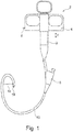
- the papillotome has a handle 2 with a stationary part 3 and a movable part 4, which is designed here as a slide that is guided on the stationary part 3 so as to be displaceable.
- the stationary part 3 has an eyelet, and two corresponding openings are provided on the movable part 4. A finger or a thumb can be inserted into each of these, and the movable part 4 can be displaced by moving.
- An HF connection 6 is provided on the movable part 4. The movement is shown by arrow 7. At the lower end of the stationary part 3, this merges into a catheter 10. It is designed with two lumen, see FIG Figure 4 .
- a second lumen 14 is accessible via an attachment 8. This ends with a screw thread.
- a guide wire 18 can be inserted here ( Figure 3 ).
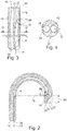
- the catheter 10 has a free end region. This extends to Figure 2 from a foremost tip of the papillotome to a little beyond a rear opening 9.
- the front end region is that part of the catheter 10 that can be converted from a stretched to a flexed state, the flexed state is in the Figures 1 and 2 shown.
- a cutting wire 16 is guided displaceably in a first lumen 12. He is with the movable part 4 and the RF connector 6 after Figure 1 connected. In the bent state like him Figure 2 shows, a tensile force acts on the cutting wire 16 in accordance with the arrow 13.
- the cutting wire 16 is stretched between the rear opening 9 and a front opening 11; After passing through the front opening 11, the cutting wire 16 runs in the first lumen 12 to a free end 17, where it emerges from the first lumen 12 and is bent around the tube end of the catheter 10 there. It is led along the outside. It re-enters the first lumen 12 through a third opening 60.
- the third opening 60 is located between the front opening 11 and the rear opening 9.
- the third opening 60 is also oriented towards the catheter 10 as the two other openings 9, 11. After passing through the third opening, the cutting wire 16 is inserted deeper into the first lumen 12 and possibly secured by an angled portion (as shown).
- the free end is not cut off at an acute angle, as in particular from Figure 2 can be seen, rather it is cut off at an angle of 90 °.
- the angle according to Figure 2 can be between 10 and 80 °, it is preferably 45 °.
- a guide wire 18 is introduced into the second lumen 14.
- the course of the cutting wire 16 is similar to that in the first exemplary embodiment, but with the following difference: After passing the front opening 11, the cutting wire 16 runs in the first lumen 12 in the direction of the rear opening 9 and exits the first lumen 12 via the third opening 60 is then bent around the free end 17 of the catheter 10 and inserted into the first lumen 12. It has any length in it. It may be secured by a bend. This can be hooked with the short piece between the front opening 11 and the third opening 60 of the cutting wire 16 or the piece of the cutting wire 16 on the other side of the rear opening 9.
- the length of the protrusion 20 in the first embodiment is practically equal to the length between a point of intersection of the longitudinal cutting edge 19 with the transverse cutting edge 15 and a cutting tip 22.
- the protrusion 20 is slightly longer than the distance between the front opening 11 and the free one End, because the cutting wire 16 is bent around the tube end of the catheter 10 and there contributes to the length of the protrusion. At its deflection at the tip of the free end 17, the cutting wire 16 forms the cutting tip 22.
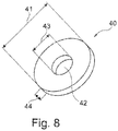
- the Figure 8 shows a commercially available PEG retaining plate 40. It has a passage 42. It is designed as a circular disk. Its thickness is denoted by 44, 41 is its outer diameter, 43 is the hole diameter.
- FIG 9 shows such a PEG holding plate 40 which has grown into a stomach wall 50.
- the PEG holding plate 40 is connected to a PEG catheter 46. It can be seen that the gastric outlet of the PEG catheter 46, which was previously overgrown by mucosa, was opened; this was done by means of the cutting tip 22.
- the papillotome is already shown in a position in which a cutting process can take place.
- the cutting tip 22 is in contact with the muscosa, the transverse cutting edge 15 rests on the inside of the mucosa.
- the inside of the stomach is in Figure 9 above. If HF voltage is now applied to the cutting wire 16 and the catheter 10 is pulled down, a cutting process takes place.
- the cutting wire 16 can be pulled even further in the direction of the arrow 13 in order to support the cutting process through the longitudinal cutting edge 19. This can continue until contact is made with the periphery of the PEG retainer plate 40.
- Both cutting edges 15, 19 can thus be used separately and in a targeted manner.
- the transverse cutting edge 15 is controlled by moving the catheter 10 in the axial direction and rotating the catheter 10 about the axial direction.
- the longitudinal cutting edge 19 is controlled in the opposite direction by pulling it in the direction of arrow 13 and letting go of the cutting wire 16.
- a papillotome for percutaneous endoscopic gastrostomy has a front opening 11 which is located in a free end region of a catheter 10 and at the exit of a first lumen 12, a rear opening 9 which is further away from a free end 17 than the front opening 11 and which connects the first lumen 12 to the outside, and a cutting wire 16 which is axially slidable in the first lumen 12, which extends through the front opening 11 and the rear opening 9, which extends between the front opening 11 and the rear Opening 9 is located on the outside, wherein when the cutting wire 16 is tensioned, the free end region is deformed in an arc shape and the cutting wire 16 forms a transverse cutting edge 15 between the front opening 11 and the rear opening 9.
- the front opening 11 is arranged at a distance of at least 3 mm from the free end 17.
- a protrusion 20 is formed between the free end 17 and the front opening 11.
- a cutting tip 20 is formed which is connected to the cutting wire 16 and forms the foremost end of the papillotome.
Landscapes
- Health & Medical Sciences (AREA)
- Life Sciences & Earth Sciences (AREA)
- Surgery (AREA)
- Engineering & Computer Science (AREA)
- Medical Informatics (AREA)
- Veterinary Medicine (AREA)
- Biomedical Technology (AREA)
- Heart & Thoracic Surgery (AREA)
- Nuclear Medicine, Radiotherapy & Molecular Imaging (AREA)
- Molecular Biology (AREA)
- Animal Behavior & Ethology (AREA)
- General Health & Medical Sciences (AREA)
- Public Health (AREA)
- Orthopedic Medicine & Surgery (AREA)
- Physics & Mathematics (AREA)
- Plasma & Fusion (AREA)
- Otolaryngology (AREA)
- Media Introduction/Drainage Providing Device (AREA)
- Surgical Instruments (AREA)
Description
Die Erfindung betrifft ein Papillotom für die perkutane endoskopische Gastrostomie (PEG), das aufweist a) einen Handgriff, b) einen länglichen, biegbaren Katheter, der am Handgriff befestigt ist, der einen freien Endbereich mit einem freien Ende und der mindestens ein erstes Lumen aufweist, c) eine vordere Öffnung, die sich im freien Endbereich befindet und das erste Lumen mit einer Außenseite des Katheters verbindet, d) eine hintere Öffnung, die sich im freien Endbereich befindet, die weiter entfernt vom freien Ende ist als die vordere Öffnung und die das erste Lumen mit der Außenseite verbindet, wobei die vordere Öffnung und die hintere Öffnung in derselben Orientierung zum Katheter angeordnet sind, und e) einen Schneidedraht, der sich axial verschiebbar im ersten Lumen befindet, der durch die vordere Öffnung und die hinteren Öffnung verläuft, der sich zwischen der vorderen Öffnung und der hinteren Öffnung auf der Außenseite befindet und der im freien Endbereich und im Handgriff festgelegt ist, wobei bei betätigtem Handgriff der Schneidedraht gespannt ist, der freie Endbereich bogenförmig verformt ist und der Schneidedraht zwischen der vorderen Öffnung und der hinteren Öffnung eine quer verlaufende Schnittkante bildet, wobei die vordere Öffnung in einem Abstand von mindestens 3 mm vom freien Ende angeordnet ist und zwischen dem freien Ende und der vorderen Öffnung ein Überstand ausgebildet ist.The invention relates to a papillotome for percutaneous endoscopic gastrostomy (PEG), which has a) a handle, b) an elongated, flexible catheter which is attached to the handle, which has a free end region with a free end and which has at least one first lumen , c) a front opening which is located in the free end area and connects the first lumen to an outside of the catheter, d) a rear opening which is located in the free end area which is further away from the free end than the front opening and the connects the first lumen to the outside, the anterior opening and the posterior opening being arranged in the same orientation to the catheter, and e) a cutting wire which is axially displaceable in the first lumen which extends through the anterior opening and the posterior opening, which is located between the front opening and the rear opening on the outside and which is fixed in the free end area and in the handle is laid, the cutting wire is tensioned when the handle is operated, the free end area is deformed in an arc and the cutting wire forms a transverse cutting edge between the front opening and the rear opening, the front opening being arranged at a distance of at least 3 mm from the free end and a protrusion is formed between the free end and the front opening.
Aus
Bei den vorbekannten Papillotomen befindet sich eine vordere Öffnung am freien Ende des Katheters. Der Schneidedraht tritt an diesem freien Ende aus und befindet sich bis zur zweiten Öffnung an der Außenseite des Katheters. Durch Betätigen des Handgriffs wird der Schneidedraht gegenüber dem Katheter verschoben und der Katheter zwischen der vorderen und einer zweiten, hinteren Öffnung gebeugt bzw. U-förmig verformt. Der Schneidedraht verbindet die vordere Öffnung mit der zweiten Öffnung direkt. Zwischen Schneidedraht und dem gebeugten freien Endbereich des Katheters wird eine Schlinge ausgebildet. Der Schneidedraht ist mit einer Hochfrequenz (HF)-Spannungsquelle verbunden. In bekannter Weise und nach dem Stand der Technik kann mit dem Schneidedraht geschnitten werden. Der Schnittweg wird durch die Bewegung des Katheters bestimmt.In the previously known papillotomes, there is a front opening at the free end of the catheter. The cutting wire emerges at this free end and is located on the outside of the catheter up to the second opening. By operating the handle, the cutting wire is displaced relative to the catheter and the catheter is bent or deformed into a U-shape between the front and a second, rear opening. The cutting wire connects the front opening with the second opening direct. A loop is formed between the cutting wire and the bent free end region of the catheter. The cutting wire is connected to a radio frequency (RF) voltage source. The cutting wire can be used to cut in a known manner and according to the prior art. The cutting path is determined by the movement of the catheter.
Schlingen-Papillotome dieser Art haben sich speziell für die endoskopische Anwendung, insbesondere zur Entfernung von Gallensteinen, bewährt. Dabei wird in der Regel der papilla vateri bzw. der musculus sphincter oddi durchtrennt. Gewebe, das über ein gewisses Niveau herausschaut, kann durchtrennt werden.Loop papillotomes of this type have proven themselves especially for endoscopic use, in particular for the removal of gallstones. As a rule, the papilla vateri or the sphincter oddi muscle is severed. Tissue that looks beyond a certain level can be severed.
Ein Papillotom der im Oberbegriff des Anspruchs 1 genannten Gattung, das im Wesentlichen mit den vorgenannten Merkmalen ausgeführt und für diese Anwendung vorgesehen ist, geht aus der
Aus der
Aus der
Die
Bei einem Buried Bumper-Syndrom geht es um eine eingewachsene PEG-Halteplatte einer PEG-Sonde. Eine PEG-Sonde wird dem Patienten durch die Bauchdecke und die Magenwand (perkutan) in den Magen eingesetzt. Über diese Sonde wird der Patient mit Nahrung und Flüssigkeit versorgt. Die PEG-Sonde weist einen PEG-Katheter auf. Dieser wird außerhalb des Körpers mit einem Anschlusssystem der PEG-Sonde verbunden, das dann über den PEG-Katheter mit dem Mageninneren verbunden ist. Der PEG-Katheter verläuft durch die Bauchdecke und die Magenwand. Bei unzureichender oder falscher Pflege kann es dazu kommen, dass die PEG-Halteplatte von der Magenschleimhaut der Magenwand (Magenmukosa) umschlossen und überwachsen wird. Dies wird als Buried Bumper Syndrom bezeichnet.Buried bumper syndrome is an ingrown PEG retaining plate on a PEG tube. A PEG tube is passed through the abdominal wall and the patient the stomach wall (percutaneously) inserted into the stomach. The patient is supplied with food and fluids via this probe. The PEG probe has a PEG catheter. This is connected outside of the body to a connection system of the PEG probe, which is then connected to the inside of the stomach via the PEG catheter. The PEG catheter runs through the abdominal wall and stomach wall. Inadequate or incorrect care can result in the PEG holding plate being enclosed and overgrown by the gastric mucosa of the stomach wall (gastric mucosa). This is known as buried bumper syndrome.
Nach dem Stand der Technik werden eingewachsene PEG-Halteplatten per Laparotomie, mittels des Pull-Verfahrens oder des Push-Verfahrens entfernt.According to the prior art, ingrown PEG retaining plates are removed by laparotomy, by means of the pull method or the push method.
Unter einer Laparotomie versteht man die chirurgische Öffnung der Bauchdecke. Im Zuge dieser Operation wird auch die Magenwand geöffnet und die eingewachsene PEG-Halteplatte von außen freigeschnitten. Dies ist eine aufwändige, stark invasive und daher risikoreiche Operation, die nur noch in seltenen Fällen angewandt wird.A laparotomy is the surgical opening of the abdominal wall. In the course of this operation, the stomach wall is also opened and the ingrown PEG retaining plate is cut free from the outside. This is a complex, highly invasive and therefore risky operation that is only used in rare cases.
Das Pull-Verfahren basiert darauf, die eingewachsene PEG-Halteplatte nach vorherigem Einschneiden des umgebenden Gewebes durch Zug von außen aus dem Gewebe zu befreien. Durch den liegenden PEG-Katheter wird eine Biopsie Zange zur Versteifung desselben eingeführt und als Widerstand geöffnet. Durch Zug auf die Biopsiezange wölbt sich die Bauchdecke an der Stelle der eingewachsenen PEG-Halteplatte. Mit einem Skalpell wird die Bauchdecke und ein Teil der Magenwand in der direkten Umgebung des PEG-Katheters bis auf die PEG-Halteplatte durchtrennt. Anschließend wird die PEG-Halteplatte durch Zug von außen, mittels der Biopsiezange nach außen freigezogen. Dieses Verfahren ist weniger invasiv als eine Laparotomie, jedoch wird auch hierbei noch ein Teil der Bauchdecke und der Magenwand durchtrennt, dies ist mit den damit verbundenen Risiken behaftet.The pull process is based on removing the ingrown PEG holding plate from the tissue by pulling it from the outside after cutting the surrounding tissue beforehand. Biopsy forceps are inserted through the lying PEG catheter to stiffen it and opened as a resistance. By pulling on the biopsy forceps, the abdominal wall bulges at the site of the ingrown PEG holding plate. With a scalpel, the abdominal wall and part of the stomach wall in the immediate vicinity of the PEG catheter are cut through to the PEG holding plate. The PEG holding plate is then pulled free from the outside using the biopsy forceps. This procedure is less invasive than a laparotomy, but even here part of the abdominal wall and stomach wall is severed, which is fraught with the associated risks.
Beim Push-Verfahren wird unter endoskopischer Kontrolle die PEG-Halteplatte von innen, also aus dem Mageninneren heraus, frei geschnitten. Dazu wird endoskopisch oder perkutan ein Schneidewerkzeug in das Mageninnere eingeführt und die PEG-Halteplatte freigelegt. Zumeist werden dafür Nadel-Papillotome verwendet, diese besitzen an ihrer Spitze ein nadelartiges Schneidwerkzeug, mit dem das Gewebe durchtrennt werden kann. Sie werden meist endoskopisch eingeführt. Es können auch Schlingen-Papillotome verwendet werden, diese werden perkutan über den PEG-Katheter eingeführt. Dazu werden sie im entspannten Zustand, nicht gebeugt, durch den PEG-Katheter vorgeschoben. Sobald der Papillotom-Katheter weit genug ins Mageninnere (Magenlumen) vorgeschoben ist, wird der Handgriff betätigt und somit die Papillotomschlinge gebildet. Durch Zurückziehen des Katheters wird der Schneiddraht auf das die PEG-Halteplatte umgebende Gewebe gezogen, dieses kann nun eingeschnitten werden, bis der Schneiddraht auf die PEG-Halteplatte stößt. Meist erfolgen mehrere dieser radiären Schnitte, bis die PEG-Halteplatte freigelegt ist. Anschließend wird die PEG-Halteplatte mit einem durch den PEG-Katheter vorgeschobenen handelsüblichen Bougie, oder auch Dilatator, in das Mageninnere hinein gedrückt. Die befreite PEG-Halteplatte kann dann endoskopisch entfernt werden.With the push procedure, the PEG holding plate is cut free from the inside, i.e. from the inside of the stomach, under endoscopic control. For this purpose, a cutting tool and the PEG holding plate are inserted endoscopically or percutaneously into the inside of the stomach exposed. Mostly needle papillotomes are used for this, these have a needle-like cutting tool at their tip with which the tissue can be cut. They are usually introduced endoscopically. Loop papillotomes can also be used; these are inserted percutaneously through the PEG catheter. To do this, they are pushed forward through the PEG catheter in a relaxed state, not bent. As soon as the papillotome catheter is pushed far enough into the inside of the stomach (stomach lumen), the handle is actuated and the papillotome loop is formed. By withdrawing the catheter, the cutting wire is drawn onto the tissue surrounding the PEG holding plate; this can now be incised until the cutting wire hits the PEG holding plate. Usually several of these radial cuts are made until the PEG holding plate is exposed. The PEG holding plate is then pushed into the inside of the stomach with a commercially available bougie, or dilator, pushed through the PEG catheter. The freed PEG holding plate can then be removed endoscopically.
Bei Bougies handelt es sich um Körperöffnungen oder Gefäß erweiternde medizinische Geräte zumeist aus Edelstahl oder anderen harten Materialien mit einer konischen Form.Bougies are body orifices or vasodilating medical devices mostly made of stainless steel or other hard materials with a conical shape.
Das Push-Verfahren ist das am wenigsten invasive Verfahren und bietet die geringste Komplikationsrate von den dargestellten Verfahren. Allerdings treten auch hier Probleme und Komplikationen auf. Nachteile der Push Technik sind ein häufig vorkommendes Abrutschen bzw. Verrutschen der Schlinge des Papillotoms beim Zurückziehen auf die PEG-Halteplatte, dadurch werden stärkere Blutungen, größere Infektionsherde und ein höherer Arbeitsaufwand ausgelöst. Weiterhin kann die PEG-Halteplatte seitlich nicht frei gelegt werden. Die vorhandenen Bougies sind nicht für die Anwendung mit einer und für eine PEG-Sonde ausgelegt.The push procedure is the least invasive procedure and offers the lowest complication rate of the procedures presented. However, problems and complications also arise here. Disadvantages of the push technique are the frequent slipping or slipping of the papillotome loop when it is pulled back onto the PEG holding plate, which leads to greater bleeding, larger foci of infection and higher workload. Furthermore, the side of the PEG holding plate cannot be exposed. The existing bougies are not designed for use with and for a PEG tube.
Hiervon ausgehend ist es Aufgabe der Erfindung, für das Push-Verfahren eine Vorrichtung zur Verfügung zu stellen, mit der der Eingriff zielgerichteter und einfacher durchführbar ist, ein Verrutschens des Papillotoms vermieden wird und die Schnitte gezielter gesetzt werden können.Based on this, it is the object of the invention to provide a device for the push method with which the intervention can be carried out in a more targeted and simple manner, the papillotome is prevented from slipping and the incisions can be made in a more targeted manner.
Diese Aufgabe wird gelöst durch eine Vorrichtung, die zusätzlich zu den oben genannten Merkmalen noch folgende Merkmale enthält: Am freien Ende des Katheters ist eine Schneidspitze ausgebildet, die mit dem Schneidedraht verbunden ist und das vorderste Ende des Papillotoms bildet, wobei der Schneidedraht sich zudem zwischen dem freien Ende und der vorderen Öffnung auf der Außenseite befindet, dort die Schneidspitze und eine längs verlaufende Schnittkante bildet und dort in derselben Orientierung zum Katheter wie die vordere Öffnung und die hintere Öffnung angeordnet ist. Somit ist die vordere Öffnung in einem Abstand von mindestens 3 mm vom freien Ende angeordnet, und zwischen dem freien Ende und der vorderen Öffnung ist ein Überstand ausgebildet. Der Schneidedraht befindet sich zudem zwischen dem freien Ende und der vorderen Öffnung auf der Außenseite und bildet dort die längs verlaufende Schnittkante, die in derselben Orientierung zum Katheter wie die vordere Öffnung und die hintere Öffnung angeordnet ist. Die längs verlaufende Schnittkante ist durch den Schneidedraht selbst ausgebildet.This object is achieved by a device which, in addition to the features mentioned above, also contains the following features: A cutting tip is formed at the free end of the catheter, which is connected to the cutting wire and forms the foremost end of the papillotome, the cutting wire also being between the free end and the front opening is on the outside, there forms the cutting tip and a longitudinally extending cutting edge and is arranged there in the same orientation to the catheter as the front opening and the rear opening. Thus, the front opening is arranged at a distance of at least 3 mm from the free end, and a protrusion is formed between the free end and the front opening. The cutting wire is also located between the free end and the front opening on the outside and forms the longitudinal cutting edge there, which is arranged in the same orientation to the catheter as the front opening and the rear opening. The longitudinal cutting edge is formed by the cutting wire itself.
Aufgrund des Überstandes beginnt der Schneidedraht nicht unmittelbar am freien Ende des freien Endbereichs des Katheters, sondern im Abstand vom freien Ende. Dadurch kann der Überstand als Anschlag dienen. Nach Einführen des freien Endbereichs in das Mageninnere ist der freie Endbereich noch im Wesentlichen geradlinig. Wird nun der Handgriff betätigt und dadurch der freie Endbereich gebeugt, schlägt der Überstand an einen seitlichen Rand einer Überwachsung der PEG-Halteplatte an. Dadurch kommt es zu einer bestimmten und in gewissem Maße festen Position des Überstandes. Das Papillotom wirkt in seinem freien Endbereich in der Art einer Zange, d.h., zwischen dem Überstand und dem Katheter jenseits der hinteren Öffnung erfolgt ein Festklemmen. Der dort befindliche Teil der PEG-Halteplatte wird übergriffen und eingespannt. Dadurch ist der Schneidedraht auch in Nähe der vorderen Öffnung abgestützt und fixiert. Er ist nicht nur durch den Katheter selbst gehalten. Zieht nun ein Operateur den Katheter nach außen und führt einen Schnitt durch, so schneidet nicht nur bevorzugt derjenige Teil der quer verlaufenden Schnittkante, der sich in Nähe der zweiten Öffnung befindet, wo sich der Zug insbesondere auswirkt, sondern auch derjenige Teil des Schneidedrahtes, der sich in Nähe der vorderen Öffnung befindet, weil dort die beschriebene Abstützung stattfindet. Insbesondere schneidet auch die längs verlaufende Schnittkante, die sich außerhalb des Mantels der scheibenförmigen PEG-Halteplatte befindet. Durch weiteren Zug am Schneidedraht kann die Schlinge verkleinert und somit die Wirkung der längs verlaufenden Schnittkante gesteuert werden. Durch Ziehen am Katheter kann die Wirkung der quer verlaufenden Schnittkante beeinflusst werden.Because of the protrusion, the cutting wire does not begin directly at the free end of the free end region of the catheter, but at a distance from the free end. This allows the overhang to serve as a stop. After the free end area has been introduced into the inside of the stomach, the free end area is still essentially straight. If the handle is now operated and the free end area is bent as a result, the overhang strikes a lateral edge of an overgrowth of the PEG holding plate. This results in a certain and to a certain extent fixed position of the protrusion. In its free end region, the papillotome acts like a pair of forceps, that is, between the protrusion and the catheter on the other side of the rear opening, clamping takes place. The part of the PEG holding plate located there is gripped over and clamped. As a result, the cutting wire is also supported and fixed in the vicinity of the front opening. It is not only held in place by the catheter itself. If a surgeon pulls the catheter outwards and makes a cut, then not only that part of the transverse cutting edge that is located near the second opening, where the pull has a particular effect, preferably cuts, but also that part of the cutting wire that is located near the front opening because this is where the support described takes place. In particular, the longitudinal cutting edge that extends outside also cuts of the shell of the disc-shaped PEG holding plate is located. By further pulling the cutting wire, the loop can be made smaller and the effect of the longitudinal cutting edge can be controlled. The effect of the transverse cutting edge can be influenced by pulling on the catheter.
Der Schneidedraht ragt gegenüber dem freien Ende nach außen vor. Dieser Bereich des Schneidedrahtes bildet eine Schneidespitze. Es ist durchaus möglich und vorgesehen, dass sich die Schneidspitze in einer gewissen Entfernung von z.B. 1-8 mm vom freien Ende des Katheters befindet, also um dieses Maß aus dem ersten Lumen frei hervorragt. Diese erfüllt zudem auch folgenden Zweck: Je nach Stärke der Überwachsung der PEG-Halteplatte kann es vorkommen, dass die innere Öffnung des PEG-Katheters in das Mageninnere überwachsen ist. In diesen Fällen löst und durchschneidet man mit der vorderen Schneidespitze beim Einführen des Katheters die Überwachsung. So kann der Weg in das Mageninnere freigeschnitten werden. Erst danach ist der freie Endbereich des Papillotoms im Mageninneren, Weiterhin ermöglicht die Schneidspitze ein Verhaken in der Magenwand nach bzw. während der Beugung des Papillotoms. Auch hierdurch wird ein Verrutschen des freien Endbereichs verhindert. Ein derartiges Verrutschen kann auch beim Zurückziehen des Katheters auftreten. Es wird ein unkontrolliertes Einschneiden des Schneidedrahtes in die Überwachsung verhindert, zumindest erschwert. Es werden nicht gezielte und unsaubere Schnitte, größere Wundbereiche und somit vermeidbare Blutungen und Infektionsherde vermieden.The cutting wire protrudes outwards from the free end. This area of the cutting wire forms a cutting tip. It is entirely possible and provided that the cutting tip is at a certain distance of e.g. 1-8 mm from the free end of the catheter, i.e. protrudes freely from the first lumen by this amount. This also serves the following purpose: Depending on the extent to which the PEG holding plate is overgrown, it can happen that the inner opening of the PEG catheter has overgrown into the inside of the stomach. In these cases, the overgrowth is loosened and cut through with the front cutting tip when inserting the catheter. This allows the way to the inside of the stomach to be cut. Only then is the free end area of the papillotome in the inside of the stomach. Furthermore, the cutting tip enables a hooking in the stomach wall after or during the flexion of the papillotome. This also prevents the free end area from slipping. Such slippage can also occur when the catheter is withdrawn. Uncontrolled cutting of the cutting wire into the overgrowth is prevented, or at least made more difficult. Unspecified and unclean cuts, larger wound areas and thus avoidable bleeding and foci of infection are avoided.
Der Überstand kann ausschließlich durch einen Bereich des Katheters gebildet werden.The protrusion can only be formed by an area of the catheter.
Die quer verlaufende Schnittkante und die längs verlaufende Schnittkante befinden sich in derselben Orientierung zum Katheter. Hiermit ist folgendes gemeint: Blickt man in Axialrichtung auf den Katheter, so befinden sich die beiden Öffnungen in derselben Winkelposition. Damit befindet sich auch der Schneidedraht beider Schnittkanten in derselben Winkelposition.The transverse cutting edge and the longitudinal cutting edge are in the same orientation to the catheter. This means the following: If you look at the catheter in the axial direction, the two openings are in the same angular position. This means that the cutting wire of both cutting edges is also in the same angular position.
Vorzugsweise hat das freie Ende des Katheters eine Abschrägung. Der Winkel der Abschrägung beträgt insbesondere etwa 45°, Abweichungen um ± 20° sind möglich. Durch die Abschrägung wird eine Spitze gebildet. Diese Spitze hat bevorzugt dieselbe Orientierung zum Katheter wie die vordere Öffnung und die hintere Öffnung.Preferably the free end of the catheter has a bevel. The angle of the bevel is in particular about 45 °, deviations of ± 20 ° are possible. A point is formed by the bevel. This tip preferably has the same orientation to the catheter as the anterior opening and the posterior opening.
Die Länge des Überstandes entspricht vorzugsweise zumindest der Dicke der verwendeten PEG-Halteplatte. Diese Länge wird der Dicke angepasst. Bei dünnen Halteplatten kann der Überstand kleiner gewählt werden, bei dicken Halteplatten entsprechend größer. Hinzu kommt noch die Dicke der Überwucherung, die aber nicht immer bekannt ist.The length of the protrusion preferably corresponds at least to the thickness of the PEG holding plate used. This length is adapted to the thickness. With thin retaining plates, the overhang can be selected smaller, with thick retaining plates correspondingly larger. In addition, there is the thickness of the overgrowth, which is not always known.
Weiterhin kann eine dritte Öffnung im Katheter ausgebildet sein. Sie befindet sich zwischen der vorderen Öffnung und der hinteren Öffnung. Sie ist in unmittelbarer Nähe der vorderen Öffnung, insbesondere 1 bis 8 mm von dieser entfernt. Sie ist ebenso orientiert wie die beiden anderen Öffnungen. Der Draht, der die längs verlaufende Schnittkante bildet, kann durch die dritte Öffnung in den Katheter eingeführt oder aus ihm herausgeführt werden. Die längsverlaufende Schnittkante kann nun so ausgebildet sein, dass sie einen Kreuzungspunkt mit der quer verlaufenden Schnittkante ausbildet. Dadurch wird das Schneiden dort, wo die beiden Schnittkanten zusammenlaufen, verbessert. Die vordere Öffnung wird vorzugsweise nur für den Draht benutzt, der die quer verlaufende Schnittkante ausbildet.Furthermore, a third opening can be formed in the catheter. It is located between the front opening and the rear opening. It is in the immediate vicinity of the front opening, in particular 1 to 8 mm away from it. It is oriented in the same way as the other two openings. The wire that forms the longitudinally extending cutting edge can be introduced into or out of the catheter through the third opening. The longitudinal cutting edge can now be designed in such a way that it forms a point of intersection with the transverse cutting edge. This improves cutting where the two cutting edges meet. The front opening is preferably only used for the wire that forms the transverse cut edge.
Die quer verlaufende Schnittkante kann auch durch ein Seil gebildet werden. Ein Seil hat den Vorteil, dass es im gebeugten Zustand des freien Bereichs im Wesentlichen geradlinig zwischen den beiden Öffnungen verläuft. Bei einem Schneidedraht, der nur ein Filament hat, wird dies nicht immer vollständig erreicht.The transverse cutting edge can also be formed by a rope. A rope has the advantage that in the bent state of the free area it runs essentially in a straight line between the two openings. With a cutting wire that has only one filament, this is not always fully achieved.
Vorzugsweise ist der Handgriff so ausgebildet, dass der Katheter mit einem stationären Teil des Handgriffs verbunden ist, während ein bewegbarer, insbesondere verschiebbarer Teil des Handgriffs mit dem Schneidedraht verbunden ist. Wird dann der verschiebbare Teil nach außen gezogen, kommt die Beugung zustande.The handle is preferably designed such that the catheter is connected to a stationary part of the handle, while a movable, in particular displaceable part of the handle is connected to the cutting wire. If the movable part is then pulled outwards, the flexion occurs.
Der Katheter besitzt vorzugsweise eine Länge zwischen 40 und 150 cm, bevorzugt von 50 bis 120 cm. Handelsübliche Papillotome sind aufgrund ihrer endoskopischen Einführung und der Auslegung für den Gallengang deutlich länger ausgebildet. Eine geringere Länge ermöglicht ein ungehindertes Arbeiten. In bekannter Weise ist der Katheter z.B. aus Polytetrafluorethylen hergestellt. Er hat einen Durchmesser von 2 bis 4 mm. Vorzugsweise hat er zwei Lumina, das zweite Lumen wird für einen Führungsdraht verwendet, ein solcher ist Stand der Technik bei einem Push-Verfahren.The catheter preferably has a length between 40 and 150 cm, preferably from 50 to 120 cm. Commercially available papillotomes are designed to be significantly longer due to their endoscopic introduction and the design for the bile duct. A shorter length enables unhindered work. In a known manner, the catheter is made of, for example, polytetrafluoroethylene. It has a diameter of 2 to 4 mm. It preferably has two lumens; the second lumen is used for a guide wire, which is the state of the art in a push procedure.
Weitere Vorteile und Merkmale der Erfindung ergeben sich aus den noch nicht angesprochenen Unteransprüchen sowie der nun folgenden Beschreibung mehrerer, nicht einschränkend zu verstehender Ausführungsbeispiele der Erfindung. Diese werden unter Bezugnahme auf die Beschreibung im Folgenden näher erläutert. In der Zeichnung zeigen:
- Fig. 1:
- eine Draufsicht auf ein erstes Ausführungsbeispiel eines Papillotoms mit einem gebeugten freien Endbereich, die beiden Schnittkanten sind zu erkennen,
- Fig. 2:
- ein axiales Schnittbild durch den freien Endbereich des Katheters nach
Fig. 1 , - Fig. 3:
- ein axiales Schnittbild ähnlich
Fig. 1 durch den freien Endbereich des zweiten Ausführungsbeispiels, - Fig. 4:
- einen radialen Schnitt entlang der Schnittlinie IV-IV in
Fig. 3 , - Fig. 8:
- eine perspektivische Darstellung einer PEG-Halteplatte und
- Fig. 9:
- einen Schnitt durch eine Magenwand mit eingewachsener PEG-Halteplatte und PEG-Katheter, ein Papillotom ist eingeführt und schnittbereit.
- Fig. 1:
- a plan view of a first embodiment of a papillotome with a bent free end area, the two cutting edges can be seen,
- Fig. 2:
- an axial sectional view through the free end region of the catheter
Fig. 1 , - Fig. 3:
- an axial sectional view similar
Fig. 1 through the free end area of the second embodiment, - Fig. 4:
- a radial section along the section line IV-IV in
Fig. 3 , - Fig. 8:
- a perspective view of a PEG holding plate and
- Fig. 9:
- a cut through a stomach wall with ingrown PEG holding plate and PEG catheter, a papillotome is inserted and ready to cut.
Das Papillotom hat einen Handgriff 2 mit einem stationären Teil 3 und einem bewegbaren Teil 4, das hier als Schieber ausgeführt ist, der am stationären Teil 3 verschiebbar geführt ist. Das stationäre Teil 3 hat eine Öse, am bewegbaren Teil 4 sind zwei entsprechende Öffnungen vorgesehen. In alle diese kann jeweils ein Finger bzw. ein Daumen gesteckt werden, durch Bewegen kann der bewegbare Teil 4 verschoben werden. Am bewegbaren Teil 4 ist ein HF-Anschluss 6 vorgesehen. Die Bewegung ist durch den Pfeil 7 dargestellt. Am unteren Ende des stationären Teils 3 geht dieses über in einen Katheter 10. Er ist zweilumig ausgeführt, siehe
Der Katheter 10 hat einen freien Endbereich. Dieser erstreckt sich nach
Aus
Im zweiten Ausführungsbeispiel nach den
Mit 20 ist ein Überstand bezeichnet. Die Länge des Überstandes 20 ist im ersten Ausführungsbeispiel praktisch gleich der Länge zwischen einem Kreuzungspunkt der längs verlaufenden Schnittkante 19 mit der querverlaufenden Schnittkante 15 und einer Schneidspitze 22. Genau genommen ist der Überstand 20 geringfügig länger als der Abstand zwischen der vorderen Öffnung 11 und dem freien Ende, weil der Schneidedraht 16 um das Schlauchende des Katheters 10 herumgebogen ist und dort zur Länge des Überstands beiträgt. An seiner Umlenkung an der Spitze des freien Endes 17 bildet der Schneidedraht 16 die Schneidspitze 22.With 20 a supernatant is designated. The length of the
Die
Beide Schnittkanten 15, 19 können somit separat und gezielt eingesetzt werden. Die quer verlaufende Schnittkante 15 wird gesteuert durch eine Bewegung des Katheters 10 in axialer Richtung und ein Drehen des Katheters 10 um die axiale Richtung. Die längs verlaufende Schnittkante 19 wird durch Anziehen in Richtung des Pfeils 13 und Loslassen des Schneidedrahtes 16 in Gegenrichtung hierzu gesteuert.Both cutting
Ein Papillotom für die perkutane endoskopische Gastrostomie weist eine vordere Öffnung 11, die sich in einem freien Endbereich eines Katheters 10 und am Austritt eines ersten Lumens 12 befindet, eine hintere Öffnung 9, die weiter entfernt von einem freien Ende 17 ist als die vordere Öffnung 11 und die das erste Lumen 12 mit der Außenseite verbindet, und einen Schneidedraht 16 auf, der sich axial verschiebbar im ersten Lumen 12 befindet, der durch die vordere Öffnung 11 und die hinteren Öffnung 9 verläuft, der sich zwischen der vorderen Öffnung 11 und der hinteren Öffnung 9 auf der Außenseite befindet, wobei bei gespanntem Schneidedraht 16 der freie Endbereich bogenförmig verformt ist und der Schneidedraht 16 zwischen der vorderen Öffnung 11 und der hinteren Öffnung 9 eine quer verlaufende Schnittkante 15 bildet. Die vordere Öffnung 11 ist in einem Abstand von mindestens 3 mm vom freien Ende 17angeordnet ist. Zwischen dem freien Ende 17 und der vorderen Öffnung 11 ist ein Überstand 20 ausgebildet. Am freien Ende 17 des Katheters 10 ist eine Schneidspitze 20 ausgebildet, die mit dem Schneidedraht 16 verbunden ist und das vorderste Ende des Papillotoms bildet.A papillotome for percutaneous endoscopic gastrostomy has a
Claims (5)
- Papillotome for percutaneous endoscopic gastrostomy, comprising- a handle (2),- an elongate flexible catheter (10) which is attached to the handle (2) and which has a free end region with a free end (17) and has at least one first lumen (12),- a front opening (11) which is located in the free end region and connects the first lumen (12) to an outside of the catheter (10),- a rear opening (9) which is located in the free end region of the catheter (10) and is further from the free end (17) than the front opening (11) and connects the first lumen (12) to the outside, wherein the front opening (11) and the rear opening (9) are disposed with the same orientation to the catheter (10),- a cutting wire (16) which is located in an axially displaceable manner in the first lumen (12), extends through the front opening (11) and the rear opening (9) and is located between the front opening (11) and the rear opening (9) on the outside of the catheter (10), and which is fixed in the free end region and in the handle (2), wherein, when the handle (2) is actuated, the cutting wire (16) is tensioned, the free end region is deformed in an arc shape and the cutting wire (16) forms a transversely extending cutting edge (15) between the front opening (11) and the rear opening (9),wherein the front opening (11) is disposed at a distance of at least 3 mm from the free end (17), and a projection (20) is formed between the free end (17) and the front opening (11), characterized in that a cutting tip (20) is formed at the free end (17) of the catheter (10), is connected to the cutting wire (16) and forms the foremost end of the papillotome, and in that the cutting wire (16) is moreover located on the outside between the free end (17) and the front opening (11), forms the cutting tip (20) there and the longitudinally extending cutting edge (19) and is disposed there with the same orientation to the catheter (10) as the front opening (11) and the rear opening (9).
- Papillotome according to Claim 1, characterized in that the cutting wire (16) forms the cutting tip (20).
- Papillotome according to one of the preceding claims, characterized in that the free end (17) is bevelled, wherein a tip of the bevel is disposed with the same orientation to the catheter (10) as the front opening (11) and the rear opening (9).
- Papillotome according to one of the preceding claims, characterized in that the front opening (11) is disposed at a distance of at most 15 mm from the free end, in particular in that it is disposed at a distance of 5 to 10 mm and preferably of 4 to 7 mm from the free end (17).
- Papillotome according to one of the preceding claims, characterized in that the catheter (10) is attached to a stationary part (3) of the handle (2), and in that the cutting wire (16) is attached to a movable part (4) of the handle (2).
Applications Claiming Priority (4)
| Application Number | Priority Date | Filing Date | Title |
|---|---|---|---|
| DE102014211048 | 2014-06-10 | ||
| DE102014112985 | 2014-09-09 | ||
| PCT/EP2015/061150 WO2015189017A1 (en) | 2014-06-10 | 2015-05-20 | Papillotome for percutaneous endoscopic gastrostomy |
| EP15741501.9A EP3154456B1 (en) | 2014-06-10 | 2015-05-20 | Papillotome for percutaneous endoscopic gastrostomy |
Related Parent Applications (2)
| Application Number | Title | Priority Date | Filing Date |
|---|---|---|---|
| EP15741501.9A Division-Into EP3154456B1 (en) | 2014-06-10 | 2015-05-20 | Papillotome for percutaneous endoscopic gastrostomy |
| EP15741501.9A Division EP3154456B1 (en) | 2014-06-10 | 2015-05-20 | Papillotome for percutaneous endoscopic gastrostomy |
Publications (2)
| Publication Number | Publication Date |
|---|---|
| EP3603547A1 EP3603547A1 (en) | 2020-02-05 |
| EP3603547B1 true EP3603547B1 (en) | 2021-07-21 |
Family
ID=53719741
Family Applications (2)
| Application Number | Title | Priority Date | Filing Date |
|---|---|---|---|
| EP15741501.9A Active EP3154456B1 (en) | 2014-06-10 | 2015-05-20 | Papillotome for percutaneous endoscopic gastrostomy |
| EP19194912.2A Active EP3603547B1 (en) | 2014-06-10 | 2015-05-20 | Papillotome for percutaneous endoscopic gastrostomy |
Family Applications Before (1)
| Application Number | Title | Priority Date | Filing Date |
|---|---|---|---|
| EP15741501.9A Active EP3154456B1 (en) | 2014-06-10 | 2015-05-20 | Papillotome for percutaneous endoscopic gastrostomy |
Country Status (4)
| Country | Link |
|---|---|
| US (2) | US10543011B2 (en) |
| EP (2) | EP3154456B1 (en) |
| DE (1) | DE202015009010U1 (en) |
| WO (1) | WO2015189017A1 (en) |
Families Citing this family (4)
| Publication number | Priority date | Publication date | Assignee | Title |
|---|---|---|---|---|
| US10543011B2 (en) | 2014-06-10 | 2020-01-28 | Kliniken Der Stadt Koeln Ggmbh | Papillotome for percutaneous endoscopic gastrostomy |
| DE102015102542A1 (en) | 2015-02-23 | 2016-08-25 | medwork GmbH | Endoscopic cutting device for cutting free a provided with a holding plate probe |
| CN107374691A (en) * | 2017-07-09 | 2017-11-24 | 杨西群 | A kind of Ti-Ni marmem hemorrhoid complicated by anal fistula internal orifice closure folder |
| WO2020142581A1 (en) * | 2019-01-03 | 2020-07-09 | Boston Scientific Scimed, Inc. | Devices, systems and methods for accessing a body lumen |
Family Cites Families (28)
| Publication number | Priority date | Publication date | Assignee | Title |
|---|---|---|---|---|
| US2008525A (en) | 1931-11-06 | 1935-07-16 | Wappler Frederick Charles | Endoscopic instrument |
| DE2426781C3 (en) | 1974-06-01 | 1984-08-16 | Meinhard Dr.med. 8520 Erlangen Classen | Device for severing the narrowed sphincter muscle at the mouth of the bile duct in the duodenum |
| DE2657256C2 (en) | 1976-12-17 | 1985-07-25 | Wolfgang 4230 Wesel Haag | Papillotomy snare |
| US4181131A (en) | 1977-02-28 | 1980-01-01 | Olympus Optical Co., Ltd. | High frequency electrosurgical instrument for cutting human body cavity structures |
| JPS5917290Y2 (en) * | 1979-06-04 | 1984-05-21 | オリンパス光学工業株式会社 | High frequency knife for endoscope |
| DE3643362A1 (en) | 1986-12-18 | 1988-06-23 | Frimberger Erintrud | PROBE FOR INTRODUCTION IN HUMAN OR ANIMAL BODIES, IN PARTICULAR PAPILLOTOM |
| US5024617A (en) * | 1989-03-03 | 1991-06-18 | Wilson-Cook Medical, Inc. | Sphincterotomy method and device having controlled bending and orientation |
| US5163938A (en) * | 1990-07-19 | 1992-11-17 | Olympus Optical Co., Ltd. | High-frequency surgical treating device for use with endoscope |
| US5396902A (en) | 1993-02-03 | 1995-03-14 | Medtronic, Inc. | Steerable stylet and manipulative handle assembly |
| DE9409072U1 (en) | 1994-06-03 | 1994-10-13 | Lindner, Andreas, Dr., 81679 München | Papillotome |
| US6017340A (en) | 1994-10-03 | 2000-01-25 | Wiltek Medical Inc. | Pre-curved wire guided papillotome having a shape memory tip for controlled bending and orientation |
| CA2225784A1 (en) * | 1995-06-30 | 1997-01-23 | Boston Scientific Corporation | Ultrasound imaging catheter with a cutting element |
| US5810807A (en) * | 1996-05-22 | 1998-09-22 | Ganz; Robert A. | Sphincterotome with deflectable cutting plane and method of using the same |
| US6997885B2 (en) * | 1998-04-08 | 2006-02-14 | Senorx, Inc. | Dilation devices and methods for removing tissue specimens |
| JP3482379B2 (en) * | 1999-07-08 | 2003-12-22 | オリンパス株式会社 | High frequency knife for endoscope |
| AU2001260559A1 (en) | 2000-05-19 | 2001-11-26 | Simbionics Ltd. | Endoscopic tutorial system for the pancreatic system |
| AU2003285135B2 (en) * | 2002-11-01 | 2009-04-02 | Conmed Endoscopic Technologies, Inc. | Low profile short tapered tip catheter |
| JP4682017B2 (en) * | 2005-10-31 | 2011-05-11 | Hoya株式会社 | Endoscopic high-frequency incision tool |
| AU2007254126A1 (en) | 2006-05-19 | 2007-11-29 | Conmed Endoscopic Technologies, Inc. | Steerable medical instrument |
| US20080091196A1 (en) * | 2006-10-17 | 2008-04-17 | Wilson-Cook Medical Inc. | Wire-guided aspiration needle |
| US7766909B2 (en) | 2006-11-08 | 2010-08-03 | Boston Scientific Scimed, Inc. | Sphincterotome with stiffening member |
| JP2008302226A (en) * | 2007-06-11 | 2008-12-18 | Olympus Medical Systems Corp | Treatment instrument for endoscope |
| US9345539B2 (en) * | 2007-08-17 | 2016-05-24 | Olympus Corporation | Treatment device |
| US7790813B2 (en) | 2008-07-29 | 2010-09-07 | Siltech Llc | Multifunctional silicone resin polymers |
| US9039661B2 (en) | 2011-05-24 | 2015-05-26 | Fresenius Kabi Deutschland Gmbh | Tube for the enteral feeding of a patient |
| DE102011085721A1 (en) | 2011-11-03 | 2013-05-08 | Günter Farin | HF surgical resection instrument with a resection loop for removal of pathological tissue |
| JP6572202B2 (en) | 2013-03-15 | 2019-09-04 | ストライカー・コーポレイション | End effector of surgical robot manipulator |
| US10543011B2 (en) | 2014-06-10 | 2020-01-28 | Kliniken Der Stadt Koeln Ggmbh | Papillotome for percutaneous endoscopic gastrostomy |
-
2015
- 2015-05-20 US US15/317,321 patent/US10543011B2/en active Active
- 2015-05-20 WO PCT/EP2015/061150 patent/WO2015189017A1/en active Application Filing
- 2015-05-20 EP EP15741501.9A patent/EP3154456B1/en active Active
- 2015-05-20 DE DE202015009010.9U patent/DE202015009010U1/en active Active
- 2015-05-20 EP EP19194912.2A patent/EP3603547B1/en active Active
-
2019
- 2019-09-17 US US16/573,838 patent/US11696780B2/en active Active
Also Published As
| Publication number | Publication date |
|---|---|
| US20200008832A1 (en) | 2020-01-09 |
| EP3154456B1 (en) | 2020-12-30 |
| DE202015009010U1 (en) | 2016-06-24 |
| WO2015189017A1 (en) | 2015-12-17 |
| EP3603547A1 (en) | 2020-02-05 |
| US20170143363A1 (en) | 2017-05-25 |
| US11696780B2 (en) | 2023-07-11 |
| EP3154456A1 (en) | 2017-04-19 |
| US10543011B2 (en) | 2020-01-28 |
Similar Documents
| Publication | Publication Date | Title |
|---|---|---|
| EP2459095B1 (en) | Monopolar hf surgical nooses | |
| DE69531791T2 (en) | Catheter for electrosurgical access to the bile duct branch | |
| DE69533943T2 (en) | DEVICE FOR IMPLEMENTING DIAGNOSTIC OR THERAPEUTIC PROCEDURES WITHIN GALLENGES | |
| DE69417206T2 (en) | Leadable medical stylet probe | |
| DE60220376T2 (en) | Steerable sphincterotome for cannulation, papillotomy and sphincterotomy | |
| DE60130380T2 (en) | Device for closing an opening in a tissue | |
| EP2316350B1 (en) | Resection device | |
| DE60114857T2 (en) | Steerable sphincterotome | |
| DE102004006491B4 (en) | High frequency meter | |
| EP2558017B1 (en) | Electrode arrangement | |
| CN107708783A (en) | Conduit with the preform geometry for entering body cavity | |
| EP3603547B1 (en) | Papillotome for percutaneous endoscopic gastrostomy | |
| DE102012204166A1 (en) | Micro access equipment comprising a tapered needle | |
| DE9490463U1 (en) | Electrosurgical device | |
| DE2426781C3 (en) | Device for severing the narrowed sphincter muscle at the mouth of the bile duct in the duodenum | |
| EP3368117B1 (en) | Aspiration catheter | |
| US9974561B2 (en) | EUS guided access device | |
| EP3151903B1 (en) | Balloon catheter with an insertion aid for a guide wire | |
| DE102013212448A1 (en) | Guide catheter with anchoring mechanism and method for inserting a guide catheter | |
| DE102013216030A1 (en) | Guide catheter with stabilization mechanism and method for inserting a guide catheter | |
| EP3427681B1 (en) | Medical instrument for removing tissue | |
| DE10354830A1 (en) | High frequency cutting device with oval loop, in particular suitable for removal of laterally positioned tumor from colon | |
| DE102012015834A1 (en) | Device for endoscopic resection in the upper or lower gastrointestinal tract | |
| DE102005044468A1 (en) | Medical instrument | |
| WO2018233772A1 (en) | Medical instrument |
Legal Events
| Date | Code | Title | Description |
|---|---|---|---|
| PUAI | Public reference made under article 153(3) epc to a published international application that has entered the european phase |
Free format text: ORIGINAL CODE: 0009012 |
|
| STAA | Information on the status of an ep patent application or granted ep patent |
Free format text: STATUS: THE APPLICATION HAS BEEN PUBLISHED |
|
| AC | Divisional application: reference to earlier application |
Ref document number: 3154456 Country of ref document: EP Kind code of ref document: P |
|
| AK | Designated contracting states |
Kind code of ref document: A1 Designated state(s): AL AT BE BG CH CY CZ DE DK EE ES FI FR GB GR HR HU IE IS IT LI LT LU LV MC MK MT NL NO PL PT RO RS SE SI SK SM TR |
|
| AX | Request for extension of the european patent |
Extension state: BA ME |
|
| RIN1 | Information on inventor provided before grant (corrected) |
Inventor name: BREHM, ANDREAS Inventor name: STIRNWEISS, MATTHIAS Inventor name: KLYEISEN, JOERG Inventor name: DORMANN, PROF. DR. ARNO |
|
| STAA | Information on the status of an ep patent application or granted ep patent |
Free format text: STATUS: REQUEST FOR EXAMINATION WAS MADE |
|
| 17P | Request for examination filed |
Effective date: 20200723 |
|
| RBV | Designated contracting states (corrected) |
Designated state(s): AL AT BE BG CH CY CZ DE DK EE ES FI FR GB GR HR HU IE IS IT LI LT LU LV MC MK MT NL NO PL PT RO RS SE SI SK SM TR |
|
| RAP1 | Party data changed (applicant data changed or rights of an application transferred) |
Owner name: FUJIFILM MEDWORK GMBH |
|
| GRAP | Despatch of communication of intention to grant a patent |
Free format text: ORIGINAL CODE: EPIDOSNIGR1 |
|
| STAA | Information on the status of an ep patent application or granted ep patent |
Free format text: STATUS: GRANT OF PATENT IS INTENDED |
|
| RIC1 | Information provided on ipc code assigned before grant |
Ipc: A61B 17/22 20060101ALN20210202BHEP Ipc: A61B 17/3205 20060101AFI20210202BHEP Ipc: A61B 18/00 20060101ALN20210202BHEP Ipc: A61B 17/00 20060101ALN20210202BHEP Ipc: A61B 18/14 20060101ALN20210202BHEP Ipc: A61B 17/32 20060101ALI20210202BHEP |
|
| RIC1 | Information provided on ipc code assigned before grant |
Ipc: A61B 17/3205 20060101AFI20210205BHEP Ipc: A61B 17/32 20060101ALI20210205BHEP Ipc: A61B 17/00 20060101ALN20210205BHEP Ipc: A61B 18/00 20060101ALN20210205BHEP Ipc: A61B 18/14 20060101ALN20210205BHEP Ipc: A61B 17/22 20060101ALN20210205BHEP |
|
| INTG | Intention to grant announced |
Effective date: 20210224 |
|
| GRAS | Grant fee paid |
Free format text: ORIGINAL CODE: EPIDOSNIGR3 |
|
| GRAA | (expected) grant |
Free format text: ORIGINAL CODE: 0009210 |
|
| STAA | Information on the status of an ep patent application or granted ep patent |
Free format text: STATUS: THE PATENT HAS BEEN GRANTED |
|
| AC | Divisional application: reference to earlier application |
Ref document number: 3154456 Country of ref document: EP Kind code of ref document: P |
|
| AK | Designated contracting states |
Kind code of ref document: B1 Designated state(s): AL AT BE BG CH CY CZ DE DK EE ES FI FR GB GR HR HU IE IS IT LI LT LU LV MC MK MT NL NO PL PT RO RS SE SI SK SM TR |
|
| REG | Reference to a national code |
Ref country code: GB Ref legal event code: FG4D Free format text: NOT ENGLISH |
|
| REG | Reference to a national code |
Ref country code: CH Ref legal event code: EP |
|
| REG | Reference to a national code |
Ref country code: DE Ref legal event code: R096 Ref document number: 502015014978 Country of ref document: DE |
|
| REG | Reference to a national code |
Ref country code: AT Ref legal event code: REF Ref document number: 1411875 Country of ref document: AT Kind code of ref document: T Effective date: 20210815 |
|
| REG | Reference to a national code |
Ref country code: IE Ref legal event code: FG4D Free format text: LANGUAGE OF EP DOCUMENT: GERMAN |
|
| REG | Reference to a national code |
Ref country code: LT Ref legal event code: MG9D |
|
| REG | Reference to a national code |
Ref country code: NL Ref legal event code: MP Effective date: 20210721 |
|
| PG25 | Lapsed in a contracting state [announced via postgrant information from national office to epo] |
Ref country code: SE Free format text: LAPSE BECAUSE OF FAILURE TO SUBMIT A TRANSLATION OF THE DESCRIPTION OR TO PAY THE FEE WITHIN THE PRESCRIBED TIME-LIMIT Effective date: 20210721 Ref country code: RS Free format text: LAPSE BECAUSE OF FAILURE TO SUBMIT A TRANSLATION OF THE DESCRIPTION OR TO PAY THE FEE WITHIN THE PRESCRIBED TIME-LIMIT Effective date: 20210721 Ref country code: ES Free format text: LAPSE BECAUSE OF FAILURE TO SUBMIT A TRANSLATION OF THE DESCRIPTION OR TO PAY THE FEE WITHIN THE PRESCRIBED TIME-LIMIT Effective date: 20210721 Ref country code: FI Free format text: LAPSE BECAUSE OF FAILURE TO SUBMIT A TRANSLATION OF THE DESCRIPTION OR TO PAY THE FEE WITHIN THE PRESCRIBED TIME-LIMIT Effective date: 20210721 Ref country code: LT Free format text: LAPSE BECAUSE OF FAILURE TO SUBMIT A TRANSLATION OF THE DESCRIPTION OR TO PAY THE FEE WITHIN THE PRESCRIBED TIME-LIMIT Effective date: 20210721 Ref country code: BG Free format text: LAPSE BECAUSE OF FAILURE TO SUBMIT A TRANSLATION OF THE DESCRIPTION OR TO PAY THE FEE WITHIN THE PRESCRIBED TIME-LIMIT Effective date: 20211021 Ref country code: HR Free format text: LAPSE BECAUSE OF FAILURE TO SUBMIT A TRANSLATION OF THE DESCRIPTION OR TO PAY THE FEE WITHIN THE PRESCRIBED TIME-LIMIT Effective date: 20210721 Ref country code: NL Free format text: LAPSE BECAUSE OF FAILURE TO SUBMIT A TRANSLATION OF THE DESCRIPTION OR TO PAY THE FEE WITHIN THE PRESCRIBED TIME-LIMIT Effective date: 20210721 Ref country code: NO Free format text: LAPSE BECAUSE OF FAILURE TO SUBMIT A TRANSLATION OF THE DESCRIPTION OR TO PAY THE FEE WITHIN THE PRESCRIBED TIME-LIMIT Effective date: 20211021 Ref country code: PT Free format text: LAPSE BECAUSE OF FAILURE TO SUBMIT A TRANSLATION OF THE DESCRIPTION OR TO PAY THE FEE WITHIN THE PRESCRIBED TIME-LIMIT Effective date: 20211122 |
|
| PG25 | Lapsed in a contracting state [announced via postgrant information from national office to epo] |
Ref country code: PL Free format text: LAPSE BECAUSE OF FAILURE TO SUBMIT A TRANSLATION OF THE DESCRIPTION OR TO PAY THE FEE WITHIN THE PRESCRIBED TIME-LIMIT Effective date: 20210721 Ref country code: LV Free format text: LAPSE BECAUSE OF FAILURE TO SUBMIT A TRANSLATION OF THE DESCRIPTION OR TO PAY THE FEE WITHIN THE PRESCRIBED TIME-LIMIT Effective date: 20210721 Ref country code: GR Free format text: LAPSE BECAUSE OF FAILURE TO SUBMIT A TRANSLATION OF THE DESCRIPTION OR TO PAY THE FEE WITHIN THE PRESCRIBED TIME-LIMIT Effective date: 20211022 |
|
| REG | Reference to a national code |
Ref country code: DE Ref legal event code: R097 Ref document number: 502015014978 Country of ref document: DE |
|
| PG25 | Lapsed in a contracting state [announced via postgrant information from national office to epo] |
Ref country code: DK Free format text: LAPSE BECAUSE OF FAILURE TO SUBMIT A TRANSLATION OF THE DESCRIPTION OR TO PAY THE FEE WITHIN THE PRESCRIBED TIME-LIMIT Effective date: 20210721 |
|
| PLBE | No opposition filed within time limit |
Free format text: ORIGINAL CODE: 0009261 |
|
| STAA | Information on the status of an ep patent application or granted ep patent |
Free format text: STATUS: NO OPPOSITION FILED WITHIN TIME LIMIT |
|
| PG25 | Lapsed in a contracting state [announced via postgrant information from national office to epo] |
Ref country code: SM Free format text: LAPSE BECAUSE OF FAILURE TO SUBMIT A TRANSLATION OF THE DESCRIPTION OR TO PAY THE FEE WITHIN THE PRESCRIBED TIME-LIMIT Effective date: 20210721 Ref country code: SK Free format text: LAPSE BECAUSE OF FAILURE TO SUBMIT A TRANSLATION OF THE DESCRIPTION OR TO PAY THE FEE WITHIN THE PRESCRIBED TIME-LIMIT Effective date: 20210721 Ref country code: RO Free format text: LAPSE BECAUSE OF FAILURE TO SUBMIT A TRANSLATION OF THE DESCRIPTION OR TO PAY THE FEE WITHIN THE PRESCRIBED TIME-LIMIT Effective date: 20210721 Ref country code: EE Free format text: LAPSE BECAUSE OF FAILURE TO SUBMIT A TRANSLATION OF THE DESCRIPTION OR TO PAY THE FEE WITHIN THE PRESCRIBED TIME-LIMIT Effective date: 20210721 Ref country code: CZ Free format text: LAPSE BECAUSE OF FAILURE TO SUBMIT A TRANSLATION OF THE DESCRIPTION OR TO PAY THE FEE WITHIN THE PRESCRIBED TIME-LIMIT Effective date: 20210721 Ref country code: AL Free format text: LAPSE BECAUSE OF FAILURE TO SUBMIT A TRANSLATION OF THE DESCRIPTION OR TO PAY THE FEE WITHIN THE PRESCRIBED TIME-LIMIT Effective date: 20210721 |
|
| 26N | No opposition filed |
Effective date: 20220422 |
|
| PG25 | Lapsed in a contracting state [announced via postgrant information from national office to epo] |
Ref country code: IT Free format text: LAPSE BECAUSE OF FAILURE TO SUBMIT A TRANSLATION OF THE DESCRIPTION OR TO PAY THE FEE WITHIN THE PRESCRIBED TIME-LIMIT Effective date: 20210721 |
|
| REG | Reference to a national code |
Ref country code: CH Ref legal event code: PL |
|
| REG | Reference to a national code |
Ref country code: BE Ref legal event code: MM Effective date: 20220531 |
|
| PG25 | Lapsed in a contracting state [announced via postgrant information from national office to epo] |
Ref country code: MC Free format text: LAPSE BECAUSE OF FAILURE TO SUBMIT A TRANSLATION OF THE DESCRIPTION OR TO PAY THE FEE WITHIN THE PRESCRIBED TIME-LIMIT Effective date: 20210721 Ref country code: LU Free format text: LAPSE BECAUSE OF NON-PAYMENT OF DUE FEES Effective date: 20220520 Ref country code: LI Free format text: LAPSE BECAUSE OF NON-PAYMENT OF DUE FEES Effective date: 20220531 Ref country code: CH Free format text: LAPSE BECAUSE OF NON-PAYMENT OF DUE FEES Effective date: 20220531 |
|
| PG25 | Lapsed in a contracting state [announced via postgrant information from national office to epo] |
Ref country code: BE Free format text: LAPSE BECAUSE OF NON-PAYMENT OF DUE FEES Effective date: 20220531 |
|
| REG | Reference to a national code |
Ref country code: AT Ref legal event code: MM01 Ref document number: 1411875 Country of ref document: AT Kind code of ref document: T Effective date: 20220520 |
|
| P01 | Opt-out of the competence of the unified patent court (upc) registered |
Effective date: 20230620 |
|
| PG25 | Lapsed in a contracting state [announced via postgrant information from national office to epo] |
Ref country code: AT Free format text: LAPSE BECAUSE OF NON-PAYMENT OF DUE FEES Effective date: 20220520 |
|
| PG25 | Lapsed in a contracting state [announced via postgrant information from national office to epo] |
Ref country code: MK Free format text: LAPSE BECAUSE OF FAILURE TO SUBMIT A TRANSLATION OF THE DESCRIPTION OR TO PAY THE FEE WITHIN THE PRESCRIBED TIME-LIMIT Effective date: 20210721 Ref country code: CY Free format text: LAPSE BECAUSE OF FAILURE TO SUBMIT A TRANSLATION OF THE DESCRIPTION OR TO PAY THE FEE WITHIN THE PRESCRIBED TIME-LIMIT Effective date: 20210721 |
|
| PG25 | Lapsed in a contracting state [announced via postgrant information from national office to epo] |
Ref country code: HU Free format text: LAPSE BECAUSE OF FAILURE TO SUBMIT A TRANSLATION OF THE DESCRIPTION OR TO PAY THE FEE WITHIN THE PRESCRIBED TIME-LIMIT; INVALID AB INITIO Effective date: 20150520 |
|
| PGFP | Annual fee paid to national office [announced via postgrant information from national office to epo] |
Ref country code: IE Payment date: 20240517 Year of fee payment: 10 |
|
| PGFP | Annual fee paid to national office [announced via postgrant information from national office to epo] |
Ref country code: GB Payment date: 20240522 Year of fee payment: 10 |
|
| PGFP | Annual fee paid to national office [announced via postgrant information from national office to epo] |
Ref country code: DE Payment date: 20240410 Year of fee payment: 10 |
|
| PGFP | Annual fee paid to national office [announced via postgrant information from national office to epo] |
Ref country code: FR Payment date: 20240523 Year of fee payment: 10 |
|
| PG25 | Lapsed in a contracting state [announced via postgrant information from national office to epo] |
Ref country code: MT Free format text: LAPSE BECAUSE OF FAILURE TO SUBMIT A TRANSLATION OF THE DESCRIPTION OR TO PAY THE FEE WITHIN THE PRESCRIBED TIME-LIMIT Effective date: 20210721 |