EP3603528A1 - Ultrasonic endoscope - Google Patents
Ultrasonic endoscope Download PDFInfo
- Publication number
- EP3603528A1 EP3603528A1 EP18775274.6A EP18775274A EP3603528A1 EP 3603528 A1 EP3603528 A1 EP 3603528A1 EP 18775274 A EP18775274 A EP 18775274A EP 3603528 A1 EP3603528 A1 EP 3603528A1
- Authority
- EP
- European Patent Office
- Prior art keywords
- opening
- distal end
- treatment tool
- observation window
- ultrasonic endoscope
- Prior art date
- Legal status (The legal status is an assumption and is not a legal conclusion. Google has not performed a legal analysis and makes no representation as to the accuracy of the status listed.)
- Pending
Links
Images






Classifications
-
- A—HUMAN NECESSITIES
- A61—MEDICAL OR VETERINARY SCIENCE; HYGIENE
- A61B—DIAGNOSIS; SURGERY; IDENTIFICATION
- A61B8/00—Diagnosis using ultrasonic, sonic or infrasonic waves
- A61B8/08—Clinical applications
- A61B8/0833—Clinical applications involving detecting or locating foreign bodies or organic structures
- A61B8/0841—Clinical applications involving detecting or locating foreign bodies or organic structures for locating instruments
-
- A—HUMAN NECESSITIES
- A61—MEDICAL OR VETERINARY SCIENCE; HYGIENE
- A61B—DIAGNOSIS; SURGERY; IDENTIFICATION
- A61B1/00—Instruments for performing medical examinations of the interior of cavities or tubes of the body by visual or photographical inspection, e.g. endoscopes; Illuminating arrangements therefor
-
- A—HUMAN NECESSITIES
- A61—MEDICAL OR VETERINARY SCIENCE; HYGIENE
- A61B—DIAGNOSIS; SURGERY; IDENTIFICATION
- A61B1/00—Instruments for performing medical examinations of the interior of cavities or tubes of the body by visual or photographical inspection, e.g. endoscopes; Illuminating arrangements therefor
- A61B1/00064—Constructional details of the endoscope body
- A61B1/00071—Insertion part of the endoscope body
- A61B1/0008—Insertion part of the endoscope body characterised by distal tip features
- A61B1/00087—Tools
-
- A—HUMAN NECESSITIES
- A61—MEDICAL OR VETERINARY SCIENCE; HYGIENE
- A61B—DIAGNOSIS; SURGERY; IDENTIFICATION
- A61B1/00—Instruments for performing medical examinations of the interior of cavities or tubes of the body by visual or photographical inspection, e.g. endoscopes; Illuminating arrangements therefor
- A61B1/012—Instruments for performing medical examinations of the interior of cavities or tubes of the body by visual or photographical inspection, e.g. endoscopes; Illuminating arrangements therefor characterised by internal passages or accessories therefor
- A61B1/015—Control of fluid supply or evacuation
-
- A—HUMAN NECESSITIES
- A61—MEDICAL OR VETERINARY SCIENCE; HYGIENE
- A61B—DIAGNOSIS; SURGERY; IDENTIFICATION
- A61B1/00—Instruments for performing medical examinations of the interior of cavities or tubes of the body by visual or photographical inspection, e.g. endoscopes; Illuminating arrangements therefor
- A61B1/012—Instruments for performing medical examinations of the interior of cavities or tubes of the body by visual or photographical inspection, e.g. endoscopes; Illuminating arrangements therefor characterised by internal passages or accessories therefor
- A61B1/018—Instruments for performing medical examinations of the interior of cavities or tubes of the body by visual or photographical inspection, e.g. endoscopes; Illuminating arrangements therefor characterised by internal passages or accessories therefor for receiving instruments
-
- A—HUMAN NECESSITIES
- A61—MEDICAL OR VETERINARY SCIENCE; HYGIENE
- A61B—DIAGNOSIS; SURGERY; IDENTIFICATION
- A61B1/00—Instruments for performing medical examinations of the interior of cavities or tubes of the body by visual or photographical inspection, e.g. endoscopes; Illuminating arrangements therefor
- A61B1/06—Instruments for performing medical examinations of the interior of cavities or tubes of the body by visual or photographical inspection, e.g. endoscopes; Illuminating arrangements therefor with illuminating arrangements
-
- A—HUMAN NECESSITIES
- A61—MEDICAL OR VETERINARY SCIENCE; HYGIENE
- A61B—DIAGNOSIS; SURGERY; IDENTIFICATION
- A61B1/00—Instruments for performing medical examinations of the interior of cavities or tubes of the body by visual or photographical inspection, e.g. endoscopes; Illuminating arrangements therefor
- A61B1/12—Instruments for performing medical examinations of the interior of cavities or tubes of the body by visual or photographical inspection, e.g. endoscopes; Illuminating arrangements therefor with cooling or rinsing arrangements
- A61B1/126—Instruments for performing medical examinations of the interior of cavities or tubes of the body by visual or photographical inspection, e.g. endoscopes; Illuminating arrangements therefor with cooling or rinsing arrangements provided with means for cleaning in-use
-
- A—HUMAN NECESSITIES
- A61—MEDICAL OR VETERINARY SCIENCE; HYGIENE
- A61B—DIAGNOSIS; SURGERY; IDENTIFICATION
- A61B8/00—Diagnosis using ultrasonic, sonic or infrasonic waves
- A61B8/12—Diagnosis using ultrasonic, sonic or infrasonic waves in body cavities or body tracts, e.g. by using catheters
-
- A—HUMAN NECESSITIES
- A61—MEDICAL OR VETERINARY SCIENCE; HYGIENE
- A61B—DIAGNOSIS; SURGERY; IDENTIFICATION
- A61B8/00—Diagnosis using ultrasonic, sonic or infrasonic waves
- A61B8/44—Constructional features of the ultrasonic, sonic or infrasonic diagnostic device
- A61B8/4444—Constructional features of the ultrasonic, sonic or infrasonic diagnostic device related to the probe
- A61B8/445—Details of catheter construction
-
- A—HUMAN NECESSITIES
- A61—MEDICAL OR VETERINARY SCIENCE; HYGIENE
- A61B—DIAGNOSIS; SURGERY; IDENTIFICATION
- A61B8/00—Diagnosis using ultrasonic, sonic or infrasonic waves
- A61B8/44—Constructional features of the ultrasonic, sonic or infrasonic diagnostic device
- A61B8/4444—Constructional features of the ultrasonic, sonic or infrasonic diagnostic device related to the probe
- A61B8/4455—Features of the external shape of the probe, e.g. ergonomic aspects
-
- A—HUMAN NECESSITIES
- A61—MEDICAL OR VETERINARY SCIENCE; HYGIENE
- A61B—DIAGNOSIS; SURGERY; IDENTIFICATION
- A61B8/00—Diagnosis using ultrasonic, sonic or infrasonic waves
- A61B8/44—Constructional features of the ultrasonic, sonic or infrasonic diagnostic device
- A61B8/4483—Constructional features of the ultrasonic, sonic or infrasonic diagnostic device characterised by features of the ultrasound transducer
- A61B8/4494—Constructional features of the ultrasonic, sonic or infrasonic diagnostic device characterised by features of the ultrasound transducer characterised by the arrangement of the transducer elements
Definitions
- the present invention relates to an ultrasonic endoscope, and, in particular to an ultrasonic endoscope including a treatment-tool erecting base for erecting a treatment tool that is led out from an opening formed in a distal end rigid portion of an endoscope insertion section.
- Some existing ultrasonic endoscopes known to date include an erecting base in a distal end part of an insertion section that is inserted into a body cavity. Such an ultrasonic endoscope can erect a treatment tool, which is inserted into a treatment tool insertion channel and led out from a treatment tool lead-out portion at the distal end part, and can also adjust the lead-out direction of the treatment tool by changing the erection angle of the erecting base.
- JP2005-287593A describes an endoscope configured as follows: a treatment tool lead-out portion has an erecting base, an erecting lever is coupled to the erecting base via a rotation shaft, an operation wire is coupled to the erecting lever, and the operation wire can be pushed or pulled by operating an operation unit that is disposed continuously with a proximal end portion of an insertion section.
- the ultrasonic endoscope described in JP2005-287593A which includes the erecting base, an observation portion is disposed on a side of the treatment-tool erecting base (treatment tool lead-out portion). Therefore, when the treatment tool is led out, the treatment tool enters the field of view from the periphery of a monitor screen. Accordingly, the ultrasonic endoscope has low accuracy in positioning the treatment tool to a portion where a puncture needle or a stent is to be inserted. Moreover, when placing a stent, a proximal end portion (proximal side) of the stent needs to be exposed from a tissue.
- the present invention has been made under such circumstances, and an object of the present invention is to provide an ultrasonic endoscope that can observe even a proximal end portion side of a treatment tool in the field of view of an observation window.
- an ultrasonic endoscope including: a distal end rigid portion that is located at a distal end of an endoscope insertion section; an ultrasonic transducer that is disposed in the distal end rigid portion; a treatment tool lead-out portion that is disposed on a proximal end side of the ultrasonic transducer and that comprises an erecting base housing portion that has an opening whose opening direction is toward one side in a first direction that is perpendicular to an axial direction of the distal end rigid portion or whose opening direction is a direction that has a component toward the one side in the first direction and a component toward a distal end side in the axial direction of the distal end rigid portion, an opening forming surface in which the opening is formed and that has a normal component in the opening direction, a treatment tool lead-out port that communicates with an inside of the erecting base housing portion and from which a treatment tool is led out, and a treatment-tool erecting base that is disposed
- a position of an end portion of the opening that is furthest toward the one side in the first direction is defined as a one-side opening position
- a position of the observation window in the first direction is located on the one side in the first direction relative to the one-side opening position.
- the opening is located on the proximal end side of the observation window as in existing ultrasonic endoscopes, only a part of a treatment tool on the distal end side relative to the observation window is within the field of view of the observation window, and it is not possible to check through the observation window depending on a treatment target position to be treated with the treatment tool.
- the opening for leading out a treatment tool is disposed on the distal end side relative to the observation window.
- the position of the observation window in the first direction is located on the one side in the first direction relative to the one-side opening position of the opening.
- the ultrasonic transducer has an ultrasound transmitting/receiving surface that is formed in a curved shape in the axial direction of the distal end rigid portion.
- the present invention can be appropriately used for a convex-type ultrasonic endoscope in which the ultrasound transmitting/receiving surface of the ultrasonic transducer is formed in a curved shape in the axial direction of the distal end rigid portion.
- the ultrasound transmitting/receiving surface has a vertex that is located at an end portion thereof that is furthest toward the one side in the first direction; and, when a position of the vertex in the first direction is defined as a vertex position and a position of an end portion of the opening that is furthest toward the other side in the first direction is defined as an other-side opening position, the vertex position is identical to the other-side opening position or is located on the one side in the first direction relative to the other-side opening position.
- This aspect defines the positions of the opening and the ultrasonic transducer.
- the vertex position is identical to the lead-out port position or is located on the one side in the first direction relative to the lead-out port position.
- This aspect defines the positions of the treatment tool lead-out port and the ultrasonic transducer.
- a treatment tool passes through a treatment tool insertion channel formed in the endoscope insertion section and is led out from the opening formed on one side in the first direction. Accordingly, by locating the vertex position of the ultrasound transmitting/receiving surface in the first direction to be identical to the lead-out port position or on the one side in the first direction relative to the lead-out port position, a treatment tool can be guided to the vicinity of the ultrasonic transducer. Thus, treatment with a treatment tool can be performed at a position observed by ultrasonic observation.
- the ultrasonic endoscope has a standing wall portion around the opening, the standing wall portion standing from the opening; and, when a position of an end portion of an upper edge of the standing wall portion that is furthest toward the one side in the first direction is defined as a one-side wall upper end position, the position of the observation window in the first direction is located on the one side in the first direction relative to the one-side wall upper end position.
- the standing wall portion is provided around the opening, horizontal displacement of a treatment tool led out from the opening can be prevented, and treatment with the treatment tool can be reliably performed at a target position.
- the position of the observation window is on the one side in the first direction relative to the one-side wall upper end position, treatment at a target position can be performed while checking a treatment tool led out from the standing wall portion through the observation window.
- the standing wall portion is disposed only on the proximal end side of the opening.
- the positon of the standing wall portion is on the proximal end side of the opening, a space can be formed between the ultrasonic transducer and the standing wall portion. Accordingly, even a proximal end side of the ultrasound transmitting/receiving surface of the ultrasonic transducer can be made to be in close contact with a body cavity wall (tissue), the distance between a treatment tool led out from the opening and the body cavity wall can be reduced, and the treatment tool can be more easily inserted to a target position.
- the ultrasonic transducer has an ultrasound transmitting/receiving surface that is formed in a curved shape in the axial direction of the distal end rigid portion.
- the present invention can be appropriately used for a convex-type ultrasonic endoscope in which the ultrasound transmitting/receiving surface of the ultrasonic transducer is formed in a curved shape in the axial direction of the distal end rigid portion.
- the ultrasound transmitting/receiving surface has a vertex that is located at an end portion thereof that is furthest toward the one side in the first direction; and, when a position of the vertex in the first direction is defined as a vertex position and a position of an end portion of an upper edge of the standing wall portion that is furthest toward the other side in the first direction is defined as an other-side wall upper end position, the vertex position is identical to the other-side wall upper end position or is located on the one side in the first direction relative to the other-side wall upper end position.
- This aspect defines the positions of the upper edge of the standing wall portion and the ultrasonic transducer when the standing wall portion is provided.
- the observation window is disposed offset from the treatment-tool erecting base in a second direction that is perpendicular to the first direction.
- the observation window is disposed offset from the treatment-tool erecting base in the second direction, when the treatment-tool erecting base is erected, blocking of the field of view of the observation window by the treatment tool and the treatment-tool erecting base can be prevented.
- the treatment-tool erecting base emerges from the opening forming surface.
- the treatment-tool erecting base by causing the treatment-tool erecting base to emerge from the opening forming surface, the treatment-tool erecting base that emerges from the opening can be observed in the field of view of the observation window.
- the ultrasonic endoscope comprises, at the observation means forming surface, a nozzle that ejects a cleaning liquid toward the observation window and a deflection portion that deflects the cleaning liquid that has passed the observation window toward the opening.
- the cleaning liquid that has passed the observation window can be directed toward the opening, and the opening can be cleaned with the cleaning liquid.
- the observation means forming surface has an illumination portion, and both side portions of the opening forming surface have light-guiding recessed wall portions that suppress blocking of illumination light from the illumination portion.
- the ultrasonic endoscope because the observation window is disposed on the proximal end side of the opening and the position of the observation window in the first direction is located on the one side in the first direction relative to the one-side opening position of the opening, a blind area where a treatment tool led out from the opening is not within the field of view of the observation window can be reduced. Thus, a treatment tool led out from the opening can be checked through the observation window, and treatment can be reliably performed at a target position.
- Fig. 1 is an overall view of an ultrasonic endoscope 1 to which the present invention is applied.
- the ultrasonic endoscope 1 (hereafter, simply referred to as "the endoscope 1") illustrated in the figure includes an operation unit 10 that an operator grips to perform various operations, an insertion section (endoscope insertion section) 12 that is inserted into a body cavity of a patient, and a universal cord 14 for connecting the endoscope 1 to system component devices (not shown) of an endoscope system, such as a processor device and a light source device.
- system component devices not shown
- the operation unit 10 has various operation members that are operated by an operator, such as an angle knob 16, whose functions will be described below as necessary, an erecting operation lever 18, an air/water supply button 20, and a suction button 22.
- the operation unit 10 has a treatment tool insertion opening 24 from which a treatment tool is inserted into a treatment tool insertion channel, which extends through the insertion section 12.
- the insertion section 12 extends from a distal end of the operation unit 10, and has a small-diameter elongated shape as a whole.
- the insertion section 12 is composed of a soft portion 30, a bending portion 32, a distal end rigid portion 34, in order from the proximal end side toward the distal end side.
- the soft portion 30 occupies most part of the insertion section 12 from the proximal end side, and has flexibility with which the soft portion 30 can be bent in any directions. When the insertion section 12 is inserted into the body cavity, the soft portion 30 is bent along an insertion path into the body cavity.
- the bending portion 32 can be bent in the up-down direction and the left-right direction by rotating the angle knob 16 of the operation unit 10. By bending the bending portion 32, the distal end rigid portion 34 can be directed in a desired direction.
- the distal end rigid portion 34 includes an image capturing portion and an illumination portion for capturing an observation image of the inside of a body cavity, an ultrasonic transducer for obtaining an ultrasound image, and a treatment tool lead-out portion for leading out a treatment tool inserted from the treatment tool insertion opening 24.
- the treatment tool lead-out portion is composed of a treatment tool lead-out port 80, an erecting base housing portion, an erecting base, an opening, an opening forming surface, and the like.
- an erecting base housing portion 62 may be used synonymously with a treatment tool lead-out portion.
- the universal cord 14 contains an electric cable, a light guide, and a fluid tube.
- the universal cord 14 includes a connector at an end portion thereof (not shown).
- predetermined system component devices of the endoscope system such as a processor device and a light-source device
- electric power, control signals, illumination light, liquid, gas, and the like that are necessary to operate the endoscope 1 are supplied from the system component devices to the endoscope; and data of an observation image obtained by the image-capturing portion and data of an ultrasound image obtained by the ultrasonic transducer are transmitted from the endoscope 1 to the system component devices.
- the observation image and the ultrasound image transmitted to the system component devices are displayed on a monitor, and an operator and the like can observe the images.
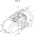
- Fig. 2 is an external perspective view of the distal end rigid portion 34
- Fig. 3 is a plan view (top view)
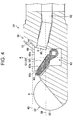
- Fig. 4 is a side sectional view.
- the distal end rigid portion 34 has a distal end rigid portion body (frame body) 36 that forms the outer wall and the inner partition wall thereof. Components disposed in the distal end rigid portion 34 are disposed and held in housing portions (housing chambers) that are defined by the distal end rigid portion body 36.
- a part of the distal end rigid portion body 36 is removable as a separated block.
- the components can be installed in a predetermined housing portion in a state in which the separated block is removed. After installing the components in the housing portions, by attaching the separate block to the distal end rigid portion body 36, the components can be disposed and held in the housing portions and fixed to the distal end rigid portion 34.
- the distal end rigid portion body 36 is made of an insulating material having insulating properties, which is, for example, a resin material that is a plastic or the like, such as a methacrylate resin or polycarbonate.
- the distal end rigid portion 34 is composed of a base member 40 that is included in the distal end rigid portion body 36, and an extension portion 42 that extends from the base member 40 toward the distal end side and holds an ultrasonic transducer 50.
- the ultrasonic transducer 50 of a convex-type is disposed.
- the ultrasonic transducer 50 has, on the upper side thereof, an ultrasound transmitting/receiving surface 52 that is formed by arranging ultrasonic vibrators, for transmitting and receiving ultrasound, in a curved shape in the direction of an axis 38 of the distal end rigid portion 34.
- the ultrasonic transducer 50 obtains data for generating an ultrasound image of a body tissue.
- the direction of the axis 38 of the distal end rigid portion 34 is the direction of a line that coincides with or is parallel to the longitudinal axis of the insertion section 12 of Fig. 1 .
- the number of ultrasonic vibrators is not limited and may be one; or two or more ultrasonic vibrators may be disposed.
- the base member 40 has an observation window 44, illumination windows 46L and 46R, an air/water supply nozzle 48, an opening 58 for leading out a treatment tool, and a standing wall portion 68 disposed around the opening 58.
- the opening 58 is formed at the center of an opening forming surface 70 that is located on the extension portion 42 side of the base member 40. From the opening 58, a treatment tool is led out to an ultrasound scanning range of the ultrasonic transducer 50.
- the opening 58 is formed in the opening forming surface 70 so that an opening direction thereof is toward one side, in a first direction that is perpendicular to the axis 38 of the distal end rigid portion 34, of the erecting base housing portion 62 of the distal end rigid portion body 36.
- the opening 58 may be formed so that an opening direction thereof has a component toward the one side in the first direction and a component toward the distal end side in the direction of the axis 38 of the distal end rigid portion 34.
- the opening may be formed so as to be open upward (toward the one side in the first direction) toward the distal end of the distal end rigid portion 34.
- opening direction refers to a direction normal to a surface surrounded by the edge of the opening 58.
- one side in the first direction refers to a direction, as indicated by arrow A in Fig. 4 , that is perpendicular to the axis 38 of the distal end rigid portion 34 and in which the opening 58 of the erecting base housing portion 62 is formed.
- second direction refers to a direction, as indicated by arrow B in Fig.
- the one side in the first direction may be referred to as “up” and “upward”, and the other side in the first direction may be referred to as “down” and “downward”.
- the opening forming surface 70 is formed of a surface that has a normal component in the opening direction. In the first embodiment, the opening direction is toward the one side in the first direction, and the opening-forming surface is parallel to the axis 38 of the distal end rigid portion 34. The opening-forming surface may be inclined downward (the other side in the first direction) toward the distal end side of the distal end rigid portion 34.
- the opening 58 is a portion through which a treatment tool is led out from the erecting base housing portion 62 via an erecting base 60 (described below).
- the distance between the ultrasonic transducer 50 and the opening 58 can be reduced. Accordingly, it is possible to reduce the distance from a position of a treatment tool that has just been led out from the opening 58 to a treatment target position to be treated with the treatment tool. As a result, horizontal displacement of the treatment tool can be reduced, and the treatment tool can be inserted to a target position.
- the standing wall portion 68 is formed around the opening 58. With the standing wall portion 68, horizontal displacement of a treatment tool that is led out from the opening 58 can be prevented, and treatment of a target position can be stably performed by using the treatment tool. It is sufficient that the standing wall portion 68 can prevent horizontal displacement of a treatment tool, and it is not necessary that the standing wall portion 68 be formed around the entirety of the opening 58. To be specific, preferably, the standing wall portion 68 is formed so as to stand upward from both sides of the direction in which the treatment tool is led out from the opening 58. In the first embodiment, the standing wall portion 68 stands on the entirety of the opening forming surface 70. The opening forming surface 70 and the standing wall portion 68 may be integrally formed.
- the distal end rigid portion body 36 has light-guiding recessed wall portions 76L and 76R, where left-side and right-side portions of an opening-forming surface portion 74 of the opening forming surface 70 are cut off diagonally downward.
- the light-guiding recessed wall portions 76L and 76R need not be cut off diagonally downward, and may be cut off in the vertical direction or may be cut off diagonally forward.
- the observation window 44 is disposed in the observation means forming surface 72 located on the proximal end side of the opening forming surface 70. Inside of the observation means forming surface 72, an imaging system unit, in which an image-forming optical system and a solid-state imaging element of an imaging unit are integrally assembled, is disposed. Thus, light from a subject in the field of view of the image-capturing portion enters through the observation window 44, a subject image is formed by the image-forming optical system, and the subject image is captured as an observation image by the solid-state imaging element.
- the observation means forming surface 72 is formed of a surface that has a normal component toward the distal end side in the direction of the axis 38 of the distal end rigid portion 34.
- the observation means forming surface 72 is formed as an inclined surface that is inclined upward toward the proximal end side of the distal end rigid portion body 36.
- the observation means forming surface 72 may be formed of a perpendicular surface that is perpendicular to the direction of the axis 38 of the distal end rigid portion 34.
- the illumination windows 46L and 46R are formed in the observation means forming surface 72 on both sides of the observation window 44.
- a light emitting portion of the illumination portion is disposed inside of the observation means forming surface 72. From the light emitting portion, illumination light that is transmitted from the light source device connected to the universal cord 14 through the light guide is emitted. The illumination light illuminates a subject in the field of view of the image-capturing portion through the illumination windows 46L and 46R.
- the air/water supply nozzle 48 is formed at the observation means forming surface 72.
- the air/water supply nozzle 48 ejects a cleaning liquid, water, air, or the like (hereinafter, referred to as "cleaning liquid or the like") toward the observation window 44 to perform cleaning or the like of the observation window 44.
- the observation means forming surface 72 has a deflecting portion 78 at a position that is opposite the air/water supply nozzle 48 with the observation window 44 therebetween.
- the deflecting portion 78 is disposed so as to protrude from the observation means forming surface 72.
- the deflecting portion 78 may be integrally formed with the observation means forming surface 72 or may be fixed as an independent portion.
- a cleaning liquid or the like that is ejected from the air/water supply nozzle 48 toward the observation window 44 collides with the deflecting portion 78.
- the cleaning liquid or the like that has collided with the deflecting portion 78 is deflected toward the opening 58, and is supplied to the opening 58. Thus, cleaning or the like of the inside of the opening 58 is performed.
- the shape of the deflecting portion 78 is not particularly limited, as long as the deflecting portion 78 can deflect the cleaning liquid or the like that has passed the observation window 44 toward the opening 58.
- the deflecting portion 78 may be formed of two surfaces 78A and 78B, which are flat surfaces that are perpendicular to each other.
- the deflecting portion 78 may be formed of a surface that has a curved shape, such as an arc shape, an elliptical arc shape, or a parabolic shape.
- the erecting base housing portion 62 which is disposed continuously with the opening 58, is formed in the opening 58.
- the treatment tool lead-out port 80 of a treatment tool insertion channel 82 is disposed on the proximal end side of the erecting base housing portion 62.
- the treatment tool lead-out port 80 communicates with the treatment tool insertion channel 82 extending through the insertion section 12. A treatment tool inserted from the treatment tool insertion opening 24 of the operation unit 10 (see Fig. 1 ) is led out from the treatment tool lead-out port 80 to the erecting base housing portion 62.
- the erecting base (treatment-tool erecting base) 60 is disposed at a position in the erecting base housing portion 62 in front of the treatment tool lead-out port 80.
- the erecting base 60 is made of a metal material such as stainless steel, and has, at an upper side thereof, a guide surface 60a that has a concave shape that is curved upward from the proximal end side toward the distal end side of the distal end rigid portion body 36.
- a treatment tool led out from the treatment tool lead-out port 80 is bent upward along the guide surface 60a with respect to the direction of the axis 38 of the distal end rigid portion 34 (the longitudinal direction of the insertion section 12) and is led to the outside from the opening 58 on the upper side of the erecting base housing portion 62 and the edge of the standing wall portion 68.
- the erecting base 60 can be erected by operating the erecting operation lever 18 of the operation unit 10.
- the lead-out direction (lead-out angle) of a treatment tool that is led out from the opening 58 can be adjusted by erecting the erecting base 60 and adjusting the erection angle from a prostrate state.
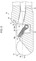
- Fig. 5 is a side sectional view of an erecting base 61 of a distal end rigid portion according to a modification.
- the erecting base 60 according to the first embodiment which is illustrated in Fig. 4
- a distal end part of the erecting base 60 protrudes from a front edge 68b of the standing wall portion 68.
- the insertion section 12 can be smoothly inserted into a human body.
- the treatment tool insertion channel 82 is coupled also to a suction channel (not shown).
- a suction channel By operating the suction button 22 of the operation unit 10, suction of a bodily fluid or the like through the opening 58 can be also performed.
- the position of an end portion of the upper edge 68a of the standing wall portion 68 that is furthest toward the one side in the first direction indicated by arrow A (the up-down direction in Fig. 4 ) is defined as a one-side wall upper end position Q1
- the position of the observation window 44 in the first direction (the up-down direction in Fig. 4 ) is located on the one side in the first direction relative to the one-side wall upper end position Q1. That is, an axis 45 of the observation window, which extends from the center position of the observation window 44 parallel to the axis 38 of the distal end rigid portion 34, is located above the position of the upper edge 68a.
- a treatment tool is led to the outside from the upper edge 68a or the front edge 68b of the standing wall portion 68.
- the position of the vertex that is located at an end portion of the ultrasound transmitting/receiving surface 52 of the ultrasonic transducer 50 that is furthest toward the one side in the first direction is defined as a vertex position P.
- the position of an end portion of the upper edge 68a of the standing wall portion 68 that is furthest toward the other side in the first direction is defined as an other-side wall upper end position Q2.
- the vertex position P is identical to the other-side wall upper end position Q2 or is located on the one side in the first direction relative to the other-side wall upper end position Q2.
- the one-side wall upper end position Q1 is identical to the other-side wall upper end position Q2.
- the position of the lowest end of the upper edge 68a is defined as the other-side wall upper end position Q2.
- the treatment tool can be led out so as to be close to the ultrasonic transducer 50. Accordingly, the treatment tool can be reliably inserted to a position where ultrasonic observation is performed by using the ultrasonic transducer 50.
- the vertex position P is identical to the lead-out port position R or is located on the one side in the first direction relative to (below) the lead-out port position R.
- a treatment tool passes through the treatment tool insertion channel 82 and is led out diagonally upward from the opening 58, which opens upward. Accordingly, by locating the treatment tool lead-out port 80 below the ultrasonic transducer 50, the treatment tool can be led out to the vicinity of the ultrasonic transducer 50.
- the lead-out port position R is preferably the center position in the treatment tool lead-out port 80 (see Fig. 4 ), and more preferably, is filled with the position of an end portion (upper end position) of the treatment tool lead-out port 80 on the one side in the first direction.
- the observation window 44 is disposed offset from the erecting base 60 in the second direction indicated by arrow B.
- the clause "the observation window 44 is disposed offset from the erecting base 60 in the second direction” means that, as illustrated in Fig. 3 , in a top view, a center line 44A of the observation window 44 is displaced from a center line 60A of the erecting base 60 in the second direction indicated by arrow B.
- Fig. 6 illustrates a state in which a stent is inserted into a body cavity wall.
- Fig. 7 illustrates an optical image of the inserted state, which is captured through the observation window.
- an insertion point 96 can be observed with an optical image of the observation window 44. Accordingly, whether the proximal end side of the stent 90 is exposed can be readily checked from the insertion point 96, and, compared with existing technology, a step of changing the field of view of the observation window 44 by moving the insertion section 12 for checking can be reduced.
- the ultrasound transmitting/receiving surface 52 of the ultrasonic transducer 50 which is hidden by the body cavity wall 94, is not shown.
- Fig. 8 is an external perspective view of a distal end rigid portion 134 of an insertion section of an ultrasonic endoscope according to a second embodiment.
- the distal end rigid portion 134 according to the second embodiment differs from the distal end rigid portion 34 according to the first embodiment in that the distal end rigid portion 134 does not have a standing wall portion and a light-guiding recessed wall portion.
- elements that are the same those of the first embodiment will be denoted by the same numerals and description of such elements may be omitted.
- a treatment tool led out from the opening 158 can be placed within the field of view of the observation window 44.
- the axis 145 of the observation window 44 is a line extending from the center position of the observation window 44 toward the distal end side, and is a line that is parallel to an axis 138 of the distal end rigid portion 134.
- the erecting base 60 emerges from the opening 158.
- the erecting base 60 can be checked in the field of view of the observation window 44, and a treatment tool can be led out to a target position by guiding the treatment tool with the erecting base 60.
- the vertex position is identical to the other-side opening position or is located on the one side in the first direction relative to (above) the other-side opening position.
- Fig. 9 is an external perspective view of a distal end rigid portion 135 of an insertion section of an ultrasonic endoscope according to the second embodiment
- Fig. 10 is a side sectional view.
- the distal end rigid portion 135 illustrated in Figs. 9 and 10 has an opening 159 whose opening direction has a component toward the one end side in the first direction and a component toward the distal end side in the direction of the axis 138 of the distal end rigid portion 135.
- the distal end rigid portion 135 differs from the distal end rigid portion 134 illustrated in Fig. 8 in that an opening forming surface 171 is an inclined surface that is inclined toward the one side in the first direction (upward) toward the proximal end side of the distal end rigid portion 135.
- the position of the opening 159 is located on the distal end side of the distal end rigid portion 135 relative to the observation window 44.
- a one-side opening position U1 which is a position of an end portion of the opening 159 that is furthest toward the one side in the first direction, is located below the axis 145 of the observation window 44.
- the vertex position P is identical to the other-side opening position U1 or is located on the one side in the first direction relative to (above) the other-side opening position U1.
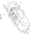
- Fig. 11 is an external perspective view of a distal end rigid portion 234 of an insertion section of an ultrasonic endoscope according to a third embodiment.
- Fig. 12 illustrates a state in which the distal end rigid portion 234 is made to closely contact the body cavity wall 94.
- the distal end rigid portion 234 of the ultrasonic endoscope according to the third embodiment differs from the distal end rigid portion 34 according to the first embodiment in that the position where a standing wall portion 268 is formed is only on the proximal end side of an opening 258. Even when the standing wall portion 268 is disposed only on the proximal end side of the opening 258, an effect of preventing horizontal displacement can be obtained.
- the distal end rigid portion 234 of the ultrasonic endoscope by locating an upper edge 268a of the standing wall portion 268 on the distal end side relative the observation window 44 and by locating, in the first direction indicated by arrow A in Fig. 11 , a one-side wall upper end position of the standing wall portion 268 below an axis 245 of the observation window 44, a treatment tool led out from the standing wall portion 268 of a distal end rigid portion body 236 can be placed within the field of view of the observation window 44.
- the axis 245 of the observation window 44 is a line extending from the center position of the observation window 44 toward the distal end side, and is a line that is parallel to an axis 238 of the distal end rigid portion 234.
- the body cavity wall (tissue) 94 can be made to closely contact even the proximal end side of the ultrasound transmitting/receiving surface 52 of the ultrasonic transducer 50.
- the distance between the opening 258 and the body cavity wall 94 can be reduced. Therefore, the position of a treatment tool led out from the opening 258 can be prevented from becoming displaced by a large distance, and treatment can be performed at a target position.
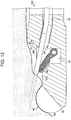
- Fig. 13 is a side sectional view of a distal end rigid portion 334 of an ultrasonic endoscope according to a fourth embodiment.
- a one-side opening position U1 of an opening 358 in the first direction indicated by arrow A in Fig. 13 is located on the one side in the first direction relative to (above) the position of a vertex (the vertex position P) of the ultrasound transmitting/receiving surface 52 of the ultrasonic transducer 50 that is located at an end portion that is furthest toward the one side in the first direction.
- a lead-out port position R of a treatment tool lead-out port 380 is located on the one side in the first direction relative to (above) the one-side opening position U1 of the opening 358.
- treatment can be performed by using a treatment tool while observing the treatment tool led out from the opening 58 in the field of view of the observation window 44.
- Fig. 14 is a sectional view of a modification of a distal end rigid portion 434 of an insertion section of an ultrasonic endoscope according to a modification of the fourth embodiment.
- the distal end rigid portion 434 illustrated in Fig. 14 differs from the distal end rigid portion 334 illustrated in Fig. 13 in that an other-side opening position U2 of an opening 458 is located at a position identical to the position of a vertex (the vertex position P) of the ultrasound transmitting/receiving surface 52 of the ultrasonic transducer 50 at an end portion that is furthest toward the one side in the first direction indicated by arrow A in Fig. 14 .
- the other-side opening position U2 of the opening 458 may be identical to the vertex position P of the ultrasound transmitting/receiving surface 52 or is located below the vertex position P.
Landscapes
- Health & Medical Sciences (AREA)
- Life Sciences & Earth Sciences (AREA)
- Surgery (AREA)
- General Health & Medical Sciences (AREA)
- Medical Informatics (AREA)
- Veterinary Medicine (AREA)
- Pathology (AREA)
- Radiology & Medical Imaging (AREA)
- Biophysics (AREA)
- Engineering & Computer Science (AREA)
- Biomedical Technology (AREA)
- Heart & Thoracic Surgery (AREA)
- Nuclear Medicine, Radiotherapy & Molecular Imaging (AREA)
- Molecular Biology (AREA)
- Animal Behavior & Ethology (AREA)
- Physics & Mathematics (AREA)
- Public Health (AREA)
- Optics & Photonics (AREA)
- Gynecology & Obstetrics (AREA)
- Ultra Sonic Daignosis Equipment (AREA)
- Endoscopes (AREA)
Abstract
Description
- The present invention relates to an ultrasonic endoscope, and, in particular to an ultrasonic endoscope including a treatment-tool erecting base for erecting a treatment tool that is led out from an opening formed in a distal end rigid portion of an endoscope insertion section.
- Some existing ultrasonic endoscopes known to date include an erecting base in a distal end part of an insertion section that is inserted into a body cavity. Such an ultrasonic endoscope can erect a treatment tool, which is inserted into a treatment tool insertion channel and led out from a treatment tool lead-out portion at the distal end part, and can also adjust the lead-out direction of the treatment tool by changing the erection angle of the erecting base.
- For example,
JP2005-287593A - However, in the ultrasonic endoscope described in
JP2005-287593A - The present invention has been made under such circumstances, and an object of the present invention is to provide an ultrasonic endoscope that can observe even a proximal end portion side of a treatment tool in the field of view of an observation window.
- To achieve the object, the present invention provides an ultrasonic endoscope including: a distal end rigid portion that is located at a distal end of an endoscope insertion section; an ultrasonic transducer that is disposed in the distal end rigid portion; a treatment tool lead-out portion that is disposed on a proximal end side of the ultrasonic transducer and that comprises an erecting base housing portion that has an opening whose opening direction is toward one side in a first direction that is perpendicular to an axial direction of the distal end rigid portion or whose opening direction is a direction that has a component toward the one side in the first direction and a component toward a distal end side in the axial direction of the distal end rigid portion, an opening forming surface in which the opening is formed and that has a normal component in the opening direction, a treatment tool lead-out port that communicates with an inside of the erecting base housing portion and from which a treatment tool is led out, and a treatment-tool erecting base that is disposed in the inside of the erecting base housing portion and that changes a lead-out direction of the treatment tool led out from the treatment tool lead-out port; and an observation window that is disposed on a proximal end side of the opening forming surface and that is disposed in an observation means forming surface that has a normal component toward the distal end side in the axial direction of the distal end rigid portion. When a position of an end portion of the opening that is furthest toward the one side in the first direction is defined as a one-side opening position, a position of the observation window in the first direction is located on the one side in the first direction relative to the one-side opening position.
- If the opening is located on the proximal end side of the observation window as in existing ultrasonic endoscopes, only a part of a treatment tool on the distal end side relative to the observation window is within the field of view of the observation window, and it is not possible to check through the observation window depending on a treatment target position to be treated with the treatment tool. In the present invention, the opening for leading out a treatment tool is disposed on the distal end side relative to the observation window. Moreover, the position of the observation window in the first direction is located on the one side in the first direction relative to the one-side opening position of the opening. Thus, a blind area where a treatment tool led out from the opening is not within the field of view of the observation window can be reduced. Accordingly, treatment can be performed while checking through the observation window, and treatment can be reliably performed at a target position.
- According to another aspect of the present invention, preferably, the ultrasonic transducer has an ultrasound transmitting/receiving surface that is formed in a curved shape in the axial direction of the distal end rigid portion.
- The present invention can be appropriately used for a convex-type ultrasonic endoscope in which the ultrasound transmitting/receiving surface of the ultrasonic transducer is formed in a curved shape in the axial direction of the distal end rigid portion.
- According to another aspect of the present invention, preferably, the ultrasound transmitting/receiving surface has a vertex that is located at an end portion thereof that is furthest toward the one side in the first direction; and, when a position of the vertex in the first direction is defined as a vertex position and a position of an end portion of the opening that is furthest toward the other side in the first direction is defined as an other-side opening position, the vertex position is identical to the other-side opening position or is located on the one side in the first direction relative to the other-side opening position.
- This aspect defines the positions of the opening and the ultrasonic transducer. By locating the vertex position of the ultrasound transmitting/receiving surface in the first direction to be identical to the other-side opening position or on the one side in the first direction relative to the other-side opening position, a treatment tool led out from the opening can be made to be closer to the ultrasonic transducer. By making also the treatment tool be closer to the ultrasonic transducer, a position observed by the ultrasonic observation position can be treated with a treatment tool.
- According to another aspect of the present invention, preferably, when a position of the treatment tool lead-out port in the first direction is defined as a lead-out port position, the vertex position is identical to the lead-out port position or is located on the one side in the first direction relative to the lead-out port position.
- This aspect defines the positions of the treatment tool lead-out port and the ultrasonic transducer. A treatment tool passes through a treatment tool insertion channel formed in the endoscope insertion section and is led out from the opening formed on one side in the first direction. Accordingly, by locating the vertex position of the ultrasound transmitting/receiving surface in the first direction to be identical to the lead-out port position or on the one side in the first direction relative to the lead-out port position, a treatment tool can be guided to the vicinity of the ultrasonic transducer. Thus, treatment with a treatment tool can be performed at a position observed by ultrasonic observation.
- According to another aspect of the present invention, preferably, the ultrasonic endoscope has a standing wall portion around the opening, the standing wall portion standing from the opening; and, when a position of an end portion of an upper edge of the standing wall portion that is furthest toward the one side in the first direction is defined as a one-side wall upper end position, the position of the observation window in the first direction is located on the one side in the first direction relative to the one-side wall upper end position.
- With this aspect, because the standing wall portion is provided around the opening, horizontal displacement of a treatment tool led out from the opening can be prevented, and treatment with the treatment tool can be reliably performed at a target position. Moreover, because the position of the observation window is on the one side in the first direction relative to the one-side wall upper end position, treatment at a target position can be performed while checking a treatment tool led out from the standing wall portion through the observation window.
- According to another aspect of the present invention, preferably, the standing wall portion is disposed only on the proximal end side of the opening.
- With this aspect, because the positon of the standing wall portion is on the proximal end side of the opening, a space can be formed between the ultrasonic transducer and the standing wall portion. Accordingly, even a proximal end side of the ultrasound transmitting/receiving surface of the ultrasonic transducer can be made to be in close contact with a body cavity wall (tissue), the distance between a treatment tool led out from the opening and the body cavity wall can be reduced, and the treatment tool can be more easily inserted to a target position.
- According to another aspect of the present invention, preferably, the ultrasonic transducer has an ultrasound transmitting/receiving surface that is formed in a curved shape in the axial direction of the distal end rigid portion.
- The present invention can be appropriately used for a convex-type ultrasonic endoscope in which the ultrasound transmitting/receiving surface of the ultrasonic transducer is formed in a curved shape in the axial direction of the distal end rigid portion.
- According to another aspect of the present invention, preferably, the ultrasound transmitting/receiving surface has a vertex that is located at an end portion thereof that is furthest toward the one side in the first direction; and, when a position of the vertex in the first direction is defined as a vertex position and a position of an end portion of an upper edge of the standing wall portion that is furthest toward the other side in the first direction is defined as an other-side wall upper end position, the vertex position is identical to the other-side wall upper end position or is located on the one side in the first direction relative to the other-side wall upper end position.
- This aspect defines the positions of the upper edge of the standing wall portion and the ultrasonic transducer when the standing wall portion is provided. By locating the vertex position of the ultrasound transmitting/receiving surface in the first direction to be identical to the other-side wall upper end position or on the one side in the first direction relative to the other-side wall upper end position, a treatment tool led out from the standing wall portion can be made closer to the ultrasonic transducer. Accordingly, treatment with a treatment tool can be performed at a position observed by the ultrasonic observation position.
- According to another aspect of the present invention, preferably, the observation window is disposed offset from the treatment-tool erecting base in a second direction that is perpendicular to the first direction.
- With this aspect, because the observation window is disposed offset from the treatment-tool erecting base in the second direction, when the treatment-tool erecting base is erected, blocking of the field of view of the observation window by the treatment tool and the treatment-tool erecting base can be prevented.
- According to another aspect of the present invention, preferably, the treatment-tool erecting base emerges from the opening forming surface.
- With this aspect, by causing the treatment-tool erecting base to emerge from the opening forming surface, the treatment-tool erecting base that emerges from the opening can be observed in the field of view of the observation window.
- According to another aspect of the present invention, preferably, the ultrasonic endoscope comprises, at the observation means forming surface, a nozzle that ejects a cleaning liquid toward the observation window and a deflection portion that deflects the cleaning liquid that has passed the observation window toward the opening.
- With this aspect, because cleaning of the observation window is performed by ejecting the cleaning liquid from the nozzle at the observation means forming surface and because the deflecting portion for deflecting the cleaning liquid toward the opening is provided, the cleaning liquid that has passed the observation window can be directed toward the opening, and the opening can be cleaned with the cleaning liquid.
- According to another aspect of the present invention, preferably, the observation means forming surface has an illumination portion, and both side portions of the opening forming surface have light-guiding recessed wall portions that suppress blocking of illumination light from the illumination portion.
- With this aspect, by providing the light-guiding recessed wall portions on both sides of the opening forming surface, nonuniform illumination from the illumination portion and generation of a shadowed region can be prevented, and therefore treatment with a treatment tool can be safely performed.
- With the ultrasonic endoscope according to the present invention, because the observation window is disposed on the proximal end side of the opening and the position of the observation window in the first direction is located on the one side in the first direction relative to the one-side opening position of the opening, a blind area where a treatment tool led out from the opening is not within the field of view of the observation window can be reduced. Thus, a treatment tool led out from the opening can be checked through the observation window, and treatment can be reliably performed at a target position.
-
-
Fig. 1 is an overall view of an ultrasonic endoscope according to the present invention; -
Fig. 2 is an external perspective view of a distal end rigid portion of an insertion section according to a first embodiment; -
Fig. 3 is an external plan view (top view) of the distal end rigid portion of the insertion section according to the first embodiment; -
Fig. 4 is a side sectional view of the distal end rigid portion of the insertion section according to the first embodiment; -
Fig. 5 is a side sectional view of an erecting base of a distal end rigid portion according to a modification; -
Fig. 6 illustrates a state in which a stent is inserted into a body cavity wall; -
Fig. 7 illustrates an optical image of the inserted state that is captured through an observation window; -
Fig. 8 is an external perspective view of a distal end rigid portion of an insertion section according to a second embodiment; -
Fig. 9 is an external perspective view of a distal end rigid portion of an insertion section according to a modification of the second embodiment; -
Fig. 10 is a side sectional view of a distal end rigid portion of an insertion section according to a modification of a fourth embodiment; -
Fig. 11 is an external perspective view of a distal end rigid portion of an insertion section according to a third embodiment; -
Fig. 12 illustrates a state in which the distal end rigid portion is made to closely contact a body cavity wall; -
Fig. 13 is a side sectional view of a distal end rigid portion of an insertion section according to a fourth embodiment; and -
Fig. 14 is a side sectional view of a distal end rigid portion of an insertion section according to a modification of the fourth embodiment. - Hereafter, an ultrasonic endoscope according to the present invention will be described with reference to the drawings.
-
Fig. 1 is an overall view of anultrasonic endoscope 1 to which the present invention is applied. - The ultrasonic endoscope 1 (hereafter, simply referred to as "the
endoscope 1") illustrated in the figure includes anoperation unit 10 that an operator grips to perform various operations, an insertion section (endoscope insertion section) 12 that is inserted into a body cavity of a patient, and auniversal cord 14 for connecting theendoscope 1 to system component devices (not shown) of an endoscope system, such as a processor device and a light source device. - The
operation unit 10 has various operation members that are operated by an operator, such as anangle knob 16, whose functions will be described below as necessary, an erectingoperation lever 18, an air/water supply button 20, and asuction button 22. - The
operation unit 10 has a treatment tool insertion opening 24 from which a treatment tool is inserted into a treatment tool insertion channel, which extends through theinsertion section 12. - The
insertion section 12 extends from a distal end of theoperation unit 10, and has a small-diameter elongated shape as a whole. - The
insertion section 12 is composed of asoft portion 30, a bendingportion 32, a distal endrigid portion 34, in order from the proximal end side toward the distal end side. - The
soft portion 30 occupies most part of theinsertion section 12 from the proximal end side, and has flexibility with which thesoft portion 30 can be bent in any directions. When theinsertion section 12 is inserted into the body cavity, thesoft portion 30 is bent along an insertion path into the body cavity. - The bending
portion 32 can be bent in the up-down direction and the left-right direction by rotating theangle knob 16 of theoperation unit 10. By bending the bendingportion 32, the distal endrigid portion 34 can be directed in a desired direction. - As described below in detail, the distal end
rigid portion 34 includes an image capturing portion and an illumination portion for capturing an observation image of the inside of a body cavity, an ultrasonic transducer for obtaining an ultrasound image, and a treatment tool lead-out portion for leading out a treatment tool inserted from the treatmenttool insertion opening 24. The treatment tool lead-out portion is composed of a treatment tool lead-outport 80, an erecting base housing portion, an erecting base, an opening, an opening forming surface, and the like. In the following description, an erectingbase housing portion 62 may be used synonymously with a treatment tool lead-out portion. - The
universal cord 14 contains an electric cable, a light guide, and a fluid tube. Theuniversal cord 14 includes a connector at an end portion thereof (not shown). By connecting the connector to predetermined system component devices of the endoscope system, such as a processor device and a light-source device, electric power, control signals, illumination light, liquid, gas, and the like that are necessary to operate theendoscope 1 are supplied from the system component devices to the endoscope; and data of an observation image obtained by the image-capturing portion and data of an ultrasound image obtained by the ultrasonic transducer are transmitted from theendoscope 1 to the system component devices. The observation image and the ultrasound image transmitted to the system component devices are displayed on a monitor, and an operator and the like can observe the images. - Next, the structure of the distal end
rigid portion 34 of theinsertion section 12 will be described.Fig. 2 is an external perspective view of the distal endrigid portion 34,Fig. 3 is a plan view (top view), andFig. 4 is a side sectional view. - The distal end
rigid portion 34 has a distal end rigid portion body (frame body) 36 that forms the outer wall and the inner partition wall thereof. Components disposed in the distal endrigid portion 34 are disposed and held in housing portions (housing chambers) that are defined by the distal endrigid portion body 36. - Although details are omitted, a part of the distal end
rigid portion body 36 is removable as a separated block. The components can be installed in a predetermined housing portion in a state in which the separated block is removed. After installing the components in the housing portions, by attaching the separate block to the distal endrigid portion body 36, the components can be disposed and held in the housing portions and fixed to the distal endrigid portion 34. - The distal end
rigid portion body 36 is made of an insulating material having insulating properties, which is, for example, a resin material that is a plastic or the like, such as a methacrylate resin or polycarbonate. - As illustrated in
Figs. 2 to 4 , the distal endrigid portion 34 is composed of abase member 40 that is included in the distal endrigid portion body 36, and anextension portion 42 that extends from thebase member 40 toward the distal end side and holds anultrasonic transducer 50. - In the
extension portion 42, theultrasonic transducer 50 of a convex-type is disposed. Theultrasonic transducer 50 has, on the upper side thereof, an ultrasound transmitting/receivingsurface 52 that is formed by arranging ultrasonic vibrators, for transmitting and receiving ultrasound, in a curved shape in the direction of anaxis 38 of the distal endrigid portion 34. Theultrasonic transducer 50 obtains data for generating an ultrasound image of a body tissue. Here, the direction of theaxis 38 of the distal endrigid portion 34 is the direction of a line that coincides with or is parallel to the longitudinal axis of theinsertion section 12 ofFig. 1 . The number of ultrasonic vibrators is not limited and may be one; or two or more ultrasonic vibrators may be disposed. - The
base member 40 has anobservation window 44,illumination windows water supply nozzle 48, anopening 58 for leading out a treatment tool, and a standingwall portion 68 disposed around theopening 58. - The
opening 58 is formed at the center of anopening forming surface 70 that is located on theextension portion 42 side of thebase member 40. From theopening 58, a treatment tool is led out to an ultrasound scanning range of theultrasonic transducer 50. Theopening 58 is formed in theopening forming surface 70 so that an opening direction thereof is toward one side, in a first direction that is perpendicular to theaxis 38 of the distal endrigid portion 34, of the erectingbase housing portion 62 of the distal endrigid portion body 36. Theopening 58 may be formed so that an opening direction thereof has a component toward the one side in the first direction and a component toward the distal end side in the direction of theaxis 38 of the distal endrigid portion 34. That is, the opening may be formed so as to be open upward (toward the one side in the first direction) toward the distal end of the distal endrigid portion 34. Here, the term "opening direction" refers to a direction normal to a surface surrounded by the edge of theopening 58. In the present description, the phrase "one side in the first direction" refers to a direction, as indicated by arrow A inFig. 4 , that is perpendicular to theaxis 38 of the distal endrigid portion 34 and in which theopening 58 of the erectingbase housing portion 62 is formed. The term "second direction" refers to a direction, as indicated by arrow B inFig. 2 , that is perpendicular to theaxis 38 of the distal endrigid portion 34 and to the first direction indicated by arrow A. In the present description, the one side in the first direction may be referred to as "up" and "upward", and the other side in the first direction may be referred to as "down" and "downward". - A treatment tool is inserted from the treatment
tool insertion opening 24 of theoperation unit 10. Theopening forming surface 70 is formed of a surface that has a normal component in the opening direction. In the first embodiment, the opening direction is toward the one side in the first direction, and the opening-forming surface is parallel to theaxis 38 of the distal endrigid portion 34. The opening-forming surface may be inclined downward (the other side in the first direction) toward the distal end side of the distal endrigid portion 34. Theopening 58 is a portion through which a treatment tool is led out from the erectingbase housing portion 62 via an erecting base 60 (described below). - By locating the position of the
opening 58 on the proximal end side of theultrasonic transducer 50 and on the distal end side relative to an observation means formingsurface 72 as described below, the distance between theultrasonic transducer 50 and theopening 58 can be reduced. Accordingly, it is possible to reduce the distance from a position of a treatment tool that has just been led out from theopening 58 to a treatment target position to be treated with the treatment tool. As a result, horizontal displacement of the treatment tool can be reduced, and the treatment tool can be inserted to a target position. - The standing
wall portion 68 is formed around theopening 58. With the standingwall portion 68, horizontal displacement of a treatment tool that is led out from theopening 58 can be prevented, and treatment of a target position can be stably performed by using the treatment tool. It is sufficient that the standingwall portion 68 can prevent horizontal displacement of a treatment tool, and it is not necessary that the standingwall portion 68 be formed around the entirety of theopening 58. To be specific, preferably, the standingwall portion 68 is formed so as to stand upward from both sides of the direction in which the treatment tool is led out from theopening 58. In the first embodiment, the standingwall portion 68 stands on the entirety of theopening forming surface 70. Theopening forming surface 70 and the standingwall portion 68 may be integrally formed. - The distal end
rigid portion body 36 has light-guiding recessedwall portions surface portion 74 of theopening forming surface 70 are cut off diagonally downward. By forming the light-guiding recessedwall portions illumination windows wall portions - The
observation window 44 is disposed in the observation means formingsurface 72 located on the proximal end side of theopening forming surface 70. Inside of the observation means formingsurface 72, an imaging system unit, in which an image-forming optical system and a solid-state imaging element of an imaging unit are integrally assembled, is disposed. Thus, light from a subject in the field of view of the image-capturing portion enters through theobservation window 44, a subject image is formed by the image-forming optical system, and the subject image is captured as an observation image by the solid-state imaging element. The observation means formingsurface 72 is formed of a surface that has a normal component toward the distal end side in the direction of theaxis 38 of the distal endrigid portion 34. In the first embodiment, the observation means formingsurface 72 is formed as an inclined surface that is inclined upward toward the proximal end side of the distal endrigid portion body 36. By forming the observation means formingsurface 72 as a surface having a normal component toward the distal end side and by forming theobservation window 44, a treatment tool that is led out from the opening can be checked through theobservation window 44. The observation means formingsurface 72 may be formed of a perpendicular surface that is perpendicular to the direction of theaxis 38 of the distal endrigid portion 34. - The
illumination windows surface 72 on both sides of theobservation window 44. A light emitting portion of the illumination portion is disposed inside of the observation means formingsurface 72. From the light emitting portion, illumination light that is transmitted from the light source device connected to theuniversal cord 14 through the light guide is emitted. The illumination light illuminates a subject in the field of view of the image-capturing portion through theillumination windows - The air/
water supply nozzle 48 is formed at the observation means formingsurface 72. When the air/water supply button 20 of theoperation unit 10 is operated, the air/water supply nozzle 48 ejects a cleaning liquid, water, air, or the like (hereinafter, referred to as "cleaning liquid or the like") toward theobservation window 44 to perform cleaning or the like of theobservation window 44. - The observation means forming
surface 72 has a deflectingportion 78 at a position that is opposite the air/water supply nozzle 48 with theobservation window 44 therebetween. The deflectingportion 78 is disposed so as to protrude from the observation means formingsurface 72. The deflectingportion 78 may be integrally formed with the observation means formingsurface 72 or may be fixed as an independent portion. A cleaning liquid or the like that is ejected from the air/water supply nozzle 48 toward theobservation window 44 collides with the deflectingportion 78. The cleaning liquid or the like that has collided with the deflectingportion 78 is deflected toward theopening 58, and is supplied to theopening 58. Thus, cleaning or the like of the inside of theopening 58 is performed. - The shape of the deflecting
portion 78 is not particularly limited, as long as the deflectingportion 78 can deflect the cleaning liquid or the like that has passed theobservation window 44 toward theopening 58. As illustrated inFigs. 2 and3 , the deflectingportion 78 may be formed of twosurfaces portion 78 may be formed of a surface that has a curved shape, such as an arc shape, an elliptical arc shape, or a parabolic shape. - The erecting
base housing portion 62, which is disposed continuously with theopening 58, is formed in theopening 58. The treatment tool lead-outport 80 of a treatmenttool insertion channel 82 is disposed on the proximal end side of the erectingbase housing portion 62. - The treatment tool lead-out
port 80 communicates with the treatmenttool insertion channel 82 extending through theinsertion section 12. A treatment tool inserted from the treatmenttool insertion opening 24 of the operation unit 10 (seeFig. 1 ) is led out from the treatment tool lead-outport 80 to the erectingbase housing portion 62. - The erecting base (treatment-tool erecting base) 60 is disposed at a position in the erecting
base housing portion 62 in front of the treatment tool lead-outport 80. - The erecting
base 60 is made of a metal material such as stainless steel, and has, at an upper side thereof, aguide surface 60a that has a concave shape that is curved upward from the proximal end side toward the distal end side of the distal endrigid portion body 36. A treatment tool led out from the treatment tool lead-outport 80 is bent upward along theguide surface 60a with respect to the direction of theaxis 38 of the distal end rigid portion 34 (the longitudinal direction of the insertion section 12) and is led to the outside from theopening 58 on the upper side of the erectingbase housing portion 62 and the edge of the standingwall portion 68. - The erecting
base 60 can be erected by operating the erectingoperation lever 18 of theoperation unit 10. The lead-out direction (lead-out angle) of a treatment tool that is led out from theopening 58 can be adjusted by erecting the erectingbase 60 and adjusting the erection angle from a prostrate state. -
Fig. 5 is a side sectional view of an erectingbase 61 of a distal end rigid portion according to a modification. With the erectingbase 60 according to the first embodiment, which is illustrated inFig. 4 , when the erectingbase 60 is in a prostrate position (a fully lowered state), a distal end part of the erectingbase 60 protrudes from afront edge 68b of the standingwall portion 68. In contrast, when the erectingbase 61 illustrated inFig. 5 is in a fully lowered state, the distal end part of the erectingbase 61 does not protrude from the standingwall portion 68, and the entirety of the erectingbase 61 is disposed in the erectingbase housing portion 62. With a structure such that the erectingbase 61 is disposed in the erectingbase housing portion 62 in the fully lowered state, theinsertion section 12 can be smoothly inserted into a human body. - The treatment
tool insertion channel 82 is coupled also to a suction channel (not shown). By operating thesuction button 22 of theoperation unit 10, suction of a bodily fluid or the like through theopening 58 can be also performed. - Next, the positional relationship among the opening 58 of the distal end
rigid portion body 36, anupper edge 68a of the standingwall portion 68, theobservation window 44, and theultrasonic transducer 50 will be described. - In the present embodiment, in the distal end
rigid portion body 36, when the position of an end portion of theupper edge 68a of the standingwall portion 68 that is furthest toward the one side in the first direction indicated by arrow A (the up-down direction inFig. 4 ) is defined as a one-side wall upper end position Q1, the position of theobservation window 44 in the first direction (the up-down direction inFig. 4 ) is located on the one side in the first direction relative to the one-side wall upper end position Q1. That is, anaxis 45 of the observation window, which extends from the center position of theobservation window 44 parallel to theaxis 38 of the distal endrigid portion 34, is located above the position of theupper edge 68a. When the standingwall portion 68 is provided, a treatment tool is led to the outside from theupper edge 68a or thefront edge 68b of the standingwall portion 68. By locating theupper edge 68a of the standingwall portion 68 below theobservation window 44 in this way, a treatment tool led out from the standingwall portion 68 can be reliably placed within the field of view of theobservation window 44, the treatment tool can be guided to a target position, and the accuracy of positioning the treatment tool can be improved. - In the first direction of the distal end
rigid portion body 36 indicated by arrow A inFig. 4 , the position of the vertex that is located at an end portion of the ultrasound transmitting/receivingsurface 52 of theultrasonic transducer 50 that is furthest toward the one side in the first direction is defined as a vertex position P. The position of an end portion of theupper edge 68a of the standingwall portion 68 that is furthest toward the other side in the first direction is defined as an other-side wall upper end position Q2. Then, in the first direction, the vertex position P is identical to the other-side wall upper end position Q2 or is located on the one side in the first direction relative to the other-side wall upper end position Q2. InFig. 4 , because theupper edge 68a is parallel to the direction of theaxis 38 of the distal endrigid portion 34, the one-side wall upper end position Q1 is identical to the other-side wall upper end position Q2. When theupper edge 68a is diagonally formed, the position of the lowest end of theupper edge 68a is defined as the other-side wall upper end position Q2. By disposing theupper edge 68a of the standingwall portion 68 and theultrasonic transducer 50 so that the vertex position P is identical to the other-side wall upper end position Q2 or is located on the one side in the first direction relative to the other-side wall upper end position Q2, when a treatment tool that has passed through the treatmenttool insertion channel 82 is led out diagonally upward from theupper edge 68a or thefront edge 68b of the standingwall portion 68, the treatment tool can be led out so as to be close to theultrasonic transducer 50. Accordingly, the treatment tool can be reliably inserted to a position where ultrasonic observation is performed by using theultrasonic transducer 50. - When the position of the treatment tool lead-out
port 80 in the first direction of the distal endrigid portion body 36 indicated by arrow A inFig. 4 is defined as a lead-out port position R, the vertex position P is identical to the lead-out port position R or is located on the one side in the first direction relative to (below) the lead-out port position R. A treatment tool passes through the treatmenttool insertion channel 82 and is led out diagonally upward from theopening 58, which opens upward. Accordingly, by locating the treatment tool lead-outport 80 below theultrasonic transducer 50, the treatment tool can be led out to the vicinity of theultrasonic transducer 50. The lead-out port position R is preferably the center position in the treatment tool lead-out port 80 (seeFig. 4 ), and more preferably, is filled with the position of an end portion (upper end position) of the treatment tool lead-outport 80 on the one side in the first direction. - As illustrated in
Fig. 3 , preferably, theobservation window 44 is disposed offset from the erectingbase 60 in the second direction indicated by arrow B. Here, the clause "theobservation window 44 is disposed offset from the erectingbase 60 in the second direction" means that, as illustrated inFig. 3 , in a top view, acenter line 44A of theobservation window 44 is displaced from acenter line 60A of the erectingbase 60 in the second direction indicated by arrow B. With such a structure, even in a state in which the erectingbase 60 is erected and a treatment tool is led out from the standingwall portion 68, blocking of the field of view of theobservation window 44 by the treatment tool and the erectingbase 60 can be prevented, and a treatment target position can be checked through theobservation window 44. - Next, as an example of treatment performed by using an ultrasonic endoscope according to the present embodiment, an example of placing a stent will be described.
Fig. 6 illustrates a state in which a stent is inserted into a body cavity wall.Fig. 7 illustrates an optical image of the inserted state, which is captured through the observation window. - With the present embodiment, as illustrated in
Figs. 6 and7 , in a state in which astent 90 is inserted into abody cavity wall 94, aninsertion point 96 can be observed with an optical image of theobservation window 44. Accordingly, whether the proximal end side of thestent 90 is exposed can be readily checked from theinsertion point 96, and, compared with existing technology, a step of changing the field of view of theobservation window 44 by moving theinsertion section 12 for checking can be reduced. InFig. 7 , the ultrasound transmitting/receivingsurface 52 of theultrasonic transducer 50, which is hidden by thebody cavity wall 94, is not shown. -
Fig. 8 is an external perspective view of a distal endrigid portion 134 of an insertion section of an ultrasonic endoscope according to a second embodiment. The distal endrigid portion 134 according to the second embodiment differs from the distal endrigid portion 34 according to the first embodiment in that the distal endrigid portion 134 does not have a standing wall portion and a light-guiding recessed wall portion. In embodiments described below, elements that are the same those of the first embodiment will be denoted by the same numerals and description of such elements may be omitted. - Even without a standing wall portion, in the positional relationship between an opening 158 from which a treatment tool is led to the outside and the
observation window 44, by locating the position of theopening 158 on the distal end side relative to theobservation window 44 in the distal endrigid portion 34 and locating, in the first direction indicated by arrow A inFig. 8 , a one-side opening position, which is the position of an end portion of the opening that is furthest toward the one-side in the first direction, below anaxis 145 of theobservation window 44, a treatment tool led out from theopening 158 can be placed within the field of view of theobservation window 44. Theaxis 145 of theobservation window 44 is a line extending from the center position of theobservation window 44 toward the distal end side, and is a line that is parallel to anaxis 138 of the distal endrigid portion 134. - In a case where a treatment tool is led out from the
opening 158 to the outside of a distal endrigid portion body 136, preferably, the erectingbase 60 emerges from theopening 158. By causing the erectingbase 60 to emerge from theopening 158, the erectingbase 60 can be checked in the field of view of theobservation window 44, and a treatment tool can be led out to a target position by guiding the treatment tool with the erectingbase 60. - In the first direction indicated by arrow A in
Fig. 8 , when the position of an end portion of theopening 158 that is furthest toward the other side in the first direction is defined as an other-side opening position, and the position of a vertex of the ultrasound transmitting/receivingsurface 52 of theultrasonic transducer 50 that is located furthest toward the one side in the first direction is defined as a vertex position, the vertex position is identical to the other-side opening position or is located on the one side in the first direction relative to (above) the other-side opening position. With such a structure, as with the first embodiment, a treatment tool can be led out so as to be close to theultrasonic transducer 50. -
Fig. 9 is an external perspective view of a distal endrigid portion 135 of an insertion section of an ultrasonic endoscope according to the second embodiment, andFig. 10 is a side sectional view. - The distal end
rigid portion 135 illustrated inFigs. 9 and10 has anopening 159 whose opening direction has a component toward the one end side in the first direction and a component toward the distal end side in the direction of theaxis 138 of the distal endrigid portion 135. The distal endrigid portion 135 differs from the distal endrigid portion 134 illustrated inFig. 8 in that anopening forming surface 171 is an inclined surface that is inclined toward the one side in the first direction (upward) toward the proximal end side of the distal endrigid portion 135. - Also in the case where the
opening forming surface 171 is an inclined surface, in the positional relationship between theopening 159 and theobservation window 44, the position of theopening 159 is located on the distal end side of the distal endrigid portion 135 relative to theobservation window 44. In the first direction indicated by arrow A inFig. 10 , a one-side opening position U1, which is a position of an end portion of theopening 159 that is furthest toward the one side in the first direction, is located below theaxis 145 of theobservation window 44. Thus, a treatment tool led out from theopening 159 can be placed within the field of view of theobservation window 44. - In the first direction indicated by arrow A in
Fig. 10 , when the position of an end portion of theopening 159 that is furthest toward the other side in the first direction is defined as an other-side opening position U2, and the position of a vertex of the ultrasound transmitting/receivingsurface 52 of theultrasonic transducer 50 that is located furthest toward the one side in the first direction is defined as a vertex position P, the vertex position P is identical to the other-side opening position U1 or is located on the one side in the first direction relative to (above) the other-side opening position U1. With such a structure, as with the first embodiment, a treatment tool can be led out so as to be close to theultrasonic transducer 50. -
Fig. 11 is an external perspective view of a distal endrigid portion 234 of an insertion section of an ultrasonic endoscope according to a third embodiment.Fig. 12 illustrates a state in which the distal endrigid portion 234 is made to closely contact thebody cavity wall 94. - As illustrated in
Fig. 11 , the distal endrigid portion 234 of the ultrasonic endoscope according to the third embodiment differs from the distal endrigid portion 34 according to the first embodiment in that the position where a standingwall portion 268 is formed is only on the proximal end side of anopening 258. Even when the standingwall portion 268 is disposed only on the proximal end side of theopening 258, an effect of preventing horizontal displacement can be obtained. - Also with the distal end
rigid portion 234 of the ultrasonic endoscope according to the third embodiment, by locating anupper edge 268a of the standingwall portion 268 on the distal end side relative theobservation window 44 and by locating, in the first direction indicated by arrow A inFig. 11 , a one-side wall upper end position of the standingwall portion 268 below anaxis 245 of theobservation window 44, a treatment tool led out from the standingwall portion 268 of a distal endrigid portion body 236 can be placed within the field of view of theobservation window 44. Theaxis 245 of theobservation window 44 is a line extending from the center position of theobservation window 44 toward the distal end side, and is a line that is parallel to anaxis 238 of the distal endrigid portion 234. - As illustrated in
Fig. 12 , by disposing the standingwall portion 268 only on the proximal end side of theopening 258, the body cavity wall (tissue) 94 can be made to closely contact even the proximal end side of the ultrasound transmitting/receivingsurface 52 of theultrasonic transducer 50. By making thebody cavity wall 94 closely contact the ultrasound transmitting/receivingsurface 52, the distance between theopening 258 and thebody cavity wall 94 can be reduced. Therefore, the position of a treatment tool led out from theopening 258 can be prevented from becoming displaced by a large distance, and treatment can be performed at a target position. -
Fig. 13 is a side sectional view of a distal endrigid portion 334 of an ultrasonic endoscope according to a fourth embodiment. - As illustrated in
Fig. 13 , in the distal endrigid portion 334 of the ultrasonic endoscope according to the fourth embodiment, a one-side opening position U1 of anopening 358 in the first direction indicated by arrow A inFig. 13 is located on the one side in the first direction relative to (above) the position of a vertex (the vertex position P) of the ultrasound transmitting/receivingsurface 52 of theultrasonic transducer 50 that is located at an end portion that is furthest toward the one side in the first direction. Moreover, a lead-out port position R of a treatment tool lead-outport 380 is located on the one side in the first direction relative to (above) the one-side opening position U1 of theopening 358. Also with the positional relationship illustrated inFig. 13 , by setting the positional relationship between theobservation window 44 and theopening 358 so that theopening 358 is on the distal end side relative to theobservation window 44 and the one-side opening position U1 is located below theobservation window 44, treatment can be performed by using a treatment tool while observing the treatment tool led out from theopening 58 in the field of view of theobservation window 44. -
Fig. 14 is a sectional view of a modification of a distal endrigid portion 434 of an insertion section of an ultrasonic endoscope according to a modification of the fourth embodiment. - The distal end
rigid portion 434 illustrated inFig. 14 differs from the distal endrigid portion 334 illustrated inFig. 13 in that an other-side opening position U2 of anopening 458 is located at a position identical to the position of a vertex (the vertex position P) of the ultrasound transmitting/receivingsurface 52 of theultrasonic transducer 50 at an end portion that is furthest toward the one side in the first direction indicated by arrow A inFig. 14 . The other-side opening position U2 of theopening 458 may be identical to the vertex position P of the ultrasound transmitting/receivingsurface 52 or is located below the vertex position P. By locating the other-side opening position U2 of theopening 458 at a position identical to or below the vertex position P of the ultrasound transmitting/receivingsurface 52, the outer size of the distal endrigid portion 434 can be reduced. -
- 1
- ultrasonic endoscope
- 10
- operation unit
- 12
- insertion section
- 14
- universal cord
- 16
- angle knob
- 18
- erecting operation lever
- 20
- air/water supply button
- 22
- suction button
- 24
- treatment-tool insertion opening
- 30
- soft portion
- 32
- bending portion
- 34, 134, 135, 234, 334, 434
- distal end rigid portion
- 36, 136, 236
- distal end rigid portion body (frame body)
- 38, 138, 238
- axis of distal end rigid portion
- 40
- base member
- 42
- extension portion
- 44
- observation window
- 44A
- center line of observation window
- 45, 145, 245
- axis of observation window
- 46L, 46R
- illumination window
- 48
- air/water supply nozzle
- 50
- ultrasonic transducer
- 52
- ultrasound transmitting/receiving surface
- 58, 158, 159, 258, 358, 458
- opening
- 60, 61
- erecting base (treatment-tool erecting base)
- 60A
- center line of erecting base
- 60a
- guide surface
- 62
- erecting base housing portion
- 68, 268
- standing wall portion
- 68a, 268a
- upper edge
- 68b
- front edge
- 70, 170, 171
- opening forming surface
- 72
- observation means forming surface
- 74
- opening-forming surface portion
- 76L, 76R
- light-guiding recessed wall portion
- 78, 78A, 78B
- deflecting portion
- 80, 380
- treatment tool lead-out port
- 82, 382
- treatment tool insertion channel
- 90
- stent
- 94
- body cavity wall (tissue)
- 96
- insertion point
Claims (12)
- An ultrasonic endoscope comprising:a distal end rigid portion that is located at a distal end of an endoscope insertion section;an ultrasonic transducer that is disposed in the distal end rigid portion;a treatment tool lead-out portion that is disposed on a proximal end side of the ultrasonic transducer and that comprisesan erecting base housing portion that has an opening whose opening direction is toward one side in a first direction that is perpendicular to an axial direction of the distal end rigid portion or whose opening direction is a direction that has a component toward the one side in the first direction and a component toward a distal end side in the axial direction of the distal end rigid portion,an opening forming surface in which the opening is formed and that has a normal component in the opening direction,a treatment tool lead-out port that communicates with an inside of the erecting base housing portion and from which a treatment tool is led out, anda treatment-tool erecting base that is disposed in the inside of the erecting base housing portion and that changes a lead-out direction of the treatment tool led out from the treatment tool lead-out port; andan observation window that is disposed on a proximal end side of the opening forming surface and that is disposed in an observation means forming surface that has a normal component toward the distal end side in the axial direction of the distal end rigid portion,wherein, when a position of an end portion of the opening that is furthest toward the one side in the first direction is defined as a one-side opening position, a position of the observation window in the first direction is located on the one side in the first direction relative to the one-side opening position.
- The ultrasonic endoscope according to claim 1, wherein the ultrasonic transducer has an ultrasound transmitting/receiving surface that is formed in a curved shape in the axial direction of the distal end rigid portion.
- The ultrasonic endoscope according to claim 2,
wherein the ultrasound transmitting/receiving surface has a vertex that is located at an end portion thereof that is furthest toward the one side in the first direction, and
wherein, when a position of the vertex in the first direction is defined as a vertex position and a position of an end portion of the opening that is furthest toward the other side in the first direction is defined as an other-side opening position, the vertex position is identical to the other-side opening position or is located on the one side in the first direction relative to the other-side opening position. - The ultrasonic endoscope according to claim 3,
wherein, when a position of the treatment tool lead-out port in the first direction is defined as a lead-out port position, the vertex position is identical to the lead-out port position or is located on the one side in the first direction relative to the lead-out port position. - The ultrasonic endoscope according to claim 1,
wherein the ultrasonic endoscope has a standing wall portion around the opening, the standing wall portion standing from the opening, and
wherein, when a position of an end portion of an upper edge of the standing wall portion that is furthest toward the one side in the first direction is defined as a one-side wall upper end position, the position of the observation window in the first direction is located on the one side in the first direction relative to the one-side wall upper end position. - The ultrasonic endoscope according to claim 5, wherein the standing wall portion is disposed only on the proximal end side of the opening.
- The ultrasonic endoscope according to claim 5 or 6, wherein the ultrasonic transducer has an ultrasound transmitting/receiving surface that is formed in a curved shape in the axial direction of the distal end rigid portion.
- The ultrasonic endoscope according to claim 7,
wherein the ultrasound transmitting/receiving surface has a vertex that is located at an end portion thereof that is furthest toward the one side in the first direction, and
wherein, when a position of the vertex in the first direction is defined as a vertex position and a position of an end portion of an upper edge of the standing wall portion that is furthest toward the other side in the first direction is defined as an other-side wall upper end position, the vertex position is identical to the other-side wall upper end position or is located on the one side in the first direction relative to the other-side wall upper end position. - The ultrasonic endoscope according to any one of claims 1 to 8, wherein the observation window is disposed offset from the treatment-tool erecting base in a second direction that is perpendicular to the first direction.
- The ultrasonic endoscope according to any one of claims 1 to 9, wherein the treatment-tool erecting base emerges from the opening forming surface.
- The ultrasonic endoscope according to any one of claims 1 to 10, wherein the ultrasonic endoscope comprises, at the observation means forming surface, a nozzle that ejects a cleaning liquid toward the observation window and a deflection portion that deflects the cleaning liquid that has passed the observation window toward the opening.
- The ultrasonic endoscope according to any one of claims 1 to 11,
wherein the observation means forming surface has an illumination portion, and
wherein both side portions of the opening forming surface have light-guiding recessed wall portions that suppress blocking of illumination light from the illumination portion.
Applications Claiming Priority (2)
| Application Number | Priority Date | Filing Date | Title |
|---|---|---|---|
| JP2017071147 | 2017-03-31 | ||
| PCT/JP2018/003868 WO2018179846A1 (en) | 2017-03-31 | 2018-02-05 | Ultrasonic endoscope |
Publications (2)
| Publication Number | Publication Date |
|---|---|
| EP3603528A1 true EP3603528A1 (en) | 2020-02-05 |
| EP3603528A4 EP3603528A4 (en) | 2020-03-25 |
Family
ID=63674978
Family Applications (1)
| Application Number | Title | Priority Date | Filing Date |
|---|---|---|---|
| EP18775274.6A Pending EP3603528A4 (en) | 2017-03-31 | 2018-02-05 | ULTRASOUND ENDOSCOPE |
Country Status (5)
| Country | Link |
|---|---|
| US (1) | US11696737B2 (en) |
| EP (1) | EP3603528A4 (en) |
| JP (2) | JP6803972B2 (en) |
| CN (4) | CN110475515B (en) |
| WO (1) | WO2018179846A1 (en) |
Families Citing this family (1)
| Publication number | Priority date | Publication date | Assignee | Title |
|---|---|---|---|---|
| CN118576135B (en) * | 2024-08-05 | 2024-11-05 | 上海宇度医学科技股份有限公司 | Endoscope capable of cleaning periphery of standing table of endoscope |
Family Cites Families (26)
| Publication number | Priority date | Publication date | Assignee | Title |
|---|---|---|---|---|
| JPH09108224A (en) * | 1995-10-19 | 1997-04-28 | Olympus Optical Co Ltd | Body cavity ultrasonic probe |
| WO2005024729A1 (en) * | 2003-09-04 | 2005-03-17 | Philips Intellectual Property & Standards Gmbh | Device and method for displaying ultrasound images of a vessel |
| JP2005224528A (en) * | 2004-02-16 | 2005-08-25 | Olympus Corp | Endoscope |
| JP4473027B2 (en) * | 2004-03-31 | 2010-06-02 | 富士フイルム株式会社 | Endoscope |
| US7850610B2 (en) * | 2004-06-28 | 2010-12-14 | Medtronic, Inc. | Electrode location mapping system and method |
| US7618374B2 (en) * | 2004-09-27 | 2009-11-17 | Siemens Medical Solutions Usa, Inc. | Image plane sensing methods and systems for intra-patient probes |
| JP4583901B2 (en) * | 2004-12-13 | 2010-11-17 | 富士フイルム株式会社 | Intracorporeal diagnostic ultrasound probe and method for producing intracavitary diagnostic ultrasound probe |
| US20070106147A1 (en) * | 2005-11-01 | 2007-05-10 | Altmann Andres C | Controlling direction of ultrasound imaging catheter |
| JP4832130B2 (en) * | 2006-03-22 | 2011-12-07 | 富士フイルム株式会社 | Ultrasound endoscope |
| JP5513589B2 (en) * | 2006-03-03 | 2014-06-04 | オリンパスメディカルシステムズ株式会社 | Ultrasound endoscope |
| JP4884046B2 (en) * | 2006-03-22 | 2012-02-22 | 富士フイルム株式会社 | Ultrasound endoscope |
| JP2009247641A (en) * | 2008-04-08 | 2009-10-29 | Hitachi Medical Corp | Ultrasonic image processor and surgery support system |
| JP5351811B2 (en) * | 2010-03-30 | 2013-11-27 | 富士フイルム株式会社 | Intracorporeal ultrasound system |
| JP5719683B2 (en) * | 2010-06-07 | 2015-05-20 | 富士フイルム株式会社 | Endoscope |
| JP5855358B2 (en) * | 2011-05-27 | 2016-02-09 | オリンパス株式会社 | Endoscope apparatus and method for operating endoscope apparatus |
| JP5709317B2 (en) * | 2012-06-07 | 2015-04-30 | 富士フイルム株式会社 | Ultrasound endoscope |
| CN104717914B (en) * | 2013-03-08 | 2017-05-17 | 奥林巴斯株式会社 | Endocope |
| EP3081168B1 (en) * | 2013-12-12 | 2020-02-26 | Olympus Corporation | Puncture needle for ultrasonic endoscope |
| JP5953441B2 (en) * | 2014-06-10 | 2016-07-20 | オリンパス株式会社 | Biopsy system |
| CN205234537U (en) * | 2014-06-10 | 2016-05-18 | 奥林巴斯株式会社 | Endoscope is with handling utensil and biopsy system |
| JP6081424B2 (en) * | 2014-09-16 | 2017-02-15 | 富士フイルム株式会社 | Ultrasound endoscope hood and ultrasound endoscope |
| JPWO2016047202A1 (en) * | 2014-09-26 | 2017-04-27 | オリンパス株式会社 | Endoscopic puncture needle |
| JP6173287B2 (en) * | 2014-09-30 | 2017-08-02 | 富士フイルム株式会社 | Endoscope device |
| JP6110829B2 (en) * | 2014-09-30 | 2017-04-05 | 富士フイルム株式会社 | Endoscope device |
| JP2017023480A (en) * | 2015-07-23 | 2017-02-02 | オリンパス株式会社 | Endoscope |
| EP4652937A3 (en) * | 2018-04-06 | 2026-02-25 | Medtronic, Inc. | Image-based navigation system |
-
2018
- 2018-02-05 CN CN201880022392.8A patent/CN110475515B/en active Active
- 2018-02-05 CN CN202210814262.6A patent/CN115089214B/en active Active
- 2018-02-05 CN CN202210814750.7A patent/CN115153648A/en active Pending
- 2018-02-05 EP EP18775274.6A patent/EP3603528A4/en active Pending
- 2018-02-05 CN CN202210853824.8A patent/CN115024753B/en active Active
- 2018-02-05 WO PCT/JP2018/003868 patent/WO2018179846A1/en not_active Ceased
- 2018-02-05 JP JP2019508680A patent/JP6803972B2/en active Active
-
2019
- 2019-09-20 US US16/577,894 patent/US11696737B2/en active Active
-
2020
- 2020-10-22 JP JP2020177255A patent/JP7203798B2/en active Active
Also Published As
| Publication number | Publication date |
|---|---|
| JP6803972B2 (en) | 2020-12-23 |
| WO2018179846A1 (en) | 2018-10-04 |
| CN115024753B (en) | 2025-12-12 |
| EP3603528A4 (en) | 2020-03-25 |
| CN115089214A (en) | 2022-09-23 |
| CN110475515B (en) | 2022-08-02 |
| JP7203798B2 (en) | 2023-01-13 |
| JP2021007805A (en) | 2021-01-28 |
| CN115089214B (en) | 2025-04-18 |
| JPWO2018179846A1 (en) | 2019-12-12 |
| CN115024753A (en) | 2022-09-09 |
| US11696737B2 (en) | 2023-07-11 |
| CN115153648A (en) | 2022-10-11 |
| CN110475515A (en) | 2019-11-19 |
| US20200015782A1 (en) | 2020-01-16 |
Similar Documents
| Publication | Publication Date | Title |
|---|---|---|
| US11998170B2 (en) | Endoscope | |
| US12496039B2 (en) | Ultrasonic endoscope | |
| EP2671514B1 (en) | Ultrasonic endoscope | |
| CN111526798A (en) | endoscope | |
| US20240374238A1 (en) | Ultrasonic endoscope and manufacturing method of ultrasonic endoscope | |
| US11696737B2 (en) | Ultrasonic endoscope including treatment-tool erecting base for erecting treatment tool that is led out from opening formed in distal end rigid portion of endoscope insertion section | |
| US20260060646A1 (en) | Ultrasonic endoscope | |
| JP7216183B2 (en) | Endoscope | |
| JP7246539B2 (en) | Endoscope | |
| JP2018171258A (en) | Ultrasonic endoscope |
Legal Events
| Date | Code | Title | Description |
|---|---|---|---|
| STAA | Information on the status of an ep patent application or granted ep patent |
Free format text: STATUS: THE INTERNATIONAL PUBLICATION HAS BEEN MADE |
|
| PUAI | Public reference made under article 153(3) epc to a published international application that has entered the european phase |
Free format text: ORIGINAL CODE: 0009012 |
|
| STAA | Information on the status of an ep patent application or granted ep patent |
Free format text: STATUS: REQUEST FOR EXAMINATION WAS MADE |
|
| 17P | Request for examination filed |
Effective date: 20190916 |
|
| AK | Designated contracting states |
Kind code of ref document: A1 Designated state(s): AL AT BE BG CH CY CZ DE DK EE ES FI FR GB GR HR HU IE IS IT LI LT LU LV MC MK MT NL NO PL PT RO RS SE SI SK SM TR |
|
| AX | Request for extension of the european patent |
Extension state: BA ME |
|
| A4 | Supplementary search report drawn up and despatched |
Effective date: 20200225 |
|
| RIC1 | Information provided on ipc code assigned before grant |
Ipc: A61B 8/12 20060101AFI20200219BHEP Ipc: A61B 8/00 20060101ALI20200219BHEP Ipc: A61B 1/018 20060101ALI20200219BHEP Ipc: A61B 8/08 20060101ALI20200219BHEP Ipc: A61B 1/00 20060101ALI20200219BHEP |
|
| DAV | Request for validation of the european patent (deleted) | ||
| DAX | Request for extension of the european patent (deleted) | ||
| RAP3 | Party data changed (applicant data changed or rights of an application transferred) |
Owner name: FUJIFILM CORPORATION |
|
| STAA | Information on the status of an ep patent application or granted ep patent |
Free format text: STATUS: EXAMINATION IS IN PROGRESS |
|
| 17Q | First examination report despatched |
Effective date: 20220511 |
|
| GRAP | Despatch of communication of intention to grant a patent |
Free format text: ORIGINAL CODE: EPIDOSNIGR1 |
|
| STAA | Information on the status of an ep patent application or granted ep patent |
Free format text: STATUS: GRANT OF PATENT IS INTENDED |
|
| INTG | Intention to grant announced |
Effective date: 20260320 |
|
| RIN1 | Information on inventor provided before grant (corrected) |
Inventor name: MORIMOTO, YASUHIKO Inventor name: TANAKA, TOSHIZUMI Inventor name: IYAMA, SHOZO |