EP3603358B1 - Steuergerät für ein fahrzeug mit wenigstens einem drucksensorelement - Google Patents
Steuergerät für ein fahrzeug mit wenigstens einem drucksensorelement Download PDFInfo
- Publication number
- EP3603358B1 EP3603358B1 EP18714468.8A EP18714468A EP3603358B1 EP 3603358 B1 EP3603358 B1 EP 3603358B1 EP 18714468 A EP18714468 A EP 18714468A EP 3603358 B1 EP3603358 B1 EP 3603358B1
- Authority
- EP
- European Patent Office
- Prior art keywords
- pressure
- circuit carrier
- evaluation unit
- pressure guide
- electro
- Prior art date
- Legal status (The legal status is an assumption and is not a legal conclusion. Google has not performed a legal analysis and makes no representation as to the accuracy of the status listed.)
- Active
Links
Images
Classifications
-
- B—PERFORMING OPERATIONS; TRANSPORTING
- B60—VEHICLES IN GENERAL
- B60T—VEHICLE BRAKE CONTROL SYSTEMS OR PARTS THEREOF; BRAKE CONTROL SYSTEMS OR PARTS THEREOF, IN GENERAL; ARRANGEMENT OF BRAKING ELEMENTS ON VEHICLES IN GENERAL; PORTABLE DEVICES FOR PREVENTING UNWANTED MOVEMENT OF VEHICLES; VEHICLE MODIFICATIONS TO FACILITATE COOLING OF BRAKES
- B60T13/00—Transmitting braking action from initiating means to ultimate brake actuator with power assistance or drive; Brake systems incorporating such transmitting means, e.g. air-pressure brake systems
- B60T13/10—Transmitting braking action from initiating means to ultimate brake actuator with power assistance or drive; Brake systems incorporating such transmitting means, e.g. air-pressure brake systems with fluid assistance, drive, or release
- B60T13/66—Electrical control in fluid-pressure brake systems
- B60T13/662—Electrical control in fluid-pressure brake systems characterised by specified functions of the control system components
-
- B—PERFORMING OPERATIONS; TRANSPORTING
- B60—VEHICLES IN GENERAL
- B60T—VEHICLE BRAKE CONTROL SYSTEMS OR PARTS THEREOF; BRAKE CONTROL SYSTEMS OR PARTS THEREOF, IN GENERAL; ARRANGEMENT OF BRAKING ELEMENTS ON VEHICLES IN GENERAL; PORTABLE DEVICES FOR PREVENTING UNWANTED MOVEMENT OF VEHICLES; VEHICLE MODIFICATIONS TO FACILITATE COOLING OF BRAKES
- B60T13/00—Transmitting braking action from initiating means to ultimate brake actuator with power assistance or drive; Brake systems incorporating such transmitting means, e.g. air-pressure brake systems
- B60T13/10—Transmitting braking action from initiating means to ultimate brake actuator with power assistance or drive; Brake systems incorporating such transmitting means, e.g. air-pressure brake systems with fluid assistance, drive, or release
- B60T13/66—Electrical control in fluid-pressure brake systems
- B60T13/68—Electrical control in fluid-pressure brake systems by electrically-controlled valves
- B60T13/683—Electrical control in fluid-pressure brake systems by electrically-controlled valves in pneumatic systems or parts thereof
-
- B—PERFORMING OPERATIONS; TRANSPORTING
- B60—VEHICLES IN GENERAL
- B60T—VEHICLE BRAKE CONTROL SYSTEMS OR PARTS THEREOF; BRAKE CONTROL SYSTEMS OR PARTS THEREOF, IN GENERAL; ARRANGEMENT OF BRAKING ELEMENTS ON VEHICLES IN GENERAL; PORTABLE DEVICES FOR PREVENTING UNWANTED MOVEMENT OF VEHICLES; VEHICLE MODIFICATIONS TO FACILITATE COOLING OF BRAKES
- B60T8/00—Arrangements for adjusting wheel-braking force to meet varying vehicular or ground-surface conditions, e.g. limiting or varying distribution of braking force
- B60T8/32—Arrangements for adjusting wheel-braking force to meet varying vehicular or ground-surface conditions, e.g. limiting or varying distribution of braking force responsive to a speed condition, e.g. acceleration or deceleration
- B60T8/321—Arrangements for adjusting wheel-braking force to meet varying vehicular or ground-surface conditions, e.g. limiting or varying distribution of braking force responsive to a speed condition, e.g. acceleration or deceleration deceleration
- B60T8/3255—Systems in which the braking action is dependent on brake pedal data
- B60T8/327—Pneumatic systems
-
- G—PHYSICS
- G01—MEASURING; TESTING
- G01L—MEASURING FORCE, STRESS, TORQUE, WORK, MECHANICAL POWER, MECHANICAL EFFICIENCY, OR FLUID PRESSURE
- G01L19/00—Details of, or accessories for, apparatus for measuring steady or quasi-steady pressure of a fluent medium insofar as such details or accessories are not special to particular types of pressure gauges
- G01L19/06—Means for preventing overload or deleterious influence of the measured medium on the measuring device or vice versa
- G01L19/0627—Protection against aggressive medium in general
- G01L19/0654—Protection against aggressive medium in general against moisture or humidity
-
- G—PHYSICS
- G01—MEASURING; TESTING
- G01L—MEASURING FORCE, STRESS, TORQUE, WORK, MECHANICAL POWER, MECHANICAL EFFICIENCY, OR FLUID PRESSURE
- G01L19/00—Details of, or accessories for, apparatus for measuring steady or quasi-steady pressure of a fluent medium insofar as such details or accessories are not special to particular types of pressure gauges
- G01L19/14—Housings
- G01L19/147—Details about the mounting of the sensor to support or covering means
-
- H—ELECTRICITY
- H05—ELECTRIC TECHNIQUES NOT OTHERWISE PROVIDED FOR
- H05K—PRINTED CIRCUITS; CASINGS OR CONSTRUCTIONAL DETAILS OF ELECTRIC APPARATUS; MANUFACTURE OF ASSEMBLAGES OF ELECTRICAL COMPONENTS
- H05K5/00—Casings, cabinets or drawers for electric apparatus
- H05K5/0026—Casings, cabinets or drawers for electric apparatus provided with connectors and printed circuit boards [PCB], e.g. automotive electronic control units
- H05K5/0065—Casings, cabinets or drawers for electric apparatus provided with connectors and printed circuit boards [PCB], e.g. automotive electronic control units wherein modules are associated together, e.g. electromechanical assemblies, modular structures
Definitions
- the invention relates to an electro-pneumatic braking device for a vehicle comprising at least one electronic control unit with at least one pressure sensor element according to claim 1.
- Control units with pressure sensors in housings with a separate pneumatic connection are known from the state of the art. These electrically contact a circuit board of the control unit, e.g. by soldering, welding, bonding, or plugging, and are connected to pressure-bearing components by means of a separate pressure guide element. The seal is then made on the pressure sensor housing on the separate pressure guide element. The tolerance compensation is then made via the separate pressure guide element, e.g. a pressure pipe.
- EP 1 152 231 A2 discloses an electronic control device with a housing, a cover and at least one circuit board arranged in the cover, which is equipped with electronic components, at least one of which is a pressure sensor, wherein a snorkel attached to the housing is provided for supplying pressure to the pressure sensor, which, when the housing and cover are joined together, encloses the pressure sensor with its upper part and seals its edge against the circuit board.
- the housing has a pressure chamber with the pressure to be measured, wherein the pressure chamber is connected to the pressure sensor via the snorkel and in which a valve is arranged.
- DE 10 2009 026 444 A1 discloses a control device, in particular for a motor vehicle, with a multi-part housing in which at least one circuit board is arranged, wherein at least one housing part of the housing has an air channel which leads from an opening in the housing part to a pressure sensor arranged on the circuit board which determines the ambient pressure and is sealed against the circuit board.
- DE 10 2010 029868 A1 discloses a transmission control with a carrier plate and a circuit carrier received on the carrier plate, on which at least parts of a transmission control electronics are formed, wherein the transmission control further comprises a pressure sensor with a pickup, in particular a MEMS pressure sensor, wherein the pressure sensor is permanently arranged on the carrier plate without its own carrier housing part by means of a support element fixed in a through-opening of the carrier plate.
- DE 10 2010 043393A1 discloses a piezoresistive pressure sensor, wherein the sensor and an evaluation electronics are arranged next to each other in a pressurized area. A generic electro-pneumatic braking device is described in DE 69309173 T2 revealed.
- the invention is based on the object of developing an electro-pneumatic braking device in such a way that its functions are more reliable and easier to manufacture.
- a "direct contact" between the pressure guide and the circuit carrier is therefore to be understood as meaning that only the sealing means can be arranged between the pressure guide and the circuit carrier.
- An "electrically direct connection" between the evaluation unit and the circuit carrier means that this electrical connection is made without additional connecting means such as contact feet.
- the circuit carrier is preferably designed as a printed circuit board and contains, in addition to the control electronics or parts thereof, also, for example, power amplifiers.
- the measures described above mean that a separate pressure guide element is no longer required, which means that sealing surfaces and the assembly of the pressure guide element can be saved. Furthermore, a smaller design is achieved by eliminating the housing of the pressure sensor and the pneumatic connection. Furthermore, the direct pneumatic contact of the pressure sensor and the direct seal of the pressure guide on the circuit board mean that tolerance compensation is no longer necessary.
- the invention therefore relates to an electro-pneumatic braking device as a pressure medium-operated device, containing at least one electronic control unit.
- the electro-pneumatic braking device then contains a solenoid valve device which is implemented in a valve block, wherein the solenoid valve device comprises at least one solenoid valve or valve (e.g. relay valve) with at least one inlet and at least one outlet.
- the electronic control unit then electrically controls the solenoid valve device of the electro-pneumatic braking device depending on the pressure signal from the evaluation device.
- the pressure signal can, for example, represent an actual brake pressure controlled by the solenoid valve device, which is then regulated to a target brake pressure, for example, as part of a brake pressure control implemented in the control unit.
- the solenoid valve device and the control unit are then integrated, for example, in an electro-pneumatic pressure control module.
- the housing of the control unit is then connected to the valve block of the solenoid valve device and the pressure guide is connected to at least one inlet or one outlet of at least one valve (e.g. relay valve) or solenoid valve of the solenoid valve device.
- the pressure guide is connected to at least one inlet or one outlet of at least one valve (e.g. relay valve) or solenoid valve of the solenoid valve device.
- a circuit board of the evaluation unit contacts the circuit carrier directly.
- the evaluation unit can be formed by at least one ASIC.
- An ASIC is an application-specific integrated circuit (Application-Specific Integrated Circuit) as an electronic circuit that is implemented as an integrated circuit. The function of an ASIC can therefore no longer be changed.
- a purely digital ASIC is used that integrates a large number of logic functions that would otherwise be put together from various standard components such as processors, logic families or similar components.
- a mixed-signal ASIC can be used, which consists of digital and analog functions. In this case, an analog circuit such as an analog-digital converter is present.
- the evaluation unit and the at least one pressure sensor element can be arranged on different side surfaces of the circuit carrier.
- the evaluation unit and the at least one pressure sensor element can also form a structural unit.
- This structural unit can then be arranged on a separate carrier, e.g. a ceramic plate or an FR4, or in its own housing.
- the sealing means can include at least one bond between a surface of the pressure guide and a surface of the circuit carrier.
- the adhesive serves as a sealing means in addition to its function as a means of creating the material bond between the pressure guide and the circuit carrier.
- the pressure guide can in particular be tubular.
- an end face of a tubular pressure guide can directly contact a surface of the circuit carrier.
- the circuit carrier then forms a base of the pressure guide.
- a central or longitudinal axis of the pressure guide is arranged perpendicular to the circuit carrier.
- the surface of the circuit carrier contacted by the pressure guide is designed, particularly with regard to its geometry (flatness) and surface structure, to have a sealing function.
- the conductor tracks can be untangled and the through-plating sealed.
- a solder resist which is usually present on the circuit carrier anyway, can also form a sealing surface opposite the pressure guide.
- Sensitive areas such as the electrical contact of the pressure sensor element and/or the evaluation unit on the circuit carrier can be protected by gel, varnish, etc.
- the circuit carrier and its direct pneumatic contact with the pressure guide can be arranged directly on or in a solenoid valve or on or in a valve block.
- At least one additional pressure-carrying component or channel can be provided which pneumatically connects the solenoid valve or the valve block to the pressure guide.
- a calibration of the evaluation unit of the at least one pressure sensor element can then be carried out after mounting on the circuit carrier in order to reduce influences due to mechanical stresses on the pressure signal of the evaluation unit.
- circuit carrier for example a printed circuit board, can also be attached to the housing.
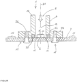
- the sole figure shows a cross-sectional view of a control unit of an electro-pneumatic braking device according to a preferred embodiment of the invention.
- the figure shows a control unit 1 of an electro-pneumatic braking device as a preferred embodiment of an electronic control unit.
- a circuit carrier 2 for example a printed circuit board and a pressure guide 4, as well as a structural unit 6 comprising a pressure sensor element 8 and an associated evaluation unit 10 are shown here from the control unit 1.
- the pressure guide 4 is, for example, tubular and has an inner region 12 pressurized by a pressure medium 5, preferably compressed air.
- the pressure guide 4 is preferably a component of a housing 14 of the control unit 1.
- the housing 14 is, for example, attached directly to a valve block (not shown here) or to a solenoid valve (not shown here) of a solenoid valve device of the electro-pneumatic braking device, with the control unit 1 controlling the solenoid valves of the solenoid valve device.
- the pressure guide 4 is pneumatically connected to an inlet or outlet of at least one solenoid valve or valve (e.g. relay valve) of the solenoid valve device, wherein the pneumatic pressure prevailing at this inlet or outlet is then present in the pressurized, here inner region 12 of the pressure guide 4.
- solenoid valve or valve e.g. relay valve
- the evaluation unit generates an electrical pressure signal that depends on the pressure detected by the pressure sensor element in the pressure guide, which can be analogue or digital.
- the pressure signal is then fed into control electronics 16 on the circuit board 2 of the control unit 1 and processed there.
- the control electronics 16 then (also) controls the solenoid valves of the solenoid valve device depending on the pressure signal from the evaluation unit 10 of the pressure sensor element 8.
- the circuit board 2 contains not only the control electronics 16 with controllers or parts of the control electronics 16 but also the output stages for the solenoid valves.
- the pressure guide 4 contacts the circuit carrier 2 directly. Furthermore, sealing means 20 are arranged in the contact area 18 between the pressure guide 4 and the circuit carrier 2, which seals the inner area 12 of the pressure guide 4, which is pressurized by the pressure medium 5, from the environment, which is formed here by the further interior of the control device 1.
- the pressure sensor element 8 is arranged directly on the circuit carrier 2 and is also arranged thereon in such a way that the pressure sensor element 8 is arranged in the region 12 of the pressure guide 4 that is pressurized with the pressure medium 5.
- the circuit carrier 2 preferably forms a base of the pressure guide 4, on which the pressure sensor element 8 is arranged.
- the evaluation unit 10 is electrically connected directly, i.e. without intermediate elements such as contact feet, to the circuit carrier 2.
- the evaluation unit 10 and the pressure sensor element 8 form a structural unit 6.
- This structural unit 6 is arranged in its own housing, for example.
- a circuit board of the evaluation unit 10 contacts the circuit carrier 2 directly, for example by the evaluation unit 10 or its circuit board having at least one electrical contact surface 11 on the housing of the structural unit 6, which directly contacts the circuit carrier 2.
- the electrical contact surface 11 of the evaluation unit 10 is bonded or soldered to the circuit carrier 2.
- the evaluation unit 10 is formed, for example, by at least one ASIC.
- the evaluation unit 10 and the pressure sensor element 8 can also be arranged separately rather than in one unit. be arranged on different, and in particular mutually facing side surfaces of the circuit carrier 2.
- the sealing means 20 can include an elastic molded seal held in a recess, e.g. groove 22 in a surface of the pressure guide 4 facing the circuit carrier 2, here for example an O-ring which is prestressed against an opposite surface of the circuit carrier 2.
- the O-ring is therefore preferably held in the groove 22 in the end face of the feedthrough 4 facing the circuit carrier, which at the same time forms a flange surface of a flange 24 arranged at the end of the feedthrough 4.
- the flat flange 24 is then preferably detachably attached to the likewise flat circuit carrier 2, for example by means of a screw connection 26, wherein the tensile force of the screws then compresses the O-ring 20 and causes the sealing effect. Therefore, a flat front surface of the pressure guide 4 contacts a flat surface of the circuit carrier 2 directly and/or via the sealing means 20.
- a central or longitudinal axis 21 of the pressure guide 4 is arranged perpendicular to the circuit carrier 2.
- the sealing means can include at least one adhesive bond between a surface of the pressure guide 4 and a surface of the circuit carrier 2.
- the adhesive also serves as a sealing means 20.
- the pressure guide 4 is then permanently connected to the circuit carrier 2 by a material bond.
- the surface of the circuit carrier 2 contacted by the pressure guide 4 is designed, particularly with regard to its geometry (roughness, flatness) and surface structure, so that it (also) has a sealing function.
- a solder resist that is usually present on the circuit carrier 2 can also be used as a sealing surface opposite the end face of the pressure guide 4.
Landscapes
- Engineering & Computer Science (AREA)
- Physics & Mathematics (AREA)
- General Physics & Mathematics (AREA)
- Transportation (AREA)
- Mechanical Engineering (AREA)
- Chemical & Material Sciences (AREA)
- Analytical Chemistry (AREA)
- Microelectronics & Electronic Packaging (AREA)
- Measuring Fluid Pressure (AREA)
- Regulating Braking Force (AREA)
Description
- Die Erfindung betrifft eine elektro-pneumatische Bremseinrichtung für ein Fahrzeug beinhaltend wenigstens ein elektronisches Steuergerät mit wenigstens einem Drucksensorelement gemäß Anspruch 1.
- Aus dem Stand der Technik sind Steuergeräte mit Drucksensoren in Gehäusen mit separatem pneumatischem Anschluss bekannt, die eine Leiterplatte des Steuergeräts elektrisch kontaktieren, z.B. durch Lötung, Schweißung, gebondet, oder gesteckt und mittels eines separaten Druckführungselement mit druckführenden Bauteilen verbunden sind. Die Abdichtung erfolgt dann am Drucksensorgehäuse an dem separaten Druckführungselement. Der Toleranzausgleich erfolgt dann über das separate Druckführungselement, z.B. ein Druckrohr.
-
EP 1 152 231 A2 offenbart ein elektronisches Steuergerät mit einem Gehäuse, einem Deckel und mindestens einer im Deckel angeordneten Leiterplatte, die mit elektronischen Bauelementen bestückt ist, von welchen mindestens eines ein Drucksensor ist, wobei zur Druckzufuhr zum Drucksensor ein am Gehäuse befestigter Schnorchel vorgesehen ist, welcher beim Zusammenfügen von Gehäuse und Deckel mit seinem oberen Teil den Drucksensor umschließt und dessen Rand gegen die Leiterplatte abdichtet. Das Gehäuse verfügt über einen Druckraum mit dem zu messenden Druck, wobei der Druckraum über den Schnorchel mit dem Drucksensor verbunden ist und in welchem ein Ventil angeordnet ist. -
DE 10 2009 026 444 A1 offenbart ein Steuergerät, insbesondere für ein Kraftfahrzeug, mit einem mehrteiligen Gehäuse, in dem zumindest eine Leiterplatte angeordnet ist, wobei zumindest ein Gehäuseteil des Gehäuses einen Luftkanal aufweist, der von einer Öffnung in dem Gehäuseteil zu einem auf der Leiterplatte angeordneten, den Umgebungsdruck ermittelnden Drucksensor führt und gegen die Leiterplatte abgedichtet ist.DE 10 2010 029868 A1 offenbart eine Getriebesteuerung mit einer Trägerplatte sowie einem auf der Trägerplatte aufgenommenen Schaltungsträger, an welchem zumindest Teile einer Getriebesteuerelektronik ausgebildet sind, wobei die Getriebesteuerung ferner einen Drucksensor mit einem Aufnehmer aufweist, insbesondere einen MEMS-Drucksensor, wobei der Drucksensor ohne eigenes Trägergehäuseteil mittels eines in einer Durchgangsöffnung der Trägerplatte fixierten Abstützelements an der Trägerplatte dauerhaft angeordnet ist.DE 10 2010 043393A1 offenbart einen piezoresistiven Drucksensor, wobei der Sensor und eine Auswerteelektronik in einem druckbeaufschlagten Bereich nebeneinander angeordnet sind. Eine gattungsgemäße elektro-pneumatische Bremseinrichtung wird inDE 69309173 T2 offenbart. - Der Erfindung liegt die Aufgabe zugrunde, eine elektro-pneumatische Bremseinrichtung derart weiterzubilden, dass sie in ihren Funktionen zuverlässiger und einfacher herstellbar ist.
- Diese Aufgabe wird erfindungsgemäß durch die Merkmale von Anspruch 1 gelöst.
- Die Erfindung schlägt eine elektro-pneumatische Bremseinrichtung für ein Fahrzeug vor, beinhaltend wenigstens ein elektronisches Steuergerät mit wenigstens einem Drucksensorelement und einem Gehäuse mit einer Druckführung, durch welche das Drucksensorelement mit einem Druckmedium druckbeaufschlagt ist, sowie mit einer Auswerteeinheit, welche ein von dem vom Drucksensorelement erfassten Druck in der Druckführung abhängiges Drucksignal erzeugt, sowie mit einem Schaltungsträger, auf welchem zumindest ein Teil einer Steuerelektronik des Steuergeräts angeordnet ist, wobei das Drucksignal der Auswerteeinheit in die Steuerelektronik eingesteuert wird, wobei
- a) die Druckführung den Schaltungsträger zumindest teilweise direkt kontaktiert und im Kontaktbereich der Druckführung mit dem Schaltungsträger Dichtungsmittel angeordnet sind, welche einen durch das Druckmedium druckbeaufschlagten Bereich der Druckführung gegenüber der Umgebung abdichten, und dass
- b) das Drucksensorelement direkt auf dem Schaltungsträger und auf diesem zudem derart angeordnet ist, dass das Drucksensorelement in dem mit dem Druckmedium druckbeaufschlagten Bereich der Druckführung angeordnet ist, und dass
- c) die Auswerteeinheit mit dem Schaltungsträger elektrisch direkt verbunden ist, wobei die Auswerteeinheit wenigstens eine elektrische Kontaktfläche aufweist, welche den Schaltungsträger direkt kontaktiert, wobei die elektrische Kontaktfläche der Auswerteeinheit auf den Schaltungsträger gebondet oder gelötet ist und wobei
- d) die elektro-pneumatische Bremseinrichtung eine Magnetventileinrichtung beinhaltet, wobei das elektronische Steuergerät abhängig von dem Drucksignal der Auswerteeinheit die Magnetventileinrichtung elektrisch steuert, und wobei
- e) das Gehäuse des Steuergeräts mit einem Ventilblock der Magnetventileinrichtung verbunden ist, und wobei
- f) die Druckführung an wenigstens einen Einlass oder einen Auslass wenigstens eines Ventils der Magnetventileinrichtung angeschlossen ist, wobei
- g) die Dichtungsmittel eine in einer Ausnehmung in einer zum Schaltungsträger weisenden Oberfläche der Druckführung gehaltene, elastische Formdichtung beinhalten, welche gegen eine gegenüberliegende Oberfläche des Schaltungsträger vorgespannt ist, wobei die zum Schaltungsträger weisende Oberfläche der Druckführung eine Stirnfläche der Druckführung ist, und wobei
- h) die zum Schaltungsträger weisende Oberfläche der Druckführung zugleich eine Flanschfläche eines an der Durchführung endseitig angeordneten planen Flansches bildet, wobei der plane Flansch an dem planen Schaltungsträger lösbar befestigt ist.
- Unter einer "direkten Kontaktierung" der Druckführung mit dem Schaltungsträger ist daher zu verstehen, dass lediglich noch die Dichtmittel zwischen der Druckführung und dem Schaltungsträger angeordnet sein können.
- Unter einer "elektrisch direkten Verbindung" zwischen der Auswerteeinheit und dem Schaltungsträger ist zu verstehen, dass diese elektrische Verbindung ohne weitere Verbindungsmittel wie beispielsweise Kontaktfüßchen bewerkstelligt wird.
- Der Schaltungsträger ist bevorzugt als Leiterplatte ausgebildet und beinhaltet neben der Steuerelektronik oder Teilen davon beispielsweise auch Endstufen.
- Mit den oben beschriebenen Maßnahmen kann ein separates Druckführungselement entfallen, wodurch Dichtflächen und auch die Montage des Druckführungselements eingespart werden kann. Weiterhin ergibt sich eine verkleinerte Bauform durch den dann möglichen Entfall des Gehäuses des Drucksensors und des pneumatischen Anschlusses. Weiterhin ist durch die direkte pneumatische Kontaktierung des Drucksensors und der direkten Dichtung der Druckführung auf der Leiterplatte auch kein Toleranzausgleich mehr notwendig.
- Die Erfindung betrifft daher eine elektro-pneumatische Bremseinrichtung als druckmittelbetriebene Einrichtung, beinhaltend wenigstens ein elektronisches Steuergerät. Die elektro-pneumatische Bremseinrichtung beinhaltet dann eine Magnetventileinrichtung, die in einem Ventilblock realisiert ist, wobei die Magnetventileinrichtung wenigstens ein Magnetventil oder Ventil (z.B. Relaisventil) mit wenigstens einem Einlass und wenigstens einem Auslass umfasst. Das elektronische Steuergerät steuert dann abhängig von dem Drucksignal der Auswerteeinrichtung die Magnetventileinrichtung der elektro-pneumatischen Bremseinrichtung elektrisch. Das Drucksignal kann beispielsweise einen von der Magnetventileinrichtung ausgesteuerten Ist-Bremsdruck repräsentieren, welcher dann im Rahmen einer in dem Steuergerät implementierten Bremsdruckregelung beispielsweise auf einen Soll-Bremsdruck geregelt wird. Die Magnetventileinrichtung und das Steuergerät sind dann beispielsweise in einem elektro-pneumatischen Druckregelmodul integriert.
- Das Gehäuse des Steuergeräts ist dann mit dem Ventilblock der Magnetventileinrichtung verbunden und die Druckführung an wenigstens einen Einlass oder einen Auslass wenigstens eines Ventils (z.B. Relaisventil) oder Magnetventils der Magnetventileinrichtung angeschlossen.
- Durch die in den Unteransprüchen aufgeführten Maßnahmen sind vorteilhafte Weiterbildungen und Verbesserungen der in Anspruch 1 angegebenen Erfindung möglich.
- Besonders bevorzugt kontaktiert eine Platine der Auswerteeinheit den Schaltungsträger direkt.
- Gemäß einer Weiterbildung kann die Auswerteeinheit durch wenigstens einen ASIC gebildet werden. Bei einem ASIC handelt es sich um eine anwendungsspezifische integrierte Schaltung (Application-Specific Integrated Circuit) als elektronische Schaltung, die als integrierter Schaltkreis realisiert ist. Die Funktion eines ASICs ist damit nicht mehr veränderbar. Vorzugsweise kommt ein rein digitaler ASIC zum Einsatz, der eine große Zahl von Logikfunktionen integriert, die sonst aus diversen Standardbausteinen wie Prozessor, Logikfamilien oder ähnlichen Bausteinen zusammengestellt werden müssten. Alternativ kann ein Mixed-Signal-ASIC zum Einsatz kommen, der aus digitalen und analogen Funktionen besteht. Dabei ist dann eine analoge Schaltung wie z. B. ein Analog-Digital-Wandler vorhanden.
- Gemäß einer Variante können die Auswerteeinheit und das wenigstens eine Drucksensorelement auf verschiedenen Seitenflächen des Schaltungsträgers angeordnet sein.
- Gemäß einer weiteren Variante können die Auswerteeinheit und das wenigstens eine Drucksensorelement auch eine Baueinheit bilden. Diese Baueinheit kann dann auf einem separaten Träger, z.B. einer Keramikplatte oder einem FR4, oder in einem eigenen Gehäuse angeordnet sein.
- Zusätzlich können die Dichtungsmittel wenigstens eine Klebung zwischen einer Oberfläche der Druckführung und einer Oberfläche des Schaltungsträgers beinhalten. In diesem Fall dient der Klebstoff neben seiner Funktion als den Stoffschluss zwischen Druckführung und Schaltungsträger erzeugendes Mittel zugleich als Dichtungsmittel.
- Die Druckführung kann insbesondere rohrförmig sein. Dabei kann insbesondere eine Stirnfläche einer rohrförmigen Druckführung eine Fläche des Schaltungsträgers direkt kontaktieren. In diesem Fall bildet dann der Schaltungsträger einen Boden der Druckführung aus. Insbesondere ist eine Mittel- oder Längsachse der Druckführung senkrecht zu dem Schaltungsträger angeordnet.
- Insbesondere ist auch die von der Druckführung kontaktierte Oberfläche des Schaltungsträgers insbesondere hinsichtlich ihrer Geometrie (Planheit) und Oberflächenstruktur ausgebildet, dass sie eine dichtende Funktion hat. Zur Schaffung einer geeigneten Oberflächenstruktur auf dem Schaltungsträger, der beispielsweise als Leiterplatte ausgebildet ist, können beispielsweise die Leiterbahnen entflechtet und die Durchkontaktierung abgedichtet werden. Auch kann ein in der Regel auf dem Schaltungsträger ohnehin vorhandener Lötstopplack eine Dichtfläche gegenüber der Druckführung bilden.
- Empfindliche Bereiche wie die elektrische Kontaktierung des Drucksensorelements und/oder der Auswerteeinheit auf dem Schaltungsträger können durch Gel, Lack, etc. geschützt werden.
- Auch können mehrere Drucksensorelemente und Auswerteeinheiten in einem Array (Feld) auf dem Schaltungsträger vorgesehen werden, wobei die pneumatische Kontaktierung zu der Druckführung dann beispielsweise über mehrere Druckkanäle unter Verwendung von einem oder mehreren Dichtelementen (O-Ring, Formdichtung, Klebung, eingespritzte Dichtung) erfolgen kann.
- Der Schaltungsträger und dessen direkte pneumatische Kontaktierung mit der Druckführung können direkt auf oder in einem Magnetventil oder auf oder in einem Ventilblock angeordnet sein.
- Alternativ kann auch wenigstens ein zusätzliches druckführendes Bauteil oder ein Kanal vorgesehen werden, welches das Magnetventil oder den Ventilblock mit der Druckführung pneumatisch verbindet.
- Eine Kalibrierung der Auswerteeinheit des wenigstens einen Drucksensorelements kann dann nach der Montage auf dem Schaltungsträger erfolgen, um Einflüsse durch mechanische Verspannungen auf das Drucksignal der Auswerteeinheit zu reduzieren.
- Weiterhin kann auch der Schaltungsträger, beispielsweise eine Leiterplatte an dem Gehäuse befestigt sein.
- Weitere die Erfindung verbessernde Maßnahmen werden nachstehend gemeinsam mit der Beschreibung eines Ausführungsbeispiels der Erfindung anhand der Zeichnung näher dargestellt.
- In der ein Ausführungsbeispiel der Erfindung darstellenden Zeichnung zeigt die einzige Figur eine Querschnittsdarstellung eines Steuergeräts einer elektro-pneumatischen Bremseinrichtung gemäß einer bevorzugten Ausführungsform der Erfindung.
- In der Figur ist als bevorzugte Ausführungsform eines elektronischen Steuergeräts ein Steuergerät 1 einer elektro-pneumatischen Bremseinrichtung gezeigt. Aus Maßstabsgründen sind von dem Steuergerät 1 hier lediglich ein Schaltungsträger 2, beispielsweise eine Leiterplatte und eine Druckführung 4 sowie eine Baueinheit 6 aus einem Drucksensorelement 8 und einer zugeordneten Auswerteeinheit 10 gezeigt.
- Die Druckführung 4 ist hier beispielsweise rohrförmig ausgebildet und weist einen hier inneren, durch ein Druckmedium 5, hier bevorzugt mit Druckluft druckbeaufschlagten Bereich 12 auf. Die Druckführung 4 ist bevorzugt ein Bestandteil eines Gehäuses 14 des Steuergeräts 1. Das Gehäuse 14 ist beispielsweise direkt an einem hier nicht gezeigten Ventilblock oder an einem hier nicht gezeigten Magnetventil einer Magnetventileinrichtung der elektro-pneumatischen Bremseinrichtung befestigt, wobei das Steuergerät 1 die Magnetventile der Magnetventileinrichtung steuert.
- Beispielsweise ist die Druckführung 4 mit einem Einlass oder Auslass wenigstens eines Magnetventils oder Ventils (z.B. Relaisventil) der Magnetventileinrichtung pneumatisch verbunden, wobei dann in dem druckbeaufschlagten, hier inneren Bereich 12 der Druckführung 4 dann der pneumatische Druck ansteht, der an diesem Einlass oder Auslass herrscht.
- Die Auswerteeinheit erzeugt ein von dem vom Drucksensorelement erfassten Druck in der Druckführung abhängiges elektrisches Drucksignal, welches analog oder bereits digital sein kann. Das Drucksignal wird dann in eine Steuerelektronik 16 auf dem Schaltungsträger 2 des Steuergeräts 1 eingesteuert und dort verarbeitet. Die Steuerelektronik 16 steuert dann (auch) abhängig von dem Drucksignal der Auswerteeinheit 10 des Drucksensorelements 8 die Magnetventile der Magnetventileinrichtung an. Der Schaltungsträger 2 beinhaltet neben der Steuerelektronik 16 mit Controllern oder Teilen der Steuerelektronik 16 auch die Endstufen für die Magnetventile.
- Wie aus der Figur hervorgeht, kontaktiert die Druckführung 4 den Schaltungsträger 2 direkt. Weiterhin sind im Kontaktbereich 18 zwischen der Druckführung 4 und dem Schaltungsträger 2 Dichtungsmittel 20 angeordnet, welche den durch das Druckmedium 5 druckbeaufschlagten, hier inneren Bereich 12 der Druckführung 4 gegenüber der Umgebung abdichten, welche hier durch das weitere Innere des Steuergeräts 1 gebildet wird.
- Weiterhin ist das Drucksensorelement 8 direkt auf dem Schaltungsträger 2 und auf diesem zudem derart angeordnet ist, dass das Drucksensorelement 8 in dem mit dem Druckmedium 5 druckbeaufschlagten Bereich 12 der Druckführung 4 angeordnet ist. Hier bildet der Schaltungsträger 2 bevorzugt einen Boden der Druckführung 4 aus, an dem das Drucksensorelement 8 angeordnet ist. Weiterhin ist die Auswerteeinheit 10 direkt, d.h. ohne Zwischenelemente wie etwa Kontaktfüßchen mit dem Schaltungsträger 2 elektrisch verbunden.
- Gemäß der hier beschriebenen bevorzugten Ausführungsform bilden die Auswerteeinheit 10 und das Drucksensorelement 8 eine Baueinheit 6. Diese Baueinheit 6 ist hier beispielsweise in einem eigenen Gehäuse angeordnet. Dabei kontaktiert eine Platine der Auswerteeinheit 10 den Schaltungsträger 2 direkt, beispielsweise dadurch, dass die Auswerteeinheit 10 bzw. deren Platine wenigstens eine elektrische Kontaktfläche 11 am Gehäuse der Baueinheit 6 aufweist, welche den Schaltungsträger 2 direkt kontaktiert. Dabei ist die elektrische Kontaktfläche 11 der Auswerteeinheit 10 auf den Schaltungsträger 2 gebondet oder gelötet. Die Auswerteeinheit 10 wird beispielsweise durch wenigstens einen ASIC gebildet.
- Gemäß einer alternativen, hier nicht gezeigten Ausführungsform können die Auswerteeinheit 10 und das Drucksensorelement 8 auch nicht in einer Baueinheit sondern separat auf verschiedenen, und insbesondere voneinander weg weisenden Seitenflächen des Schaltungsträgers 2 angeordnet sein.
- Bevorzugt, wie hier gezeigt, können die Dichtungsmittel 20 eine in einer Ausnehmung, z.B. Nut 22 in einer zum Schaltungsträger 2 weisenden Oberfläche der Druckführung 4 gehaltene, elastische Formdichtung beinhalten, hier beispielsweise einen O-Ring, welcher gegen eine gegenüber liegende Oberfläche des Schaltungsträgers 2 vorgespannt ist. Der O-Ring ist hier daher bevorzugt in der Nut 22 in der zum Schaltungsträger weisenden Stirnfläche der Durchführung 4 gehalten, welche zugleich eine Flanschfläche eines an der Durchführung 4 endseitig angeordneten Flansches 24 bildet. Der plane Flansch 24 ist dann hier bevorzugt lösbar an dem ebenfalls planen Schaltungsträger 2 befestigt, beispielsweise mittels einer Schraubverbindung 26, wobei die Zugkraft der Schrauben dann den O-Ring 20 komprimiert und die Dichtwirkung hervorruft. Daher kontaktiert hier eine plane Stirnfläche der Druckführung 4 eine plane Oberfläche des Schaltungsträgers 2 direkt und/oder über die Dichtungsmittel 20. Insbesondere ist eine Mittel- oder Längsachse 21 der Druckführung 4 senkrecht zu dem Schaltungsträger 2 angeordnet.
- Alternativ oder zusätzlich können die Dichtungsmittel wenigstens eine Klebung zwischen einer Oberfläche der Druckführung 4 und einer Oberfläche des Schaltungsträgers 2 beinhalten. In diesem Fall dient der Klebstoff zugleich als Dichtungsmittel 20. Die Druckführung 4 ist dann mit dem Schaltungsträger 2 durch Stoffschluss unlösbar verbunden.
- Insbesondere ist die von der Druckführung 4 kontaktierte Oberfläche des Schaltungsträgers 2 insbesondere hinsichtlich ihrer Geometrie (Rauheit, Planheit) und Oberflächenstruktur ausgebildet, dass sie (auch) eine dichtende Funktion hat. Auch kann ein in der Regel auf dem Schaltungsträger 2 vorhandener Lötstopplack als Dichtfläche gegenüber der Stirnfläche der Druckführung 4 verwendet werden.
-
- 1
- Steuergerät
- 2
- Schaltungsträger
- 4
- Druckführung
- 5
- Druckmedium
- 6
- Baueinheit
- 8
- Drucksensorelement
- 10
- Auswerteeinheit
- 11
- Kontaktfläche
- 12
- druckbeaufschlagter Bereich
- 14
- Gehäuse
- 16
- Steuerelektronik
- 18
- Kontaktbereich
- 20
- Dichtungsmittel
- 21
- Mittelachse
- 22
- Nut
- 24
- Flansch
- 25
- Dichtungsmittel
- 26
- Schraubverbindung
Claims (8)
- Elektro-pneumatische Bremseinrichtung für ein Fahrzeug, beinhaltend wenigstens ein elektronisches Steuergerät (1) mit wenigstens einem Drucksensorelement (8) und einem Gehäuse (14) mit einer Druckführung (4), durch welche das Drucksensorelement (8) mit einem Druckmedium (5) druckbeaufschlagt ist, sowie mit einer Auswerteeinheit (10), welche ein von dem vom Drucksensorelement (8) erfassten Druck in der Druckführung (4) abhängiges Drucksignal erzeugt, sowie mit einem planen Schaltungsträger (2), auf welchem zumindest ein Teil einer Steuerelektronik (16) des Steuergeräts (1) angeordnet ist, wobei das Drucksignal der Auswerteeinheit (10) in die Steuerelektronik (16) eingesteuert wird, wobeia) die Druckführung (4) den Schaltungsträger (2) zumindest teilweise direkt kontaktiert und im Kontaktbereich (18) der Druckführung (4) mit dem Schaltungsträger (2) Dichtungsmittel (20) angeordnet sind, welche einen durch das Druckmedium (5) druckbeaufschlagten Bereich (12) der Druckführung (4) gegenüber der Umgebung abdichten, und dassb) das Drucksensorelement (8) direkt auf dem Schaltungsträger (2) und auf diesem zudem derart angeordnet ist, dass das Drucksensorelement (8) in dem mit dem Druckmedium (5) druckbeaufschlagten Bereich (12) der Druckführung (4) angeordnet ist, und dassc) die Auswerteeinheit (10) mit dem Schaltungsträger (2) elektrisch direkt verbunden ist, wobei die Auswerteeinheit (10) wenigstens eine elektrische Kontaktfläche (11) aufweist, welche den Schaltungsträger (2) direkt kontaktiert, wobei die elektrische Kontaktfläche (11) der Auswerteeinheit (10) auf den Schaltungsträger (2) gebondet oder gelötet ist und wobeid) die elektro-pneumatische Bremseinrichtung eine Magnetventileinrichtung beinhaltet, wobei das elektronische Steuergerät (1) abhängig von dem Drucksignal der Auswerteeinheit (10) die Magnetventileinrichtung elektrisch steuert, und wobeie) das Gehäuse (14) des Steuergeräts (1) mit einem Ventilblock der Magnetventileinrichtung verbunden ist, und wobeif) die Druckführung (4) an wenigstens einen Einlass oder einen Auslass wenigstens eines Ventils der Magnetventileinrichtung angeschlossen ist, wobeig) die Dichtungsmittel (20) eine in einer Ausnehmung (22) in einer zum Schaltungsträger (2) weisenden Oberfläche der Druckführung (4) gehaltene, elastische Formdichtung (20) beinhalten, welche gegen eine gegenüberliegende Oberfläche des Schaltungsträgers (2) vorgespannt ist, wobei die zum Schaltungsträger (2) weisende Oberfläche der Druckführung (4) eine Stirnfläche der Druckführung (4) ist, dadurch gekennzeichnet, dassh) die zum Schaltungsträger (2) weisende Oberfläche der Druckführung (4) zugleich eine Flanschfläche eines an der Druckführung (4) endseitig angeordneten planen Flansches (24) bildet, wobei der plane Flansch (24) an dem planen Schaltungsträger (2) lösbar befestigt ist.
- Elektro-pneumatische Bremseinrichtung nach Anspruch 1, dadurch gekennzeichnet, dass eine Platine der Auswerteeinheit (10) den Schaltungsträger (2) direkt kontaktiert.
- Elektro-pneumatische Bremseinrichtung nach einem der vorhergehenden Ansprüche, dadurch gekennzeichnet, dass die Auswerteeinheit (10) durch wenigstens einen ASIC gebildet wird.
- Elektro-pneumatische Bremseinrichtung nach einem der vorhergehenden Ansprüche, dadurch gekennzeichnet, dass die Auswerteeinheit (10) und das wenigstens eine Drucksensorelement (8) auf verschiedenen, voneinander wegweisenden Seitenflächen des Schaltungsträgers (2) angeordnet sind.
- Elektro-pneumatische Bremseinrichtung nach einem der vorhergehenden Ansprüche, dadurch gekennzeichnet, dass die Auswerteeinheit (10) und das wenigstens eine Drucksensorelement (8) eine Baueinheit (6) bilden.
- Elektro-pneumatische Bremseinrichtung nach Anspruch 5, dadurch gekennzeichnet, dass die Baueinheit (6) auf einem separaten Träger oder in einem eigenen Gehäuse angeordnet ist.
- Elektro-pneumatische Bremseinrichtung nach einem der vorhergehenden Ansprüche, dadurch gekennzeichnet, dass die Kontaktflächen (11) durch ein Dichtungsmittel (25) z.B. Gel, Lackierung, Festdichtung vor Verschmutzung geschützt wird.
- Elektro-pneumatische Bremseinrichtung nach einem der vorhergehenden Ansprüche, dadurch gekennzeichnet, dass die Dichtungsmittel (20) wenigstens eine Klebung zwischen einer Oberfläche der Druckführung (4) und einer Oberfläche des Schaltungsträgers (2) beinhalten.
Applications Claiming Priority (2)
| Application Number | Priority Date | Filing Date | Title |
|---|---|---|---|
| DE102017106553.9A DE102017106553A1 (de) | 2017-03-27 | 2017-03-27 | Steuergerät für ein Fahrzeug mit wenigstens einem Drucksensorelement |
| PCT/EP2018/057129 WO2018177833A1 (de) | 2017-03-27 | 2018-03-21 | Steuergerät für ein fahrzeug mit wenigstens einem drucksensorelement |
Publications (2)
| Publication Number | Publication Date |
|---|---|
| EP3603358A1 EP3603358A1 (de) | 2020-02-05 |
| EP3603358B1 true EP3603358B1 (de) | 2024-10-23 |
Family
ID=61832487
Family Applications (1)
| Application Number | Title | Priority Date | Filing Date |
|---|---|---|---|
| EP18714468.8A Active EP3603358B1 (de) | 2017-03-27 | 2018-03-21 | Steuergerät für ein fahrzeug mit wenigstens einem drucksensorelement |
Country Status (5)
| Country | Link |
|---|---|
| US (1) | US11156524B2 (de) |
| EP (1) | EP3603358B1 (de) |
| CN (1) | CN110476491B (de) |
| DE (1) | DE102017106553A1 (de) |
| WO (1) | WO2018177833A1 (de) |
Citations (1)
| Publication number | Priority date | Publication date | Assignee | Title |
|---|---|---|---|---|
| DE69309173T2 (de) * | 1992-07-22 | 1997-07-03 | Grau Ltd | Bremssysteme |
Family Cites Families (9)
| Publication number | Priority date | Publication date | Assignee | Title |
|---|---|---|---|---|
| DE10022124B4 (de) | 2000-05-06 | 2010-01-14 | Wabco Gmbh | Elektronisches Steuergerät |
| DE102004053200A1 (de) | 2004-11-04 | 2006-05-11 | Wabco Gmbh & Co.Ohg | Mechatronik |
| DE102006044764A1 (de) * | 2006-09-20 | 2008-04-03 | Wabco Gmbh | Ventilsteuereinheit, insbesondere Vorsteuereinheit für einen Druckmodulator eines Nutzfahrzeuges |
| DE102009026444A1 (de) | 2009-05-25 | 2010-12-02 | Robert Bosch Gmbh | Steuergerät mit Drucksensor |
| US20110079085A1 (en) | 2009-10-06 | 2011-04-07 | Robert John Kanda | Integrated fluid pressure sensor system |
| US8245575B2 (en) * | 2009-12-08 | 2012-08-21 | Jen-Huang Albert Chiou | Pressure sensor device with breakwater to reduce protective gel vibration |
| DE102010029868A1 (de) * | 2010-06-09 | 2011-12-15 | Zf Friedrichshafen Ag | Getriebesteuerung |
| WO2012177737A1 (en) * | 2011-06-21 | 2012-12-27 | Ohio University | Device and method for monitoring interaction between a fluid and a wall |
| DE102013205155B4 (de) * | 2013-03-22 | 2023-05-04 | Robert Bosch Gmbh | Vorrichtung zur Befestigung eines Drucksensors an einer mit einem Druckkanal versehenen Trägerplatte |
-
2017
- 2017-03-27 DE DE102017106553.9A patent/DE102017106553A1/de active Pending
-
2018
- 2018-03-21 WO PCT/EP2018/057129 patent/WO2018177833A1/de not_active Ceased
- 2018-03-21 US US16/497,272 patent/US11156524B2/en active Active
- 2018-03-21 EP EP18714468.8A patent/EP3603358B1/de active Active
- 2018-03-21 CN CN201880021981.4A patent/CN110476491B/zh active Active
Patent Citations (1)
| Publication number | Priority date | Publication date | Assignee | Title |
|---|---|---|---|---|
| DE69309173T2 (de) * | 1992-07-22 | 1997-07-03 | Grau Ltd | Bremssysteme |
Also Published As
| Publication number | Publication date |
|---|---|
| US20200378855A1 (en) | 2020-12-03 |
| CN110476491A (zh) | 2019-11-19 |
| CN110476491B (zh) | 2022-03-01 |
| EP3603358A1 (de) | 2020-02-05 |
| US11156524B2 (en) | 2021-10-26 |
| WO2018177833A1 (de) | 2018-10-04 |
| DE102017106553A1 (de) | 2018-09-27 |
Similar Documents
| Publication | Publication Date | Title |
|---|---|---|
| EP0594808B1 (de) | Vorrichtung zum messen von druck und differenzdruck mit dreiteiligem gewindegehäuse und einem winkelring | |
| EP1518099B1 (de) | Hochdruck-sensor-gehaeuse mit verbindungsteil (emv-abschirmung) | |
| WO1998034089A1 (de) | Drucksensor-bauteil mit schlauchanschluss | |
| DE102010040373B4 (de) | Mikromechanisches Drucksensorelement | |
| EP1152231B1 (de) | Drucksensorvorrichtung | |
| EP3516259B1 (de) | Pneumatische scheibenbremse | |
| DE10135568A1 (de) | Drucksensor | |
| EP3050745A1 (de) | Pneumatische steuer- und messvorrichtung sowie sitzkomfortsystem | |
| DE102015206470A1 (de) | Vorrichtung zum Bestimmen eines Drucks und Verfahren zum Herstellen derselben | |
| EP2435810A1 (de) | Steuergerät mit drucksensor | |
| EP0291516B1 (de) | Elektrohydraulische vorrichtung zur kontinuierlichen überwachung des druckes in einer hydraulischen kraftfahrzeug-bremsanlage | |
| DE102008033592B4 (de) | Mikromechanischer Drucksensor | |
| EP1339586B1 (de) | Sensoranordnung für einen unterdruck-bremskraftverstärker und damit ausgerüsteter unterdruck-bremskraftverstärker | |
| WO2018177833A1 (de) | Steuergerät für ein fahrzeug mit wenigstens einem drucksensorelement | |
| DE10315405A1 (de) | Vorrichtung zur Druckmessung | |
| DE3128408C2 (de) | ||
| WO2002046011A1 (de) | Sensoranordnung für einen unterdruck-bremskraftverstärker | |
| DE102016124026A1 (de) | Drucksensor zur Ermittlung eines Differenzdruckes | |
| DE102005048450B4 (de) | Sensor mit einem auswechselbaren Sensorelement, insbesondere Drucksensor | |
| DE102021111671A1 (de) | Druckmesszelle mit Auswerteelektronik auf Verdrängungskörper | |
| EP0868658A1 (de) | Kraftmessvorrichtung | |
| DE102006050801B4 (de) | Mechatronische Baugruppe | |
| EP0203283B1 (de) | Drucksensor mit Bourdonrohr | |
| DE4314844A1 (de) | Druckmeßvorrichtung mit einer Widerstandsmeßbrücke | |
| DE102016124025A1 (de) | Drucksensor zur Ermittlung eines Differenzdruckes |
Legal Events
| Date | Code | Title | Description |
|---|---|---|---|
| STAA | Information on the status of an ep patent application or granted ep patent |
Free format text: STATUS: UNKNOWN |
|
| STAA | Information on the status of an ep patent application or granted ep patent |
Free format text: STATUS: THE INTERNATIONAL PUBLICATION HAS BEEN MADE |
|
| PUAI | Public reference made under article 153(3) epc to a published international application that has entered the european phase |
Free format text: ORIGINAL CODE: 0009012 |
|
| STAA | Information on the status of an ep patent application or granted ep patent |
Free format text: STATUS: REQUEST FOR EXAMINATION WAS MADE |
|
| 17P | Request for examination filed |
Effective date: 20191028 |
|
| AK | Designated contracting states |
Kind code of ref document: A1 Designated state(s): AL AT BE BG CH CY CZ DE DK EE ES FI FR GB GR HR HU IE IS IT LI LT LU LV MC MK MT NL NO PL PT RO RS SE SI SK SM TR |
|
| AX | Request for extension of the european patent |
Extension state: BA ME |
|
| RIN1 | Information on inventor provided before grant (corrected) |
Inventor name: POHLEY, KARIN Inventor name: NIEDERMEIER, STEFAN Inventor name: MLYNARSKI, AMADEUS Inventor name: HUBER, CHRISTIAN Inventor name: LECHNER, KLAUS Inventor name: ROETHER, FRIEDBERT |
|
| DAV | Request for validation of the european patent (deleted) | ||
| DAX | Request for extension of the european patent (deleted) | ||
| STAA | Information on the status of an ep patent application or granted ep patent |
Free format text: STATUS: EXAMINATION IS IN PROGRESS |
|
| 17Q | First examination report despatched |
Effective date: 20220104 |
|
| GRAP | Despatch of communication of intention to grant a patent |
Free format text: ORIGINAL CODE: EPIDOSNIGR1 |
|
| STAA | Information on the status of an ep patent application or granted ep patent |
Free format text: STATUS: GRANT OF PATENT IS INTENDED |
|
| INTG | Intention to grant announced |
Effective date: 20240620 |
|
| GRAS | Grant fee paid |
Free format text: ORIGINAL CODE: EPIDOSNIGR3 |
|
| GRAA | (expected) grant |
Free format text: ORIGINAL CODE: 0009210 |
|
| STAA | Information on the status of an ep patent application or granted ep patent |
Free format text: STATUS: THE PATENT HAS BEEN GRANTED |
|
| AK | Designated contracting states |
Kind code of ref document: B1 Designated state(s): AL AT BE BG CH CY CZ DE DK EE ES FI FR GB GR HR HU IE IS IT LI LT LU LV MC MK MT NL NO PL PT RO RS SE SI SK SM TR |
|
| REG | Reference to a national code |
Ref country code: GB Ref legal event code: FG4D Free format text: NOT ENGLISH |
|
| REG | Reference to a national code |
Ref country code: CH Ref legal event code: EP |
|
| REG | Reference to a national code |
Ref country code: DE Ref legal event code: R096 Ref document number: 502018015250 Country of ref document: DE |
|
| REG | Reference to a national code |
Ref country code: IE Ref legal event code: FG4D Free format text: LANGUAGE OF EP DOCUMENT: GERMAN |
|
| P01 | Opt-out of the competence of the unified patent court (upc) registered |
Free format text: CASE NUMBER: APP_57689/2024 Effective date: 20241022 |
|
| REG | Reference to a national code |
Ref country code: SE Ref legal event code: TRGR |
|
| REG | Reference to a national code |
Ref country code: LT Ref legal event code: MG9D |
|
| REG | Reference to a national code |
Ref country code: NL Ref legal event code: MP Effective date: 20241023 |
|
| PG25 | Lapsed in a contracting state [announced via postgrant information from national office to epo] |
Ref country code: NL Free format text: LAPSE BECAUSE OF FAILURE TO SUBMIT A TRANSLATION OF THE DESCRIPTION OR TO PAY THE FEE WITHIN THE PRESCRIBED TIME-LIMIT Effective date: 20241023 |
|
| PG25 | Lapsed in a contracting state [announced via postgrant information from national office to epo] |
Ref country code: NL Free format text: LAPSE BECAUSE OF FAILURE TO SUBMIT A TRANSLATION OF THE DESCRIPTION OR TO PAY THE FEE WITHIN THE PRESCRIBED TIME-LIMIT Effective date: 20241023 |
|
| PG25 | Lapsed in a contracting state [announced via postgrant information from national office to epo] |
Ref country code: PT Free format text: LAPSE BECAUSE OF FAILURE TO SUBMIT A TRANSLATION OF THE DESCRIPTION OR TO PAY THE FEE WITHIN THE PRESCRIBED TIME-LIMIT Effective date: 20250224 Ref country code: HR Free format text: LAPSE BECAUSE OF FAILURE TO SUBMIT A TRANSLATION OF THE DESCRIPTION OR TO PAY THE FEE WITHIN THE PRESCRIBED TIME-LIMIT Effective date: 20241023 Ref country code: IS Free format text: LAPSE BECAUSE OF FAILURE TO SUBMIT A TRANSLATION OF THE DESCRIPTION OR TO PAY THE FEE WITHIN THE PRESCRIBED TIME-LIMIT Effective date: 20250223 |
|
| PG25 | Lapsed in a contracting state [announced via postgrant information from national office to epo] |
Ref country code: FI Free format text: LAPSE BECAUSE OF FAILURE TO SUBMIT A TRANSLATION OF THE DESCRIPTION OR TO PAY THE FEE WITHIN THE PRESCRIBED TIME-LIMIT Effective date: 20241023 |
|
| PG25 | Lapsed in a contracting state [announced via postgrant information from national office to epo] |
Ref country code: BG Free format text: LAPSE BECAUSE OF FAILURE TO SUBMIT A TRANSLATION OF THE DESCRIPTION OR TO PAY THE FEE WITHIN THE PRESCRIBED TIME-LIMIT Effective date: 20241023 |
|
| PG25 | Lapsed in a contracting state [announced via postgrant information from national office to epo] |
Ref country code: ES Free format text: LAPSE BECAUSE OF FAILURE TO SUBMIT A TRANSLATION OF THE DESCRIPTION OR TO PAY THE FEE WITHIN THE PRESCRIBED TIME-LIMIT Effective date: 20241023 |
|
| PG25 | Lapsed in a contracting state [announced via postgrant information from national office to epo] |
Ref country code: NO Free format text: LAPSE BECAUSE OF FAILURE TO SUBMIT A TRANSLATION OF THE DESCRIPTION OR TO PAY THE FEE WITHIN THE PRESCRIBED TIME-LIMIT Effective date: 20250123 |
|
| PG25 | Lapsed in a contracting state [announced via postgrant information from national office to epo] |
Ref country code: LV Free format text: LAPSE BECAUSE OF FAILURE TO SUBMIT A TRANSLATION OF THE DESCRIPTION OR TO PAY THE FEE WITHIN THE PRESCRIBED TIME-LIMIT Effective date: 20241023 Ref country code: GR Free format text: LAPSE BECAUSE OF FAILURE TO SUBMIT A TRANSLATION OF THE DESCRIPTION OR TO PAY THE FEE WITHIN THE PRESCRIBED TIME-LIMIT Effective date: 20250124 |
|
| PG25 | Lapsed in a contracting state [announced via postgrant information from national office to epo] |
Ref country code: PL Free format text: LAPSE BECAUSE OF FAILURE TO SUBMIT A TRANSLATION OF THE DESCRIPTION OR TO PAY THE FEE WITHIN THE PRESCRIBED TIME-LIMIT Effective date: 20241023 |
|
| PG25 | Lapsed in a contracting state [announced via postgrant information from national office to epo] |
Ref country code: RS Free format text: LAPSE BECAUSE OF FAILURE TO SUBMIT A TRANSLATION OF THE DESCRIPTION OR TO PAY THE FEE WITHIN THE PRESCRIBED TIME-LIMIT Effective date: 20250123 |
|
| PG25 | Lapsed in a contracting state [announced via postgrant information from national office to epo] |
Ref country code: SM Free format text: LAPSE BECAUSE OF FAILURE TO SUBMIT A TRANSLATION OF THE DESCRIPTION OR TO PAY THE FEE WITHIN THE PRESCRIBED TIME-LIMIT Effective date: 20241023 |
|
| PG25 | Lapsed in a contracting state [announced via postgrant information from national office to epo] |
Ref country code: DK Free format text: LAPSE BECAUSE OF FAILURE TO SUBMIT A TRANSLATION OF THE DESCRIPTION OR TO PAY THE FEE WITHIN THE PRESCRIBED TIME-LIMIT Effective date: 20241023 |
|
| PG25 | Lapsed in a contracting state [announced via postgrant information from national office to epo] |
Ref country code: EE Free format text: LAPSE BECAUSE OF FAILURE TO SUBMIT A TRANSLATION OF THE DESCRIPTION OR TO PAY THE FEE WITHIN THE PRESCRIBED TIME-LIMIT Effective date: 20241023 |
|
| PG25 | Lapsed in a contracting state [announced via postgrant information from national office to epo] |
Ref country code: RO Free format text: LAPSE BECAUSE OF FAILURE TO SUBMIT A TRANSLATION OF THE DESCRIPTION OR TO PAY THE FEE WITHIN THE PRESCRIBED TIME-LIMIT Effective date: 20241023 |
|
| REG | Reference to a national code |
Ref country code: DE Ref legal event code: R097 Ref document number: 502018015250 Country of ref document: DE |
|
| PG25 | Lapsed in a contracting state [announced via postgrant information from national office to epo] |
Ref country code: SK Free format text: LAPSE BECAUSE OF FAILURE TO SUBMIT A TRANSLATION OF THE DESCRIPTION OR TO PAY THE FEE WITHIN THE PRESCRIBED TIME-LIMIT Effective date: 20241023 |
|
| PG25 | Lapsed in a contracting state [announced via postgrant information from national office to epo] |
Ref country code: CZ Free format text: LAPSE BECAUSE OF FAILURE TO SUBMIT A TRANSLATION OF THE DESCRIPTION OR TO PAY THE FEE WITHIN THE PRESCRIBED TIME-LIMIT Effective date: 20241023 |
|
| PG25 | Lapsed in a contracting state [announced via postgrant information from national office to epo] |
Ref country code: IT Free format text: LAPSE BECAUSE OF FAILURE TO SUBMIT A TRANSLATION OF THE DESCRIPTION OR TO PAY THE FEE WITHIN THE PRESCRIBED TIME-LIMIT Effective date: 20241023 |
|
| PLBE | No opposition filed within time limit |
Free format text: ORIGINAL CODE: 0009261 |
|
| STAA | Information on the status of an ep patent application or granted ep patent |
Free format text: STATUS: NO OPPOSITION FILED WITHIN TIME LIMIT |
|
| 26N | No opposition filed |
Effective date: 20250724 |
|
| PG25 | Lapsed in a contracting state [announced via postgrant information from national office to epo] |
Ref country code: MC Free format text: LAPSE BECAUSE OF FAILURE TO SUBMIT A TRANSLATION OF THE DESCRIPTION OR TO PAY THE FEE WITHIN THE PRESCRIBED TIME-LIMIT Effective date: 20241023 |
|
| REG | Reference to a national code |
Ref country code: CH Ref legal event code: H13 Free format text: ST27 STATUS EVENT CODE: U-0-0-H10-H13 (AS PROVIDED BY THE NATIONAL OFFICE) Effective date: 20251023 |
|
| PG25 | Lapsed in a contracting state [announced via postgrant information from national office to epo] |
Ref country code: LU Free format text: LAPSE BECAUSE OF NON-PAYMENT OF DUE FEES Effective date: 20250321 |
|
| REG | Reference to a national code |
Ref country code: BE Ref legal event code: MM Effective date: 20250331 |
|
| PG25 | Lapsed in a contracting state [announced via postgrant information from national office to epo] |
Ref country code: BE Free format text: LAPSE BECAUSE OF NON-PAYMENT OF DUE FEES Effective date: 20250331 |
|
| PG25 | Lapsed in a contracting state [announced via postgrant information from national office to epo] |
Ref country code: CH Free format text: LAPSE BECAUSE OF NON-PAYMENT OF DUE FEES Effective date: 20250331 |
|
| PG25 | Lapsed in a contracting state [announced via postgrant information from national office to epo] |
Ref country code: IE Free format text: LAPSE BECAUSE OF NON-PAYMENT OF DUE FEES Effective date: 20250321 |
|
| PGFP | Annual fee paid to national office [announced via postgrant information from national office to epo] |
Ref country code: SE Payment date: 20260323 Year of fee payment: 9 |
|
| PGFP | Annual fee paid to national office [announced via postgrant information from national office to epo] |
Ref country code: GB Payment date: 20260319 Year of fee payment: 9 |
|
| PGFP | Annual fee paid to national office [announced via postgrant information from national office to epo] |
Ref country code: DE Payment date: 20260320 Year of fee payment: 9 |
|
| PGFP | Annual fee paid to national office [announced via postgrant information from national office to epo] |
Ref country code: FR Payment date: 20260323 Year of fee payment: 9 |