EP3603357B1 - Werkzeuglose abdeckungsanordnung - Google Patents
Werkzeuglose abdeckungsanordnung Download PDFInfo
- Publication number
- EP3603357B1 EP3603357B1 EP18704479.7A EP18704479A EP3603357B1 EP 3603357 B1 EP3603357 B1 EP 3603357B1 EP 18704479 A EP18704479 A EP 18704479A EP 3603357 B1 EP3603357 B1 EP 3603357B1
- Authority
- EP
- European Patent Office
- Prior art keywords
- base plate
- cover plate
- tool
- respect
- cover assembly
- Prior art date
- Legal status (The legal status is an assumption and is not a legal conclusion. Google has not performed a legal analysis and makes no representation as to the accuracy of the status listed.)
- Active
Links
Images


Classifications
-
- H—ELECTRICITY
- H05—ELECTRIC TECHNIQUES NOT OTHERWISE PROVIDED FOR
- H05K—PRINTED CIRCUITS; CASINGS OR CONSTRUCTIONAL DETAILS OF ELECTRIC APPARATUS; MANUFACTURE OF ASSEMBLAGES OF ELECTRICAL COMPONENTS
- H05K5/00—Casings, cabinets or drawers for electric apparatus
- H05K5/10—Casings, cabinets or drawers for electric apparatus comprising several parts forming a closed casing
- H05K5/15—Casings, cabinets or drawers for electric apparatus comprising several parts forming a closed casing assembled by resilient members
Definitions
- the present disclosure relates to a tool-less cover assembly, and more particularly to the tool-less cover assembly for a device, such as a valve control unit.
- electrical or electronic devices include a lid or a cover assembly to enclose an operator interface, power terminals, circuitry, and so on related to the devices.
- the devices may include handheld devices such as a remote controller; a wall mounted device such as a control unit of an automatic irrigation system, a home automation system; an indoor/outdoor equipment such as a vacuum cleaner, a pressure washer, a lawn mower, and so on.
- the cover assembly may provide desired access to internal components of the device. Also, in some situations, the cover assembly may prevent accidental contact with the internal components or controls of the device enclosed within the cover assembly. Also, the cover assembly may provide attractive aesthetics to the device by enclosing the internal components therein.
- the cover assembly may have to be disassembled from the device, such as during maintenance of the device, operation of one or more controls of the device, replacement due to damage, and so on.
- the cover assembly may be permanently damaged due to incorrect assembly/disassembly, poor design of mounting elements, limited visibility of mounting elements, limited user knowledge, wear and tear, etc.
- CN2750622Y provides a battery cover for a portable electronic device.
- the battery cover includes a housing surrounded by side walls formed on a bottom plate.
- a cover member of the battery cover for a portable electronic device is locked on a casing of the portable electronic device through cooperation of a moving member and an elastic member which are clamped and buckled on the cover.
- a side wall of the housing comprises a concave recess inwardly.
- EP2273581A1 discloses a housing for an electronic device.
- the housing comprises a back housing defining an interior compartment of the device, a receptacle to receive a first locking feature from a cover for the electronic device.
- a gap is formed by a depressed area on the back housing. The gap allows a user to place his fingernail underneath and pry the cover from the back housing.
- US4431113A discloses a device for mounting a cover to a support member.
- the cover has a planar top surface and supports two side pieces protruding, from the top surface at approximately right angles.
- a latching device is supported by each side piece.
- Each latching device has a plurality of prongs and is supported by the side piece. The prongs are biased out of the plane of the side piece.
- Recesses, one for each latching device, are provided by the support member to mate with the latching devices when the cover is installed.
- the tool-less cover assembly includes a base plate and a cover plate.
- the cover plate includes a portion that extends over a periphery of the base plate.
- the cover plate may be lifted by contacting the portion of the cover plate by a user.
- the extension of the portion of the cover plate over the periphery of the base plate provides the user a gripping area for contacting the cover plate and forcing the cover plate away from the base plate during disassembly thereof.
- a notch is provided in the base plate and in association with the cover plate.
- the notch is adapted to provide a recess between the base plate and the cover plate in an assembled position thereof.
- the recess is adapted to receive one of more fingers of the user.
- the recess provides a contoured gripping area for holding the cover plate using the one or more fingers and forcing the cover plate away from the base plate during disassembly thereof.
- At least one locking tab is provided extending away from at least one of the cover plate and the base plate.
- at least one tab receiving portion is provided on at least one of the base plate and the cover plate and in association with the at least one locking tab respectively.
- the at least one tab receiving portion is adapted to removably receive the at least one locking tab therein.
- the arrangement of the at least one locking tab and the at least one tab receiving portion provides to removably affix the cover plate with respect to the base plate.
- the at least one locking tab includes a plurality of locking tabs. Each of the plurality of locking tabs is disposed spaced apart with respect to one another. Also, the at least one tab receiving portion includes a plurality of tab receiving portions. Each of the plurality of tab receiving portions is disposed spaced apart with respect to one another and in association with respect to each of the plurality of locking tabs. The plurality of locking tabs and the plurality of tab receiving portions provide to distribute the locking tabs and the tab receiving portions around a surface of the cover plate and/or the base plate in turn providing distribution of a locking force around the surface of the cover plate and/or the base plate. The distribution of the locking tabs and the tab receiving portions also provide to affix the cover plate with respect to the base plate from all directions uniformly.
- At least one locking tab includes an enlarged portion on a distal end thereof.
- the enlarged portion is adapted to be snapped in to the at least one tab receiving portion.
- the snapping of the enlarged portion of the at least one tab in to the at least one tab receiving portion provides a haptic and audible feedback to the user with respect to the at least one tab being affixed with respect to the at least one tab receiving portion.
- a height of the at least one locking tab is equal to an overall height of the cover plate. As such during assembly, if any of the at least one locking tab may be misaligned with respect to the respective at least one tab receiving portion, a portion of the cover plate around the misalignment may be raised and misaligned with respect to the base plate. This may provide an indication to the user of the misaligned at least one locking tab to be aligned correctly.
- At least one centering geometry is provided extending away from at least one of the cover plate and the base plate.
- at least one receiving portion is provided on at least one of the base plate and the cover plate and in association with the at least one centering geometry respectively.
- the at least one receiving portion is adapted to removably receive the at least one centering geometry therein to align the cover plate with respect to the base plate.
- the arrangement of the at least one centering geometry and the at least one receiving portion provides a visual indication to the user to correctly align the cover plate with respect to the base plate during assembly thereof.
- the at least one centering geometry includes a first protrusion and a second protrusion intersecting the first protrusion.
- the first protrusion and the second protrusion provide a visual indication to correctly align the cover plate with respect to the base plate.
- the first protrusion intersects the second protrusion perpendicularly.
- An orientation of the first protrusion with respect to the second protrusion provides a poka-yoke feature in order to limit user error while aligning the cover plate with respect to the base plate during assembly thereof.
- the at least one centering geometry includes a plurality of centering geometries. Each of the plurality of centering geometries is disposed spaced apart with respect to one another. Also, the at least one receiving portion includes a plurality of receiving portions. Each of the plurality of receiving portions are disposed spaced apart with respect to one another and in association with respect to each of the plurality of centering geometries. The plurality of centering geometries and the plurality of receiving portions provide added visual indicators to the user in order to correctly aligning the cover plate with respect to the base plate during assembly thereof.
- a dimension of at least one of the plurality of centering geometries is different with respect to remaining of the plurality of centering geometries.
- the difference in dimension provides the poka-yoke feature in order to limit user error while aligning the cover plate with respect to the base plate during assembly thereof.
- the tool-less cover assembly also includes a first reinforcing rib extending, at least partially, along a surface of the base plate.
- the tool-less cover assembly further includes a second reinforcing rib extending, at least partially, along an inner surface of the cover plate and in association with the first reinforcing rib.
- the first reinforcing rib and the second reinforcing rib are adapted to contact one another in the assembled position of the cover plate with respect to the base plate.
- the first reinforcing rib and the second reinforcing rib provide reinforcement and structural rigidity to the base plate and the cover plate respectively and limits flexing thereof.
- the cover plate includes a grooved protrusion extending from an inner surface thereof.
- the grooved protrusion is provided in association with the notch provided in the base plate.
- the grooved protrusion is adapted to removably receive one or more cables therein.
- the grooved protrusion provides cable management and limits tangling/damage to the cables due to bending stress.
- each of the base plate and the cover plate includes an edge thereof.
- the edges are adapted to, at least partially, contact one another in the assembled position of the cover plate with respect to the base plate.
- the cover plate and the base plate may provide a complete enclosure in order to limit entry of dust, moisture, accidental touch, and so on within the device.
- the plurality of locking tabs, the plurality of tab receiving portions, the plurality of centering geometries, and the plurality of receiving portions are hidden within the cover plate and the base plate providing high quality aesthetics to the device.
- the device is a valve control unit.
- the cover plate and the base plate provide ease of access to internal portions of the device for assembly, disassembly, serviceability, and so on.
- the device may be mounted to any location as per application requirements, such as a wall, an electric panel, and so on.
- the device 100 is a valve control unit.
- the device 100 may be any other device known in the art, such as an electrical/electronic control unit, a control console of an appliance or a machine tool or indoor/outdoor equipment, and so on.
- the device 100 includes a substantially flat, elongated, and curved configuration.
- the device 100 may include any other configuration including, but not limited to, a rectangular configuration, a triangular configuration, a cylindrical configuration, and an oval configuration.
- the device 100 includes a tool-less cover assembly 102.
- the tool-less cover assembly 102 will be hereinafter interchangeably referred to as the "cover assembly 102 ".
- the cover assembly 102 includes a base portion 104.
- the base portion 104 is adapted to receive a base plate 302 (shown in FIG. 3 ) thereon.
- the base plate 302 will be described in more detail later with reference to FIG. 3 .
- the base portion 104 includes a substantially hollow configuration.
- the base portion 104 is adapted to enclose one or more elements (not shown) of the device 100 below the base plate 302 including, but not limited to, one or more Printed Circuit Boards (PCBs), switching elements, circuitry elements, visual indicators such as Light Emitting Diodes (LEDs), audible indicators such as beepers, cables, and fastening elements.
- PCBs Printed Circuit Boards
- switching elements switching elements
- circuitry elements including, but not limited to, one or more Printed Circuit Boards (PCBs), switching elements, circuitry elements, visual indicators such as Light Emitting Diodes (LEDs), audible indicators such as beepers, cables, and fastening elements.
- LEDs Light Emitting Diodes
- audible indicators such as beepers, cables, and fastening elements.
- the cover assembly 102 also includes a cover plate 106.
- the cover plate 106 is adapted to be removably affixed to the base plate 302.
- the cover plate 106 includes a substantially planar configuration.
- the cover plate 106 includes a first side 108 and a second side 202.
- the second side 202 is disposed opposite with respect to the first side 108.
- the first side 108 and the second side 202 refer to an outer surface and an inner surface respectively of the cover plate 106.
- the first side 108 and the second side 202 may be interchangeably referred to the inner surface and the outer surface respectively of the cover plate 106.
- the first side 108 of the cover plate 106 includes a number of visual indicators 110, such as a device status indicator, a connectivity indicator, an operational state indicator, and so on.
- the cover plate 106 includes three visual indicators 110 provided therein.
- the cover plate 106 may include a single or multiple visual indicators based on application requirements.
- the cover plate 106 may also include one or more elements thereon, such as an audible indicator, a switch, a display unit, a touchscreen unit, and so on based on application requirements.
- the second side 202 of the cover plate 106 includes at least one locking tab extending away therefrom. More specifically, the second side 202 includes a plurality of locking tabs 204, 206, 208, 210, 212, 214 provided thereon. Each of the plurality of locking tabs 204, 206, 208, 210, 212, 214 is disposed spaced apart from one another. In the illustrated embodiment, the second side 202 includes six locking tabs 204, 206, 208, 210, 212, 214 provided thereon and disposed spaced apart from one another. In other embodiments, the second side 202 may include a single or multiple locking tabs based on application requirements.
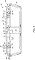
- FIG. 4 a cross sectional view of the cover assembly 102 along a plane A-A' (shown in FIGS. 1-3 ) is illustrated.
- the locking tabs 204, 208 will be explained in more detail.
- a configuration of each of the other locking tabs 206, 210, 212, 214 is similar to the configuration of the locking tabs 204, 208.
- Each of the locking tabs 204, 208 includes a substantially elongated configuration defining a height " H " thereof.
- the height " H " of each of the plurality of locking tabs 204, 206, 208, 210, 212, 214 is equal to one another. In other embodiments, the height " H " of one or more of the plurality of locking tabs 204, 206, 208, 210, 212, 214 may be different with respect to one another.
- Each of the locking tabs 204, 208 includes a stem portion 402, 404 and an enlarged portion 406, 408 connected to the stem portion 402, 404 respectively.
- the stem portion 402, 404 is connected to the second side 202 of the cover plate 106.
- the enlarged portion 406, 408 is disposed on the stem portion 402, 404 respectively in a manner such that the enlarged portion 406, 408 is distal with respect to the second side 202 of the cover plate 106.
- the stem portion 402, 404 includes a substantially cylindrical configuration and the enlarged portion 406, 408 includes a substantially spherical configuration. Accordingly, a diameter " DE " of the enlarged portion 406, 408 is substantially greater with respect to a diameter " DS " of the stem portion 402, 404.
- the stem portion 402, 404 and/or the enlarged portion 406, 408 may include any other configuration known in the art, such as a substantially flatter configuration.
- the second side 202 of the cover plate 106 also includes at least one centering geometry extending away therefrom. More specifically, the second side 202 includes a plurality of centering geometries 216, 218 provided thereon. Each of the plurality of centering geometries 216, 218 is disposed spaced apart from one another. In the illustrated embodiment, the second side 202 includes two centering geometries 216, 218 provided thereon and disposed spaced apart from one another. In other embodiments, the second side 202 may include a single or multiple centering geometries based on application requirements.
- Each of the plurality of centering geometries 216, 218 includes a first protrusion 220, 222 and a second protrusion 224, 226 respectively.
- Each of the first protrusion 220, 222 and the second protrusion 224, 226 extends away from the second side 202 of the cover plate 106.
- each of the first protrusion 220, 222 and the second protrusion 224, 226 intersects one another respectively.
- each of the first protrusion 220, 222 and the second protrusion 224, 226 intersects perpendicularly with one another respectively.
- each of the first protrusion 220, 222 and the second protrusion 224, 226 may intersect one another respectively at any other angular value based on application requirements.
- Each of the first protrusions 220, 222 includes an elongated configuration defining a height " H1 ", “ H2 “ and a width “ W1 “, “ W2 “ respectively.
- Each of the second protrusions 224, 226 also includes an elongated configuration defining a height “ H3 “, “ H4 “ and a width “ W3 “, “ W4 “ respectively.
- the height " H1 “, “ H2 “, “ H3 “, “ H4 " of each of the first protrusions 220, 222 and the second protrusions 224, 226 respectively is equal to one another.
- each of the first protrusions 220, 222 and the second protrusions 224, 226 respectively is substantially greater with respect to the height " H " of each of the plurality of locking tabs 204, 206, 208, 210, 212, 214.
- any undesired lateral force resulting due to incorrect alignment of the cover plate 106 with respect to the base plate 302 may be taken up by the plurality of centering geometries 216, 218 instead of the plurality of locking tabs 204, 206, 208, 210, 212, 214. This may limit breakage of one or more of the plurality of locking tabs 204, 206, 208, 210, 212, 214 during assembly of the cover plate 106.
- the height " H1 “, “ H2 “, “ H3 “, “ H4 “ of one or more of the first protrusions 220, 222 and/or the second protrusions 224, 226 respectively may be different with respect to one another.
- the width " W1 “, “ W2 “, “ W3 “, “ W4 " of each of the first protrusions 220 , 222 and the second protrusions 224 , 226 respectively is different with respect to one another.
- the width " W1 ", " W2 “, “ W3 “, “ W4 " of one or more of the first protrusion 220, 222 and/or the second protrusion 224, 226 respectively may be equal with respect to one another.
- the cover plate 106 also includes a first reinforcing rib 228 provide thereon. More specifically, the first reinforcing rib 228 is provided extending, at least partially, along the second side 202 of the cover plate 106.
- the first reinforcing rib 228 includes a first pair of reinforcing ribs 230 and a second pair of reinforcing ribs 232.
- the first pair of reinforcing ribs 230 extends along the second side 202 of the cover plate 106 forming a substantially C-shaped configuration.
- the second pair of reinforcing ribs 232 extends along the second side 202 of the cover plate 106 forming a substantially square shaped configuration.
- the first pair of reinforcing ribs 230 and the second pair of reinforcing ribs 232 are provided in contact with one another.
- the first reinforcing rib 228 including the first pair of reinforcing ribs 230 and the second pair of reinforcing ribs 232 is adapted to provide structural rigidity to the cover plate 106 against flexing.
- the configuration of the first reinforcing rib 228 including the first pair of reinforcing ribs 230 and the second pair of reinforcing ribs 232 described herein is merely exemplary and may vary based on application requirements.
- the first reinforcing rib 228 may include any other configuration, such as a triangular configuration, a linear configuration, a circular configuration, a serpentine configuration, and so on.
- the cover plate 106 also includes a grooved protrusion 234 extending from the second side 202 thereof.
- the grooved protrusion 234 is provided in contact with the first reinforcing rib 228, and more specifically with the second pair of reinforcing ribs 232.
- the grooved protrusion 234 includes a plurality of grooves 236 provided therein. Each of the plurality of grooves 236 is spaced apart with respect to one another.
- the grooved protrusion 234 includes four grooves 236. In other embodiments, the grooved protrusion 234 may include a single or multiple grooves based on application requirements. Each of the plurality of grooves 236 of the grooved protrusion 234 is adapted to receive a cable (not shown) therein. The grooved protrusion 234 provides improved cable management, reduced bending stress, and in turn limits structural damage to the cables entering/exiting the device 100.
- the cover plate 106 also includes a curved edge 238 extending along a periphery 240 thereof. Referring to FIG. 4 , the curved edge 238 extends from the first side 108 towards the second side 202 defining a radius of curvature " R “ thereof. Also, the curved edge 238 defines an overall height " HC “ of the cover plate 106.
- the overall height " HC " is approximately equal with respect to the height " H " of each of the plurality of locking tabs 204, 206, 208, 210, 212, 214 respectively. In other embodiments, the overall height " HC " may be smaller or greater with respect to the height " H " of each of the plurality of locking tabs 204, 206, 208, 210, 212, 214 respectively based on application requirements.
- the cover assembly 102 also includes the base plate 302.
- the base plate 302 is removably affixed to the base portion 104 using one or more fastening elements (not shown), such as screws, bolts, tabs, clips, and so on.
- the base plate 302 includes a substantially planar configuration defining a periphery 304 thereof.
- an overall configuration of the base plate 302 is similar to the overall configuration of the cover plate 106 and the base portion 104.
- the base plate 302 is sized partially smaller with respect to a size of the cover plate 106. Accordingly, in the assembled position of the cover assembly 102, a portion 112 (shown in FIGS. 1 and 2 ) of the cover plate 106 extends laterally over the periphery 304 of the base plate 302.
- the cover plate 106 may be contacted around the portion 112 by the user in order to lift the cover plate 106 with respect to the base plate 302.
- the complete periphery 240 of the cover plate 106 may extend laterally with respect to the periphery 304 of the base plate 302. In such a situation, the cover plate 106 may be contacted anywhere around the periphery 240 thereof by the user in order to lift the cover plate 106 with respect to the base plate 302.
- the base portion 104 includes a notch 306 provided extending, at least partially, along the periphery 304 thereof.
- the notch 306 is provided in association with the portion 112 and the grooved protrusion 234 of the cover plate 106.
- the notch 306 provides a recess 114 (shown in FIGS. 1 and 3 ) between the periphery 240 of the cover plate 106 and the periphery 304 of the base plate 302.
- the recess 114 is adapted to receive one or more fingers of the user or any contacting element such as a coin in order to grip or contact the portion 112 of the cover plate 106 respectively. Accordingly, a force may be applied around the portion 112 in order to separate the cover plate 106 with respect to the base plate 302.
- the base plate 302 also includes at least one tab receiving portion provided thereon.
- the at least one tab receiving portion is provided in association with the at least one locking tab provided on the cover plate 106.
- the base plate 302 includes a plurality of tab receiving portions 308, 310, 312, 314, 316, 318 provided thereon.
- Each of the plurality of tab receiving portions 308, 310, 312, 314, 316, 318 is provided in association with each of the plurality of locking tabs 204, 206, 208, 210, 212, 214 respectively.
- Each of the plurality of tab receiving portions 308, 310, 312, 314, 316, 318 includes a substantially hollow and spherical configuration.
- each of the plurality of tab receiving portions 308, 310, 312, 314, 316, 318 is disposed spaced apart from one another.
- the base plate 302 includes six tab receiving portions 308, 310, 312, 314, 316, 318 provided thereon and disposed spaced apart from one another.
- the base plate 302 may include a single or multiple tab receiving portions based on application requirements.
- each of the plurality of tab receiving portions 308, 310, 312, 314, 316, 318 is adapted to receive each of the plurality of locking tabs 204, 206, 208, 210, 212, 214 respectively in order to removably affix the cover plate 106 with respect to the base plate 302.
- each of the tab receiving portions 308, 312 is substantially raised with respect to a surface 320 of the base plate 302 defining a height " H5 " thereof.
- the raised configuration provides a visual indication to the user to correctly align each of the tab receiving portions 308, 312 with respect to each of the locking tabs 204, 208 respectively during assembly.
- the height " H5 " is approximately equal to the diameter " DE " of the enlarged portion 406, 408 of each of the locking tabs 204, 208.
- the configuration of each of the tab receiving portions 308, 312 is similar to the configuration of the enlarged portions 406, 408 of each of the locking tabs 204, 208 respectively. Accordingly, during assembly, the enlarged portion 406, 408 of each of the locking tabs 204, 208 is adapted to be snapped in to each of the tab receiving portions 308, 312 respectively.
- the snapping effect provides a haptical feedback to the user with respect to each of the plurality of locking tabs 204, 206, 208, 210, 212, 214 being received and removably locked within each of the plurality of tab receiving portions 308, 310, 312, 314, 316, 318 respectively.
- the base plate 302 also includes at least one receiving portion provided thereon.
- the at least one receiving portion is provided in association with the at least one centering geometry provided on the cover plate 106. More specifically, the base plate 302 includes a plurality of receiving portions 322, 324 provided thereon. Each of the plurality of receiving portions 322, 324 is provided in association with each of the plurality of centering geometries 216, 218 respectively. Each of the plurality of receiving portions 322, 324 includes a substantially hollow and oval configuration.
- each of the plurality of receiving portions 322, 324 is disposed spaced apart from one another.
- the base plate 302 includes two receiving portions 322, 324 provided thereon and disposed spaced apart from one another.
- the base plate 302 may include a single or multiple receiving portions based on application requirements.
- each of the plurality of receiving portions 322, 324 is adapted to receive each of the plurality of centering geometries 216, 218 respectively to align the cover plate 106 with respect to the base plate 302.
- each of the plurality of receiving portions 322, 324 is oriented differently with respect to one another.
- the receiving portion 322 is oriented along an axis X-X' and the receiving portion 324 is oriented along an axis Y-Y' .
- the orientation of each of the plurality of receiving portions 322, 324 with respect to one another is based on difference of the width " W1 ", " W2 ", “ W3 “, “ W4 " of each of the first protrusions 220 , 222 and the second protrusions 224 , 226 of each of the plurality of centering geometries 216 , 218 respectively.
- the differently oriented each of the plurality of receiving portions 322, 324 provides a visual indication to the user and a poka-yoke feature in order to correctly align the cover plate 106 with respect to the base plate 302 during assembly.
- the base plate 302 also includes a second reinforcing rib 326 provided thereon. More specifically, the second reinforcing rib 326 is provided extending, at least partially, along the surface 320 of the base plate 302.
- the second reinforcing rib 326 includes a first auxiliary rib 328 and a second auxiliary rib 330.
- the first auxiliary rib 328 and the second auxiliary rib 330 is provided in association with the first pair of reinforcing ribs 230 and the second pair of reinforcing ribs 232 provided on the cover plate 106 respectively
- first auxiliary rib 328 extends along the surface 320 of the base plate 302 forming a substantially C-shaped configuration.
- the second auxiliary rib 330 extends along the surface 320 of the base plate 302 forming a substantially square shaped configuration.
- the first auxiliary rib 328 and the second auxiliary rib 330 are adapted to provide structural rigidity to the base plate 302 against flexing.
- the configuration of the second reinforcing rib 326 described herein is merely exemplary and may vary based on the configuration of the first reinforcing rib 228 provided on the cover plate 106.
- the first auxiliary rib 328 is adapted to be received within the first pair of reinforcing ribs 230 provided on the cover plate 106.
- the second auxiliary rib 330 is adapted to be received within the second pair of reinforcing ribs 232 provided on the cover plate 106.
- the base plate 302 also includes an edge 332 extending along the periphery 304 thereof. Referring to FIG. 4 , in the assembled position of the cover assembly 102, the edge 332 is adapted to contact the curved edge 238 of the cover plate 106. As such, in the assembled position, the cover plate 106 in association with the base plate 302 provides an enclosure in order to limit accidental touch to internal components of the device 100 and/or entry of foreign material such as dust, moisture, and so on within the device 100.
- the plurality of locking tabs 204, 206, 208, 210, 212, 214 is provided on the second side 202 of the cover plate 106 whereas the plurality of tab receiving portions 308, 310, 312, 314, 316, 318 is provided on the base plate 302.
- an arrangement of the plurality of locking tabs 204, 206, 208, 210, 212, 214 and the plurality of tab receiving portions 308, 310, 312, 314, 316, 318 may be reversed such that the plurality of locking tabs 204, 206, 208, 210, 212, 214 may be provided on the base plate 302 whereas the plurality of tab receiving portions 308, 310, 312, 314, 316, 318 may be provided on the second side 202 of the cover plate 106.
- one or more of the plurality of locking tabs 204, 206, 208, 210, 212, 214 may be provided on the second side 202 of the cover plate 106 and the remaining of the plurality of locking tabs 204, 206, 208, 210, 212, 214 may be provided on the base plate 302.
- one or more of the plurality of tab receiving portions 308, 310, 312, 314, 316, 318 may be provided on the base plate 302 and the remaining of the plurality of tab receiving portions 308, 310, 312, 314, 316, 318 may be provided on the second side 202 of the cover plate 106.
- the plurality of centering geometries 216, 218 is provided on the second side 202 of the cover plate 106 whereas the plurality of receiving portions 322, 324 is provided on the base plate 302. It should be noted that in other embodiments, an arrangement of the plurality of centering geometries 216, 218 and the plurality of receiving portions 322, 324 may be reversed such that the plurality of centering geometries 216, 218 may be provided on the base plate 302 whereas the plurality of receiving portions 322, 324 may be provided on the second side 202 of the cover plate 106.
- one or more of the plurality of centering geometries 216, 218 may be provided on the second side 202 of the cover plate 106 and the remaining of the plurality of centering geometries 216, 218 may be provided on the base plate 302.
- one or more of the plurality of receiving portions 322, 324 may be provided on the base plate 302 and the remaining of the plurality of receiving portions 322, 324 may be provided on the second side 202 of the cover plate 106.
Landscapes
- Engineering & Computer Science (AREA)
- Microelectronics & Electronic Packaging (AREA)
- Casings For Electric Apparatus (AREA)
Claims (15)
- Werkzeuglose Abdeckungsanordnung (102) für ein elektrisches oder elektronisches Gerät (100), wobei die werkzeuglose Abdeckungsanordnung (102) umfasst:eine Grundplatte (302);einen Grundabschnitt (104), der ausgelegt ist, die Grundplatte (302) aufzunehmen und geeignet ist, ein oder mehrere Elemente zu umschließen;eine Abdeckplatte (106), die ausgelegt ist, um abnehmbar an der Grundplatte (302) befestigt zu werden;eine Aussparung (306), die in der Grundplatte (302) und in Verbindung mit der Abdeckplatte (106) vorgesehen ist, wobei die Aussparung (306) angepasst ist, um eine Aussparung (114) zwischen der Grundplatte (302) und der Abdeckplatte (106) in einer zusammengesetzten Position bereitzustellen;dadurch gekennzeichnet, dass:ein Umfang (240) der Abdeckplatte (106) sich über einen Umfang (304) der Grundplatte (302) erstreckt, so dass die Abdeckplatte (106) durch Berühren eines Abschnitts (112) der Abdeckplatte (106) durch einen Benutzer angehoben werden kann;wobei die Abdeckplatte (106) eine einzelne oder mehrere optische Anzeigen (110) umfasst.
- Werkzeuglose Abdeckungsanordnung (102) nach Anspruch 1, wobei die Aussparung (114) zur Aufnahme eines oder mehrerer Finger des Benutzers ausgelegt ist.
- Werkzeuglose Abdeckungsanordnung (102) nach Anspruch 1 und 2, ferner umfassend:mindestens eine Verriegelungslasche, die sich von mindestens einer der Abdeckplatte (106) und der Grundplatte (302) weg erstreckt; undmindestens einen Laschenaufnahmeabschnitt, der an mindestens einer von der Grundplatte (302) und der Abdeckplatte (106) und in Verbindung mit der jeweils mindestens einen Verriegelungslasche vorgesehen ist, wobei der mindestens eine Laschenaufnahmeabschnitt ausgelegt ist, um die mindestens eine Verriegelungslasche darin entfernbar aufzunehmen, um die Abdeckplatte (106) in Bezug auf die Grundplatte (302) abnehmbar zu befestigen.
- Werkzeuglose Abdeckungsanordnung (102) nach Anspruch 1-3, wobei:die mindestens eine Verriegelungslasche eine Vielzahl von Verriegelungslaschen (204, 206, 208, 210, 212, 214) umfasst, wobei jede der Vielzahl von Verriegelungslaschen (204, 206, 208, 210, 212, 214) mit Abstand zueinander angeordnet ist; undder mindestens eine Laschenaufnahmeabschnitt eine Vielzahl von Laschenaufnahmeabschnitten (308, 310, 312, 314, 316, 318) umfasst, wobei jeder der Vielzahl von Laschenaufnahmeabschnitten (308, 310, 312, 314, 316, 318) in Bezug zueinander beabstandet und in Zuordnung zu jeder der Vielzahl von Verriegelungslaschen (204, 206, 208, 210, 212, 214) angeordnet ist.
- Werkzeuglose Abdeckungsanordnung (102) nach Anspruch 4, wobei die mindestens eine Verriegelungslasche einen vergrößerten Abschnitt (406, 408) an einem distalen Ende umfasst, wobei der vergrößerte Abschnitt (406, 408) so ausgelegt ist, dass er in den mindestens einen Laschenaufnahmeabschnitt eingeschnappt werden kann.
- Werkzeuglose Abdeckungsanordnung (102) nach Anspruch 4 und 5, wobei eine Höhe (H) der mindestens einen Verriegelungslasche gleich einer Gesamthöhe (HC) der Abdeckplatte (106) ist.
- Werkzeuglose Abdeckungsanordnung (102) nach Anspruch 1, ferner umfassend:mindestens eine Zentriergeometrie, die sich von mindestens einer der Abdeckplatte (106) und der Grundplatte (302) weg erstreckt; undmindestens einen Aufnahmeabschnitt, der an mindestens einer von der Grundplatte (302) und der Abdeckplatte (106) und in Verbindung mit der jeweils mindestens einen Zentriergeometrie vorgesehen ist, wobei der mindestens eine Aufnahmeabschnitt ausgelegt ist, die mindestens eine Zentriergeometrie abnehmbar aufzunehmen, um die Abdeckplatte (106) in Bezug auf die Grundplatte (302) auszurichten.
- Werkzeuglose Abdeckungsanordnung (102) nach Anspruch 7, wobei die mindestens eine Zentriergeometrie einen ersten Vorsprung (220, 222) und einen zweiten Vorsprung (224, 226) umfasst, der den ersten Vorsprung (220, 222) schneidet.
- Werkzeuglose Abdeckungsanordnung (102) nach Anspruch 8, wobei der erste Vorsprung (220, 222) den zweiten Vorsprung (224, 226) perpendikular schneidet.
- Werkzeuglose Abdeckungsanordnung (102) nach Anspruch 7, wobei:die mindestens eine Zentriergeometrie eine Vielzahl von Zentriergeometrien (216, 218) umfasst, wobei jede der Vielzahl von Zentriergeometrien (216, 218) in Bezug zueinander beabstandet angeordnet ist; undder mindestens eine Aufnahmeabschnitt eine Vielzahl von Aufnahmeabschnitten (322, 324) umfasst, wobei jeder der Vielzahl von Aufnahmeabschnitten (322, 324) beabstandet in Bezug zueinander und in Zuordnung zu jeder der Vielzahl von Zentriergeometrien (216, 218) angeordnet ist.
- Werkzeuglose Abdeckungsanordnung (102) nach Anspruch 7, wobei eine Abmessung von mindestens einer der Vielzahl von Zentriergeometrien (216, 218) in Bezug auf die übrigen der Vielzahl von Zentriergeometrien (216, 218) unterschiedlich ist.
- Werkzeuglose Abdeckungsanordnung (102) nach Anspruch 1-11, ferner umfassend:eine erste Verstärkungsrippe (228), die sich zumindest teilweise entlang einer Innenfläche der Abdeckplatte (106) erstreckt; undeine zweite Verstärkungsrippe (326), die sich zumindest teilweise entlang einer Oberfläche (320) der Grundplatte (302) und in Verbindung mit der ersten Verstärkungsrippe (228) erstreckt,wobei die erste Verstärkungsrippe (228) und die zweite Verstärkungsrippe (326) so ausgelegt sind, dass sie in einer zusammengesetzten Position der Abdeckplatte (106) in Bezug auf die Grundplatte (302) nebeneinander angeordnet sind.
- Werkzeuglose Abdeckungsanordnung (102) nach Anspruch 1-12, wobei die Abdeckplatte (106) einen gerippten Vorsprung (234) aufweist, der sich von ihrer Innenfläche aus erstreckt, wobei der gerippte Vorsprung (234) in Verbindung mit der in der Grundplatte (302) vorgesehenen Aussparung (306) vorgesehen ist, wobei der gerippte Vorsprung (234) dazu geeignet ist, ein oder mehrere Kabel abnehmbar aufzunehmen.
- Werkzeuglose Abdeckungsanordnung (102) nach Anspruch 1-13, wobei die Grundplatte (302) und die Abdeckungsplatte (106) jeweils eine Kante (238, 332) aufweisen, wobei die Kanten (238, 332) so ausgelegt sind, dass sie sich in einer zusammengesetzten Position der Abdeckungsplatte (106) in Bezug auf die Grundplatte (302) zumindest teilweise gegenseitig berühren.
- Werkzeuglose Abdeckungsanordnung (102) nach Anspruch 1-14, wobei die Vorrichtung (100) eine Ventilsteuereinheit ist.
Applications Claiming Priority (2)
| Application Number | Priority Date | Filing Date | Title |
|---|---|---|---|
| DE102017002839 | 2017-03-24 | ||
| PCT/EP2018/052531 WO2018171966A1 (en) | 2017-03-24 | 2018-02-01 | Tool-less cover assembly |
Publications (2)
| Publication Number | Publication Date |
|---|---|
| EP3603357A1 EP3603357A1 (de) | 2020-02-05 |
| EP3603357B1 true EP3603357B1 (de) | 2021-03-31 |
Family
ID=61192895
Family Applications (1)
| Application Number | Title | Priority Date | Filing Date |
|---|---|---|---|
| EP18704479.7A Active EP3603357B1 (de) | 2017-03-24 | 2018-02-01 | Werkzeuglose abdeckungsanordnung |
Country Status (4)
| Country | Link |
|---|---|
| EP (1) | EP3603357B1 (de) |
| CN (1) | CN110140435B (de) |
| TW (1) | TWI750354B (de) |
| WO (1) | WO2018171966A1 (de) |
Family Cites Families (9)
| Publication number | Priority date | Publication date | Assignee | Title |
|---|---|---|---|---|
| US4431113A (en) * | 1982-12-07 | 1984-02-14 | Northern Telecom Limited | Cover attachment device |
| JP4158626B2 (ja) * | 2003-06-30 | 2008-10-01 | ソニー株式会社 | 外部記憶装置 |
| CN2750622Y (zh) * | 2004-11-22 | 2006-01-04 | 深圳富泰宏精密工业有限公司 | 便携式电子装置电池盖 |
| US8600043B2 (en) * | 2009-07-07 | 2013-12-03 | Blackberry Limited | Locking mechanism for a cover for a housing of an electronic device |
| TWM438097U (en) * | 2011-11-11 | 2012-09-21 | Wistron Corp | Electronic apparatus and the casing structure thereof |
| DE102013203195A1 (de) * | 2013-02-27 | 2014-08-28 | Robert Bosch Gmbh | Kunststoffelement mit Einrastelement |
| KR101776262B1 (ko) * | 2014-06-27 | 2017-09-11 | 삼성전자주식회사 | 접철식 기기 |
| CN204706981U (zh) * | 2015-07-06 | 2015-10-14 | 珠海格力电器股份有限公司 | 盖体装置 |
| CN204883613U (zh) * | 2015-07-09 | 2015-12-16 | 上海钛度智能科技有限公司 | 免工具快速拆装式鼠标 |
-
2018
- 2018-02-01 WO PCT/EP2018/052531 patent/WO2018171966A1/en not_active Ceased
- 2018-02-01 EP EP18704479.7A patent/EP3603357B1/de active Active
- 2018-02-01 CN CN201880005731.1A patent/CN110140435B/zh active Active
- 2018-03-19 TW TW107109305A patent/TWI750354B/zh not_active IP Right Cessation
Non-Patent Citations (1)
| Title |
|---|
| None * |
Also Published As
| Publication number | Publication date |
|---|---|
| CN110140435A (zh) | 2019-08-16 |
| CN110140435B (zh) | 2020-07-07 |
| WO2018171966A1 (en) | 2018-09-27 |
| TW201836455A (zh) | 2018-10-01 |
| EP3603357A1 (de) | 2020-02-05 |
| TWI750354B (zh) | 2021-12-21 |
Similar Documents
| Publication | Publication Date | Title |
|---|---|---|
| EP3282131A1 (de) | Aufbau von deckenlüfterschaufeln und deckenlüfter | |
| US8822859B2 (en) | Electrical device with subrocker and removable rocker | |
| EP3657605B1 (de) | Klemmleiste mit seitlichen elastischen griffen | |
| US20200083687A1 (en) | Quick connect | |
| US5696416A (en) | Mounting of motor for refrigeration | |
| EP3603357A1 (de) | Werkzeuglose abdeckungsanordnung | |
| US8485079B2 (en) | Angle cutting machine with exchangeable cutting members | |
| US4081629A (en) | Snap-in bracket for mounting a telephone dial within a telephone housing | |
| US20110063817A1 (en) | Switch/circuit board unit for installation in a handle of a hand-held tool | |
| EP3784914A1 (de) | Schnappverschlussbefestigungsmittel | |
| US20100140064A1 (en) | Rotary control switch mounted on control panel of electrical appliance | |
| CN215989072U (zh) | 电池安装组件以及开关 | |
| EP4268254B1 (de) | Abdeckvorrichtung für den knopf eines elektrischen moduls | |
| US7642472B2 (en) | Switch package assembly with mounting base adapter | |
| CN219738801U (zh) | 急停按钮保护罩及加工设备 | |
| CN222483171U (zh) | 用于开关面板设备的联排框组件及开关面板设备 | |
| KR20090049458A (ko) | 차량용 배터리 케이블 단자 | |
| CN222263036U (zh) | 一种电热毯控制器及电热毯 | |
| US12363835B2 (en) | Human interface module mounting device | |
| CN219678849U (zh) | 一种底座安装结构 | |
| EP4268337B1 (de) | Abdeckvorrichtung, die mit einem elektrischen modul kombinierbar ist | |
| CN106550778B (zh) | 手持式园艺器具、把手单元和主功能单元 | |
| CN222281828U (zh) | 按键帽固定装置和电视机 | |
| JP7541180B2 (ja) | 端子装置 | |
| CN216820320U (zh) | 集控盒 |
Legal Events
| Date | Code | Title | Description |
|---|---|---|---|
| STAA | Information on the status of an ep patent application or granted ep patent |
Free format text: STATUS: UNKNOWN |
|
| STAA | Information on the status of an ep patent application or granted ep patent |
Free format text: STATUS: THE INTERNATIONAL PUBLICATION HAS BEEN MADE |
|
| PUAI | Public reference made under article 153(3) epc to a published international application that has entered the european phase |
Free format text: ORIGINAL CODE: 0009012 |
|
| STAA | Information on the status of an ep patent application or granted ep patent |
Free format text: STATUS: REQUEST FOR EXAMINATION WAS MADE |
|
| 17P | Request for examination filed |
Effective date: 20190619 |
|
| AK | Designated contracting states |
Kind code of ref document: A1 Designated state(s): AL AT BE BG CH CY CZ DE DK EE ES FI FR GB GR HR HU IE IS IT LI LT LU LV MC MK MT NL NO PL PT RO RS SE SI SK SM TR |
|
| AX | Request for extension of the european patent |
Extension state: BA ME |
|
| DAV | Request for validation of the european patent (deleted) | ||
| DAX | Request for extension of the european patent (deleted) | ||
| GRAP | Despatch of communication of intention to grant a patent |
Free format text: ORIGINAL CODE: EPIDOSNIGR1 |
|
| STAA | Information on the status of an ep patent application or granted ep patent |
Free format text: STATUS: GRANT OF PATENT IS INTENDED |
|
| INTG | Intention to grant announced |
Effective date: 20210113 |
|
| GRAS | Grant fee paid |
Free format text: ORIGINAL CODE: EPIDOSNIGR3 |
|
| GRAA | (expected) grant |
Free format text: ORIGINAL CODE: 0009210 |
|
| STAA | Information on the status of an ep patent application or granted ep patent |
Free format text: STATUS: THE PATENT HAS BEEN GRANTED |
|
| AK | Designated contracting states |
Kind code of ref document: B1 Designated state(s): AL AT BE BG CH CY CZ DE DK EE ES FI FR GB GR HR HU IE IS IT LI LT LU LV MC MK MT NL NO PL PT RO RS SE SI SK SM TR |
|
| REG | Reference to a national code |
Ref country code: GB Ref legal event code: FG4D Ref country code: CH Ref legal event code: EP |
|
| REG | Reference to a national code |
Ref country code: AT Ref legal event code: REF Ref document number: 1378457 Country of ref document: AT Kind code of ref document: T Effective date: 20210415 |
|
| REG | Reference to a national code |
Ref country code: DE Ref legal event code: R096 Ref document number: 602018014720 Country of ref document: DE |
|
| REG | Reference to a national code |
Ref country code: IE Ref legal event code: FG4D |
|
| REG | Reference to a national code |
Ref country code: LT Ref legal event code: MG9D |
|
| PG25 | Lapsed in a contracting state [announced via postgrant information from national office to epo] |
Ref country code: HR Free format text: LAPSE BECAUSE OF FAILURE TO SUBMIT A TRANSLATION OF THE DESCRIPTION OR TO PAY THE FEE WITHIN THE PRESCRIBED TIME-LIMIT Effective date: 20210331 Ref country code: FI Free format text: LAPSE BECAUSE OF FAILURE TO SUBMIT A TRANSLATION OF THE DESCRIPTION OR TO PAY THE FEE WITHIN THE PRESCRIBED TIME-LIMIT Effective date: 20210331 Ref country code: BG Free format text: LAPSE BECAUSE OF FAILURE TO SUBMIT A TRANSLATION OF THE DESCRIPTION OR TO PAY THE FEE WITHIN THE PRESCRIBED TIME-LIMIT Effective date: 20210630 Ref country code: NO Free format text: LAPSE BECAUSE OF FAILURE TO SUBMIT A TRANSLATION OF THE DESCRIPTION OR TO PAY THE FEE WITHIN THE PRESCRIBED TIME-LIMIT Effective date: 20210630 |
|
| PG25 | Lapsed in a contracting state [announced via postgrant information from national office to epo] |
Ref country code: RS Free format text: LAPSE BECAUSE OF FAILURE TO SUBMIT A TRANSLATION OF THE DESCRIPTION OR TO PAY THE FEE WITHIN THE PRESCRIBED TIME-LIMIT Effective date: 20210331 Ref country code: LV Free format text: LAPSE BECAUSE OF FAILURE TO SUBMIT A TRANSLATION OF THE DESCRIPTION OR TO PAY THE FEE WITHIN THE PRESCRIBED TIME-LIMIT Effective date: 20210331 Ref country code: SE Free format text: LAPSE BECAUSE OF FAILURE TO SUBMIT A TRANSLATION OF THE DESCRIPTION OR TO PAY THE FEE WITHIN THE PRESCRIBED TIME-LIMIT Effective date: 20210331 |
|
| REG | Reference to a national code |
Ref country code: NL Ref legal event code: MP Effective date: 20210331 |
|
| REG | Reference to a national code |
Ref country code: AT Ref legal event code: MK05 Ref document number: 1378457 Country of ref document: AT Kind code of ref document: T Effective date: 20210331 |
|
| PG25 | Lapsed in a contracting state [announced via postgrant information from national office to epo] |
Ref country code: SM Free format text: LAPSE BECAUSE OF FAILURE TO SUBMIT A TRANSLATION OF THE DESCRIPTION OR TO PAY THE FEE WITHIN THE PRESCRIBED TIME-LIMIT Effective date: 20210331 Ref country code: NL Free format text: LAPSE BECAUSE OF FAILURE TO SUBMIT A TRANSLATION OF THE DESCRIPTION OR TO PAY THE FEE WITHIN THE PRESCRIBED TIME-LIMIT Effective date: 20210331 Ref country code: AT Free format text: LAPSE BECAUSE OF FAILURE TO SUBMIT A TRANSLATION OF THE DESCRIPTION OR TO PAY THE FEE WITHIN THE PRESCRIBED TIME-LIMIT Effective date: 20210331 Ref country code: LT Free format text: LAPSE BECAUSE OF FAILURE TO SUBMIT A TRANSLATION OF THE DESCRIPTION OR TO PAY THE FEE WITHIN THE PRESCRIBED TIME-LIMIT Effective date: 20210331 Ref country code: CZ Free format text: LAPSE BECAUSE OF FAILURE TO SUBMIT A TRANSLATION OF THE DESCRIPTION OR TO PAY THE FEE WITHIN THE PRESCRIBED TIME-LIMIT Effective date: 20210331 Ref country code: EE Free format text: LAPSE BECAUSE OF FAILURE TO SUBMIT A TRANSLATION OF THE DESCRIPTION OR TO PAY THE FEE WITHIN THE PRESCRIBED TIME-LIMIT Effective date: 20210331 |
|
| PG25 | Lapsed in a contracting state [announced via postgrant information from national office to epo] |
Ref country code: SK Free format text: LAPSE BECAUSE OF FAILURE TO SUBMIT A TRANSLATION OF THE DESCRIPTION OR TO PAY THE FEE WITHIN THE PRESCRIBED TIME-LIMIT Effective date: 20210331 Ref country code: RO Free format text: LAPSE BECAUSE OF FAILURE TO SUBMIT A TRANSLATION OF THE DESCRIPTION OR TO PAY THE FEE WITHIN THE PRESCRIBED TIME-LIMIT Effective date: 20210331 Ref country code: PT Free format text: LAPSE BECAUSE OF FAILURE TO SUBMIT A TRANSLATION OF THE DESCRIPTION OR TO PAY THE FEE WITHIN THE PRESCRIBED TIME-LIMIT Effective date: 20210802 Ref country code: PL Free format text: LAPSE BECAUSE OF FAILURE TO SUBMIT A TRANSLATION OF THE DESCRIPTION OR TO PAY THE FEE WITHIN THE PRESCRIBED TIME-LIMIT Effective date: 20210331 Ref country code: IS Free format text: LAPSE BECAUSE OF FAILURE TO SUBMIT A TRANSLATION OF THE DESCRIPTION OR TO PAY THE FEE WITHIN THE PRESCRIBED TIME-LIMIT Effective date: 20210731 |
|
| REG | Reference to a national code |
Ref country code: DE Ref legal event code: R097 Ref document number: 602018014720 Country of ref document: DE |
|
| PG25 | Lapsed in a contracting state [announced via postgrant information from national office to epo] |
Ref country code: AL Free format text: LAPSE BECAUSE OF FAILURE TO SUBMIT A TRANSLATION OF THE DESCRIPTION OR TO PAY THE FEE WITHIN THE PRESCRIBED TIME-LIMIT Effective date: 20210331 Ref country code: DK Free format text: LAPSE BECAUSE OF FAILURE TO SUBMIT A TRANSLATION OF THE DESCRIPTION OR TO PAY THE FEE WITHIN THE PRESCRIBED TIME-LIMIT Effective date: 20210331 Ref country code: ES Free format text: LAPSE BECAUSE OF FAILURE TO SUBMIT A TRANSLATION OF THE DESCRIPTION OR TO PAY THE FEE WITHIN THE PRESCRIBED TIME-LIMIT Effective date: 20210331 |
|
| PLBE | No opposition filed within time limit |
Free format text: ORIGINAL CODE: 0009261 |
|
| STAA | Information on the status of an ep patent application or granted ep patent |
Free format text: STATUS: NO OPPOSITION FILED WITHIN TIME LIMIT |
|
| 26N | No opposition filed |
Effective date: 20220104 |
|
| PGFP | Annual fee paid to national office [announced via postgrant information from national office to epo] |
Ref country code: GB Payment date: 20220105 Year of fee payment: 5 |
|
| PG25 | Lapsed in a contracting state [announced via postgrant information from national office to epo] |
Ref country code: IS Free format text: LAPSE BECAUSE OF FAILURE TO SUBMIT A TRANSLATION OF THE DESCRIPTION OR TO PAY THE FEE WITHIN THE PRESCRIBED TIME-LIMIT Effective date: 20210731 |
|
| PGFP | Annual fee paid to national office [announced via postgrant information from national office to epo] |
Ref country code: FR Payment date: 20220107 Year of fee payment: 5 |
|
| PG25 | Lapsed in a contracting state [announced via postgrant information from national office to epo] |
Ref country code: IT Free format text: LAPSE BECAUSE OF FAILURE TO SUBMIT A TRANSLATION OF THE DESCRIPTION OR TO PAY THE FEE WITHIN THE PRESCRIBED TIME-LIMIT Effective date: 20210331 |
|
| PG25 | Lapsed in a contracting state [announced via postgrant information from national office to epo] |
Ref country code: MC Free format text: LAPSE BECAUSE OF FAILURE TO SUBMIT A TRANSLATION OF THE DESCRIPTION OR TO PAY THE FEE WITHIN THE PRESCRIBED TIME-LIMIT Effective date: 20210331 |
|
| REG | Reference to a national code |
Ref country code: CH Ref legal event code: PL |
|
| REG | Reference to a national code |
Ref country code: BE Ref legal event code: MM Effective date: 20220228 |
|
| PG25 | Lapsed in a contracting state [announced via postgrant information from national office to epo] |
Ref country code: LU Free format text: LAPSE BECAUSE OF NON-PAYMENT OF DUE FEES Effective date: 20220201 |
|
| PG25 | Lapsed in a contracting state [announced via postgrant information from national office to epo] |
Ref country code: LI Free format text: LAPSE BECAUSE OF NON-PAYMENT OF DUE FEES Effective date: 20220228 Ref country code: IE Free format text: LAPSE BECAUSE OF NON-PAYMENT OF DUE FEES Effective date: 20220201 Ref country code: CH Free format text: LAPSE BECAUSE OF NON-PAYMENT OF DUE FEES Effective date: 20220228 |
|
| PG25 | Lapsed in a contracting state [announced via postgrant information from national office to epo] |
Ref country code: BE Free format text: LAPSE BECAUSE OF NON-PAYMENT OF DUE FEES Effective date: 20220228 |
|
| P01 | Opt-out of the competence of the unified patent court (upc) registered |
Effective date: 20230419 |
|
| GBPC | Gb: european patent ceased through non-payment of renewal fee |
Effective date: 20230201 |
|
| PG25 | Lapsed in a contracting state [announced via postgrant information from national office to epo] |
Ref country code: GB Free format text: LAPSE BECAUSE OF NON-PAYMENT OF DUE FEES Effective date: 20230201 |
|
| PG25 | Lapsed in a contracting state [announced via postgrant information from national office to epo] |
Ref country code: GB Free format text: LAPSE BECAUSE OF NON-PAYMENT OF DUE FEES Effective date: 20230201 Ref country code: FR Free format text: LAPSE BECAUSE OF NON-PAYMENT OF DUE FEES Effective date: 20230228 |
|
| PG25 | Lapsed in a contracting state [announced via postgrant information from national office to epo] |
Ref country code: MK Free format text: LAPSE BECAUSE OF FAILURE TO SUBMIT A TRANSLATION OF THE DESCRIPTION OR TO PAY THE FEE WITHIN THE PRESCRIBED TIME-LIMIT Effective date: 20210331 Ref country code: CY Free format text: LAPSE BECAUSE OF FAILURE TO SUBMIT A TRANSLATION OF THE DESCRIPTION OR TO PAY THE FEE WITHIN THE PRESCRIBED TIME-LIMIT Effective date: 20210331 |
|
| PG25 | Lapsed in a contracting state [announced via postgrant information from national office to epo] |
Ref country code: HU Free format text: LAPSE BECAUSE OF FAILURE TO SUBMIT A TRANSLATION OF THE DESCRIPTION OR TO PAY THE FEE WITHIN THE PRESCRIBED TIME-LIMIT; INVALID AB INITIO Effective date: 20180201 |
|
| PG25 | Lapsed in a contracting state [announced via postgrant information from national office to epo] |
Ref country code: TR Free format text: LAPSE BECAUSE OF FAILURE TO SUBMIT A TRANSLATION OF THE DESCRIPTION OR TO PAY THE FEE WITHIN THE PRESCRIBED TIME-LIMIT Effective date: 20210331 |
|
| PG25 | Lapsed in a contracting state [announced via postgrant information from national office to epo] |
Ref country code: MT Free format text: LAPSE BECAUSE OF FAILURE TO SUBMIT A TRANSLATION OF THE DESCRIPTION OR TO PAY THE FEE WITHIN THE PRESCRIBED TIME-LIMIT Effective date: 20210331 |
|
| PG25 | Lapsed in a contracting state [announced via postgrant information from national office to epo] |
Ref country code: GR Free format text: LAPSE BECAUSE OF NON-PAYMENT OF DUE FEES Effective date: 20210331 |
|
| PG25 | Lapsed in a contracting state [announced via postgrant information from national office to epo] |
Ref country code: GR Free format text: LAPSE BECAUSE OF NON-PAYMENT OF DUE FEES Effective date: 20210331 |
|
| PGFP | Annual fee paid to national office [announced via postgrant information from national office to epo] |
Ref country code: DE Payment date: 20260109 Year of fee payment: 9 |