EP3603145B1 - Telekommunikationsvorrichtung und -verfahren - Google Patents
Telekommunikationsvorrichtung und -verfahren Download PDFInfo
- Publication number
- EP3603145B1 EP3603145B1 EP18712255.1A EP18712255A EP3603145B1 EP 3603145 B1 EP3603145 B1 EP 3603145B1 EP 18712255 A EP18712255 A EP 18712255A EP 3603145 B1 EP3603145 B1 EP 3603145B1
- Authority
- EP
- European Patent Office
- Prior art keywords
- network access
- access node
- terminal device
- security key
- master
- Prior art date
- Legal status (The legal status is an assumption and is not a legal conclusion. Google has not performed a legal analysis and makes no representation as to the accuracy of the status listed.)
- Active
Links
Images





Classifications
-
- H—ELECTRICITY
- H04—ELECTRIC COMMUNICATION TECHNIQUE
- H04L—TRANSMISSION OF DIGITAL INFORMATION, e.g. TELEGRAPHIC COMMUNICATION
- H04L63/00—Network architectures or network communication protocols for network security
- H04L63/06—Network architectures or network communication protocols for network security for supporting key management in a packet data network
- H04L63/062—Network architectures or network communication protocols for network security for supporting key management in a packet data network for key distribution, e.g. centrally by trusted party
-
- H—ELECTRICITY
- H04—ELECTRIC COMMUNICATION TECHNIQUE
- H04W—WIRELESS COMMUNICATION NETWORKS
- H04W12/00—Security arrangements; Authentication; Protecting privacy or anonymity
- H04W12/04—Key management, e.g. using generic bootstrapping architecture [GBA]
- H04W12/041—Key generation or derivation
-
- H—ELECTRICITY
- H04—ELECTRIC COMMUNICATION TECHNIQUE
- H04W—WIRELESS COMMUNICATION NETWORKS
- H04W12/00—Security arrangements; Authentication; Protecting privacy or anonymity
- H04W12/04—Key management, e.g. using generic bootstrapping architecture [GBA]
- H04W12/043—Key management, e.g. using generic bootstrapping architecture [GBA] using a trusted network node as an anchor
- H04W12/0433—Key management protocols
-
- H—ELECTRICITY
- H04—ELECTRIC COMMUNICATION TECHNIQUE
- H04W—WIRELESS COMMUNICATION NETWORKS
- H04W12/00—Security arrangements; Authentication; Protecting privacy or anonymity
- H04W12/06—Authentication
-
- H—ELECTRICITY
- H04—ELECTRIC COMMUNICATION TECHNIQUE
- H04W—WIRELESS COMMUNICATION NETWORKS
- H04W12/00—Security arrangements; Authentication; Protecting privacy or anonymity
- H04W12/08—Access security
-
- H—ELECTRICITY
- H04—ELECTRIC COMMUNICATION TECHNIQUE
- H04W—WIRELESS COMMUNICATION NETWORKS
- H04W36/00—Hand-off or reselection arrangements
- H04W36/0005—Control or signalling for completing the hand-off
- H04W36/0055—Transmission or use of information for re-establishing the radio link
- H04W36/0069—Transmission or use of information for re-establishing the radio link in case of dual connectivity, e.g. decoupled uplink/downlink
- H04W36/00692—Transmission or use of information for re-establishing the radio link in case of dual connectivity, e.g. decoupled uplink/downlink using simultaneous multiple data streams, e.g. cooperative multipoint [CoMP], carrier aggregation [CA] or multiple input multiple output [MIMO]
-
- H—ELECTRICITY
- H04—ELECTRIC COMMUNICATION TECHNIQUE
- H04L—TRANSMISSION OF DIGITAL INFORMATION, e.g. TELEGRAPHIC COMMUNICATION
- H04L2463/00—Additional details relating to network architectures or network communication protocols for network security covered by H04L63/00
- H04L2463/061—Additional details relating to network architectures or network communication protocols for network security covered by H04L63/00 applying further key derivation, e.g. deriving traffic keys from a pair-wise master key
-
- H—ELECTRICITY
- H04—ELECTRIC COMMUNICATION TECHNIQUE
- H04W—WIRELESS COMMUNICATION NETWORKS
- H04W88/00—Devices specially adapted for wireless communication networks, e.g. terminals, base stations or access point devices
- H04W88/08—Access point devices
Definitions
- the present disclosure relates to wireless telecommunications apparatus and methods.
- Third and fourth generation mobile telecommunication systems such as those based on the 3GPP defined UMTS and Long Term Evolution (LTE) architecture, are able to support more sophisticated services than simple voice and messaging services offered by previous generations of mobile telecommunication systems.
- LTE Long Term Evolution
- a user is able to enjoy high data rate applications such as mobile video streaming and mobile video conferencing that would previously only have been available via a fixed line data connection.
- the demand to deploy such networks is therefore strong and the coverage area of these networks, i.e. geographic locations where access to the networks is possible, may be expected to increase ever more rapidly.
- Future wireless communications networks will be expected to routinely and efficiently support communications with a wider range of devices associated with a wider range of data traffic profiles and types than current systems are optimised to support. For example it is expected future wireless communications networks will be expected to efficiently support communications with devices including reduced complexity devices, machine type communication devices, high resolution video displays, virtual reality headsets and so on.
- devices including reduced complexity devices, machine type communication devices, high resolution video displays, virtual reality headsets and so on.
- Some of these different types of devices may be deployed in very large numbers, for example low complexity devices for supporting the "The Internet of Things", and may typically be associated with the transmissions of relatively small amounts of data with relatively high latency tolerance.
- Other types of device for example supporting high-definition video streaming, may be associated with transmissions of relatively large amounts of data with relatively low latency tolerance.
- Yet other types of device may be characterised by data that should be transmitted through a network with very low latency and very high reliability.
- a single device type might also be associated with different data traffic profiles / characteristics depending on the application(s) it is running. For example, different consideration may apply for efficiently supporting data exchange with a smartphone when it is running a video streaming application (high downlink data) as compared to when it is running an Internet browsing application (sporadic uplink and downlink data) or being used for voice communications by an emergency responder in an emergency scenario.
- new radio access technology (RAT) systems / networks gives rise to new challenges for providing efficient operation for devices operating in new RAT networks, including devices able to operate in both new RAT networks (e.g. a 3GPP 5G network) and currently deployed RAT networks (e.g. a 3GPP 4G network).
- new RAT networks e.g. a 3GPP 5G network
- currently deployed RAT networks e.g. a 3GPP 4G network
- handovers between network nodes responsible for communicating with a terminal device, which may be referred to as mobility management. It will be appreciated handovers may result from a device physically moving between coverage areas of different cells or from changing radio conditions associated with different cells for a static device, and the term mobility management may be used for both scenarios.
- the 3GPP technical document "0ms interruption handover for NR" discusses how to reconfigure a user equipment (UE) from a master evolved node-B (MeNB) to a secondary evolved node-B (SeNB) to target 0 ms UP interruption.
- UE user equipment
- MeNB master evolved node-B
- SeNB secondary evolved node-B
- the document discusses the concept of role change between the M-gNB and S-gNB during handover.
- the 3GPP technical document "SeNB to MeNB reconfiguration for NR dual-connectivity" discusses how to reconfigure a user equipment (UE) from a master evolved node-B (MeNB) to a secondary evolved node-B (SeNB) to target 0 ms UP interruption.
- UE user equipment
- MeNB master evolved node-B
- SeNB secondary evolved node-B
- 0ms UP interruption for inter-frequency mobility can be achieved with dual connectivity for intra MeNB mobility.
- NR Mobility Enhancement on Dual Connectivity discusses how to reconfigure a user equipment (UE) from a master evolved node-B (MeNB) to a secondary evolved node-B (SeNB) to target 0 ms UP interruption.
- UE user equipment
- MeNB master evolved node-B
- SeNB secondary evolved node-B
- the document discusses the concept of make-before-break handover between eNBs.
- the 3GPP technical specification 3GPP TR 38.804, no. V14.0.0 from the the 3GPP radio access network technical specification group sets out some radio interface protocol aspects of new radio access technology.
- the present disclosure can help address or mitigate at least some of the issues discussed above.
- Figure 1 provides a schematic diagram illustrating some basic functionality of a mobile telecommunications network / system 100 operating generally in accordance with LTE principles, but which may also support other radio access technologies, and which may implement embodiments of the disclosure as described herein.
- Various elements of Figure 1 and certain aspects of their respective modes of operation are well-known and defined in the relevant standards administered by the 3GPP (RTM) body, and also described in many books on the subject, for example, Holma H. and Toskala A [2].
- the network 100 includes a plurality of base stations 101 connected to a core network 102.
- Each base station provides a coverage area 103 (i.e. a cell) within which data can be communicated to and from terminal devices 104.
- Data is transmitted from base stations 101 to terminal devices 104 within their respective coverage areas 103 via a radio downlink.
- Data is transmitted from terminal devices 104 to the base stations 101 via a radio uplink.
- the core network 102 routes data to and from the terminal devices 104 via the respective base stations 101 and provides functions such as authentication, mobility management, charging and so on.
- Terminal devices may also be referred to as mobile stations, user equipment (UE), user terminal, mobile radio, communications device, and so forth.
- Base stations which are an example of network infrastructure equipment / network access node, may also be referred to as transceiver stations / nodeBs / e-nodeBs, g-nodeBs and so forth.
- transceiver stations / nodeBs / e-nodeBs, g-nodeBs and so forth.
- different terminology is often associated with different generations of wireless telecommunications systems for elements providing broadly comparable functionality.
- certain embodiments of the disclosure may be equally implemented in different generations of wireless telecommunications systems, and for simplicity particular terminology may be used regardless of the underlying network architecture. That is to say, the use of a specific term in relation to certain example implementations is not intended to indicate these implementations are limited to a certain generation of network that may be most associated with that particular terminology.
- FIG. 2 is a schematic diagram illustrating a network architecture for a new RAT wireless mobile telecommunications network / system 300 based on previously proposed approaches which may also be adapted to provide functionality in accordance with embodiments of the disclosure described herein.
- the new RAT network 300 represented in Figure 2 comprises a first communication cell 301 and a second communication cell 302.
- Each communication cell 301, 302 comprises a controlling node (centralised unit) 321, 322 in communication with a core network component 310 over a respective wired or wireless link 351, 352.
- the respective controlling nodes 321, 322 are also each in communication with a plurality of distributed units (radio access nodes / remote transmission and reception points (TRPs)) 311, 312 in their respective cells.
- TRPs remote transmission and reception points
- the distributed units 311, 312 are responsible for providing the radio access interface for terminal devices connected to the network.
- Each distributed unit 311, 312 has a coverage area (radio access footprint) 341, 342 which together define the coverage of the respective communication cells 301, 302.
- the core network component 310 of the new RAT telecommunications system represented in Figure 2 may be broadly considered to correspond with the core network 102 represented in Figure 1
- the respective controlling nodes 321, 322 and their associated distributed units / TRPs 311, 312 may be broadly considered to provide functionality corresponding to base stations of Figure 1
- the term network infrastructure equipment / access node may be used to encompass these elements and more conventional base station type elements of wireless telecommunications systems.
- the responsibility for scheduling transmissions which are scheduled on the radio interface between the respective distributed units and the terminal devices may lie with the controlling node / centralised unit and / or the distributed units / TRPs.
- a terminal device 400 is represented in Figure 2 within the coverage area of the first communication cell 301. This terminal device 400 may thus exchange signalling with the first controlling node 321 in the first communication cell via one of the distributed units 311 associated with the first communication cell 301. In some cases communications for a given terminal device are routed through only one of the distributed units, but it will be appreciated in some other implementations communications associated with a given terminal device may be routed through more than one distributed unit, for example in a soft handover scenario and other scenarios.
- the particular distributed unit(s) through which a terminal device is currently connected through to the associated controlling node may be referred to as active distributed units for the terminal device.
- the active subset of distributed units for a terminal device may comprise one or more than one distributed unit (TRP).
- the controlling node 321 is responsible for determining which of the distributed units 311 spanning the first communication cell 301 is responsible for radio communications with the terminal device 400 at any given time (i.e. which of the distributed units are currently active distributed units for the terminal device). Typically this will be based on measurements of radio channel conditions between the terminal device 400 and respective ones of the distributed units 311. In this regard, it will be appreciated the subset of the distributed units in a cell which are currently active for a terminal device will depend, at least in part, on the location of the terminal device within the cell (since this contributes significantly to the radio channel conditions that exist between the terminal device and respective ones of the distributed units).
- two communication cells 301, 302 and one terminal device 400 are shown for simplicity, but it will of course be appreciated that in practice the system may comprise a larger number of communication cells (each supported by a respective controlling node and plurality of distributed units) serving a larger number of terminal devices.
- Figure 2 represents merely one example of a proposed architecture for a new RAT telecommunications system in which approaches in accordance with the principles described herein may be adopted, and the functionality disclosed herein may also be applied in respect of wireless telecommunications systems having different architectures.
- the network infrastructure equipment / access node may comprise a base station, such as an LTE-type base station 101 as shown in Figure 1 which is adapted to provide functionality in accordance with the principles described herein, and in other examples the network infrastructure equipment may comprise a control unit / controlling node 321, 322 and / or a TRP 311, 312 of the kind shown in Figure 2 which is adapted to provide functionality in accordance with the principles described herein.
- a base station such as an LTE-type base station 101 as shown in Figure 1 which is adapted to provide functionality in accordance with the principles described herein
- the network infrastructure equipment may comprise a control unit / controlling node 321, 322 and / or a TRP 311, 312 of the kind shown in Figure 2 which is adapted to provide functionality in accordance with the principles described herein.
- mobile communications networks such as the network 100 shown in Figure 1 and the network 300 shown in Figure 2 may be expected to support a wide range of services having different requirements, for example in terms of data rate, latency and / or reliability targets for the different services.
- One example use case currently considered to be of interest for next generation wireless communication systems includes so-called Ultra Reliable and Low Latency Communications (URLLC) [1].
- URLLC Ultra Reliable and Low Latency Communications
- URLLC services may be typically characterised as low latency services, for example aiming to transmit relatively small amounts of data through the radio network with a 1 ms packet transit time (i.e. so that each piece of URLLC data needs to be scheduled and transmitted across the physical layer in a time that is shorter than 1 ms) with high reliability, for example with a 99.999% reliability target.
- URLLC services may, for example, be applicable for safety-relevant communications, for example, communications relating to autonomous vehicle (driverless car) applications.
- uplink transmissions with relatively stringent latency requirements might in some situations be made using grant-free (non-allocated) radio resources. That is to say, a terminal device itself might autonomously select radio resources to use for transmitting an uplink data block, e.g. in terms of physical time and frequency resources, from among a predefined pool of available radio resources configured to support such grant-free transmissions.
- resource grants resource allocation signalling
- An advantage of grant-free resource approaches is lower latency as a terminal device does not need to wait to receive an allocation of uplink radio resources to use before it can start transmitting data which has become available for uplink.
- An advantage of granted resource approaches is the potential for improved overall efficiency in resource utilization as the entity responsible for allocating resources can allocate resources as and when needed and does not need to reserve a pool of resource to remain available for grant-free access that may not always be needed.
- Some implementations may support both grant-free and granted resource approaches for uplink transmissions for certain types of data, such as URLLC data. For example, a regular predictable URLLC transmission might be made using allocated resources while an irregular unpredictable URLLC transmission might be made using grant-free resources.
- the inventors have recognised there are new issues to consider with using grant-free resources for uplink transmissions while a terminal device is in the vicinity of a boundary region between two communication cells, for example in situations of potential handover between radio network access nodes responsible for communicating with the terminal device in the two cells.
- handovers may result from a device physically moving between coverage areas associated with different radio access nodes or from changing radio conditions associated with different cells for a static device, and the term mobility management may be used in relation to both scenarios.
- a terminal device In a handover procedure a terminal device is moved (handed over) from communicating with a first network access node (e.g. an LTE base station or 5G controlling unit) to communicating with a second network access node (e.g. another LTE base station or 5G controlling unit).
- the first network access node may be referred to as the source for the handover and the second network access node may be referred to as the target for the handover.
- a terminal device will typically be handed over from a source network access node to a target network access node because changing radio channel conditions mean the target network access node is better able to serve the terminal device than the source network access node, e.g. because the terminal device is moving.
- a handover may also be initiated for other reasons, for example for load balancing.
- Proposals include conditional handover approaches (see, for example, “Conditional Handover”, 3GPP TSG RAN WG2 Meeting #97, R2-1700864, Athens, Greece 13 - 17 Feb 2017 [3]) and autonomous (network driven) handover approaches (see, for example, “NW controlled autonomous handover in single connectivity", 3GPP TSG RAN WG2 Meeting #97, R2-1701711, Athens, Greece 13 - 17 Feb 2017 [4] and "Introduction of UE autonomous mobility", 3GPP TSG RAN WG2 Meeting #97, R2-1701360, Athens, Greece 13 - 17 Feb 2017 [5]).
- conditional handover approaches a terminal device might only hand over to a target cell if a signal quality of the serving (source) cell is below a predefined threshold and a signal quality of the target cell is above a predefined threshold.
- a conditional handover can help prevent a terminal from handing over too early or too late into the target cell, which could cause ping-ponging or radio link failure between the target and serving cells.
- a terminal device does not lose the ability to transmit uplink data during a handover, but instead may transmit to two network access nodes during the handover procedure.
- Downlink data for the terminal device during the handover procedure may thus be routed from the core network to the terminal device via both network access nodes and the terminal device may thus receive the data via one or other, or both, network access nodes. If the terminal device successfully receives the data from both network access nodes, it may simply discard one copy of the data.
- uplink data from the terminal device during the handover procedure may be transmitted to the core network via both network access nodes, which can help increase macro diversity.
- the core network may then discard one of the versions of the data or, with appropriate intercommunication between the two network access nodes, one network access node may instruct the other not to forward the data received from the terminal device to the core network if it is going to do so itself.
- the uplink packets received by more than one network access node may be combined (e.g. via a selective combining procedure) with inter-communication between the network access nodes, or at a higher level of hierarchy than the network access nodes that support baseband and MAC processing.
- the combined packets may then be sent by one or other or both of the network access nodes to the core network.
- Figure 3 schematically represents some aspects of a wireless telecommunications system 200 configured to operate to support a terminal device 208 approaching a handover from a source network access node 204 to a target network access node 206 in accordance with certain embodiments of the disclosure.
- Aspects of the architecture and operation of the telecommunications system 200 which are not specifically described herein may be implemented in accordance with any previously proposed techniques, for example according to current 3GPP standards and other proposals for operating wireless telecommunications systems / networks.
- the network access nodes 204, 208 may, for convenience, sometimes be referred to herein as base stations 204, 208, it being understood this term is used for simplicity and is not intended to imply the network access nodes should conform to any specific network architecture, but on the contrary, these elements may correspond with any network infrastructure equipment / network access node that may be configured to provide functionality as described herein. In that sense it will appreciated the specific network architecture in which embodiments of the disclosure may be implemented is not of primary significance to the principles described herein.
- the telecommunications system 200 comprises a core network part (evolved packet core) 202 coupled to a radio network part.
- the radio network part comprises the source network access node 204, the target network access node 206, and the terminal device 208.
- two network infrastructure elements 204, 206 and one terminal device 208 are shown for simplicity, but it will of course be appreciated that in practice the radio network part may comprise a larger number of base stations serving a larger number of terminal devices across various communication cells.
- the terminal device 208 is arranged to communicate data to and from the network access nodes (base stations / transceiver stations) 204, 206.
- the terminal device will be connected to (i.e. able to exchange user plane data with) one network infrastructure element at a time.
- a terminal device may in some cases be simultaneously connected to both the first and second network nodes, in particular when it is operating in a region where there is the potential for a handover to occur, i.e. when the terminal device is in a boundary region between the geographic footprints associated with the radio coverage (cells) of the respective network nodes.
- the network access nodes 204, 206 are communicatively connected via respective communication links 217, 218 to the core network part 202, and in particular to a serving gateway, S-GW, 230 in the core network part 202 arranged to perform routing and management of mobile communications services to the terminal devices in the telecommunications system 200 via the network access nodes 204, 206.
- the core network part 202 also includes a mobility management entity, MME, 220 which manages the enhanced packet service, EPS, connections with the terminal device 208 operating in the communications system based on subscriber information stored in a home subscriber server, HSS.
- MME mobility management entity
- PCRF policy charging and resource function
- PDN-GW packet data network gateway
- the source network infrastructure element / access node 204 comprises transceiver circuitry 204a (which may also be referred to as a transceiver / transceiver unit) for transmission and reception of wireless signals and processor circuitry 204b (which may also be referred to as a processor / processor unit) configured to control the source network infrastructure element 204 to operate in accordance with embodiments of the present disclosure as described herein.
- the processor circuitry 204b may comprise various sub-units for providing functionality in accordance with embodiments of the present disclosure as explained further herein. These sub-units may be implemented as discrete hardware elements or as appropriately configured functions of the processor circuitry.
- the processor circuitry 204b may comprise circuitry which is suitably configured / programmed to provide the desired functionality described herein using conventional programming / configuration techniques for equipment in wireless telecommunications systems.
- the transceiver circuitry 204a and the processor circuitry 204b are schematically shown in Figure 3 as separate elements for ease of representation.
- the functionality of these circuitry elements can be provided in various different ways, for example using one or more suitably programmed programmable computer(s), or one or more suitably configured application-specific integrated circuit(s) / circuitry / chip(s) / chipset(s).
- the source network infrastructure element 204 will in general comprise various other elements associated with its operating functionality, such as a scheduler.
- the processor circuitry 204b may comprise scheduling circuitry, that is to say the processor circuitry 204b may be configured / programmed to provide the scheduling function for the source network infrastructure element 204.
- the target network infrastructure element / access node 206 comprises transceiver circuitry 206a (which may also be referred to as a transceiver / transceiver unit) for transmission and reception of wireless signals and processor circuitry 206b (which may also be referred to as a processor / processor unit) configured to control the target network infrastructure element 206 to operate in accordance with embodiments of the present disclosure as described herein.
- the processor circuitry 206b may comprise various sub-units for providing functionality in accordance with embodiments of the present disclosure as explained further herein. These sub-units may be implemented as discrete hardware elements or as appropriately configured functions of the processor circuitry.
- the processor circuitry 206b may comprise circuitry which is suitably configured / programmed to provide the desired functionality described herein using conventional programming / configuration techniques for equipment in wireless telecommunications systems.
- the transceiver circuitry 206a and the processor circuitry 206b are schematically shown in Figure 3 as separate elements for ease of representation.
- the functionality of these circuitry elements can be provided in various different ways, for example using one or more suitably programmed programmable computer(s), or one or more suitably configured application-specific integrated circuit(s) / circuitry / chip(s) / chipset(s).
- the processor circuitry 206b may comprise scheduling circuitry, that is to say the processor circuitry 206b may be configured / programmed to provide the scheduling function for the target network infrastructure element 206.
- the terminal device 208 is adapted to support operations in accordance with embodiments of the present disclosure when communicating with the network access nodes 204, 206, and in particular when operating in a region when there is the potential for being handed off between them, as discussed further herein.
- the terminal device 208 comprises transceiver circuitry 208a (which may also be referred to as a transceiver / transceiver unit) for transmission and reception of wireless signals and processor circuitry 208b (which may also be referred to as a processor / processor unit) configured to control the terminal device 208.
- the processor circuitry 208b may comprise various sub-units / sub-circuits for providing functionality in accordance with embodiments of the present disclosure as described herein.
- the processor circuitry 208b may comprise circuitry which is suitably configured / programmed to provide the desired functionality described herein using conventional programming / configuration techniques for equipment in wireless telecommunications systems.
- the transceiver circuitry 208a and the processor circuitry 208b are schematically shown in Figure 3 as separate elements for ease of representation.
- the functionality of these circuitry elements can be provided in various different ways, for example using one or more suitably programmed programmable computer(s), or one or more suitably configured application-specific integrated circuit(s) / circuitry / chip(s) / chipset(s).
- the terminal device 208 will in general comprise various other elements associated with its operating functionality, for example a power source, user interface, and so forth, but these are not shown in Figure 3 in the interests of simplicity.
- the terminal device 208 is connected to the source network access node 204 over a radio path 212 and has moved to a location in which it may be handed over to the target network access nodes 206, e.g. due to mobility, so that it may communicate with the target network access node over the radio path 214.
- the specific procedure for determining if the terminal device should in fact be handed over may be based on conventional techniques, for example taking account of radio channel conditions associated with the respective radio paths 212, 214 and / or load balancing.
- a communications link 210 between the network access nodes 204, 206 is provided so they may exchange information, for example to support a handover procedure.
- the network nodes may communicate directly with one another, as schematically represented in Figure 3 , while in other network architectures they may communicate with one another indirectly via the core network part 202.
- a terminal device that is operating in a region in radio coverage of multiple radio access nodes, for example where a handover from a first (source) network access node to a second (target) network access node might be expected to occur, may be configured to transmit at least a certain type of uplink data (e.g. delay intolerant data, such as URLLC data) using grant-free resources that are selected from a pool of available grant-free resources, wherein the pool of available grant-free resources are configured for use by both the first and second network access nodes (i.e. both network access nodes are monitoring and able to receive uplink transmissions made using the shared pool of grant-free resources).
- the terminal device may undertake single transmissions of a data block (packet) using resources selected from this reserved set of grant-free resources that is shared by both network access nodes, and this transmission may be received by either, or both, of the network access nodes.
- a wireless telecommunications system may be configured to include a shared grant-free resource pool that is common to at least two network access nodes, and in particular for a handover scenario, a shared grant-free resource pool that is common to at least a source network access node / cell and a target network access node / cell. Uplink transmissions using resources selected by the terminal device from within the shared resource pool (shared set of transmission resources) may thus be received by both network access nodes.
- a terminal device may be configured to use resources from within the shared grant-free resource pool in association with a handover procedure. For example, in an implementation that adopts a make-before-break approach to handover, the terminal device may be configured to use resources selected from within the shared grant-free resource pool during the time it is connected to both network access nodes (i.e. after it has connected to the target network access node, but before it has disconnected from the source network access node).
- the terminal device may be configured to start using resources selected from within the shared grant-free resource pool when it is determined a handover may be imminent, for example based on changing radio channel conditions associated with a radio communications path between the terminal device and one or other, or both, of the source and target network access nodes. More generally, regardless of the approach to handover (i.e. whether make-before-break or break-before-make), the terminal device may be configured to use resources selected from within the shared pool of grant-free resources based on a determination as to whether the terminal device is in a boundary region between the communication cells supported by the source and target access nodes.
- a terminal device may in some cases transmit uplink data to a network node with which the terminal device does not have layer 2 synchronisation, for example in the sense of not having an agreed layer 2 cipher key with respect to the network node.
- Certain embodiments of the disclosure are concerned with higher layer processing of data received in a network by different network access nodes in such scenarios, and similar scenarios, in particular in relation to processing in layer 2 of the network protocol stack, for example in relation to a packet data convergence protocol (PDCP) entities / layers.
- PDCP packet data convergence protocol
- terminal devices operating in a wireless telecommunications system
- different scenarios may be considered for terminal devices having different capabilities in respect of their ability to simultaneously communicate data in different cells / with different network access nodes during a handover procedure, i.e. when switching from communicating with a source network access node supporting communications in a source cell to communicating with a target network access node supporting communications in a target cell:
- Certain embodiments of the present disclosure are primarily, although not exclusively concerned with Scenario 2. That is to say, certain embodiments are directed to approaches for supporting communications during a handover procedure for a terminal device that has the ability to communicate with two network access nodes at the same time, e.g. in accordance with proposed dual connectivity modes of operation.
- Scenario 2 Terminal devices with a dual transmitter / receiver (transceiver).
- dual connectivity was introduced in Release 12 of the 3GPP standard governing the LTE architectures and it is expected corresponding functionality will also be provided in new RAT (NR) networks.
- network access nodes are specified as being either master network access nodes or secondary network access nodes, and user equipment can connect to the network through both master and secondary network access nodes at the same time.
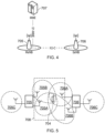
- FIG 4 shows a schematic representation of an example control plane architecture for dual connectivity.
- a master network access node 705 designated MeNB
- a secondary network access node 706 designated SeNB
- X2-C layer protocol In dual connectivity only the MeNB 705 is designated for RRC handling. Consequently, the RRC entity resides in the MeNB 705, and communication with the core network in the form of a mobility management entity 707 (MME) via an S1-MME protocol layer terminates in the MeNB 705.
- MME mobility management entity 707
- MeNB Mobility Node B
- SeNB SeNode B
- FIG. 5 shows a schematic representation of part of a network having a MeNB 705 supporting three cells 705A, 705B and 705C, and a SeNB 706 supporting three cells 706A, 706B and 706C.
- a user equipment UE 704 has access to cells from both eNBs, indicated as the group 708. Within the group 708, one cell can be a primary cell, from the MeNB cells.
- the MeNB cells 705A and 705B are designated as a master cell group MCG, and the SeNB cells 706A and 706B are designated as a secondary cell group SCG.
- the UE 704 has access to the two cells of MCG and the two cells of the SCG, indicated by the overlapping cell areas in Figure 5 .
- a purpose of the dual connectivity arrangement is to enable sharing and combining of resources belonging to different network access nodes. This sharing is expressed in the concept of split bearers.
- Figure 6A show a schematic representation of an example user plane protocol stack for a dual connectivity arrangement.
- an incoming message arrives via a bearer and is handled by the various protocol layers defined within the network architecture.
- MCG bearer 709 a bearer intended for the MeNB 705 as a master cell group bearer
- SCG bearer 710 a bearer intended for the SeNB 706 as a secondary cell group bearer
- a bearer arrives via the S1 protocol layer, is handled by the eNB's resources in turn by a packet data convergence protocol (PDCP), then a radio link control (RLC) protocol, and then the medium access control (MAC) layer.
- PDCP packet data convergence protocol
- RLC radio link control
- MAC medium access control
- each eNB 705, 706 has these resource layers to handle received bearers.
- a split bearer 711 is delivered to a PDCP in the MeNB 705, and the MeNB 705, at the PDCP, then controls a split or division of the split bearer's data between the MeNB 705 and the SeNB 706.
- Data for the MeNB 705 is passed to the MeNB's RLC and then its MAC
- data for the SeNB 706 is passed from the MeNB 705, using the X2 protocol layer, to an RLC in the SeNB and then to the MAC of the SeNB.
- a UE In order to be able to handle a message carried by a split bearer once it is passed on from the two eNBs, a UE is provided with two MAC entities, a master cell group MAC (MCG MAC) and a secondary cell group MAC (SCG MAC), plus corresponding RLC and PDCP. These are included in the resources of the UE for split bearer handling.
- MCG MAC master cell group MAC
- SCG MAC secondary cell group MAC
- the MeNB has a RRC entity, so signalling radio bearers for RRC are transported over the MCG only, i.e. by MCG bearer.
- MCG bearer For UEs configured for dual connectivity and split bearer transport, user traffic from the core network can be received at the MeNB as a split bearer, and then divided between the MeNB and the SeNB for handling and passing to the UE. Any traffic on a SCG bearer is received from the core network at the SeNB and transported using resources of the SeNB to the UE.
- a bearer arrives at the PDCP protocol layer.
- the PDCP is involved in security of the data traffic, including ciphering using a key.
- Each PDCP in each network entity eNBs and UEs, for example
- the MeNB may use a key designated as KeNB
- the SeNB may use a key designated as SKeNB.
- Other parameters are utilised by the PDCP together with the key to effect security; these include a numerical counter to generate successive numbers in a sequence of count values. Hence there is a set of parameters, used in a security algorithm to perform the ciphering.
- Each set of parameters, one for each successive number from the count value, is used only once for ciphering, to maintain security.
- the count value has a maximum number that can be generated, so for a given key, once this number is reached, there are no new parameter sets available for ciphering. Re-use of parameters is undesirable, so it is preferred to acquire a new key for the PDCP and start the count value sequence again at its beginning (at zero, for example), to work through all successive values in the count value sequence with the new key.
- the expiration of the numbers available from the counter can be referred to as "rollover”, and hereinafter the disclosure may mention “PDCP rollover”, “PDCP counter rollover”, "PDCP count rollover or "count rollover”.
- the process following rollover including acquisition of a new key, has a high processing overhead associated with it, and requires a resetting of the MAC layer for handling of ciphering with the new key.
- An example of a possible network configuration for future telecommunications is an arrangement comprising an LTE architecture providing wide (macro) coverage in conjunction with a so-called new radio (NR), referring to current and future telecommunications methods allowing increased data throughput, such as 4th and 5th generations (4G and 5G) and further.
- the type of radio access technology (RAT) used in the LTE network and the new radio network may be different, but an LTE network and a NR network could interwork, where a benefit of having connectivity to both LTE and NR is reduced signalling towards the core network from mobility towards the core network being anchored at the LTE macro entity, combined with higher throughput made possible be utilising resources in both LTE and NR.
- a terminal device will be configured to operate under both RATs.
- dual connectivity may be relevant, such that MeNBs may be designated from LTE and SeNBs from NR, or vice versa.
- Split bearers may also therefore be relevant for networks that support interworking between network access nodes based on different generations of radio access technology, for example a network that supports tight interworking between an LTE-based network access node and a NR-based network access node, and to facilitate this, a new split bearer configuration has been proposed, namely a secondary cell group split bearer, or SCG split bearer.
- FIG 6B shows a schematic representation of an example user plane protocol stack utilising a SCG split bearer.
- a master node 705 in this example in the LTE side
- a secondary node 706 each receive their designated bearers, MCG bearer 709 and SCG bearer 710 respectively, and these are handled by a PCDP, a RLC and a MAC layer, as before.
- No split bearer of the type shown in Figure 6A is included, however.
- SCG split bearer 712 which is delivered to the SeNB 706 (labelled Secondary gNB in Figure 5 to indicate a difference from the eNB of Figure 4 owing to the addition of the NR network).
- a PDCP in the SeNB 706 receives the SCG split bearer 712 and divides the data. Some is retained in the SeNB, being passed to the RLC and MAC layers. Other data is passed from the SeNB 706 to the MeNB 705 via an X protocol layer (labelled Xnew to indicate possible change from the X layers within LTE, such as the X1 layer in Figure 6A ), and the MeNB 705 handles it with its own RLC and MAC resources.
- X protocol layer labelled Xnew to indicate possible change from the X layers within LTE, such as the X1 layer in Figure 6A
- dual connectivity may be used to support a terminal device during handover. Furthermore, it has been recognised this may involve a secondary network access node switching roles to become a master network access node, see, for example, "SgNB to MgNB reconfiguration for 0ms interruption handover", 3GPP TSG-RAN WG2 #97bis, R2-1703381, submitted for meeting at Spokane, USA, 3-7 April, 2017.
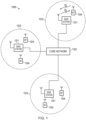
- FIG 7 schematically sets out a scenario in which dual connectivity may be used to support terminal device handover.
- a terminal device follows a path (UE path) that passes through the coverage areas of three communication cells (cell #1, cell #2 and cell #3) respectively supported by three network access nodes (NAN #1, NAN #2, NAN #3), as schematically represented in Figure 7 .
- Dual connectivity may be used to support continuous communications with the terminal device as it moves along this path.
- the terminal device is in communication cell #1.
- the terminal device may be configured for single connectivity on cell #1 (i.e. the terminal device is connected to NAN #1).
- communications associated with the terminal device may be made via NAN #1.
- the terminal device is entering an overlap region between cell #1 and cell #2. This may be determined in accordance with conventional techniques associated with mobility in wireless telecommunications systems, for example taking account of relative radio channel conditions associated with NAN #1 and NAN #2.
- the terminal device is configured for dual connectivity with NAN #2 being configured for use as a secondary network access node (SeNB).
- SeNB secondary network access node
- communications associated with the terminal device may be made via NAN #1 and / or NAN #2, in accordance with established proposals for dual connectivity.
- the terminal device has moved out of coverage of NAN #1.
- the terminal device may remain configured for dual connectivity with NAN #1 acting as master network access node (MeNB), despite being out of radio coverage, and NAN #2 acting as secondary network access node (MeNB). At this point communications with the terminal device may pass through NAN #2.
- NAN #1 acting as master network access node (MeNB)
- MeNB master network access node
- MeNB secondary network access node
- the terminal device is entering an overlap region between cell #2 and cell #3. This may be determined in accordance with conventional techniques associated with mobility in wireless telecommunications systems, for example taking account of relative radio channel conditions associated with NAN #2 and NAN #3.
- the terminal device's dual connectivity configuration is changed with NAN #3 being configured for use as a secondary network access node (SeNB), and NAN #2 consequently being reconfigured from being a secondary network access node to being a master network access node (MeMB).
- communications associated with the terminal device may be made via NAN #2 and / or NAN #3, in accordance with established proposals for dual connectivity.
- the terminal device has moved out of coverage of NAN #2.
- the terminal device may remain configured for dual connectivity with NAN #2 acting as master network access node (MeNB), despite being out of radio coverage, and NAN #3 acting as secondary network access node (MeNB). At this point communications with the terminal device may pass through NAN #3.
- MeNB master network access node
- MeNB secondary network access node
- the terminal device may retain its existing dual connectivity configuration as it moves out of an overlap region between two cells towards the centre of one of the cells (e.g. moving from point "W” to point "X", or moving from point "Y” point “Z”).
- this may result in a situation in which a terminal device is not within radio coverage of its master network access node, so that all communications are routed only through the secondary network access node. This may be considered undesirable in some cases.
- a secondary network access node may switch roles to become a master network access node sooner.
- NAN #2 switches from being a secondary network access node to being a master network access node for the terminal device when the terminal device is around point "Y" on its path.
- NAN #2 may instead switch from being a secondary network access node to being a master network access node (or indeed a sole network access node without using dual connectivity) for the terminal device when the terminal device is around point "P" on its path.
- Security key handling is an important aspect of wireless telecommunications systems.
- An example overview of security key generation in this example in the context of an LTE system, is schematically shown in Figure 8 . Further details of the established practices for security key generation, such as represented in Figure 8 , are well understood and use can also be found in the relevant standards, for example ETSI TS 136 300 V13.2.0 (2016-01) / 3GPP TS 36.300 version 13.2.0 Release 13 [7] (in particular Section 14).
- Figure 8 corresponds to Figure 14.1-1 in ETSI TS 136 300 V13.2.0 (2016-01) / 3GPP TS 36.300 version 13.2.0 Release 13 [7] and schematically represents keys derived at different entities when an AKA (Authentication and Key Agreement) procedure is run. Signalling for the AKA procedure is not represented here for simplicity, but details of this can found, for example, in ETSI TS 33 401 V14.2.0 (2016-01) / 3GPP TS 33.401 version 14.2.0 Release 14 [8] (e.g. see Section 7).
- the bottom set of keys represented in Figure 8 are used for user plane encryption (KUP enc), RRC encryption (RRC enc ) and RRC integrity protection (KRRC int) (user plane data is not integrity protected).
- KeNB* is a key associated with handover. It is derived by a terminal device and source network access node from either KeNB or from a fresh new hop (NH). KeNB* is used by the terminal device and target network access node as a new KeNB for RRC (radio resource control) and UP (user plane) traffic.
- RRC radio resource control
- UP user plane
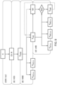
- Figure 9 corresponds to Figure 7.2.8.1-1 in ETSI TS 33 401 V14.2.0 (2016-01) / 3GPP TS 33.401 version 14.2.0 Release 14 [8] and schematically represents key handling during handover.
- the generation of KeNB* has EARFCN-DL (E-UTRA Absolute Radio Frequency Channel Number - downlink) and PCI (Physical Cell Identity) as inputs (and existing KeNB).
- EARFCN-DL E-UTRA Absolute Radio Frequency Channel Number - downlink
- PCI Physical Cell Identity
- PCI Physical Cell Identity
- the master network access node may use a key designated KeNB and the secondary network access node may use a key designated SKeNB.
- Figure 10 schematically represents an approach for SKeNB generation.
- the SKeNB is generated by the master network access node and terminal device using a key derivation function having the KeNB and a secondary cell group counter as inputs (it does not use a cell ID / PCI as an input).
- the SKeNB is passed from the master network access node to the secondary network access node when adding a secondary cell group.
- the SKeNB is then used by the secondary network access node and terminal device to generate KUPenc (key for user plane encryption) for the secondary network access node.
- Figure 10 corresponds to Figure 14.1-2 in ETSI TS 136 300 V13.2.0 (2016-01) / 3GPP TS 36.300 version 13.2.0 Release 13 [7] and further details of the process can be found therein.
- Figure 11 is a signalling ladder diagram schematically representing some operating aspects of the wireless telecommunications system 200 shown in Figure 5 in accordance with certain embodiments of the disclosure.
- the diagram represents some operations and signalling exchange associated with the terminal device 208, the source network access node 204, the target network access node 206 and the core network 202 in accordance with certain embodiments of the disclosure.
- the terminal device is initially operating on the source network access node (which may also be referred to as a first network access node). The terminal device then moves towards a boundary region between the source network access node and the target network access node (which may also be referred to as a second network access node). In response the terminal device is configured for dual connectivity with the source network access node acting as a master network access node (MeNB) and the target network access node acting as a secondary network access node (SeNB).
- MeNB master network access node
- SeNB secondary network access node
- the terminal device moves away from the coverage of the source network access node (configured as the master network access node for the dual connectivity), and consequently the second network access node (configured as the secondary network access node for the dual connectivity) is reconfigured as a master network access node for dual connectivity.
- processing starts in S1 with the terminal device 208 being connected to the source (first) network access node 204.
- step S2 of the processing it is determined the terminal device should enter a dual connectivity mode of operation because it is approaching a boundary region between the source and target network access nodes (i.e. there is a potential for handover from the source network access node to the target network access node).
- the manner in which it is determined the terminal device is entering a boundary region and a handover procedures should be initiated may be based on conventional techniques. For example taking account of measurements of radio channel conditions between the terminal device and respective ones of the network access nodes, such as a received power or quality of reference symbols transmitted by the respective network access nodes. It will be appreciated that different ways of measuring radio channel conditions may be provided in different implementations.
- radio channel conditions measurements may be based on uplink reference signalling, rather than downlink reference signalling.
- uplink reference signalling rather than downlink reference signalling.
- the source network access node is configured as a master network access node for the dual connectivity and is associated with a master network access node security key (e.g. a KeNB) and the target network access node is configured as a secondary network access node for the dual connectivity and is associated with a secondary network access node security key (e.g. a SKeNB).
- a master network access node security key e.g. a KeNB
- a secondary network access node security key e.g. a SKeNB
- the derivation and sharing of the master network access node security key and the secondary network access node security key may be based on conventional techniques.
- the source network access node may derive the secondary network access node security key from the master network access node security key in accordance with established practices, for example using a key derivation function of the kind represented in Figure 10 , and may convey an indication of the secondary network access node security key to the target network access node and the terminal device.
- the secondary network access node security key itself may not be sent from the source network access node 204 to the target network access node 206 and / or the terminal device 208, but rather an indication that allows the target network access node and the terminal device to independently derive the secondary network access mode security key may be sent instead.
- the secondary network access node security key itself it will typically be encrypted. Nonetheless, for terminological convenience, the process of conveying information to allow a security key to be derived may be referred to herein as simply sending the security key.
- step S6 it is determined the current dual connectivity role of the target network access node (i.e. the network access node currently acting as a secondary network access node for the dual connectivity with the terminal device) should be switched, and in particular the source network access node for the handover should be configured as a new master network access for supporting dual connectivity with the terminal device.
- the target network access node i.e. the network access node currently acting as a secondary network access node for the dual connectivity with the terminal device
- the source network access node for the handover should be configured as a new master network access for supporting dual connectivity with the terminal device. This may be based on determining the mobile terminal device is moving away from the coverage of the first network access node (currently acting as master network access node) and towards the coverage of a further network access node, example as discussed above with reference to Figure 7 . This determination may again be based on measurements of radio channel conditions associated with the various network access nodes.
- the decision may be made by either one of the source and target network access nodes according to the implementation at hand. It will be appreciated the specific manner in which it is determined when the secondary network access node should be reconfigured as a master network access node is not of primary significance to the principles described herein.
- the target network access node i.e. the network access node which is to switch from acting as a secondary network access node to a master network access node
- KeNB new master network access node security
- the new master network access node security key may be derived by the target network access node, as discussed further below.
- the target network access node conveys an indication of the new master network access node security key to the terminal device and the core network, thereby allowing the target network access node to switch from operating as a secondary network access node to a master network access node for the terminal device.
- the new master network access node security key itself may not be sent from the source network access node 204 to the target network access node 206 and / or the terminal device 208, but rather an indication that allows the target network access node and the terminal device to independently derive the new master network access mode security key may be sent instead.
- any security keys are sent between elements of the wireless telecommunications system, they may be encrypted. Nonetheless, and as already mentioned above, for terminological convenience and ease of representation in the figures, the process of conveying information to allow a security key to be derived may be referred to herein and schematically shown in the figures as simply sending the security key.
- processing discussed above in relation to Figure 11 represents an approach for handling security keys to support the use of dual connectivity for handover in wireless telecommunication systems in accordance with certain embodiments of the disclosure.
- Figure 11 schematically represents a method of operation in a wireless telecommunication system comprising a terminal device, a first network access node and a second network access node.
- the example method includes configuring the second network access node to act as a secondary network access node for a dual connectivity mode of operation for the terminal device in which the first network access node acts as a master network access node, wherein the first network access node is associated with a master network access node security key and the second network access node is associated with a secondary network access node security key, wherein the secondary network access node security key is derived from the master network access node security key and is established by the second network access node from information received from the first network access node.
- the example method further includes establishing, while the second network access node is acting as secondary network access node for the dual connectivity mode of operation for the terminal device, that the second network access node should switch to acting as a master network access node for the dual connectivity mode of operation for the terminal device.
- the example method further includes the second network access node deriving a new master network access node security key to be used by the second network access node when it is switched to acting as a master network access node for the dual connectivity mode of operation for the terminal device.
- the example method further includes configuring the second network access node to act a master network access node for the dual connectivity mode of operation for the terminal device using the new master network access node security key, example this may involve riding the core network and the terminal device with an indication of the new master network access node key and that the changing role has occurred.
- the new master network access node key may be derived by the second network access node in step S7.
- the new master network access node security key may be derived by the second network access node from the secondary network access node security key.
- the new master network access node security key a be derived from the secondary network access nodes existing secondary network access node security key using a key derivation process defined for use in the wireless telecommunications system for generating a target network access node security key from a source network access node security key in a handover procedure, example using an approach such as that represented in Figure 9 .
- the new master network access node security key may be derived by combining the existing secondary network access node security key with a predetermined number, example in logical AND, OR or XOR type of operation.
- the predetermined number may be fixed, or correspond with a counter associated with the terminal device.
- the new master network access node security may simply be taken to be the same as the existing secondary network access node security key (i.e. the existing secondary network access node security may be used as a master network access node security key).
- the new master network access node security key might not be derived from the existing secondary network access node security key, but may instead be reconfigured by triggering an authentication and key agreement, AKA, procedure to refresh security keys associated with the terminal device in the wireless telecommunications system.
- AKA authentication and key agreement
- This procedure may be based on conventional techniques, or maybe a shortened / reduced procedure in which not all keys are refreshed.
- the wireless network may support a hierarchical arrangement of security keys of the kind represented in Figure 8 , whereby a security key at one level in the hierarchy is used to derive a security key at the next level down in the hierarchy.
- a reduced authentication and key agreement procedure may be run to refresh a key in the hierarchical level above the network access node security keys (e.g. to refresh the key KASME in the example of Figure 8 ), but without refreshing higher layer keys.
- This kind of reduced / shortened AKA procedure may be run more quickly than a full AKA procedure.
- the new master network access node key may be derived by the second network access node based on information received from the first network access node.
- the new master network access node key may be provided to the secondary network access nodes by the master network access node in a corresponding manner to that in which a KeNB* key is provided to a target network access node by a source network access node in a conventional handover procedure.
- the second network access node may be associated with a secondary network access node security key as part of being configured as a secondary network access node even in cases where the secondary network access node is not configured for use with a secondary cell group dual connectivity mode of operation. Normally in such cases the secondary network access node in a dual connectivity scenario would not have its own security context, and so would not be associated with a security key. Nonetheless, in accordance with certain embodiments of the disclosure, a network access node may be associated with network access node security key win configured as a secondary network access node for dual connectivity, even if it does not need the key to support that dual connectivity. This is so that the secondary network access node has the key nonetheless so that it may be used later used to generate a new master network access node security key if the secondary network access node needs to switch roles in this regard.
- steps S4 and S5 may be performed later in the process, for example only after step S6 when it is determined a change in role should occur (the secondary network access node does not need the SKeNB to support all forms of dual connectivity).
- steps S5 and S9 can be combined (i.e. the terminal device can be provided with an indication of SKeNB and KeNB at the same time), and likewise steps S4 and S8 may be combined in some cases.
- the two-stage approach represented in Figure 11 may be considered preferable in some circumstances because it can help reduce interruptions in data transfer.
- steps S5 and S9 are combined in a single step, this combined step may be performed at a point corresponding to step S5 or S9 in the processing represented in Figure 11 .
- step S7 will also need to be performed before S5.
- a KeNB may be established by the secondary network access node and shared with the terminal device and core network before it is determined the role change should occur. This can help make the role change faster when it is triggered as some of the security key handling has already been performed.
- the terminal device When the terminal device has a KeNB associated with the master network access node, and also a new KeNB associated with the secondary network access node, it may include an indication in association with its uplink transmissions, e.g. a setting in a field in a packet header, to indicate which security has been used.
- an indication in association with its uplink transmissions e.g. a setting in a field in a packet header, to indicate which security has been used.
- the core network e.g. when steps S4 and S8 are combined in a single step, the combined step may be performed at a point corresponding to step S4 or S8 in the processing represented in Figure 11 .
- the method comprises: configuring the second network access node to act as a secondary network access node for a dual connectivity mode of operation for the terminal device in which the first network access node acts as a master network access node, wherein the first network access node is associated with a master network access node security key and the second network access node is associated with a secondary network access node security key, wherein the secondary network access node security key is derived from the master network access node security key and is established by the second network access node from information received from the first network access node; establishing, while the second network access node is acting as secondary network access node for the dual connectivity mode of operation for the terminal device, that the second network access node should switch to acting as a master network access node for the dual connectivity mode of operation for the terminal device; deriving a new master network access node security
- predetermined / predefined information may in general be established, for example, by definition in an operating standard for the wireless telecommunication system, or in previously exchanged signalling between the base station and terminal devices, for example in system information signalling, or in association with radio resource control setup signalling. That is to say, the specific manner in which the relevant predefined information is established and shared between the various elements of the wireless telecommunications system is not significance to the principles of operation described herein.
- Paragraph 2 The method of paragraph 1, wherein the new master network access node security key is derived by the second network access node from the secondary network access node security key.
- Paragraph 3 The method of paragraph 2, wherein the new master network access node security key is derived from the secondary network access node security key using a key derivation process used in the wireless telecommunications system for generating a target network access node security key from a source network access node security key in a handover procedure.
- Paragraph 4 The method of paragraph 2, wherein the new master network access node security key is derived from the secondary network access node security key by combining the secondary network access node security key with a predetermined number.
- Paragraph 5 The method of paragraph 4, wherein predetermined number is a fixed number or a number derived from a counter.
- Paragraph 6 The method of paragraph 2, wherein the new master network access node security key is the same as the secondary network access node security key.
- Paragraph 7 The method of any of paragraphs 1 to 6, further comprising the second network access node conveying to the terminal device an indication of the new master network access node security key.
- Paragraph 8 The method of any of paragraphs 1 to 7, further comprising the second network access node conveying to a core network part of the wireless telecommunications system an indication of the new master network access node security key.
- Paragraph 9 The method of any of paragraphs 1 to 8, wherein the new master network access node security key is derived by running an authentication and key agreement, AKA, procedure to refresh security keys associated with the terminal device in the wireless telecommunications system.
- AKA authentication and key agreement
- Paragraph 10 The method of paragraph 9, wherein the wireless network supports a hierarchical arrangement of security keys, whereby a security key at one level in the hierarchy is used to derive a security key at the next level down in the hierarchy, and wherein the new master network access node security key is at a first level in the hierarchy and the authentication and key agreement, AKA, procedure is a reduced authentication and key agreement, AKA, procedure for refreshing keys in a level in the hierarchy that is one level above the first level, but not at a higher levels in the hierarchy.
- Paragraph 11 The method of any of paragraphs 1 to 10, wherein the new master network access node security key is derived by the second network access node using information received from the first network access node.
- Paragraph 12 The method of any of paragraphs 1 to 11, wherein the second network access node is not configured for use with a secondary cell group bearer when it is configured to act as a secondary network access node.
- Paragraph 13 The method of any of paragraphs 1 to 12, wherein the step of establishing that the second network access node should switch to acting as a master network access node for the dual connectivity mode of operation for the terminal device is based on a measurement of radio channel conditions between the terminal device and the first and / or second network access node.
- Paragraph 14 The method of any of paragraphs 1 to 13, further comprising receiving, from the terminal device, a block of data, and establishing from an indication received from the terminal device in association with the block of data an identifier for a security key used by the terminal device for its transmission of the block of data.
- a second network access node for use in a wireless telecommunication system comprising a terminal device, a first network access node and the second network access node, wherein the second network access node comprises controller circuitry and transceiver circuitry configured to operate together such that the second network access node is operable to: configure the second network access node to act as a secondary network access node for a dual connectivity mode of operation for the terminal device in which the first network access node acts as a master network access node, wherein the first network access node is associated with a master network access node security key and the second network access node is associated with a secondary network access node security key, wherein the secondary network access node security key is derived from the master network access node security key and is established by the second network access node from information received from the first network access node; establish, while the second network access node is acting as secondary network access node for the dual connectivity mode of operation for the terminal device, that the second network access node should switch to acting as a master network access node
- Circuitry for a second network access node for use in a wireless telecommunication system comprising a terminal device, a first network access node and the second network access node, wherein the circuitry comprises controller circuitry and transceiver circuitry configured to operate together such that the circuitry is operable to: configure the second network access node to act as a secondary network access node for a dual connectivity mode of operation for the terminal device in which the first network access node acts as a master network access node, wherein the first network access node is associated with a master network access node security key and the second network access node is associated with a secondary network access node security key, wherein the secondary network access node security key is derived from the master network access node security key and is established by the second network access node from information received from the first network access node; establish, while the second network access node is acting as secondary network access node for the dual connectivity mode of operation for the terminal device, that the second network access node should switch to acting as a master network access node for the
- a method of operating a terminal device in a wireless telecommunication system comprising the terminal device, a first network access node and a second network access node, wherein the method comprises: configuring the terminal device to operate in a dual connectivity mode of operation with the first network access node acting as a master network access node for the dual connectivity mode of operation and the second network access node acting as a secondary network access node, wherein the first network access node is associated with a master network access node security key and the second network access node is associated with a secondary network access node security key, wherein the secondary network access node security key is derived from the master network access node security key; establishing, while the second network access node is acting as secondary network access node for the dual connectivity mode of operation for the terminal device, that the second network access node is to switch to acting as a master network access node for the dual connectivity mode of operation for the terminal device; establishing a new master network access node security key to be used by the second network access node when it is switched to acting
- a terminal device for use in a wireless telecommunication system comprising the terminal device, a first network access node and a second network access node, wherein the terminal device comprises controller circuitry and transceiver circuitry configured to operate together such that the terminal device is operable to: configure the terminal device to operate in a dual connectivity mode of operation with the first network access node acting as a master network access node for the dual connectivity mode of operation and the second network access node acting as a secondary network access node, wherein the first network access node is associated with a master network access node security key and the second network access node is associated with a secondary network access node security key, wherein the secondary network access node security key is derived from the master network access node security key; establish, while the second network access node is acting as secondary network access node for the dual connectivity mode of operation for the terminal device, that the second network access node is to switch to acting as a master network access node for the dual connectivity mode of operation for the terminal device; establish a new master network access node
- Circuitry for a terminal device for use in a wireless telecommunication system comprising the terminal device, a first network access node and a second network access node, wherein the circuitry comprises controller circuitry and transceiver circuitry configured to operate together such that the circuitry is operable to: configure the terminal device to operate in a dual connectivity mode of operation with the first network access node acting as a master network access node for the dual connectivity mode of operation and the second network access node acting as a secondary network access node, wherein the first network access node is associated with a master network access node security key and the second network access node is associated with a secondary network access node security key, wherein the secondary network access node security key is derived from the master network access node security key; establish, while the second network access node is acting as secondary network access node for the dual connectivity mode of operation for the terminal device, that the second network access node is to switch to acting as a master network access node for the dual connectivity mode of operation for the terminal device; establish a new master master network
Landscapes
- Engineering & Computer Science (AREA)
- Computer Networks & Wireless Communication (AREA)
- Signal Processing (AREA)
- Computer Security & Cryptography (AREA)
- Computer Hardware Design (AREA)
- Computing Systems (AREA)
- General Engineering & Computer Science (AREA)
- Mobile Radio Communication Systems (AREA)
Claims (11)
- Verfahren zum Betreiben eines zweiten Netzwerkzugangsknotens (206) in einem drahtlosen Telekommunikationssystem, das ein Endgerät (208), einen ersten Netzwerkzugangsknoten (204) und den zweiten Netzwerkzugangsknoten umfasst, wobei das Verfahren Folgendes umfasst:derartiges Konfigurieren des zweiten Netzwerkzugangsknotens, dass er als sekundärer Netzwerkzugangsknoten für einen Doppelkonnektivitäts-Betriebsmodus für das Endgerät fungiert, in dem der erste Netzwerkzugangsknoten als Master-Netzwerkzugangsknoten fungiert, wobei der erste Netzwerkzugangsknoten mit einem Master-Netzwerkzugangsknoten-Sicherheitsschlüsselassoziiert ist und der zweite Netzwerkzugangsknoten mit einem Sekundärnetzwerkzugangsknoten-Sicherheitsschlüssel assoziiert ist, wobei der Sekundärnetzwerkzugangsknoten-Sicherheitsschlüssel von dem Master-Netzwerkzugangsknoten-Sicherheitsschlüssel abgeleitet ist und durch den zweiten Netzwerkzugangsknoten aus von dem ersten Netzwerkzugangsknoten empfangenen Informationen erstellt wird;Festlegen (S6), während der zweite Netzwerkzugangsknoten als sekundärer Netzwerkzugangsknoten für den Doppelkonnektivitäts-Betriebsmodus für das Endgerät fungiert, dass der zweite Netzwerkzugangsknoten zum Fungieren als Master-Netzwerkzugangsknoten für das Endgerät wechseln sollte;Ableiten (S7) eines neuen Master-Netzwerkzugangsknoten-Sicherheitsschlüssels, der durch den zweiten Netzwerkzugangsknoten zu verwenden ist, wenn er zum Fungieren als Master-Netzwerkzugangsknoten für das Endgerät wechselt; undderartiges Konfigurieren des zweiten Netzwerkzugangsknotens, dass er als Master-Netzwerkzugangsknoten für das Endgerät fungiert, unter Verwendung des neuen Master-Netzwerkzugangsknoten-Sicherheitsschlüssels,gekennzeichnet durchwobei der neue Master-Netzwerkzugangsknoten-Sicherheitsschlüssel von dem Sekundärnetzwerkzugangsknoten-Sicherheitsschlüsseldurch Kombinieren des Sekundärnetzwerkzugangsknoten-Sicherheitsschlüssels mit einer vorbestimmten Zahl abgeleitet wird.
- Verfahren nach Anspruch 1, ferner umfassend, dass der zweite Netzwerkzugangsknoten eine Angabe des neuen Master-Netzwerkzugangsknoten-Sicherheitsschlüssels an das Endgerät übermittelt.
- Verfahren nach Anspruch 1, ferner umfassend, dass der zweite Netzwerkzugangsknoten eine Angabe des neuen Master-Netzwerkzugangsknoten-Sicherheitsschlüssels an einen Kernnetzwerkteil des drahtlosen Telekommunikationssystems übermittelt.
- Verfahren nach Anspruch 1, wobei der zweite Netzwerkzugangsknoten nicht zur Verwendung mit einem sekundären Zellengruppenträger konfiguriert ist, wenn er zum Fungieren als sekundärer Netzwerkzugangsknoten konfiguriert ist.
- Verfahren nach Anspruch 1, wobei der Schritt des Festlegens, dass der zweite Netzwerkzugangsknoten zum Fungieren als Master-Netzwerkzugangsknoten für das Endgerät wechseln sollte, auf einer Messung von Funkkanalbedingungen zwischen dem Endgerät und dem ersten und/oder zweiten Netzwerkzugangsknoten basiert.
- Verfahren nach Anspruch 1, ferner umfassend Empfangen, von dem Endgerät, eines Datenblocks und Erstellen, aus einer von dem Endgerät in Verbindung mit dem Datenblock empfangenen Angabe, einer Kennung für einen Sicherheitsschlüssel, der durch das Endgerät für seine Übertragung des Datenblocks verwendet wird.
- Schaltungsanordnung für einen zweiten Netzwerkzugangsknoten (206) zur Verwendung in einem drahtlosen Telekommunikationssystem, das ein Endgerät (208), einen ersten Netzwerkzugangsknoten (204) und den zweiten Netzwerkzugangsknoten umfasst, wobei die Schaltungsanordnung eine Steuerungsschaltungsanordnung und eine Transceiverschaltungsanordnung umfasst, die dazu ausgelegt sind, so zusammen zu arbeiten, dass die Schaltungsanordnung zu Folgendem betreibbar ist:derartiges Konfigurieren des zweiten Netzwerkzugangsknotens, dass er als sekundärer Netzwerkzugangsknoten für einen Doppelkonnektivitäts-Betriebsmodus für das Endgerät fungiert, in dem der erste Netzwerkzugangsknoten als Master-Netzwerkzugangsknoten fungiert, wobei der erste Netzwerkzugangsknoten mit einem Master-Netzwerkzugangsknoten-Sicherheitsschlüsselassoziiert ist und der zweite Netzwerkzugangsknoten mit einem Sekundärnetzwerkzugangsknoten-Sicherheitsschlüssel assoziiert ist, wobei der Sekundärnetzwerkzugangsknoten-Sicherheitsschlüssel von dem Master-Netzwerkzugangsknoten-Sicherheitsschlüssel abgeleitet ist und durch den zweiten Netzwerkzugangsknoten aus von dem ersten Netzwerkzugangsknoten empfangenen Informationen erstellt wird;Festlegen (S6), während der zweite Netzwerkzugangsknoten als sekundärer Netzwerkzugangsknoten für den Doppelkonnektivitäts-Betriebsmodus für das Endgerät fungiert, dass der zweite Netzwerkzugangsknoten zum Fungieren als Master-Netzwerkzugangsknoten für das Endgerät wechseln sollte;Ableiten (S7) eines neuen Master-Netzwerkzugangsknoten-Sicherheitsschlüssels, der durch den zweiten Netzwerkzugangsknoten zu verwenden ist, wenn er zum Fungieren als Master-Netzwerkzugangsknoten für das Endgerät wechselt; undderartiges Konfigurieren des zweiten Netzwerkzugangsknotens, dass er als Master-Netzwerkzugangsknoten für das Endgerät fungiert, unter Verwendung des neuen Master-Netzwerkzugangsknoten-Sicherheitsschlüssels,gekennzeichnet durchwobei der neue Master-Netzwerkzugangsknoten-Sicherheitsschlüssel von dem Sekundärnetzwerkzugangsknoten-Sicherheitsschlüssel durch Kombinieren des Sekundärnetzwerkzugangsknoten-Sicherheitsschlüssels mit einer vorbestimmten Zahl abgeleitet wird.
- Zweiter Netzwerkzugangsknoten (206) zur Verwendung in einem drahtlosen Telekommunikationssystem, das ein Endgerät (208), einen ersten Netzwerkzugangsknoten (204) und den zweiten Netzwerkzugangsknoten umfasst,
wobei der zweite Netzwerkzugangsknoten die Schaltungsanordnung nach Anspruch 7 umfasst. - Verfahren zum Betreiben eines Endgeräts (208) in einem drahtlosen Telekommunikationssystem, das das Endgerät, einen ersten Netzwerkzugangsknoten (204) und einen zweiten Netzwerkzugangsknoten (206) umfasst, wobei das Verfahren Folgendes umfasst:derartiges Konfigurieren des Endgeräts, dass es in einem Doppelkonnektivitäts-Betriebsmodus arbeitet, wobei der erste Netzwerkzugangsknoten als Master-Netzwerkzugangsknoten für den Doppelkonnektivitäts-Betriebsmodus fungiert und der zweite Netzwerkzugangsknoten als sekundärer Netzwerkzugangsknoten fungiert, wobei der erste Netzwerkzugangsknoten mit einem Master-Netzwerkzugangsknoten-Sicherheitsschlüssel assoziiert ist und der zweite Netzwerkzugangsknoten mit einem Sekundärnetzwerkzugangsknoten-Sicherheitsschlüsselassoziiert ist, wobei der Sekundärnetzwerkzugangsknoten-Sicherheitsschlüssel von dem Master-Netzwerkzugangsknoten-Sicherheitsschlüssel abgeleitet ist;Festlegen, während der zweite Netzwerkzugangsknoten als sekundärer Netzwerkzugangsknoten für den Doppelkonnektivitäts-Betriebsmodus für das Endgerät fungiert, dass der zweite Netzwerkzugangsknoten zum Fungieren als Master-Netzwerkzugangsknoten für das Endgerät wechseln soll;Erstellen eines neuen Master-Netzwerkzugangsknoten-Sicherheitsschlüssels, der durch den zweiten Netzwerkzugangsknoten zu verwenden ist, wenn er zum Fungieren als Master-Netzwerkzugangsknoten für das Endgerät wechselt; undderartiges Konfigurieren des zweiten Netzwerkzugangsknotens, dass er als Master-Netzwerkzugangsknoten für das Endgerät fungiert, unter Verwendung des neuen Master-Netzwerkzugangsknoten-Sicherheitsschlüssels,gekennzeichnet durchwobei der neue Master-Netzwerkzugangsknoten-Sicherheitsschlüssel von dem Sekundärnetzwerkzugangsknoten-Sicherheitsschlüsseldurch Kombinieren des Sekundärnetzwerkzugangsknoten-Sicherheitsschlüssels mit einer vorbestimmten Zahl abgeleitet wird.
- Schaltungsanordnung für ein Endgerät (208) zur Verwendung in einem drahtlosen Telekommunikationssystem, das das Endgerät, einen ersten Netzwerkzugangsknoten (204) und einen zweiten Netzwerkzugangsknoten (206) umfasst, wobei die Schaltungsanordnung eine Steuerungsschaltungsanordnung und eine Transceiverschaltungsanordnung umfasst, die dazu ausgelegt sind, so zusammen zu arbeiten, dass die Schaltungsanordnung zu Folgendem betreibbar ist:derartiges Konfigurieren des Endgeräts, dass es in einem Doppelkonnektivitäts-Betriebsmodus arbeitet, wobei der erste Netzwerkzugangsknoten als Master-Netzwerkzugangsknoten für den Doppelkonnektivitäts-Betriebsmodus fungiert und der zweite Netzwerkzugangsknoten als sekundärer Netzwerkzugangsknoten fungiert, wobei der erste Netzwerkzugangsknoten mit einem Master-Netzwerkzugangsknoten-Sicherheitsschlüssel assoziiert ist und der zweite Netzwerkzugangsknoten mit einem Sekundärnetzwerkzugangsknoten-Sicherheitsschlüsselassoziiert ist, wobei der Sekundärnetzwerkzugangsknoten-Sicherheitsschlüssel von dem Master-Netzwerkzugangsknoten-Sicherheitsschlüssel abgeleitet ist;Festlegen, während der zweite Netzwerkzugangsknoten als sekundärer Netzwerkzugangsknoten für den Doppelkonnektivitäts-Betriebsmodus für das Endgerät fungiert, dass der zweite Netzwerkzugangsknoten zum Fungieren als Master-Netzwerkzugangsknoten für das Endgerät wechseln soll;Erstellen eines neuen Master-Netzwerkzugangsknoten-Sicherheitsschlüssels, der von dem zweiten Netzwerkzugangsknoten zu verwenden ist, wenn er zum Fungieren als Master-Netzwerkzugangsknoten für das Endgerät wechselt; undderartiges Konfigurieren des zweiten Netzwerkzugangsknotens, dass er als Master-Netzwerkzugangsknoten für das Endgerät fungiert, unter Verwendung des neuen Master-Netzwerkzugangsknoten-Sicherheitsschlüssels,gekennzeichnet durchwobei der neue Master-Netzwerkzugangsknoten-Sicherheitsschlüssel von dem Sekundärnetzwerkzugangsknoten-Sicherheitsschlüsseldurch Kombinieren des Sekundärnetzwerkzugangsknoten-Sicherheitsschlüssels mit einer vorbestimmten Zahl abgeleitet wird.
- Endgerät (208) zur Verwendung in einem drahtlosen Telekommunikationssystem, das das Endgerät, einen ersten Netzwerkzugangsknoten (204) und einen zweiten Netzwerkzugangsknoten (206) umfasst,
wobei das Endgerät die Schaltungsanordnung nach Anspruch 10 umfasst.
Applications Claiming Priority (2)
| Application Number | Priority Date | Filing Date | Title |
|---|---|---|---|
| EP17163988 | 2017-03-30 | ||
| PCT/EP2018/057784 WO2018178081A1 (en) | 2017-03-30 | 2018-03-27 | Telecommunications apparatus and methods |
Publications (2)
| Publication Number | Publication Date |
|---|---|
| EP3603145A1 EP3603145A1 (de) | 2020-02-05 |
| EP3603145B1 true EP3603145B1 (de) | 2025-06-25 |
Family
ID=58489512
Family Applications (1)
| Application Number | Title | Priority Date | Filing Date |
|---|---|---|---|
| EP18712255.1A Active EP3603145B1 (de) | 2017-03-30 | 2018-03-27 | Telekommunikationsvorrichtung und -verfahren |
Country Status (4)
| Country | Link |
|---|---|
| US (2) | US11108755B2 (de) |
| EP (1) | EP3603145B1 (de) |
| CN (1) | CN110463240B (de) |
| WO (1) | WO2018178081A1 (de) |
Families Citing this family (14)
| Publication number | Priority date | Publication date | Assignee | Title |
|---|---|---|---|---|
| JP7093614B2 (ja) * | 2017-06-15 | 2022-06-30 | シャープ株式会社 | 端末装置、基地局装置、通信方法、および、集積回路 |
| US11252561B2 (en) * | 2017-06-26 | 2022-02-15 | Telefonaktiebolaget Lm Ericsson (Publ) | Refreshing a security context for a mobile device |
| WO2019141687A1 (en) | 2018-01-19 | 2019-07-25 | Sony Corporation | Method and apparatus for handoff of multiple bearers with differing quality of service levels in a wireless communication system |
| JP2020535667A (ja) * | 2018-08-28 | 2020-12-03 | アップル インコーポレイテッドApple Inc. | セルラ通信のための移動性向上 |
| EP3874822B1 (de) * | 2018-11-01 | 2025-08-06 | Apple Inc. | Bedingte übergaben und zellenneuauswahlen entlang bekannter routen |
| WO2021030576A1 (en) * | 2019-08-15 | 2021-02-18 | Google Llc | Security key updates in dual connectivity |
| WO2021066466A1 (en) * | 2019-10-02 | 2021-04-08 | Samsung Electronics Co., Ltd. | Method and apparatus for performing handover in wireless communication system |
| CN114521347B (zh) * | 2019-10-03 | 2025-09-16 | 夏普株式会社 | 条件主辅小区添加/修改配置的释放 |
| EP4102890A4 (de) * | 2020-03-26 | 2023-04-12 | Guangdong Oppo Mobile Telecommunications Corp., Ltd. | Zellenübergabeverfahren, elektronische vorrichtung und speichermedium |
| BR112022021032A2 (pt) * | 2020-04-21 | 2022-12-06 | Google Llc | Gerenciamento de uma configuração preferida do ue |
| CN115669070B (zh) * | 2020-07-30 | 2025-08-12 | Oppo广东移动通信有限公司 | 基于条件的辅节点或主辅小区变更方法及设备 |
| US11552943B2 (en) * | 2020-11-13 | 2023-01-10 | Cyberark Software Ltd. | Native remote access to target resources using secretless connections |
| US11552822B2 (en) * | 2021-03-24 | 2023-01-10 | Schweitzer Engineering Laboratories, Inc. | Systems and methods for establishing a backup secure communication link in an electric power distribution system |
| WO2023245038A1 (en) * | 2022-06-15 | 2023-12-21 | Convida Wireless, Llc | Managing role changes in personal iot networks |
Family Cites Families (10)
| Publication number | Priority date | Publication date | Assignee | Title |
|---|---|---|---|---|
| US10306596B2 (en) * | 2012-05-10 | 2019-05-28 | Samsung Electronics Co., Ltd | Method and system for connectionless transmission during uplink and downlink of data packets |
| DK2951975T3 (en) * | 2013-01-30 | 2016-10-24 | ERICSSON TELEFON AB L M (publ) | GENERATION OF SECURITY KEY TO BICONNECTIVITY |
| CN104349312B (zh) * | 2013-08-02 | 2019-01-29 | 上海诺基亚贝尔股份有限公司 | 用于支持双连接的安全处理的方法 |
| CN104604271B (zh) * | 2013-09-02 | 2018-11-30 | 华为技术有限公司 | 一种通信方法、网络侧设备、用户设备 |
| US9497673B2 (en) * | 2013-11-01 | 2016-11-15 | Blackberry Limited | Method and apparatus to enable multiple wireless connections |
| US9338136B2 (en) * | 2013-12-05 | 2016-05-10 | Alcatel Lucent | Security key generation for simultaneous multiple cell connections for mobile device |
| EP2939456B1 (de) * | 2014-01-17 | 2021-03-03 | Samsung Electronics Co., Ltd. | Dualer konnektivitätsbetriebsmodus einer benutzervorrichtung in einem drahtlosen kommunikationsnetzwerk |
| EP3886397B1 (de) * | 2014-03-21 | 2023-01-18 | Sun Patent Trust | Sicherheitsschlüsselableitung bei dualer konnektivität |
| CN106465180B (zh) * | 2014-05-16 | 2019-06-04 | Lg电子株式会社 | 在无线通信系统中用于执行载波聚合和双连接的流量定向的方法和装置 |
| US10298549B2 (en) * | 2015-12-23 | 2019-05-21 | Qualcomm Incorporated | Stateless access stratum security for cellular internet of things |
-
2018
- 2018-03-27 EP EP18712255.1A patent/EP3603145B1/de active Active
- 2018-03-27 US US16/498,436 patent/US11108755B2/en active Active
- 2018-03-27 CN CN201880023201.XA patent/CN110463240B/zh active Active
- 2018-03-27 WO PCT/EP2018/057784 patent/WO2018178081A1/en not_active Ceased
-
2021
- 2021-08-13 US US17/401,375 patent/US11582213B2/en active Active
Also Published As
| Publication number | Publication date |
|---|---|
| US20210377234A1 (en) | 2021-12-02 |
| EP3603145A1 (de) | 2020-02-05 |
| WO2018178081A1 (en) | 2018-10-04 |
| US11582213B2 (en) | 2023-02-14 |
| CN110463240A (zh) | 2019-11-15 |
| CN110463240B (zh) | 2023-08-04 |
| US11108755B2 (en) | 2021-08-31 |
| US20210092597A1 (en) | 2021-03-25 |
Similar Documents
| Publication | Publication Date | Title |
|---|---|---|
| US11582213B2 (en) | Telecommunications apparatus and methods | |
| US10601791B2 (en) | Security key generation and management method of PDCP distributed structure for supporting dual connectivity | |
| EP3577928B1 (de) | Übergabe ohne unterbrechung der ms-benutzerebene | |
| JP6739471B2 (ja) | 無線通信ネットワークにおけるユーザー端末のデュアル接続モード動作 | |
| US8724590B2 (en) | System and method for primary point handovers | |
| US11283777B2 (en) | Wireless telecommunications apparatus and methods | |
| EP3095289B1 (de) | Verfahren und system zur handhabung der auswahl spezieller s-zellen in der dualen konnektivität | |
| EP2787763B1 (de) | Verfahren und Geräte zur Bereitstellung von simultaner Konnektivität zwischen mehreren E-NodeBs und Benutzergeräten | |
| US10447489B2 (en) | Communication method and system for MBMS interest indication communication | |
| EP2995163B1 (de) | Trägerkonfigurationssignalisierung | |
| EP2932784B1 (de) | Knotenvorrichtung und verfahren zum aufbauen nebenträger | |
| US20150043492A1 (en) | Method for providing dual connectivity in wireless communication system | |
| US20160198390A1 (en) | Radio communication system, base station, mobile station, communication control method, and computer readable medium | |
| WO2010002324A1 (en) | A method and arrangement for supporting fast carrier reselection | |
| WO2018153427A1 (en) | Method and devices for dual connectivity between a dual protocol stack user equipment and two baseband units of a radio access telecommunications network | |
| US10045391B2 (en) | Methods, apparatuses and computer program products for prose communication |
Legal Events
| Date | Code | Title | Description |
|---|---|---|---|
| STAA | Information on the status of an ep patent application or granted ep patent |
Free format text: STATUS: UNKNOWN |
|
| STAA | Information on the status of an ep patent application or granted ep patent |
Free format text: STATUS: THE INTERNATIONAL PUBLICATION HAS BEEN MADE |
|
| PUAI | Public reference made under article 153(3) epc to a published international application that has entered the european phase |
Free format text: ORIGINAL CODE: 0009012 |
|
| STAA | Information on the status of an ep patent application or granted ep patent |
Free format text: STATUS: REQUEST FOR EXAMINATION WAS MADE |
|
| 17P | Request for examination filed |
Effective date: 20190930 |
|
| AK | Designated contracting states |
Kind code of ref document: A1 Designated state(s): AL AT BE BG CH CY CZ DE DK EE ES FI FR GB GR HR HU IE IS IT LI LT LU LV MC MK MT NL NO PL PT RO RS SE SI SK SM TR |
|
| AX | Request for extension of the european patent |
Extension state: BA ME |
|
| DAV | Request for validation of the european patent (deleted) | ||
| DAX | Request for extension of the european patent (deleted) | ||
| RAP1 | Party data changed (applicant data changed or rights of an application transferred) |
Owner name: CONVIDA WIRELESS, LLC |
|
| STAA | Information on the status of an ep patent application or granted ep patent |
Free format text: STATUS: EXAMINATION IS IN PROGRESS |
|
| 17Q | First examination report despatched |
Effective date: 20211006 |
|
| RAP1 | Party data changed (applicant data changed or rights of an application transferred) |
Owner name: INTERDIGITAL PATENT HOLDINGS, INC. |
|
| REG | Reference to a national code |
Ref country code: DE Free format text: PREVIOUS MAIN CLASS: H04W0012040000 Ref country code: DE Ref legal event code: R079 Ref document number: 602018082876 Country of ref document: DE Free format text: PREVIOUS MAIN CLASS: H04W0012040000 Ipc: H04L0009400000 |
|
| GRAP | Despatch of communication of intention to grant a patent |
Free format text: ORIGINAL CODE: EPIDOSNIGR1 |
|
| STAA | Information on the status of an ep patent application or granted ep patent |
Free format text: STATUS: GRANT OF PATENT IS INTENDED |
|
| RIC1 | Information provided on ipc code assigned before grant |
Ipc: H04W 36/00 20090101ALI20250128BHEP Ipc: H04W 12/041 20210101ALI20250128BHEP Ipc: H04L 9/40 20220101AFI20250128BHEP |
|
| INTG | Intention to grant announced |
Effective date: 20250211 |
|
| GRAS | Grant fee paid |
Free format text: ORIGINAL CODE: EPIDOSNIGR3 |
|
| GRAA | (expected) grant |
Free format text: ORIGINAL CODE: 0009210 |
|
| STAA | Information on the status of an ep patent application or granted ep patent |
Free format text: STATUS: THE PATENT HAS BEEN GRANTED |
|
| P01 | Opt-out of the competence of the unified patent court (upc) registered |
Free format text: CASE NUMBER: APP_22696/2025 Effective date: 20250513 |
|
| AK | Designated contracting states |
Kind code of ref document: B1 Designated state(s): AL AT BE BG CH CY CZ DE DK EE ES FI FR GB GR HR HU IE IS IT LI LT LU LV MC MK MT NL NO PL PT RO RS SE SI SK SM TR |
|
| REG | Reference to a national code |
Ref country code: GB Ref legal event code: FG4D |
|
| REG | Reference to a national code |
Ref country code: CH Ref legal event code: EP |
|
| REG | Reference to a national code |
Ref country code: CH Ref legal event code: EP |
|
| REG | Reference to a national code |
Ref country code: IE Ref legal event code: FG4D |
|
| REG | Reference to a national code |
Ref country code: DE Ref legal event code: R096 Ref document number: 602018082876 Country of ref document: DE |
|
| PG25 | Lapsed in a contracting state [announced via postgrant information from national office to epo] |
Ref country code: FI Free format text: LAPSE BECAUSE OF FAILURE TO SUBMIT A TRANSLATION OF THE DESCRIPTION OR TO PAY THE FEE WITHIN THE PRESCRIBED TIME-LIMIT Effective date: 20250625 |
|
| REG | Reference to a national code |
Ref country code: LT Ref legal event code: MG9D |
|
| PG25 | Lapsed in a contracting state [announced via postgrant information from national office to epo] |
Ref country code: NO Free format text: LAPSE BECAUSE OF FAILURE TO SUBMIT A TRANSLATION OF THE DESCRIPTION OR TO PAY THE FEE WITHIN THE PRESCRIBED TIME-LIMIT Effective date: 20250925 Ref country code: GR Free format text: LAPSE BECAUSE OF FAILURE TO SUBMIT A TRANSLATION OF THE DESCRIPTION OR TO PAY THE FEE WITHIN THE PRESCRIBED TIME-LIMIT Effective date: 20250926 |
|
| PG25 | Lapsed in a contracting state [announced via postgrant information from national office to epo] |
Ref country code: BG Free format text: LAPSE BECAUSE OF FAILURE TO SUBMIT A TRANSLATION OF THE DESCRIPTION OR TO PAY THE FEE WITHIN THE PRESCRIBED TIME-LIMIT Effective date: 20250625 |
|
| PG25 | Lapsed in a contracting state [announced via postgrant information from national office to epo] |
Ref country code: HR Free format text: LAPSE BECAUSE OF FAILURE TO SUBMIT A TRANSLATION OF THE DESCRIPTION OR TO PAY THE FEE WITHIN THE PRESCRIBED TIME-LIMIT Effective date: 20250625 |
|
| PG25 | Lapsed in a contracting state [announced via postgrant information from national office to epo] |
Ref country code: RS Free format text: LAPSE BECAUSE OF FAILURE TO SUBMIT A TRANSLATION OF THE DESCRIPTION OR TO PAY THE FEE WITHIN THE PRESCRIBED TIME-LIMIT Effective date: 20250925 |
|
| PG25 | Lapsed in a contracting state [announced via postgrant information from national office to epo] |
Ref country code: LV Free format text: LAPSE BECAUSE OF FAILURE TO SUBMIT A TRANSLATION OF THE DESCRIPTION OR TO PAY THE FEE WITHIN THE PRESCRIBED TIME-LIMIT Effective date: 20250625 |
|
| REG | Reference to a national code |
Ref country code: NL Ref legal event code: MP Effective date: 20250625 |
|
| PG25 | Lapsed in a contracting state [announced via postgrant information from national office to epo] |
Ref country code: NL Free format text: LAPSE BECAUSE OF FAILURE TO SUBMIT A TRANSLATION OF THE DESCRIPTION OR TO PAY THE FEE WITHIN THE PRESCRIBED TIME-LIMIT Effective date: 20250625 |
|
| PG25 | Lapsed in a contracting state [announced via postgrant information from national office to epo] |
Ref country code: PT Free format text: LAPSE BECAUSE OF FAILURE TO SUBMIT A TRANSLATION OF THE DESCRIPTION OR TO PAY THE FEE WITHIN THE PRESCRIBED TIME-LIMIT Effective date: 20251027 |
|
| REG | Reference to a national code |
Ref country code: AT Ref legal event code: MK05 Ref document number: 1807764 Country of ref document: AT Kind code of ref document: T Effective date: 20250625 |
|
| PG25 | Lapsed in a contracting state [announced via postgrant information from national office to epo] |
Ref country code: IS Free format text: LAPSE BECAUSE OF FAILURE TO SUBMIT A TRANSLATION OF THE DESCRIPTION OR TO PAY THE FEE WITHIN THE PRESCRIBED TIME-LIMIT Effective date: 20251025 |
|
| PG25 | Lapsed in a contracting state [announced via postgrant information from national office to epo] |
Ref country code: AT Free format text: LAPSE BECAUSE OF FAILURE TO SUBMIT A TRANSLATION OF THE DESCRIPTION OR TO PAY THE FEE WITHIN THE PRESCRIBED TIME-LIMIT Effective date: 20250625 Ref country code: SM Free format text: LAPSE BECAUSE OF FAILURE TO SUBMIT A TRANSLATION OF THE DESCRIPTION OR TO PAY THE FEE WITHIN THE PRESCRIBED TIME-LIMIT Effective date: 20250625 |
|
| PG25 | Lapsed in a contracting state [announced via postgrant information from national office to epo] |
Ref country code: CZ Free format text: LAPSE BECAUSE OF FAILURE TO SUBMIT A TRANSLATION OF THE DESCRIPTION OR TO PAY THE FEE WITHIN THE PRESCRIBED TIME-LIMIT Effective date: 20250625 |
|
| PG25 | Lapsed in a contracting state [announced via postgrant information from national office to epo] |
Ref country code: PL Free format text: LAPSE BECAUSE OF FAILURE TO SUBMIT A TRANSLATION OF THE DESCRIPTION OR TO PAY THE FEE WITHIN THE PRESCRIBED TIME-LIMIT Effective date: 20250625 |
|
| PG25 | Lapsed in a contracting state [announced via postgrant information from national office to epo] |
Ref country code: EE Free format text: LAPSE BECAUSE OF FAILURE TO SUBMIT A TRANSLATION OF THE DESCRIPTION OR TO PAY THE FEE WITHIN THE PRESCRIBED TIME-LIMIT Effective date: 20250625 |
|
| PG25 | Lapsed in a contracting state [announced via postgrant information from national office to epo] |
Ref country code: SK Free format text: LAPSE BECAUSE OF FAILURE TO SUBMIT A TRANSLATION OF THE DESCRIPTION OR TO PAY THE FEE WITHIN THE PRESCRIBED TIME-LIMIT Effective date: 20250625 |
|
| PG25 | Lapsed in a contracting state [announced via postgrant information from national office to epo] |
Ref country code: ES Free format text: LAPSE BECAUSE OF FAILURE TO SUBMIT A TRANSLATION OF THE DESCRIPTION OR TO PAY THE FEE WITHIN THE PRESCRIBED TIME-LIMIT Effective date: 20250625 |
|
| REG | Reference to a national code |
Ref country code: DE Ref legal event code: R097 Ref document number: 602018082876 Country of ref document: DE |
|
| PGFP | Annual fee paid to national office [announced via postgrant information from national office to epo] |
Ref country code: GB Payment date: 20260319 Year of fee payment: 9 |
|
| PG25 | Lapsed in a contracting state [announced via postgrant information from national office to epo] |
Ref country code: DK Free format text: LAPSE BECAUSE OF FAILURE TO SUBMIT A TRANSLATION OF THE DESCRIPTION OR TO PAY THE FEE WITHIN THE PRESCRIBED TIME-LIMIT Effective date: 20250625 |
|
| PGFP | Annual fee paid to national office [announced via postgrant information from national office to epo] |
Ref country code: DE Payment date: 20260320 Year of fee payment: 9 |
|
| PG25 | Lapsed in a contracting state [announced via postgrant information from national office to epo] |
Ref country code: IT Free format text: LAPSE BECAUSE OF FAILURE TO SUBMIT A TRANSLATION OF THE DESCRIPTION OR TO PAY THE FEE WITHIN THE PRESCRIBED TIME-LIMIT Effective date: 20250625 |
|
| PGFP | Annual fee paid to national office [announced via postgrant information from national office to epo] |
Ref country code: FR Payment date: 20260323 Year of fee payment: 9 |
|
| PLBE | No opposition filed within time limit |
Free format text: ORIGINAL CODE: 0009261 |
|
| STAA | Information on the status of an ep patent application or granted ep patent |
Free format text: STATUS: NO OPPOSITION FILED WITHIN TIME LIMIT |
|
| REG | Reference to a national code |
Ref country code: CH Ref legal event code: L10 Free format text: ST27 STATUS EVENT CODE: U-0-0-L10-L00 (AS PROVIDED BY THE NATIONAL OFFICE) Effective date: 20260507 |
|
| 26N | No opposition filed |
Effective date: 20260326 |
|
| PG25 | Lapsed in a contracting state [announced via postgrant information from national office to epo] |
Ref country code: LT Free format text: LAPSE BECAUSE OF FAILURE TO SUBMIT A TRANSLATION OF THE DESCRIPTION OR TO PAY THE FEE WITHIN THE PRESCRIBED TIME-LIMIT Effective date: 20250625 |
|
| PG25 | Lapsed in a contracting state [announced via postgrant information from national office to epo] |
Ref country code: SE Free format text: LAPSE BECAUSE OF FAILURE TO SUBMIT A TRANSLATION OF THE DESCRIPTION OR TO PAY THE FEE WITHIN THE PRESCRIBED TIME-LIMIT Effective date: 20250625 |