EP3602907B1 - Pucch court à intervalle unique avec support pour saut de fréquence intra-intervalle - Google Patents
Pucch court à intervalle unique avec support pour saut de fréquence intra-intervalle Download PDFInfo
- Publication number
- EP3602907B1 EP3602907B1 EP18707803.5A EP18707803A EP3602907B1 EP 3602907 B1 EP3602907 B1 EP 3602907B1 EP 18707803 A EP18707803 A EP 18707803A EP 3602907 B1 EP3602907 B1 EP 3602907B1
- Authority
- EP
- European Patent Office
- Prior art keywords
- symbols
- slot
- spucch
- symbol
- subframe
- Prior art date
- Legal status (The legal status is an assumption and is not a legal conclusion. Google has not performed a legal analysis and makes no representation as to the accuracy of the status listed.)
- Active
Links
- 238000004891 communication Methods 0.000 claims description 29
- 238000000034 method Methods 0.000 claims description 26
- 230000005540 biological transmission Effects 0.000 description 38
- 210000001520 comb Anatomy 0.000 description 24
- 238000012545 processing Methods 0.000 description 23
- 238000010586 diagram Methods 0.000 description 14
- 230000006870 function Effects 0.000 description 13
- 238000013461 design Methods 0.000 description 12
- 235000008694 Humulus lupulus Nutrition 0.000 description 11
- 238000005516 engineering process Methods 0.000 description 10
- 230000011664 signaling Effects 0.000 description 10
- 125000004122 cyclic group Chemical group 0.000 description 8
- 238000001228 spectrum Methods 0.000 description 8
- 238000013459 approach Methods 0.000 description 7
- 239000000969 carrier Substances 0.000 description 7
- 238000012937 correction Methods 0.000 description 5
- 238000007726 management method Methods 0.000 description 5
- 230000008569 process Effects 0.000 description 5
- 230000006837 decompression Effects 0.000 description 4
- 238000013507 mapping Methods 0.000 description 4
- 230000001413 cellular effect Effects 0.000 description 3
- 230000006835 compression Effects 0.000 description 3
- 238000007906 compression Methods 0.000 description 3
- 238000001514 detection method Methods 0.000 description 3
- 238000005259 measurement Methods 0.000 description 3
- 238000012546 transfer Methods 0.000 description 3
- 230000001419 dependent effect Effects 0.000 description 2
- 239000011159 matrix material Substances 0.000 description 2
- 230000007246 mechanism Effects 0.000 description 2
- 238000012986 modification Methods 0.000 description 2
- 230000004048 modification Effects 0.000 description 2
- 230000010363 phase shift Effects 0.000 description 2
- 238000012913 prioritisation Methods 0.000 description 2
- 230000011218 segmentation Effects 0.000 description 2
- 238000012795 verification Methods 0.000 description 2
- 230000002776 aggregation Effects 0.000 description 1
- 238000004220 aggregation Methods 0.000 description 1
- 239000003795 chemical substances by application Substances 0.000 description 1
- 230000009977 dual effect Effects 0.000 description 1
- 239000000284 extract Substances 0.000 description 1
- 230000000977 initiatory effect Effects 0.000 description 1
- 230000007774 longterm Effects 0.000 description 1
- 230000002093 peripheral effect Effects 0.000 description 1
- 230000001360 synchronised effect Effects 0.000 description 1
Images


Classifications
-
- H—ELECTRICITY
- H04—ELECTRIC COMMUNICATION TECHNIQUE
- H04W—WIRELESS COMMUNICATION NETWORKS
- H04W72/00—Local resource management
- H04W72/20—Control channels or signalling for resource management
- H04W72/21—Control channels or signalling for resource management in the uplink direction of a wireless link, i.e. towards the network
-
- H—ELECTRICITY
- H04—ELECTRIC COMMUNICATION TECHNIQUE
- H04L—TRANSMISSION OF DIGITAL INFORMATION, e.g. TELEGRAPHIC COMMUNICATION
- H04L5/00—Arrangements affording multiple use of the transmission path
- H04L5/003—Arrangements for allocating sub-channels of the transmission path
- H04L5/0053—Allocation of signaling, i.e. of overhead other than pilot signals
-
- H—ELECTRICITY
- H04—ELECTRIC COMMUNICATION TECHNIQUE
- H04L—TRANSMISSION OF DIGITAL INFORMATION, e.g. TELEGRAPHIC COMMUNICATION
- H04L5/00—Arrangements affording multiple use of the transmission path
- H04L5/0001—Arrangements for dividing the transmission path
- H04L5/0003—Two-dimensional division
- H04L5/0005—Time-frequency
- H04L5/0007—Time-frequency the frequencies being orthogonal, e.g. OFDM(A), DMT
- H04L5/001—Time-frequency the frequencies being orthogonal, e.g. OFDM(A), DMT the frequencies being arranged in component carriers
-
- H—ELECTRICITY
- H04—ELECTRIC COMMUNICATION TECHNIQUE
- H04L—TRANSMISSION OF DIGITAL INFORMATION, e.g. TELEGRAPHIC COMMUNICATION
- H04L5/00—Arrangements affording multiple use of the transmission path
- H04L5/003—Arrangements for allocating sub-channels of the transmission path
- H04L5/0048—Allocation of pilot signals, i.e. of signals known to the receiver
- H04L5/0051—Allocation of pilot signals, i.e. of signals known to the receiver of dedicated pilots, i.e. pilots destined for a single user or terminal
-
- H—ELECTRICITY
- H04—ELECTRIC COMMUNICATION TECHNIQUE
- H04W—WIRELESS COMMUNICATION NETWORKS
- H04W72/00—Local resource management
- H04W72/04—Wireless resource allocation
- H04W72/044—Wireless resource allocation based on the type of the allocated resource
- H04W72/0446—Resources in time domain, e.g. slots or frames
-
- H—ELECTRICITY
- H04—ELECTRIC COMMUNICATION TECHNIQUE
- H04L—TRANSMISSION OF DIGITAL INFORMATION, e.g. TELEGRAPHIC COMMUNICATION
- H04L5/00—Arrangements affording multiple use of the transmission path
- H04L5/0001—Arrangements for dividing the transmission path
- H04L5/0003—Two-dimensional division
- H04L5/0005—Time-frequency
- H04L5/0007—Time-frequency the frequencies being orthogonal, e.g. OFDM(A), DMT
- H04L5/0012—Hopping in multicarrier systems
Definitions
- the technology discussed below relates generally to communication systems, and more particularly, to design and implementation of a shortened physical uplink control channel (sPUCCH) that supports use of intra slot frequency hopping. Certain embodiments enable and provide improved communication techniques that can yield lower latency communication scenarios with high reliability.
- sPUCCH shortened physical uplink control channel
- Wireless communication systems are widely deployed to provide various telecommunication services such as telephony, video, data, messaging, and broadcasts.
- Typical wireless communication systems may employ multiple-access technologies capable of supporting communication with multiple users by sharing available system resources. Examples of such multiple-access technologies include code division multiple access (CDMA) systems, time division multiple access (TDMA) systems, frequency division multiple access (FDMA) systems, orthogonal frequency division multiple access (OFDMA) systems, single-carrier frequency division multiple access (SC-FDMA) systems, and time division synchronous code division multiple access (TD-SCDMA) systems.
- CDMA code division multiple access
- TDMA time division multiple access
- FDMA frequency division multiple access
- OFDMA orthogonal frequency division multiple access
- SC-FDMA single-carrier frequency division multiple access
- TD-SCDMA time division synchronous code division multiple access
- 5G New Radio is part of a continuous mobile broadband evolution promulgated by Third Generation Partnership Project (3GPP) to meet new requirements associated with latency, reliability, security, scalability (e.g., with Internet of Things (IoT)), and other requirements.
- 3GPP Third Generation Partnership Project
- Some aspects of 5G NR may be based on the 4G Long Term Evolution (LTE) standard.
- LTE Long Term Evolution
- XP051175612 of Qualcomm Incorporated describes Uplink Control Channel Design for Shortened TTI.
- XP051209931of NTT Docomo describes aspects of sPUCCH design.
- XP051210386 of Ericsson describes UL sTTI layout.
- the invention is defined by a method according to independent claim 1, an apparatus according to independent claim 7 and a computer readable medium according to independent claim 8. Further embodiments are claimed in dependent claims 2-6.
- FIG. 1 is a diagram illustrating an example of a wireless communications system and an access network 100.
- the wireless communications system (also referred to as a wireless wide area network (WWAN)) includes base stations 102, UEs 104, and an Evolved Packet Core (EPC) 160.
- the base stations 102 may include macro cells (high power cellular base station) and/or small cells (low power cellular base station).
- the macro cells include base stations.
- the small cells include femtocells, picocells, and microcells.
- the base stations 102 (collectively referred to as Evolved Universal Mobile Telecommunications System (UMTS) Terrestrial Radio Access Network (E-UTRAN)) interface with the EPC 160 through backhaul links 132 (e.g., S1 interface).
- the base stations 102 may perform one or more of the following functions: transfer of user data, radio channel ciphering and deciphering, integrity protection, header compression, mobility control functions (e.g., handover, dual connectivity), inter-cell interference coordination, connection setup and release, load balancing, distribution for non-access stratum (NAS) messages, NAS node selection, synchronization, radio access network (RAN) sharing, multimedia broadcast multicast service (MBMS), subscriber and equipment trace, RAN information management (RIM), paging, positioning, and delivery of warning messages.
- the base stations 102 may communicate directly or indirectly (e.g., through the EPC 160) with each other over backhaul links 134 (e.g., X2 interface).
- the backhaul links 134 may be
- the base stations 102 may wirelessly communicate with the UEs 104. Each of the base stations 102 may provide communication coverage for a respective geographic coverage area 110. There may be overlapping geographic coverage areas 110. For example, the small cell 102' may have a coverage area 110' that overlaps the coverage area 110 of one or more macro base stations 102.
- a network that includes both small cell and macro cells may be known as a heterogeneous network.
- a heterogeneous network may also include Home Evolved Node Bs (eNBs) (HeNBs), which may provide service to a restricted group known as a closed subscriber group (CSG).
- eNBs Home Evolved Node Bs
- CSG closed subscriber group
- the communication links 120 between the base stations 102 and the UEs 104 may include uplink (UL) (also referred to as reverse link) transmissions from a UE 104 to a base station 102 and/or downlink (DL) (also referred to as forward link) transmissions from a base station 102 to a UE 104.
- UL uplink
- DL downlink
- the communication links 120 may use multiple-input and multiple-output (MIMO) antenna technology, including spatial multiplexing, beamforming, and/or transmit diversity.
- MIMO multiple-input and multiple-output
- the communication links may be through one or more carriers.
- the base stations 102/ UEs 104 may use spectrum up to Y MHz (e.g., 5, 10, 15, 20, 100 MHz) bandwidth per carrier allocated in a carrier aggregation of up to a total of Yx MHz ( x component carriers) used for transmission in each direction.
- the carriers may or may not be adjacent to each other. Allocation of carriers may be asymmetric with respect to DL and UL (e.g., more or less carriers may be allocated for DL than for UL).
- the component carriers may include a primary component carrier and one or more secondary component carriers.
- a primary component carrier may be referred to as a primary cell (PCell) and a secondary component carrier may be referred to as a secondary cell (SCell).
- PCell primary cell
- SCell secondary cell
- the wireless communications system may further include a Wi-Fi access point (AP) 150 in communication with Wi-Fi stations (STAs) 152 via communication links 154 in a 5 GHz unlicensed frequency spectrum.
- AP Wi-Fi access point
- STAs Wi-Fi stations
- communication links 154 in a 5 GHz unlicensed frequency spectrum.
- the STAs 152 / AP 150 may perform a clear channel assessment (CCA) prior to communicating in order to determine whether the channel is available.
- CCA clear channel assessment
- the small cell 102' may operate in a licensed and/or an unlicensed frequency spectrum. When operating in an unlicensed frequency spectrum, the small cell 102' may employ NR and use the same 5 GHz unlicensed frequency spectrum as used by the Wi-Fi AP 150. The small cell 102', employing NR in an unlicensed frequency spectrum, may boost coverage to and/or increase capacity of the access network.
- the gNodeB (gNB) 180 may operate in millimeter wave (mmW) frequencies and/or near mmW frequencies in communication with the UE 104.
- mmW millimeter wave
- the gNB 180 may be referred to as an mmW base station.
- Extremely high frequency (EHF) is part of the RF in the electromagnetic spectrum. EHF has a range of 30 GHz to 300 GHz and a wavelength between 1 millimeter and 10 millimeters. Radio waves in the band may be referred to as a millimeter wave.
- Near mmW may extend down to a frequency of 3 GHz with a wavelength of 100 millimeters.
- the super high frequency (SHF) band extends between 3 GHz and 30 GHz, also referred to as centimeter wave. Communications using the mmW / near mmW radio frequency band has extremely high path loss and a short range.
- the mmW base station 180 may utilize beamforming 184 with the UE 104 to compensate for the extremely high path loss and short range.
- the EPC 160 may include a Mobility Management Entity (MME) 162, other MMEs 164, a Serving Gateway 166, a Multimedia Broadcast Multicast Service (MBMS) Gateway 168, a Broadcast Multicast Service Center (BM-SC) 170, and a Packet Data Network (PDN) Gateway 172.
- MME Mobility Management Entity
- MBMS Multimedia Broadcast Multicast Service
- BM-SC Broadcast Multicast Service Center
- PDN Packet Data Network
- the MME 162 may be in communication with a Home Subscriber Server (HSS) 174.
- HSS Home Subscriber Server
- the MME 162 is the control node that processes the signaling between the UEs 104 and the EPC 160.
- the MME 162 provides bearer and connection management. All user Internet protocol (IP) packets are transferred through the Serving Gateway 166, which itself is connected to the PDN Gateway 172.
- IP Internet protocol
- the PDN Gateway 172 provides UE IP address allocation as well as other functions.
- the PDN Gateway 172 and the BM-SC 170 are connected to the IP Services 176.
- the IP Services 176 may include the Internet, an intranet, an IP Multimedia Subsystem (IMS), a PS Streaming Service (PSS), and/or other IP services.
- the BM-SC 170 may provide functions for MBMS user service provisioning and delivery.
- the BM-SC 170 may serve as an entry point for content provider MBMS transmission, may be used to authorize and initiate MBMS Bearer Services within a public land mobile network (PLMN), and may be used to schedule MBMS transmissions.
- PLMN public land mobile network
- the MBMS Gateway 168 may be used to distribute MBMS traffic to the base stations 102 belonging to a Multicast Broadcast Single Frequency Network (MBSFN) area broadcasting a particular service and may be responsible for session management (start/stop) and for collecting eMBMS related charging information.
- MMSFN Multicast Broadcast Single Frequency Network
- the base station may also be referred to as a gNB, Node B, evolved Node B (eNB), an access point, a base transceiver station, a radio base station, a radio transceiver, a transceiver function, a basic service set (BSS), an extended service set (ESS), or some other suitable terminology.
- the base station 102 provides an access point to the EPC 160 for a UE 104.
- Examples of UEs 104 include a cellular phone, a smart phone, a session initiation protocol (SIP) phone, a laptop, a personal digital assistant (PDA), a satellite radio, a global positioning system, a multimedia device, a video device, a digital audio player (e.g., MP3 player), a camera, a game console, a tablet, a smart device, a wearable device, a vehicle, an entertainment device, a medical device, industrial operating equipment, vehicles or vehicular modules, automobiles, an electric meter, a gas pump, a toaster, or many other devices that can be configured with wireless communication abilities.
- SIP session initiation protocol
- PDA personal digital assistant
- the UEs 104 may be referred to as loT devices (e.g., parking meter, gas pump, toaster, vehicles, etc.).
- the UE 104 may also be referred to as a station, a mobile station, a subscriber station, a mobile unit, a subscriber unit, a wireless unit, a remote unit, a mobile device, a wireless device, a wireless communications device, a remote device, a mobile subscriber station, an access terminal, a mobile terminal, a wireless terminal, a remote terminal, a handset, a user agent, a mobile client, a client, or some other suitable terminology.
- the UE 104 may be configured to transmit first UCI in a first set of resources within a first set of symbols of a sPUCCH within a slot, and transmit second UCI in a second set of resources within a second set of symbols of the sPUCCH within the slot (198).
- the second set of symbols is subsequent to the first set of symbols.
- a number of symbols in the first set of symbols and a number of symbols in the second set of symbols is based on a slot index of the slot, e.g., whether the slot is a first slot of a subframe or a second slot of the subframe (198).
- the sPUCCH may have a first structure that is different from a second structure of a second sPUCCH in a different slot.
- the first and second structures may be different with respect to at least one of a number of resource blocks, a number of DM-RS, positions for the DM-RS, comb structure, or OCC length.
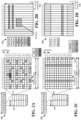
- FIG. 2A is a diagram 200 illustrating an example of a DL frame structure.
- FIG. 2B is a diagram 230 illustrating an example of channels within the DL frame structure.
- FIG. 2C is a diagram 250 illustrating an example of an UL frame structure.
- FIG. 2D is a diagram 280 illustrating an example of channels within the UL frame structure.
- Other wireless communication technologies may have a different frame structure and/or different channels.
- a frame (10 ms) may be divided into 10 equally sized subframes. Each subframe may include two consecutive time slots.
- a resource grid may be used to represent the two time slots, each time slot including one or more time concurrent resource blocks (RBs) (also referred to as physical RBs (PRBs)).
- the resource grid is divided into multiple resource elements (REs).
- RBs time concurrent resource blocks
- PRBs physical RBs
- an RB For a normal cyclic prefix, an RB contains 12 consecutive subcarriers in the frequency domain and 7 consecutive symbols (for DL, OFDM symbols; for UL, SC-FDMA symbols) in the time domain, for a total of 84 REs.
- an RB For an extended cyclic prefix, an RB contains 12 consecutive subcarriers in the frequency domain and 6 consecutive symbols in the time domain, for a total of 72 REs.
- the number of bits carried by each RE depends on the modulation scheme.
- the DL-RS may include cell-specific reference signals (CRS) (also sometimes called common RS), UE-specific reference signals (UE-RS), and channel state information reference signals (CSI-RS).
- CRS cell-specific reference signals
- UE-RS UE-specific reference signals
- CSI-RS channel state information reference signals
- FIG. 2A illustrates CRS for antenna ports 0, 1, 2, and 3 (indicated as R 0 , R 1 , R 2 , and R 3 , respectively), UE-RS for antenna port 5 (indicated as R 5 ), and CSI-RS for antenna port 15 (indicated as R).
- FIG. 2B illustrates an example of various channels within a DL subframe of a frame.
- the physical control format indicator channel (PCFICH) is within symbol 0 of slot 0, and carries a control format indicator (CFI) that indicates whether the physical downlink control channel (PDCCH) occupies 1, 2, or 3 symbols ( FIG. 2B illustrates a PDCCH that occupies 3 symbols).
- the PDCCH carries downlink control information (DCI) within one or more control channel elements (CCEs), each CCE including nine RE groups (REGs), each REG including four consecutive REs in an OFDM symbol.
- DCI downlink control information
- CCEs control channel elements
- Each CCE including nine RE groups (REGs), each REG including four consecutive REs in an OFDM symbol.
- a UE may be configured with a UE-specific enhanced PDCCH (ePDCCH) that also carries DCI.
- the ePDCCH may have 2, 4, or 8 RB pairs ( FIG. 2B shows two RB pairs, each subset including one RB pair).
- the physical hybrid automatic repeat request (ARQ) (HARQ) indicator channel (PHICH) is also within symbol 0 of slot 0 and carries the HARQ indicator (HI) that indicates HARQ acknowledgement (ACK) / negative ACK (NACK) feedback based on the physical uplink shared channel (PUSCH).
- the primary synchronization channel (PSCH) may be within symbol 6 of slot 0 within subframes 0 and 5 of a frame.
- the PSCH carries a primary synchronization signal (PSS) that is used by a UE to determine subframe/symbol timing and a physical layer identity.
- the secondary synchronization channel (SSCH) may be within symbol 5 of slot 0 within subframes 0 and 5 of a frame.
- the SSCH carries a secondary synchronization signal (SSS) that is used by a UE to determine a physical layer cell identity group number and radio frame timing. Based on the physical layer identity and the physical layer cell identity group number, the UE can determine a physical cell identifier (PCI). Based on the PCI, the UE can determine the locations of the aforementioned DL-RS.
- the physical broadcast channel (PBCH) which carries a master information block (MIB), may be logically grouped with the PSCH and SSCH to form a synchronization signal (SS) block.
- the MIB provides a number of RBs in the DL system bandwidth, a PHICH configuration, and a system frame number (SFN).
- the physical downlink shared channel (PDSCH) carries user data, broadcast system information not transmitted through the PBCH such as system information blocks (SIBs), and paging messages.
- SIBs system information blocks
- some of the REs carry demodulation reference signals (DM-RS) for channel estimation at the base station.
- the UE may additionally transmit sounding reference signals (SRS) in the last symbol of a subframe.
- SRS sounding reference signals
- the SRS may have a comb structure, and a UE may transmit SRS on one of the combs.
- the SRS may be used by a base station for channel quality estimation to enable frequency-dependent scheduling on the UL.
- FIG. 2D illustrates an example of various channels within an UL subframe of a frame.
- a physical random access channel (PRACH) may be within one or more subframes within a frame based on the PRACH configuration.
- the PRACH may include six consecutive RB pairs within a subframe.
- PRACH physical random access channel
- the PRACH allows the UE to perform initial system access and achieve UL synchronization.
- a physical uplink control channel may be located on edges of the UL system bandwidth.
- the PUCCH carries uplink control information (UCI), such as scheduling requests, a channel quality indicator (CQI), a precoding matrix indicator (PMI), a rank indicator (RI), and HARQ ACK/NACK feedback.
- UCI uplink control information
- the PUSCH carries data, and may additionally be used to carry a buffer status report (BSR), a power headroom report (PHR), and/or UCI.
- BSR buffer status report
- PHR power headroom report
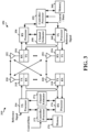
- FIG. 3 is a block diagram of a base station 310 in communication with a UE 350 in an access network.
- IP packets from the EPC 160 may be provided to a controller/processor 375.
- the controller/processor 375 implements layer 3 and layer 2 functionality.
- Layer 3 includes a radio resource control (RRC) layer
- layer 2 includes a packet data convergence protocol (PDCP) layer, a radio link control (RLC) layer, and a medium access control (MAC) layer.
- RRC radio resource control
- PDCP packet data convergence protocol
- RLC radio link control
- MAC medium access control
- the controller/processor 375 provides RRC layer functionality associated with broadcasting of system information (e.g., MIB, SIBs), RRC connection control (e.g., RRC connection paging, RRC connection establishment, RRC connection modification, and RRC connection release), inter radio access technology (RAT) mobility, and measurement configuration for UE measurement reporting; PDCP layer functionality associated with header compression / decompression, security (ciphering, deciphering, integrity protection, integrity verification), and handover support functions; RLC layer functionality associated with the transfer of upper layer packet data units (PDUs), error correction through ARQ, concatenation, segmentation, and reassembly of RLC service data units (SDUs), re-segmentation of RLC data PDUs, and reordering of RLC data PDUs; and MAC layer functionality associated with mapping between logical channels and transport channels, multiplexing of MAC SDUs onto transport blocks (TBs), demultiplexing of MAC SDUs from TBs, scheduling information reporting, error correction
- the transmit (TX) processor 316 and the receive (RX) processor 370 implement layer 1 functionality associated with various signal processing functions.
- Layer 1 which includes a physical (PHY) layer, may include error detection on the transport channels, forward error correction (FEC) coding/decoding of the transport channels, interleaving, rate matching, mapping onto physical channels, modulation/demodulation of physical channels, and MIMO antenna processing.
- the TX processor 316 handles mapping to signal constellations based on various modulation schemes (e.g., binary phase-shift keying (BPSK), quadrature phase-shift keying (QPSK), M-phase-shift keying (M-PSK), M-quadrature amplitude modulation (M-QAM)).
- BPSK binary phase-shift keying
- QPSK quadrature phase-shift keying
- M-PSK M-phase-shift keying
- M-QAM M-quadrature amplitude modulation
- Each stream may then be mapped to an OFDM subcarrier, multiplexed with a reference signal (e.g., pilot) in the time and/or frequency domain, and then combined together using an Inverse Fast Fourier Transform (IFFT) to produce a physical channel carrying a time domain OFDM symbol stream.
- the OFDM stream is spatially precoded to produce multiple spatial streams.
- Channel estimates from a channel estimator 374 may be used to determine the coding and modulation scheme, as well as for spatial processing.
- the channel estimate may be derived from a reference signal and/or channel condition feedback transmitted by the UE 350.
- Each spatial stream may then be provided to a different antenna 320 via a separate transmitter 318TX.
- Each transmitter 318TX may modulate an RF carrier with a respective spatial stream for transmission.
- each receiver 354RX receives a signal through its respective antenna 352.
- Each receiver 354RX recovers information modulated onto an RF carrier and provides the information to the receive (RX) processor 356.
- the TX processor 368 and the RX processor 356 implement layer 1 functionality associated with various signal processing functions.
- the RX processor 356 may perform spatial processing on the information to recover any spatial streams destined for the UE 350. If multiple spatial streams are destined for the UE 350, they may be combined by the RX processor 356 into a single OFDM symbol stream.
- the RX processor 356 then converts the OFDM symbol stream from the time-domain to the frequency domain using a Fast Fourier Transform (FFT).
- FFT Fast Fourier Transform
- the frequency domain signal comprises a separate OFDM symbol stream for each subcarrier of the OFDM signal.
- the symbols on each subcarrier, and the reference signal are recovered and demodulated by determining the most likely signal constellation points transmitted by the base station 310. These soft decisions may be based on channel estimates computed by the channel estimator 358.
- the soft decisions are then decoded and deinterleaved to recover the data and control signals that were originally transmitted by the base station 310 on the physical channel.
- the data and control signals are then provided to the controller/processor 359, which implements layer 3 and layer 2 functionality.
- the controller/processor 359 can be associated with a memory 360 that stores program codes and data.
- the memory 360 may be referred to as a computer-readable medium.
- the controller/processor 359 provides demultiplexing between transport and logical channels, packet reassembly, deciphering, header decompression, and control signal processing to recover IP packets from the EPC 160.
- the controller/processor 359 is also responsible for error detection using an ACK and/or NACK protocol to support HARQ operations.
- the controller/processor 359 provides RRC layer functionality associated with system information (e.g., MIB, SIBs) acquisition, RRC connections, and measurement reporting; PDCP layer functionality associated with header compression / decompression, and security (ciphering, deciphering, integrity protection, integrity verification); RLC layer functionality associated with the transfer of upper layer PDUs, error correction through ARQ, concatenation, segmentation, and reassembly of RLC SDUs, re-segmentation of RLC data PDUs, and reordering of RLC data PDUs; and MAC layer functionality associated with mapping between logical channels and transport channels, multiplexing of MAC SDUs onto TBs, demultiplexing of MAC SDUs from TBs, scheduling information reporting, error correction through HARQ, priority handling, and logical channel prioritization.
- RRC layer functionality associated with system information (e.g., MIB, SIBs) acquisition, RRC connections, and measurement reporting
- PDCP layer functionality associated with header compression
- Channel estimates derived by a channel estimator 358 from a reference signal or feedback transmitted by the base station 310 may be used by the TX processor 368 to select the appropriate coding and modulation schemes, and to facilitate spatial processing.
- the spatial streams generated by the TX processor 368 may be provided to different antenna 352 via separate transmitters 354TX. Each transmitter 354TX may modulate an RF carrier with a respective spatial stream for transmission.
- the UL transmission is processed at the base station 310 in a manner similar to that described in connection with the receiver function at the UE 350.
- Each receiver 318RX receives a signal through its respective antenna 320.
- Each receiver 318RX recovers information modulated onto an RF carrier and provides the information to a RX processor 370.
- the controller/processor 375 can be associated with a memory 376 that stores program codes and data.
- the memory 376 may be referred to as a computer-readable medium.
- the controller/processor 375 provides demultiplexing between transport and logical channels, packet reassembly, deciphering, header decompression, control signal processing to recover IP packets from the UE 350. IP packets from the controller/processor 375 may be provided to the EPC 160.
- the controller/processor 375 is also responsible for error detection using an ACK and/or NACK protocol to support HARQ operations.
- sTTI short transmission time interval
- Some such improvements may include new and improved design and implementation of a sPUCCH.
- the new design may allow intra-sTTI frequency hopping support in a slot-based shortened PUCCH (sPUCCH).
- sPUCCH slot-based shortened PUCCH
- frequency hopping within the sTTI e.g., which in some cases may correspond to a slot of the subframe, may be allowed in some configurations.
- one hop per slot may be used.
- two hops per slot may be used.
- At least one other slot-based sPUCCH format may also be supported without intra-sTTI frequency hopping.
- dynamic switching between intra-sTTI frequency hopping and no intra-sTTI frequency hopping for the same slot-based sPUCCH format may not be allowed.
- the same slot-based sPUCCH format may support both intra-sTTI frequency hopping and no intra-sTTI frequency hopping.
- a single slot sPUCCH format with intra-sTTI frequency hopping is supported.
- intra slot frequency hopping is supported and one hop per slot may be utilized, while in some other configurations two hops per slot may be utilized.
- An aspect that is taken into consideration in some configurations where intra-sTTI hopping is adopted, is the coexistence, e.g., compatibility or conformance, with a 2-symbol sPUCCH.
- the uplink layout for a 2-symbol sTTI is, e.g., [3,2,2,2,2,3].
- the first and the last parts of the PUCCH may each include 3 symbols (e.g., SC-FDM symbols or OFDM symbols), while other part(s) of the PUCCH may each include 2 SC-FDM symbols or multiples of 2 SC-FMD symbols, e.g., 2 or 4 SC-FDM symbols.
- 3 symbols e.g., SC-FDM symbols or OFDM symbols
- other part(s) of the PUCCH may each include 2 SC-FDM symbols or multiples of 2 SC-FMD symbols, e.g., 2 or 4 SC-FDM symbols.
- Some of the advantages of using such a 2-symbol sTTI layout include improved multiplexing and more efficient use of the symbols within the slot.
- a plurality of different frequency hopping patterns may be considered with a single slot sPUCCH.
- a single hop per slot of a subframe is used.
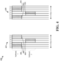
- FIG. 4 is a drawing 400 illustrating two configurations of a single slot sPUCCH and an intra-sTTI frequency hopping pattern used therewith.
- the frequency (bandwidth) is plotted in the vertical direction (along Y-axis) and the horizontal direction (X-axis) represents time.
- Drawing 400 shows a first configuration 425 of the single slot sPUCCH when the sPUCCH is in a first slot (slot 0) of a subframe and a second configuration 450 of the single slot sPUCCH when the sPUCCH is in a second slot (slot 1) of the subframe.
- the configuration/layout of an sPUCCH may be different depending on the slot index within the subframe.
- a frequency hopping pattern with 2 hops per slot is used.
- the frequency pattern shown in drawing 400 may be configured in accordance with uplink layout of the 2-symbol sTTI which may be expressed as [3, 2, 2, 2, 2, 3]. That is, when the sPUCCH is in the first slot of a subframe, the sPUCCH may be configured in a form of 3+2+2 symbols as illustrated in the configuration 425, while the sPUCCH may be configured in the form of 2+2+3 symbols when the sPUCCH is in the second slot of the subframe as illustrated in the configuration 450.
- the first and the third parts (sets of symbols) of the sPUCCH may occupy a first subband, while the middle part occupy a different subband of the frequency bandwidth.
- the first set of 3 symbols (402) corresponding to the sPUCCH are associated with a first frequency subband (subband 1)
- the next set of 2 symbols (404) corresponding to the sPUCCH are associated with a second frequency subband (subband 2)
- the last 2 symbols (406) of the sPUCCH are again in the first frequency subband.
- the resources (e.g., resource elements/subcarriers) corresponding to the first and third symbols of the set of symbols 402 in subband 1 may carry uplink control data, e.g., first UCI (shown with a dotted pattern) while the resources (e.g., subcarriers corresponding to subband 1) in the second symbol of the set of symbols 402 may carry DM-RS (diagonal line pattern), e.g., for channel estimation at the base station.
- the resources corresponding to the first symbol of the set of 2 symbols 404 corresponding to subband 2 may carry uplink control data (e.g., second UCI) while the resources of the second symbol of the set of symbols 404 may carry DM-RS.
- the resources corresponding to the first and second symbols of the set of 2 symbols 406 in subband 1 may carry uplink control data (e.g., third UCI).
- one of the symbols in the set of symbols 406 may be a DM-RS symbol (optional).
- the first UCI, the second UCI, and the third UCI may be the same.
- the second/third UCI may be a repeat/retransmission of the first UCI.
- the first UCI, the second UCI, and the third UCI may be different.
- the first set of 2 symbols (412) of the sPUCCH are associated with the first frequency subband (subband 1)
- the next set of 2 symbols (414) of the sPUCCH are associated with the second frequency subband (subband 2)
- the last set of 3 symbols (416) of the sPUCCH are again in the first frequency subband (subband 1).
- the resources corresponding to the first symbol of the set of symbols 412 in subband 1 may carry uplink control data while the resources in the second symbol of set 412 in subband 1 may carry DM-RS.
- the resources corresponding to the first symbol of the set of symbols 414 in subband 2 may carry uplink control data while the resources of the second symbol of the set of symbols 414 may carry DM-RS.
- the resources corresponding to the first and third symbols of the set of symbols 416 in subband 1 may carry uplink control data while the resources of the middle symbol of the set 416 in subband 1 may carry DM-RS.
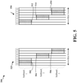
- FIG. 5 is a drawing 500 illustrating two configurations of a single slot sPUCCH and another intra-sTTI frequency hopping pattern used therewith.
- Drawing 500 illustrates a first configuration 525 of the single slot sPUCCH when the sPUCCH is in a first slot of a subframe and a second configuration 550 of the single slot sPUCCH when the sPUCCH is in a second slot of the subframe.
- the frequency hopping pattern of drawing 500 may be configured in accordance with uplink layout of the 2-symbol sTTI [3,2,2,2,2,3].
- the first set of 3 symbols (502) corresponding to the sPUCCH are in the first frequency subband (subband 1)
- the next set of 2 symbols (504) corresponding to the sPUCCH are in the second frequency subband (subband 2)
- the last set of 2 symbols (506) of the sPUCCH are in a third frequency subband (subband 3).
- the resources corresponding to the first and third symbols of the set of symbols 502 in subband 1 may carry uplink control data (shown with a dotted pattern) while the resources of the second symbol of the set of symbols 402 may carry DM-RS (diagonal line pattern.
- the resources corresponding to the first symbol of the next set of 2 symbols 504 in subband 2 may carry uplink control data while the resources of the second symbol of the set of symbols 504 may carry DM-RS.
- the resources corresponding to the first symbol of the set of 2 symbols 506 in subband 3 may carry uplink control data while the resources of the second symbol of the set of symbols 506 in subband 3 may carry DM-RS.
- the first 2 symbols (512) corresponding to the sPUCCH are in the first frequency subband (subband 1)
- the next 2 symbols (514) corresponding to the sPUCCH are in the second frequency subband (subband 2)
- the last set of 3 symbols (516) of the sPUCCH are in the third frequency subband (subband 3).
- the resources corresponding to the first symbol of the set of symbols 512 in subband 1 may carry uplink control data while the resources in the second symbol of set 512 in subband 1 may carry DM-RS.
- the resources corresponding to the first symbol of the set of symbols 514 in subband 2 may carry uplink control data while the resources of the second symbol of the set of symbols 514 may carry DM-RS.
- the resources corresponding to the first and third symbols of the set of symbols 516 in subband 3, may carry uplink control data while the resources of the middle symbol of the set 516 in subband 3 may carry DM-RS.
- each of the illustrated frequency subbands may correspond to a single RB, or may include less/more than one RB.
- the information carried by the resources of the different sets of symbols in an sPUCCH may depend on the sPUCCH format. For example, some symbols may carry uplink control information while others may carry reference signal, e.g., DM-RS, as discussed above.
- each structure may have different number of RBs, different number of DM-RSs, different DM-RS positions, different orthogonal cover code (OCC) length, etc.
- OCC orthogonal cover code
- the most suitable structure may be selected for communicating the UCI.
- a plurality of different structures may be defined for different UE conditions (e.g., channel conditions).
- each SPUCCH structure may be designed to support a certain payload size, or alternatively to support up to a maximum payload size.
- Configuring sPUCCH having various different structures and resources ensures that, e.g., the right structure/resource(s) is chosen for each UE according to the UE's condition, and that different multiplexing capacities can be achieved, e.g., to multiplex multiple UEs on a sPUCCH.
- the set of possible structures/resources may be indicated to each UE via a higher layer signaling, e.g., such as via a RRC message or in a SIB.
- the information regarding different possible structures and resources may be preconfigured at the UEs, and the base station may signal an indication of which one of the different possible structures and resources is to be used by a UE.
- the indication of a structure/resource to be used by a UE for sPUCCH may be via RRC signaling from the base station.
- the indication of the assignment of a structure/resource to be used by a UE may be either an explicit indication (e.g., a bit field in the downlink control information (DCI)), or an implicit indication, e.g., similar to a ACK/NACK resource indicator (ARI) mechanism.
- DCI downlink control information
- ARI ACK/NACK resource indicator
- a bit field in the DCI may indicate which set of structure/resources is assigned to the given UE for use.
- a 2-bit field in the DCI can indicate one of the: (structure!, resource!), (structure!, resource2), (structure2, resources), (structure2, resource4) etc.
- a structure may indicate, for example, how many RBs are to be used for the sPUCCH, how many DM-RSs can be in the sPUCCH and their positions (locations), e.g., the position/location of DM-RS symbols in the slot of sPUCCH, the OCC length across symbols in same/different subbands etc.
- each structure of a sPUCCH may support a certain maximum payload size and may be associated with a particular number of RBs, a particular number of DM-RSs, positions/locations of DM-RS within a slot, and OCC length.
- a comb structure across one or more symbols of the sPUCCH may be used.
- a number of combs per symbol may also defined and indicated as part of a structure. For example, different structures may be associated with different number of combs per symbol. The number of combs may be different across different symbols corresponding to a sPUCCH.
- the single slot sPUCCH design may be based in part on, and/or compatible with, PUCCH format 2 or 3, e.g., in a sense that in some sPUCCH configurations, each slot may have 2 DM-RS symbols similar to format 2/3.
- PUCCH format 2 or 3 e.g., in a sense that in some sPUCCH configurations, each slot may have 2 DM-RS symbols similar to format 2/3.
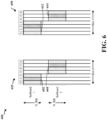
- FIG. 6 is a drawing 600 illustrating two configurations of a single slot sPUCCH and an intra-sTTI frequency hopping pattern used therewith.
- Drawing 600 shows a first configuration 625 of the single slot sPUCCH when the sPUCCH is in a first slot (slot 0) of a subframe and a second configuration 650 of the single slot sPUCCH when the sPUCCH is in a second slot (slot 1) of the subframe.
- the frequency hopping pattern of drawing 600 allows one hop per slot.
- the sPUCCH configurations with frequency hopping illustrated in FIG. 6 may be also be in accordance with uplink layout of the 2-symbol sTTI [3,2,2,2,2,3].
- the first set of 3 symbols (602) corresponding to the sPUCCH are associated with a first frequency subband (subband 1) and the next 4 symbols (604) corresponding to the sPUCCH are associated with a second frequency subband (subband 2).
- the resources corresponding to the first and third symbols, of the set of 3 symbols 602 may carry uplink control data (e.g., first UCI) while the REs corresponding to the second symbol of the set of 3 symbols 602 may carry DM-RS.
- the resources corresponding to the first, second and fourth symbols of the set of 4 symbols 604 may carry uplink control data (e.g., second UCI) while the resources of the third symbol of the set of 4 symbols 604 may carry DM-RS.
- the first set of symbols includes 4 symbols (612) and the second set includes 3 symbols (e.g., 4+3 symbol layout as the sPUCCH is in the second slot of the subframe).
- the first set of symbols 612 corresponding to the sPUCCH is associated with the first frequency subband (subband 1) and the next set of 3 symbols (614) corresponding to the sPUCCH is associated with the second frequency subband (subband 2).
- each of the illustrated frequency subbands may include a single RB or may include less/more than one RB.
- N_RB number of RBs indicated in the figure may include one RB or less/more than one RB.
- the structure of the single slot sPUCCH in configuration 625 is different than the structure of the single slot sPUCCH in configuration 650, e.g., in terms of the position/location of the DM-RS. While it may not be apparent from the drawing, the structures may also differ in terms of number of combs per symbol, symbols over which OCC is used, the OCC length across the symbols, etc.
- a given sPUCCH configuration may be based on slot index of the subframe.
- the sPUCCH layout may be of the form of 3+4 symbols.
- the sPUCCH layout may be of the form of 4+3 symbols.
- FIG. 7 illustrates a drawing 700 showing another set of configurations of a single slot sPUCCH that may be used by a UE (e.g., UE 104) for communicating UCI. While the same one hop per slot frequency hopping pattern as shown in FIG. 6 may be used in the sPUCCH configurations 725 and 750, the structure and/or format of the single slot sPUCCH in the configurations shown in FIG. 7 is different from the ones shown in FIG. 6 .
- the resources corresponding to the first and third symbols of the set of symbols 702 of the sPUCCH may carry uplink control data, e.g., first UCI (shown with dotted pattern) while the resources corresponding to the second symbol of the set of symbols 702 may carry DM-RS (shown with diagonal pattern).
- the resources corresponding to the first and fourth symbols of the set of symbols 704 (associated with subband 2) may carry uplink control data, e.g., second UCI, while the resources of the second and third symbols of the set of symbols 704 may carry DM-RS.
- the first UCI and the second UC may be the same.
- the second UCI may be a repeat/retransmission of the first UCI.
- the first and second UCI may be different.
- the resources corresponding to the first and fourth symbols of the set of symbols 712 may carry uplink control data while the resources of the second and third symbols may carry DM-RS.
- the resources corresponding to the first and third symbols, of the set of symbols 714 may carry uplink control data while the resources of the second symbol of the set 714 may carry DM-RS.
- a plurality of different structures there may be a plurality of different structures.
- there may be two different sPUCCH structures e.g., a first structure and a second structure
- the first structure may be defined with no intra-slot frequency hopping and with OCC
- the second structure may be defined with intra-slot frequency hopping and with no OCC.
- a single slot sPUCCH having such a first structure may have OCC applied across the symbols in the slot
- a single slot sPUCCH having such a second structure may have no OCC across the symbols in the slot.
- different symbols of the sPUCCH may carry uplink control data and reference signals.
- the format and/or structure to be used for the sPUCCH may be indicated via RRC signaling from the base station (e.g., base station 102/180) or such indication may be received in the downlink control information from the base station.
- uplink data carried by a data symbol of the sPUCCH may be repeated in a subsequent data symbol. From FIGs. 4-7 , it may be appreciated that various design configurations and structures of a single slot sPUCCH are possible. As discussed above, the structure and resources for an sPUCCH may be configured based on the UE condition and/or given payload size of the uplink control information to be transmitted.
- OCC of length 2 across the 2 data symbols in the set of symbols 602 in the same subband (subband 1) may be utilized for more protection against interference and noise.
- OCC of length 2 across the 2 data symbols in the set of symbols 702 in the same subband (subband 1) may be used and OCC of length 2 across the 2 DM-RS symbols in the set 704 may be used.
- the waveform generation may be the same or similar to the legacy PUCCH format 1a or 1b, e.g., modulated symbol may be mapped to the data symbol in the same or similar manner as in PUCCH format 1a or 1b.
- having the same waveform generation is not necessary and may be different than that used in legacy PUCCH formats.
- a 1-slot sPUCCH may be based on legacy PUCCH format 3, and in such configurations there may be no OCC across symbols in different subbands, e.g., when intra-slot frequency hopping is adopted and UCI carried in the different sets of symbols is frequency hopped.
- a first approach no hopping is used for the sPUCCH formats carrying large payload sizes.
- intra-sTTI frequency hopping is not used, e.g., when the UCI payload is large.
- a DM-RS symbol may be needed for each subband over which hopping occurs. This may be considered wasteful, more so in situations where the payload to be carried is already large, overhead is extensive and greater number of symbols are needed for carrying the data. In such cases, having to give up at least one symbol per subband (for DM-RS) may be considered wasteful enough to discourage use of frequency hopping.
- frequency hopping is used even for sPUCCH carrying large payload sizes.
- hopping may be used.
- FIG. 6 illustrates an example of such a configuration of the sPUCCH where frequency hopping is utilized and the sPUCCH format may be based on PUCCH format 2 or 3, e.g., in terms of waveform generation and/or the number of DM-RS symbols per slot.
- FIG. 8 is a drawing 800 illustrating an IFDMA based 2-symbol sPUCCH.
- the 2-symbol sPUCCH includes a DM-RS symbol 802 and data symbol 804 which may extend to N RBs.
- a comb structure is assumed over the DM-RS and data symbols. That is, over each symbol a comb structure of different combs may be used. For instance, in the illustrated example, the comb structure over each symbol may include four combs which repeat throughout the symbol, where each comb is represented in the figure using a different pattern.
- a first UE may be assigned a first comb and may transmit its DM-RS and/or data on the comb while another UE may get a different comb and transmit its DM-RS and/or data on the different comb to maintain orthogonality.
- the UEs may be assigned the same combs but different cyclic shifts, or they may be assigned different combs in order for the UE transmissions to be orthogonal. While the number of combs across the two symbols shown in FIG. 8 is the same, e.g., 4, in accordance with an aspect, the number of combs may be different across symbols. For example, the number of combs from DM-RS symbol 802 to the data symbol 804 may be different. Similarly, the number of combs from a data symbol to another data symbol may be different, or from one DM-RS symbol to another DM-RS symbol may be different.
- a sequence based transmission over a DM-RS symbol using combs may be performed.
- different combs/cyclic shifts may be assigned to different users.
- a UE may transmit the DM-RS sequence on the assigned comb.
- the use of combs in addition to the cyclic shift provides another dimension of orthogonality and allows for better multiplexing of different users.
- sequence based data transmission over a data symbol using combs may be performed for small payload sizes, e.g., BPSK/QPSK symbols.
- BPSK/QPSK symbols For example, consider that each UE may be assigned 4 cyclic shifts and a comb and the UE has to transmit a 2-bit ACK/NACK. The UE may select a cyclic shift to use based on the data sequence to transmit, e.g., whether the UE has to transmit a 0001 or a 1011, and then use the assigned comb to transmit the data sequence.
- the base station may receive the transmission, detect the cyclic shift chosen by the UE for the transmission, and determine what combination of ACK/NACK was meant to be transmitted by the UE, e.g., ACK/NACK, ACK/ACK, NACK/ACK or other combination.
- a discrete Fourier transform (DFT) based transmission is used over the assigned combs.
- DFT discrete Fourier transform
- a single slot sPUCCH with 7 symbols may be used with a comb structure over each of the symbols of the sPUCCH.
- the same data and DM-RS structures (or a variation of these) as discussed above with regard to the 2 symbol sPUCCH of FIG. 8 may be used to design a single slot sPUCCH.
- the number of combs per symbol can also be indicated to the UE.
- a UE may be able to determine how many combs per data and/or DM-RS symbols are there and which comb is assigned to the UE.
- different number of combs may be used over different symbols as discussed above, e.g., number of combs used over one symbol may be different than a number of combs over another symbol of the sPUCCH.
- FIG. 9 is a flowchart 900 of a method of wireless communication.
- the method may be performed by an apparatus (e.g., such as the UE 104, 350, apparatus 1002, 1002'). Some of the operations may be optional as represented by dashed boxes and may be performed in some but not all embodiments.
- the apparatus is simply referred to as the UE.
- the UE may receive an indication from a base station (e.g., base station 102/180) assigning a first structure to the UE to be used for an sPUCCH, e.g., for transmitting UCI of a given payload size.
- the first structure may be one of a plurality of structures. As discussed supra, there may be various different structures for a given UCI payload size. In one aspect, for an sPUCCH of a given format (e.g., 1, 1a, 1b, 2, 3, 4), there may be a plurality of different structures. Each structure may be characterized by a number of RBs, number of DM-RSs, DM-RS locations, orthogonal cover code (OCC) length, etc.
- OCC orthogonal cover code
- the base station may select a most suitable structure of the sPUCCH with a given format for the UE for communicating the UCI. For example, in some configurations, a number of various different structures and sPUCCH formats may be known to the UE (e.g., preconfigured/stored in the UE or the base station may configure the UE with this information via signaling).
- the UE may already know which sPUCCH format to use based on its UCI payload size (e.g., 1, 1a, 1b for up to two bits of UCI, 2/3 for more than 2 bits, 3 and 4 for even larger payload and so on), the UE may need an indication from the base station as to which structure (for the sPUCCH) to use as there may be more than one structure for the same payload size. Accordingly, in an aspect, the base station may signal the UE which one of the structures is to be used by the UE for an sPUCCH that may carry the UCI from the UE. Thus, at 902 the UE may receive such an indication from the base station regarding the structure to be used for a given UCI payload size.
- the indication of a structure to be used by a UE for the sPUCCH may be received via RRC signaling from the base station.
- the indication may be an explicit indication in the DCI, or an implicit indication (e.g., similar to the ART mechanism).
- the UE may transmit first UCI in a first set of resources within a first set of symbols of a sPUCCH within a slot of a subframe.
- the sPUCCH may be a single slot sPUCCH such as the ones shown in FIGs 4-7 .
- the sPUCCH may be considered to be the single slot sPUCCH 625 (e.g., sPUCCH may be configured in slot 0 of a subframe).
- the first set of resources within the first set of symbols may be the resources, e.g., REs and/or subcarriers of the subband 1, corresponding to set of symbols 602.
- the first UCI transmitted in the first set of resources within the first set of symbols may include uplink control data carried in the first and third symbols of the set of symbols 602 while the second symbol of the set of symbols 602 may carry DM-RS.
- the sPUCCH may have the first structure that is indicated to be used in the signaling from the base station as discussed with respect to 902.
- the UE may transmit second UCI in a second set of resources within a second set of symbols of the sPUCCH within the slot, where the second set of symbols may be subsequent to the first set of symbols.
- the second set of resources within the second set of symbols of the sPUCCH may be the resources corresponding to set of symbols 604.
- a number of symbols in the first set of symbols and a number of symbols in the second set of symbols is based on the slot index of the slot within the subframe.
- a number of symbols in the first set of symbols and a number of symbols in the second set of symbols of the single slot sPUCCH may be based on whether the slot (in which the sPUCCH is configured) is a first slot of the subframe or a second slot of the subframe.
- the slot in which the sPUCCH is configured
- the number of symbols in the first set 602 is three and the number of symbols in the second set 604 is four (e.g., sPUCCH with 3+4 symbol layout).
- the number of symbols in the first set 612 of the sPUCCH 650 is four and the number of symbols in the second set of symbols 614 of the sPUCCH is three (e.g., sPUCCH with 4+3 symbol layout).
- the sPUCCH carrying the first and second UCI has the first structure that is different from a second structure of a second sPUCCH in a different slot, and the first and second structures may be different with respect to at least one of a number of resource blocks, a number of DM-RS, positions for the DM-RS, comb structure, or orthogonal cover code (OCC) length.
- OCC orthogonal cover code
- sPUCCH structures there may be a plurality of different sPUCCH structures for a given UCI payload size, and two structures may differ from each other in terms of one or more of the number of resource blocks, the number of DM-RS, position/location for the DM-RS within the slot of the sPUCCH, comb structure/number of combs per symbol in the sPUCCH, or OCC length, etc.
- the second sPUCCH carries the same size UCI payload but the second sPUCCH is transmitted in a different slot of the subframe than the second sPUCCH may have a different structure than the sPUCCH.
- the sPUCCH 725 that occupies a first slot (slot 0) of a subframe has a structure that is different than the structure of sPUCCH 750 that occupies a different slot, i.e., the second slot (slot 1) of the subframe (e.g., in terms of position/location of DM-RS).
- the number of symbols in the first set of symbols and the number of symbols in the second set of symbols may be further based on whether an intra-slot frequency hopping is used with the sPUCCH.
- the number of symbols in the first set of symbols and the number of symbols in the second set of symbols in the sPUCCH may depend on a number of frequency hops within the slot. For example, as discussed with regard to FIGs.
- the number of symbols corresponding to different parts of the sPUCCH may be different when a single hop (one hop per slot) frequency hopping is used (e.g., as illustrated in FIG.s 6-7 ) than when a double hop (two hops per slot) frequency hopping is used (e.g., as illustrated in FIG.s 4-5 ).
- the first set of symbols may include three symbols and the second set of symbols may include four symbols when the slot (occupied by the sPUCCH) is the first slot of the subframe and a single hop per slot intra-slot frequency hopping is used (e.g., as in example sPUCCH configurations 625 and 725).
- a first symbol and a third symbol of the first set of three symbols of the sPUCCH may carry the first UCI while a second symbol of the first set of three symbols may carry DM-RS.
- a first and fourth symbol of the second set of four symbols of the sPUCCH may carry the second UCI while a second symbol and a third symbol of the second set of four symbols may each carry DM-RS.
- the first and third symbols of the set three symbols 702 carry UCI while the second symbol carries DM-RS
- the first and fourth symbols of the set of 4 symbols 704 carry UCI while the second and third symbols of the set 704 carry DM-RS.
- the first set of symbols of the sPUCCH may include four symbols and the second set of symbols may include three symbols when the slot (occupied by the sPUCCH) is the second slot of the subframe and the single hop per slot intra-slot frequency hopping is used (e.g., as in example sPUCCH configurations 650 and 750).
- a first symbol and a fourth symbol of the first set of four symbols of the sPUCCH may carry the first UCI while a second symbol and a third symbol of the first set of four symbols may each carry DM-RS.
- a first and third symbol of the second set of three symbols of the sPUCCH may carry the second UCI while a second symbol of the second set of three symbols may carry DM-RS.
- the first set of symbols may include three symbols and the second set of symbols may include two symbols when the slot (occupied by the sPUCCH) is the first slot of the subframe and a double hop per slot intra-slot frequency hopping is used (e.g., as in example sPUCCH configurations 425 and 525), whereas the first set of symbols and the second set of symbols may each include two symbols when the slot is the second slot of the subframe and the double hop per slot intra-slot frequency hopping is used (e.g., as in example sPUCCH configurations 450 and 550).
- the method of flowchart 900 may further include operation illustrated at 908 where the UE may transmit third UCI in a third set of resources within a third set of symbols of the sPUCCH within the slot.
- the third set of symbols may be subsequent to the second set of symbols and may include two symbols when the slot is the first slot of the subframe (e.g., as illustrated in configurations 425 and 525) and three symbols when the slot is the second slot of the subframe (e.g., as illustrated in configurations 450 and 550).
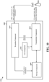
- FIG. 10 is a conceptual data flow diagram 1000 illustrating the data flow between different means/components in an exemplary apparatus 1002.
- the apparatus includes a reception component 1004, a storage component 1006, a UCI component 1008, and a transmission component 1010.
- the reception component 1004 may be configured to receive RRC configuration, downlink control information, data, and/or other information from the base station 1050.
- the signals/information may be received by the reception component 1004 in accordance with the methods discussed supra including the method of flowchart 900.
- the received signals/information may be provided to one or more components of the apparatus 1002 for further processing and use in performing various operations in accordance with methods and techniques discussed supra.
- the apparatus 1002 may receive configuration information (e.g., as RRC configuration) from the base station 1050.
- the configuration information may include information indicating various sPUCCH formats, various different possible sets of structures and resources that are defined and may be used for sPUCCH.
- each structure may be associated with a particular number of RBs, a particular number of DM-RSs, positions/locations of DM-RS within a slot, and OCC length across data/DM-RS symbols in same/different subbands.
- the received configuration information may then be stored in the storage component (e.g., memory) 1006. In some other configurations, such information may be preconfigured in the apparatus 1002.
- the reception component 1004 may receive, from the base station 1050, an indication assigning a first structure to the apparatus to be used for an sPUCCH, e.g., for transmitting UCI of a given payload size from the apparatus 1002.
- the first structure may be one of the various different structures that may be known to the apparatus 1002 (e.g., preconfigured or based on the earlier RRC configuration from the base station). With the received indication, the apparatus 1002 determines which particular structure (for the sPUCCH) for the given UCI payload size is to be used as there may be a plurality of structures for the same payload size.
- the indication of the structure may be received via RRC signaling from the base station 1050, or the indication may be included in the DCI received from the base station via the reception component.
- the reception component 1004 may further receive an indication from the base station 1050 indicating whether intra slot frequency hopping is to be used in the sPUCCH for transmission of UCI.
- reception component 1004 may provide the received indication of the structure to the transmission component 1010 for use in controlling the transmission of the sPUCCH in accordance with the indicated structure.
- the sPUCCH may carry the UCI generated by the UCI component 1006.
- the UCI may include information such as, for example, scheduling request, a CQI, a precoding matrix indicator, a rank indicator, and HARQ ACK/NACK feedback.
- the transmission component 1010 may be configured to transmit uplink control information, data and/or other signaling to the base station 1050 in accordance with the features of the disclosed methods (e.g., flowchart 900), and techniques and configurations described supra in connection with FIGs. 4-8 .
- the transmission component may transmit UCI in a single slot sPUCCH that may be configured in accordance with the indicated structure.
- the transmission component 1010 may transmit first UCI in a first set of resources within a first set of symbols of a sPUCCH within a slot.
- the transmission component 1010 may be further configured to transmit second UCI in a second set of resources within a second set of symbols of the sPUCCH within the slot, where the second set of symbols is subsequent to the first set of symbols.
- a number of symbols in the first set of symbols and a number of symbols in the second set of symbols is based on whether the slot is a first slot of a subframe or a second slot of the subframe.
- the number of symbols in the first set of symbols and the second set of symbols corresponding to the single slot sPUCCH may be based on whether the sPUCCH is configured in a first slot (slot 0) or the second slot (slot 1) of a subframe.
- the sPUCCH carrying the first and second UCI transmitted by the transmission component 1010 sPUCCH has the first structure (e.g., based on the indication from the base station 1050).
- the first structure associated with the sPUCCH is different from a second structure of a second sPUCCH in a different slot (e.g., an sPUCCH that occupies a different slot of the subframe).
- the first and second structures may differ with respect to at least one of a number of resource blocks, a number of DM-RS, positions/locations of the DM-RS, comb structure, or OCC length.
- the number of symbols in the first set of symbols and the number of symbols in the second set of symbols is further based on a number of frequency hops within the slot when an intra-slot frequency hopping is used with the sPUCCH, e.g., intra slot frequency hopping enabled for hopping the UCI across different bands.
- the first set of symbols includes three symbols and the second set of symbols includes four symbols when the slot is the first slot of the subframe and a single hop per slot intra-slot frequency hopping is used.
- the transmission component 1010 may be configured to transmit the first UCI in a first symbol and a third symbol of the first set of symbols of the sPUCCH and transmit DM-RS in a second symbol of the first set of symbols.
- the transmission component 1010 in such configurations may be further configured to transmit the second UCI in a first symbol and a fourth symbol of the second set of symbols of the sPUCCH and transmit DM-RS in a second symbol and a third symbol of the second set of symbols.
- the first set of symbols may include four symbols and the second set of symbols includes three symbols.
- the transmission component 1010 may be further configured to transmit the first UCI in a first symbol and a fourth symbol of the first set of symbols of the sPUCCH, and transmit DM-RS in a second symbol and a third symbol of the first set of symbols.
- the transmission component 1010 may be further configured to transmit the second UCI in a first symbol and a third symbol of the second set of symbols of the sPUCCH, and transmit DM-RS in a second symbol of the second set of symbols.
- the first set of symbols includes three symbols and the second set of symbols includes two symbols when the slot is the first slot of the subframe and 2 hops per slot intra-slot frequency hopping is used.
- the first set of symbols and the second set of symbols each includes two symbols when the slot is the second slot of the subframe and 2 hops per slot intra-slot frequency hopping is used.
- the transmission component 1010 may be further configured to transmit third UCI in a third set of resources within a third set of symbols of the sPUCCH within the slot.
- the third set of symbols may be subsequent to the second set of symbols and include two symbols when the slot is the first slot of the subframe (e.g., as illustrated in sPUCCH 425 and 525).
- the second set of symbols may include three symbols (e.g., as illustrated in sPUCCH 450 and 550).
- the transmission component 1010 may transmit UCI and DM-RS in a sPUCCH in accordance with a selected format and assigned structure for the sPUCCH.
- the transmission component 1010 may transmit UCI in sPUCCH with various different configurations and designs such as those illustrated as examples in FIGs. 4-8 .
- the apparatus may include additional components that perform each of the blocks of the algorithm in the aforementioned flowchart of FIG. 9 .
- each block in the aforementioned flowcharts of FIG. 9 may be performed by a component and the apparatus may include one or more of those components.
- the components may be one or more hardware components specifically configured to carry out the stated processes/algorithm, implemented by a processor configured to perform the stated processes/algorithm, stored within a computer-readable medium for implementation by a processor, or some combination thereof.
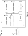
- FIG. 11 is a diagram 1100 illustrating an example of a hardware implementation for an apparatus 1002' employing a processing system 1114.
- the processing system 1114 may be implemented with a bus architecture, represented generally by the bus 1124.
- the bus 1124 may include any number of interconnecting buses and bridges depending on the specific application of the processing system 1114 and the overall design constraints.
- the bus 1124 links together various circuits including one or more processors and/or hardware components, represented by the processor 1104, the components 1004, 1006, 1008, 1010 and the computer-readable medium/memory 1106.
- the storage component 1006 may be a part of the computer-readable medium/memory.
- the bus 1124 may also link various other circuits such as timing sources, peripherals, voltage regulators, and power management circuits, which are well known in the art, and therefore, will not be described any further.
- the processing system 1114 may be coupled to a transceiver 1110.
- the transceiver 1110 is coupled to one or more antennas 1120.
- the transceiver 1110 provides a means for communicating with various other apparatus over a transmission medium.
- the transceiver 1110 receives a signal from the one or more antennas 1120, extracts information from the received signal, and provides the extracted information to the processing system 1114, specifically the reception component 1004.
- the transceiver 1110 receives information from the processing system 1114, specifically the transmission component 1010, and based on the received information, generates a signal to be applied to the one or more antennas 1120.
- the processing system 1114 includes a processor 1104 coupled to a computer-readable medium/memory 1106.
- the processor 1104 is responsible for general processing, including the execution of software stored on the computer-readable medium/memory 1106.
- the software when executed by the processor 1104, causes the processing system 1114 to perform the various functions described supra for any particular apparatus.
- the computer-readable medium/memory 1106 may also be used for storing data that is manipulated by the processor 1104 when executing software.
- the processing system 1114 further includes at least one of the components 1004, 1006, 1008, 1010.
- the components may be software components running in the processor 1104, resident/stored in the computer readable medium/memory 1106, one or more hardware components coupled to the processor 1104, or some combination thereof.
- the processing system 1114 may be a component of the UE 350 and may include the memory 360 and/or at least one of the TX processor 368, the RX processor 356, and the controller/processor 359.
- the apparatus 1002/1002' for wireless communication includes means for transmitting first UCI in a first set of resources within a first set of symbols of a sPUCCH within a slot, and transmitting second UCI in a second set of resources within a second set of symbols of the sPUCCH within the slot, the second set of symbols being subsequent to the first set of symbols.
- the first set of symbols includes three symbols and the second set of symbols includes four symbols when the slot is the first slot of the subframe and a single hop per slot intra-slot frequency hopping is used.
- the means for transmitting is configured to transmit the first UCI in a first symbol and a third symbol of the first set of symbols of the sPUCCH and a DM-RS in a second symbol of the first set of symbols carries DM-RS. Furthermore, in one configuration, the means for transmitting is further configured to transmit the second UCI in a first symbol and a fourth symbol of the second set of symbols of the sPUCCH and a DM-RS in each of a second symbol and a third symbol of the second set of symbols.
- the first set of symbols includes four symbols and the second set of symbols includes three symbols when the slot is the second slot of the subframe and the single hop per slot intra-slot frequency hopping is used.
- the means for transmitting is configured to transmit the first UCI in a first symbol and a fourth symbol of the first set of symbols of the sPUCCH and a DM-RS in each of a second symbol and a third symbol of the first set of symbols.
- the means for transmitting is further configured to transmit the second UCI in a first symbol and a third symbol of the second set of symbols of the sPUCCH and a DM-RS in a second symbol of the second set of symbols.
- the means for transmitting is further configured to transmit third UCI in a third set of resources within a third set of symbols of the sPUCCH within the slot.
- the third set of symbols is subsequent to the second set of symbols and includes two symbols when the slot is the first slot of the subframe.
- the third set of symbols may include three symbols when the slot is the second slot of the subframe.
- the sPUCCH may have a first structure that is different from a second structure of a second sPUCCH in a different slot, where the first and second structures being different with respect to at least one of a number of resource blocks, a number of DM-RS, positions for the DM-RS, comb structure, or OCC length.
- the apparatus 1002/1002' may further include means for receiving, from a base station, an indication assigning the first structure to the apparatus to be used for the sPUCCH, where the first structure may be one of a plurality of structures.
- the aforementioned means may be one or more of the aforementioned components of the apparatus 1002 and/or the processing system 1114 of the apparatus 1002' configured to perform the functions recited by the aforementioned means.
- the processing system 1114 may include the TX Processor 368, the RX Processor 356, and the controller/processor 359.
- the aforementioned means may be the TX Processor 368, the RX Processor 356, and the controller/processor 359 configured to perform the functions recited by the aforementioned means.
- an exemplary UE (e.g., UE 104/350/apparatus 1002') implementing the method of flowchart 900 may include a memory and at least one processor coupled to the memory.
- the at least one processor may be configured to: transmit first UCI in a first set of resources within a first set of symbols of a sPUCCH within a slot, and transmit second UCI in a second set of resources within a second set of symbols of the sPUCCH within the slot, the second set of symbols being subsequent to the first set of symbols.
- a number of symbols in the first set of symbols and a number of symbols in the second set of symbols is based on whether the slot is a first slot of a subframe or a second slot of the subframe.
- the UE may further include a communication interface including one or more antennas.
- the at least one processor maybe further configured to transmit the sPUCCH including the UCI (e.g., first and second UCI) via the one or more antennas wirelessly over the air, and receive signaling from a base station (e.g., RRC message, DCI, etc. described supra ) via the one or more antennas.
- a base station e.g., RRC message, DCI, etc. described supra
Claims (8)
- Procédé de communication sans fil d'un équipement utilisateur, UE, comprenant les étapes consistant à :transmettre (904) des premières informations de contrôle de liaison montante, UCI, dans un premier ensemble de ressources à l'intérieur d'un premier ensemble de symboles d'un canal de contrôle de liaison montante physique raccourci, sPUCCH, à l'intérieur d'un intervalle de temps ; ettransmettre (906) des deuxièmes UCI dans un deuxième ensemble de ressources dans un deuxième ensemble de symboles du sPUCCH dans l'intervalle de temps, le deuxième ensemble de symboles étant postérieur au premier ensemble de symboles ;dans lequel un nombre de symboles dans le premier ensemble de symboles et un nombre de symboles dans le deuxième ensemble de symboles est basé sur le fait que l'intervalle de temps est un premier intervalle d'une sous-trame ou un deuxième intervalle de la sous-trame,dans lequel le premier ensemble de symboles comprend trois symboles et le deuxième ensemble de symboles comprend quatre symboles lorsque l'intervalle de temps est le premier intervalle de la sous-trame et qu'une procédure de saut de fréquence intra-intervalle à un seul saut par intervalle est utilisée avec le sPUCCH ; etdans lequel le premier ensemble de symboles comprend quatre symboles et le deuxième ensemble de symboles comprend trois symboles lorsque l'intervalle de temps est le deuxième intervalle de la sous-trame et la procédure de saut de fréquence intra-intervalle à un seul saut par intervalle est utilisée avec le sPUCCH ;dans lequel, lorsque l'intervalle de temps est le premier intervalle de la sous-trame, un premier symbole et un troisième symbole du premier ensemble de symboles du sPUCCH porte les premières UCI tandis qu'un deuxième symbole du premier ensemble de symboles porte les DM-RS, et dans lequel un premier symbole et un quatrième symbole du deuxième ensemble de symboles du sPUCCH portent les deuxièmes UCI tandis qu'un deuxième symbole et un troisième symbole du deuxième ensemble de symboles portent chacun les DM-RS ; oudans lequel, lorsque l'intervalle de temps est le deuxième intervalle de la sous-trame, un premier symbole et un quatrième symbole du premier ensemble de symboles du sPUCCH portent les premières UCI tandis qu'un deuxième symbole et un troisième symbole du premier ensemble de symboles portent chacun les DM-RS, et dans lequel un premier symbole et un troisième symbole du deuxième ensemble de symboles du sPUCCH portent les deuxièmes UCI tandis qu'un deuxième symbole du deuxième ensemble de symboles porte les DM-RS.
- Procédé selon la revendication 1, dans lequel le sPUCCH a une première structure qui est différente d'une deuxième structure d'un deuxième sPUCCH dans un intervalle différent, la première et la deuxième structures étant différentes par rapport à au moins un parmi un certain nombre de blocs de ressources, un certain nombre des positions pour les signaux de référence de démodulation, DM-RS, une structure de peigne, ou une longueur de code de couverture orthogonal, OCC.
- Procédé selon la revendication 1, dans lequel le premier ensemble de symboles comprend trois symboles et le deuxième ensemble de symboles comprend deux symboles lorsque l'intervalle de temps est le premier intervalle de la sous-trame et qu'une procédure de saut de fréquence intra-intervalle à double saut par intervalle est utilisée ; et
dans lequel le premier ensemble de symboles et le deuxième ensemble de symboles comprennent chacun deux symboles lorsque l'intervalle de temps est le deuxième intervalle de la sous-trame et la procédure de saut de fréquence intra-intervalle à double saut par intervalle est utilisée. - Procédé selon la revendication 3, en outre comprenant les étapes consistant à :
transmettre des troisièmes UCI dans un troisième ensemble de ressources à l'intérieur d'un troisième ensemble de symboles du sPUCCH à l'intérieur de l'intervalle de temps, le troisième ensemble de symboles étant postérieur au deuxième ensemble de symboles et comprenant deux symboles lorsque l'intervalle de temps est le premier intervalle de la sous-trame et comprenant trois symboles lorsque l'intervalle de temps est le deuxième intervalle de la sous-trame. - Procédé selon la revendication 2, comprenant en outre l'étape consistant à :
recevoir, d'une station de base, une indication attribuant la première structure à l'UE à utiliser pour le sPUCCH, la première structure étant l'une d'une pluralité de structures. - Procédé selon la revendication 5, dans lequel l'indication est reçue dans un message de contrôle de ressource radio (RRC) de la station de base, ou dans un champ binaire d'informations de contrôle de liaison descendante reçues de la station de base.
- Appareil de communication sans fil, comprenant :une mémoire ; etau moins un processeur couplé à la mémoire et configurés pour :transmettre (904) des premières informations de contrôle de liaison montante, UCI, dans un premier ensemble de ressources à l'intérieur d'un premier ensemble de symboles d'un canal de contrôle de liaison montante physique raccourci, sPUCCH, à l'intérieur d'un intervalle de temps ; ettransmettre (906) des deuxièmes UCI dans un deuxième ensemble de ressources dans un deuxième ensemble de symboles du sPUCCH dans l'intervalle de temps, le deuxième ensemble de symboles étant postérieur au premier ensemble de symboles ;dans lequel un nombre de symboles dans le premier ensemble de symboles et un nombre de symboles dans le deuxième ensemble de symboles est basé sur le fait que l'intervalle de temps est un premier intervalle d'une sous-trame ou un deuxième intervalle de la sous-trame,dans lequel le premier ensemble de symboles comprend trois symboles et le deuxième ensemble de symboles comprend quatre symboles lorsque l'intervalle de temps est le premier intervalle de la sous-trame et qu'une procédure de saut de fréquence intra-intervalle à un seul saut par intervalle est utilisée avec le sPUCCH ; etdans lequel le premier ensemble de symboles comprend quatre symboles et le deuxième ensemble de symboles comprend trois symboles lorsque l'intervalle de temps est le deuxième intervalle de la sous-trame et la procédure de saut de fréquence intra-intervalle à un seul saut par intervalle est utilisée avec le sPUCCH ;dans lequel, lorsque l'intervalle de temps est le premier intervalle de la sous-trame, un premier symbole et un troisième symbole du premier ensemble de symboles du sPUCCH porte les premières UCI tandis qu'un deuxième symbole du premier ensemble de symboles porte les DM-RS, et dans lequel un premier symbole et un quatrième symbole du deuxième ensemble de symboles du sPUCCH portent les deuxièmes UCI tandis qu'un deuxième symbole et un troisième symbole du deuxième ensemble de symboles portent chacun les DM-RS ; oudans lequel, lorsque l'intervalle de temps est le deuxième intervalle de la sous-trame, un premier symbole et un quatrième symbole du premier ensemble de symboles du sPUCCH portent les premières UCI tandis qu'un deuxième symbole et un troisième symbole du premier ensemble de symboles portent chacun les DM-RS, et dans lequel un premier symbole et un troisième symbole du deuxième ensemble de symboles du sPUCCH portent les deuxièmes UCI tandis qu'un deuxième symbole du deuxième ensemble de symboles porte les DM-RS.
- Un support lisible par ordinateur stockant un code exécutable par ordinateur, comprenant un code pour :transmettre (904) des premières informations de contrôle de liaison montante, UCI, dans un premier ensemble de ressources à l'intérieur d'un premier ensemble de symboles d'un canal de contrôle de liaison montante physique raccourci, sPUCCH, à l'intérieur d'un intervalle de temps ; ettransmettre (906) des deuxièmes UCI dans un deuxième ensemble de ressources dans un deuxième ensemble de symboles du sPUCCH dans l'intervalle de temps, le deuxième ensemble de symboles étant postérieur au premier ensemble de symboles ;dans lequel un nombre de symboles dans le premier ensemble de symboles et un nombre de symboles dans le deuxième ensemble de symboles est basé sur le fait que l'intervalle de temps est un premier intervalle d'une sous-trame ou un deuxième intervalle de la sous-trame,dans lequel le premier ensemble de symboles comprend trois symboles et le deuxième ensemble de symboles comprend quatre symboles lorsque l'intervalle de temps est le premier intervalle de la sous-trame et qu'une procédure de saut de fréquence intra-intervalle à un seul saut par intervalle est utilisée avec le sPUCCH ; etdans lequel le premier ensemble de symboles comprend quatre symboles et le deuxième ensemble de symboles comprend trois symboles lorsque l'intervalle de temps est le deuxième intervalle de la sous-trame et la procédure de saut de fréquence intra-intervalle à un seul saut par intervalle est utilisée avec le sPUCCH ;dans lequel, lorsque l'intervalle de temps est le premier intervalle de la sous-trame, un premier symbole et un troisième symbole du premier ensemble de symboles du sPUCCH porte les premières UCI tandis qu'un deuxième symbole du premier ensemble de symboles porte les DM-RS, et dans lequel un premier symbole et un quatrième symbole du deuxième ensemble de symboles du sPUCCH portent les deuxièmes UCI tandis qu'un deuxième symbole et un troisième symbole du deuxième ensemble de symboles portent chacun les DM-RS ; oudans lequel, lorsque l'intervalle de temps est le deuxième intervalle de la sous-trame, un premier symbole et un quatrième symbole du premier ensemble de symboles du sPUCCH portent les premières UCI tandis qu'un deuxième symbole et un troisième symbole du premier ensemble de symboles portent chacun les DM-RS, et dans lequel un premier symbole et un troisième symbole du deuxième ensemble de symboles du sPUCCH portent les deuxièmes UCI tandis qu'un deuxième symbole du deuxième ensemble de symboles porte les DM-RS.
Applications Claiming Priority (3)
| Application Number | Priority Date | Filing Date | Title |
|---|---|---|---|
| US201762476653P | 2017-03-24 | 2017-03-24 | |
| US15/892,054 US10405305B2 (en) | 2017-03-24 | 2018-02-08 | Single slot short PUCCH with support for intra slot frequency hopping |
| PCT/US2018/017604 WO2018175011A1 (fr) | 2017-03-24 | 2018-02-09 | Pucch court à intervalle unique avec support pour saut de fréquence intra-intervalle |
Publications (3)
| Publication Number | Publication Date |
|---|---|
| EP3602907A1 EP3602907A1 (fr) | 2020-02-05 |
| EP3602907B1 true EP3602907B1 (fr) | 2023-09-13 |
| EP3602907C0 EP3602907C0 (fr) | 2023-09-13 |
Family
ID=63581295
Family Applications (1)
| Application Number | Title | Priority Date | Filing Date |
|---|---|---|---|
| EP18707803.5A Active EP3602907B1 (fr) | 2017-03-24 | 2018-02-09 | Pucch court à intervalle unique avec support pour saut de fréquence intra-intervalle |
Country Status (9)
| Country | Link |
|---|---|
| US (1) | US10405305B2 (fr) |
| EP (1) | EP3602907B1 (fr) |
| JP (1) | JP7098650B2 (fr) |
| KR (1) | KR102628930B1 (fr) |
| CN (1) | CN110431793B (fr) |
| BR (1) | BR112019019817A2 (fr) |
| SG (1) | SG11201907508WA (fr) |
| TW (1) | TWI755481B (fr) |
| WO (1) | WO2018175011A1 (fr) |
Families Citing this family (15)
| Publication number | Priority date | Publication date | Assignee | Title |
|---|---|---|---|---|
| US10110405B2 (en) * | 2015-11-05 | 2018-10-23 | Qualcomm Incorporated | System and method for narrowband uplink single tone transmissions |
| ES2899307T3 (es) * | 2017-05-05 | 2022-03-10 | Ericsson Telefon Ab L M | Señalización de múltiples transmisiones de TTI corto |
| US10568118B2 (en) * | 2017-07-12 | 2020-02-18 | Samsung Electronics Co., Ltd. | Method and apparatus for transmitting control and data signals based on a short TTI in a wireless cellular communication system |
| EP3713313B1 (fr) * | 2017-11-17 | 2022-04-27 | Datang Mobile Communications Equipment Co., Ltd. | Procédé de régulation de puissance de liaison montante, et terminal de communication mobile |
| WO2019100406A1 (fr) * | 2017-11-27 | 2019-05-31 | 华为技术有限公司 | Procédé et dispositif de transmission de données |
| CN111587605B (zh) * | 2018-01-12 | 2023-09-08 | 诺基亚技术有限公司 | 用于保持针对非许可无线频谱的信道占用率的上行链路信道调度 |
| JP7237862B2 (ja) * | 2018-02-15 | 2023-03-13 | 株式会社Nttドコモ | 端末、無線通信方法、基地局及びシステム |
| JP7121796B2 (ja) | 2018-05-10 | 2022-08-18 | エルジー エレクトロニクス インコーポレイティド | 無線通信システムにおいて無線信号の送受信方法及び装置 |
| US11184201B2 (en) * | 2019-05-15 | 2021-11-23 | Astrapi Corporation | Communication devices, systems, software and methods employing symbol waveform hopping |
| US11477760B2 (en) * | 2019-12-19 | 2022-10-18 | Qualcomm Incorporated | Frequency diversity techniques for single frequency networks |
| WO2021155586A1 (fr) * | 2020-02-07 | 2021-08-12 | Qualcomm Incorporated | Améliorations de signal de référence de sondage (srs) |
| WO2021176418A1 (fr) * | 2020-03-06 | 2021-09-10 | Telefonaktiebolaget Lm Ericsson (Publ) | Systèmes et procédés relatifs à des répétitions de sous-intervalle de canal physique de commande de liaison montante (pucch) |
| US20220046642A1 (en) * | 2020-08-06 | 2022-02-10 | Asustek Computer Inc. | Method and apparatus for resource allocation in a wireless communication system |
| CN114598434A (zh) * | 2020-12-03 | 2022-06-07 | 华为技术有限公司 | 数据传输方法及装置 |
| US11646912B2 (en) * | 2021-08-17 | 2023-05-09 | Qualcomm Incorporated | Techniques to facilitate phase jump estimation for sidelink DMRS bundling |
Family Cites Families (24)
| Publication number | Priority date | Publication date | Assignee | Title |
|---|---|---|---|---|
| US1702784A (en) * | 1929-02-19 | Oil-atomizing device | ||
| US8861467B2 (en) * | 2010-07-26 | 2014-10-14 | Lg Electronics Inc. | Method and device for transmitting sounding reference signal and extended uplink control information in wireless communication system |
| KR101285398B1 (ko) * | 2010-09-08 | 2013-07-10 | 엘지전자 주식회사 | 무선 통신 시스템에서 제어 정보의 전송 방법 및 장치 |
| US9172513B2 (en) * | 2010-10-11 | 2015-10-27 | Qualcomm Incorporated | Resource assignments for uplink control channel |
| WO2012148162A2 (fr) * | 2011-04-25 | 2012-11-01 | 엘지전자 주식회사 | Procédé pour émettre-recevoir un signal de référence dans un système d'accès sans fil et terminal associé |
| WO2012150836A2 (fr) * | 2011-05-03 | 2012-11-08 | 엘지전자 주식회사 | Procédé de transmission d'informations de contrôle dans un système de communication sans fil et dispositif correspondant |
| CN107241178B (zh) * | 2011-10-20 | 2021-01-26 | Lg电子株式会社 | 在无线通信系统中接收控制信息的方法和装置 |
| US9313779B2 (en) * | 2012-07-27 | 2016-04-12 | Intel Corporation | Uplink control information transmission with large number of bits |
| EP2946630B1 (fr) * | 2013-01-16 | 2020-05-27 | Interdigital Patent Holdings, Inc. | Génération et réception de signaux de découverte |
| EP2954633A1 (fr) | 2013-02-07 | 2015-12-16 | Nokia Solutions and Networks Oy | Duplexage par répartition dans le temps |
| CN104105138B (zh) | 2013-04-03 | 2019-04-05 | 中兴通讯股份有限公司 | 数据信道的传输、接收处理方法及装置 |
| ITFI20130292A1 (it) * | 2013-11-30 | 2015-05-31 | Futura Spa | Dispositivo per il controllo dell'affilatura di lame a nastro. |
| US10516517B2 (en) * | 2015-01-29 | 2019-12-24 | Intel IP Corporation | System and methods for support of frequency hopping for UEs with reduced bandwidth support |
| AR103887A1 (es) | 2015-03-09 | 2017-06-14 | ERICSSON TELEFON AB L M (publ) | Canal pucch breve en canal spucch de enlace ascendente |
| CN106341890B (zh) * | 2015-07-08 | 2019-09-17 | 电信科学技术研究院 | 一种物理信道传输方法及设备 |
| US10327232B2 (en) * | 2015-09-02 | 2019-06-18 | Qualcomm Incorporated | Techniques for allocating time and frequency resources to an uplink channel to carry uplink control information used for narrowband communication |
| EP3348012A4 (fr) * | 2015-09-11 | 2019-04-03 | Intel IP Corporation | Transmission d'informations de commande de liaison montante dans des systèmes sans fil |
| US10362605B2 (en) * | 2016-01-21 | 2019-07-23 | Telefonaktiebolaget Lm Ericsson (Publ) | Systems and methods for multiplexing scheduling requests in unlicensed bands |
| EP3437401B1 (fr) | 2016-03-31 | 2021-08-04 | Panasonic Intellectual Property Corporation of America | Configuration de sous-trame spéciale destinée à une réduction de latence |
| US10743306B2 (en) * | 2016-05-13 | 2020-08-11 | Telefonaktiebolaget Lm Ericsson (Publ) | Adaptive transmission time interval length |
| US10492184B2 (en) * | 2016-12-09 | 2019-11-26 | Samsung Electronics Co., Ltd. | Multiplexing control information in a physical uplink data channel |
| EP3556161A4 (fr) * | 2016-12-13 | 2020-06-24 | Sharp Kabushiki Kaisha | Stations de base, équipements d'utilisateurs, et procédés de communication associés |
| US11166262B2 (en) * | 2017-01-05 | 2021-11-02 | FG Innovation Company Limited | Long physical uplink control channel (PUCCH) design for 5th generation (5G) new radio (NR) |
| CN110663236B (zh) * | 2017-03-23 | 2022-08-30 | 株式会社Ntt都科摩 | 用户终端以及无线通信方法 |
-
2018
- 2018-02-08 US US15/892,054 patent/US10405305B2/en active Active
- 2018-02-09 CN CN201880019012.5A patent/CN110431793B/zh active Active
- 2018-02-09 BR BR112019019817A patent/BR112019019817A2/pt unknown
- 2018-02-09 KR KR1020197030993A patent/KR102628930B1/ko active IP Right Grant
- 2018-02-09 WO PCT/US2018/017604 patent/WO2018175011A1/fr active Application Filing
- 2018-02-09 JP JP2019551445A patent/JP7098650B2/ja active Active
- 2018-02-09 EP EP18707803.5A patent/EP3602907B1/fr active Active
- 2018-02-09 TW TW107104679A patent/TWI755481B/zh active
- 2018-02-09 SG SG11201907508W patent/SG11201907508WA/en unknown
Also Published As
| Publication number | Publication date |
|---|---|
| JP2020511847A (ja) | 2020-04-16 |
| US20180279296A1 (en) | 2018-09-27 |
| US10405305B2 (en) | 2019-09-03 |
| CN110431793B (zh) | 2021-12-03 |
| KR102628930B1 (ko) | 2024-01-23 |
| BR112019019817A2 (pt) | 2020-04-22 |
| JP7098650B2 (ja) | 2022-07-11 |
| EP3602907A1 (fr) | 2020-02-05 |
| CN110431793A (zh) | 2019-11-08 |
| WO2018175011A1 (fr) | 2018-09-27 |
| SG11201907508WA (en) | 2019-10-30 |
| TW201836422A (zh) | 2018-10-01 |
| EP3602907C0 (fr) | 2023-09-13 |
| TWI755481B (zh) | 2022-02-21 |
| KR20190127902A (ko) | 2019-11-13 |
Similar Documents
| Publication | Publication Date | Title |
|---|---|---|
| EP3602907B1 (fr) | Pucch court à intervalle unique avec support pour saut de fréquence intra-intervalle | |
| US11012283B2 (en) | Single carrier waveform data transmission and reception based on configurable DFT window | |
| US20210084701A1 (en) | Methods and apparatus for device-to-device feedback | |
| EP3707948B1 (fr) | Conception sur mappage de dmrs de pdcch et attribution de ressources de coreset | |
| US11528110B2 (en) | Methods and apparatus related to demodulation reference signal design and related signaling | |
| EP3440798B9 (fr) | Commande de liaison descendante destinée aux transmissions de signal de référence de démodulation | |
| US11381367B2 (en) | System and method for self-contained subslot bundling | |
| EP3317993B1 (fr) | Optimisation d'attribution d'ordonnancement pour des communications dispositif à dispositif | |
| EP3571874B1 (fr) | Procédés et appareil liés au suivi temporel dans des systèmes à porteuses multiples | |
| CN111373823B (zh) | 用于信号重复冲突的优先级规则 | |
| WO2019080837A1 (fr) | Sélection et configuration d'un ensemble de ressources pucch | |
| JP2020503712A (ja) | 低いピーク対平均電力比を有する復調基準信号および粒度を伴う割振り情報 | |
| CN114450911B (zh) | 具有减少的开销的解调参考信号 | |
| WO2018169637A1 (fr) | Ajustement de mcs/rang lors du multiplexage de données dans une région de commande | |
| JP2020537410A (ja) | Nrにおけるprachおよびpusch分離のための異なる方法 | |
| CN112970295B (zh) | 对ne-dc中的潜在nr ul传输的指示 | |
| US10873347B2 (en) | Channel bit interleaver design for polar coding chain | |
| CN117157935A (zh) | 用于初始接入信息的ssb、coreset、sib信号块 |
Legal Events
| Date | Code | Title | Description |
|---|---|---|---|
| STAA | Information on the status of an ep patent application or granted ep patent |
Free format text: STATUS: UNKNOWN |
|
| STAA | Information on the status of an ep patent application or granted ep patent |
Free format text: STATUS: THE INTERNATIONAL PUBLICATION HAS BEEN MADE |
|
| PUAI | Public reference made under article 153(3) epc to a published international application that has entered the european phase |
Free format text: ORIGINAL CODE: 0009012 |
|
| STAA | Information on the status of an ep patent application or granted ep patent |
Free format text: STATUS: REQUEST FOR EXAMINATION WAS MADE |
|
| 17P | Request for examination filed |
Effective date: 20191018 |
|
| AK | Designated contracting states |
Kind code of ref document: A1 Designated state(s): AL AT BE BG CH CY CZ DE DK EE ES FI FR GB GR HR HU IE IS IT LI LT LU LV MC MK MT NL NO PL PT RO RS SE SI SK SM TR |
|
| AX | Request for extension of the european patent |
Extension state: BA ME |
|
| DAV | Request for validation of the european patent (deleted) | ||
| DAX | Request for extension of the european patent (deleted) | ||
| STAA | Information on the status of an ep patent application or granted ep patent |
Free format text: STATUS: EXAMINATION IS IN PROGRESS |
|
| 17Q | First examination report despatched |
Effective date: 20210422 |
|
| STAA | Information on the status of an ep patent application or granted ep patent |
Free format text: STATUS: EXAMINATION IS IN PROGRESS |
|
| GRAP | Despatch of communication of intention to grant a patent |
Free format text: ORIGINAL CODE: EPIDOSNIGR1 |
|
| STAA | Information on the status of an ep patent application or granted ep patent |
Free format text: STATUS: GRANT OF PATENT IS INTENDED |
|
| INTG | Intention to grant announced |
Effective date: 20230414 |
|
| GRAS | Grant fee paid |
Free format text: ORIGINAL CODE: EPIDOSNIGR3 |
|
| GRAA | (expected) grant |
Free format text: ORIGINAL CODE: 0009210 |
|
| STAA | Information on the status of an ep patent application or granted ep patent |
Free format text: STATUS: THE PATENT HAS BEEN GRANTED |
|
| AK | Designated contracting states |
Kind code of ref document: B1 Designated state(s): AL AT BE BG CH CY CZ DE DK EE ES FI FR GB GR HR HU IE IS IT LI LT LU LV MC MK MT NL NO PL PT RO RS SE SI SK SM TR |
|
| REG | Reference to a national code |
Ref country code: GB Ref legal event code: FG4D |
|
| REG | Reference to a national code |
Ref country code: CH Ref legal event code: EP |
|
| REG | Reference to a national code |
Ref country code: DE Ref legal event code: R096 Ref document number: 602018057424 Country of ref document: DE |
|
| REG | Reference to a national code |
Ref country code: IE Ref legal event code: FG4D |
|
| U01 | Request for unitary effect filed |
Effective date: 20231004 |
|
| U07 | Unitary effect registered |
Designated state(s): AT BE BG DE DK EE FI FR IT LT LU LV MT NL PT SE SI Effective date: 20231013 |
|
| PG25 | Lapsed in a contracting state [announced via postgrant information from national office to epo] |
Ref country code: GR Free format text: LAPSE BECAUSE OF FAILURE TO SUBMIT A TRANSLATION OF THE DESCRIPTION OR TO PAY THE FEE WITHIN THE PRESCRIBED TIME-LIMIT Effective date: 20231214 |
|
| PG25 | Lapsed in a contracting state [announced via postgrant information from national office to epo] |
Ref country code: RS Free format text: LAPSE BECAUSE OF FAILURE TO SUBMIT A TRANSLATION OF THE DESCRIPTION OR TO PAY THE FEE WITHIN THE PRESCRIBED TIME-LIMIT Effective date: 20230913 Ref country code: NO Free format text: LAPSE BECAUSE OF FAILURE TO SUBMIT A TRANSLATION OF THE DESCRIPTION OR TO PAY THE FEE WITHIN THE PRESCRIBED TIME-LIMIT Effective date: 20231213 Ref country code: HR Free format text: LAPSE BECAUSE OF FAILURE TO SUBMIT A TRANSLATION OF THE DESCRIPTION OR TO PAY THE FEE WITHIN THE PRESCRIBED TIME-LIMIT Effective date: 20230913 Ref country code: GR Free format text: LAPSE BECAUSE OF FAILURE TO SUBMIT A TRANSLATION OF THE DESCRIPTION OR TO PAY THE FEE WITHIN THE PRESCRIBED TIME-LIMIT Effective date: 20231214 |
|
| U20 | Renewal fee paid [unitary effect] |
Year of fee payment: 7 Effective date: 20240111 |
|
| PG25 | Lapsed in a contracting state [announced via postgrant information from national office to epo] |
Ref country code: IS Free format text: LAPSE BECAUSE OF FAILURE TO SUBMIT A TRANSLATION OF THE DESCRIPTION OR TO PAY THE FEE WITHIN THE PRESCRIBED TIME-LIMIT Effective date: 20240113 |