EP3602104B1 - Optisches scansystem - Google Patents
Optisches scansystem Download PDFInfo
- Publication number
- EP3602104B1 EP3602104B1 EP18713936.5A EP18713936A EP3602104B1 EP 3602104 B1 EP3602104 B1 EP 3602104B1 EP 18713936 A EP18713936 A EP 18713936A EP 3602104 B1 EP3602104 B1 EP 3602104B1
- Authority
- EP
- European Patent Office
- Prior art keywords
- optical
- lens
- mirror
- rotor
- axis
- Prior art date
- Legal status (The legal status is an assumption and is not a legal conclusion. Google has not performed a legal analysis and makes no representation as to the accuracy of the status listed.)
- Active
Links
Images
Classifications
-
- G—PHYSICS
- G01—MEASURING; TESTING
- G01S—RADIO DIRECTION-FINDING; RADIO NAVIGATION; DETERMINING DISTANCE OR VELOCITY BY USE OF RADIO WAVES; LOCATING OR PRESENCE-DETECTING BY USE OF THE REFLECTION OR RERADIATION OF RADIO WAVES; ANALOGOUS ARRANGEMENTS USING OTHER WAVES
- G01S7/00—Details of systems according to groups G01S13/00, G01S15/00, G01S17/00
- G01S7/48—Details of systems according to groups G01S13/00, G01S15/00, G01S17/00 of systems according to group G01S17/00
- G01S7/481—Constructional features, e.g. arrangements of optical elements
- G01S7/4811—Constructional features, e.g. arrangements of optical elements common to transmitter and receiver
- G01S7/4812—Constructional features, e.g. arrangements of optical elements common to transmitter and receiver transmitted and received beams following a coaxial path
-
- G—PHYSICS
- G01—MEASURING; TESTING
- G01S—RADIO DIRECTION-FINDING; RADIO NAVIGATION; DETERMINING DISTANCE OR VELOCITY BY USE OF RADIO WAVES; LOCATING OR PRESENCE-DETECTING BY USE OF THE REFLECTION OR RERADIATION OF RADIO WAVES; ANALOGOUS ARRANGEMENTS USING OTHER WAVES
- G01S7/00—Details of systems according to groups G01S13/00, G01S15/00, G01S17/00
- G01S7/48—Details of systems according to groups G01S13/00, G01S15/00, G01S17/00 of systems according to group G01S17/00
- G01S7/481—Constructional features, e.g. arrangements of optical elements
- G01S7/4817—Constructional features, e.g. arrangements of optical elements relating to scanning
-
- G—PHYSICS
- G02—OPTICS
- G02B—OPTICAL ELEMENTS, SYSTEMS OR APPARATUS
- G02B26/00—Optical devices or arrangements for the control of light using movable or deformable optical elements
- G02B26/08—Optical devices or arrangements for the control of light using movable or deformable optical elements for controlling the direction of light
- G02B26/0875—Optical devices or arrangements for the control of light using movable or deformable optical elements for controlling the direction of light by means of one or more refracting elements
-
- G—PHYSICS
- G02—OPTICS
- G02B—OPTICAL ELEMENTS, SYSTEMS OR APPARATUS
- G02B26/00—Optical devices or arrangements for the control of light using movable or deformable optical elements
- G02B26/08—Optical devices or arrangements for the control of light using movable or deformable optical elements for controlling the direction of light
- G02B26/10—Scanning systems
Definitions
- the present invention relates to an optical scanning system.
- Current scanning systems in particular biaxial, rotating 3D laser scanners, so-called macro scanners, in which the optical axes of the transmitting and receiving units run parallel to one another at a certain distance, have a certain size. This applies both to macro scanners in which a mirror or a mirror system rotates and to macro scanners in which the transmitting and receiving units are arranged parallel to one another on the rotor.
- a particularly flat design with a low height and small rotor diameter is advantageous.
- One approach to reducing the size of a macro scanner is to partially guide the transmit and receive beam paths over the same lens. Since the optical axes of the transmit and receive units outside the sensor are identical, such scanners can also be called coaxial.
- a coaxial macro scanner is known in which a receiving lens is simultaneously used as a collimation lens for a transmission path.
- a disadvantage of the approach disclosed there is that the transmission beam cannot be expanded to a maximum lens diameter and collimated at the same time, which would be advantageous for increased transmission power and thus an increased range while ensuring eye safety.
- the diameter of the receiving apparatus is smaller than the rotor diameter.
- a laser scanner with a rotor and a lens mounted on the rotor is known from the DE102014101312B3 known.
- the DE102012102244B4 and the DE102013215627A1 reveal additional optical scanning systems.
- the EP1562055A2 discloses a scanning system according to the preamble of claim 1.
- the AT507684A4 discloses a scanning system comprising a lens rotating about an axis.
- the DE199288958A1 discloses a scanning system with a substantially spherical lens.
- the optical scanning system comprises a rotor which is designed to rotate about a rotation axis during a scanning process, an optical lens which is arranged on the rotor such that the lens lies on the rotation axis, an optical transmitting unit which is arranged on the rotor and is designed to emit a scanning beam in the direction of an optical axis of the lens and an optical receiving unit which is arranged on the rotor and comprises a detector which is designed to receive a reflected scanning beam, wherein the detector is arranged such that the reflected scanning beam is focused on the detector by means of the lens.
- Both the optical transmitting unit and the optical receiving unit are arranged on the rotor. This means that there is a mechanical connection between the optical transmitting unit and the rotor and between the optical receiving unit and the rotor, so that when the rotor rotates, the optical transmitting unit and the optical receiving unit are also moved about the axis of rotation. Since the optical lens is also arranged on the rotor, it rotates with the rotor about the axis of rotation.
- the rotor is preferably a circular disk.
- the optical lens, the optical transmitting unit and the optical receiving unit are preferably arranged on a common side of the rotor.
- the aperture of the lens has a significant impact on the sensitivity of the optical scanning system. It is therefore advantageous if the lens is as large as possible.
- the lens which is a particularly large component of the optical scanning system, a minimal space for rotation.
- the optical scanning system can thus be designed to be particularly compact, particularly in terms of its height and diameter.
- the optical scanning system according to the invention enables a maximum reception aperture, which is directly dependent on a diameter of the rotor. This makes it possible to create an optical scanning system with a particularly long range with small dimensions of the optical scanning system. Since the rotor with the units located on it rotates around the axis of rotation, a measurement over 360° in a scanning plane, e.g. horizontally, is possible.
- optical scanning system is therefore created whose receiving aperture corresponds to the rotor diameter and whose transmitting beam is widened to increase the transmitting power while at the same time ensuring eye safety.
- the optical scanning system according to the invention also has the advantage that it is easy to adjust. This means that particularly large optical elements can be used, which makes it easier to control tolerances or only has a relatively small influence on the quality of the optical scanning system. Since the scanning system is a coaxial scanning system, tolerances with respect to the rotor are of little relevance.
- the optical system is also inexpensive to manufacture because only a minimal number of optical elements are used. In particular, if the lens has a through-opening in its center or a mounting base on the surface, this can be used for low-tolerance pressing or adjustment, including bonding to transmitting and receiving elements.
- the optical lens is arranged in such a way that a center of gravity of the lens lies on the axis of rotation.
- the lens is thus arranged in such a way that it rotates about its center of gravity when the rotor rotates.
- the center of gravity is a center of mass of the lens or a geometric center of gravity of the lens.
- the center of gravity is particularly preferably both a center of mass and a geometric center of gravity of the lens.
- An outer circumference of the lens defines an enveloping surface during rotation around the axis of rotation and the optical transmitting unit and the optical receiving unit are arranged on the rotor in such a way that an area of the optical transmitting unit and/or the optical receiving unit is arranged within the volume defined by the envelope surface,
- the optical transmitting unit and the optical receiving unit are arranged on the rotor in such a way that a point on the optical lens that is furthest away from the axis of rotation is further away from the axis of rotation than a point on the optical receiving unit and the optical transmitting unit.
- the envelope surface is a surface of a body of rotation that is formed when the lens rotates around the axis of rotation. This is especially true if this consideration is made for a single plane that is perpendicular to the axis of rotation. In simple terms, this means that the transmitting unit and the optical receiving unit are arranged in a space around the optical lens that is required for rotation of the optical lens. However, since the receiving unit and the transmitting unit rotate with the lens, no collision occurs. A particularly compact optical scanning system can thus be created.
- optical axis of the lens is perpendicular to the axis of rotation. This creates a particularly large field of view for the optical scanning system, for example in a horizontal plane.
- the optical receiving unit comprises a first mirror, wherein the first mirror is arranged such that the reflected scanning beam is directed to the detector after passing through the lens by the first mirror. This makes it possible for a receiving beam path to find space between the lens and detector, since this is folded using the first mirror.
- the optical receiving unit comprises further lenses and mirrors.
- the first mirror has a focusing surface, in particular a curved surface.
- the first mirror is thus curved. In this way, aberrations of the lens can be partially compensated.
- the optical transmission unit comprises an optical emitter and a second mirror, wherein the second mirror is arranged such that the scanning beam emitted by the optical emitter is deflected by the second mirror in the direction of the optical axis of the lens.
- the optical emitter is preferably a laser, in particular a laser diode.
- the optical transmission unit includes a collimation lens.
- the collimation lens is integrated into the optical scanning system in a space-saving manner.
- the optical scanning system can thus be easily optimized for a specific scanning distance.
- the collimation lens is in particular a lens of a lens arrangement by means of which a single scanning beam or several scanning beams are collimated.
- optical receiving unit and/or the optical transmitting unit comprises an optical filter.
- Such filters enable the sensitivity of the optical scanning system to be achieved while maintaining a consistently small design.
- optical scanning system is a coaxial macro scanner.
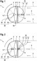
- Figure 1 shows an optical scanning system 1 according to the invention in accordance with a first embodiment of the invention.
- the optical scanning system 1 is shown in a sectional image along a first sectional plane.
- a rotation axis of the optical scanning system is perpendicular to the first sectional plane shown.
- the optical scanning system 1 is a coaxial macro scanner. This means that a scanning beam 4 emitted by the optical scanning system 1 has a parallel axis, identical in this first embodiment, to a reflected scanning beam 5 received by the optical scanning system 1.
- the optical scanning system 1 comprises a rotor 2, an optical lens 3, an optical transmitting unit 10 and an optical receiving unit 20.
- the rotor 2 is designed to rotate about a rotation axis 6 during a scanning process.
- the rotor 2 is a circular disk and the rotation axis 6 is perpendicular to a circular surface of the rotor 2 and passes through a center point of the circular surface of the rotor 2.
- the rotor 2 can have a different shape in alternative embodiments.
- the rotor 2 can consist of individual elements which form a holder for further elements of the optical scanning system 1, in particular for the optical lens 3, the optical transmitting unit 10 and/or the optical receiving unit 20.
- the rotor 2 preferably has recesses which enable the rotor 2 and the components arranged thereon to be balanced so that an imbalance during rotation is avoided.
- the optical scanning system 1 comprises a motor which drives the rotor 2 to rotate the rotation axis 6.
- the optical lens 3 is arranged on the rotor 2 in such a way that a center of gravity 7 of the optical lens 3 lies on the rotation axis 6. Since a point of the optical lens 3 lies on the rotation axis 6, the optical lens 3 is arranged on the rotation axis.
- the optical lens 3 is, for example, a biconvex lens in this first embodiment. A geometric center of gravity and a center of mass of the optical lens 3 falls on a common center of gravity 7.
- the optical lens 3 has a lens diameter that corresponds to a diameter of the rotor 2.
- the optical lens 3 is arranged centrally on the rotor 2.
- An optical axis 8 of the lens 3 is aligned such that it is perpendicular to the axis of rotation 6.
- the rotation axis 6 is shown as a point, since it is derived from the Figure 1 shown plane.
- the optical axis 8 of the lens 3 thus lies in a plane which is parallel to a plane in which the rotor 2 rotates.
- the optical transmission unit 10 is arranged on the rotor 2 and is designed to emit a scanning beam 4 in the direction of the optical axis 8 of the lens 3.
- the optical transmission unit 10 comprises an optical emitter 11, which is a laser diode, and a collimation lens 12.
- the emitter 11 is arranged on a first side of the optical lens 3 above the rotor 2.
- the optical emitter 11 is arranged on the optical axis 8 of the optical lens 3.
- the optical emitter 11 is aligned such that it emits a laser beam that spreads away from the lens 3 along the optical axis 8 of the lens 3.
- the laser beam emitted by the optical emitter 11 is the scanning beam 4.
- the scanning beam 4 Before the scanning beam 4 is emitted into an environment of the optical scanning system 1, it hits the collimation lens 12, which is arranged in front of the optical emitter 11.
- a lens arrangement is arranged which comprises several collimation lenses.
- a widening of the scanning beam 4 can be defined by a distance between the collimation lens 12 and the optical emitter 11 or by a lens curvature of the collimation lens 12. Since the optical emitter 11 and the collimation lens 12 are arranged one behind the other on the optical axis 8 of the lens 3, only a minimal area of the lens 3 is shaded by the optical transmission unit 10.
- the optical scanning system 1 further comprises the optical receiving unit 20, which is arranged on the rotor 2 and comprises a detector 21, which is designed to receive a reflected scanning beam 5, wherein the detector 21 is arranged such that the reflected scanning beam 5 is focused on the detector 21 by means of the optical lens 3.
- the optical receiving unit 20 comprises a first mirror 22.
- the first mirror 22 is arranged in such a way that the reflected scanning beam 5 is directed to the detector 21 after passing through the lens 3 by the first mirror 22.
- further optical elements can optionally be arranged between the lens 3 and the first mirror 22. Further optical elements, in particular further lenses and/or mirrors, can also optionally be arranged between the first mirror 22 and the detector 21.
- the optical receiving unit 20 further comprises an optical filter 23.
- the optical filter 23 is arranged on the first side of the lens 3, wherein the optical filter 23 is arranged between the transmitting unit 10 and the optical lens 3.
- the optical filter 23 extends over an entire surface of the optical lens 3.
- the optical filter 23 is selected such that it is only permeable to light with a wavelength that lies in a wavelength range around the wavelength of the scanning beam 4.
- the first mirror 22 is arranged on a second side of the optical lens 3, which is a side opposite the first side of the optical lens 3.
- the first mirror 22 is a concave mirror.
- the first mirror 22 has individual flat surfaces, each of which is aligned differently.
- the first mirror 22 redirects the light of the reflected scanning beam 5 that falls on it in the direction of the detector 21 and focuses it on it.
- the detector 21 is a so-called sensor array. This means that the detector 21 has a surface on which a large number of photo sensors are arranged.
- the detector 21 is arranged on the second side of the optical lens 3. An active surface of the detector 21 is aligned such that it is directed away from the optical lens 3.
- the detector 21 is arranged in a center of a surface of the optical lens 3, i.e. in front of its center of gravity 7.
- the scanning beam 4 was emitted by the optical transmission unit 10 and thus by the optical scanning system 1, it is reflected by objects in the vicinity of the optical scanning system 1. If this is the case, it is thrown back as a reflected scanning beam 5.
- the reflected scanning beam 5 is thus less focused than the scanning beam 4.
- the reflected scanning beam 5 is thrown back from the direction in which the scanning beam 4 was emitted shortly before. A minimal movement of the rotor 2 due to its Rotation was neglected in this assumption.
- the reflected scanning beam 5 thus hits the optical lens 3 and is tapered by the latter. This tapered reflected scanning beam 5 hits the first mirror 22 and is reflected by the latter.
- the reflected scanning beam 5 is further tapered and focused on the detector 21.
- the reflected scanning beam 5 is thus directed through the first mirror 22 to the detector 21 after passing through the lens 3.
- the first mirror 22 is designed as a concave mirror, it has a focusing surface which is a curved surface.
- the curved surface is the reflective surface of the first mirror 22, which is arranged such that it lies on a side of the first mirror 22 that is on the side of the optical lens 3.
- the first embodiment shown in Figure 1 shows a particularly compact optical scanning system 1.
- the optical receiving unit 20 and the optical transmitting unit 10 are arranged particularly close to the optical lens 3.
- the optical scanning system 1 is designed in such a way that the optical transmitting unit 10 and the optical receiving unit 20 are arranged on the rotor in such a way that an area of the optical transmitting unit 10 and the optical receiving unit 20 are arranged within an envelope surface 9.
- the envelope surface 9 is defined by an outer circumference of the lens 3 when the optical lens 3 rotates about the axis of rotation 6. If the Figure 1 If the optical lens 3 shown is set in rotation, it is perceived as a sphere when rotating quickly, since the optical lens 3 has a circular outer circumference.
- the spherical surface is the envelope surface 9 of the rotating optical lens 3.
- the envelope surface 9 in the sectional image shown is thus a circle which runs through the outermost points 41, 42 on the outer circumference of the optical lens 3.
- the optical transmitting unit 10 and the optical receiving unit 20 are arranged completely within this circle in the first sectional plane shown and thus completely within the envelope surface 9.
- both the transmitting unit 10 and the detector 21 are located in the optical axis 8 of the optical lens 3 and thus of the optical sensor system 1.
- the optical axis 8 is an axis that passes through the center of the optical lens 3.
- An optical filter 23, in particular a bandpass filter, or other optical filters can optionally be placed between the optical lens 3 and the transmitting unit 10.
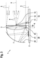
- Figure 2 shows a representation of an optical scanning system 1 according to a second embodiment of the invention.
- the second embodiment of the invention corresponds essentially to the first embodiment of the invention.
- the first cutting surface is shown, which is also shown in Figure 1 is shown.
- the second embodiment of the invention differs from the first embodiment of the invention in that the detector 21 and the optical emitter 11 are arranged on the surface of the rotor 2.
- the emitter 11 is arranged such that the scanning beam 5 is emitted parallel to the rotation axis 6.
- a second mirror 13 is arranged on the first side of the optical lens 3 in the area of the center of the surface of the optical lens 3. This is preferably attached to the optical lens 3.
- the second mirror 13 is at a 45° angle to the scanning beam 4 emitted by the emitter 11.
- the scanning beam 4 is therefore deflected by 90° and then runs along the optical axis 8 of the optical lens 3.
- the detector 21 is arranged on the second side of the optical lens 3 on the surface of the rotor 2, with an active surface of the detector 21 directed away from the rotor 2.
- a position and curvature of the first mirror 22 and a curvature of the first mirror 22 are selected accordingly.
- the optical emitter 11 and the detector 21 are thus arranged outside the lens surface of the optical lens 8 in a direction defined by the optical axis 8 of the optical lens 3. This prevents the lens from being shadowed by the optical emitter 11 and the detector 21.
- a small deflection mirror the second mirror 13, is used in the middle of the optical lens 3, which can optionally also be curved.
- This deflection mirror directs the scanning beam 4 in the direction of the optical axis 8 of the optical line 3 and produces the desired vertical divergence.
- the optionally curved first mirror 22 in the receiving beam path is inclined in this second embodiment so that the receiving beams can be focused on the detector 21.
- the number of lenses in the receiving path can be increased if necessary to improve the imaging quality, for example by arranging another lens in front of the detector 21.
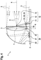
- Figure 3 shows the optical scanning system 1 according to the second embodiment of the invention.
- the optical scanning system 1 is shown in a sectional image along a second sectional plane in which the rotation axis 6 lies.
- FIG. 3 it can be seen that the second mirror 13 is attached to the optical filter 23. This eliminates the need for additional mounting elements for the second mirror 13. Furthermore, a collimation lens 12 is arranged in the scanning beam 4 between the optical emitter 11 and the second mirror 13. This embodiment thus enables the scanning beam 4 to be adapted for specific scanning areas. If the scanning beam 4 is emitted by the optical emitter 11, it passes through the collimation lens 12 and strikes the second mirror 13. By appropriately inclining the second mirror 13 with respect to the emitted scanning beam 4, the latter is aligned along the optical axis 8 of the lens 3.
- the second mirror 13 is thus arranged such that the scanning beam 4 emitted by the optical emitter 11 is deflected by the second mirror 13 in the direction of the optical axis 8 of the lens 3. It can be seen that the optical lens 3 is arranged on a mount 30.
- Figure 4 is a representation of an optical scanning system 1 according to a third embodiment of the invention.
- the third embodiment of the invention corresponds essentially to the second embodiment of the invention.
- Figure 4 the second cutting plane is shown, which is also shown in Figure 3 is shown.
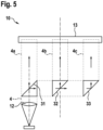
- the scanning system 1 shown in accordance with the third embodiment of the invention comprises the Figure 5 shown optical transmission unit 10.
- the optical transmission unit 10 is a multiple beam splitter.
- a first prism 31, a second prism 32 and a third prism 33 are arranged between the collimation lens 12 and the second mirror 13.
- the number of prisms is selected as an example in this third embodiment and can be selected higher or lower in alternative further embodiments. In all embodiments, however, it is advantageous if all or some of the prisms 31, 32, 33 are cemented to form a monolithic component.
- the scanning beam 4 After passing through the collimation lens 12, the scanning beam 4 strikes the first prism 31 and is split by it. A portion of the scanning beam strikes the second mirror 13 as a first scanning beam 4a. The first scanning beam 4a is deflected by the second mirror 13 in a direction parallel to the optical axis of the optical lens 3. A further portion of the scanning beam is directed by the first prism 31 onto the second prism 32.
- the second prism 32 splits the portion of the scanning beam 4 that was directed by the first prism 31 onto the second prism 33.
- a portion of the scanning beam 4 is directed as a second scanning beam 4b onto the second mirror 13 and is deflected by the latter to run parallel to the optical axis 8 of the optical lens 3.
- a further portion of the scanning beam 4 is directed by the second prism 32 onto the third prism 33 and is deflected by the latter as a third scanning beam 4c onto the second mirror 13.
- the third scanning beam 4c is deflected by the second mirror 13 in such a way that it also runs parallel to the optical axis of the optical lens 3.
- first and second prisms 31, 32 may also be semi-transparent mirrors and that the third prism 33 may be a mirror.
- the collimation lens 12 can collimate the fast axis of the laser diode and simultaneously focus the slow axis onto the second mirror 13. If a monolithic multiple beam splitter prism is used for beam multiplication, the transmission beam path can be as in Figure 5 presented, executed.
- the object of the invention is to place a receiving lens, i.e. the optical lens 3, in the middle of a rotor 2 so that the lens diameter corresponds to the rotor diameter, which corresponds in principle to the largest possible receiving aperture of a rotating scanner. So that the receiving beam path between the optical lens 3 and the detector 21 is within of the rotor 2, it is folded using the first mirror 22. This first mirror 22 can optionally be curved so that the aberrations of the optical lens 3 can be partially compensated.
- the transmission unit 10 consisting of laser 11, collimation lens 12, optional multiple beam splitter and an optional small deflection mirror is preferably located on the other side of the optical lens 3.
- Beam expansion is achieved along the rotation axis 6 (e.g. vertical axis) via a divergent beam.
- the transmitted beam 4 is collimated and optionally multiplied to increase eye safety, for example by the Figure 5
- the receiving lens projects the different, equally illuminated (vertical) transmission directions onto the one-dimensional detector.
- the image resolution of the second (horizontal) axis is achieved by rotating the scan head, i.e. rotor 3.
Landscapes
- Physics & Mathematics (AREA)
- Engineering & Computer Science (AREA)
- General Physics & Mathematics (AREA)
- Computer Networks & Wireless Communication (AREA)
- Radar, Positioning & Navigation (AREA)
- Remote Sensing (AREA)
- Optics & Photonics (AREA)
- Mechanical Optical Scanning Systems (AREA)
- Optical Radar Systems And Details Thereof (AREA)
Description
- Die vorliegende Erfindung betrifft ein optisches Scansystem. Aktuelle Scansysteme, insbesondere biaxiale, rotierende 3D-Laserscanner, sogenannte Makroscanner, bei denen die optischen Achsen von Sende- und Empfangseinheit unter einem gewissen Abstand parallel zueinander verlaufen, weisen eine gewisse Baugröße auf. Dies gilt sowohl für Makroscanner, bei denen ein Spiegel oder ein Spiegelsystem rotiert, als auch für Makroscanner, bei denen Sende- und Empfangseinheit parallel zueinander auf dem Rotor angeordnet sind.
- Für die Integration in bestimmten Umgebungen, bspw. in Fahrzeugscheinwerfern, ist jedoch eine besonders flache Bauform mit geringer Bauhöhe und mit kleinem Rotordurchmesser vorteilhaft. Ein Ansatz, um die Baugröße eines Makroscanners zu reduzieren ist es, Sende- und Empfangsstrahlengang teilweise über die gleiche Linse zu führen. Da damit die optische Achse von Sende- und Empfangseinheiten außerhalb des Sensors identisch sind, kann man derartige Scanner auch koaxial nennen.
- Aus der
US8836922B1 ist ein koaxialer Makroscanner bekannt, in dem eine Empfangslinse gleichzeitig auch als Kollimationslinse für einen Sendepfad genutzt wird. Ein Nachteil des dort offenbarten Ansatzes ist es, dass der Sendestrahl nicht bis zu einem maximalen Linsendurchmesser aufgeweitet und gleichzeitig kollimiert werden kann, was jedoch für eine erhöhte Sendeleistung und damit eine erhöhte Reichweite bei gleichzeitig sichergestellter Augensicherheit vorteilhaft wäre. Weiterhin ist dabei der Durchmesser der Empfangsapparatur kleiner als der Rotordurchmesser. Ein Laserscanner mit Rotor und einer auf dem Rotor montierten Linse ist aus derDE102014101312B3 bekannt. - Die
DE102012102244B4 und dieDE102013215627A1 offenbaren dazu weitere optische Scansysteme. - Die
EP1562055A2 offenbart ein Scansystem gemäß dem Oberbegriff des Anspruchs 1. DieAT507684A4 DE199288958A1 offenbart ein Scansystem mit einer im Wesentlichen Kugelförmigen Linse. - Das erfindungsgemäße optische Scansystem umfasst einen Rotor, welcher dazu eingerichtet ist, bei einem Scanvorgang um eine Rotationsachse zu rotieren, eine optische Linse, die derart auf dem Rotor angeordnet ist, dass die Linse auf der Rotationsachse liegt, eine optische Sendeeinheit, die an dem Rotor angeordnet ist und dazu eingerichtet ist, einen Scanstrahl in Richtung einer optischen Achse der Linse auszusenden und eine optische Empfangseinheit, die an dem Rotor angeordnet ist und einen Detektor umfasst, der dazu eingerichtet ist, einen reflektieren Scanstrahl zu empfangen, wobei der Detektor derart angeordnet ist, dass der reflektierte Scanstrahl mittels der Linse auf den Detektor fokussiert wird.
- Sowohl die optische Sendeeinheit als auch die optische Empfangseinheit sind an dem Rotor angeordnet. Dies bedeutet, dass eine mechanische Verbindung zwischen der optischen Sendeeinheit und dem Rotor und zwischen der optischen Empfangseinheit und dem Rotor besteht, sodass bei einer Rotation des Rotors auch die optische Sendeeinheit und die optische Empfangseinheit um die Rotationsachse bewegt werden. Da die optische Linse ebenfalls auf dem Rotor angeordnet ist, rotiert diese mit dem Rotor um die Rotationsachse. Der Rotor ist bevorzugt eine Kreisscheibe. Die optische Linse, die optische Sendeeinheit und die optische Empfangseinheit sind bevorzugt auf einer gemeinsamen Seite des Rotors angeordnet.
- Durch eine Apertur der Linse wird eine Empfindlichkeit des optischen Scansystems wesentlich beeinflusst. Daher ist es vorteilhaft, wenn die Linse möglichst groß ausgeführt wird. Bei der erfindungsgemäßen Anordnung der optischen Linse rotiert diese mit dem Rotor. Daher benötigt die Linse, welche ein besonders großes Bauelement des optischen Scansystems ist, einen minimalen Raum für die Rotation. Somit wird ein besonders kompakter Aufbau des optischen Scansystems ermöglicht. Das optische Scansystem kann somit besonders in seiner Höhe und in seinem Durchmesser besonders kompakt ausgeführt werden. Ferner wird durch das erfindungsgemäße optische Scansystem eine maximale Empfangsapertur ermöglicht, welche direkt abhängig von einem Durchmesser des Rotors ist. Es kann somit ein optisches Scansystem mit besonders hoher Reichweite bei geringen Ausmaßen des optischen Scansystems geschaffen werden. Da der Rotor mit den darauf befindlichen Einheiten um die Rotationsachse rotiert, wird eine Messung über 360° in einer Scanebene, bspw. horizontal, ermöglicht.
- Es wird daher ein optisches Scansystem geschaffen, dessen Empfangsapertur dem Rotordurchmesser entspricht und dessen Sendestrahl zur Erhöhung der Sendeleistung bei gleichzeitig sichergestellter Augensicherheit aufgeweitet ist. Ferner weist das erfindungsgemäße optische Scansystem den Vorteil auf, dass dieses einfach justierbar ist. So können besonders große optische Elemente zum Einsatz kommen, wodurch sich Toleranzen einfacher beherrschen lassen oder lediglich einen relativ geringen Einfluss auf die Qualität des optischen Scansystems haben. Da das Scansystem ein koaxiales Scansystem ist, sind Toleranzen gegenüber dem Rotor wenig relevant. Das optische System ist zudem kostengünstig herzustellen, da lediglich eine minimale Anzahl von optischen Elementen verwendet wird. Insbesondere wenn die Linse in ihrem Zentrum eine Durchgangsöffnung oder einen Montagesockel auf der Oberfläche aufweist, kann dieses zu einer toleranzarmen Verpressung oder Justage, einschließlich Verklebung mit Sende- und Empfangselementen, genutzt werden.
- Die optische Linse ist derart angeordnet, dass ein Schwerpunkt der Linse auf der Rotationsachse liegt. Die Linse ist somit derart angeordnet, dass diese bei einer Rotation des Rotors um ihren Schwerpunkt rotiert. Der Schwerpunkt ist dabei ein Masseschwerpunkt der Linse oder ein geometrischer Schwerpunkt der Linse. Besonders bevorzugt ist der Schwerpunkt sowohl ein Masseschwerpunkt als auch ein geometrischer Schwerpunkt der Linse.
- Dabei wird durch einen äußeren Umfang der Linse bei einer Rotation um die Rotationsachse eine Hüllfläche definiert und die optische Sendeeinheit und die optische Empfangseinheit sind derart auf dem Rotor angeordnet, dass ein Bereich der optischen Sendeeinheit und/oder der optischen Empfangseinheit innerhalb des durch die Hüllfläche definierten Volumens angeordnet ist,
- Mit anderen Worten ist es also vorteilhaft, wenn die optische Sendeeinheit und die optische Empfangseinheit derart auf dem Rotor angeordnet sind, dass ein Punkt der optischen Linse, welcher am weitesten von der Rotationsachse entfernt ist, weiter von der Rotationsachse entfernt ist als ein Punkt der optischen Empfangseinheit und der optischen Sendeeinheit. Die Hüllfläche ist eine Oberfläche eines Rotationskörpers, welcher bei der Rotation der Linse um die Rotationsachse geformt wird. Dies gilt insbesondere dann, wenn diese Betrachtung für eine einzelne Ebene erfolgt, die senkrecht auf der Rotationsachse steht. Mit einfachen Worten gesagt bedeutet dies, dass die Sendeeinheit und die optische Empfangseinheit in einem Raum um die optische Linse angeordnet sind, der für eine Rotation der optischen Linse benötigt wird. Da die Empfangseinheit und die Sendeeinheit jedoch mit der Linse rotieren, kommt es zu keiner Kollision. Es kann somit ein besonders kompaktes optisches Scansystem geschaffen werden.
- Auch ist es vorteilhaft, wenn die optische Achse der Linse senkrecht auf der Rotationsachse steht. Auf diese Weise wird ein besonders großes Sichtfeld für das optische Scansystem, beispielsweise in einer horizontalen Ebene, geschaffen.
- Die Unteransprüche zeigen bevorzugte Weiterbildungen der Erfindung.
- So, ist es vorteilhaft, wenn die optische Empfangseinheit einen ersten Spiegel umfasst, wobei der erste Spiegel derart angeordnet ist, dass der reflektierte Scanstrahl nach einem Durchlaufen der Linse durch den ersten Spiegel auf den Detektor gelenkt wird. Es wird somit ermöglicht, dass ein Empfangsstrahlengang zwischen Linse und Detektor Platz findet, da dieser mithilfe des ersten Spiegels gefaltet wird. Abhängig von einer Anordnung der optischen Bauelemente der Empfangseinheit ist es vorteilhaft, wenn die optische Empfangseinheit weitere Linsen und Spiegel umfasst.
- Ferner ist es vorteilhaft, wenn der erste Spiegel eine fokussierende Oberfläche, insbesondere eine gewölbte Oberfläche aufweist. Der erste Spiegel ist somit gekrümmt. Auf diese Weise können Aberrationen der Linse teilweise kompensiert werden.
- Des Weiteren ist es vorteilhaft, wenn die optische Sendeeinheit einen optischen Emitter und einen zweiten Spiegel umfasst, wobei der zweite Spiegel derart angeordnet ist, dass der von dem optischen Emitter ausgesandte Scanstrahl durch den zweiten Spiegel in Richtung der optischen Achse der Linse umgelenkt wird. Der optische Emitter ist bevorzugt ein Laser, insbesondere eine Laserdiode. Durch eine solche Anordnung eines zweiten Spiegels wird ermöglicht, dass lediglich der zweite Spiegel, nicht aber der gesamte optische Emitter vor der
- Linse angeordnet ist. Es wird somit eine maximale Nutzfläche der Linse erreicht. Dies führt zu einer hohen Empfindlichkeit des optischen Scansystems.
- Ferner ist es vorteilhaft, wenn die optische Sendeeinheit eine Kollimationslinse umfasst. Auf diese Weise wird die Kollimationslinse platzsparend in das optische Scansystem integriert. Das optische Scansystem kann somit auf einfache Weise für eine bestimmte Scandistanz optimiert werden. Die Kollimationslinse ist dabei insbesondere eine Linse einer Linsenanordnung durch welche ein einzelner Scanstrahl oder mehrere Scanstrahlen kollimiert werden.
- Auch ist es vorteilhaft, wenn die optische Empfangseinheit und/oder die optische Sendeeinheit einen optischen Filter umfasst. Durch solche Filter kann die Empfindlichkeit des optischen Scansystems bei gleichbleibend geringer Bauform erreicht werden.
- Insbesondere ist es vorteilhaft, wenn das optische Scansystem ein koaxialer Makroscanner ist.
- Nachfolgend werden Ausführungsbeispiele der Erfindung unter Bezugnahme auf die begleitende Zeichnung im Detail beschrieben. In der Zeichnung ist:
- Figur 1
- eine Darstellung eines erfindungsgemäßen optischen Scansystems gemäß einer ersten Ausführungsform der Erfindung,
- Figur 2
- eine Darstellung eines erfindungsgemäßen Scansystems gemäß einer zweiten Ausführungsform der Erfindung,
- Figur 3
- eine Darstellung des erfindungsgemäßen Scansystems gemäß der zweiten Ausführungsform der Erfindung,
- Figur 4
- eine Darstellung eines erfindungsgemäßen Scansystems gemäß einer dritten Ausführungsform der Erfindung, und
- Figur 5
- eine Darstellung einer vorteilhaften Sendeeinheit.
-
Figur 1 zeigt ein erfindungsgemäßes optisches Scansystem 1 gemäß einer ersten Ausführungsform der Erfindung. Dabei ist das optische Scansystem 1 in einem Schnittbild entlang einer ersten Schnittebene dargestellt. Dabei steht eine Rotationsachse des optischen Scansystems senkrecht auf der dargestellten ersten Schnittebene. - Das optische Scansystem 1 ist ein koaxialer Makroscanner. Dies bedeutet, dass ein Scanstrahl 4, welcher von dem optischen Scansystem 1 ausgesandt wird, eine parallele, in dieser ersten Ausführungsform identische, Achse mit einem reflektierten Scanstrahl 5 aufweist, der von dem optischen Scansystem 1 empfangen wird. Das optische Scansystem 1 umfasst einen Rotor 2, eine optische Linse 3, eine optische Sendeeinheit 10 und eine optische Empfangseinheit 20.
- Der Rotor 2 ist dazu eingerichtet, bei einem Scanvorgang um eine Rotationsachse 6 zu rotieren. In dieser ersten Ausführungsform der Erfindung ist der Rotor 2 eine Kreisscheibe und die Rotationsachse 6 steht senkrecht auf einer kreisrunden Oberfläche des Rotors 2 und durchläuft dabei einen Mittelpunkt der kreisrunden Oberfläche des Rotors 2. Es wird darauf hingewiesen, dass der Rotor 2 in alternativen Ausführungsformen eine andere Form aufweisen kann. So kann der Rotor 2 bspw. aus einzelnen Elementen bestehen, welche eine Halterung für weitere Elemente des optischen Scansystems 1, insbesondere für die optische Linse 3, die optische Sendeeinheit 10 und/oder die optische Empfangseinheit 20 bilden. Bevorzugt weist der Rotor 2 Ausnehmungen auf, die eine Ausbalancierung des Rotors 2 und der darauf angeordneten Komponenten ermöglicht, sodass eine Unwucht bei der Rotation vermieden wird. Das optische Scansystem 1 umfasst einen Motor, durch welchen der Rotor 2 angetrieben wird, um die Rotationsachse 6 zu rotieren.
- Die optische Linse 3 ist die derart auf dem Rotor 2 angeordnet ist, dass ein Schwerpunkt 7 der optischen Linse 3 auf der Rotationsachse 6 liegt. Da somit ein Punkt der optischen Linse 3 auf der Rotationsachse 6 liegt, ist die optische Linse 3 auf der Rotationsachse angeordnet. Die optische Linse 3 ist in dieser ersten Ausführungsform z.B. eine bikonvexe Linse. Ein geometrischer Schwerpunkt und ein Massenschwerpunkt der optischen Linse 3 fallen dabei auf einen gemeinsamen Schwerpunkt 7. Die optische Linse 3 weist einen Linsendurchmesser auf, der einem Durchmesser des Rotors 2 entspricht. Die optische Linse 3 ist zentral auf dem Rotor 2 angeordnet. Dabei ist eine optische Achse 8 der Linse 3 derart ausgerichtet, dass diese senkrecht auf der Rotationsachse 6 steht. In
Figur 1 ist die Rotationsachse 6 als ein Punkt dargestellt, da diese aus der inFigur 1 dargestellten Ebene heraustritt. Die optische Achse 8 der Linse 3 liegt somit in einer Ebene, die parallel zu einer Ebene ist, in welcher der Rotor 2 rotiert. - Die optische Sendeeinheit 10 ist an dem Rotor 2 angeordnet und ist dazu eingerichtet, einen Scanstrahl 4 in Richtung der optischen Achse 8 der Linse 3 auszusenden. In dieser ersten Ausführungsform der Erfindung umfasst die optische Sendeeinheit 10 einen optischen Emitter 11, der eine Laserdiode ist, und eine Kollimationslinse 12. Der Emitter 11 ist auf einer ersten Seite der optischen Linse 3 über dem Rotor 2 angeordnet. Dabei ist der optische Emitter 11 auf der optischen Achse 8 der optischen Linse 3 angeordnet. Der optische Emitter 11 ist dabei derart ausgerichtet, dass dieser einen Laserstrahl abgibt, der sich entlang der optischen Achse 8 der Linse 3 von der Linse 3 weg ausbreitet. Der von dem optischen Emitter 11 abgegebene Laserstrahl ist der Scanstrahl 4. Bevor der Scanstrahl 4 in ein Umfeld des optischen Scansystems 1 abgegeben wird, trifft dieser auf die Kollimationslinse 12, welche vor dem optischen Emitter 11 angeordnet ist. Alternativ ist anstelle der Kollimationslinse 12 eine Linsenanordnung angeordnet, welche mehrere Kollimationslinsen umfasst. Durch einen Abstand der Kollimationslinse 12 zu dem optischen Emitter 11 bzw. durch eine Linsenkrümmung der Kollimationslinse 12 kann eine Aufweitung des Scanstrahls 4 definiert werden. Da der optische Emitter 11 und die Kollimationslinse 12 hintereinander auf der optischen Achse 8 der Linse 3 angeordnet sind, wird nur ein minimaler Bereich der Linse 3 durch die optische Sendeeinheit 10 abgeschattet.
- Das optische Scansystem 1 umfasst ferner die optische Empfangseinheit 20, die an dem Rotor 2 angeordnet ist und einen Detektor 21 umfasst, der dazu eingerichtet ist, einen reflektierten Scanstrahl 5 zu empfangen, wobei der Detektor 21 derart angeordnet ist, dass der reflektierte Scanstrahl 5 mittels der optischen Linse 3 auf den Detektor 21 fokussiert wird. Dabei umfasst die optische Empfangseinheit 20 einen ersten Spiegel 22. Der erste Spiegel 22 ist derart angeordnet, dass der reflektierte Scanstrahl 5 nach einem Durchlaufen der Linse 3 durch den ersten Spiegel 22 auf den Detektor 21 gelenkt wird. Dabei können zur Optimierung eines optischen Strahlengangs in der Empfangseinheit 20 zwischen der Linse 3 und dem ersten Spiegel 22 optional weitere optische Elemente angeordnet sein. Auch zwischen erstem Spiegel 22 und Detektor 21 können optional weitere optische Elemente, insbesondere weitere Linsen und/oder Spiegel, angeordnet sein.
- Ferner umfasst die optische Empfangseinheit 20 einen optischen Filter 23. Der optische Filter 23 ist auf der ersten Seite der Linse 3 angeordnet, wobei der optische Filter 23 zwischen der Sendeeinheit 10 und der optischen Linse 3 angeordnet ist. Der optische Filter 23 erstreckt sich über eine gesamte Oberfläche der optischen Linse 3. Der optische Filter 23 ist dabei derart gewählt, dass dieser lediglich für Licht mit einer Wellenlänge durchlässig ist, welches in einem Wellenlängenbereich um die Wellenlänge des Scanstrahls 4 liegt.
- Der erste Spiegel 22 ist auf einer zweiten Seite der optischen Linse 3 angeordnet, welche eine der ersten Seite der optischen Linse 3 gegenüberliegende Seite ist. Der erste Spiegel 22 ist ein Hohlspiegel. Insbesondere weist der erste Spiegel 22 einzelne ebene Flächen auf, die jeweils unterschiedlich ausgerichtet sind. Durch den ersten Spiegel 22 wird das Licht des reflektierten Scanstrahls 5, welches auf diesen fällt, in Richtung des Detektors 21 umgelenkt und auf diesen fokussiert. Der Detektor 21 ist ein sogenannter Sensor Array. Das bedeutet, dass der Detektor 21 eine Oberfläche aufweist, auf der eine Vielzahl von Fotosensoren angeordnet ist. Der Detektor 21 ist auf der zweiten Seite der optischen Linse 3 angeordnet. Dabei ist eine aktive Fläche des Detektors 21 derart ausgerichtet, dass diese von der optischen Linse 3 weg gerichtet ist. Der Detektor 21 ist dabei in einem Zentrum einer Oberfläche der optischen Linse 3, also vor deren Schwerpunkt 7, angeordnet.
- Wurde der Scanstrahl 4 von der optischen Sendeeinheit 10 und somit von dem optischen Scansystem 1 ausgesandt, so wird dieser an Objekten in einer Umgebung des optischen Scansystems 1 reflektiert. Ist dies der Fall, so wird dieser als reflektierter Scanstrahl 5 zurückgeworfen. Der reflektierte Scanstrahl 5 ist somit weniger fokussiert als der Scanstrahl 4. Der reflektierte Scanstrahl 5 wird aus der Richtung zurückgeworfen, in welche der Scanstrahl 4 kurz zuvor ausgesandt wurde. Eine minimale Bewegung des Rotors 2 durch dessen Rotation wurde bei dieser Annahme vernachlässigt. Der reflektierte Scanstrahl 5 trifft somit auf die optische Linse 3 und wird durch diese verjüngt. Dieser verjüngte reflektierte Scanstrahl 5 trifft auf den ersten Spiegel 22 und wird von diesem reflektiert. Dabei wird der reflektierte Scanstrahl 5 weiter verjüngt und auf den Detektor 21 fokussiert. Der reflektierte Scanstrahl 5 wird somit nach einem Durchlaufen der Linse 3 durch den ersten Spiegel 22 auf den Detektor 21 gelenkt. Dadurch, dass der erste Spiegel 22 als ein Hohlspiegel ausgeführt ist, weist dieser eine fokussierende Oberfläche auf, welche eine gewölbte Oberfläche ist. Die gewölbte Oberfläche ist dabei die reflektierende Oberfläche des ersten Spiegels 22, welche derart angeordnet ist, dass diese auf einer Seite des ersten Spiegels 22 liegt, die aufseiten der optischen Linse 3 liegt.
- In dieser in
Figur 1 dargestellten ersten Ausführungsform ist ein besonders kompaktes optisches Scansystem 1 dargestellt. Bei dem inFigur 1 dargestellten optischen Scansystem 1 sind die optische Empfangseinheit 20 und die optische Sendeeinheit 10 besonders nah an der optischen Linse 3 angeordnet. Das optische Scansystem 1 ist dabei derart gestaltet, dass die optische Sendeeinheit 10 und die optische Empfangseinheit 20 derart auf dem Rotor angeordnet sind, dass ein Bereich der optischen Sendeeinheit 10 und der optischen Empfangseinheit 20 innerhalb einer Hüllfläche 9 angeordnet sind. Die Hüllfläche 9 ist dabei durch einen äußeren Umfang der Linse 3 bei einer Rotation der optischen Linse 3 um die Rotationsachse 6 definiert. Wird die inFigur 1 dargestellte optische Linse 3 in Rotation versetzt, so wird diese bei schneller Rotation als eine Kugel wahrgenommen, da die optische Linse 3 einen kreisrunden äußeren Umfang aufweist. Eine Rotationsform der optischen Linse 3 ist somit eine Kugel. Entsprechend ist die Kugeloberfläche die Hüllfläche 9 der rotierenden optischen Linse 3. Die Hüllfläche 9 ist in dem dargestellten Schnittbild somit ein Kreis, welcher durch die äußersten Punkte 41, 42 auf dem äußeren Umfang der optischen Linse 3 abgelaufen wird. Die optische Sendeeinheit 10 und die optische Empfangseinheit 20 sind in der dargestellten ersten Schnittebene vollständig innerhalb dieses Kreises und somit vollständig innerhalb der Hüllfläche 9 angeordnet. - In dieser ersten Ausführungsform befindet sich sowohl die Sendeeinheit 10 als auch der Detektor 21 in der optischen Achse 8 der optischen Linse 3 und somit des optischen in der optischen Achse des optischen Sensorsystems 1. Die optische Achse 8 ist eine Achse, die durch die Mitte der optischen Linse 3 verläuft. Zwischen der optischen Linse 3 und der Sendeeinheit 10 können optional auch ein optischer Filter 23, insbesondere ein Bandpassfilter, oder andere optische Filter platziert sein.
-
Figur 2 zeigt eine Darstellung eines optischen Scansystems 1 gemäß einer zweiten Ausführungsform der Erfindung. Die zweite Ausführungsform der Erfindung entspricht im Wesentlichen der ersten Ausführungsform der Erfindung. Dabei ist inFigur 2 die erste Schnittfläche dargestellt, die auch inFigur 1 dargestellt ist. - Die zweite Ausführungsform der Erfindung unterscheidet sich von der ersten Ausführungsform der Erfindung darin, dass der Detektor 21 und der optische Emitter 11 auf der Oberfläche des Rotors 2 angeordnet sind. Dabei ist der Emitter 11 derart angeordnet, dass der Scanstrahl 5 parallel zu der Rotationsachse 6 abgestrahlt wird. Auf der ersten Seite der optischen Linse 3 ist im Bereich des Zentrums der Oberfläche der optischen Linse 3 ein zweiter Spiegel 13 angeordnet. Dieser ist bevorzugt an der optischen Linse 3 befestigt. Dabei steht der zweite Spiegel 13 in einem 45 °-Winkel gegenüber dem von dem Emitter 11 ausgesandten Scanstrahl 4. Der Scanstrahl 4 wird daher um 90 ° abgelenkt und verläuft dann entlang der optischen Achse 8 der optischen Linse 3.
- Der Detektor 21 ist auf der zweiten Seite der optischen Linse 3 auf der Oberfläche des Rotors 2 angeordnet, wobei eine aktive Oberfläche des Detektors 21 von dem Rotor 2 weg gerichtet ist. Um diese Anordnung des Detektors 21 zu ermöglichen, ist eine Position und Krümmung des ersten Spiegels 22 und eine Wölbung des ersten Spiegels 22 entsprechend gewählt.
- In dieser zweiten Ausführungsform sind der optische Emitter 11 und der Detektor 21 somit in einer durch die optische Achse 8 der optischen Linse 3 definierten Richtung außerhalb der Linsenoberfläche der optischen Linse 8 angeordnet. Dadurch wird vermieden, dass es zu einer Abschattung der Linse durch den der optischen Emitter 11 und den Detektor 21 kommt.
- In dieser zweiten Ausführungsform kommt mit dem zweiten Spiegel 13 ein kleiner Umlenkspiegel in der Mitte der optischen Linse 3 zum Einsatz, der optional auch gekrümmt sein kann. Dieser Umlenkspiegel lenkt den Scanstrahl 4 in Richtung der optischen Achse 8 der optischen Line 3 um und erzeugt die gewünschte vertikale Divergenz. Der optional gekrümmte erste Spiegel 22 im Empfangsstrahlengang ist in dieser zweiten Ausführungsform geneigt, damit die Empfangsstrahlen auf den Detektor 21 fokussiert werden können. Die Anzahl der Linsen im Empfangspfad kann bei Bedarf zur Verbesserung der Abbildungsqualität erhöht werden, bspw. indem eine weitere Linse vor dem Detektor 21 angeordnet wird.
-
Figur 3 zeigt das optische Scansystem 1 gemäß der zweiten Ausführungsform der Erfindung. Dabei ist das optische Scansystem 1 in einem Schnittbild entlang einer zweiten Schnittebene dargestellt, in welcher die Rotationsachse 6 liegt. - Dabei ist aus
Figur 3 ersichtlich, dass der zweite Spiegel 13 an dem optischen Filter 23 befestigt ist. Es entfallen somit zusätzliche Halterungselemente für den zweiten Spiegel 13. Ferner ist in dem Scanstrahl 4 zwischen dem optischen Emitter 11 und dem zweiten Spiegel 13 eine Kollimationslinse 12 angeordnet. Somit wird in dieser Ausführungsform eine Anpassung des Scanstrahls 4 für bestimmte Scanbereiche ermöglicht. Wird der Scanstrahl 4 von dem optischen Emitter 11 abgegeben, so durchläuft dieser die Kollimationslinse 12 und trifft auf den zweiten Spiegel 13. Durch eine entsprechende Neigung des zweiten Spiegels 13 gegenüber dem abgegebenen Scanstrahl 4 wird dieser entlang der optischen Achse 8 der Linse 3 ausgerichtet. Der zweite Spiegel 13 ist somit derart angeordnet, dass der von dem optischen Emitter 11 ausgesandte Scanstrahl 4 durch den zweiten Spiegel 13 in Richtung der optischen Achse 8 der Linse 3 umgelenkt wird. Es ist ersichtlich, dass die optische Linse 3 auf einer Halterung 30 angeordnet ist. -
Figur 4 ist eine Darstellung eines optischen Scansystems 1 gemäß einer dritten Ausführungsform der Erfindung. Die dritte Ausführungsform der Erfindung entspricht im Wesentlichen der zweiten Ausführungsform der Erfindung. Dabei ist inFigur 4 die zweite Schnittebene dargestellt, die auch inFigur 3 dargestellt ist. - Das in
Figur 4 dargestellte Scansystem 1 gemäß der dritten Ausführungsform der Erfindung umfasst die inFigur 5 dargestellte optische Sendeeinheit 10. Dabei ist die optische Sendeeinheit 10 ein Mehrfachstrahlteiler. In dieser sind zwischen der Kollimationslinse 12 und dem zweiten Spiegel 13 ein erstes Prisma 31, ein zweites Prisma 32 und ein drittes Prisma 33 angeordnet. Die Anzahl der Prismen ist in dieser dritten Ausführungsform beispielhaft gewählt und kann in alternativen weiteren Ausführungsformen höher oder niedriger gewählt sein. In allen Ausführungsformen ist es jedoch vorteilhaft, wenn alle oder einige der Prismen 31, 32, 33 zu einem monolithischen Bauteil gekittet sind. - Der Scanstrahl 4 trifft nach Durchlaufen der Kollimationslinse 12 auf das erste Prisma 31 und wird von diesem aufgeteilt. Ein Anteil des Scanstrahls trifft als ein erster Scanstrahl 4a auf den zweiten Spiegel 13. Der erste Scanstrahl 4a wird durch den zweiten Spiegel 13 in eine Richtung parallel zu der optischen Achse der optischen Linse 3 umgelenkt. Ein weiterer Anteil des Scanstrahls wird von dem ersten Prisma 31 auf das zweite Prima 32 gelenkt.
- Durch das zweite Prisma 32 wird der Anteil des Scanstrahls 4 aufgeteilt, welcher von dem ersten Prisma 31 auf das zweite Prisma 33 gelenkt wurde. Dabei wird ein Teil des Scanstrahls 4 als ein zweiter Scanstrahl 4b auf den zweiten Spiegel 13 gelenkt, und von diesem abgelenkt wird, um parallel zu der optischen Achse 8 der optischen Linse 3 zu verlaufen. Ein weiterer Anteil des Scanstrahls 4 wird von dem zweiten Prisma 32 auf das dritte Prisma 33 gelenkt und von diesem als ein dritter Scanstrahl 4c auf den zweiten Spiegel 13 gelenkt. Der dritte Scanstrahl 4c wird von dem zweiten Spiegel 13 derart abgelenkt, dass dieser ebenfalls parallel zu der optischen Achse der optischen Linse 3 verläuft.
- Es sei darauf hingewiesen, dass das erste und das zweite Prisma 31, 32 ebenfalls halbdurchlässige Spiegel sein können, und dass das dritte Prisma 33 ein Spiegel sein kann.
- Falls als Laser ein Kantenemitter zum Einsatz kommt, kann die Kollimationslinse 12 die schnelle Achse der Laserdiode kollimieren und gleichzeitig die langsame Achse auf den zweiten Spiegel 13 fokussieren. Wenn zur Strahlvervielfachung ein monolithisches Mehrfachstrahlteilerprisma zum Einsatz kommt, so kann der Sendestrahlengang wie in
Figur 5 dargestellt, ausgeführt werden. - Zusammenfassend ist es also Gegenstand der Erfindung, eine Empfangslinse, also die optische Linse 3, in der Mitte eines Rotors 2 zu platzieren, damit der Linsendurchmesser dem Rotordurchmesser entspricht, was der prinzipiell größtmöglichen Empfangsapertur eines rotierenden Scanners entspricht. Damit der Empfangsstrahlengang zwischen optischer Linse 3 und Detektor 21 innerhalb des Rotors 2 Platz findet, wird dieser mithilfe des ersten Spiegels 22 gefaltet. Dieser erste Spiegel 22 kann optional gekrümmt sein, damit die Aberrationen der optischen Linse 3 teilweise kompensiert werden können. Die Sendeeinheit 10 bestehend aus Laser 11, Kollimationslinse 12, optionalem Mehrfachstrahlteiler und einem optionalen kleinen Umlenkspiegel befindet sich bevorzugt auf der anderen Seite der optischen Linse 3.
- Die Strahlaufweitung wird in der entlang der Rotationsachse 6 (z. B. vertikale Achse) über einen divergenten Strahl erreicht. In der orthogonalen (z. B. horizontalen) Achse wird der Sendestrahl 4 kollimiert und optional zur Erhöhung der Augensicherheit vervielfacht, beispielsweise durch den in
Figur 5 dargestellten Mehrfachstrahlteiler. Dadurch ergeben sich mehrere parallele Linienstrahlen, die einen Abstand aufweisen, der größer als die maximale Pupillenöffnung des menschlichen Auges ist (z. B. 8 mm). Empfangsseitig bildet die Empfangslinse die unterschiedlichen, gleichbeleuchteten (vertikalen) Senderichtungen auf den eindimensionalen Detektor ab. Die Bildauflösung der zweiten (horizontalen) Achse wird über die Rotation des Scankopfs, also des Rotors 3, erreicht. - Nebst obenstehender Offenbarung wird explizit auf die Offenbarung der
Figuren 1 bis 5 verwiesen.
Claims (7)
- Optisches Scansystem (1), umfassend:- einen Rotor (2), welcher dazu eingerichtet ist, bei einem Scanvorgang um eine Rotationsachse (6) zu rotieren,- eine optische Linse (3), die derart auf dem Rotor (2) angeordnet ist, dass die Linse (3) auf der Rotationsachse (6) liegt,- eine optische Sendeeinheit (10), die an dem Rotor (2) angeordnet ist und dazu eingerichtet ist, einen Scanstrahl (4) in Richtung einer optischen Achse (8) der Linse (3) auszusenden, und- eine optische Empfangseinheit (20), die an dem Rotor (2) angeordnet ist und einen Detektor (21) umfasst, der dazu eingerichtet ist, einen reflektierten Scanstrahl (5) zu empfangen, wobei der Detektor (21) derart angeordnet ist, dass der reflektierte Scanstrahl (5) mittels der Linse (3) auf den Detektor (21) fokussiert wird,wobei ein Schwerpunkt (7) der Linse (3) auf der Rotationsachse (6) liegt,wobei durch einen äußeren Umfang der Linse (3) bei einer Rotation um die Rotationsachse (6) eine Hüllfläche (9) definiert wird, und die optische Sendeeinheit (10) und die optische Empfangseinheit (20) derart auf dem Rotor (2) angeordnet sind, dass ein Bereich der optischen Sendeeinheit (10) und/oder der optischen Empfangseinheit (20) innerhalb des durch die Hüllfläche (9) definierten Volumens angeordnet ist,dadurch gekennzeichnet, dass die optische Achse (8) der Linse (3) senkrecht auf der Rotationsachse (6) steht.
- Optisches Scansystem (1) gemäß dem voranstehenden Anspruch, dadurch gekennzeichnet, dass die optische Empfangseinheit (20) einen ersten Spiegel (22) umfasst, wobei der erste Spiegel (22) derart angeordnet ist, dass der reflektierte Scanstrahl nach einem Durchlaufen der Linse (3) durch den ersten Spiegel (22) auf den Detektor (21) gelenkt wird.
- Optisches Scansystem (1) gemäß Anspruch 2, dadurch gekennzeichnet, dass der erste Spiegel (22) eine fokussierende Oberfläche, insbesondere eine gewölbte Oberfläche, aufweist.
- Optisches Scansystem (1) gemäß einem der voranstehenden Ansprüche, dadurch gekennzeichnet, dass die optische Sendeeinheit (10) einen optischen Emitter (11) und einen zweiten Spiegel (13) umfasst, wobei der zweite Spiegel (13) derart angeordnet ist, dass der von dem optischen Emitter (11) ausgesandte Scanstrahl (4) durch den zweiten Spiegel (13) in Richtung der optischen Achse (8) der Linse (3) umgelenkt wird.
- Optisches Scansystem (1) gemäß einem der voranstehenden Ansprüche, dadurch gekennzeichnet, dass die optische Sendeeinheit (10) eine Kollimationslinse (12) umfasst.
- Optisches Scansystem (1) gemäß einem der voranstehenden Ansprüche, dadurch gekennzeichnet, dass die optische Empfangseinheit (20) und/oder die optische Sendeeinheit (10) einen optischen Filter (23) umfasst.
- Optisches Scansystem (1) gemäß einem der voranstehenden Ansprüche, dadurch gekennzeichnet, dass das optische Scansystem (1) ein koaxialer Makroscanner ist.
Applications Claiming Priority (2)
| Application Number | Priority Date | Filing Date | Title |
|---|---|---|---|
| DE102017205504.9A DE102017205504A1 (de) | 2017-03-31 | 2017-03-31 | Optisches Scansystem |
| PCT/EP2018/057930 WO2018178157A1 (de) | 2017-03-31 | 2018-03-28 | Optisches scansystem |
Publications (2)
| Publication Number | Publication Date |
|---|---|
| EP3602104A1 EP3602104A1 (de) | 2020-02-05 |
| EP3602104B1 true EP3602104B1 (de) | 2024-06-26 |
Family
ID=61801981
Family Applications (1)
| Application Number | Title | Priority Date | Filing Date |
|---|---|---|---|
| EP18713936.5A Active EP3602104B1 (de) | 2017-03-31 | 2018-03-28 | Optisches scansystem |
Country Status (6)
| Country | Link |
|---|---|
| US (1) | US11079477B2 (de) |
| EP (1) | EP3602104B1 (de) |
| JP (1) | JP7012091B2 (de) |
| CN (1) | CN110537105B (de) |
| DE (1) | DE102017205504A1 (de) |
| WO (1) | WO2018178157A1 (de) |
Families Citing this family (5)
| Publication number | Priority date | Publication date | Assignee | Title |
|---|---|---|---|---|
| CN109814084B (zh) * | 2019-03-11 | 2021-02-12 | 上海禾赛科技股份有限公司 | 激光雷达系统 |
| US11698441B2 (en) * | 2019-03-22 | 2023-07-11 | Viavi Solutions Inc. | Time of flight-based three-dimensional sensing system |
| CN112179348B (zh) * | 2020-09-22 | 2022-08-09 | 西安交通大学 | 一种用于光电传感定位网络的轻量化激光扫描机构 |
| EP4071504B1 (de) | 2021-04-09 | 2023-03-22 | Sick Ag | Optoelektronischer sensor und verfahren zur erfassung von objekten |
| US11570368B1 (en) * | 2021-12-26 | 2023-01-31 | Robert Edwin Douglas | Method and apparatus for imaging on a double curved display |
Citations (1)
| Publication number | Priority date | Publication date | Assignee | Title |
|---|---|---|---|---|
| DE102014101312B3 (de) * | 2014-02-04 | 2014-12-04 | Sick Ag | Optoelektronischer Sensor und Verfahren zur Erfassung von Objekten in einem Überwachungsbereich |
Family Cites Families (31)
| Publication number | Priority date | Publication date | Assignee | Title |
|---|---|---|---|---|
| US4168126A (en) * | 1977-07-05 | 1979-09-18 | Altman Associates, Inc. | Electro-optical measuring system using precision light translator |
| JPH083527B2 (ja) | 1989-07-14 | 1996-01-17 | 日本電気株式会社 | レーザビーム方向制御装置 |
| JP2784480B2 (ja) | 1990-10-26 | 1998-08-06 | 日立造船株式会社 | 移動物体の2次元位置および方向計測装置 |
| EP0558830A1 (de) * | 1992-03-06 | 1993-09-08 | Opticon Sensors Europe B.V. | Strichkodeleser mit geteilter Musterabtastung |
| JPH06319018A (ja) | 1993-05-07 | 1994-11-15 | Ricoh Co Ltd | 画像読取装置 |
| DE19800553C2 (de) * | 1997-01-18 | 2003-07-31 | Leuze Electronic Gmbh & Co | Optoelektronische Vorrichtung |
| JP2000206444A (ja) | 1999-01-19 | 2000-07-28 | Sankyo Seiki Mfg Co Ltd | ビ―ム走査装置 |
| DE19928958A1 (de) | 1999-05-22 | 2000-11-23 | Volkswagen Ag | Laserscanner |
| GB0022065D0 (en) * | 2000-09-08 | 2000-10-25 | Wynne Willson Gottelier Ltd | Image projection apparatus |
| DE10137263A1 (de) * | 2001-07-31 | 2003-02-13 | Volkswagen Ag | Rangierhilfe für Kraftfahrzeuge |
| DE10139237A1 (de) * | 2001-08-09 | 2003-03-06 | Conti Temic Microelectronic | Vorrichtung zur Entfernungsmessung |
| US6879419B2 (en) * | 2002-12-05 | 2005-04-12 | Northrop Grumman Corporation | Laser scanner with peripheral scanning capability |
| JP2005003804A (ja) | 2003-06-10 | 2005-01-06 | Olympus Corp | 偏心光学系、送光装置、受光装置および光学システム |
| JP3908226B2 (ja) * | 2004-02-04 | 2007-04-25 | 日本電産株式会社 | スキャニング型レンジセンサ |
| US7495831B2 (en) * | 2004-08-20 | 2009-02-24 | Ricoh Company, Ltd. | Optical device, display device, and three-dimension image display device for changing a polarization state of a light beam in time |
| EP1890168A1 (de) | 2006-08-18 | 2008-02-20 | Leica Geosystems AG | Laserscanner |
| JP5466807B2 (ja) * | 2006-09-26 | 2014-04-09 | 株式会社トプコン | レーザスキャナ |
| AT507684B1 (de) | 2008-12-23 | 2010-07-15 | Riegl Laser Measurement Sys | Einrichtung zur abtastung eines objektraumes |
| DE102009023066A1 (de) * | 2009-04-01 | 2010-10-07 | Vorwerk & Co. Interholding Gmbh | Selbsttätig verfahrbares Gerät, insbesondere selbsttätig verfahrbares Bodenstaub-Aufsammelgerät |
| US8786928B2 (en) * | 2009-05-29 | 2014-07-22 | Intenzity Innovation Aps | Single mirror optical scanner |
| DE102009055989B4 (de) * | 2009-11-20 | 2017-02-16 | Faro Technologies, Inc. | Vorrichtung zum optischen Abtasten und Vermessen einer Umgebung |
| DE102010029211A1 (de) * | 2010-05-21 | 2011-11-24 | Dr. Johannes Heidenhain Gmbh | Optische Positionsmesseinrichtung |
| US8497457B2 (en) | 2010-12-07 | 2013-07-30 | Raytheon Company | Flight vehicles with improved pointing devices for optical systems |
| JP5532003B2 (ja) | 2011-03-31 | 2014-06-25 | 株式会社デンソーウェーブ | レーザレーダ装置 |
| US20130021474A1 (en) * | 2011-07-20 | 2013-01-24 | Raytheon Company | Rolling-shutter imaging system with synchronized scanning illumination and methods for higher-resolution imaging |
| JP6123163B2 (ja) * | 2012-03-21 | 2017-05-10 | 株式会社豊田中央研究所 | 距離測定装置 |
| US9347743B2 (en) | 2013-07-17 | 2016-05-24 | Raytheon Company | Offset aperture dual-gimbaled optical system |
| DE202013103233U1 (de) * | 2013-07-18 | 2014-10-20 | Sick Ag | Optoelektronischer Sensor zur Erfassung von Objekten |
| DE102013107695A1 (de) * | 2013-07-18 | 2015-01-22 | Sick Ag | Optoelektronischer Sensor und Verfahren zur Erfassung von Objekten |
| DE102013215627A1 (de) | 2013-08-08 | 2015-02-12 | Robert Bosch Gmbh | Lichtdetektionsvorrichtung und Steuerverfahren |
| US8836922B1 (en) | 2013-08-20 | 2014-09-16 | Google Inc. | Devices and methods for a rotating LIDAR platform with a shared transmit/receive path |
-
2017
- 2017-03-31 DE DE102017205504.9A patent/DE102017205504A1/de not_active Ceased
-
2018
- 2018-03-28 US US16/498,124 patent/US11079477B2/en active Active
- 2018-03-28 EP EP18713936.5A patent/EP3602104B1/de active Active
- 2018-03-28 JP JP2019553413A patent/JP7012091B2/ja not_active Expired - Fee Related
- 2018-03-28 WO PCT/EP2018/057930 patent/WO2018178157A1/de not_active Ceased
- 2018-03-28 CN CN201880023283.8A patent/CN110537105B/zh active Active
Patent Citations (1)
| Publication number | Priority date | Publication date | Assignee | Title |
|---|---|---|---|---|
| DE102014101312B3 (de) * | 2014-02-04 | 2014-12-04 | Sick Ag | Optoelektronischer Sensor und Verfahren zur Erfassung von Objekten in einem Überwachungsbereich |
Also Published As
| Publication number | Publication date |
|---|---|
| CN110537105B (zh) | 2023-12-26 |
| EP3602104A1 (de) | 2020-02-05 |
| JP2020516866A (ja) | 2020-06-11 |
| US20200025891A1 (en) | 2020-01-23 |
| CN110537105A (zh) | 2019-12-03 |
| JP7012091B2 (ja) | 2022-01-27 |
| WO2018178157A1 (de) | 2018-10-04 |
| US11079477B2 (en) | 2021-08-03 |
| DE102017205504A1 (de) | 2018-10-04 |
Similar Documents
| Publication | Publication Date | Title |
|---|---|---|
| EP3602104B1 (de) | Optisches scansystem | |
| EP3673291B1 (de) | Sendeeinrichtung mit einem durch ein kollimierendes abdeckelement überdeckten scanspiegel | |
| EP3347732B1 (de) | Laserscanner für kraftfahrzeuge | |
| EP3517999B1 (de) | Optoelektronischer sensor und verfahren zur erfassung von objekten | |
| EP3182153B1 (de) | Optoelektronischer sensor und verfahren zur erfassung eines objektes | |
| EP3640667B1 (de) | Optoelektronischer sensor und verfahren zur erfassung von objekten | |
| EP3583444B1 (de) | Lidar-sensor zur erfassung eines objektes | |
| EP3673289B1 (de) | Optische anordnung für ein lidar-system, lidar-system und arbeitsvorrichtung | |
| DE102017216826B4 (de) | Laserscanner beispielsweise für ein LIDAR-System eines Fahrerassistenzsystems | |
| EP0498280B1 (de) | Vorrichtung zum Abtasten eines Objekts | |
| EP3491413A1 (de) | Optische anordnung für ein lidar-system, lidar-system und arbeitsvorrichtung | |
| EP3631510B1 (de) | Lidar-vorrichtung und verfahren zum abtasten eines abtastwinkels mit mindestens einem strahl konstanter ausrichtung | |
| DE2631831A1 (de) | Abtasteinrichtung fuer strahlung | |
| EP4078216A1 (de) | Sendeeinheit und lidar-vorrichtung mit optischem homogenisierer | |
| DE102018209394A1 (de) | Koaxiales LiDAR-System | |
| EP3942332A1 (de) | Lidar-system mit holografischer abbildungsoptik | |
| EP3805790A1 (de) | Optoelektronischer sensor und verfahren zur erfassung von objekten | |
| DE102016118481A1 (de) | Abtasteinheit einer optischen Sende- und Empfangseinrichtung einer optischen Detektionsvorrichtung eines Fahrzeugs | |
| EP4369031B1 (de) | Optoelektronischer sensor | |
| WO2019001880A1 (de) | Lidar-vorrichtung mit erhöhter sendeleistung unter berücksichtigung der augensicherheit und verfahren zum abtasten eines abtastbereiches | |
| WO2019038063A1 (de) | Optische anordnung für ein lidar-system, lidar-system und arbeitsvorrichtung | |
| DE102016219775A1 (de) | Lidar-Sensor zur Erfassung eines Objektes | |
| DE102020216026A1 (de) | Sendeeinheit für einen LIDAR-Sensor, LIDAR-Sensor und ein Verfahren zur Aussendung von Primärlicht in ein Sichtfeld mittels eines LIDAR-Sensors |
Legal Events
| Date | Code | Title | Description |
|---|---|---|---|
| STAA | Information on the status of an ep patent application or granted ep patent |
Free format text: STATUS: UNKNOWN |
|
| STAA | Information on the status of an ep patent application or granted ep patent |
Free format text: STATUS: THE INTERNATIONAL PUBLICATION HAS BEEN MADE |
|
| PUAI | Public reference made under article 153(3) epc to a published international application that has entered the european phase |
Free format text: ORIGINAL CODE: 0009012 |
|
| STAA | Information on the status of an ep patent application or granted ep patent |
Free format text: STATUS: REQUEST FOR EXAMINATION WAS MADE |
|
| 17P | Request for examination filed |
Effective date: 20191031 |
|
| AK | Designated contracting states |
Kind code of ref document: A1 Designated state(s): AL AT BE BG CH CY CZ DE DK EE ES FI FR GB GR HR HU IE IS IT LI LT LU LV MC MK MT NL NO PL PT RO RS SE SI SK SM TR |
|
| AX | Request for extension of the european patent |
Extension state: BA ME |
|
| RAP1 | Party data changed (applicant data changed or rights of an application transferred) |
Owner name: ROBERT BOSCH GMBH |
|
| DAV | Request for validation of the european patent (deleted) | ||
| DAX | Request for extension of the european patent (deleted) | ||
| STAA | Information on the status of an ep patent application or granted ep patent |
Free format text: STATUS: EXAMINATION IS IN PROGRESS |
|
| 17Q | First examination report despatched |
Effective date: 20211125 |
|
| GRAP | Despatch of communication of intention to grant a patent |
Free format text: ORIGINAL CODE: EPIDOSNIGR1 |
|
| STAA | Information on the status of an ep patent application or granted ep patent |
Free format text: STATUS: GRANT OF PATENT IS INTENDED |
|
| INTG | Intention to grant announced |
Effective date: 20240409 |
|
| GRAS | Grant fee paid |
Free format text: ORIGINAL CODE: EPIDOSNIGR3 |
|
| GRAA | (expected) grant |
Free format text: ORIGINAL CODE: 0009210 |
|
| STAA | Information on the status of an ep patent application or granted ep patent |
Free format text: STATUS: THE PATENT HAS BEEN GRANTED |
|
| AK | Designated contracting states |
Kind code of ref document: B1 Designated state(s): AL AT BE BG CH CY CZ DE DK EE ES FI FR GB GR HR HU IE IS IT LI LT LU LV MC MK MT NL NO PL PT RO RS SE SI SK SM TR |
|
| REG | Reference to a national code |
Ref country code: GB Ref legal event code: FG4D Free format text: NOT ENGLISH |
|
| REG | Reference to a national code |
Ref country code: CH Ref legal event code: EP |
|
| REG | Reference to a national code |
Ref country code: DE Ref legal event code: R096 Ref document number: 502018014771 Country of ref document: DE |
|
| PG25 | Lapsed in a contracting state [announced via postgrant information from national office to epo] |
Ref country code: BG Free format text: LAPSE BECAUSE OF FAILURE TO SUBMIT A TRANSLATION OF THE DESCRIPTION OR TO PAY THE FEE WITHIN THE PRESCRIBED TIME-LIMIT Effective date: 20240626 |
|
| PG25 | Lapsed in a contracting state [announced via postgrant information from national office to epo] |
Ref country code: FI Free format text: LAPSE BECAUSE OF FAILURE TO SUBMIT A TRANSLATION OF THE DESCRIPTION OR TO PAY THE FEE WITHIN THE PRESCRIBED TIME-LIMIT Effective date: 20240626 Ref country code: HR Free format text: LAPSE BECAUSE OF FAILURE TO SUBMIT A TRANSLATION OF THE DESCRIPTION OR TO PAY THE FEE WITHIN THE PRESCRIBED TIME-LIMIT Effective date: 20240626 |
|
| REG | Reference to a national code |
Ref country code: LT Ref legal event code: MG9D |
|
| PG25 | Lapsed in a contracting state [announced via postgrant information from national office to epo] |
Ref country code: GR Free format text: LAPSE BECAUSE OF FAILURE TO SUBMIT A TRANSLATION OF THE DESCRIPTION OR TO PAY THE FEE WITHIN THE PRESCRIBED TIME-LIMIT Effective date: 20240927 |
|
| PG25 | Lapsed in a contracting state [announced via postgrant information from national office to epo] |
Ref country code: LV Free format text: LAPSE BECAUSE OF FAILURE TO SUBMIT A TRANSLATION OF THE DESCRIPTION OR TO PAY THE FEE WITHIN THE PRESCRIBED TIME-LIMIT Effective date: 20240626 |
|
| REG | Reference to a national code |
Ref country code: NL Ref legal event code: MP Effective date: 20240626 |
|
| PG25 | Lapsed in a contracting state [announced via postgrant information from national office to epo] |
Ref country code: NO Free format text: LAPSE BECAUSE OF FAILURE TO SUBMIT A TRANSLATION OF THE DESCRIPTION OR TO PAY THE FEE WITHIN THE PRESCRIBED TIME-LIMIT Effective date: 20240926 Ref country code: LV Free format text: LAPSE BECAUSE OF FAILURE TO SUBMIT A TRANSLATION OF THE DESCRIPTION OR TO PAY THE FEE WITHIN THE PRESCRIBED TIME-LIMIT Effective date: 20240626 Ref country code: HR Free format text: LAPSE BECAUSE OF FAILURE TO SUBMIT A TRANSLATION OF THE DESCRIPTION OR TO PAY THE FEE WITHIN THE PRESCRIBED TIME-LIMIT Effective date: 20240626 Ref country code: GR Free format text: LAPSE BECAUSE OF FAILURE TO SUBMIT A TRANSLATION OF THE DESCRIPTION OR TO PAY THE FEE WITHIN THE PRESCRIBED TIME-LIMIT Effective date: 20240927 Ref country code: FI Free format text: LAPSE BECAUSE OF FAILURE TO SUBMIT A TRANSLATION OF THE DESCRIPTION OR TO PAY THE FEE WITHIN THE PRESCRIBED TIME-LIMIT Effective date: 20240626 Ref country code: BG Free format text: LAPSE BECAUSE OF FAILURE TO SUBMIT A TRANSLATION OF THE DESCRIPTION OR TO PAY THE FEE WITHIN THE PRESCRIBED TIME-LIMIT Effective date: 20240626 Ref country code: RS Free format text: LAPSE BECAUSE OF FAILURE TO SUBMIT A TRANSLATION OF THE DESCRIPTION OR TO PAY THE FEE WITHIN THE PRESCRIBED TIME-LIMIT Effective date: 20240926 |
|
| PG25 | Lapsed in a contracting state [announced via postgrant information from national office to epo] |
Ref country code: NL Free format text: LAPSE BECAUSE OF FAILURE TO SUBMIT A TRANSLATION OF THE DESCRIPTION OR TO PAY THE FEE WITHIN THE PRESCRIBED TIME-LIMIT Effective date: 20240626 |
|
| PG25 | Lapsed in a contracting state [announced via postgrant information from national office to epo] |
Ref country code: NL Free format text: LAPSE BECAUSE OF FAILURE TO SUBMIT A TRANSLATION OF THE DESCRIPTION OR TO PAY THE FEE WITHIN THE PRESCRIBED TIME-LIMIT Effective date: 20240626 |
|
| PG25 | Lapsed in a contracting state [announced via postgrant information from national office to epo] |
Ref country code: PT Free format text: LAPSE BECAUSE OF FAILURE TO SUBMIT A TRANSLATION OF THE DESCRIPTION OR TO PAY THE FEE WITHIN THE PRESCRIBED TIME-LIMIT Effective date: 20241028 |
|
| PG25 | Lapsed in a contracting state [announced via postgrant information from national office to epo] |
Ref country code: PT Free format text: LAPSE BECAUSE OF FAILURE TO SUBMIT A TRANSLATION OF THE DESCRIPTION OR TO PAY THE FEE WITHIN THE PRESCRIBED TIME-LIMIT Effective date: 20241028 |
|
| PG25 | Lapsed in a contracting state [announced via postgrant information from national office to epo] |
Ref country code: PL Free format text: LAPSE BECAUSE OF FAILURE TO SUBMIT A TRANSLATION OF THE DESCRIPTION OR TO PAY THE FEE WITHIN THE PRESCRIBED TIME-LIMIT Effective date: 20240626 |
|
| PG25 | Lapsed in a contracting state [announced via postgrant information from national office to epo] |
Ref country code: EE Free format text: LAPSE BECAUSE OF FAILURE TO SUBMIT A TRANSLATION OF THE DESCRIPTION OR TO PAY THE FEE WITHIN THE PRESCRIBED TIME-LIMIT Effective date: 20240626 |
|
| PG25 | Lapsed in a contracting state [announced via postgrant information from national office to epo] |
Ref country code: IS Free format text: LAPSE BECAUSE OF FAILURE TO SUBMIT A TRANSLATION OF THE DESCRIPTION OR TO PAY THE FEE WITHIN THE PRESCRIBED TIME-LIMIT Effective date: 20241026 |
|
| PG25 | Lapsed in a contracting state [announced via postgrant information from national office to epo] |
Ref country code: CZ Free format text: LAPSE BECAUSE OF FAILURE TO SUBMIT A TRANSLATION OF THE DESCRIPTION OR TO PAY THE FEE WITHIN THE PRESCRIBED TIME-LIMIT Effective date: 20240626 |
|
| PG25 | Lapsed in a contracting state [announced via postgrant information from national office to epo] |
Ref country code: RO Free format text: LAPSE BECAUSE OF FAILURE TO SUBMIT A TRANSLATION OF THE DESCRIPTION OR TO PAY THE FEE WITHIN THE PRESCRIBED TIME-LIMIT Effective date: 20240626 Ref country code: SK Free format text: LAPSE BECAUSE OF FAILURE TO SUBMIT A TRANSLATION OF THE DESCRIPTION OR TO PAY THE FEE WITHIN THE PRESCRIBED TIME-LIMIT Effective date: 20240626 |
|
| PG25 | Lapsed in a contracting state [announced via postgrant information from national office to epo] |
Ref country code: SM Free format text: LAPSE BECAUSE OF FAILURE TO SUBMIT A TRANSLATION OF THE DESCRIPTION OR TO PAY THE FEE WITHIN THE PRESCRIBED TIME-LIMIT Effective date: 20240626 Ref country code: ES Free format text: LAPSE BECAUSE OF FAILURE TO SUBMIT A TRANSLATION OF THE DESCRIPTION OR TO PAY THE FEE WITHIN THE PRESCRIBED TIME-LIMIT Effective date: 20240626 |
|
| PG25 | Lapsed in a contracting state [announced via postgrant information from national office to epo] |
Ref country code: SM Free format text: LAPSE BECAUSE OF FAILURE TO SUBMIT A TRANSLATION OF THE DESCRIPTION OR TO PAY THE FEE WITHIN THE PRESCRIBED TIME-LIMIT Effective date: 20240626 Ref country code: SK Free format text: LAPSE BECAUSE OF FAILURE TO SUBMIT A TRANSLATION OF THE DESCRIPTION OR TO PAY THE FEE WITHIN THE PRESCRIBED TIME-LIMIT Effective date: 20240626 Ref country code: RO Free format text: LAPSE BECAUSE OF FAILURE TO SUBMIT A TRANSLATION OF THE DESCRIPTION OR TO PAY THE FEE WITHIN THE PRESCRIBED TIME-LIMIT Effective date: 20240626 Ref country code: PL Free format text: LAPSE BECAUSE OF FAILURE TO SUBMIT A TRANSLATION OF THE DESCRIPTION OR TO PAY THE FEE WITHIN THE PRESCRIBED TIME-LIMIT Effective date: 20240626 Ref country code: IS Free format text: LAPSE BECAUSE OF FAILURE TO SUBMIT A TRANSLATION OF THE DESCRIPTION OR TO PAY THE FEE WITHIN THE PRESCRIBED TIME-LIMIT Effective date: 20241026 Ref country code: ES Free format text: LAPSE BECAUSE OF FAILURE TO SUBMIT A TRANSLATION OF THE DESCRIPTION OR TO PAY THE FEE WITHIN THE PRESCRIBED TIME-LIMIT Effective date: 20240626 Ref country code: EE Free format text: LAPSE BECAUSE OF FAILURE TO SUBMIT A TRANSLATION OF THE DESCRIPTION OR TO PAY THE FEE WITHIN THE PRESCRIBED TIME-LIMIT Effective date: 20240626 Ref country code: CZ Free format text: LAPSE BECAUSE OF FAILURE TO SUBMIT A TRANSLATION OF THE DESCRIPTION OR TO PAY THE FEE WITHIN THE PRESCRIBED TIME-LIMIT Effective date: 20240626 |
|
| PG25 | Lapsed in a contracting state [announced via postgrant information from national office to epo] |
Ref country code: IT Free format text: LAPSE BECAUSE OF FAILURE TO SUBMIT A TRANSLATION OF THE DESCRIPTION OR TO PAY THE FEE WITHIN THE PRESCRIBED TIME-LIMIT Effective date: 20240626 |
|
| REG | Reference to a national code |
Ref country code: DE Ref legal event code: R097 Ref document number: 502018014771 Country of ref document: DE |
|
| PG25 | Lapsed in a contracting state [announced via postgrant information from national office to epo] |
Ref country code: DK Free format text: LAPSE BECAUSE OF FAILURE TO SUBMIT A TRANSLATION OF THE DESCRIPTION OR TO PAY THE FEE WITHIN THE PRESCRIBED TIME-LIMIT Effective date: 20240626 |
|
| PLBE | No opposition filed within time limit |
Free format text: ORIGINAL CODE: 0009261 |
|
| STAA | Information on the status of an ep patent application or granted ep patent |
Free format text: STATUS: NO OPPOSITION FILED WITHIN TIME LIMIT |
|
| 26N | No opposition filed |
Effective date: 20250327 |
|
| PGFP | Annual fee paid to national office [announced via postgrant information from national office to epo] |
Ref country code: DE Payment date: 20250522 Year of fee payment: 8 |
|
| PG25 | Lapsed in a contracting state [announced via postgrant information from national office to epo] |
Ref country code: SE Free format text: LAPSE BECAUSE OF FAILURE TO SUBMIT A TRANSLATION OF THE DESCRIPTION OR TO PAY THE FEE WITHIN THE PRESCRIBED TIME-LIMIT Effective date: 20240626 |
|
| PG25 | Lapsed in a contracting state [announced via postgrant information from national office to epo] |
Ref country code: MC Free format text: LAPSE BECAUSE OF FAILURE TO SUBMIT A TRANSLATION OF THE DESCRIPTION OR TO PAY THE FEE WITHIN THE PRESCRIBED TIME-LIMIT Effective date: 20240626 |
|
| REG | Reference to a national code |
Ref country code: CH Ref legal event code: H13 Free format text: ST27 STATUS EVENT CODE: U-0-0-H10-H13 (AS PROVIDED BY THE NATIONAL OFFICE) Effective date: 20251023 |
|
| PG25 | Lapsed in a contracting state [announced via postgrant information from national office to epo] |
Ref country code: LU Free format text: LAPSE BECAUSE OF NON-PAYMENT OF DUE FEES Effective date: 20250328 |
|
| GBPC | Gb: european patent ceased through non-payment of renewal fee |
Effective date: 20250328 |