EP3602018B1 - Flow measuring system - Google Patents
Flow measuring system Download PDFInfo
- Publication number
- EP3602018B1 EP3602018B1 EP18713651.0A EP18713651A EP3602018B1 EP 3602018 B1 EP3602018 B1 EP 3602018B1 EP 18713651 A EP18713651 A EP 18713651A EP 3602018 B1 EP3602018 B1 EP 3602018B1
- Authority
- EP
- European Patent Office
- Prior art keywords
- frequency
- signal
- signals
- range
- resonator
- Prior art date
- Legal status (The legal status is an assumption and is not a legal conclusion. Google has not performed a legal analysis and makes no representation as to the accuracy of the status listed.)
- Active
Links
Images




Classifications
-
- G—PHYSICS
- G01—MEASURING; TESTING
- G01F—MEASURING VOLUME, VOLUME FLOW, MASS FLOW OR LIQUID LEVEL; METERING BY VOLUME
- G01F1/00—Measuring the volume flow or mass flow of fluid or fluent solid material wherein the fluid passes through a meter in a continuous flow
- G01F1/74—Devices for measuring flow of a fluid or flow of a fluent solid material in suspension in another fluid
-
- G—PHYSICS
- G01—MEASURING; TESTING
- G01F—MEASURING VOLUME, VOLUME FLOW, MASS FLOW OR LIQUID LEVEL; METERING BY VOLUME
- G01F1/00—Measuring the volume flow or mass flow of fluid or fluent solid material wherein the fluid passes through a meter in a continuous flow
- G01F1/66—Measuring the volume flow or mass flow of fluid or fluent solid material wherein the fluid passes through a meter in a continuous flow by measuring frequency, phase shift or propagation time of electromagnetic or other waves, e.g. using ultrasonic flowmeters
-
- G—PHYSICS
- G01—MEASURING; TESTING
- G01N—INVESTIGATING OR ANALYSING MATERIALS BY DETERMINING THEIR CHEMICAL OR PHYSICAL PROPERTIES
- G01N22/00—Investigating or analysing materials by the use of microwaves or radio waves, i.e. electromagnetic waves with a wavelength of one millimetre or more
-
- G—PHYSICS
- G01—MEASURING; TESTING
- G01N—INVESTIGATING OR ANALYSING MATERIALS BY DETERMINING THEIR CHEMICAL OR PHYSICAL PROPERTIES
- G01N22/00—Investigating or analysing materials by the use of microwaves or radio waves, i.e. electromagnetic waves with a wavelength of one millimetre or more
- G01N22/04—Investigating moisture content
-
- G—PHYSICS
- G01—MEASURING; TESTING
- G01N—INVESTIGATING OR ANALYSING MATERIALS BY DETERMINING THEIR CHEMICAL OR PHYSICAL PROPERTIES
- G01N33/00—Investigating or analysing materials by specific methods not covered by groups G01N1/00 - G01N31/00
- G01N33/26—Oils; Viscous liquids; Paints; Inks
- G01N33/28—Oils, i.e. hydrocarbon liquids
Definitions
- the present invention relates to a measuring system for measuring dielectric properties of a multiphase fluid flow in a pipe.
- the system includes a microwave signal generator for transmitting signals within a predetermined frequency range into said flow and a signal receiver adapted to receive signals from said flow and analyzing means for calculating the dielectric properties.
- microwave sensors there are many types of microwave sensors in use in meters for various kinds of applications.
- In a meter there is always an electronics module connected to the sensor for measuring the properties of the sensor.
- the present invention relates to the use of resonator sensors within or close to the microwave range.
- the use of microwave resonators for measuring fluid characteristics in flow meters is well known in the oil and gas industry, for example as discussed in WO2014/122093 and WO2016/169847 providing salinity measurements in a fluid flow.
- a resonator sensor displays a resonance peak, when the insertion loss is measured.
- the peak has two main properties, which are the primary measurement results, the resonant frequency and the Q-factor, i.e. at which frequency the peak appears and how wide or sharp it is.
- the electronics needs to be able to find the peak within a given frequency range, which might be quite broad, e.g. an octave or more. In on-line applications the peak might in addition change position and shape quite fast. Then the measurement must be performed so fast that it will in practice represent an instantaneous snapshot of the peak. It is therefore an object of the present invention to provide a sufficiently fast measurement. This is obtained by utilizing a system as described in the accompanying claims.
- the most accurate method of measuring a resonance peak is to sample the insertion loss at a number of frequencies, and perform a curve-fit to find the resonant frequency and Q-factor. But if the frequencies are sampled one by one, the movement of the peak during the sampling process creates an error especially in the Q-factor. The sampling process must be fast compared to the dynamics in the resonance peak. Another alternative is to use a multi-tone signal and sample all frequencies simultaneously, as enabled by one embodiment of this invention.
- microwave sensor Another type of microwave sensor is a transmission sensor, see for example " Measurement Of Multiphase Flow Water Fraction And Water-cut" by Cheng-gang Xie in American Institute of Physics Conference Proceedings 014, 232 (2007 ). Then a signal is transmitted from one small antenna, often called a probe, to another one. On the path the signal passes through the medium to be measured and both the phase shift and the attenuation of the signal are affected by the properties of the medium. Also in this case the properties to be measured may vary fast in on-line applications. In addition, it is often of interest to measure at several, often widely separated, frequencies to gather information on frequency-dependent properties. The phase shift and/or the attenuation may therefore be measured at more than one frequency.
- the sensor is used for measuring a flow of oil, water and gas in a pipe, and the flow moves so fast that while the measurement at one frequency is performed when a gas slug passes the sensor, the measurement at another frequency is performed when there is substantially more liquid at the sensor, the two measurements correspond to different situations and are not directly comparable. In such cases averaging over a much longer time is needed to get useful results.
- the measured and derived properties which may be e.g. the salinity of the water component, the GVF (Gas Void Fraction), or the water to oil ratio in a flow of oil, water and gas.
- one aspect of the present invention is aimed at detecting the dielectric properties of a flow by using an IQ converter to combine a high frequency range signal from a high frequency generator such as a PLL with an easy to manipulate lower frequency signal from a frequency synthesizer such as a DAC (or DDS) or similar electronic circuit for generating any of a range of frequencies from a single fixed timebase or oscillator, to generate an easy to manipulate, high frequency range signal.
- the high frequency signal is coming from the PLL (up to several GHz for the use in multiphase flow meters) but as it is difficult to manipulate this signal a lower frequency signal from a DAC is provided manipulating the higher frequency signal using a IQ modulator.
- FIG. 1a shows a standard frequency multiplier M where two sinus signals I, LOi mixed together will form two new signals I ⁇ LOi with respectively the sum of and the difference between the two signals given by:
- Figure 1e illustrates a basic sketch for a mixer where the I and Q signals are mixed with LOi and LO q signals, respectively, and the outputs from these mixers are added to provide the sum Q ⁇ LO q + I ⁇ LO i .
- the I and Q signals are low frequency signals and the LOi and LOq are at a much higher frequency.
- the I and Q signals are complex signals (multiphase and multi frequency) and the LOi and LOq are single frequency carrier signals. If the I and Q have several frequencies, each of the frequencies needs to be shifted 90 degrees. Since the I and Q signals in most applications are complex signals with different phases and frequencies they are generated with DAC's combined with a processing unit (for instance a DSP, Digital Signal Processor). Provided that the DAC's are synchronized (using a single clock) a processor can calculate both the I signal and the corresponding 90 degree shifted Q signal for all the different frequencies in the I signal.
- a processing unit for instance a DSP, Digital Signal Processor
- the generation of the LOi and LOq signals (to be mixed with the I and Q signals respectively) from one LO signal may be performed in different ways, where figure 1g illustrates the use of an RC filter. If the two R and C's are matched the two signal will have exactly 90 degrees phase difference, the amplitude will however differ which can be restored by running both the LOi and LOq through a comparator and generate a square wave with a set amplitude.
- Figure 1h illustrates an alternative way to generating the LOi and LOq signals using a frequency divider. Starting with a frequency twice the desired frequency f and inverting it will result in a 90 degrees phase shift when both signal are used to trigger a frequency divider. In most applications the starting point is a differential LO signal and two identical frequency dividers, cross connecting the positive and negative part of the LO signal on the two frequency dividers enables a precise 90 degree phase shift.
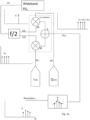
- FIG 2a shows an IQ modulator setup based on the discussion related to figures 1e and 1h .
- the illustrated embodiment includes a PLL, preferably capable of covering a wide frequency range, an IQ modulator and two DAC's (Digital to Analog Converter) I DAC , Q DAC .
- the signal from the PLL is divided as illustrated in figure 1h in order to produce the two LO inputs, LOi, LOq to the IQ modulator.
- the PLL in figure 2a may provide a frequency within a wide range from a few megahertz up to several Gigahertz, but the frequency cannot change instantly (typically 1 ⁇ s to settle on a new frequency) and the PLL cannot be used to generate multi-tunes.
- the DAC's are generating a lower frequency signal typically from a few hundred kilohertz up to some 10's of Megahertz (limited by the clock frequency of the ADC's in the IQ demodulator, for example 30 MHz).
- a DDS D irect D igital S ynthesis
- a DDS is also considered to be a DAC (a DDS is a DAC with a dedicated control system).
- the output from the DAC's is illustrated as a signal with number of distinct frequency components f RF at a relatively low frequency compared to the PLL signal.
- the IQ modulator needs both the I and Q version of both the signal from the PLL(LO I LO Q ) and from the DAC's (RF I , RF Q ) and provides signal IQ OUT at a corresponding number of output frequencies with known amplitudes that are applied to the microwave sensor, illustrated as a resonator.
- This is illustrated with the f R , a multitone signal at a high frequency.
- This process is usually referred to as an IQ modulation or a S ingle S ide B and mixing (SSB).
- the PLL when tracking a resonator, the PLL is in this embodiment is aiming to find the resonance frequency ⁇ R of the resonator in a certain range by applying signals at chosen frequencies within the range expected to have a resonance peak.
- the information can be used to determine the frequency of the resonance peak without sweeping over the frequency range.
- This may be used to provide an instant measurement to determine the peak and possibly the Q-factor of the resonance ⁇ R by means of curve fitting the information based on the amplitudes of the multiple frequency points f R illustrated in figure 2a as the Resonator out .
- four frequencies are used but other numbers may be used depending on the required accuracy in the calculated resonance frequency and the characteristics of the DACs and receiver system.
- a fast sweeping over a limited frequency range may be performed using the DAC's for providing the varying frequency, while the slower PLL may provide a constant base frequency. This way it is possible to make sure that one of the frequencies moves into the resonance frequency, thus being detected at the receiver means.
- the f/2 part in the illustrated example is used to divide the frequency in order to generate two signals with identical frequency and these signals needs to be exactly 90 degrees phase shifted to suppress the mirror signal (if we are generating f1+ f2 the mirror signal has fl-f2). If the LO signal goes to 2 different circuits, one divides the frequency in 2 (a D flip-flop for instance), the other inverts the signal and then divides the frequency, then the result is 2 signals 90 degrees phase shifted, as is described in figure 1h .
- the alternative is an RC network as illustrated in figure 1g , but this is less precise.
- DDS Digital Direct Synthesis
- FIG 3a an embodiment is shown using the IQ modulator for rapid scanning of a large frequency range.
- a wide band PLL is generally slow, after a frequency shift the PLL can take typically 1 ⁇ s to stabilize in the new frequency setting. Rapid scanning of a wide frequency range with high resolution is therefore a slow process with a PLL.
- a DAC on the other hand (or a DDS which is practically the same) changes frequency instantaneously and this allows for a rapid, high resolution scan.
- the disadvantage of using a DAC is that the clock frequency needs to be many times higher than the output frequency in order to avoid dominant spurious frequencies. This limits the max frequency in these components and makes it hard to use them in the GHz range.
- the PLL produces a high frequency signal, (GHz range) and this is added with the lower frequency signal from the 2 DAC's (MHz range).
- the 2 DAC's produces identical signals with a 90 degrees phase between them (I and Q), this allows for the frequency of the signal from the PLL (f LO ) and the frequency of the signals from the DAC's (f RF ) to be added producing a signal with a frequency equal to the sum of frequency of f RF and f LO .
- the DAC's to scan between 0 and the max DAC frequency f RF max we can perform a rapid scan around the PLL frequency f LO . (changing the order of the I and Q signal from the DAC will cause the frequency to be subtracted instead of added to the PLL frequency). After this operation we will have scanned (rapidly with high resolution) a band around the PLL frequency. To continue the scanning the PLL frequency may be increases with 2 X f RF max .
- a scan is performed from f LO1 -f RFmax to f LO1 +f RFmax by changing the frequency from the DAC but without changing the PLL frequency (f LO1 ), after the scan from f LO1 -f RFmax to f LO1 +f RFmax has been completed the PLL frequency is increased with 2 X f RF max to f LO2 , then the band from f LO2 -f RFmax to f LO2 +f RFmax is scanned so that all intermediate frequencies between f LO1 -f RFmax and f LO2 +f RFmax are covered.
- the advantages with this system are as follows. Few and large steps may be provided by the PLL, and therefore slow settling of the PLL will have less impact on the scanning speed.
- the DAC's (or DDS) may be operated with a high ratio between the clock signal and the RF signal, securing low spurious levels.
- the PLL signal can be used in the demodulator ensuring that there is a frequency difference between the signal used for measurement and the reference signal this will help avoiding leakage.
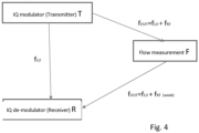
- FIG 4 an implementation of the system is illustrated.
- An example of an IQ de-modulator is illustrated in figure 2b .
- Figure 2a shows a IQ modulator and a resonator
- figure 2b illustrates how the signals coming out of the resonator can be demodulated.
- the IQ modulator up converts the signals to the frequency needed to analyze the resonator, the IQ demodulator down converts the signals to a frequency that within the range of an ADC.
- the I and Q ADC's provides information containing the phase and gain of the frequencies in the signal to a processing unit that can extract this.
- the IQ demodulator also receives the LO signal as a reference from the IQ modulator. As the frequency of the attenuated output signal from the resonator is different from the reference signal leakage between the reference and measuring signals is avoided.
- the invention relates to a measuring system for measuring dielectric properties of a multiphase fluid flow in a pipe.
- the system including a microwave signal generator connected to the multiphase fluid flow for transmitting signals within a predetermined frequency range into said flow through an antenna or similar.
- the signal receiver may include an antenna or similar and is adapted to receive signals within said range from said flow. It also includes analyzing means for calculating the dielectric properties based on the transmitted and received signals.
- microwave range in this case is meant in a broad sense covering the frequency range in or close to the usual definition, as ranges needed for measuring the dielectric characteristics may vary.
- the phrase multiphase fluid may also include wet gas.
- the signal generator unit used according to the invention for generating high frequency signals for a flow meter including a high frequency oscillator such as a Phase Locked Loop (PLL) oscillator generating a first, high frequency signal f LO , the output of the oscillator being connected to the first I and Q inputs of an IQ modulator.
- the system also comprises a low frequency oscillators constituted by a frequency synthesizer adapted to generating signals in several frequencies sequentially of simultaneously within a chosen frequency range f RF , preferably within a short time window so as to sample a measurement in the frequency range within the same flow volume, the duration of the time window depending on the known flow velocity.
- the output signal frequency f RF of the frequency synthesizer is significantly lower than the high frequency signal f LO , each being coupled the I and Q modulator inputs of the IQ modulator.
- the IQ-modulator thus generates output signals constituted by the mix of the input signals, i.e. a sum or difference between the high frequency signals f LO and the low frequency signal f RF at the modulator input, wherein the output range of the IQ modulator is defined by a range above and below the frequency of the oscillator.
- the system according to the invention may therefore provide a rapid frequency scan over a predetermined frequency range where the speed of the scan is driven by the frequency synthesizer and the carrier frequency is given by the oscillator.
- the scanning may alternatively be provided in two frequency ranges simultaneously as the frequency synthesizer may be capable of operating at more than one frequency at the same time. Also it is possible to extend the scanning range by changing the first, oscillator frequency
- the pipe containing the flow may constitute or include a resonator within the frequency range.
- frequency synthesizer may be adapted to emit signals at at least three fixed frequencies having known amplitudes, the receiver means being adapted to analyze the amplitudes of the received signal at each frequency and finding resonance frequency of the resonator by interpolating the amplitude curve between said frequencies.
- the synthesisor may be adapted to emit a rapid frequency scan having known amplitude and the analyzing means may analyse the signal so as to find resonance frequency. I both cases the Q-factor may also be calculated.
- the generator When used in a microwave resonator measuring system the generator is adapted to emit the output signal into a resonator for finding the resonance frequency of the resonator.
- the output of said IQ modulator may include at least four different frequencies.
- the system also comprising receiver means for measuring the amplitude of the signals at said output frequencies and analyzing means for calculating the resonance frequency and preferably also the Q factor based on the amplitude and frequencies of the received signals.
- the IQ modulator output signal including a signal having a varying frequency
- the system including a receiver means and an analyzing means for analyzing the amplitudes of the received signal and finding the resonance frequency and preferably also the Q-factor of the resonator.
- the system according to the invention may also be adapted to emit the output of the signal generator into an antenna in a transmission sensor system, measuring the received signal at another antenna, the IQ modulator output signal including a signal having a varying frequency, the system including a receiver means and an analyzing means for analyzing e.g. the phase shift and attenuation between the two antennas.
- the properties of the medium between the antennas can thereby be measured over a broad frequency range within a very short time window.
Landscapes
- Physics & Mathematics (AREA)
- General Physics & Mathematics (AREA)
- Electromagnetism (AREA)
- Biochemistry (AREA)
- Chemical & Material Sciences (AREA)
- Analytical Chemistry (AREA)
- Life Sciences & Earth Sciences (AREA)
- General Health & Medical Sciences (AREA)
- Health & Medical Sciences (AREA)
- Immunology (AREA)
- Pathology (AREA)
- Fluid Mechanics (AREA)
- Radar Systems Or Details Thereof (AREA)
- Measuring Volume Flow (AREA)
- Measurement Of Resistance Or Impedance (AREA)
Description
- The present invention relates to a measuring system for measuring dielectric properties of a multiphase fluid flow in a pipe. The system includes a microwave signal generator for transmitting signals within a predetermined frequency range into said flow and a signal receiver adapted to receive signals from said flow and analyzing means for calculating the dielectric properties.
- There are many types of microwave sensors in use in meters for various kinds of applications. In a meter there is always an electronics module connected to the sensor for measuring the properties of the sensor. The present invention relates to the use of resonator sensors within or close to the microwave range. The use of microwave resonators for measuring fluid characteristics in flow meters is well known in the oil and gas industry, for example as discussed in
WO2014/122093 andWO2016/169847 providing salinity measurements in a fluid flow. - As an example a resonator sensor displays a resonance peak, when the insertion loss is measured. The peak has two main properties, which are the primary measurement results, the resonant frequency and the Q-factor, i.e. at which frequency the peak appears and how wide or sharp it is. The electronics needs to be able to find the peak within a given frequency range, which might be quite broad, e.g. an octave or more. In on-line applications the peak might in addition change position and shape quite fast. Then the measurement must be performed so fast that it will in practice represent an instantaneous snapshot of the peak. It is therefore an object of the present invention to provide a sufficiently fast measurement. This is obtained by utilizing a system as described in the accompanying claims.
- The most accurate method of measuring a resonance peak is to sample the insertion loss at a number of frequencies, and perform a curve-fit to find the resonant frequency and Q-factor. But if the frequencies are sampled one by one, the movement of the peak during the sampling process creates an error especially in the Q-factor. The sampling process must be fast compared to the dynamics in the resonance peak. Another alternative is to use a multi-tone signal and sample all frequencies simultaneously, as enabled by one embodiment of this invention.
- Another type of microwave sensor is a transmission sensor, see for example "Measurement Of Multiphase Flow Water Fraction And Water-cut" by Cheng-gang Xie in American Institute of Physics Conference Proceedings 014, 232 (2007). Then a signal is transmitted from one small antenna, often called a probe, to another one. On the path the signal passes through the medium to be measured and both the phase shift and the attenuation of the signal are affected by the properties of the medium. Also in this case the properties to be measured may vary fast in on-line applications. In addition, it is often of interest to measure at several, often widely separated, frequencies to gather information on frequency-dependent properties. The phase shift and/or the attenuation may therefore be measured at more than one frequency. Also in this case it may be an advantage to sample all the measurement frequencies simultaneously, or within a very short time interval, to capture data at all the frequencies corresponding to the same measurement situation. E.g. if the sensor is used for measuring a flow of oil, water and gas in a pipe, and the flow moves so fast that while the measurement at one frequency is performed when a gas slug passes the sensor, the measurement at another frequency is performed when there is substantially more liquid at the sensor, the two measurements correspond to different situations and are not directly comparable. In such cases averaging over a much longer time is needed to get useful results. If all the measurement frequencies can be sampled simultaneously, or almost simultaneously, as enabled by one embodiment of the invention, this improves the quality of the results, and shortens the time to reach a high accuracy for the measured and derived properties, which may be e.g. the salinity of the water component, the GVF (Gas Void Fraction), or the water to oil ratio in a flow of oil, water and gas.
- Therefore one aspect of the present invention is aimed at detecting the dielectric properties of a flow by using an IQ converter to combine a high frequency range signal from a high frequency generator such as a PLL with an easy to manipulate lower frequency signal from a frequency synthesizer such as a DAC (or DDS) or similar electronic circuit for generating any of a range of frequencies from a single fixed timebase or oscillator, to generate an easy to manipulate, high frequency range signal. The high frequency signal is coming from the PLL (up to several GHz for the use in multiphase flow meters) but as it is difficult to manipulate this signal a lower frequency signal from a DAC is provided manipulating the higher frequency signal using a IQ modulator.
- The invention will be described more in detail below with reference to the accompanying drawings illustrating the invention by way of examples.
- Figure 1a-h
- illustrates the details of IQ-modulators used according to the invention.
- Figure 2a
- illustrates a first embodiment of the invention.
- Figure 2b
- illustrates an example of an IQ de-modulator
- Figure 3a, b
- illustrates and alternative embodiment of the invention.
- Figure 4
- Illustrates a measuring system including the resonator to be monitored.
- As illustrated in
figures 1a-h an IQ modulator is based on mixing signals.Figure 1a shows a standard frequency multiplier M where two sinus signals I, LOi mixed together will form two new signals I·LOi with respectively the sum of and the difference between the two signals given by:
- In
figure 1b the amplitude vs frequency is illustrated and as can be seen in the spectrum the sum of the frequencies, ω1+ω2, has negative amplitude while the difference, ω1-ω2, has a positive amplitude. - If both signals I and LOi are shifted 90 degrees (sin + 90 degrees is cos), it changes to the situation as is shown in
figures 1c and 1d , where Q and LOq are mixed shifting the sum of the frequencies, ω1+ω2, to be positive. Thus as illustrated infigure 1d .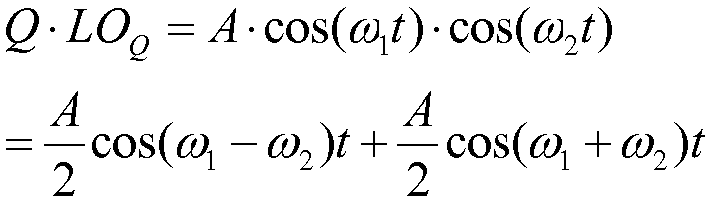
- Since the goal of an IQ modulator is to mix two signals and achieve a signal with a single frequency, the above circuits are combined and a summing device S is added. Both multipliers M and the summer S are basic electronic devices that will not be described here.
-
Figure 1e illustrates a basic sketch for a mixer where the I and Q signals are mixed with LOi and LOq signals, respectively, and the outputs from these mixers are added to provide the sum Q·LOq + I· LOi . The result of this operation may be expressed as
- And can be seen both vector representation in
figure 1f . One of the frequency components is cancelled and the output signal consist of a single frequency ω1-ω2 equal to the difference between the frequencies of the input signals. - This principle is widely used in for instance communication systems, in most systems the I and Q signals are low frequency signals and the LOi and LOq are at a much higher frequency. Also the I and Q signals are complex signals (multiphase and multi frequency) and the LOi and LOq are single frequency carrier signals. If the I and Q have several frequencies, each of the frequencies needs to be shifted 90 degrees. Since the I and Q signals in most applications are complex signals with different phases and frequencies they are generated with DAC's combined with a processing unit (for instance a DSP, Digital Signal Processor). Provided that the DAC's are synchronized (using a single clock) a processor can calculate both the I signal and the corresponding 90 degree shifted Q signal for all the different frequencies in the I signal.
- The generation of the LOi and LOq signals (to be mixed with the I and Q signals respectively) from one LO signal may be performed in different ways, where
figure 1g illustrates the use of an RC filter. If the two R and C's are matched the two signal will have exactly 90 degrees phase difference, the amplitude will however differ which can be restored by running both the LOi and LOq through a comparator and generate a square wave with a set amplitude. -
Figure 1h illustrates an alternative way to generating the LOi and LOq signals using a frequency divider. Starting with a frequency twice the desired frequency f and inverting it will result in a 90 degrees phase shift when both signal are used to trigger a frequency divider. In most applications the starting point is a differential LO signal and two identical frequency dividers, cross connecting the positive and negative part of the LO signal on the two frequency dividers enables a precise 90 degree phase shift. -
Figure 2a shows an IQ modulator setup based on the discussion related tofigures 1e and1h . The illustrated embodiment includes a PLL, preferably capable of covering a wide frequency range, an IQ modulator and two DAC's (Digital to Analog Converter) IDAC, QDAC. In the shown embodiment the signal from the PLL is divided as illustrated infigure 1h in order to produce the two LO inputs, LOi, LOq to the IQ modulator. - The PLL in
figure 2a may provide a frequency within a wide range from a few megahertz up to several Gigahertz, but the frequency cannot change instantly (typically 1 µs to settle on a new frequency) and the PLL cannot be used to generate multi-tunes. The DAC's, however, are generating a lower frequency signal typically from a few hundred kilohertz up to some 10's of Megahertz (limited by the clock frequency of the ADC's in the IQ demodulator, for example 30 MHz). - The advantage of using the two DAC's is that they can generate several tunes fRF at the same time and even white noise if needed, provided that the DAC's are clocked by a frequency much higher than the frequency of the output signal, for example 300 MHz. Note that a DDS (Direct Digital Synthesis) is also considered to be a DAC (a DDS is a DAC with a dedicated control system).
- In
figure 2a the output from the DAC's is illustrated as a signal with number of distinct frequency components fRF at a relatively low frequency compared to the PLL signal. The IQ modulator needs both the I and Q version of both the signal from the PLL(LOI LOQ) and from the DAC's (RFI, RFQ) and provides signal IQOUT at a corresponding number of output frequencies with known amplitudes that are applied to the microwave sensor, illustrated as a resonator. This is illustrated with the fR, a multitone signal at a high frequency. This process is usually referred to as an IQ modulation or a Single Side Band mixing (SSB). - According to the invention, when tracking a resonator, the PLL is in this embodiment is aiming to find the resonance frequency ωR of the resonator in a certain range by applying signals at chosen frequencies within the range expected to have a resonance peak. Using an IQ modulator generating the signals and then measuring the amplitude and the phase of the signals from the resonator the information can be used to determine the frequency of the resonance peak without sweeping over the frequency range.
- This may be used to provide an instant measurement to determine the peak and possibly the Q-factor of the resonance ωR by means of curve fitting the information based on the amplitudes of the multiple frequency points fR illustrated in
figure 2a as the Resonatorout. In the drawing four frequencies are used but other numbers may be used depending on the required accuracy in the calculated resonance frequency and the characteristics of the DACs and receiver system. - As an alternative to the plurality of fixed frequencies a fast sweeping over a limited frequency range (up to a few MHz) may be performed using the DAC's for providing the varying frequency, while the slower PLL may provide a constant base frequency. This way it is possible to make sure that one of the frequencies moves into the resonance frequency, thus being detected at the receiver means.
- Using the limited frequency sweep the responsiveness of the system may be increased, but will require an increase in the processing power and advantageously increased amplification of the measured signals since:

- There are 4 different frequencies in
figure 2a , in reality it is also possible to use more, such as 20, 100 or even white noise, depending on the device being measured. Depending on how well known the shape of the resonance peak is it may also be possible to use three frequencies. - The f/2 part in the illustrated example is used to divide the frequency in order to generate two signals with identical frequency and these signals needs to be exactly 90 degrees phase shifted to suppress the mirror signal (if we are generating f1+ f2 the mirror signal has fl-f2). If the LO signal goes to 2 different circuits, one divides the frequency in 2 (a D flip-flop for instance), the other inverts the signal and then divides the frequency, then the result is 2 signals 90 degrees phase shifted, as is described in
figure 1h . The alternative is an RC network as illustrated infigure 1g , but this is less precise. - As an alternative to DAC's a Digital Direct Synthesis (DDS) with I and Q output exists, being able to be programmed to produce frequency patterns that could be used directly.
- In
figure 3a an embodiment is shown using the IQ modulator for rapid scanning of a large frequency range. A wide band PLL is generally slow, after a frequency shift the PLL can take typically 1 µs to stabilize in the new frequency setting. Rapid scanning of a wide frequency range with high resolution is therefore a slow process with a PLL. A DAC on the other hand (or a DDS which is practically the same) changes frequency instantaneously and this allows for a rapid, high resolution scan. The disadvantage of using a DAC is that the clock frequency needs to be many times higher than the output frequency in order to avoid dominant spurious frequencies. This limits the max frequency in these components and makes it hard to use them in the GHz range. - This embodiment of the invention allows for both rapid, high resolution scanning and high frequency output signals with low spurious levels. The PLL produces a high frequency signal, (GHz range) and this is added with the lower frequency signal from the 2 DAC's (MHz range). The 2 DAC's produces identical signals with a 90 degrees phase between them (I and Q), this allows for the frequency of the signal from the PLL (fLO) and the frequency of the signals from the DAC's (fRF) to be added producing a signal with a frequency equal to the sum of frequency of fRF and fLO.
- By using the DAC's to scan between 0 and the max DAC frequency fRF max we can perform a rapid scan around the PLL frequency fLO. (changing the order of the I and Q signal from the DAC will cause the frequency to be subtracted instead of added to the PLL frequency). After this operation we will have scanned (rapidly with high resolution) a band around the PLL frequency. To continue the scanning the PLL frequency may be increases with 2 X fRF max. As illustrated in
figure 3b a scan is performed from fLO1-fRFmax to fLO1+fRFmax by changing the frequency from the DAC but without changing the PLL frequency (fLO1), after the scan from fLO1-fRFmax to fLO1+fRFmax has been completed the PLL frequency is increased with 2 X fRF max to fLO2, then the band from fLO2-fRFmax to fLO2+fRFmax is scanned so that all intermediate frequencies between fLO1-fRFmax and fLO2+fRFmax are covered. - The advantages with this system are as follows. Few and large steps may be provided by the PLL, and therefore slow settling of the PLL will have less impact on the scanning speed. The DAC's (or DDS) may be operated with a high ratio between the clock signal and the RF signal, securing low spurious levels. The PLL signal can be used in the demodulator ensuring that there is a frequency difference between the signal used for measurement and the reference signal this will help avoiding leakage.
- In
figure 4 an implementation of the system is illustrated. The output from the IQ modulator fOUT=fLO+fRF is transmitted to the resonator in the flow measuring system, e.g. of the types discussed inWO2014/122093 andWO2016/169847 . The output from the resonator fOUT=fLO+fRF(WEAK) is transmitted to an IQ demodulator of any per se known type An example of an IQ de-modulator is illustrated infigure 2b .Figure 2a shows a IQ modulator and a resonator,figure 2b illustrates how the signals coming out of the resonator can be demodulated. The IQ modulator up converts the signals to the frequency needed to analyze the resonator, the IQ demodulator down converts the signals to a frequency that within the range of an ADC. The I and Q ADC's provides information containing the phase and gain of the frequencies in the signal to a processing unit that can extract this. The IQ demodulator also receives the LO signal as a reference from the IQ modulator. As the frequency of the attenuated output signal from the resonator is different from the reference signal leakage between the reference and measuring signals is avoided. - To summarize the invention relates to a measuring system for measuring dielectric properties of a multiphase fluid flow in a pipe. The system including a microwave signal generator connected to the multiphase fluid flow for transmitting signals within a predetermined frequency range into said flow through an antenna or similar. In a similar way the signal receiver may include an antenna or similar and is adapted to receive signals within said range from said flow. It also includes analyzing means for calculating the dielectric properties based on the transmitted and received signals. It should be noted that the "microwave range" in this case is meant in a broad sense covering the frequency range in or close to the usual definition, as ranges needed for measuring the dielectric characteristics may vary. Also, the phrase multiphase fluid may also include wet gas.
- The signal generator unit used according to the invention for generating high frequency signals for a flow meter including a high frequency oscillator such as a Phase Locked Loop (PLL) oscillator generating a first, high frequency signal fLO, the output of the oscillator being connected to the first I and Q inputs of an IQ modulator. The system also comprises a low frequency oscillators constituted by a frequency synthesizer adapted to generating signals in several frequencies sequentially of simultaneously within a chosen frequency range fRF, preferably within a short time window so as to sample a measurement in the frequency range within the same flow volume, the duration of the time window depending on the known flow velocity. The output signal frequency fRF of the frequency synthesizer is significantly lower than the high frequency signal fLO, each being coupled the I and Q modulator inputs of the IQ modulator. The IQ-modulator thus generates output signals constituted by the mix of the input signals, i.e. a sum or difference between the high frequency signals fLO and the low frequency signal fRF at the modulator input, wherein the output range of the IQ modulator is defined by a range above and below the frequency of the oscillator.
- The system according to the invention may therefore provide a rapid frequency scan over a predetermined frequency range where the speed of the scan is driven by the frequency synthesizer and the carrier frequency is given by the oscillator. The scanning may alternatively be provided in two frequency ranges simultaneously as the frequency synthesizer may be capable of operating at more than one frequency at the same time.. Also it is possible to extend the scanning range by changing the first, oscillator frequency
- The pipe containing the flow may constitute or include a resonator within the frequency range. As an example frequency synthesizer may be adapted to emit signals at at least three fixed frequencies having known amplitudes, the receiver means being adapted to analyze the amplitudes of the received signal at each frequency and finding resonance frequency of the resonator by interpolating the amplitude curve between said frequencies. Alternatively the synthesisor may be adapted to emit a rapid frequency scan having known amplitude and the analyzing means may analyse the signal so as to find resonance frequency. I both cases the Q-factor may also be calculated.
- When used in a microwave resonator measuring system the generator is adapted to emit the output signal into a resonator for finding the resonance frequency of the resonator. In a preferred embodiment the output of said IQ modulator may include at least four different frequencies. The system also comprising receiver means for measuring the amplitude of the signals at said output frequencies and analyzing means for calculating the resonance frequency and preferably also the Q factor based on the amplitude and frequencies of the received signals.
- Alternatively, the IQ modulator output signal including a signal having a varying frequency, the system including a receiver means and an analyzing means for analyzing the amplitudes of the received signal and finding the resonance frequency and preferably also the Q-factor of the resonator.
- The system according to the invention may also be adapted to emit the output of the signal generator into an antenna in a transmission sensor system, measuring the received signal at another antenna, the IQ modulator output signal including a signal having a varying frequency, the system including a receiver means and an analyzing means for analyzing e.g. the phase shift and attenuation between the two antennas. The properties of the medium between the antennas can thereby be measured over a broad frequency range within a very short time window.
Claims (10)
- Measuring system for measuring dielectric properties of a multiphase fluid flow in a pipe, the system including a microwave signal generator connected to the multiphase fluid flow for transmitting signals FOUT within a predetermined frequency range into said flow by applying signals FOUT to a microwave sensor constituted by a resonator, the resonator being expected to have a resonance peak within said frequency range , a signal receiver adapted to receive signals within said range from said flow, and analyzing means for calculating the dielectric properties based on the transmitted and received signals, wherein the signal generator includes: an IQ modulator being coupled to a high frequency oscillator and a low frequency synthesizer,wherein the high frequency oscillator is adapted to generate a high frequency signal fLO, in a range from a few MHz to several GHz;the low frequency synthesizer is adapted to generate signals fRF at a number of frequencies within a chosen frequency range lower that the high frequency signal, the chosen frequency being from a few hundred kHz up to some 10's of MHz,said IQ-modulator being adapted to generate an output signal IQOUT constituted by the combination of said signals from the oscillator and the synthesizer, the predetermined frequencies of the oscillator and the synthesizer being chosen based on the required output frequency range for the IQ-modulator,the signal transmitted from the IQ modulator into the resonator thus being FOUT = fLO + fRF, andwherein the receiver includes an IQ demodulator receiving the signal (fLO + fRF (weak)) from the resonator , the IQ demodulator also being connected to the IQ modulator for receiving said high frequency signal fLO, the demodulator thus converting the signal to a frequency in the range of an ADC so as to provide I and Q signals to the analyzing means configured to extract said dielectric properties of a multiphase fluid based on an analysis of the resonance frequency of the resonance peak in the received signal.
- System according to claim 1, wherein the frequency synthesizer simultaneously emits at least two different frequency signals, the output of the IQ modulator thus being constituted by a mix of said high frequency signal and said signals from the low frequency synthesizer.
- System according to claim 1, wherein the frequency synthesizer emits a sequence of different frequencies within said range.
- System according to claim 3, wherein said sequence constitutes a frequency scan over a predetermined frequency range.
- System according to claim 1, wherein said frequency synthesizer is a DAC adapted to control the output frequency and amplitude.
- System according to claim 1, wherein said pipe constitutes a resonator in said frequency range, where said frequency synthesizer is adapted to emit signals at at least three fixed frequencies having known amplitudes, the receiver means being adapted to analyze the amplitudes of the received signal at each frequency and finding resonance frequency of the resonator by interpolating the amplitude curve between said frequencies , the analyzing means being adapted to calculate the dielectric properties on this basis..
- System according to claim 1, wherein said pipe constitutes a resonator in said frequency range, where said frequency synthesizer is adapted to emit a frequency scan having known amplitude, the receiver means being adapted to analyze the received signal so as to find resonance frequency of the resonator, the analyzing means being adapted to calculate the dielectric properties on this basis..
- System according to claim 6 or 7, wherein the Q-factor of the resonance peak at said resonance frequency is calculated.
- System according to claim 7, wherein the oscillator is adapted to change first frequency, thus allowing to change the scanning range of the signal generator.
- System according to claim 1, wherein the receiver means is adapted to calculate the transmission time and attenuation of the transmitted signal through the flow, the analyzing means being adapted to calculate the dielectric properties on this basis.
Applications Claiming Priority (2)
| Application Number | Priority Date | Filing Date | Title |
|---|---|---|---|
| NO20170503A NO349134B1 (en) | 2017-03-28 | 2017-03-28 | Flow measuring system |
| PCT/EP2018/057639 WO2018178011A1 (en) | 2017-03-28 | 2018-03-26 | Flow measuring system |
Publications (3)
| Publication Number | Publication Date |
|---|---|
| EP3602018A1 EP3602018A1 (en) | 2020-02-05 |
| EP3602018C0 EP3602018C0 (en) | 2025-04-23 |
| EP3602018B1 true EP3602018B1 (en) | 2025-04-23 |
Family
ID=61800537
Family Applications (1)
| Application Number | Title | Priority Date | Filing Date |
|---|---|---|---|
| EP18713651.0A Active EP3602018B1 (en) | 2017-03-28 | 2018-03-26 | Flow measuring system |
Country Status (5)
| Country | Link |
|---|---|
| US (1) | US11415446B2 (en) |
| EP (1) | EP3602018B1 (en) |
| CN (1) | CN110476057B (en) |
| NO (1) | NO349134B1 (en) |
| WO (1) | WO2018178011A1 (en) |
Families Citing this family (1)
| Publication number | Priority date | Publication date | Assignee | Title |
|---|---|---|---|---|
| US12276164B2 (en) | 2020-03-30 | 2025-04-15 | Schlumberger Technology Corporation | Inertia damping systems and methods |
Citations (2)
| Publication number | Priority date | Publication date | Assignee | Title |
|---|---|---|---|---|
| EP0988513A1 (en) * | 1997-07-04 | 2000-03-29 | Valmet Automation Inc. | Method of measuring flow, and flow meter |
| US20130009646A1 (en) * | 2005-02-22 | 2013-01-10 | Matthieu Simon | Electromagnetic Probe |
Family Cites Families (43)
| Publication number | Priority date | Publication date | Assignee | Title |
|---|---|---|---|---|
| US4745617A (en) | 1987-03-27 | 1988-05-17 | Hughes Aircraft Company | Ideal distributed Bragg reflectors and resonators |
| JPH079398B2 (en) * | 1987-12-12 | 1995-02-01 | 株式会社堀場製作所 | Fluid analysis device by multi-fluid modulation method |
| FR2722293B1 (en) * | 1994-07-08 | 2000-04-07 | Inst Francais Du Petrole | POLYPHASTIC FLOWMETER |
| US5608665A (en) | 1995-10-03 | 1997-03-04 | Wyszynski; Adam S. | Self-tuned, continuous-time active filter |
| US5841288A (en) * | 1996-02-12 | 1998-11-24 | Microwave Imaging System Technologies, Inc. | Two-dimensional microwave imaging apparatus and methods |
| US6182504B1 (en) | 1997-11-03 | 2001-02-06 | Roxar, Inc. | Emulsion composition monitor |
| NO308922B1 (en) | 1998-06-03 | 2000-11-13 | Multi Fluid Asa | Meters, in particular for continuous measurement of the mixing ratio between two fluids flowing in pipes, e.g. water content of oil; and the procedure for carrying out such a measurement |
| JP2002005971A (en) * | 2000-06-26 | 2002-01-09 | Tatsuo Miyagawa | Physical property discriminating device |
| US6351409B1 (en) | 2001-01-04 | 2002-02-26 | Motorola, Inc. | MRAM write apparatus and method |
| GB2376074B (en) | 2001-05-30 | 2004-02-04 | Schlumberger Holdings | Methods and apparatus for estimating on-line water conductivity of multiphase mixtures |
| RU2192646C1 (en) * | 2001-06-13 | 2002-11-10 | Тамбовский государственный технический университет | Device determining dielectric permittivity of liquid |
| PL348996A1 (en) | 2001-08-01 | 2003-02-10 | B Sp Z Oo Ab | Method of and apparatus for monitoring the parameters of aqueous phase in water-and-oil emulsions |
| NO315584B1 (en) | 2001-10-19 | 2003-09-22 | Roxar Flow Measurement As | Compact flow templates |
| US6696684B2 (en) | 2001-12-28 | 2004-02-24 | Schlumberger Technology Corporation | Formation evaluation through azimuthal tool-path identification |
| NO323247B1 (en) | 2003-12-09 | 2007-02-12 | Multi Phase Meters As | Method and flow meter for determining the flow rates of a multiphase mixture |
| US7078913B1 (en) * | 2003-12-31 | 2006-07-18 | The United States Of America As Represented By The Secretary Of Agriculture | Multipath resistant microwave moisture sensor |
| NO320172B1 (en) | 2004-02-27 | 2005-11-07 | Roxar Flow Measurement As | Flow templates and methods for painting individual quantities of gas, hydrocarbon liquid and water in a fluid mixture |
| ATE443855T1 (en) | 2004-07-13 | 2009-10-15 | Schlumberger Technology Bv | DETECTOR FOR DIFFERENTIATING PHASES IN A MULTI-PHASE LIQUID MIXTURE |
| NO323244B1 (en) | 2004-08-20 | 2007-02-12 | Multi Phase Meters As | Method and equipment for measuring composition and salinity in a multiphase flow |
| EP1645863B1 (en) | 2004-10-07 | 2007-07-04 | Services Petroliers Schlumberger | A sampling apparatus |
| US7524423B2 (en) | 2004-12-10 | 2009-04-28 | Clearwater Systems Corporation | System and method of generating a ringing magnetic pulse for the treatment of flowing liquids |
| NO323451B1 (en) * | 2005-08-11 | 2007-05-14 | Multi Phase Meters As | Method and apparatus for determining conductivity and volume traction of water in a multicomponent mixture |
| GB2430493B (en) * | 2005-09-23 | 2008-04-23 | Schlumberger Holdings | Systems and methods for measuring multiphase flow in a hydrocarbon transporting pipeline |
| GB2432425B (en) | 2005-11-22 | 2008-01-09 | Schlumberger Holdings | Isokinetic sampling method and system for multiphase flow from subterranean wells |
| NO324582B1 (en) | 2006-02-03 | 2007-11-26 | Roxar As | Differential pressure paint device |
| US9116104B2 (en) * | 2006-03-22 | 2015-08-25 | Agar Corporation, Ltd. | Method and apparatus for detecting water in a fluid media |
| NO326977B1 (en) | 2006-05-02 | 2009-03-30 | Multi Phase Meters As | Method and apparatus for measuring the conductivity of the water fraction in a wet gas |
| DE102006052637B4 (en) | 2006-11-08 | 2009-02-26 | Technische Universität Darmstadt | Device and method for determining at least one parameter of a medium |
| NO328801B1 (en) * | 2007-01-12 | 2010-05-18 | Roxar Flow Measurement As | System and method for determining properties during transport of hydrocarbon fluids in a pipeline |
| US8027794B2 (en) | 2008-02-11 | 2011-09-27 | Schlumberger Technology Corporaton | System and method for measuring properties of liquid in multiphase mixtures |
| AU2009252932A1 (en) | 2008-05-27 | 2009-12-03 | Bae Systems Plc | Damage sensors and processing arrangements therefor |
| US20110118990A1 (en) | 2008-05-27 | 2011-05-19 | Jagjit Sidhu | Damage sensors and processing arrangements therefor |
| NO331270B1 (en) | 2009-04-06 | 2011-11-14 | Roxar Flow Measurement As | Method for monitoring a body inserted in a duct, as well as a system including an insert for electromagnetic resonance paints |
| US8322228B2 (en) * | 2009-12-11 | 2012-12-04 | Schlumberger Technology Corporation | Method of measuring flow properties of a multiphase fluid |
| US9927270B2 (en) * | 2011-12-06 | 2018-03-27 | Schlumberger Technology Corporation | Multiphase flowmeter |
| WO2013181173A1 (en) * | 2012-05-30 | 2013-12-05 | General Electric Company | Sensor apparatus for measurement of material properties |
| US9109995B2 (en) * | 2012-10-16 | 2015-08-18 | Kam Controls, Inc. | Method and apparatus for determining the water concentration in a fluid mixture |
| US9856157B2 (en) | 2013-01-31 | 2018-01-02 | Reverse Ionizer Systems, Llc | Devices, systems and methods for treatment of water with electromagnetic fields |
| NO347105B1 (en) | 2013-02-05 | 2023-05-15 | Roxar Flow Measurement As | Conductivity measurement |
| WO2014121928A1 (en) | 2013-02-07 | 2014-08-14 | Giesecke & Devrient Gmbh | Method and device for testing a circuit |
| EP3218700B1 (en) * | 2014-11-10 | 2020-04-15 | General Electric Company | Multi-phase fluid fraction measurement |
| NO342831B1 (en) | 2015-04-23 | 2018-08-13 | Roxar Flow Measurement As | System for measuring characteristics of a fluid flow |
| US20170038311A1 (en) * | 2015-08-03 | 2017-02-09 | William Thomas Conrad | Radio frequency material analysis utilizing phase |
-
2017
- 2017-03-28 NO NO20170503A patent/NO349134B1/en unknown
-
2018
- 2018-03-26 US US16/497,528 patent/US11415446B2/en active Active
- 2018-03-26 EP EP18713651.0A patent/EP3602018B1/en active Active
- 2018-03-26 CN CN201880022420.6A patent/CN110476057B/en active Active
- 2018-03-26 WO PCT/EP2018/057639 patent/WO2018178011A1/en not_active Ceased
Patent Citations (2)
| Publication number | Priority date | Publication date | Assignee | Title |
|---|---|---|---|---|
| EP0988513A1 (en) * | 1997-07-04 | 2000-03-29 | Valmet Automation Inc. | Method of measuring flow, and flow meter |
| US20130009646A1 (en) * | 2005-02-22 | 2013-01-10 | Matthieu Simon | Electromagnetic Probe |
Also Published As
| Publication number | Publication date |
|---|---|
| NO20170503A1 (en) | 2018-10-01 |
| NO349134B1 (en) | 2025-10-13 |
| US11415446B2 (en) | 2022-08-16 |
| EP3602018A1 (en) | 2020-02-05 |
| EP3602018C0 (en) | 2025-04-23 |
| CN110476057B (en) | 2022-06-10 |
| WO2018178011A1 (en) | 2018-10-04 |
| CN110476057A (en) | 2019-11-19 |
| US20200116538A1 (en) | 2020-04-16 |
Similar Documents
| Publication | Publication Date | Title |
|---|---|---|
| CN102325058B (en) | A method for testing group delay of frequency conversion system | |
| US9429528B2 (en) | Determining gas absorption line from separate and alternating RF signals | |
| US10623009B2 (en) | Frequency generator with two voltage controlled oscillators | |
| US20090212997A1 (en) | Method for measuring a distance running time | |
| Tschapek et al. | Phase noise spectral density measurement of broadband frequency-modulated radar signals | |
| CN110383063B (en) | Structure for detecting concrete by means of electromagnetic waves | |
| CN111665404B (en) | Accurate Phase Synchronization Nonlinear Vector Network Analyzer Measurement Method and Device | |
| CN106199187A (en) | A kind of method of testing of multi-tone signal relative phase | |
| US11415446B2 (en) | Flow measuring system | |
| JP3973036B2 (en) | Pulse radar equipment | |
| JP6756491B2 (en) | Methods and Devices for Generating Normalized Phase Spectrum | |
| JP2006017486A (en) | Spectral analysis method and nuclear magnetic resonance apparatus using nuclear magnetic resonance | |
| CN120344872A (en) | Test device for testing a distance sensor operating with electromagnetic waves and frequency divider device for such a test device | |
| US2820898A (en) | Distance measuring equipment utilizing frequency modulation | |
| US20050151956A1 (en) | Apparatus for precise distance measurement | |
| Musch et al. | Measurement of the ramp linearity of extremely linear frequency ramps using a fractional dual loop structure | |
| EP1640734B1 (en) | A method and apparatus for measuring the input frequency response of a digital receiver | |
| RU2362180C2 (en) | Short-range radiolocator with ultra high resolution (versions) | |
| Zajac et al. | Upgrade of the COMPASS tokamak microwave reflectometry system with I/Q modulation and detection | |
| RU2330298C2 (en) | Method for detection of damage point in power transmission and communication lines and device for its implementation | |
| KR101766765B1 (en) | System for Linear Phase shift Type Reflectometer | |
| Anthonys et al. | Jitter measurement in digital signals by using software defined radio technology | |
| JP2004264067A (en) | Pulse radar device and distance detection method thereof | |
| US20080122427A1 (en) | Device and Method for Measuring a Phase Deviation | |
| JP2000046932A (en) | FM-CW radar device |
Legal Events
| Date | Code | Title | Description |
|---|---|---|---|
| STAA | Information on the status of an ep patent application or granted ep patent |
Free format text: STATUS: UNKNOWN |
|
| STAA | Information on the status of an ep patent application or granted ep patent |
Free format text: STATUS: THE INTERNATIONAL PUBLICATION HAS BEEN MADE |
|
| PUAI | Public reference made under article 153(3) epc to a published international application that has entered the european phase |
Free format text: ORIGINAL CODE: 0009012 |
|
| STAA | Information on the status of an ep patent application or granted ep patent |
Free format text: STATUS: REQUEST FOR EXAMINATION WAS MADE |
|
| 17P | Request for examination filed |
Effective date: 20190924 |
|
| AK | Designated contracting states |
Kind code of ref document: A1 Designated state(s): AL AT BE BG CH CY CZ DE DK EE ES FI FR GB GR HR HU IE IS IT LI LT LU LV MC MK MT NL NO PL PT RO RS SE SI SK SM TR |
|
| AX | Request for extension of the european patent |
Extension state: BA ME |
|
| DAV | Request for validation of the european patent (deleted) | ||
| DAX | Request for extension of the european patent (deleted) | ||
| STAA | Information on the status of an ep patent application or granted ep patent |
Free format text: STATUS: EXAMINATION IS IN PROGRESS |
|
| 17Q | First examination report despatched |
Effective date: 20220222 |
|
| GRAP | Despatch of communication of intention to grant a patent |
Free format text: ORIGINAL CODE: EPIDOSNIGR1 |
|
| STAA | Information on the status of an ep patent application or granted ep patent |
Free format text: STATUS: GRANT OF PATENT IS INTENDED |
|
| INTG | Intention to grant announced |
Effective date: 20241223 |
|
| GRAS | Grant fee paid |
Free format text: ORIGINAL CODE: EPIDOSNIGR3 |
|
| GRAA | (expected) grant |
Free format text: ORIGINAL CODE: 0009210 |
|
| STAA | Information on the status of an ep patent application or granted ep patent |
Free format text: STATUS: THE PATENT HAS BEEN GRANTED |
|
| AK | Designated contracting states |
Kind code of ref document: B1 Designated state(s): AL AT BE BG CH CY CZ DE DK EE ES FI FR GB GR HR HU IE IS IT LI LT LU LV MC MK MT NL NO PL PT RO RS SE SI SK SM TR |
|
| REG | Reference to a national code |
Ref country code: GB Ref legal event code: FG4D |
|
| REG | Reference to a national code |
Ref country code: CH Ref legal event code: EP |
|
| REG | Reference to a national code |
Ref country code: DE Ref legal event code: R096 Ref document number: 602018081282 Country of ref document: DE |
|
| REG | Reference to a national code |
Ref country code: IE Ref legal event code: FG4D |
|
| U01 | Request for unitary effect filed |
Effective date: 20250514 |
|
| U07 | Unitary effect registered |
Designated state(s): AT BE BG DE DK EE FI FR IT LT LU LV MT NL PT RO SE SI Effective date: 20250520 |
|
| PG25 | Lapsed in a contracting state [announced via postgrant information from national office to epo] |
Ref country code: ES Free format text: LAPSE BECAUSE OF FAILURE TO SUBMIT A TRANSLATION OF THE DESCRIPTION OR TO PAY THE FEE WITHIN THE PRESCRIBED TIME-LIMIT Effective date: 20250423 |
|
| PG25 | Lapsed in a contracting state [announced via postgrant information from national office to epo] |
Ref country code: NO Free format text: LAPSE BECAUSE OF FAILURE TO SUBMIT A TRANSLATION OF THE DESCRIPTION OR TO PAY THE FEE WITHIN THE PRESCRIBED TIME-LIMIT Effective date: 20250723 Ref country code: GR Free format text: LAPSE BECAUSE OF FAILURE TO SUBMIT A TRANSLATION OF THE DESCRIPTION OR TO PAY THE FEE WITHIN THE PRESCRIBED TIME-LIMIT Effective date: 20250724 |
|
| PG25 | Lapsed in a contracting state [announced via postgrant information from national office to epo] |
Ref country code: PL Free format text: LAPSE BECAUSE OF FAILURE TO SUBMIT A TRANSLATION OF THE DESCRIPTION OR TO PAY THE FEE WITHIN THE PRESCRIBED TIME-LIMIT Effective date: 20250423 |
|
| PG25 | Lapsed in a contracting state [announced via postgrant information from national office to epo] |
Ref country code: HR Free format text: LAPSE BECAUSE OF FAILURE TO SUBMIT A TRANSLATION OF THE DESCRIPTION OR TO PAY THE FEE WITHIN THE PRESCRIBED TIME-LIMIT Effective date: 20250423 |
|
| PG25 | Lapsed in a contracting state [announced via postgrant information from national office to epo] |
Ref country code: RS Free format text: LAPSE BECAUSE OF FAILURE TO SUBMIT A TRANSLATION OF THE DESCRIPTION OR TO PAY THE FEE WITHIN THE PRESCRIBED TIME-LIMIT Effective date: 20250723 |
|
| PG25 | Lapsed in a contracting state [announced via postgrant information from national office to epo] |
Ref country code: IS Free format text: LAPSE BECAUSE OF FAILURE TO SUBMIT A TRANSLATION OF THE DESCRIPTION OR TO PAY THE FEE WITHIN THE PRESCRIBED TIME-LIMIT Effective date: 20250823 |
|
| PG25 | Lapsed in a contracting state [announced via postgrant information from national office to epo] |
Ref country code: SM Free format text: LAPSE BECAUSE OF FAILURE TO SUBMIT A TRANSLATION OF THE DESCRIPTION OR TO PAY THE FEE WITHIN THE PRESCRIBED TIME-LIMIT Effective date: 20250423 |
|
| PG25 | Lapsed in a contracting state [announced via postgrant information from national office to epo] |
Ref country code: CZ Free format text: LAPSE BECAUSE OF FAILURE TO SUBMIT A TRANSLATION OF THE DESCRIPTION OR TO PAY THE FEE WITHIN THE PRESCRIBED TIME-LIMIT Effective date: 20250423 |
|
| PG25 | Lapsed in a contracting state [announced via postgrant information from national office to epo] |
Ref country code: SK Free format text: LAPSE BECAUSE OF FAILURE TO SUBMIT A TRANSLATION OF THE DESCRIPTION OR TO PAY THE FEE WITHIN THE PRESCRIBED TIME-LIMIT Effective date: 20250423 |
|
| PLBE | No opposition filed within time limit |
Free format text: ORIGINAL CODE: 0009261 |
|
| STAA | Information on the status of an ep patent application or granted ep patent |
Free format text: STATUS: NO OPPOSITION FILED WITHIN TIME LIMIT |
|
| REG | Reference to a national code |
Ref country code: CH Ref legal event code: L10 Free format text: ST27 STATUS EVENT CODE: U-0-0-L10-L00 (AS PROVIDED BY THE NATIONAL OFFICE) Effective date: 20260304 |
|
| U20 | Renewal fee for the european patent with unitary effect paid |
Year of fee payment: 9 Effective date: 20260219 |
|
| 26N | No opposition filed |
Effective date: 20260126 |
|
| PGFP | Annual fee paid to national office [announced via postgrant information from national office to epo] |
Ref country code: GB Payment date: 20260219 Year of fee payment: 9 |