EP3601950B1 - Integrated optic wavemeter and method for fiber optic gyroscopes scale factor stabilization - Google Patents
Integrated optic wavemeter and method for fiber optic gyroscopes scale factor stabilization Download PDFInfo
- Publication number
- EP3601950B1 EP3601950B1 EP18716763.0A EP18716763A EP3601950B1 EP 3601950 B1 EP3601950 B1 EP 3601950B1 EP 18716763 A EP18716763 A EP 18716763A EP 3601950 B1 EP3601950 B1 EP 3601950B1
- Authority
- EP
- European Patent Office
- Prior art keywords
- optic
- wavemeter
- signal
- rotation sensor
- processed
- Prior art date
- Legal status (The legal status is an assumption and is not a legal conclusion. Google has not performed a legal analysis and makes no representation as to the accuracy of the status listed.)
- Active
Links
Images


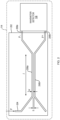




Classifications
-
- G—PHYSICS
- G01—MEASURING; TESTING
- G01C—MEASURING DISTANCES, LEVELS OR BEARINGS; SURVEYING; NAVIGATION; GYROSCOPIC INSTRUMENTS; PHOTOGRAMMETRY OR VIDEOGRAMMETRY
- G01C19/00—Gyroscopes; Turn-sensitive devices using vibrating masses; Turn-sensitive devices without moving masses; Measuring angular rate using gyroscopic effects
- G01C19/58—Turn-sensitive devices without moving masses
- G01C19/64—Gyrometers using the Sagnac effect, i.e. rotation-induced shifts between counter-rotating electromagnetic beams
- G01C19/72—Gyrometers using the Sagnac effect, i.e. rotation-induced shifts between counter-rotating electromagnetic beams with counter-rotating light beams in a passive ring, e.g. fibre laser gyrometers
- G01C19/725—Gyrometers using the Sagnac effect, i.e. rotation-induced shifts between counter-rotating electromagnetic beams with counter-rotating light beams in a passive ring, e.g. fibre laser gyrometers using nxn optical couplers, e.g. 3x3 couplers
-
- G—PHYSICS
- G01—MEASURING; TESTING
- G01B—MEASURING LENGTH, THICKNESS OR SIMILAR LINEAR DIMENSIONS; MEASURING ANGLES; MEASURING AREAS; MEASURING IRREGULARITIES OF SURFACES OR CONTOURS
- G01B9/00—Measuring instruments characterised by the use of optical techniques
- G01B9/02—Interferometers
-
- G—PHYSICS
- G01—MEASURING; TESTING
- G01C—MEASURING DISTANCES, LEVELS OR BEARINGS; SURVEYING; NAVIGATION; GYROSCOPIC INSTRUMENTS; PHOTOGRAMMETRY OR VIDEOGRAMMETRY
- G01C19/00—Gyroscopes; Turn-sensitive devices using vibrating masses; Turn-sensitive devices without moving masses; Measuring angular rate using gyroscopic effects
- G01C19/58—Turn-sensitive devices without moving masses
- G01C19/64—Gyrometers using the Sagnac effect, i.e. rotation-induced shifts between counter-rotating electromagnetic beams
- G01C19/72—Gyrometers using the Sagnac effect, i.e. rotation-induced shifts between counter-rotating electromagnetic beams with counter-rotating light beams in a passive ring, e.g. fibre laser gyrometers
-
- G—PHYSICS
- G01—MEASURING; TESTING
- G01J—MEASUREMENT OF INTENSITY, VELOCITY, SPECTRAL CONTENT, POLARISATION, PHASE OR PULSE CHARACTERISTICS OF INFRARED, VISIBLE OR ULTRAVIOLET LIGHT; COLORIMETRY; RADIATION PYROMETRY
- G01J3/00—Spectrometry; Spectrophotometry; Monochromators; Measuring colours
- G01J3/12—Generating the spectrum; Monochromators
- G01J3/26—Generating the spectrum; Monochromators using multiple reflection, e.g. Fabry-Perot interferometer, variable interference filters
-
- G—PHYSICS
- G01—MEASURING; TESTING
- G01J—MEASUREMENT OF INTENSITY, VELOCITY, SPECTRAL CONTENT, POLARISATION, PHASE OR PULSE CHARACTERISTICS OF INFRARED, VISIBLE OR ULTRAVIOLET LIGHT; COLORIMETRY; RADIATION PYROMETRY
- G01J9/00—Measuring optical phase difference; Determining degree of coherence; Measuring optical wavelength
- G01J9/02—Measuring optical phase difference; Determining degree of coherence; Measuring optical wavelength by interferometric methods
- G01J9/0246—Measuring optical wavelength
-
- H—ELECTRICITY
- H01—ELECTRIC ELEMENTS
- H01S—DEVICES USING THE PROCESS OF LIGHT AMPLIFICATION BY STIMULATED EMISSION OF RADIATION [LASER] TO AMPLIFY OR GENERATE LIGHT; DEVICES USING STIMULATED EMISSION OF ELECTROMAGNETIC RADIATION IN WAVE RANGES OTHER THAN OPTICAL
- H01S5/00—Semiconductor lasers
- H01S5/06—Arrangements for controlling the laser output parameters, e.g. by operating on the active medium
- H01S5/068—Stabilisation of laser output parameters
- H01S5/0683—Stabilisation of laser output parameters by monitoring the optical output parameters
- H01S5/0687—Stabilising the frequency of the laser
-
- G—PHYSICS
- G01—MEASURING; TESTING
- G01J—MEASUREMENT OF INTENSITY, VELOCITY, SPECTRAL CONTENT, POLARISATION, PHASE OR PULSE CHARACTERISTICS OF INFRARED, VISIBLE OR ULTRAVIOLET LIGHT; COLORIMETRY; RADIATION PYROMETRY
- G01J9/00—Measuring optical phase difference; Determining degree of coherence; Measuring optical wavelength
- G01J9/02—Measuring optical phase difference; Determining degree of coherence; Measuring optical wavelength by interferometric methods
- G01J2009/0226—Fibres
- G01J2009/023—Fibres of the integrated optical type
-
- G—PHYSICS
- G02—OPTICS
- G02B—OPTICAL ELEMENTS, SYSTEMS OR APPARATUS
- G02B6/00—Light guides; Structural details of arrangements comprising light guides and other optical elements, e.g. couplings
- G02B6/24—Coupling light guides
- G02B6/26—Optical coupling means
- G02B6/28—Optical coupling means having data bus means, i.e. plural waveguides interconnected and providing an inherently bidirectional system by mixing and splitting signals
- G02B6/2804—Optical coupling means having data bus means, i.e. plural waveguides interconnected and providing an inherently bidirectional system by mixing and splitting signals forming multipart couplers without wavelength selective elements, e.g. "T" couplers, star couplers
- G02B6/2821—Optical coupling means having data bus means, i.e. plural waveguides interconnected and providing an inherently bidirectional system by mixing and splitting signals forming multipart couplers without wavelength selective elements, e.g. "T" couplers, star couplers using lateral coupling between contiguous fibres to split or combine optical signals
Definitions
- a fiber optic gyroscope employs an optic source to generate light, which is introduced into a fiber sensing coil for use in detecting rotation of the fiber sensing coil.
- Advantages of using a broadband optic source include (i) high optic power and (ii) a short coherence length.
- a short coherence length reduces the interference contrast of the various parasitic waves generated in the system by, for example, back-reflection, backscattering, and/or polarization cross-coupling.
- the short coherence length also suppresses the effects of Kerr nonlinearity, which causes optic non-reciprocity and produces rotation measurement error.
- An edge emitting semiconductor diode based on superluminescence, is one type of optic source typically used in FOG devices.
- Such an optic source combines the high power and brightness of laser diodes, with the low coherence of conventional light-emitting diodes. Its emission bandwidth is typically between 15nm and 50nm.
- the light emitted from such a broadband superluminescence diode (referred to herein as "SLD") may then be coupled to a rotation sensing optic system. In the rotation sensing optic system, the light from the SLD is split and used to create counter-propagating light beams which propagate within a fiber optic sensing coil.
- a phase shift between the counter-propagating waves develops as a result of a physical rotation of the fiber optic sensing coil, corresponding to the rotation of the FOG.
- the counter propagating light beams are directed by the first directional coupler to a photodetector, where the intensity of the light beams (resulting from the interference between the two beams) is measured to determine the angular speed of the FOG rotation.
- the angular speed of the FOG rotation is related to the phase information provided by the light in the sensing coil through a term referred to herein as "scale factor.”
- the scale factor describes the sensitivity of the FOG by relating an amount of phase change between the two light beams to a FOG rotation angular speed.
- the scale factor is linearly related to the "effective interferometric wavelength" of the SLD's light, which is a weighted average of the SLD light's spectrum.
- the mechanisms of the filtering can be different, such as a mode field difference between the light source and a PM fiber, a limited bandwidth at a fiber to PIC waveguide connection, a spectral dependence of the split ratio of the directional coupler, or a limited spectral bandwidth of the transmission of a polarizer.
- the optic components may also suffer from the potential wavelength changes with aging and/or environmental conditions. When the light source and the optic circuit are exposed to harsh environments, the changes in the optic spectrum may be accelerated, resulting in a large scale factor error. Different wavelengths in the broadband spectrum of the light source can experience different levels of attenuation due to the aging of the components in the optic circuit of the FOG. Such components may include, but are not limited to, polarizers, couplers, and connection joints between optic fibers and an integrated waveguide. Variations in one or more of these components may shift the effective interferometric wavelength, and thereby change the scale factor. For FOGs being used in applications that require a high degree of accuracy, these variations may create an unacceptable level of error. There is a need for stabilization of the scale factor of a broadband fiber source used in fiber optic gyros, especially when exposed to radiation and other external influences.
- the described embodiments generally relate to fiber optic gyroscope (FOG), and specially described embodiments pertain to the measurement of the effective interferometric wavelength (EIW) of the optic spectrum of a broadband light source of a FOG.
- the described embodiments provide an apparatus based on a photonic integrated circuit (PIC) for the EIW.
- PIC photonic integrated circuit
- the effective interferometric wavelength needs to have an accuracy of 0.083 nm for 830nm and 0.155 nm for 1550nm, which is considerably small in comparison to the 15 ⁇ 50nm spectral bandwidth.
- a FOG responds to rotation with a slightly different scale factor value for different wavelengths in the spectrum of the FOG light source.
- the measurement of the angular speed of rotation is a weighted average of the response of all incremental portions of the FOG light source spectrum.
- the overall scale factor is dependent on not only the mean wavelength but also the shape of the spectrum, such as the spectral symmetricity and the fine spectrum structures.
- the most common fine spectrum structure is spectrum ripples.
- the ripple is a result of a residual cavity oscillation, if the anti-reflection coating is imperfect.
- FIG. 1A shows a typical spectrum of a SLD with its front facet coated with an anti-reflection coating, and with the waveguide at the back end micro-fabricated into an anti-reflection shape.
- SLD temperature, drive current to the SLD, and SLD aging may change characteristics of the ripple.
- the residual cavity oscillation is also responsible for the residual laser structure in the coherence function of the broadband source.
- the scale factor is linearly related to the centroid wavenumber of the FOG broadband light source, when the FOG is operated at or near its most linear phase bias position.
- the wavemeter system and the measurement method of the described embodiments are devised to measure the same effective interferometric wavelength that is used for rotation sensing, as described herein.
- the signal detection and amplification techniques for the wavemeter of the described embodiments may achieve robust measurements, even when the broadband light source experiences ionizing radiation and other harsh environmental conditions.
- aspects of the described embodiments may be utilized in conjunction with a conventional FOG, to produce a "corrected" FOG, which exhibits a more stable scaling factor than that of the conventional FOG alone.
- the invention involves an optic wavemeter for measuring an optic wavelength.
- the optic wavemeter may comprise a first optic waveguide to guide at least a portion of an optic signal, derived from broadband light, for an interaction length, and to produce a first processed optic signal.
- the optic wavemeter may further comprise a second optic waveguide, a segment of which is arranged in close proximity to the first optic waveguide. The segment may extend along an interaction length, such that the second optic waveguide receives a portion of the optic signal from first optic waveguide through evanescent coupling along the interaction length, and produces a second processed optic signal.
- the optic wavemeter may further comprise a wavemeter detector to measure an effective interferometric wavelength of the broadband light, based on the first processed optical signal and second processed optic signal.
- the invention may be a system for stabilizing a scale factor associated with an optic rotation sensor.
- the optic rotation sensor may comprise a light source to emit broadband light, and a rotation sensing optic system to generate an optic signal.
- the optic signal may be derived from the broadband light and generated in response to a rotation of the optic rotation sensor.
- the optic rotation sensor may further include a sensor detection system to produce a rotation measurement signal as a function of the optic signal and rotation of the optic rotation sensor.
- the system may further comprise a wavemeter coupled to the optic rotation sensor.
- the wavemeter may comprise a first optic waveguide to guide at least a portion of one of the optic signal and the broadband light for an interaction length, and to produce a first processed optic signal.
- the wavemeter may further comprise a second optic waveguide, a segment of which is arranged in close proximity to the first optic waveguide.
- the segment may extend along an interaction length, such that the second optic waveguide receives a portion of the optic signal from first optic waveguide through evanescent coupling along the interaction length, and produces a second processed optic signal.
- the wavemeter may further comprise a wavemeter detector to measure an effective interferometric wavelength of the broadband light based on the first processed optical signal and second processed optic signal.
- the system may further comprise a scale factor correction system to generate a corrected rotation measurement signal based on the rotation measurement signal and the effective interferometric wavelength.
- a phase difference of supermodes of the first optic waveguide and the second optic waveguide, at the effective interferometric wavelength of the broadband light source is equal to the phase modulation for the optic rotation sensor.
- the phase modulation for the optic rotation sensor may be substantially equal to ⁇ /2.
- the wavemeter detector may be configured to measure the effective interferometric wavelength of the broadband light based on the first processed optic signal.
- the wavemeter detector may be configured to measure the effective interferometric wavelength of the broadband light based on the second processed optic signal.
- the wavemeter may be connected to the optic rotation sensor to receive at least a portion of the optic signal from an optic path between the rotation sensing optic system and the sensor detection system.
- a 2 x 2 waveguide directional coupler may be utilized to couple at least a portion of the optic signal from the optic rotation sensor to the wavemeter.
- a multimode interference coupler may be utilized to couple at least a portion of the optic signal from the optic rotation sensor to the wavemeter.
- the wavemeter may be connected to the optic rotation sensor to receive at least a portion of the broadband light from an optic path between the broadband light source and the rotation sensing optic system.
- a 2 x 2 waveguide directional coupler may be utilized to couple at least a portion of the optic signal from the optic rotation sensor to the wavemeter.
- a multimode interference coupler may be utilized to couple at least a portion of the optic signal from the optic rotation sensor to the wavemeter.
- the first optic waveguide and the second optic waveguide may comprise one or more Si-CMOS compatible materials, and the first and second optic waveguides are fabricated using one or more Si-CMOS compatible processes.
- the first and second optic waveguides may be made of silicon nitride as the waveguide core, and silicon oxide as the waveguide cladding material.
- the wavemeter detector may comprise a first photodiode configured to receive the first processed optic signal, a first transimpedance amplifier to convert a first current from the first photodiode into a first voltage and deliver the first voltage to an effective interferometric wavelength measurement unit, a second photodiode configured to receive the second processed optic signal, and a second transimpedance amplifier to convert a second current from the second photodiode into a second voltage and deliver the second voltage to the effective interferometric wavelength measurement unit.
- the wavemeter detector may comprise a symmetric dual-element photodiode configured to receive the first processed optic signal and the second processed optic signal.
- the wavemeter detector may further comprise a first transimpedance amplifier to convert a first current from a first element of the dual-element photodiode into a first voltage and deliver the first voltage to an effective interferometric wavelength measurement unit.
- the wavemeter detector may further comprise a second transimpedance amplifier to convert a second current from a second element of the dual-element photodiode into a second voltage and deliver the second voltage to the effective interferometric wavelength measurement unit.
- the wavemeter detector may comprise a symmetric dual-element photodiode configured to receive the first processed optic signal and the second processed optic signal, and an electronic switch configured to selectively couple a first input and a second input to an output.
- the first input may be coupled to a first element of the symmetric dual-element photodiode, the second input coupled to a second element of the symmetric dual-element photodiode, and the output coupled to a transimpedance amplifier.
- the electronic switch may be further configured to selectively couple the first and second inputs to the output with a predetermined frequency.
- the transimpedance amplifier may be configured to convert a current from the output into a voltage, and to deliver the voltage to an effective interferometric wavelength measurement unit.
- the wavemeter detector may comprise an optic switch configured to alternatively guide, with a predetermined frequency, the first processed optic signal and the second processed optic signal to a photodiode.
- the wavemeter detector may further comprise a transimpedance amplifier configured to convert a current from the photodiode into a voltage, and deliver the voltage to an effective interferometric wavelength measurement unit.
- the invention may be a method according to claim 1 or any claim dependent of claims 1 of stabilizing a scale factor associated with an optic rotation sensor, comprising providing broadband light from a broadband spectral light source, processing the broadband light in an optic rotation sensor to generate an optic signal in response to an angular speed of the optic rotation sensor, and passing the optic signal to a sensor detection system configured to produce a rotation measurement signal based on the optic signal.
- the rotation measurement signal characterizes the angular speed of the optic rotation sensor in accordance with a default interferometric wavelength.
- the method further comprises directing at least a portion of the broadband light to a wavemeter, measuring, by the wavemeter, an effective interferometric wavelength based on the broadband light directed to the wavemeter, and correcting the rotation measurement signal in accordance with the effective interferometric wavelength.
- the invention may be a system according to claim 12 or claim 13 for stabilizing a scale factor associated with a fiber optic gyroscope (FOG), comprising an optic rotation sensor configured to produce a rotation measurement signal as a function of a rotation of the FOG, and a wavemeter coupled to the optic rotation sensor.
- the wavemeter may comprise a first optic waveguide to guide at least a portion of broadband light from the optic rotation sensor for an interaction length, and to produce a first processed optic signal, and a second optic waveguide.
- a segment of the second optic waveguide may be arranged in close proximity to the first optic waveguide, the segment extending along an interaction length, such that the second optic waveguide receives a portion of the optic signal from first optic waveguide through evanescent coupling along the interaction length, and produces a second processed optic signal.
- the wavemeter may further comprise a wavemeter detector to measure an effective interferometric wavelength of the broadband light based on the first processed optic signal and the second processed optic signal, and a scale factor correction system to generate a corrected rotation measurement signal based on the rotation measurement signal and the effective interferometric wavelength.
- beam splitting optics launch light from a superluminescent device into two light beams of equal power, P, propagating in the clockwise and anticlockwise directions through a coil consisting of many turns of optic fiber.
- This arrangement forms a ring interferometer, also known as a Sagnac interferometer.
- the two light beams Upon returning to the entry point of the optic fiber coil, the two light beams are allowed to exit the optic fiber coil and undergo interference.
- P(k) 1/ ⁇
- an effective interferometric wavelength, ⁇ int is defined as a wavelength of light that would make the ring interferometer respond exactly the same as the broadband light source.
- Equation (3) is a general formula to determine the interferometric wavenumber of the light source in a ring interferometer.
- the optic path difference, ⁇ is a parameter that determines the value of interferometric wavenumber k int .
- the optic path difference which is equivalent to the optic phase difference, can be produced by a Sagnac effect or by phase modulation.
- Prior scale factor stabilization techniques may be based on the measurement of either discrete windows of the optic spectrum or the centroid wavelength of the broadband light source. These prior techniques may introduce certain systematic errors in the corrected scale factors. By contrast, the example embodiments described herein measure the centroid wavenumber k int .
- FIG. 1B illustrates an example embodiment of a FOG system with scale factor stabilization 110 according to the invention.
- the embodiment comprises an optic rotation sensor 112, a wavemeter 114 and a scale factor correction system 116.
- the optic rotation sensor 112 comprises a broadband light source 118, which provides broadband light to a rotation sensing optic system 120.
- the rotation sensing optic system 120 facilitates counter-propagating light beams within a fiber optic sensing coil, and produces an optic signal 122 based on an interaction of the counter-propagating light beams once they have exited the fiber optic sensing coil.
- a sensor detection system 124 receives the optic signal 122, and produces a rotation measurement signal 126 as a function of the optic signal 122.
- An example sensor detection system 124 may comprise electronic circuits that supply a voltage modulating signal to an optical phase modulator, a transimpedance amplifier to convert the optic signal to electric signal, an analog-to-digital (A/D) convertor, and a microprocessor-based controller.
- An electric signal (e.g., a square-wave or sine-wave signal) may be applied to the phase modulator to generate an optic path difference between the two counter-propagating lights.
- the microprocessor controller may control the frequency and the amplitude of the electric signal such that the optical signal at the photodetector responds linearly and sensitively to a phase shift produced by the Sagnac effect, and the frequency is maintained at a predetermined frequency, which is preferably equal to the eigenfrequency of the optic system.
- An eigen-frequency has a period equal to twice the difference between the times taken by the counter-propagating beams to propagate from the beam splitter to the phase modulator.
- the microprocessor controller synchronizes the detected optic signal with the modulating electric signal and converts the detected signal into the Sagnac phase shift, ⁇ ⁇ s , using a suitable demodulation method and corresponding calibration coefficients.
- At least a portion of the optic signal 122 is also received by the wavemeter 114, where the portion of the optic signal 122 is inserted into a first optic waveguide 128.
- the portion of the optic signal 122 passes through and exits the first optic waveguide 128 as a first optic signal 130.
- Evanescent coupling between the first optic waveguide 128 causes a coupled optic signal to propagate in and exit a second optic waveguide 132 as a second optic signal 134.
- a wavemeter detector 136 generates an effective interferometric wavelength measurement signal 138 as a function of the first optic signal 130 and the second optic signal 134.
- Examples of a wavemeter detector 136 may comprise photodetectors (502 or 603 or 704), transimpedance amplifiers (504 or 604 or 706), an electronic switch (702) for the example embodiment of FIG. 7 , an optic switch (802) for the example embodiment of FIG. 8 , and an effective interferometric wavelength measurement unit 506.
- the effective interferometric wavelength measurement unit 506 comprises one or more electronic filters, an A/D convertor, and a second microprocessor-based controller.
- the filters may comprise a narrowband pass filter and a moving averaging filter.
- the narrowband pass filter can be centered at the fundamental frequency or the second harmonic frequency of the voltage modulating signal with a predetermined pass band of frequency.
- the moving average filter can have a predetermined number of points in an averaging window.
- the second microprocessor-based controller determines the fringe visibility, v, defined by Eq. (14) herein, and converts the fringe visibility into the effective interferometric wavelength using one or more calibration coefficients.
- One example embodiment of the filters may be a lock-in amplifier.
- Another example embodiment of the filters may be digital filters implemented in the second microprocessor-based controller.
- the scale factor correction system 116 applies a correction to the rotation measurement signal 126, based on the effective interferometric wavelength measurement signal 138, to produce a corrected rotation measurement signal 140.
- the Scale factor correction system, 116 adjusts a scale factor of the gyroscope to improve the accuracy of the sensor output using the Sagnac phase shift measured with the Sensor detection system (124) and the accurately-determined value of the effective interferometric wavelength measured with the Wavemeter detector (136), respectively.
- the FOG device can be mounted on a rate table which has a known rate of rotation, ⁇ tab .
- Both the calibrated Sagnac phase shift, ⁇ cal, and the calibrated wavenumber, k cal are measured with Sensor detection system (124) and with the Wavemeter detector (136) respectively, and delivered to the Scale factor correction system (116).
- the Sagnac phase shift, and the wavenumber measured with the Sensor detection system (124) and from the Wavemeter detector (136) are ⁇ ⁇ op and k op , respectively.
- each of the three subsystems has an individual microprocessor-based controller for controlling and data processing, the three microprocessor-based controllers can be merged into one central microprocessor in practice.
- FIG. 1C shows an alternative example embodiment of the FOG system with scale factor stabilization 110 shown in FIG. 1B .
- the portion of the optic signal provided to the wavemeter 114 may be coupled from the output of the rotation sensing optic system 120 (shown by coupler 139a) or from the output of the broadband light source 118 (shown by coupler 139b).
- FIG. 2 An example embodiment of a wavemeter 114, corresponding to the wavemeter 114 shown in FIGs. 1B and 1C , is shown in FIG. 2 .
- the wavemeter 114 measures the same centroid wavenumber required by either equation (3) or equation (4), described herein, for scale factor stabilization of a FOG.
- the example wavemeter 114 comprises an optic measurement unit and components necessary to convert the optic wavelength information to electric output.
- the optic measurement unit is based on a symmetric 2 x 2 (2 input and 2 output) directional coupler 202, comprising an input waveguide 204, two input S-bends at the first transition region, a pair of straight waveguides 206a, 206b, as the coupling region, two output S-bends as the second transition region, and two output waveguides 208a, 208b, as illustrated in FIG. 2 .
- a symmetric 2 x 2 (2 input and 2 output) directional coupler 202 comprising an input waveguide 204, two input S-bends at the first transition region, a pair of straight waveguides 206a, 206b, as the coupling region, two output S-bends as the second transition region, and two output waveguides 208a, 208b, as illustrated in FIG. 2 .
- FIG. 2 Although the configuration of the 2 x 2 directional coupler shown
- the two straight waveguides 206a, 206b in the coupling region are arranged in close proximity to one another, as is described in more detail below, to form a directional coupler, such that the input signal in the first waveguide transfers part of its power into the second waveguide through evanescent coupling.
- the amount of the optic power transferred from the input signal in the first waveguide into the second waveguide varies in accordance to the effective interferometric wavelength of the input broadband light, as will be further explained herein.
- the directional coupler 202 as part of a wavelength sensing unit, is characterized by the set of parameters w, s and l .
- the parameter w represents the waveguide width, constant over the whole coupling region.
- the parameter s represents the separation between the two waveguides at the coupling region.
- the parameter l represents the length of the straight waveguides in the coupling region. The power exchange between the waveguides not only takes place in the coupling region, but also in parts of the transition regions where the two waveguides become closer together.
- a directional coupler with coupling length l and transition regions is considered to be equivalent to an ideal directional coupler with two parallel optic waveguides of an effective coupling length l ', such that the effective coupling length l' is dependent on the actual coupling length l, along with the size and geometry of the transition regions.
- the measured broadband light is coupled from the FOG optic rotation sensor 112, and thus has the identical spectrum as the source 118 of FOG, so the light at different wavenumbers, k, is incoherent.
- the total output of through waveguide is the sum of the power for different k.
- p ⁇ ⁇ k ⁇ 0 ⁇ p k 1 + ⁇ c cos 2 ⁇ k ⁇ k dk
- the wavelength that is measured by the wavemeter, ⁇ mea is defined as an effective wavelength that would make the wavemeter respond exactly the same as the broadband width light source.
- Eq. (12) is a general formula for the measured wavenumber of the light source using the wavemeter 114.
- the length of the waveguides 206a, 206b in the coupling region, l may be chosen to make the effective optic path difference, ⁇ e , equal to the optic path difference, ⁇ , of the two counter-propagating waves in Equation (3), and the optic power coupled into the input waveguide, p(k), may be chosen to be proportional to P(k) in Eq. (3) for all the k values.
- k mea is equal to k int , which indicates that the wavemeter measures the same effective interferometric wavelength as being used for the rotation sensing.
- a wavemeter 114 may be fabricated for scale factor stabilization of a FOG operated at a wavelength near 830nm.
- the effective interferometric wavelength of the FOG can vary in the range between 800nm to 850nm if the ambient temperature varies in the range of -50 to 90 °C.
- the directional coupler 202 may comprise waveguides of 50nm thick and 4 micron wide silicon nitride waveguide core with silicon oxide as cladding materials.
- FIG. 3A, 3B, and 3C the responses of the wavemeter 114 to three different wavelengths are displayed; FIG. 3A is at 800nm, FIG. 3B is at 825nm, and FIG. 3C is at 850nm.
- the left plot in each figure is a top view of the normalized optic power distribution.
- the right plot in each figure is the normalized optic through power 302 in the through waveguide 206a and the normalized optic cross-coupled power 304 in the cross-coupled waveguide 206b.
- the sum of the optic powers 306 guided by the two waveguides is also shown in the plots on right which are straight line close to unity.
- the output optic power of the cross-coupled waveguide channel is therefore monotonically increasing with wavelength, as shown in FIG. 4 .
- the sampling rate may be 1Hz
- the input signal of the wavemeter 114 can be a portion of the broadband source 118 which can be coupled from the propagation path delivered from the broadband source 118 to the rotation sensing optic system 120 (see, for example, the multimode interference coupler 139b of FIG. 1C ).
- the input signal for the wavemeter 114 may be a portion of the transmitted signal from the rotation sensing optic system 120 and can be coupled from the propagation path leading to the sensor detection system (which includes the photodetector). See, for example, the multimode interference coupler 139a in FIG. 1C . In this way, spectrum alteration made by the filtering effect of the components of the rotation sensing optic system 120 is included in the effective interferometric wavelength.
- an optic fiber may guide the return gyro signal to the FOG photodetector, an additional fiber optic coupler may be positioned into the fiber that leads to the detector and couple a portion of the return gyro signal from the main FOG signal. The portion of the return gyro signal may then be delivered to the through waveguide of the wavemeter 114 as an input signal.
- the rotation sensing optic system 120 of a FOG may be a component of an integrated optic circuit (IOC).
- IOC integrated optic circuit
- a directional coupler may be positioned in the waveguide that guides the return gyro signal to a photodetector for the rotation measurement, and direct a portion of return gyro signal into the first waveguide of the wavemeter 114 as an input to the wavemeter 114.
- an additional subsystem of the IOC comprising a directional coupler and the wavemeter 114, may be micro-fabricated together with the rotation sensing optic system 120 as part of the FOG IOC.
- the stability and the repeatability of each signal, and the balance between the two signals over temperature and time are directly related to the accuracy and the stability of the wavelength measurement.
- two identical photodetectors 502a, 502b, and two identical trans-impedance amplifiers (TIA) 504a, 504b may be used within the wavemeter detector 136, as shown in FIG. 5 .
- a dual photodiode 602 may be used within the wavemeter detector 136, as shown in FIG. 6 .
- a dual photodiode 602 comprises two photodiodes that are fabricated with identical processes on the same substrate next to each other.
- a signal from each of the photodiodes may be pre-amplified using a pair of identical TIAs 604a, 604b.
- an electronic switch 702 may be used to switch between the signals from the dual photodiode 704 so that the photocurrents and processed by the same TIA 706, as shown in FIG. 7 .
- the arrangement of this embodiment may eliminate the error induced by using a pair of unbalanced TIAs.
- an optic switch 802 may be used that is immediately connected to the output ports of the directional coupler 202, to switch between the optic signals from the two waveguides to single photodetector, as shown in FIG. 8 .
- the two optic signals from the directional coupler 202 may be converted in sequence into electrical signals by one detector, and pre-amplified by one TIA. The arrangement of this embodiment may eliminate the error due to a pair of unbalanced detection systems.
- the optic wavemeter may be fabricated based on the planar single-mode and single-polarization waveguides on silicon substrate using material and process compatible with fabrication of microelectronic circuits.
- the wavemeter of the described embodiments has the advantages of compass size, low fabrication and assemble cost, small exposure to environments, robust in operation, and a high spectral resolution in a predetermined spectral range of a FOG.
- FIG. 9 is a diagram of an example internal structure of a processing system 900 that may be used to implement one or more of the embodiments herein.
- Each processing system 900 contains a system bus 902, where a bus is a set of hardware lines used for data transfer among the components of a computer or processing system.
- the system bus 902 is essentially a shared conduit that connects different components of a processing system (e.g., processor, disk storage, memory, input/output ports, network ports, etc.) that enables the transfer of information between the components.
- Attached to the system bus 902 is a user I/O device interface 904 for connecting various input and output devices (e.g., keyboard, mouse, displays, printers, speakers, etc.) to the processing system 900.
- a network interface 906 allows the computer to connect to various other devices attached to a network 908.
- Memory 910 provides volatile and non-volatile storage for information such as computer software instructions used to implement one or more of the embodiments of the present invention described herein, for data generated internally and for data received from sources external to the processing system 900.
- a central processor unit 912 is also attached to the system bus 902 and provides for the execution of computer instructions stored in memory 910.
- the system may also include support electronics/logic 914, and a communications interface 916.
- the communications interface may convey information to be processed by the central processor unit 912, for example the rotation measurement signal 126 from the sensor detection system 124.
- the information stored in memory 910 may comprise a computer program product, such that the memory 910 may comprise a non-transitory computer-readable medium (e.g., a removable storage medium such as one or more DVD-ROM's, CD-ROM's, diskettes, tapes, etc.) that provides at least a portion of the software instructions for the invention system.
- the computer program product can be installed by any suitable software installation procedure, as is well known in the art.
- at least a portion of the software instructions may also be downloaded over a cable communication and/or wireless connection.
- certain embodiments of the example embodiments described herein may be implemented as logic that performs one or more functions.
- This logic may be hardware-based, software-based, or a combination of hardware-based and software-based.
- Some or all of the logic may be stored on one or more tangible, non-transitory, computer-readable storage media and may include computer-executable instructions that may be executed by a controller or processor.
- the computer-executable instructions may include instructions that implement one or more embodiments of the invention.
- the tangible, non-transitory, computer-readable storage media may be volatile or non-volatile and may include, for example, flash memories, dynamic memories, removable disks, and non-removable disks.
Landscapes
- Physics & Mathematics (AREA)
- General Physics & Mathematics (AREA)
- Spectroscopy & Molecular Physics (AREA)
- Engineering & Computer Science (AREA)
- Optics & Photonics (AREA)
- Electromagnetism (AREA)
- Power Engineering (AREA)
- Radar, Positioning & Navigation (AREA)
- Remote Sensing (AREA)
- Condensed Matter Physics & Semiconductors (AREA)
- Gyroscopes (AREA)
Description
- This application is a continuation of
U.S. Application No. 15/877,110, filed January 22, 2018 U.S. Provisional Application No. 62/475,476, filed on March 23, 2017 - A fiber optic gyroscope (FOG) employs an optic source to generate light, which is introduced into a fiber sensing coil for use in detecting rotation of the fiber sensing coil. Advantages of using a broadband optic source include (i) high optic power and (ii) a short coherence length. A short coherence length reduces the interference contrast of the various parasitic waves generated in the system by, for example, back-reflection, backscattering, and/or polarization cross-coupling. The short coherence length also suppresses the effects of Kerr nonlinearity, which causes optic non-reciprocity and produces rotation measurement error.
- An edge emitting semiconductor diode, based on superluminescence, is one type of optic source typically used in FOG devices. Such an optic source combines the high power and brightness of laser diodes, with the low coherence of conventional light-emitting diodes. Its emission bandwidth is typically between 15nm and 50nm. The light emitted from such a broadband superluminescence diode (referred to herein as "SLD") may then be coupled to a rotation sensing optic system. In the rotation sensing optic system, the light from the SLD is split and used to create counter-propagating light beams which propagate within a fiber optic sensing coil. A phase shift between the counter-propagating waves develops as a result of a physical rotation of the fiber optic sensing coil, corresponding to the rotation of the FOG. The counter propagating light beams are directed by the first directional coupler to a photodetector, where the intensity of the light beams (resulting from the interference between the two beams) is measured to determine the angular speed of the FOG rotation. The angular speed of the FOG rotation is related to the phase information provided by the light in the sensing coil through a term referred to herein as "scale factor." The scale factor describes the sensitivity of the FOG by relating an amount of phase change between the two light beams to a FOG rotation angular speed. The scale factor is linearly related to the "effective interferometric wavelength" of the SLD's light, which is a weighted average of the SLD light's spectrum.
- Practical applications of the FOG drive the need for a scale factor that remains stable across ranges of various environmental conditions. Various phenomena, however, can affect the effective interferometric wavelength, thereby affecting the scale factor. For example, SLDs generally suffer from poor wavelength stability with respect to temperature (typically 30 ~ 400 ppm/°C), and with respect to drive current (typically 10 ~ 40 ppm/mA). Optic feedback may also affect the effective interferometric wavelength by either changing the spectral shape or adding spectral ripples. Further, the individual optic components of a FOG may modify the shape of the SLD light spectrum. These optic components can act as spectral filters to the SLD broadband light and change the effective interferometric wavelength of the light transmitted through them. The mechanisms of the filtering can be different, such as a mode field difference between the light source and a PM fiber, a limited bandwidth at a fiber to PIC waveguide connection, a spectral dependence of the split ratio of the directional coupler, or a limited spectral bandwidth of the transmission of a polarizer.
- The optic components may also suffer from the potential wavelength changes with aging and/or environmental conditions. When the light source and the optic circuit are exposed to harsh environments, the changes in the optic spectrum may be accelerated, resulting in a large scale factor error. Different wavelengths in the broadband spectrum of the light source can experience different levels of attenuation due to the aging of the components in the optic circuit of the FOG. Such components may include, but are not limited to, polarizers, couplers, and connection joints between optic fibers and an integrated waveguide. Variations in one or more of these components may shift the effective interferometric wavelength, and thereby change the scale factor. For FOGs being used in applications that require a high degree of accuracy, these variations may create an unacceptable level of error. There is a need for stabilization of the scale factor of a broadband fiber source used in fiber optic gyros, especially when exposed to radiation and other external influences.
- The
document EP 0 279 603 A2 (LITTON SYSTEMS INC [US]), 24 August 1988 (1988-08-24) discloses apparatus and methods for controlling the frequency of light output from an optical signal source. This invention is particularly related to apparatus and methods for controlling the frequency of optical signals output from coherent light sources. - The
document EP 0 379 520 A1 (LITTON SYSTEMS INC [US]), 1 August 1990 (1990-08-01) discloses a rotation sensor and particularly a fiber optic rotation sensor. Still more particularly, it is a fiber optic rotation sensor whose bias is stable and repeatable. - The document
US 4 890 922 A (WILSON KEITH E [US]), 2 January 1990 (1990-01-02) discloses apparatus and methods for controlling the frequency output from an optical signal source used in a fiber optic rotation sensing system to stabilize the scale factor that relates the Sagnac phase shift to the rotation rate. - The document
GB 2201 256 A1 (LITTON SYTEMS E [US]), 24 August 1988 - The document
US 6 108 086 A (MICHAL RONALD J [US] ET AL), 22 August 2000 (2000-08-22) discloses a system and method for providing scale factor stabilization of a broadband light source used in fiber optic gyroscopes. - Therefore, an invention is provided as defined in the appended claims.
- The described embodiments generally relate to fiber optic gyroscope (FOG), and specially described embodiments pertain to the measurement of the effective interferometric wavelength (EIW) of the optic spectrum of a broadband light source of a FOG. The described embodiments provide an apparatus based on a photonic integrated circuit (PIC) for the EIW.
- Today, most FOGs are operated at a wavelength that falls within a range of approximately 830nm to 1550nm. In order for the scale factor error of the FOG to be held within 100ppm, the effective interferometric wavelength needs to have an accuracy of 0.083 nm for 830nm and 0.155 nm for 1550nm, which is considerably small in comparison to the 15~50nm spectral bandwidth.
- A FOG responds to rotation with a slightly different scale factor value for different wavelengths in the spectrum of the FOG light source. The measurement of the angular speed of rotation is a weighted average of the response of all incremental portions of the FOG light source spectrum. The overall scale factor is dependent on not only the mean wavelength but also the shape of the spectrum, such as the spectral symmetricity and the fine spectrum structures. The most common fine spectrum structure is spectrum ripples. The ripple is a result of a residual cavity oscillation, if the anti-reflection coating is imperfect.
FIG. 1A shows a typical spectrum of a SLD with its front facet coated with an anti-reflection coating, and with the waveguide at the back end micro-fabricated into an anti-reflection shape. SLD temperature, drive current to the SLD, and SLD aging may change characteristics of the ripple. The residual cavity oscillation is also responsible for the residual laser structure in the coherence function of the broadband source. - According to the described embodiments, the scale factor is linearly related to the centroid wavenumber of the FOG broadband light source, when the FOG is operated at or near its most linear phase bias position. The wavemeter system and the measurement method of the described embodiments are devised to measure the same effective interferometric wavelength that is used for rotation sensing, as described herein. The signal detection and amplification techniques for the wavemeter of the described embodiments may achieve robust measurements, even when the broadband light source experiences ionizing radiation and other harsh environmental conditions.
- Aspects of the described embodiments may be utilized in conjunction with a conventional FOG, to produce a "corrected" FOG, which exhibits a more stable scaling factor than that of the conventional FOG alone.
- In one aspect, the invention involves an optic wavemeter for measuring an optic wavelength. The optic wavemeter may comprise a first optic waveguide to guide at least a portion of an optic signal, derived from broadband light, for an interaction length, and to produce a first processed optic signal. The optic wavemeter may further comprise a second optic waveguide, a segment of which is arranged in close proximity to the first optic waveguide. The segment may extend along an interaction length, such that the second optic waveguide receives a portion of the optic signal from first optic waveguide through evanescent coupling along the interaction length, and produces a second processed optic signal. The optic wavemeter may further comprise a wavemeter detector to measure an effective interferometric wavelength of the broadband light, based on the first processed optical signal and second processed optic signal.
- In another aspect, the invention may be a system for stabilizing a scale factor associated with an optic rotation sensor. The optic rotation sensor may comprise a light source to emit broadband light, and a rotation sensing optic system to generate an optic signal. The optic signal may be derived from the broadband light and generated in response to a rotation of the optic rotation sensor. The optic rotation sensor may further include a sensor detection system to produce a rotation measurement signal as a function of the optic signal and rotation of the optic rotation sensor. The system may further comprise a wavemeter coupled to the optic rotation sensor. The wavemeter may comprise a first optic waveguide to guide at least a portion of one of the optic signal and the broadband light for an interaction length, and to produce a first processed optic signal. The wavemeter may further comprise a second optic waveguide, a segment of which is arranged in close proximity to the first optic waveguide. The segment may extend along an interaction length, such that the second optic waveguide receives a portion of the optic signal from first optic waveguide through evanescent coupling along the interaction length, and produces a second processed optic signal. The wavemeter may further comprise a wavemeter detector to measure an effective interferometric wavelength of the broadband light based on the first processed optical signal and second processed optic signal. The system may further comprise a scale factor correction system to generate a corrected rotation measurement signal based on the rotation measurement signal and the effective interferometric wavelength.
- In an embodiment, a phase difference of supermodes of the first optic waveguide and the second optic waveguide, at the effective interferometric wavelength of the broadband light source, is equal to the phase modulation for the optic rotation sensor. The phase modulation for the optic rotation sensor may be substantially equal to π/2.
- The wavemeter detector may be configured to measure the effective interferometric wavelength of the broadband light by using a fringe visibility v, where

- The wavemeter detector may be configured to measure the effective interferometric wavelength of the broadband light based on the first processed optic signal. The wavemeter detector may be configured to measure the effective interferometric wavelength of the broadband light based on the second processed optic signal. The wavemeter may be connected to the optic rotation sensor to receive at least a portion of the optic signal from an optic path between the rotation sensing optic system and the sensor detection system. A 2 x 2 waveguide directional coupler may be utilized to couple at least a portion of the optic signal from the optic rotation sensor to the wavemeter. A multimode interference coupler may be utilized to couple at least a portion of the optic signal from the optic rotation sensor to the wavemeter.
- In an embodiment, the wavemeter may be connected to the optic rotation sensor to receive at least a portion of the broadband light from an optic path between the broadband light source and the rotation sensing optic system. A 2 x 2 waveguide directional coupler may be utilized to couple at least a portion of the optic signal from the optic rotation sensor to the wavemeter. A multimode interference coupler may be utilized to couple at least a portion of the optic signal from the optic rotation sensor to the wavemeter.
- The first optic waveguide and the second optic waveguide may comprise one or more Si-CMOS compatible materials, and the first and second optic waveguides are fabricated using one or more Si-CMOS compatible processes. The first and second optic waveguides may be made of silicon nitride as the waveguide core, and silicon oxide as the waveguide cladding material.
- The wavemeter detector may comprise a first photodiode configured to receive the first processed optic signal, a first transimpedance amplifier to convert a first current from the first photodiode into a first voltage and deliver the first voltage to an effective interferometric wavelength measurement unit, a second photodiode configured to receive the second processed optic signal, and a second transimpedance amplifier to convert a second current from the second photodiode into a second voltage and deliver the second voltage to the effective interferometric wavelength measurement unit.
- The wavemeter detector may comprise a symmetric dual-element photodiode configured to receive the first processed optic signal and the second processed optic signal. The wavemeter detector may further comprise a first transimpedance amplifier to convert a first current from a first element of the dual-element photodiode into a first voltage and deliver the first voltage to an effective interferometric wavelength measurement unit. The wavemeter detector may further comprise a second transimpedance amplifier to convert a second current from a second element of the dual-element photodiode into a second voltage and deliver the second voltage to the effective interferometric wavelength measurement unit.
- The wavemeter detector may comprise a symmetric dual-element photodiode configured to receive the first processed optic signal and the second processed optic signal, and an electronic switch configured to selectively couple a first input and a second input to an output. The first input may be coupled to a first element of the symmetric dual-element photodiode, the second input coupled to a second element of the symmetric dual-element photodiode, and the output coupled to a transimpedance amplifier. The electronic switch may be further configured to selectively couple the first and second inputs to the output with a predetermined frequency. The transimpedance amplifier may be configured to convert a current from the output into a voltage, and to deliver the voltage to an effective interferometric wavelength measurement unit.
- In an embodiment, the wavemeter detector may comprise an optic switch configured to alternatively guide, with a predetermined frequency, the first processed optic signal and the second processed optic signal to a photodiode. The wavemeter detector may further comprise a transimpedance amplifier configured to convert a current from the photodiode into a voltage, and deliver the voltage to an effective interferometric wavelength measurement unit.
- In another aspect, the invention may be a method according to
claim 1 or any claim dependent ofclaims 1 of stabilizing a scale factor associated with an optic rotation sensor, comprising providing broadband light from a broadband spectral light source, processing the broadband light in an optic rotation sensor to generate an optic signal in response to an angular speed of the optic rotation sensor, and passing the optic signal to a sensor detection system configured to produce a rotation measurement signal based on the optic signal. The rotation measurement signal characterizes the angular speed of the optic rotation sensor in accordance with a default interferometric wavelength. The method further comprises directing at least a portion of the broadband light to a wavemeter, measuring, by the wavemeter, an effective interferometric wavelength based on the broadband light directed to the wavemeter, and correcting the rotation measurement signal in accordance with the effective interferometric wavelength. - In another aspect, the invention may be a system according to claim 12 or claim 13 for stabilizing a scale factor associated with a fiber optic gyroscope (FOG), comprising an optic rotation sensor configured to produce a rotation measurement signal as a function of a rotation of the FOG, and a wavemeter coupled to the optic rotation sensor. The wavemeter may comprise a first optic waveguide to guide at least a portion of broadband light from the optic rotation sensor for an interaction length, and to produce a first processed optic signal, and a second optic waveguide. A segment of the second optic waveguide may be arranged in close proximity to the first optic waveguide, the segment extending along an interaction length, such that the second optic waveguide receives a portion of the optic signal from first optic waveguide through evanescent coupling along the interaction length, and produces a second processed optic signal. The wavemeter may further comprise a wavemeter detector to measure an effective interferometric wavelength of the broadband light based on the first processed optic signal and the second processed optic signal, and a scale factor correction system to generate a corrected rotation measurement signal based on the rotation measurement signal and the effective interferometric wavelength.
- The patent or application file contains at least one drawing executed in color. Copies of this patent or patent application publication with color drawings will be provided by the Office upon request and payment of the necessary fee.
- The foregoing will be apparent from the following more particular description of example embodiments, as illustrated in the accompanying drawings in which like reference characters refer to the same parts throughout the different views. The drawings are not necessarily to scale, emphasis instead being placed upon illustrating embodiments.
-
FIG. 1A shows a typical spectrum of a SLD with its front facet coated with anti-reflection coating, and with the waveguide at the back end micro-fabricated into an anti-reflection shape. -
FIG. 1B illustrates an example embodiment of a FOG system withscale factor stabilization 110 according to the invention. -
FIG. 1C shows an alternative example embodiment of the FOG system withscale factor stabilization 110 shown inFIG. 1B . -
FIG. 2 shows an example embodiment of a wavemeter according to the invention. -
FIGs. 3A, 3B, and 3C illustrate the responses of an example wavemeter to three different wavelengths. -
FIG. 4 shows the output optic power of the cross-coupled waveguide channel of an wavemeter according to the invention. -
FIG. 5 shows an example embodiment of a wavemeter detector according to the invention. -
FIG. 6 shows another example embodiment of a wavemeter detector according to the invention. -
FIG. 7 shows yet another example embodiment of a wavemeter detector according to the invention. -
FIG. 8 shows a further example embodiment of a wavemeter detector according to the invention. -
FIG. 9 is a diagram of an example internal structure of a processing system that may be used to implement one or more of the embodiments herein. - A description of example embodiments follows.
- In an example embodiment of a fiber optic gyroscope (FOG), beam splitting optics launch light from a superluminescent device into two light beams of equal power, P, propagating in the clockwise and anticlockwise directions through a coil consisting of many turns of optic fiber. This arrangement forms a ring interferometer, also known as a Sagnac interferometer. Upon returning to the entry point of the optic fiber coil, the two light beams are allowed to exit the optic fiber coil and undergo interference.
- If the broadband light emitted from the superluminescent device has a spectral distribution given by P(k), where k = 1/λ is the wavenumber, and if the light at different wavenumbers, k, is incoherent, i.e., has a random phase difference, then the total transmitted optic power through the ring interferometer can be found by adding powers for different k

where λ = 1/k is the light wavelength, γc is the coherent function of the source, and δ is the optic path difference between the two counter-propagating waves in the ring interferometer. To within a constant, the right-hand side of equation (1) is the cosine form of the Fourier transform of P(k); P(δ) ={P(k)}.
- On the other hand, an effective interferometric wavelength, λint , is defined as a wavelength of light that would make the ring interferometer respond exactly the same as the broadband light source. The corresponding interferometric wavenumber (also referred to as the centroid wavenumber) is kint = 1/λint. The total transmitted signal through the ring interferometer can be expressed as

- Since equations (1) and (2) express the same signal, they can be rewritten as

- Equation (3) is a general formula to determine the interferometric wavenumber of the light source in a ring interferometer. The optic path difference, δ, is a parameter that determines the value of interferometric wavenumber kint. The optic path difference, which is equivalent to the optic phase difference, can be produced by a Sagnac effect or by phase modulation. Thus, in an example embodiment, a phase modulator may generate the optic path difference, δm, such that 2πkintδm = π/2 , so the interferometer works at its most linear point 2πkδ = π/2 + Δφs, where Δφs is the Sagnac phase shift (i.e., Sagnac effect). If Δφs is small, sin(2πkΔφs ) ≈ 2πkΔφs. Eq.(3) becomes


- Prior scale factor stabilization techniques may be based on the measurement of either discrete windows of the optic spectrum or the centroid wavelength of the broadband light source. These prior techniques may introduce certain systematic errors in the corrected scale factors. By contrast, the example embodiments described herein measure the centroid wavenumber kint.
-
FIG. 1B illustrates an example embodiment of a FOG system withscale factor stabilization 110 according to the invention. The embodiment comprises anoptic rotation sensor 112, awavemeter 114 and a scalefactor correction system 116. Theoptic rotation sensor 112 comprises abroadband light source 118, which provides broadband light to a rotationsensing optic system 120. The rotationsensing optic system 120 facilitates counter-propagating light beams within a fiber optic sensing coil, and produces anoptic signal 122 based on an interaction of the counter-propagating light beams once they have exited the fiber optic sensing coil. Asensor detection system 124 receives theoptic signal 122, and produces arotation measurement signal 126 as a function of theoptic signal 122. - An example
sensor detection system 124 may comprise electronic circuits that supply a voltage modulating signal to an optical phase modulator, a transimpedance amplifier to convert the optic signal to electric signal, an analog-to-digital (A/D) convertor, and a microprocessor-based controller. An electric signal (e.g., a square-wave or sine-wave signal) may be applied to the phase modulator to generate an optic path difference between the two counter-propagating lights. The microprocessor controller may control the frequency and the amplitude of the electric signal such that the optical signal at the photodetector responds linearly and sensitively to a phase shift produced by the Sagnac effect, and the frequency is maintained at a predetermined frequency, which is preferably equal to the eigenfrequency of the optic system. An eigen-frequency has a period equal to twice the difference between the times taken by the counter-propagating beams to propagate from the beam splitter to the phase modulator. The microprocessor controller synchronizes the detected optic signal with the modulating electric signal and converts the detected signal into the Sagnac phase shift, Δφs, using a suitable demodulation method and corresponding calibration coefficients. - At least a portion of the
optic signal 122 is also received by thewavemeter 114, where the portion of theoptic signal 122 is inserted into a firstoptic waveguide 128. The portion of theoptic signal 122 passes through and exits the firstoptic waveguide 128 as a firstoptic signal 130. Evanescent coupling between the firstoptic waveguide 128 causes a coupled optic signal to propagate in and exit a secondoptic waveguide 132 as a secondoptic signal 134. Awavemeter detector 136 generates an effective interferometricwavelength measurement signal 138 as a function of the firstoptic signal 130 and thesecond optic signal 134. - Structures of the example embodiments of the
wavemeter detector 136 are explained inFIGs. 5 through 8 . Examples of awavemeter detector 136 may comprise photodetectors (502 or 603 or 704), transimpedance amplifiers (504 or 604 or 706), an electronic switch (702) for the example embodiment ofFIG. 7 , an optic switch (802) for the example embodiment ofFIG. 8 , and an effective interferometricwavelength measurement unit 506. The effective interferometricwavelength measurement unit 506 comprises one or more electronic filters, an A/D convertor, and a second microprocessor-based controller. The filters may comprise a narrowband pass filter and a moving averaging filter. The narrowband pass filter can be centered at the fundamental frequency or the second harmonic frequency of the voltage modulating signal with a predetermined pass band of frequency. The moving average filter can have a predetermined number of points in an averaging window. The second microprocessor-based controller determines the fringe visibility, v, defined by Eq. (14) herein, and converts the fringe visibility into the effective interferometric wavelength using one or more calibration coefficients. One example embodiment of the filters may be a lock-in amplifier. Another example embodiment of the filters may be digital filters implemented in the second microprocessor-based controller. - The scale
factor correction system 116 applies a correction to therotation measurement signal 126, based on the effective interferometricwavelength measurement signal 138, to produce a correctedrotation measurement signal 140. The Scale factor correction system, 116, adjusts a scale factor of the gyroscope to improve the accuracy of the sensor output using the Sagnac phase shift measured with the Sensor detection system (124) and the accurately-determined value of the effective interferometric wavelength measured with the Wavemeter detector (136), respectively. - In a conventional FOG, the scale factor (F) relationship between the observed phase shift produced by the Sagnac effect (Δφs ) and the angular speed +(Ω) is known to be represented by the relationship: Δφs = FΩ = 2π/c · LDkΩ, wherein L is the length of optical fiber in the fiber coil, D is the diameter of the coil, c is the speed of light and k is wavenumbers of the light. During the calibration process, the FOG device can be mounted on a rate table which has a known rate of rotation, Ω tab . Both the calibrated Sagnac phase shift, Δφ cal, and the calibrated wavenumber, kcal, are measured with Sensor detection system (124) and with the Wavemeter detector (136) respectively, and delivered to the Scale factor correction system (116). The calibrated scale factor is then calculated as, Fcal = 2π/c · LDkop = Δφcal /Ω tab. During a regular operation conditions where the effective interferometric wavelength can be different from that during the calibration process due to the environmental or/and aging effects, the Sagnac phase shift, and the wavenumber measured with the Sensor detection system (124) and from the Wavemeter detector (136) are Δφop and kop , respectively. The corrected scale factor is Fcorr = Fcal · \kop /kcal, and the corrected angular speed is Ω corr = Fcorr · Δφop. These calibration-operation processes on the scale factor correction can be implemented in a third microprocessor controller.
- Although conceptually each of the three subsystems has an individual microprocessor-based controller for controlling and data processing, the three microprocessor-based controllers can be merged into one central microprocessor in practice.
-
FIG. 1C shows an alternative example embodiment of the FOG system withscale factor stabilization 110 shown inFIG. 1B . As will be described herein, the portion of the optic signal provided to thewavemeter 114 may be coupled from the output of the rotation sensing optic system 120 (shown bycoupler 139a) or from the output of the broadband light source 118 (shown bycoupler 139b). - An example embodiment of a
wavemeter 114, corresponding to thewavemeter 114 shown inFIGs. 1B and1C , is shown inFIG. 2 . Thewavemeter 114 measures the same centroid wavenumber required by either equation (3) or equation (4), described herein, for scale factor stabilization of a FOG. - The
example wavemeter 114 comprises an optic measurement unit and components necessary to convert the optic wavelength information to electric output. The optic measurement unit is based on a symmetric 2 x 2 (2 input and 2 output)directional coupler 202, comprising aninput waveguide 204, two input S-bends at the first transition region, a pair ofstraight waveguides output waveguides FIG. 2 . Although the configuration of the 2 x 2 directional coupler shown inFIG. 2 is presented as an example embodiment, it should be understood that other configurations of a directional coupler may alternatively be used in other embodiments. - The two
straight waveguides - The
directional coupler 202, as part of a wavelength sensing unit, is characterized by the set of parameters w, s and l. The parameter w represents the waveguide width, constant over the whole coupling region. The parameter s represents the separation between the two waveguides at the coupling region. The parameter l represents the length of the straight waveguides in the coupling region. The power exchange between the waveguides not only takes place in the coupling region, but also in parts of the transition regions where the two waveguides become closer together. Hence, a directional coupler with coupling length l and transition regions is considered to be equivalent to an ideal directional coupler with two parallel optic waveguides of an effective coupling length l', such that the effective coupling length l' is dependent on the actual coupling length l, along with the size and geometry of the transition regions. - If light with power p is coupled into the input waveguide, as shown in
FIG. 2 , the light powers at the outputs of the through and cross-coupled waveguides are

where Δne is the difference of the effective refractive indexes for the symmetric and the anti-symmetric supermodes of the composite waveguide structure, and can be regarded as a constant in the wavelength range of interest. - The measured broadband light is coupled from the FOG
optic rotation sensor 112, and thus has the identical spectrum as thesource 118 of FOG, so the light at different wavenumbers, k, is incoherent. The total output of through waveguide is the sum of the power for different k. {p(k)}.
- The output signal of
cross-coupled waveguides 
- On the other hand, the wavelength that is measured by the wavemeter, λmea, is defined as an effective wavelength that would make the wavemeter respond exactly the same as the broadband width light source. This means that if we define a measured wavenumber as kmea = 1/λmea , the output signals of the through and the cross-coupled waveguides also satisfy


- Since the right sides of Eqs. (8) and (10) are equal, and the right sides of Eqs. (9) and (11) are equal as well, both pairs of the equations result in Eq. (12)

- Eq. (12) is a general formula for the measured wavenumber of the light source using the
wavemeter 114. In a preferred embodiment, the length of thewaveguides straight waveguides 
- Comparing Eq. (13) with Eq. (4) shows that kmea is equal to kint if p(k) is proportional to P(k), such that P(k) = cp(k), where c is a constant for all k. This means that the spectrum of the light coupled into the
wavemeter 114 for effective interferometric wavelength measurement is the same as the spectrum of light used for rotation sensing. - In an example embodiment, instead of detecting individual signals of through and cross-coupled waveguides, the signals of both waveguide channels may be detected and used to calculate a fringe visibility v, defined by Eq. (14),

- Inserting Eqs. (8) and (9), Eqs. (10) and (11) into Eq.(14), respectively, the expression of the measured wavenumber, kmea, would be exactly the same as those of through waveguide signal p_, expressed as Eqs. (12) and (13). Therefore, the centroid wavenumber measured by using the fringe visibility is the same centroid wavenumber of the light used for the measurement of the scale factor of the rotation sensor. Using the fringe visibility v, according to Eq. (14), for the centroid wavenumber measurement is more accurate than other techniques, since the fringe visibility is independent of the absolute value of the input power, p(k), and errors introduced by the detector bias and the transimpedance amplifier bias will be canceled.
- In an example embodiment, a
wavemeter 114 may be fabricated for scale factor stabilization of a FOG operated at a wavelength near 830nm. The effective interferometric wavelength of the FOG can vary in the range between 800nm to 850nm if the ambient temperature varies in the range of -50 to 90 °C. In this example wavemeter embodiment, thedirectional coupler 202 may comprise waveguides of 50nm thick and 4 micron wide silicon nitride waveguide core with silicon oxide as cladding materials. The parameters for the example directional coupler 200 are s = 1.7 microns, and l = 4 mm. Simulations on this embodiment results in the performances depicted inFIGs. 3A, 3B, 3C and4 . InFIGs. 3A, 3B, and 3C , the responses of thewavemeter 114 to three different wavelengths are displayed;FIG. 3A is at 800nm,FIG. 3B is at 825nm, andFIG. 3C is at 850nm. The left plot in each figure is a top view of the normalized optic power distribution. The right plot in each figure is the normalized optic throughpower 302 in the throughwaveguide 206a and the normalized opticcross-coupled power 304 in thecross-coupled waveguide 206b. The sum of theoptic powers 306 guided by the two waveguides is also shown in the plots on right which are straight line close to unity. The output optic power of the cross-coupled waveguide channel is therefore monotonically increasing with wavelength, as shown inFIG. 4 . The wavelength sensitivity of the wavemeter in this embodiment is S = 1.1% power change per nanometer of wavelength change. - In an example embodiment, one microwatt optic power may be coupled into the input waveguide of the wavemeter, 114, from the coupling point 139, (p = 1µW). The wavemeter is operated at the most sensitive and linear coupling distance where the supermode phase difference 2πkctrδe = π/2, then the output optic power from the through and cross-coupled waveguide is p/2 = 0.5 µW, respectively. The photodetector (502, 602, or 704) may have a responsivity η = 0.60A/W. The photocurrent of the detector, idet, can be found as idet = ηp/2. The photocurrent noise at the quantum limit is related to the shot noise current


NEW = 6.6 × 10⁻⁵ nm, which is equivalent to ~0.2ppm scale factor error at 830nm for a dual detection scheme. Therefore, the 0.083nm wavelength accuracy needed for the 100ppm scale factor error at 830nm wavelength can be well satisfied. Averaging the signal for a longer time will result in even better NEW value. - The input signal of the
wavemeter 114 can be a portion of thebroadband source 118 which can be coupled from the propagation path delivered from thebroadband source 118 to the rotation sensing optic system 120 (see, for example, themultimode interference coupler 139b ofFIG. 1C ). - In an alternative embodiment, the input signal for the
wavemeter 114 may be a portion of the transmitted signal from the rotationsensing optic system 120 and can be coupled from the propagation path leading to the sensor detection system (which includes the photodetector). See, for example, themultimode interference coupler 139a inFIG. 1C . In this way, spectrum alteration made by the filtering effect of the components of the rotationsensing optic system 120 is included in the effective interferometric wavelength. - In one embodiment, an optic fiber may guide the return gyro signal to the FOG photodetector, an additional fiber optic coupler may be positioned into the fiber that leads to the detector and couple a portion of the return gyro signal from the main FOG signal. The portion of the return gyro signal may then be delivered to the through waveguide of the
wavemeter 114 as an input signal. - In another embodiment, the rotation
sensing optic system 120 of a FOG may be a component of an integrated optic circuit (IOC). A directional coupler may be positioned in the waveguide that guides the return gyro signal to a photodetector for the rotation measurement, and direct a portion of return gyro signal into the first waveguide of thewavemeter 114 as an input to thewavemeter 114. In this embodiment, an additional subsystem of the IOC, comprising a directional coupler and thewavemeter 114, may be micro-fabricated together with the rotationsensing optic system 120 as part of the FOG IOC. - Since the wavelength is measured with the fringe visibility using the two output signals of the wavemeter, the stability and the repeatability of each signal, and the balance between the two signals over temperature and time, are directly related to the accuracy and the stability of the wavelength measurement. This requires that both the waveguides of the
wavemeter 114 are stable and balanced, that the coupling between the two waveguides is repeatable, that both the two photodetectors response identically with temperature and time, and that the coefficients of the two transimpedance amplifiers varying identically with temperature and time. Several embodiments are provided in this invention to minimize the measurement errors induced by the environment and aging. - In one embodiment, two
identical photodetectors wavemeter detector 136, as shown inFIG. 5 . - In another embodiment, a
dual photodiode 602 may be used within thewavemeter detector 136, as shown inFIG. 6 . Adual photodiode 602 comprises two photodiodes that are fabricated with identical processes on the same substrate next to each other. A signal from each of the photodiodes may be pre-amplified using a pair of identical TIAs 604a, 604b. - In an alternative embodiment, an
electronic switch 702 may be used to switch between the signals from thedual photodiode 704 so that the photocurrents and processed by thesame TIA 706, as shown inFIG. 7 . The arrangement of this embodiment may eliminate the error induced by using a pair of unbalanced TIAs. - In another embodiment, an
optic switch 802 may be used that is immediately connected to the output ports of thedirectional coupler 202, to switch between the optic signals from the two waveguides to single photodetector, as shown inFIG. 8 . In this embodiment, the two optic signals from thedirectional coupler 202 may be converted in sequence into electrical signals by one detector, and pre-amplified by one TIA. The arrangement of this embodiment may eliminate the error due to a pair of unbalanced detection systems. - In an embodiment, the optic wavemeter may be fabricated based on the planar single-mode and single-polarization waveguides on silicon substrate using material and process compatible with fabrication of microelectronic circuits. The wavemeter of the described embodiments has the advantages of compass size, low fabrication and assemble cost, small exposure to environments, robust in operation, and a high spectral resolution in a predetermined spectral range of a FOG.
-
FIG. 9 is a diagram of an example internal structure of aprocessing system 900 that may be used to implement one or more of the embodiments herein. Eachprocessing system 900 contains a system bus 902, where a bus is a set of hardware lines used for data transfer among the components of a computer or processing system. The system bus 902 is essentially a shared conduit that connects different components of a processing system (e.g., processor, disk storage, memory, input/output ports, network ports, etc.) that enables the transfer of information between the components. - Attached to the system bus 902 is a user I/
O device interface 904 for connecting various input and output devices (e.g., keyboard, mouse, displays, printers, speakers, etc.) to theprocessing system 900. Anetwork interface 906 allows the computer to connect to various other devices attached to anetwork 908.Memory 910 provides volatile and non-volatile storage for information such as computer software instructions used to implement one or more of the embodiments of the present invention described herein, for data generated internally and for data received from sources external to theprocessing system 900. - A
central processor unit 912 is also attached to the system bus 902 and provides for the execution of computer instructions stored inmemory 910. The system may also include support electronics/logic 914, and a communications interface 916. The communications interface may convey information to be processed by thecentral processor unit 912, for example therotation measurement signal 126 from thesensor detection system 124. - In one embodiment, the information stored in
memory 910 may comprise a computer program product, such that thememory 910 may comprise a non-transitory computer-readable medium (e.g., a removable storage medium such as one or more DVD-ROM's, CD-ROM's, diskettes, tapes, etc.) that provides at least a portion of the software instructions for the invention system. The computer program product can be installed by any suitable software installation procedure, as is well known in the art. In another embodiment, at least a portion of the software instructions may also be downloaded over a cable communication and/or wireless connection. - It will be apparent that one or more embodiments described herein may be implemented in many different forms of software and hardware. Software code and/or specialized hardware used to implement embodiments described herein is not limiting of the embodiments of the invention described herein. Thus, the operation and behavior of embodiments are described without reference to specific software code and/or specialized hardware - it being understood that one would be able to design software and/or hardware to implement the embodiments based on the description herein.
- Further, certain embodiments of the example embodiments described herein may be implemented as logic that performs one or more functions. This logic may be hardware-based, software-based, or a combination of hardware-based and software-based. Some or all of the logic may be stored on one or more tangible, non-transitory, computer-readable storage media and may include computer-executable instructions that may be executed by a controller or processor. The computer-executable instructions may include instructions that implement one or more embodiments of the invention. The tangible, non-transitory, computer-readable storage media may be volatile or non-volatile and may include, for example, flash memories, dynamic memories, removable disks, and non-removable disks.
- While example embodiments have been particularly shown and described, it will be understood by those skilled in the art that various changes in form and details may be made therein without departing from the scope of the embodiments encompassed by the appended claims.
Claims (13)
- A method of stabilizing a scale factor associated with an optic rotation sensor (112), comprising:providing broadband light from a broadband spectral light source (118), the broadband light being produced by a superluminescence diode;processing the broadband light in an optic rotation sensor (112) to generate an optic signal (122) in response to an angular speed of the optic rotation sensor (112);passing the optic signal (122) to a sensor detection system (124) configured to produce a rotation measurement signal (126) based on the optic signal (122), the rotation measurement signal (126) characterizing the angular speed of the optic rotation sensor (112) in accordance with a default interferometric wavelength;wherein the method further comprisesdirecting at least a portion of the broadband light to a wavemeter (114), the spectrum of the broadband light directed to the wavemeter (114) being the same as the spectrum of the broadband light processed in the optic rotation sensor (112);measuring, by the wavemeter (114), an effective interferometric wavelength based on the broadband light directed to the wavemeter (114), the effective interferometric wavelength being a wavelength that would make the wavemeter (114) respond exactly the same as with the broadband light source;
andcorrecting the rotation measurement signal (126) in accordance with the effective interferometric wavelength. - The method of claim 1, wherein a phase difference of supermodes of the wavemeter waveguides, at the effective interferometric wavelength of the broadband light source, is equal to the phase modulation for the optic rotation sensor, the phase modulation for the optic rotation sensor optionally being substantially equal to π/2.
- The method of claim 1, wherein the wavemeter detector is configured to measure the effective interferometric wavelength of the broadband light by using a fringe visibility v.
- The method of claim 1, wherein the wavemeter is connected to the optic rotation sensor to receive at least a portion of the optic signal from an optic path between the rotation sensing optic system and the sensor detection system.
- The method of claim 4, wherein: a 2 x 2 waveguide directional coupler is utilized to couple at least a portion of the optic signal from the optic rotation sensor to the wavemeter; or, a multimode interference coupler is utilized to couple at least a portion of the optic signal from the optic rotation sensor to the wavemeter.
- The method of claim 1, wherein the wavemeter is connected to the optic rotation sensor to receive at least a portion of the optic signal from an optic path between the broadband light source and the rotation sensing optic system.
- The method of claim 6, wherein:a 2 x 2 waveguide directional coupler is utilized to couple at least a portion of the optic signal from the optic rotation sensor to the wavemeter; ora multimode interference coupler is utilized to couple at least a portion of the optic signal from the optic rotation sensor to the wavemeter.
- The method of claim 1, wherein the wavemeter detector of the wavemeter comprises:a first photodiode configured to receive the first processed optic signal;a first transimpedance amplifier to convert a first current from the first photodiode into a first voltage and deliver the first voltage to an effective interferometric wavelength measurement unit;a second photodiode configured to receive the second processed optic signal; anda second transimpedance amplifier to convert a second current from the second photodiode into a second voltage and deliver the second voltage to the effective interferometric wavelength measurement unit.
- The method of claim 1, wherein the wavemeter detector of the wavemeter comprises:a symmetric dual-element photodiode configured to receive the first processed optic signal and the second processed optic signal;a first transimpedance amplifier to convert a first current from a first element of the dual-element photodiode into a first voltage and deliver the first voltage to an effective interferometric wavelength measurement unit; anda second transimpedance amplifier to convert a second current from a second element of the dual-element photodiode into a second voltage and deliver the second voltage to the effective interferometric wavelength measurement unit.
- The method of claim 1, wherein the wavemeter detector of the wavemeter comprises:a symmetric dual-element photodiode configured to receive the first processed optic signal and the second processed optic signal; andan electronic switch configured to selectively couple a first input and a second input to an output, the first input coupled to a first element of the symmetric dual-element photodiode, the second input coupled to a second element of the symmetric dual-element photodiode, and the output coupled to a transimpedance amplifier, the electronic switch further configured to selectively couple the first and second inputs to the output with a predetermined frequency;the transimpedance amplifier configured to convert a current from the output into a voltage, and to deliver the voltage to an effective interferometric wavelength measurement unit.
- The method of claim 1, wherein the wavemeter detector of the wavemeter comprises:an optic switch configured to alternatively guide, with a predetermined frequency, the first processed optic signal and the second processed optic signal to a photodiode; anda transimpedance amplifier configured to convert a current from the photodiode to a voltage, and deliver to an effective interferometric wavelength measurement unit.
- A system configured for stabilizing a scale factor associated with an optic rotation sensor (112) according to any one of claims 1 to 11, comprising:the optic rotation sensor comprising:the light source (118);the rotation sensing optic system (120) to generate the optic signal (122); andthe sensor detection system (124);the wavemeter (114), the wavemeter being coupled to the optic rotation sensor (112); anda scale factor correction system (116) to generate the corrected rotation measurement signal (140).
- The system of claim 12, wherein the wavemeter (114) comprises:a first optic waveguide (128) to guide at least a portion of one of the optic signal of the broadband light for an interaction length, and to produce a first processed optic signal;a second optic waveguide (132), a segment of which is arranged in close proximity to the first optic waveguide, the segment extending along an interaction length, such that the second optic waveguide receives a portion of the optic signal from first optic waveguide through evanescent coupling along the interaction length, and produces a second processed optic signal;a wavemeter detector (136) to measure an effective interferometric wavelength of the broadband light based on the first processed optical signal and second processed optic signal.
Applications Claiming Priority (3)
| Application Number | Priority Date | Filing Date | Title |
|---|---|---|---|
| US201762475476P | 2017-03-23 | 2017-03-23 | |
| US15/877,110 US11320267B2 (en) | 2017-03-23 | 2018-01-22 | Integrated optic wavemeter and method for fiber optic gyroscopes scale factor stabilization |
| PCT/US2018/023472 WO2018175524A1 (en) | 2017-03-23 | 2018-03-21 | Integrated optic wavemeter and method for fiber optic gyroscopes scale factor stabilization |
Publications (2)
| Publication Number | Publication Date |
|---|---|
| EP3601950A1 EP3601950A1 (en) | 2020-02-05 |
| EP3601950B1 true EP3601950B1 (en) | 2025-06-18 |
Family
ID=63582335
Family Applications (1)
| Application Number | Title | Priority Date | Filing Date |
|---|---|---|---|
| EP18716763.0A Active EP3601950B1 (en) | 2017-03-23 | 2018-03-21 | Integrated optic wavemeter and method for fiber optic gyroscopes scale factor stabilization |
Country Status (6)
| Country | Link |
|---|---|
| US (1) | US11320267B2 (en) |
| EP (1) | EP3601950B1 (en) |
| JP (1) | JP2020513102A (en) |
| KR (1) | KR102654203B1 (en) |
| CA (1) | CA3054460A1 (en) |
| WO (1) | WO2018175524A1 (en) |
Families Citing this family (25)
| Publication number | Priority date | Publication date | Assignee | Title |
|---|---|---|---|---|
| KR102697425B1 (en) * | 2017-02-02 | 2024-08-21 | 삼성전자주식회사 | Spectrometer and apparatus for measuring substance in body |
| US11320267B2 (en) | 2017-03-23 | 2022-05-03 | Kvh Industries, Inc. | Integrated optic wavemeter and method for fiber optic gyroscopes scale factor stabilization |
| KR20200060718A (en) | 2017-09-15 | 2020-06-01 | 케이브이에이치 인더스트리즈, 인코포레이티드 | Method and apparatus for self-aligning connection of optical fibers to waveguides of photonic integrated circuits |
| US10797801B2 (en) | 2017-10-11 | 2020-10-06 | Ii-Vi Delaware Inc. | Split optical front end receivers |
| EP3864373B1 (en) | 2018-10-11 | 2025-04-23 | EMCORE Corporation | Photonic integrated circuits, fiber optic gyroscopes and methods for making the same |
| CA3115836A1 (en) | 2018-10-31 | 2020-05-07 | Kvh Industries, Inc. | Method and apparatus for control and suppression of stray light in a photonic integrated circuit |
| US10955294B2 (en) | 2019-02-04 | 2021-03-23 | Honeywell International Inc. | Optical sensor for trace-gas measurement |
| US11353655B2 (en) | 2019-05-22 | 2022-06-07 | Kvh Industries, Inc. | Integrated optical polarizer and method of making same |
| CN110285832B (en) * | 2019-07-04 | 2020-11-20 | 北京航天时代光电科技有限公司 | Method for detecting long-term stability defect of calibration parameter of fiber-optic gyroscope inertial measurement product |
| US10731988B1 (en) | 2019-07-10 | 2020-08-04 | Anello Photonics, Inc. | System architecture for integrated photonics optical gyroscopes |
| US11506496B2 (en) | 2019-07-10 | 2022-11-22 | Anello Photonics, Inc. | System architecture for integrated photonics optical gyroscopes |
| US10921682B1 (en) | 2019-08-16 | 2021-02-16 | Kvh Industries, Inc. | Integrated optical phase modulator and method of making same |
| US10900838B1 (en) | 2019-09-20 | 2021-01-26 | Honeywell International Inc. | Wavemeter system using a set of optical chips |
| CN111238464B (en) * | 2020-01-19 | 2021-11-09 | 浙江大学 | Detection method of resonant optical gyroscope based on reciprocity modulation and time division switching |
| CN113917621B (en) * | 2020-07-07 | 2023-04-18 | 华为技术有限公司 | PIC chip, optical module and optical network equipment |
| US11624615B2 (en) * | 2020-10-05 | 2023-04-11 | Anello Photonics, Inc. | Ring waveguide based integrated photonics optical gyroscope with balanced detection scheme |
| US12352571B2 (en) | 2021-08-11 | 2025-07-08 | Emcore Corporation | In-situ residual intensity noise measurement method and system |
| WO2023211518A2 (en) | 2021-11-30 | 2023-11-02 | Emcore Corporation | Multi-axis fiber optic gyroscope photonic integrated circuit for inertial measurement units and inertial navigation systems |
| CN114623919B (en) * | 2022-03-02 | 2023-07-14 | 北京航空航天大学 | Dual-parameter measuring large dynamic acoustic sensor based on Sagnac interferometer |
| US12442996B2 (en) * | 2022-07-12 | 2025-10-14 | Globalfoundries U.S. Inc. | Scattering light-based monitor for photonic integrated circuit, monitoring system and monitoring method |
| GB2622881B (en) | 2022-09-30 | 2025-04-09 | Exalos Ag | Wavelength-stabilized broadband light source |
| US12549251B2 (en) * | 2022-10-17 | 2026-02-10 | 1Finity Inc. | Optical link power profile estimation |
| US12345530B2 (en) | 2023-03-30 | 2025-07-01 | Honeywell International Inc. | Photonics gyroscope with broadband light source |
| US12123718B1 (en) * | 2023-04-11 | 2024-10-22 | Anello Photonics, Inc. | Mitigating bias instabilities in optical gyroscopes |
| US20250035425A1 (en) * | 2023-07-27 | 2025-01-30 | Intel Corporation | Interferometric wavemeter for broadband sensors in photonic systems |
Citations (2)
| Publication number | Priority date | Publication date | Assignee | Title |
|---|---|---|---|---|
| EP0279602A2 (en) * | 1987-02-20 | 1988-08-24 | Litton Systems, Inc. | Polarization maintaining fiber interferometer and method for source stabilization |
| EP0379520B1 (en) * | 1987-09-01 | 1991-11-13 | Litton Systems, Inc. | Fiber optic gyroscope with improved bias stability and repeatability and method |
Family Cites Families (97)
| Publication number | Priority date | Publication date | Assignee | Title |
|---|---|---|---|---|
| US4678267A (en) | 1977-11-18 | 1987-07-07 | The United States Of America As Represented By The Secretary Of The Navy | Parabolic optical waveguide horns and design thereof |
| GB2201256B (en) | 1987-02-20 | 1990-11-14 | Litton Systems Inc | Devices for controlling the frequency of an optical signal output from an optical signal source |
| US4890922A (en) | 1987-02-20 | 1990-01-02 | Litton Systems, Inc. | Thermally compensated reference interferometer and method |
| US4842358A (en) | 1987-02-20 | 1989-06-27 | Litton Systems, Inc. | Apparatus and method for optical signal source stabilization |
| GB8719716D0 (en) | 1987-08-20 | 1987-09-30 | Whitford Plastics Ltd | Thermal spraying of stainless steel |
| US4938594A (en) | 1988-10-14 | 1990-07-03 | Litton Systems, Inc. | Asymmetric |
| US5223911A (en) | 1989-03-27 | 1993-06-29 | United Technologies Corporation | Single-polarization, integrated optical components for optical gyroscopes |
| US5037205A (en) | 1989-04-19 | 1991-08-06 | Litton Systems, Inc. | Integrated optic interferometric fiber gyroscope module and method |
| US4969742A (en) | 1989-06-27 | 1990-11-13 | The Boeing Company | Integrated optic wavemeter |
| US5321503A (en) | 1990-06-04 | 1994-06-14 | The United States Of America As Represented By The Secretary Of The Navy | Closed loop, depolarized interferometric fiber optic (IFOG) gyroscope with self adjusting serrodyne phase nulling |
| DE4027024A1 (en) | 1990-08-27 | 1992-03-05 | Standard Elektrik Lorenz Ag | FIBER GYRO |
| US5365338A (en) | 1991-05-28 | 1994-11-15 | The United States Of America As Represented By The Secretary Of The Navy | Wavelength sensor for fiber optic gyroscope |
| JP2679570B2 (en) | 1993-04-02 | 1997-11-19 | 日本電気株式会社 | Polarization separation element |
| EP0631159A1 (en) | 1993-06-18 | 1994-12-28 | Siemens Aktiengesellschaft | Coupling between a planar optical waveguide and an optical fibre and fabrication method for an appropiate planar waveguide |
| JP3343766B2 (en) * | 1993-11-10 | 2002-11-11 | 株式会社トキメック | Fiber optic gyro |
| US5436992A (en) | 1994-10-18 | 1995-07-25 | National Science Council | Lithium niobate optical TE-TM mode splitter |
| JPH08226822A (en) | 1995-02-22 | 1996-09-03 | Tokimec Inc | Optical fiber gyro and optical integrated circuit |
| JP3813220B2 (en) | 1995-12-14 | 2006-08-23 | 株式会社フジクラ | Optical fiber connector with open piece and work jig |
| WO1997011396A1 (en) | 1995-09-20 | 1997-03-27 | Philips Electronics N.V. | Integrated optical circuit comprising a polarization convertor |
| JP3422398B2 (en) * | 1995-12-07 | 2003-06-30 | 富士通株式会社 | Center-of-gravity wavelength monitoring method and apparatus, optical amplifier, and optical communication system |
| US5600745A (en) | 1996-02-08 | 1997-02-04 | Industrial Technology Research Institute | Method of automatically coupling between a fiber and an optical waveguide |
| US5729641A (en) | 1996-05-30 | 1998-03-17 | Sdl, Inc. | Optical device employing edge-coupled waveguide geometry |
| IN190212B (en) | 1996-07-23 | 2003-07-05 | Samsung Electronics Co Ltd | |
| US5982961A (en) | 1997-01-21 | 1999-11-09 | Molecular Optoelectronics Corporation | Organic crystal compound optical waveguide and methods for its fabrication |
| EP0883000A1 (en) | 1997-06-02 | 1998-12-09 | Akzo Nobel N.V. | Optical planar waveguide structure comprising of a stray light capture region and method of manufacture of the same |
| US5949930A (en) | 1997-07-23 | 1999-09-07 | Litton Systems, Inc. | Apparatus and method for scale factor stabilization in interferometric fiber optic rotation sensors |
| GB2329482B (en) | 1997-09-23 | 1999-08-11 | Bookham Technology Ltd | An optical circuit |
| US6114088A (en) | 1999-01-15 | 2000-09-05 | 3M Innovative Properties Company | Thermal transfer element for forming multilayer devices |
| US6108086A (en) | 1999-03-04 | 2000-08-22 | Litton Systems, Inc. | System and method of stabilizing the scale factor shift in fiber optic gyroscopes using a spectral monitor array |
| US6360038B1 (en) | 1999-05-12 | 2002-03-19 | Sabeus Photonics, Inc. | Wavelength-selective optical fiber components using cladding-mode assisted coupling |
| US8121874B1 (en) | 1999-05-27 | 2012-02-21 | Accenture Global Services Limited | Phase delivery of components of a system required for implementation technology |
| NO324337B1 (en) | 1999-09-15 | 2007-09-24 | Optoplan As | Device for painting optical wavelengths |
| US6996316B2 (en) | 1999-09-20 | 2006-02-07 | Cidra Corporation | Large diameter D-shaped optical waveguide and coupler |
| US6293688B1 (en) | 1999-11-12 | 2001-09-25 | Sparkolor Corporation | Tapered optical waveguide coupler |
| BR0109069A (en) | 2000-03-08 | 2004-12-07 | Ntu Ventures Pte Ltd | Process for manufacturing a photonic integrated circuit |
| US6760520B1 (en) | 2000-05-09 | 2004-07-06 | Teralux Corporation | System and method for passively aligning and coupling optical devices |
| US6445455B1 (en) | 2000-05-23 | 2002-09-03 | Northrop Grumman Corporation | Phase and intensity modulated IFOG |
| US6727745B2 (en) | 2000-08-23 | 2004-04-27 | Intersil Americas Inc. | Integrated circuit with current sense circuit and associated methods |
| US20030044118A1 (en) | 2000-10-20 | 2003-03-06 | Phosistor Technologies, Inc. | Integrated planar composite coupling structures for bi-directional light beam transformation between a small mode size waveguide and a large mode size waveguide |
| US6822743B2 (en) * | 2001-03-07 | 2004-11-23 | Paul Trinh | Integrated-optic channel monitoring |
| JP2003034770A (en) | 2001-05-17 | 2003-02-07 | Fuji Photo Film Co Ltd | Water-based colored fine particle dispersion, method for producing the same, and inkjet recording ink |
| US6905904B2 (en) | 2002-06-24 | 2005-06-14 | Dow Corning Corporation | Planar optical waveguide assembly and method of preparing same |
| US20050021348A1 (en) | 2002-07-19 | 2005-01-27 | Claribel Chan | Business solution management (BSM) |
| EP1396741A1 (en) | 2002-09-04 | 2004-03-10 | Avanex Corporation | Stray light suppression structures using a waverguide and angled, deep etched trendches filled with an absorbing material |
| US7076135B2 (en) | 2002-09-20 | 2006-07-11 | Nippon Telegraph And Telephone Corporation | Optical module and manufacturing method therefor |
| EP1447690A1 (en) | 2003-02-14 | 2004-08-18 | Avanex Corporation | Stray light deflector |
| US7061610B2 (en) | 2003-02-14 | 2006-06-13 | Technology Asset Trust | Photonic integrated circuit based planar wavelength meter |
| USPP15134P2 (en) | 2003-02-21 | 2004-09-07 | Bundesanstalt Fur Zuchtungsforschung An Kulturpflanzen | Apple tree named ‘Rebella’ |
| US6920257B1 (en) | 2003-03-24 | 2005-07-19 | Inplane Photonics, Inc. | Resonator cavity for optical isolation |
| US7171085B2 (en) | 2003-07-29 | 2007-01-30 | Jds Uniphase Corporation | Polarization compensated optical tap |
| US7224878B1 (en) | 2004-11-12 | 2007-05-29 | Northwestern University | BaTiO3 thin film waveguides and related modulator devices |
| US7085441B1 (en) | 2005-03-04 | 2006-08-01 | Northrop Grumman Corporation | Fiber-optic gyroscope with depolarizer using integrated optic waveguide |
| JP4658658B2 (en) | 2005-03-29 | 2011-03-23 | 住友大阪セメント株式会社 | Light modulator |
| US7943229B2 (en) | 2005-05-06 | 2011-05-17 | Hoya Corporation Usa | Suppression of stray light propagation in a substrate |
| JP2007272121A (en) | 2006-03-31 | 2007-10-18 | Sumitomo Osaka Cement Co Ltd | Optical element |
| US7515271B2 (en) | 2006-04-03 | 2009-04-07 | Honeywell International Inc. | Wavelength calibration in a fiber optic gyroscope |
| JP4785925B2 (en) | 2006-08-16 | 2011-10-05 | 富士通オプティカルコンポーネンツ株式会社 | Waveguide-type polarizer and optical waveguide device |
| DE102007019812B4 (en) | 2007-04-26 | 2021-08-26 | Carl Zeiss Meditec Ag | Laser surgical device for eye treatment |
| US20080291459A1 (en) | 2007-05-22 | 2008-11-27 | Litton Systems, Inc. | Fiber optic gyroscope with integrated light source |
| JP4886627B2 (en) | 2007-07-31 | 2012-02-29 | 株式会社東芝 | Optical coupling device |
| IL205351A (en) | 2009-04-28 | 2017-05-29 | Univ Leland Stanford Junior | Laser-driven optical gyroscope having a non-negligible source coherence length |
| CN102858909A (en) | 2009-11-06 | 2013-01-02 | 辐射测定和成像股份有限公司 | Core-shell nanophosphors for radiation storage and methods |
| CN103858035A (en) | 2011-10-28 | 2014-06-11 | Hoya美国公司 | Optical waveguide splitter on a waveguide substrate for attenuating a light source |
| FR2986622B1 (en) | 2012-02-07 | 2014-03-07 | Ixblue | INTEGRATED OPTICAL CIRCUIT WITH EXCENTRATED GROOVE |
| JP5949900B2 (en) | 2012-03-19 | 2016-07-13 | 富士通株式会社 | Polarization degree reducing device, light source device, optical amplification device, and excitation light source device for Raman amplification |
| JP2013255086A (en) | 2012-06-07 | 2013-12-19 | Hitachi Ltd | Multirate pon system and station side and home optical line terminating device thereof |
| JP5288028B2 (en) | 2012-07-02 | 2013-09-11 | 住友大阪セメント株式会社 | Optical waveguide device |
| US9383900B2 (en) | 2012-09-12 | 2016-07-05 | International Business Machines Corporation | Enabling real-time operational environment conformity to an enterprise model |
| US20150212271A1 (en) | 2012-12-11 | 2015-07-30 | Acacia Communications Inc. | Optical waveguide terminators with doped waveguides |
| US9383512B2 (en) | 2012-12-31 | 2016-07-05 | Infinera Corporation | Light absorption and scattering devices in a photonic integrated circuit that minimize optical feedback and noise |
| US9746612B2 (en) | 2013-04-22 | 2017-08-29 | Cornell University | Fiber-waveguide evanescent coupler |
| US9683928B2 (en) | 2013-06-23 | 2017-06-20 | Eric Swanson | Integrated optical system and components utilizing tunable optical sources and coherent detection and phased array for imaging, ranging, sensing, communications and other applications |
| US9134498B2 (en) | 2013-07-18 | 2015-09-15 | Cisco Technology, Inc. | Coupling system for optical fibers and optical waveguides |
| US9365462B2 (en) | 2013-07-23 | 2016-06-14 | Compass Minerals Manitoba, Inc. | Phosphate magnesium zinc fertilizer |
| TWI635330B (en) | 2014-01-14 | 2018-09-11 | 美國麻省理工學院 | Method for forming integrated circuit and related integrated circuit |
| US9690045B2 (en) | 2014-03-31 | 2017-06-27 | Huawei Technologies Co., Ltd. | Apparatus and method for a waveguide polarizer comprising a series of bends |
| JP6137023B2 (en) | 2014-03-31 | 2017-05-31 | 住友大阪セメント株式会社 | Optical waveguide device |
| US9563758B2 (en) | 2014-05-12 | 2017-02-07 | International Business Machines Corporation | Increasing security of a device and/or system via questioning about a characteristic of the device and/or system |
| DK3167318T3 (en) | 2014-07-08 | 2022-06-13 | Univ Gent | POLARIZATION - INDEPENDENT TREATMENT IN INTEGRATED PHOTONICS |
| WO2016010528A1 (en) | 2014-07-15 | 2016-01-21 | Nokia Technologies Oy | Ultra-compact wavelength meter |
| EP3180643A1 (en) | 2014-08-15 | 2017-06-21 | Corning Optical Communications LLC | Methods for coupling of waveguides with dissimilar mode field diameters, and related apparatuses, components, and systems |
| US9746609B2 (en) | 2015-06-30 | 2017-08-29 | Elenion Technologies, Llc | Integrated on-chip polarizer |
| US9739938B2 (en) | 2015-12-09 | 2017-08-22 | Elenion Technologies, Llc | Shielded photonic integrated circuit |
| US9810840B2 (en) | 2016-01-06 | 2017-11-07 | Elenion Technologies Llc | Integrated on-chip polarizer |
| US10545290B2 (en) | 2016-01-18 | 2020-01-28 | Corning Incorporated | Polymer clad fiber for evanescent coupling |
| JP6872329B2 (en) | 2016-09-07 | 2021-05-19 | 富士通株式会社 | Optical fiber mounted optical integrated circuit device |
| US10126500B2 (en) | 2016-11-01 | 2018-11-13 | Purdue Research Foundation | Optical coupler having exposed subwavelength gratings for coupling electromagnetic field |
| EP3593087B1 (en) | 2017-03-09 | 2020-12-02 | KVH Industries, Inc. | Photonic integrated circuit for an interference fiber optic gyroscope (ifog) |
| US11320267B2 (en) | 2017-03-23 | 2022-05-03 | Kvh Industries, Inc. | Integrated optic wavemeter and method for fiber optic gyroscopes scale factor stabilization |
| GB2566314B (en) | 2017-09-08 | 2020-07-29 | Exalos Ag | Depolarisers |
| KR20200060718A (en) | 2017-09-15 | 2020-06-01 | 케이브이에이치 인더스트리즈, 인코포레이티드 | Method and apparatus for self-aligning connection of optical fibers to waveguides of photonic integrated circuits |
| CN107843957A (en) | 2017-11-13 | 2018-03-27 | 上海理工大学 | The heterogeneous integrated waveguide device architecture of silicon nitride lithium niobate and preparation method |
| EP3864373B1 (en) | 2018-10-11 | 2025-04-23 | EMCORE Corporation | Photonic integrated circuits, fiber optic gyroscopes and methods for making the same |
| CA3115836A1 (en) | 2018-10-31 | 2020-05-07 | Kvh Industries, Inc. | Method and apparatus for control and suppression of stray light in a photonic integrated circuit |
| US11353655B2 (en) | 2019-05-22 | 2022-06-07 | Kvh Industries, Inc. | Integrated optical polarizer and method of making same |
| US10921682B1 (en) | 2019-08-16 | 2021-02-16 | Kvh Industries, Inc. | Integrated optical phase modulator and method of making same |
| US20210240050A1 (en) | 2020-01-30 | 2021-08-05 | Kvh Industries, Inc. | Integrated Modulator Structure for In-situ Power Balancing in Photonic Fiber Optic Gyroscopes |
-
2018
- 2018-01-22 US US15/877,110 patent/US11320267B2/en active Active
- 2018-03-21 EP EP18716763.0A patent/EP3601950B1/en active Active
- 2018-03-21 JP JP2019552136A patent/JP2020513102A/en active Pending
- 2018-03-21 WO PCT/US2018/023472 patent/WO2018175524A1/en not_active Ceased
- 2018-03-21 KR KR1020197027851A patent/KR102654203B1/en active Active
- 2018-03-21 CA CA3054460A patent/CA3054460A1/en active Pending
Patent Citations (2)
| Publication number | Priority date | Publication date | Assignee | Title |
|---|---|---|---|---|
| EP0279602A2 (en) * | 1987-02-20 | 1988-08-24 | Litton Systems, Inc. | Polarization maintaining fiber interferometer and method for source stabilization |
| EP0379520B1 (en) * | 1987-09-01 | 1991-11-13 | Litton Systems, Inc. | Fiber optic gyroscope with improved bias stability and repeatability and method |
Also Published As
| Publication number | Publication date |
|---|---|
| WO2018175524A1 (en) | 2018-09-27 |
| CA3054460A1 (en) | 2018-09-27 |
| KR20190133170A (en) | 2019-12-02 |
| US11320267B2 (en) | 2022-05-03 |
| US20180274926A1 (en) | 2018-09-27 |
| EP3601950A1 (en) | 2020-02-05 |
| KR102654203B1 (en) | 2024-04-04 |
| JP2020513102A (en) | 2020-04-30 |
Similar Documents
| Publication | Publication Date | Title |
|---|---|---|
| EP3601950B1 (en) | Integrated optic wavemeter and method for fiber optic gyroscopes scale factor stabilization | |
| Lloyd et al. | Experimental observation of low noise and low drift in a laser-driven fiber optic gyroscope | |
| US7777889B2 (en) | Bias-instability reduction in fiber optic gyroscopes | |
| US7515271B2 (en) | Wavelength calibration in a fiber optic gyroscope | |
| US20150022818A1 (en) | Laser-driven optical gyroscope with push-pull modulation | |
| EP0683889B1 (en) | Control of spectral shift errors | |
| JP2002504234A (en) | Optical fiber gyroscope vibration error compensator | |
| Morris et al. | Broadened-laser-driven polarization-maintaining hollow-core fiber optic gyroscope | |
| CN109579820B (en) | Method for improving scale factor performance of optical fiber gyroscope | |
| US10502585B2 (en) | Gyro rate computation for an interferometric fiber optic gyro | |
| US7453576B2 (en) | Method and system for calibrating a fiber optic gyroscope | |
| CN109579821B (en) | Optical fiber gyroscope based on dual-wavelength multiplexing structure | |
| RU2500989C2 (en) | Electronic unit for fibre-optic gyroscope | |
| HK40017342A (en) | Integrated optic wavemeter and method for fiber optic gyroscopes scale factor stabilization | |
| HK40017342B (en) | Integrated optic wavemeter and method for fiber optic gyroscopes scale factor stabilization | |
| CN112098054B (en) | Narrow linewidth laser frequency drift detection device based on unbalanced fiber interferometer | |
| RU2486470C1 (en) | Optical circuit of ring interferometer for fibre-optic gyroscope | |
| RU2734999C1 (en) | Fiber-optic gyroscope photodetector current stabilization device | |
| RU2751052C1 (en) | Differential multimode fiber laser gyroscope | |
| Cao et al. | Analysis and suppression of inter-axis optical crosstalk on threshold of multi-axis fiber optic gyroscopes | |
| Jestel | Integrated optical Michelson-interferometer in glass | |
| Tzeng et al. | Silicon photonics multi-function integrated optic circuit with reduced interface reflection for fiber optic gyroscope applications | |
| Courtney | Fiber optic gyro design for guided projectiles | |
| Medjadba et al. | Optimizing the optical components choice for performances improvement of multimode fiber gyroscope | |
| Lloyd et al. | Improving fiber optic gyroscope performance using a laser and photonic-bandgap fiber |
Legal Events
| Date | Code | Title | Description |
|---|---|---|---|
| STAA | Information on the status of an ep patent application or granted ep patent |
Free format text: STATUS: UNKNOWN |
|
| STAA | Information on the status of an ep patent application or granted ep patent |
Free format text: STATUS: THE INTERNATIONAL PUBLICATION HAS BEEN MADE |
|
| PUAI | Public reference made under article 153(3) epc to a published international application that has entered the european phase |
Free format text: ORIGINAL CODE: 0009012 |
|
| STAA | Information on the status of an ep patent application or granted ep patent |
Free format text: STATUS: REQUEST FOR EXAMINATION WAS MADE |
|
| 17P | Request for examination filed |
Effective date: 20191023 |
|
| AK | Designated contracting states |
Kind code of ref document: A1 Designated state(s): AL AT BE BG CH CY CZ DE DK EE ES FI FR GB GR HR HU IE IS IT LI LT LU LV MC MK MT NL NO PL PT RO RS SE SI SK SM TR |
|
| AX | Request for extension of the european patent |
Extension state: BA ME |
|
| DAV | Request for validation of the european patent (deleted) | ||
| DAX | Request for extension of the european patent (deleted) | ||
| REG | Reference to a national code |
Ref country code: HK Ref legal event code: DE Ref document number: 40017342 Country of ref document: HK |
|
| STAA | Information on the status of an ep patent application or granted ep patent |
Free format text: STATUS: EXAMINATION IS IN PROGRESS |
|
| 17Q | First examination report despatched |
Effective date: 20221110 |
|
| GRAP | Despatch of communication of intention to grant a patent |
Free format text: ORIGINAL CODE: EPIDOSNIGR1 |
|
| STAA | Information on the status of an ep patent application or granted ep patent |
Free format text: STATUS: GRANT OF PATENT IS INTENDED |
|
| INTG | Intention to grant announced |
Effective date: 20250115 |
|
| RAP1 | Party data changed (applicant data changed or rights of an application transferred) |
Owner name: EMCORE CORPORATION |
|
| GRAS | Grant fee paid |
Free format text: ORIGINAL CODE: EPIDOSNIGR3 |
|
| GRAA | (expected) grant |
Free format text: ORIGINAL CODE: 0009210 |
|
| STAA | Information on the status of an ep patent application or granted ep patent |
Free format text: STATUS: THE PATENT HAS BEEN GRANTED |
|
| AK | Designated contracting states |
Kind code of ref document: B1 Designated state(s): AL AT BE BG CH CY CZ DE DK EE ES FI FR GB GR HR HU IE IS IT LI LT LU LV MC MK MT NL NO PL PT RO RS SE SI SK SM TR |
|
| REG | Reference to a national code |
Ref country code: GB Ref legal event code: FG4D |
|
| REG | Reference to a national code |
Ref country code: CH Ref legal event code: EP |
|
| REG | Reference to a national code |
Ref country code: DE Ref legal event code: R096 Ref document number: 602018082645 Country of ref document: DE |
|
| REG | Reference to a national code |
Ref country code: CH Ref legal event code: EP |
|
| REG | Reference to a national code |
Ref country code: IE Ref legal event code: FG4D |
|
| PG25 | Lapsed in a contracting state [announced via postgrant information from national office to epo] |
Ref country code: FI Free format text: LAPSE BECAUSE OF FAILURE TO SUBMIT A TRANSLATION OF THE DESCRIPTION OR TO PAY THE FEE WITHIN THE PRESCRIBED TIME-LIMIT Effective date: 20250618 |
|
| REG | Reference to a national code |
Ref country code: LT Ref legal event code: MG9D |
|
| PG25 | Lapsed in a contracting state [announced via postgrant information from national office to epo] |
Ref country code: NO Free format text: LAPSE BECAUSE OF FAILURE TO SUBMIT A TRANSLATION OF THE DESCRIPTION OR TO PAY THE FEE WITHIN THE PRESCRIBED TIME-LIMIT Effective date: 20250918 Ref country code: GR Free format text: LAPSE BECAUSE OF FAILURE TO SUBMIT A TRANSLATION OF THE DESCRIPTION OR TO PAY THE FEE WITHIN THE PRESCRIBED TIME-LIMIT Effective date: 20250919 |
|
| PG25 | Lapsed in a contracting state [announced via postgrant information from national office to epo] |
Ref country code: BG Free format text: LAPSE BECAUSE OF FAILURE TO SUBMIT A TRANSLATION OF THE DESCRIPTION OR TO PAY THE FEE WITHIN THE PRESCRIBED TIME-LIMIT Effective date: 20250618 |
|
| PG25 | Lapsed in a contracting state [announced via postgrant information from national office to epo] |
Ref country code: HR Free format text: LAPSE BECAUSE OF FAILURE TO SUBMIT A TRANSLATION OF THE DESCRIPTION OR TO PAY THE FEE WITHIN THE PRESCRIBED TIME-LIMIT Effective date: 20250618 |
|
| PG25 | Lapsed in a contracting state [announced via postgrant information from national office to epo] |
Ref country code: RS Free format text: LAPSE BECAUSE OF FAILURE TO SUBMIT A TRANSLATION OF THE DESCRIPTION OR TO PAY THE FEE WITHIN THE PRESCRIBED TIME-LIMIT Effective date: 20250918 |
|
| REG | Reference to a national code |
Ref country code: NL Ref legal event code: MP Effective date: 20250618 |
|
| PG25 | Lapsed in a contracting state [announced via postgrant information from national office to epo] |
Ref country code: LV Free format text: LAPSE BECAUSE OF FAILURE TO SUBMIT A TRANSLATION OF THE DESCRIPTION OR TO PAY THE FEE WITHIN THE PRESCRIBED TIME-LIMIT Effective date: 20250618 |
|
| PG25 | Lapsed in a contracting state [announced via postgrant information from national office to epo] |
Ref country code: NL Free format text: LAPSE BECAUSE OF FAILURE TO SUBMIT A TRANSLATION OF THE DESCRIPTION OR TO PAY THE FEE WITHIN THE PRESCRIBED TIME-LIMIT Effective date: 20250618 |
|
| PG25 | Lapsed in a contracting state [announced via postgrant information from national office to epo] |
Ref country code: PT Free format text: LAPSE BECAUSE OF FAILURE TO SUBMIT A TRANSLATION OF THE DESCRIPTION OR TO PAY THE FEE WITHIN THE PRESCRIBED TIME-LIMIT Effective date: 20251020 |
|
| REG | Reference to a national code |
Ref country code: AT Ref legal event code: MK05 Ref document number: 1804535 Country of ref document: AT Kind code of ref document: T Effective date: 20250618 |
|
| PG25 | Lapsed in a contracting state [announced via postgrant information from national office to epo] |
Ref country code: IS Free format text: LAPSE BECAUSE OF FAILURE TO SUBMIT A TRANSLATION OF THE DESCRIPTION OR TO PAY THE FEE WITHIN THE PRESCRIBED TIME-LIMIT Effective date: 20251018 |
|
| PG25 | Lapsed in a contracting state [announced via postgrant information from national office to epo] |
Ref country code: AT Free format text: LAPSE BECAUSE OF FAILURE TO SUBMIT A TRANSLATION OF THE DESCRIPTION OR TO PAY THE FEE WITHIN THE PRESCRIBED TIME-LIMIT Effective date: 20250618 Ref country code: SM Free format text: LAPSE BECAUSE OF FAILURE TO SUBMIT A TRANSLATION OF THE DESCRIPTION OR TO PAY THE FEE WITHIN THE PRESCRIBED TIME-LIMIT Effective date: 20250618 |
|
| PG25 | Lapsed in a contracting state [announced via postgrant information from national office to epo] |
Ref country code: CZ Free format text: LAPSE BECAUSE OF FAILURE TO SUBMIT A TRANSLATION OF THE DESCRIPTION OR TO PAY THE FEE WITHIN THE PRESCRIBED TIME-LIMIT Effective date: 20250618 |
|
| PG25 | Lapsed in a contracting state [announced via postgrant information from national office to epo] |
Ref country code: PL Free format text: LAPSE BECAUSE OF FAILURE TO SUBMIT A TRANSLATION OF THE DESCRIPTION OR TO PAY THE FEE WITHIN THE PRESCRIBED TIME-LIMIT Effective date: 20250618 |
|
| PG25 | Lapsed in a contracting state [announced via postgrant information from national office to epo] |
Ref country code: EE Free format text: LAPSE BECAUSE OF FAILURE TO SUBMIT A TRANSLATION OF THE DESCRIPTION OR TO PAY THE FEE WITHIN THE PRESCRIBED TIME-LIMIT Effective date: 20250618 |
|
| PG25 | Lapsed in a contracting state [announced via postgrant information from national office to epo] |
Ref country code: RO Free format text: LAPSE BECAUSE OF FAILURE TO SUBMIT A TRANSLATION OF THE DESCRIPTION OR TO PAY THE FEE WITHIN THE PRESCRIBED TIME-LIMIT Effective date: 20250618 Ref country code: SK Free format text: LAPSE BECAUSE OF FAILURE TO SUBMIT A TRANSLATION OF THE DESCRIPTION OR TO PAY THE FEE WITHIN THE PRESCRIBED TIME-LIMIT Effective date: 20250618 |
|
| PG25 | Lapsed in a contracting state [announced via postgrant information from national office to epo] |
Ref country code: ES Free format text: LAPSE BECAUSE OF FAILURE TO SUBMIT A TRANSLATION OF THE DESCRIPTION OR TO PAY THE FEE WITHIN THE PRESCRIBED TIME-LIMIT Effective date: 20250618 |
|
| REG | Reference to a national code |
Ref country code: CH Ref legal event code: U11 Free format text: ST27 STATUS EVENT CODE: U-0-0-U10-U11 (AS PROVIDED BY THE NATIONAL OFFICE) Effective date: 20260401 |
|
| PGFP | Annual fee paid to national office [announced via postgrant information from national office to epo] |
Ref country code: GB Payment date: 20260324 Year of fee payment: 9 |
|
| PG25 | Lapsed in a contracting state [announced via postgrant information from national office to epo] |
Ref country code: DK Free format text: LAPSE BECAUSE OF FAILURE TO SUBMIT A TRANSLATION OF THE DESCRIPTION OR TO PAY THE FEE WITHIN THE PRESCRIBED TIME-LIMIT Effective date: 20250618 |
|
| PGFP | Annual fee paid to national office [announced via postgrant information from national office to epo] |
Ref country code: DE Payment date: 20260319 Year of fee payment: 9 |
|
| PG25 | Lapsed in a contracting state [announced via postgrant information from national office to epo] |
Ref country code: IT Free format text: LAPSE BECAUSE OF FAILURE TO SUBMIT A TRANSLATION OF THE DESCRIPTION OR TO PAY THE FEE WITHIN THE PRESCRIBED TIME-LIMIT Effective date: 20250618 |
|
| PGFP | Annual fee paid to national office [announced via postgrant information from national office to epo] |
Ref country code: FR Payment date: 20260320 Year of fee payment: 9 |
|
| PLBE | No opposition filed within time limit |
Free format text: ORIGINAL CODE: 0009261 |
|
| STAA | Information on the status of an ep patent application or granted ep patent |
Free format text: STATUS: NO OPPOSITION FILED WITHIN TIME LIMIT |
|
| REG | Reference to a national code |
Ref country code: CH Ref legal event code: L10 Free format text: ST27 STATUS EVENT CODE: U-0-0-L10-L00 (AS PROVIDED BY THE NATIONAL OFFICE) Effective date: 20260430 |