EP3601849B1 - Device and method for sensing the position of a shift fork of a transmission - Google Patents
Device and method for sensing the position of a shift fork of a transmission Download PDFInfo
- Publication number
- EP3601849B1 EP3601849B1 EP18715520.5A EP18715520A EP3601849B1 EP 3601849 B1 EP3601849 B1 EP 3601849B1 EP 18715520 A EP18715520 A EP 18715520A EP 3601849 B1 EP3601849 B1 EP 3601849B1
- Authority
- EP
- European Patent Office
- Prior art keywords
- shift fork
- transmission
- magnet
- hall sensor
- sensor
- Prior art date
- Legal status (The legal status is an assumption and is not a legal conclusion. Google has not performed a legal analysis and makes no representation as to the accuracy of the status listed.)
- Active
Links
- 230000005540 biological transmission Effects 0.000 title claims description 72
- 238000000034 method Methods 0.000 title claims description 13
- 238000005259 measurement Methods 0.000 claims description 27
- 238000001514 detection method Methods 0.000 claims description 14
- 230000015556 catabolic process Effects 0.000 claims description 2
- 238000006731 degradation reaction Methods 0.000 claims description 2
- 238000013461 design Methods 0.000 description 5
- 238000005516 engineering process Methods 0.000 description 4
- 238000009434 installation Methods 0.000 description 4
- 238000004519 manufacturing process Methods 0.000 description 4
- 238000011161 development Methods 0.000 description 3
- 230000018109 developmental process Effects 0.000 description 3
- 230000001965 increasing effect Effects 0.000 description 3
- 238000009826 distribution Methods 0.000 description 2
- 230000001939 inductive effect Effects 0.000 description 2
- 230000010354 integration Effects 0.000 description 2
- 230000005355 Hall effect Effects 0.000 description 1
- 230000002411 adverse Effects 0.000 description 1
- XAGFODPZIPBFFR-UHFFFAOYSA-N aluminium Chemical compound [Al] XAGFODPZIPBFFR-UHFFFAOYSA-N 0.000 description 1
- 229910052782 aluminium Inorganic materials 0.000 description 1
- 238000006243 chemical reaction Methods 0.000 description 1
- 238000010276 construction Methods 0.000 description 1
- 238000012937 correction Methods 0.000 description 1
- 230000002596 correlated effect Effects 0.000 description 1
- 230000000875 corresponding effect Effects 0.000 description 1
- 230000006735 deficit Effects 0.000 description 1
- 230000006866 deterioration Effects 0.000 description 1
- 238000005553 drilling Methods 0.000 description 1
- 238000009429 electrical wiring Methods 0.000 description 1
- 238000011156 evaluation Methods 0.000 description 1
- 239000000696 magnetic material Substances 0.000 description 1
- 239000000463 material Substances 0.000 description 1
- 238000000691 measurement method Methods 0.000 description 1
- 230000009347 mechanical transmission Effects 0.000 description 1
- 230000007935 neutral effect Effects 0.000 description 1
- 238000007639 printing Methods 0.000 description 1
- 238000007789 sealing Methods 0.000 description 1
- 239000004065 semiconductor Substances 0.000 description 1
- 238000004513 sizing Methods 0.000 description 1
- 239000007787 solid Substances 0.000 description 1
- 238000003860 storage Methods 0.000 description 1
Images
Classifications
-
- F—MECHANICAL ENGINEERING; LIGHTING; HEATING; WEAPONS; BLASTING
- F16—ENGINEERING ELEMENTS AND UNITS; GENERAL MEASURES FOR PRODUCING AND MAINTAINING EFFECTIVE FUNCTIONING OF MACHINES OR INSTALLATIONS; THERMAL INSULATION IN GENERAL
- F16H—GEARING
- F16H59/00—Control inputs to control units of change-speed-, or reversing-gearings for conveying rotary motion
- F16H59/02—Selector apparatus
- F16H59/08—Range selector apparatus
- F16H59/10—Range selector apparatus comprising levers
- F16H59/105—Range selector apparatus comprising levers consisting of electrical switches or sensors
-
- F—MECHANICAL ENGINEERING; LIGHTING; HEATING; WEAPONS; BLASTING
- F16—ENGINEERING ELEMENTS AND UNITS; GENERAL MEASURES FOR PRODUCING AND MAINTAINING EFFECTIVE FUNCTIONING OF MACHINES OR INSTALLATIONS; THERMAL INSULATION IN GENERAL
- F16H—GEARING
- F16H63/00—Control outputs from the control unit to change-speed- or reversing-gearings for conveying rotary motion or to other devices than the final output mechanism
- F16H63/02—Final output mechanisms therefor; Actuating means for the final output mechanisms
- F16H63/30—Constructional features of the final output mechanisms
- F16H63/32—Gear shift yokes, e.g. shift forks
-
- F—MECHANICAL ENGINEERING; LIGHTING; HEATING; WEAPONS; BLASTING
- F16—ENGINEERING ELEMENTS AND UNITS; GENERAL MEASURES FOR PRODUCING AND MAINTAINING EFFECTIVE FUNCTIONING OF MACHINES OR INSTALLATIONS; THERMAL INSULATION IN GENERAL
- F16H—GEARING
- F16H59/00—Control inputs to control units of change-speed-, or reversing-gearings for conveying rotary motion
- F16H59/68—Inputs being a function of gearing status
- F16H59/70—Inputs being a function of gearing status dependent on the ratio established
-
- F—MECHANICAL ENGINEERING; LIGHTING; HEATING; WEAPONS; BLASTING
- F16—ENGINEERING ELEMENTS AND UNITS; GENERAL MEASURES FOR PRODUCING AND MAINTAINING EFFECTIVE FUNCTIONING OF MACHINES OR INSTALLATIONS; THERMAL INSULATION IN GENERAL
- F16H—GEARING
- F16H63/00—Control outputs from the control unit to change-speed- or reversing-gearings for conveying rotary motion or to other devices than the final output mechanism
- F16H63/02—Final output mechanisms therefor; Actuating means for the final output mechanisms
- F16H63/30—Constructional features of the final output mechanisms
-
- G—PHYSICS
- G01—MEASURING; TESTING
- G01R—MEASURING ELECTRIC VARIABLES; MEASURING MAGNETIC VARIABLES
- G01R33/00—Arrangements or instruments for measuring magnetic variables
- G01R33/02—Measuring direction or magnitude of magnetic fields or magnetic flux
- G01R33/06—Measuring direction or magnitude of magnetic fields or magnetic flux using galvano-magnetic devices
- G01R33/07—Hall effect devices
- G01R33/072—Constructional adaptation of the sensor to specific applications
-
- F—MECHANICAL ENGINEERING; LIGHTING; HEATING; WEAPONS; BLASTING
- F16—ENGINEERING ELEMENTS AND UNITS; GENERAL MEASURES FOR PRODUCING AND MAINTAINING EFFECTIVE FUNCTIONING OF MACHINES OR INSTALLATIONS; THERMAL INSULATION IN GENERAL
- F16H—GEARING
- F16H59/00—Control inputs to control units of change-speed-, or reversing-gearings for conveying rotary motion
- F16H59/68—Inputs being a function of gearing status
- F16H2059/6823—Sensing neutral state of the transmission
-
- F—MECHANICAL ENGINEERING; LIGHTING; HEATING; WEAPONS; BLASTING
- F16—ENGINEERING ELEMENTS AND UNITS; GENERAL MEASURES FOR PRODUCING AND MAINTAINING EFFECTIVE FUNCTIONING OF MACHINES OR INSTALLATIONS; THERMAL INSULATION IN GENERAL
- F16H—GEARING
- F16H63/00—Control outputs from the control unit to change-speed- or reversing-gearings for conveying rotary motion or to other devices than the final output mechanism
- F16H63/02—Final output mechanisms therefor; Actuating means for the final output mechanisms
- F16H63/30—Constructional features of the final output mechanisms
- F16H2063/3079—Shift rod assembly, e.g. supporting, assembly or manufacturing of shift rails or rods; Special details thereof
Definitions
- the invention relates to a device with a Hall sensor device for detecting the position of a shift fork in a manual transmission, the shift fork being operatively connected to a piston rod of a switching piston guided in an axially movable manner in a shift cylinder and engaging in an axially displaceable sliding sleeve arranged on a transmission shaft in order to move this sliding sleeve to the To shift the engagement or disengagement of a gear ratio of the manual transmission.
- the invention also relates to a method for detecting the position of a shift fork in a manual transmission with such a device.
- the control of an automated manual transmission requires information about the current gear change status in order to change between different gear ratios.
- a position detection of a shift fork or a sliding sleeve actuated by it is usually carried out, whereby the sliding sleeve connects a gear wheel to a shaft in a rotationally fixed manner to insert a gear ratio and releases this again to design the gear ratio.
- the position of the shift fork is made available to an electronic control unit of the manual transmission, which determines and sends shift commands from this.
- the measurement of a relevant axial position of a relevant actuator is carried out by detecting a linear movement of a switching rail, push rod or the like with a purely linear measuring sensor, such as an inductive measuring system or a simple Hall sensor based on the Hall effect. If the shift fork movement or shift fork position is to be measured directly, this is only possible with conventional sensors for linearly moved shift forks. Linear sensors are hardly suitable for transmission designs in which a shift fork performs a pivoting movement to engage or disengage a gear ratio, since the signal generator is not attached directly to the shift fork but only to a linearly moved actuator that interacts with it, for example a piston rod or a shift piston can be.
- the DE 10 2009 015 883 A1 shows and describes a device for detecting the position of a gear selector lever with a signal transmitter arranged on the gear selector lever and a signal receiver designed as a 3D Hall sensor arranged at a distance from the signal transmitter.
- a sensor device for a manual transmission for detecting the switching state of a switching shaft is known, a signal transmitter designed as a magnet being arranged on the switching shaft and a signal receiver designed as a Hall sensor being fixed in a stationary manner.
- a change in the axial position of the signal generator results in a change in the relative position between the signal generator and Hall sensor.
- the signal generator is designed as a ring segment or as a ring.
- a device for detecting all switching positions in a manual transmission such as neutral position, reverse gear and intermediate positions, is known, in which at least one signal generator designed as a magnet is assigned to a movable control element, such as a shaft for transmitting switching movements, and in which at least two Hall signals Elements, such as two 3D Hall sensors, are provided for determining the position of the actuating element.
- DE102006011207A1 relates to a sensor arrangement for detecting at least one position of a movably mounted element in a detection direction, wherein the sensor arrangement has a magnet arrangement which has a magnetic field distribution in the detection direction and a magnetic field sensor, and wherein the magnet arrangement has at least two magnets whose magnetic field distributions are combined with one another that an approximately linear characteristic curve of the sensor arrangement results at least over a section in the detection direction.
- WO2009052976A1 relates to a sensor device and a method for determining the switching position of a switching shaft and a transmission switching device with such a sensor device.
- DE102009042998A1 relates to a holding element for attachment to a shift rod extending in an axial direction. Such a holding element is intended in particular to fasten switching components on a switching rod.
- the DE10336971 B3 shows the preamble of claim 1 and the preamble of method claim 7.
- DE19924995 shows a position detection of an actuating element in a transmission, in which the translational position of the actuating element is recorded and influencing variables from tilting or rotational movement are suppressed.
- the invention was based on the object of proposing a device for detecting the position of a shift fork in a manual transmission, which is improved in terms of measurement accuracy and reliability and at the same time enables costs to be reduced in transmission production.
- Another object addressed to the invention was to provide a method for detecting the position of a shift fork in a manual transmission using such a device.
- such a Device for an automated manual transmission in the drive train of a vehicle may be suitable.
- the invention was based on the finding that in a manual transmission a conventional position sensor, which can only measure linear movements, cannot be used directly on shift forks, which have to be pivoted to operate a sliding sleeve.
- a conventional position sensor is only suitable to a limited extent for actuators which, although essentially carry out an axial actuating movement, can also have other, inherently undesirable degrees of freedom of movement.
- a 3D Hall sensor enables both the measurement of linear movements and the detection of curved and/or rotary movements of a signal transmitter mounted on an actuator relative to the sensor.
- Such a sensor can therefore also be used on actuators that carry out three-dimensional movements, since the magnetic field of a signal transmitter, which is attached to the actuator in question and follows its movement, can be spatially resolved in distance and angle by the 3D Hall sensor .
- This makes it possible to precisely determine the respective axial position of a sliding sleeve, which is actuated by the actuator during switching operations, even if the actuator system mentioned suffers from signs of wear.
- the Hall sensor technology does not require that the target or the magnetic field moves during the measurement, meaning that the position determination can be requested at any time, even when the actuator is stationary.
- the flexibility of various arrangement options for such a sensor system for position detection also allows the necessary electrical wiring of the Hall sensor to be relocated from a wet area of the transmission to an adjacent dry area.
- the invention is therefore initially based on a device with a Hall sensor device for detecting the position of a shift fork in a manual transmission, the shift fork having a piston rod which is guided in an axially movable manner in a shift cylinder Switching piston is operatively connected and engages in an axially displaceable sliding sleeve arranged on a transmission shaft in order to move this sliding sleeve for engaging or disengaging a gear ratio of the manual transmission.
- the invention provides that a single magnet is arranged on the shift fork as a signal transmitter and that a 3D Hall sensor, which is stationary relative to the magnet, is present as a signal receiver is, by means of which a magnetic field generated by the magnet can be spatially detected, that the 3D Hall sensor is connected to an electronic control unit, and that the control unit is designed such that it can be used from the respective relative position between the magnet and the 3D Hall sensor, the current position of the shift fork can be determined and made available as a signal, with linear movements, rotational movements and / or pivoting movements of the shift fork being taken into account.
- 3D Hall technology in a manual transmission therefore enables a very flexible arrangement of a signal generator in the transmission, regardless of whether an actuator to be measured is axially displaced or pivoted.
- the signal transmitter can therefore be attached directly to the actuator in question, which is remote from the actuator, which in itself results in improved measurement accuracy, since no measurement errors can arise due to a mechanical transmission chain.
- curved movements of an actuator can also be detected. Simple linear measurements are of course also possible.
- the invention is also advantageously suitable for arrangements in which the signal generator cannot or should not be attached directly to the actuator to be measured, for example due to construction or installation space.
- error influences or measurement signal impairments due to superimposed linear and nonlinear movements on an actuator or between several actuators involved in the actuating task can be compensated for, as is illustrated by the embodiments of the invention described below.
- This ensures reliable and accurate position detection of a shift fork.
- the 3D Hall sensor can be used to reliably and precisely determine whether a controlled switching position of the manual transmission has been reached, even if interference occurs in the actuating movement to be measured on the actuator on which the signal transmitter is arranged.
- 3D Hall sensors are commercially available as compact semiconductor components in various designs. Since only a single 3D Hall sensor is required as a signal receiver for position detection, installation space can also be saved compared to conventional arrangements, which require several sensors for spatial magnetic field measurements.
- the sensor can expediently be designed for the greatest possible distance from a signal generator in the transmission. This means that the sensor is suitable for various mounting positions and no complex adjustments to the respective installation location in an existing manual transmission are required. This can reduce manufacturing and development costs.
- a magnet is arranged on the piston rod or on the switching piston and is designed in such a way that a linear movement of the piston rod or the switching piston can be detected in cooperation with an associated 3D Hall sensor, and that one of the Linear movement of the piston rod or the switching piston superimposed on storage and / or wear-related rotational movement of the piston rod or the switching piston about its longitudinal axis can be compensated for by a dimensioning of the magnet adapted to a maximum possible angle of rotation relative to the 3D Hall sensor when detecting the magnetic field, or that a Such disruptive movement can be eliminated mathematically in the control device when determining the position of the shift fork.
- the signal transmitter can be attached to the piston rod or to the switching piston of an actuator, which is controlled for actuation by a transmission control and which actuates the shift fork, for example, electro-pneumatically.
- the piston rod performs a linear movement in order to apply a force to the shift fork.
- the setting position in the transmission is not directly on the shift fork but on the shift piston or captured on the piston rod. The signal transmitter is therefore not attached to the shift fork but to the shift piston or the piston rod.
- the mounting of the switching piston often produces a certain rotation of the piston about its longitudinal axis, which makes measuring the axial position difficult or even impossible.
- manufacturing-related tolerances and wear can also lead to a non-negligible rotational tolerance of the switching piston.
- the 3D Hall sensor can compensate for this rotation of the switching piston using measurement technology, as it can detect a solid angle range of the magnet attached there. This compensation is possible because the signal transmitter, i.e.
- the magnet is designed to be sufficiently large so that the signal receiver can detect the magnetic field of the magnet even with a small rotation of the switching piston or the piston rod and can generate a sufficiently strong or precise measurement signal. This can prevent signal degradation due to the bearing tolerance of the switching piston or the switching rod. This adjustment of the sizing of the magnet can improve the accuracy of the position measurement of the shift fork.
- a further possibility or an additional measure can be to define a parameter which correlates the angle of rotation of the switching piston or the piston rod that may occur during operation and a measurement signal to be expected in relation to one another. From this, a correction factor can be calculated by which the measurement signal is multiplied. This can be done in the 3D Hall sensor itself or in an electronic control unit that is connected to the sensor. This makes the measurement signal mathematically independent of a rotation of the switching piston or the piston rod. This measure can also improve the accuracy of the position measurement of the shift fork.
- the magnet is attached to the lateral surface of the piston rod or is firmly integrated in a pocket-shaped recess in the piston rod. Accordingly, the magnet can function as The signal transmitter can simply be placed and secured on the piston rod or on the switching piston. It is particularly advantageous, although it has not been covered by the wording of the first claim, to integrate the magnet directly into the switching piston or into the piston rod, so that its surface forms part of the lateral surface of the same.
- the magnet can, for example, be enclosed as a ring segment in a corresponding recess in the piston rod. The magnet therefore does not take up any additional space.
- the integration of the magnet saves material and the mass of the switching piston or the piston rod is not increased or at most is insignificantly increased.
- the integration of the magnet means that no unwanted torque is exerted on the components.
- a pivoting movement of the shift fork is provided for engaging or disengaging a gear ratio of the manual transmission, and that the magnet arranged on the shift fork is designed such that in cooperation with an associated 3D Hall sensor The position of the shift fork resulting from the pivoting movement of the shift fork can be determined.
- the signal generator can therefore be mounted directly on a shift fork, which is pivoted to operate a sliding sleeve.
- the signal generator can be integrated into the shift fork.
- the 3D Hall sensor detects the magnetic field of the magnet during the pivoting movement of the shift fork and uses this to determine the position of the shift fork and thus the sliding sleeve in order to determine the current switching state of the transmission and make it available to the transmission control.
- Attaching the magnet directly to the shift fork also has the advantage that a broken shift fork or a broken connection between the shift fork and the piston rod can now be detected by the sensor system and signaled by an error message, since the shift fork does not move in this case. although the switching piston is actuated. This means that the manual transmission can be protected from damage and, if necessary, appropriate measures can be taken, thereby increasing operational safety.
- a linear movement of the shift fork is provided for engaging or disengaging a gear ratio of the manual transmission, and that the magnet arranged on the shift fork is designed in such a way that in cooperation with an associated 3D Hall sensor the position of the shift fork resulting from the linear movement of the shift fork can be determined, wherein a non-linear movement of the shift fork superimposed on the linear movement can be compensated for by suitable dimensioning of the magnet when detecting the magnetic field, or such an interference movement can be eliminated computationally when determining the position of the shift fork is, wherein the size of the single magnet is sufficiently designed so that the signal receiver can detect the magnetic field of the magnet even with a small rotation of the switching piston or the piston rod and a sufficiently strong or precise measurement signal can be generated, and a signal deterioration due to the bearing tolerance of the Switching piston or the switching rod is prevented.
- the device according to the invention can be used advantageously in both usual designs of sliding sleeve actuation, i.e. either via a shift fork pivot or a shift fork shift.
- the device can measure the position of the shift fork directly or indirectly via an actuator that actuates the shift fork, regardless of the respective type of travel of the shift fork. Interferences that adversely affect the measurement or the measurement signal can be filtered out using the 3D Hall measurement technology in the control device or in the electronics of the 3D Hall sensor.
- the 3D Hall sensor is at least partially arranged outside an oil chamber of the manual transmission.
- the 3D Hall sensor has a sensor head with an electrical interface and a sensor finger connected to the sensor head.
- the sensor finger protrudes through a housing wall into the oil chamber of the manual transmission in the direction of the associated magnet, and the sensor head is arranged on an outside of the housing wall and fastened there in an oil-tight manner relative to the oil chamber.
- the 3D Hall sensor device for shift fork position measurement allows flexible options for positioning the signal receiver and associated signal transmitter in a manual transmission.
- the sensor finger can extend into the oil area to measure the position of the signal transmitter. This also eliminates the need for electrical cables for wiring the sensor in the wet area of the transmission, where the available installation space is often quite small anyway. The effort required for the electrical sensor contact is therefore significantly lower and less susceptible to cable damage than with conventional technical solutions.
- the 3D Hall sensor is arranged completely outside the oil chamber of the manual transmission.
- a housing wall made of a non-magnetic material, such as aluminum.
- a sufficient signal strength can be achieved, which makes it possible to install the sensor completely in the dry area.
- the effort for implementing the 3D Hall sensor device for detecting the position of a shift fork or a sliding sleeve can be reduced even further.
- the invention also relates to a method for determining the position of a shift fork in a manual transmission by means of a Hall sensor device, wherein the shift fork is operatively connected to a piston rod of a shift piston guided in an axially movable manner in a shift cylinder and engages in an axially displaceable sliding sleeve on a transmission shaft in order to engage it - or to move a gear ratio of the manual transmission, and a single magnet of the Hall sensor device is attached to the shift fork.
- the magnetic field of the magnet is spatially detected by means of a stationary 3D Hall sensor, which is moved along with the shift fork during a linear, rotary actuating movement and pivoting movement of the shift fork, as well as its relative Position changed relative to the stationary 3D Hall sensor, and that the current position of the shift fork is determined from the sensor signal of the 3D Hall sensor.
- the invention also relates to an actuator for an automated manual transmission of a motor vehicle, which has a device for detecting the position of a shift fork of the manual transmission that can be actuated directly or indirectly by this, this device having at least the features of at least one of the previously described device claims and for carrying out the claimed method is designed. It is advantageous here if the method is carried out with every switching process and on each of the shift forks actively involved in the respective switching process. This always ensures perfect shift control of the manual transmission.
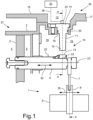
- FIG. 1 schematically a section of an automated manual transmission 1 with a transmission shaft 9, on which a sliding sleeve 8 is arranged to be axially movable.
- the sliding sleeve 8 is connected to a shift fork 7, which can be actuated by a shift actuator 37.
- the switching actuator 37 has a switching piston 2, which is guided in an axially displaceable manner in a switching cylinder 3.
- the switching piston 2 separates a first pressure chamber 4 and a second pressure chamber 5 from each other.
- the two pressure chambers 4, 5 can be filled with a pressure medium or emptied by it, so that the switching piston 2 can be actuated alternately, for example pneumatically.
- a piston rod 6 is attached to the switching piston 2.
- the possible linear ones Directions of movement 32 of the switching piston 2 and the piston rod 6 coaxial with their longitudinal axis 23 are indicated by a double arrow.
- One end of the shift fork 7 is connected to the piston rod 6 and the other end engages in an annular groove in the sliding sleeve 8.
- the switching piston 2, the piston rod 6, the switching fork 7 and the sliding sleeve 8 are thus coupled to one another in terms of movement.
- the sliding sleeve 8 is adjusted in one of the two axial directions by the axial movement of the switching piston 2 via the switching fork 7.
- the manual transmission 1 or the shifting actuator 37 has a device 30 with a Hall sensor device 10 for detecting the respective current position X of the shift fork 7.
- the Hall sensor device 10 has a 3D Hall sensor 11 and a magnet 13 assigned to it, the magnet 13 acting as a signal generator and the 3D Hall sensor 11 acting as a signal receiver.
- the magnet 13 is arranged on the radial lateral surface 22 of the piston rod 6 adjacent to the engagement area of the shift fork 7 and fastened there in a recess 33.
- the 3D Hall sensor 11 consists of a sensor head 14 and a sensor finger 15, which together with the sensor head 14 forms a component.
- the 3D Hall sensor 11 is inserted into a bore 16 in a housing wall 17 of a gear housing 18, with the sensor finger 15 protruding into a wet area formed as an oil space 19 within the gear housing 18 and pointing with its free end towards the magnet 13.
- the sensor head 14 has an electrical interface 24, which is located in a dry area 12 outside the oil space 19.
- a sensor line 36 which is connected to a control device 31, is connected to this electrical interface 24.
- This control device 31 commands using the Information supplied by the 3D Hall sensor 11 includes, among other things, switching valves (not shown here), which alternately enable an inflow of pressure medium into the two pressure chambers 4, 5 or empty them of the pressure medium. It can also be seen that the 3D Hall sensor 11 is sealed in an oil-tight manner relative to the housing wall 17 by means of a seal 20 designed as a sealing ring.
- the magnet 13 nestles against the lateral surface 22 of the piston rod 6 in a form-fitting manner.
- the width of the magnet 13 in the longitudinal axis direction of the piston rod 6 is adapted to the opposite width of the sensor finger 15 ( Fig. 1 ).
- the length of the magnet 13 in the circumferential direction of the piston rod 6 is, however, adapted to a rotation angle 21 of the piston rod 6 about its longitudinal axis 23, indicated by the double arrow ( Fig. 2 ).
- the magnetic field of the magnet 13 is in any case sufficiently dimensioned to be detected by the 3D Hall sensor 11 even in the event of an undesirable rotation of the piston rod 6 by an angle of rotation 21.
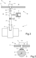
- Fig. 3 shows an embodiment according to the invention.
- the piston rod 6 is connected to the shift fork 7 in an articulated manner.
- the piston rod 6 presses on an upper part 26 of the shift fork 7 above a pivot bearing 25 or pulls on it, whereby the shift fork 7 is pivoted.
- a magnet 28 is attached here directly to the free end of the shift fork 7 remote from the shift sleeve, directly adjacent to a 3D Hall sensor 29. With its lower part 27, the shift fork 7 engages in a groove in the sliding sleeve 8 and moves it axially in the manner described Giveaway movement.
- the 3D Hall sensor 29 can measure the curve movement of the shift fork 7 via the relative position or change in position of the magnetic field to the 3D Hall sensor 29 and convert it into an axial position of the shift fork 7 or sliding sleeve 8. If sensor-side electronics are not capable of this, this conversion takes place in the aforementioned control device 31.
Description
Die Erfindung betrifft eine Vorrichtung mit einer Hall-Sensoreinrichtung zur Positionserfassung einer Schaltgabel in einem Schaltgetriebe, wobei die Schaltgabel mit einer Kolbenstange eines in einem Schaltzylinder axial beweglich geführten Schaltkolbens wirkverbundenen ist sowie in eine axial verschiebbar auf einer Getriebewelle angeordnete Schiebemuffe eingreift, um diese Schiebemuffe zum Ein- oder Auslegen einer Übersetzungsstufe des Schaltgetriebes zu verschieben. Außerdem betrifft die Erfindung ein Verfahren zur Positionserfassung einer Schaltgabel in einem Schaltgetriebe mit einer solchen Vorrichtung.The invention relates to a device with a Hall sensor device for detecting the position of a shift fork in a manual transmission, the shift fork being operatively connected to a piston rod of a switching piston guided in an axially movable manner in a shift cylinder and engaging in an axially displaceable sliding sleeve arranged on a transmission shaft in order to move this sliding sleeve to the To shift the engagement or disengagement of a gear ratio of the manual transmission. The invention also relates to a method for detecting the position of a shift fork in a manual transmission with such a device.
Die Steuerung eines automatisierten Schaltgetriebes erfordert zum Wechsel zwischen verschiedenen Übersetzungsstufen eine Information über den jeweiligen aktuellen Gangwechselstatus. Dafür wird in der Regel eine Positionserfassung einer Schaltgabel beziehungsweise einer durch diese betätigten Schiebemuffe durchgeführt, wobei die Schiebemuffe zum Einlegen einer Übersetzungsstufe ein Gangrad mit einer Welle drehfest verbindet und dieses zum Auslegen der Übersetzungsstufe wieder löst. Die Position der Schaltgabel wird einer elektronischen Steuerungseinheit des Schaltgetriebes zur Verfügung gestellt, welche hieraus Schaltbefehle ermittelt und versendet.The control of an automated manual transmission requires information about the current gear change status in order to change between different gear ratios. For this purpose, a position detection of a shift fork or a sliding sleeve actuated by it is usually carried out, whereby the sliding sleeve connects a gear wheel to a shaft in a rotationally fixed manner to insert a gear ratio and releases this again to design the gear ratio. The position of the shift fork is made available to an electronic control unit of the manual transmission, which determines and sends shift commands from this.
Meistens erfolgt die Messung einer relevanten axialen Position eines diesbezüglichen Stellglieds über die Erfassung einer Linearbewegung einer Schaltschiene, Schubstange oder dergleichen mit einem rein linear messenden Sensor, wie beispielsweise einem induktiven Messsystem oder einem auf dem Hall-Effekt beruhenden einfachen Hall-Sensor. Soll die Schaltgabelbewegung beziehungsweise Schaltgabelposition direkt gemessen werden, ist dies mit herkömmlichen Sensoren nur bei linear bewegten Schaltgabeln möglich. Für Getriebekonstruktionen, bei denen eine Schaltgabel zum Ein- oder Auslegen einer Übersetzungsstufe eine Schwenkbewegung ausführt, sind Linearsensoren kaum geeignet, da der Signalgeber nicht direkt an der Schaltgabel sondern nur an einem mit dieser zusammenwirkenden linear bewegten Stellglied, beispielsweise einer Kolbenstange oder einem Schaltkolben, angebracht werden kann.Most of the time, the measurement of a relevant axial position of a relevant actuator is carried out by detecting a linear movement of a switching rail, push rod or the like with a purely linear measuring sensor, such as an inductive measuring system or a simple Hall sensor based on the Hall effect. If the shift fork movement or shift fork position is to be measured directly, this is only possible with conventional sensors for linearly moved shift forks. Linear sensors are hardly suitable for transmission designs in which a shift fork performs a pivoting movement to engage or disengage a gear ratio, since the signal generator is not attached directly to the shift fork but only to a linearly moved actuator that interacts with it, for example a piston rod or a shift piston can be.
Eine indirekte Positionserfassung einer verschwenkten Schaltgabel mit einem Linearsensor ist somit zwar an sich möglich, es hat sich allerdings herausgestellt, dass eine derartige Positionsmessung mit einem Signalgeber, welcher an einem mit einer Schaltgabel in Wirkverbindung stehenden Stellglied zum Betätigen der Schaltgabel angebracht ist, mit einer rein linearen Messmethode zu Problemen führen kann. Schon ein geringes konstruktions-, fertigungs-, oder verschleißbedingtes freies Spiel, welches sich in der Übertragungskette zwischen einem Stellglied, das dann den Signalgeber trägt, und der Schaltgabel, deren Position zu bestimmen ist, auswirkt, kann zu Messfehlern führen. Ein solches Spiel kann beispielsweise zwischen einem bewegten Schaltkolben oder einer bewegten Kolbenstange als Träger des Signalgebers und einem feststehenden Schaltzylinder, in dem der Schaltkolben geführt ist, auftreten. Dieses Spiel wird insbesondere dann relevant, wenn es zu einer Verdrehungsstellung des Signalgebers gegenüber dem Signalnehmer kommt, beispielsweise aufgrund einer Drehbewegung einer den Signalgeber tragenden Kolbenstange um deren Längsachse während ihrer axialen Stellbewegung zum Betätigen der Schaltgabel. Dies kann zu einem axialen Versatz des Sensorsignals gegenüber der tatsächlichen Schaltgabelposition oder zu Signalrauschen bis hin zum völligen Ausfall des Messsignals führen. Angestrebt wird daher die Möglichkeit einer direkten Positionserfassung verschwenkt oder linear bewegter Schaltgabeln und/oder die Möglichkeit einer betriebssicheren indirekten Positionserfassung solcher Schaltgabeln.Although an indirect position detection of a pivoted shift fork with a linear sensor is possible, it has turned out that one Such position measurement with a signal transmitter, which is attached to an actuator that is in operative connection with a shift fork for actuating the shift fork, can lead to problems with a purely linear measurement method. Even a small amount of free play due to design, manufacturing or wear, which affects the transmission chain between an actuator, which then carries the signal transmitter, and the shift fork, whose position must be determined, can lead to measurement errors. Such play can occur, for example, between a moving switching piston or a moving piston rod as a carrier of the signal transmitter and a stationary switching cylinder in which the switching piston is guided. This play becomes particularly relevant if the signal transmitter is in a twisting position relative to the signal receiver, for example due to a rotational movement of a piston rod carrying the signal transmitter about its longitudinal axis during its axial actuating movement to actuate the shift fork. This can lead to an axial offset of the sensor signal compared to the actual shift fork position or to signal noise or even a complete failure of the measurement signal. The aim is therefore to have the possibility of direct position detection of pivoted or linearly moved shift forks and/or the possibility of operationally reliable indirect position detection of such shift forks.
Es ist für bestimmte Fahrzeugfunktionen zur Positionserfassung von Komponenten bereits bekannt, in mehreren Dimensionen mehrere Linearsensoren, wie beispielsweise induktive Messsysteme oder einen integrierten Raumsensor, wie etwa einen 3D-Hall-Sensor einzusetzen. Aus der
Aus der
Aus der
Vor diesem Hintergrund lag der Erfindung die Aufgabe zugrunde, eine Vorrichtung zur Positionserfassung einer Schaltgabel in einem Schaltgetriebe vorzuschlagen, die in der Messgenauigkeit sowie Zuverlässigkeit verbessert ist und zugleich eine Kostensenkung bei der Getriebeherstellung ermöglicht. Eine weitere an die Erfindung gerichtete Aufgabe bestand darin, ein Verfahren zur Positionserfassung einer Schaltgabel in einem Schaltgetriebe mit einer solchen Vorrichtung anzugeben. Insbesondere soll eine solche Vorrichtung für ein automatisiertes Schaltgetriebe im Antriebsstrang eines Fahrzeugs geeignet sein.Against this background, the invention was based on the object of proposing a device for detecting the position of a shift fork in a manual transmission, which is improved in terms of measurement accuracy and reliability and at the same time enables costs to be reduced in transmission production. Another object addressed to the invention was to provide a method for detecting the position of a shift fork in a manual transmission using such a device. In particular, such a Device for an automated manual transmission in the drive train of a vehicle may be suitable.
Die Lösung dieser Aufgabe ergibt sich aus den Merkmalen der unabhängigen Ansprüche, während vorteilhafte Ausgestaltungen und Weiterbildungen der Erfindung den Unteransprüchen entnehmbar sind.The solution to this problem results from the features of the independent claims, while advantageous refinements and developments of the invention can be found in the subclaims.
Der Erfindung lag die Erkenntnis zugrunde, dass in einem Schaltgetriebe ein herkömmlicher Positionssensor, welcher nur Linearbewegungen messen kann, nicht direkt an Schaltgabeln nutzbar ist, welche zur Betätigung einer Schiebemuffe verschwenkt werden müssen. Außerdem ist ein solcher herkömmlicher Positionssensor auch nur bedingt für solche Stellglieder geeignet, die zwar im Wesentlichen eine axiale Stellbewegung ausführen, jedoch auch noch andere, an sich unerwünschte Bewegungsfreiheitsgrade aufweisen können.The invention was based on the finding that in a manual transmission a conventional position sensor, which can only measure linear movements, cannot be used directly on shift forks, which have to be pivoted to operate a sliding sleeve. In addition, such a conventional position sensor is only suitable to a limited extent for actuators which, although essentially carry out an axial actuating movement, can also have other, inherently undesirable degrees of freedom of movement.
Ein 3D-Hall-Sensor ermöglicht hingegen sowohl die Messung von Linearbewegungen als auch die Erfassung von Kurven- und/oder Drehbewegungen eines auf einem Stellglied angebrachten Signalgebers relativ zum Sensor. Ein derartiger Sensor kann somit auch an solchen Stellgliedern genutzt werden, die dreidimensionale Bewegungen ausführen, da das Magnetfeld eines Signalgebers, welcher an dem betreffenden Stellglied befestigt ist und dessen Bewegung mitmacht, durch den 3D-Hall-Sensor in Abstand und Winkel räumlich aufgelöst werden kann. Dies ermöglicht es, die jeweilige axiale Stellung einer Schiebemuffe, welche bei Schaltvorgängen durch das Stellglied betätigt wird, exakt zu ermitteln, auch wenn die genannte Aktuatorik unter Verschleißerscheinungen leidet. Die Hall-Sensortechnik setzt dabei nicht voraus, dass sich das Target beziehungsweise das Magnetfeld während der Messung bewegt, also dass jederzeit, auch bei stehendem Stellglied, die Positionsbestimmung angefordert werden kann. Die Flexibilität verschiedener Anordnungsmöglichkeiten einer solchen Sensorik zur Positionserfassung erlaubt es zudem, die notwendige elektrische Verkabelung des Hall-Sensors aus einem Nassbereich des Getriebes in einen dazu benachbarten Trockenbereich zu verlagern.A 3D Hall sensor, on the other hand, enables both the measurement of linear movements and the detection of curved and/or rotary movements of a signal transmitter mounted on an actuator relative to the sensor. Such a sensor can therefore also be used on actuators that carry out three-dimensional movements, since the magnetic field of a signal transmitter, which is attached to the actuator in question and follows its movement, can be spatially resolved in distance and angle by the 3D Hall sensor . This makes it possible to precisely determine the respective axial position of a sliding sleeve, which is actuated by the actuator during switching operations, even if the actuator system mentioned suffers from signs of wear. The Hall sensor technology does not require that the target or the magnetic field moves during the measurement, meaning that the position determination can be requested at any time, even when the actuator is stationary. The flexibility of various arrangement options for such a sensor system for position detection also allows the necessary electrical wiring of the Hall sensor to be relocated from a wet area of the transmission to an adjacent dry area.
Die Erfindung geht daher zunächst aus von einer Vorrichtung mit einer Hall-Sensoreinrichtung zur Positionserfassung einer Schaltgabel in einem Schaltgetriebe, wobei die Schaltgabel mit einer Kolbenstange eines in einem Schaltzylinder axial beweglich geführten Schaltkolbens wirkverbundenen ist sowie in eine axial verschiebbar auf einer Getriebewelle angeordnete Schiebemuffe eingreift, um diese Schiebemuffe zum Ein- oder Auslegen einer Übersetzungsstufe des Schaltgetriebes zu verschieben.The invention is therefore initially based on a device with a Hall sensor device for detecting the position of a shift fork in a manual transmission, the shift fork having a piston rod which is guided in an axially movable manner in a shift cylinder Switching piston is operatively connected and engages in an axially displaceable sliding sleeve arranged on a transmission shaft in order to move this sliding sleeve for engaging or disengaging a gear ratio of the manual transmission.
Zur Lösung der gestellten Aufgabe hinsichtlich der Schaffung einer Vorrichtung zur Positionserfassung einer Schaltgabel in einem Schaltgetriebe sieht die Erfindung vor, dass an der Schaltgabel ein einziger Magnet als Signalgeber angeordnet ist, dass ein relativ zu dem Magnet ortsfest angeordneter 3D-Hall-Sensor als Signalnehmer vorhanden ist, mittels dem ein durch den Magnet erzeugtes Magnetfeld räumlich erfassbar ist, dass der 3D-Hall-Sensor mit einer elektronischen Steuerungseinheit verbunden ist, und dass die Steuerungseinheit derart ausgebildet ist, dass mit dieser aus der jeweiligen Relativposition zwischen dem Magnet und dem 3D-Hall-Sensor die aktuelle Position der Schaltgabel bestimmbar sowie als Signal zur Verfügung stellbar ist, wobei lineare Bewegungen, rotatorische Bewegungen und/oder Schwenkbewegungen der Schaltgabel berücksichtigbar sind.In order to solve the problem set with regard to creating a device for detecting the position of a shift fork in a manual transmission, the invention provides that a single magnet is arranged on the shift fork as a signal transmitter and that a 3D Hall sensor, which is stationary relative to the magnet, is present as a signal receiver is, by means of which a magnetic field generated by the magnet can be spatially detected, that the 3D Hall sensor is connected to an electronic control unit, and that the control unit is designed such that it can be used from the respective relative position between the magnet and the 3D Hall sensor, the current position of the shift fork can be determined and made available as a signal, with linear movements, rotational movements and / or pivoting movements of the shift fork being taken into account.
Die Anwendung der 3D-Hall-Technik in einem Schaltgetriebe ermöglicht demnach eine sehr flexible Anordnung eines Signalgebers in dem Getriebe, unabhängig davon, ob ein zu messendes Stellglied axial verschoben oder verschwenkt wird. Der Signalgeber kann somit direkt an dem betreffenden, aktuatorfernen Stellglied angebracht sein, wodurch sich schon per se eine verbesserte Messgenauigkeit ergibt, da keine Messfehler durch eine mechanische Übertragungskette entstehen können. Insbesondere können auch Kurvenbewegungen eines Stellglieds erfasst werden. Einfache lineare Messungen sind selbstverständlich auch möglich.The use of 3D Hall technology in a manual transmission therefore enables a very flexible arrangement of a signal generator in the transmission, regardless of whether an actuator to be measured is axially displaced or pivoted. The signal transmitter can therefore be attached directly to the actuator in question, which is remote from the actuator, which in itself results in improved measurement accuracy, since no measurement errors can arise due to a mechanical transmission chain. In particular, curved movements of an actuator can also be detected. Simple linear measurements are of course also possible.
Die Erfindung ist ebenso vorteilhaft für Anordnungen geeignet, in denen der Signalgeber beispielsweise konstruktions- oder bauraumbedingt nicht direkt an dem zu messenden Stellglied angebracht werden kann oder soll. In diesen Fällen können Fehlereinflüsse oder Messsignalbeeinträchtigungen aufgrund von überlagerten linearen und nichtlinearen Bewegungen an einem Stellglied oder zwischen mehreren an der Stellaufgabe beteiligten Stellgliedern kompensiert werden, wie an den im Folgenden beschriebenen Ausführungsformen der Erfindung verdeutlicht wird. Dadurch wird eine zuverlässige und genaue Positionserfassung einer Schaltgabel sichergestellt. Insbesondere kann mit Hilfe des 3D-Hall-Sensors zuverlässig und exakt festgestellt werden, ob eine angesteuerte Schaltposition des Schaltgetriebes erreicht ist, selbst dann, wenn an dem Stellglied, an dem der Signalgeber angeordnet ist, Störeinflüsse bei der zu messenden Stellbewegung auftreten.The invention is also advantageously suitable for arrangements in which the signal generator cannot or should not be attached directly to the actuator to be measured, for example due to construction or installation space. In these cases, error influences or measurement signal impairments due to superimposed linear and nonlinear movements on an actuator or between several actuators involved in the actuating task can be compensated for, as is illustrated by the embodiments of the invention described below. This ensures reliable and accurate position detection of a shift fork. In particular, the 3D Hall sensor can be used to reliably and precisely determine whether a controlled switching position of the manual transmission has been reached, even if interference occurs in the actuating movement to be measured on the actuator on which the signal transmitter is arranged.
3D-Hall-Sensoren sind als kompakte Halbleiterbauteile in verschiedenen Ausführungen käuflich verfügbar. Da nur ein einziger 3D-Hall-Sensor als Signalnehmer für die Positionserfassung benötigt wird, kann zudem im Vergleich zu herkömmlichen Anordnungen, welche für räumliche Magnetfeldmessungen mehrere Sensoren benötigen, Bauraum eingespart werden. Zweckmäßigerweise kann der Sensor für den größtmöglichen Abstand zu einem Signalgeber im Getriebe ausgelegt werden. Dadurch ist der Sensor für verschiedene Montagepositionen geeignet und es sind keine aufwändigen Anpassungen an den jeweiligen Einbauort in einem vorhandenen Schaltgetriebe erforderlich. Dadurch können sich Fertigungs- und Entwicklungskosten verringern.3D Hall sensors are commercially available as compact semiconductor components in various designs. Since only a single 3D Hall sensor is required as a signal receiver for position detection, installation space can also be saved compared to conventional arrangements, which require several sensors for spatial magnetic field measurements. The sensor can expediently be designed for the greatest possible distance from a signal generator in the transmission. This means that the sensor is suitable for various mounting positions and no complex adjustments to the respective installation location in an existing manual transmission are required. This can reduce manufacturing and development costs.
Der Schutzbereich wird durch die Patentansprüche bestimmt, wobei die Beschreibung und die Zeichnungen jedoch nur zur Auslegung der Patentansprüche heranzuziehen sind.The scope of protection is determined by the patent claims, although the description and drawings are only to be used for the interpretation of the patent claims.
Gemäß einem nicht erfindungsgemäßen Beispiel kann vorgesehen sein, dass an der Kolbenstange oder an dem Schaltkolben ein Magnet angeordnet und derart ausgebildet ist, dass im Zusammenwirken mit einem zugeordneten 3D-Hall-Sensor eine Linearbewegung der Kolbenstange oder des Schaltkolbens erfassbar ist, und dass eine der Linearbewegung der Kolbenstange oder des Schalkolbens überlagerte lagerungsbedingte und/oder verschleißbedingte Drehbewegung der Kolbenstange oder des Schaltkolbens um deren Längsachse durch eine an einen maximal möglichen Verdrehwinkel gegenüber dem 3D-Hall-Sensor angepasste Dimensionierung des Magneten bei der Erfassung des Magnetfelds kompensierbar ist, oder dass eine derartige Störbewegung bei der Bestimmung der Position der Schaltgabel rechnerisch in dem Steuerungsgerät eliminierbar ist.According to an example not according to the invention, it can be provided that a magnet is arranged on the piston rod or on the switching piston and is designed in such a way that a linear movement of the piston rod or the switching piston can be detected in cooperation with an associated 3D Hall sensor, and that one of the Linear movement of the piston rod or the switching piston superimposed on storage and / or wear-related rotational movement of the piston rod or the switching piston about its longitudinal axis can be compensated for by a dimensioning of the magnet adapted to a maximum possible angle of rotation relative to the 3D Hall sensor when detecting the magnetic field, or that a Such disruptive movement can be eliminated mathematically in the control device when determining the position of the shift fork.
Demnach kann gemäß einer nicht erfindungsgemäßen Beispielerklärung der Signalgeber an der Kolbenstange oder an dem Schaltkolben eines Aktuators angebracht sein, welcher durch eine Getriebesteuerung zur Betätigung angesteuert wird und die Schaltgabel beispielsweise elektropneumatisch betätigt. Die Kolbenstange führt eine Linearbewegung aus, um die Schaltgabel mit einer Stellkraft zu beaufschlagen. Die Stellposition im Getriebe wird bei dieser Ausführungsform nicht direkt an der Schaltgabel sondern an dem Schaltkolben beziehungsweise an der Kolbenstange erfasst. Der Signalgeber ist also nicht auf der Schaltgabel sondern an dem Schaltkolben oder an der Kolbenstange befestigt.Accordingly, according to an exemplary explanation not according to the invention, the signal transmitter can be attached to the piston rod or to the switching piston of an actuator, which is controlled for actuation by a transmission control and which actuates the shift fork, for example, electro-pneumatically. The piston rod performs a linear movement in order to apply a force to the shift fork. In this embodiment, the setting position in the transmission is not directly on the shift fork but on the shift piston or captured on the piston rod. The signal transmitter is therefore not attached to the shift fork but to the shift piston or the piston rod.
Die Lagerung des Schaltkolbens erzeugt allerdings nicht selten eine gewisse Drehung desselben um seine Längsachse, welches die Messung der axialen Stellposition erschwert oder gar unmöglich macht. Zusätzlich kann es auch durch fertigungsbedingte Toleranzen und Verschleiß zu einer nicht vernachlässigbaren Drehtoleranz des Schaltkolbens kommen. Dadurch variiert die Winkelstellung zwischen dem Signalgeber und dem ortsfesten Signalnehmer. Dies könnte bei der Verwendung eines Linearsensors zu einem starken Signalrauschen oder gar zum Verlust des Messsignals führen. Der 3D-Hall-Sensor kann diese Drehung des Schaltkolbens jedoch messtechnisch kompensieren, da er einen Raumwinkelbereich des dort befestigten Magneten erfassen kann. Diese Kompensation ist dadurch möglich, dass der Signalgeber, also der Magnet, in seiner Größe ausreichend ausgelegt ist, so dass der Signalempfänger das Magnetfeld des Magneten auch bei einer geringen Drehung des Schaltkolbens beziehungsweise der Kolbenstange detektieren sowie ein ausreichend starkes beziehungsweise genaues Messsignal erzeugen kann. Dadurch kann eine Signalverschlechterung aufgrund der Lagertoleranz des Schaltkolbens beziehungsweise der Schaltstange verhindert werden. Diese Anpassung der Dimensionierung des Magneten kann die Genauigkeit der Positionsmessung der Schaltgabel verbessern.However, the mounting of the switching piston often produces a certain rotation of the piston about its longitudinal axis, which makes measuring the axial position difficult or even impossible. In addition, manufacturing-related tolerances and wear can also lead to a non-negligible rotational tolerance of the switching piston. This means that the angular position between the signal transmitter and the stationary signal receiver varies. When using a linear sensor, this could lead to strong signal noise or even loss of the measurement signal. However, the 3D Hall sensor can compensate for this rotation of the switching piston using measurement technology, as it can detect a solid angle range of the magnet attached there. This compensation is possible because the signal transmitter, i.e. the magnet, is designed to be sufficiently large so that the signal receiver can detect the magnetic field of the magnet even with a small rotation of the switching piston or the piston rod and can generate a sufficiently strong or precise measurement signal. This can prevent signal degradation due to the bearing tolerance of the switching piston or the switching rod. This adjustment of the sizing of the magnet can improve the accuracy of the position measurement of the shift fork.
Eine weitere Möglichkeit oder eine zusätzlich Maßnahme kann darin bestehen, einen Parameter festzulegen, welcher den im Betrieb möglicherweise auftretenden Drehwinkel des Schaltkolbens beziehungsweise der Kolbenstange sowie ein dazu zu erwartendes Messsignal miteinander korreliert. Daraus kann ein Korrekturfaktor berechnet werden, mit dem das Messsignal multipliziert wird. Dies kann im 3D-Hall-Sensor selbst oder in einer elektronischen Steuerungseinheit erfolgen, welche an den Sensor angeschlossen ist. Dadurch wird das Messsignal rechnerisch unabhängig von einer Drehung des Schaltkolbens beziehungsweise der Kolbenstange. Diese Maßnahme kann ebenfalls die Genauigkeit der Positionsmessung der Schaltgabel verbessern.A further possibility or an additional measure can be to define a parameter which correlates the angle of rotation of the switching piston or the piston rod that may occur during operation and a measurement signal to be expected in relation to one another. From this, a correction factor can be calculated by which the measurement signal is multiplied. This can be done in the 3D Hall sensor itself or in an electronic control unit that is connected to the sensor. This makes the measurement signal mathematically independent of a rotation of the switching piston or the piston rod. This measure can also improve the accuracy of the position measurement of the shift fork.
Außerdem kann gemäß einem nicht erfindungsgemäßen Beispiel vorgesehen sein, dass der Magnet auf der Mantelfläche der Kolbenstange befestigt oder in einer taschenförmigen Ausnehmung der Kolbenstange festsitzend integriert ist. Demnach kann der Magnet in seiner Funktion als Signalgeber einfach auf der Kolbenstange oder auf dem Schaltkolben aufgesetzt und befestigt sein. Es ist besonders vorteilhaft, obwohl es nicht durch den Wortlaut des ersten Anspruchs abgedeckt worden ist, den Magneten direkt in den Schaltkolben beziehungsweise in die Kolbenstange zu integrieren, so dass dessen Oberfläche einen Teil der Mantelfläche desselben bildet. Der Magnet kann beispielsweise als ein Ringsegment in eine entsprechende Ausnehmung der Kolbenstange eingefasst sein. Der Magnet nimmt dadurch keinen zusätzlichen Bauraum ein. Zudem wird durch die Integration des Magneten Material eingespart und die Masse des Schaltkolbens beziehungsweise der Kolbenstange nicht oder allenfalls unbedeutend erhöht. Außerdem wird durch die Integration des Magneten kein unerwünschtes Drehmoment auf die Bauteile ausgeübt.In addition, according to an example not according to the invention, it can be provided that the magnet is attached to the lateral surface of the piston rod or is firmly integrated in a pocket-shaped recess in the piston rod. Accordingly, the magnet can function as The signal transmitter can simply be placed and secured on the piston rod or on the switching piston. It is particularly advantageous, although it has not been covered by the wording of the first claim, to integrate the magnet directly into the switching piston or into the piston rod, so that its surface forms part of the lateral surface of the same. The magnet can, for example, be enclosed as a ring segment in a corresponding recess in the piston rod. The magnet therefore does not take up any additional space. In addition, the integration of the magnet saves material and the mass of the switching piston or the piston rod is not increased or at most is insignificantly increased. In addition, the integration of the magnet means that no unwanted torque is exerted on the components.
Gemäß einer Ausführungsform der Erfindung kann vorgesehen sein, dass zum Ein- oder Auslegen einer Übersetzungsstufe des Schaltgetriebes eine Schwenkbewegung der Schaltgabel vorgesehen ist, und dass der an der Schaltgabel angeordnete Magnet derart ausgebildet ist, dass in Zusammenwirkung mit einem zugeordneten 3D-Hall-Sensor die aus der Schwenkbewegung der Schaltgabel resultierende Position der Schaltgabel bestimmbar ist.According to one embodiment of the invention, it can be provided that a pivoting movement of the shift fork is provided for engaging or disengaging a gear ratio of the manual transmission, and that the magnet arranged on the shift fork is designed such that in cooperation with an associated 3D Hall sensor The position of the shift fork resulting from the pivoting movement of the shift fork can be determined.
Bei dieser Ausführungsform der Erfindung kann demnach der Signalgeber direkt auf einer Schaltgabel, welche zum Betätigen einer Schiebemuffe verschwenkt wird, angebracht sein. Der Signalgeber kann alternativ dazu in die Schaltgabel integriert sein. Der 3D-Hall-Sensor erfasst das Magnetfeld des Magneten bei der Schwenkbewegung der Schaltgabel und bestimmt daraus die Position der Schaltgabel und damit der Schiebemuffe, um den aktuellen Schaltzustand des Getriebes zu ermitteln und der Getriebesteuerung zur Verfügung zu stellen.In this embodiment of the invention, the signal generator can therefore be mounted directly on a shift fork, which is pivoted to operate a sliding sleeve. Alternatively, the signal generator can be integrated into the shift fork. The 3D Hall sensor detects the magnetic field of the magnet during the pivoting movement of the shift fork and uses this to determine the position of the shift fork and thus the sliding sleeve in order to determine the current switching state of the transmission and make it available to the transmission control.
Eine direkte Befestigung des Magneten an der Schaltgabel hat außerdem den Vorteil, dass eine gebrochene Schaltgabel oder eine gebrochene Verbindung zwischen der Schaltgabel und der Kolbenstange nun durch die Sensorik erkannt und durch eine Fehlermeldung signalisiert werden kann, da die Schaltgabel sich in diesem Fall nicht bewegt, obwohl der Schaltkolben betätigt wird. Dadurch kann das Schaltgetriebe vor Schäden geschützt sowie gegebenenfalls geeignete Maßnahmen eingeleitet und somit die Betriebssicherheit erhöht werden.Attaching the magnet directly to the shift fork also has the advantage that a broken shift fork or a broken connection between the shift fork and the piston rod can now be detected by the sensor system and signaled by an error message, since the shift fork does not move in this case. although the switching piston is actuated. This means that the manual transmission can be protected from damage and, if necessary, appropriate measures can be taken, thereby increasing operational safety.
Gemäß einer anderen Weiterbildung der Erfindung kann vorgesehen sein, dass zum Ein- oder Auslegen einer Übersetzungsstufe des Schaltgetriebes eine Linearbewegung der Schaltgabel vorgesehen ist, und dass der an der Schaltgabel angeordnete Magnet derart ausgebildet ist, dass in Zusammenwirkung mit einem zugeordneten 3D-Hall-Sensor die aus der Linearbewegung der Schaltgabel resultierende Position der Schaltgabel bestimmbar ist, wobei eine der Linearbewegung überlagerte nichtlineare Bewegung der Schaltgabel durch eine geeignete Dimensionierung des Magneten bei der Erfassung des Magnetfelds kompensierbar ist, oder dass eine derartige Störbewegung bei der Bestimmung der Position der Schaltgabel rechnerisch eliminierbar ist, wobei der einzige Magnet in seiner Größe ausreichend ausgelegt ist, so dass der Signalempfänger das Magnetfeld des Magneten auch bei einer geringen Drehung des Schaltkolbens beziehungsweise der Kolbenstange detektieren sowie ein ausreichend starkes beziehungsweise genaues Messsignal erzeugbar ist, und wobei eine Signalverschlechterung aufgrund der Lagertoleranz des Schaltkolbens beziehungsweise der Schaltstange verhindert wird.According to another development of the invention, it can be provided that a linear movement of the shift fork is provided for engaging or disengaging a gear ratio of the manual transmission, and that the magnet arranged on the shift fork is designed in such a way that in cooperation with an associated 3D Hall sensor the position of the shift fork resulting from the linear movement of the shift fork can be determined, wherein a non-linear movement of the shift fork superimposed on the linear movement can be compensated for by suitable dimensioning of the magnet when detecting the magnetic field, or such an interference movement can be eliminated computationally when determining the position of the shift fork is, wherein the size of the single magnet is sufficiently designed so that the signal receiver can detect the magnetic field of the magnet even with a small rotation of the switching piston or the piston rod and a sufficiently strong or precise measurement signal can be generated, and a signal deterioration due to the bearing tolerance of the Switching piston or the switching rod is prevented.
Demnach kann die Vorrichtung gemäß der Erfindung bei beiden üblichen Bauformen der Schiebemuffenbetätigung, also entweder über eine Schaltgabelverschwenkung oder über eine Schaltgabelverschiebung, vorteilhaft genutzt werden. Die Vorrichtung kann direkt an der Schaltgabel deren Position messen oder indirekt über ein die Schaltgabel betätigendes Stellglied, unabhängig von der jeweiligen Art des Stellwegs der Schaltgabel. Dabei können Störeinflüsse, welche die Messung oder das Messsignal ungünstig beeinträchtigen, mittels der 3D-Hall-Messtechnik im Steuerungsgerät oder auch schon in der Elektronik des 3D-Hall-Sensors ausgefiltert werden.Accordingly, the device according to the invention can be used advantageously in both usual designs of sliding sleeve actuation, i.e. either via a shift fork pivot or a shift fork shift. The device can measure the position of the shift fork directly or indirectly via an actuator that actuates the shift fork, regardless of the respective type of travel of the shift fork. Interferences that adversely affect the measurement or the measurement signal can be filtered out using the 3D Hall measurement technology in the control device or in the electronics of the 3D Hall sensor.
Gemäß einer weiteren Ausführungsform der Erfindung kann vorgesehen sein, dass der 3D-Hall-Sensor zumindest teilweise außerhalb eines Ölraums des Schaltgetriebes angeordnet ist. Dies kann dadurch konkretisiert sein, dass der 3D-Hall-Sensor einen Sensorkopf mit einer elektrischen Schnittstelle sowie einen mit dem Sensorkopf verbundenen Sensorfinger aufweist. Der Sensorfinger ragt dabei durch eine Gehäusewand in den Ölraum des Schaltgetriebes in Richtung zum zugeordneten Magneten hinein, und der Sensorkopf ist an einer Außenseite der Gehäusewand angeordnet sowie dort gegenüber dem Ölraum öldicht befestigt.According to a further embodiment of the invention, it can be provided that the 3D Hall sensor is at least partially arranged outside an oil chamber of the manual transmission. This can be specified in that the 3D Hall sensor has a sensor head with an electrical interface and a sensor finger connected to the sensor head. The sensor finger protrudes through a housing wall into the oil chamber of the manual transmission in the direction of the associated magnet, and the sensor head is arranged on an outside of the housing wall and fastened there in an oil-tight manner relative to the oil chamber.
Die 3D-Hall-Sensoreinrichtung zur Schaltgabelpositionsmessung erlaubt flexible Möglichkeiten der Positionierung von Signalnehmer und zugehörigem Signalgeber in einem Schaltgetriebe. Insbesondere ist es möglich, den Signalnehmer aus dem Nassbereich des Getriebes zu entfernen, so dass sich zumindest der elektrische Anschluss des Signalnehmers in einem trockenen Bereich befindet. Der Sensorfinger kann in den Ölbereich hineinragen, um die Position des Signalgebers zu messen. Dadurch entfallen auch elektrische Leitungen für die Verkabelung des Sensors im Nassbereich des Getriebes, wo der zur Verfügung stehende Bauraum ohnehin oft recht gering ist. Der Aufwand für den elektrischen Sensorkontakt ist somit wesentlich geringer und weniger anfällig für Kabelschäden als bei konventionellen technischen Lösungen.The 3D Hall sensor device for shift fork position measurement allows flexible options for positioning the signal receiver and associated signal transmitter in a manual transmission. In particular, it is possible to remove the signal receiver from the wet area of the transmission, so that at least the electrical connection of the signal receiver is in a dry area. The sensor finger can extend into the oil area to measure the position of the signal transmitter. This also eliminates the need for electrical cables for wiring the sensor in the wet area of the transmission, where the available installation space is often quite small anyway. The effort required for the electrical sensor contact is therefore significantly lower and less susceptible to cable damage than with conventional technical solutions.
Gemäß einer weiteren Ausführungsform der Erfindung kann vorgesehen sein, dass der 3D-Hall-Sensor vollständig außerhalb des Ölraums des Schaltgetriebes angeordnet ist. Demnach ist es im Idealfall sogar möglich, die Position des Signalgebers durch eine aus einem nichtmagnetischen Material, wie beispielsweise Aluminium, bestehende Gehäusewand abzutasten. Beispielsweise kann bei Getriebestrukturen, bei denen der Abstand zwischen Signalgeber und Signalnehmer relativ klein und die Wandstärke des Gehäuses vergleichsweise gering gestaltet werden kann, eine ausreichende Signalstärke erreicht werden, die es ermöglicht, den Sensor komplett im Trockenbereich anzubringen. Dadurch entfallen sowohl elektrische Kabel innerhalb des Getriebegehäuses als auch Bohrungen und Dichtungen in Wandungen des Getriebegehäuse für den Sensor. Hierdurch kann der Aufwand für die Implementierung der 3D-Hall-Sensoreinrichtung zur Positionserfassung einer Schaltgabel beziehungsweise einer Schiebemuffe noch weiter verringert werden.According to a further embodiment of the invention, it can be provided that the 3D Hall sensor is arranged completely outside the oil chamber of the manual transmission. Ideally, it is even possible to sense the position of the signal transmitter through a housing wall made of a non-magnetic material, such as aluminum. For example, in transmission structures in which the distance between the signal transmitter and the signal receiver can be made relatively small and the wall thickness of the housing can be made comparatively small, a sufficient signal strength can be achieved, which makes it possible to install the sensor completely in the dry area. This eliminates the need for electrical cables within the gearbox housing as well as holes and seals in the walls of the gearbox housing for the sensor. As a result, the effort for implementing the 3D Hall sensor device for detecting the position of a shift fork or a sliding sleeve can be reduced even further.
Außerdem betrifft die Erfindung ein Verfahren zur Positionsbestimmung einer Schaltgabel in einem Schaltgetriebe mittels einer Hall-Sensoreinrichtung, wobei die Schaltgabel mit einer Kolbenstange eines in einem Schaltzylinder axial beweglich geführten Schaltkolbens wirkverbundenen ist sowie in eine auf einer Getriebewelle axial verschiebbare Schiebemuffe eingreift, um diese zum Ein- oder Auslegen einer Übersetzungsstufe des Schaltgetriebes zu verschieben, und wobei an der Schaltgabel ein einziger Magnet der Hall-Sensoreinrichtung befestigt ist. Hierbei ist verfahrensgemäß vorgesehen, dass mittels eines ortsfesten 3D-Hall-Sensors das Magnetfeld des Magneten räumlich erfasst wird, welcher bei einer linearen, rotatorischen Stellbewegung und Schwenkbewegung der Schaltgabel mit diesen mitbewegt wird sowie dabei seine relative Lage zu dem ortsfesten 3D-Hall-Sensor verändert, und dass aus dem Sensorsignal des 3D-Hall-Sensors die aktuelle Position der Schaltgabel bestimmt wird.The invention also relates to a method for determining the position of a shift fork in a manual transmission by means of a Hall sensor device, wherein the shift fork is operatively connected to a piston rod of a shift piston guided in an axially movable manner in a shift cylinder and engages in an axially displaceable sliding sleeve on a transmission shaft in order to engage it - or to move a gear ratio of the manual transmission, and a single magnet of the Hall sensor device is attached to the shift fork. According to the method, it is provided that the magnetic field of the magnet is spatially detected by means of a stationary 3D Hall sensor, which is moved along with the shift fork during a linear, rotary actuating movement and pivoting movement of the shift fork, as well as its relative Position changed relative to the stationary 3D Hall sensor, and that the current position of the shift fork is determined from the sensor signal of the 3D Hall sensor.
Schließlich betrifft die Erfindung auch einen Aktuator für ein automatisiertes Schaltgetriebe eines Kraftfahrzeugs, welcher eine Vorrichtung zur Positionserfassung einer von diesem direkt oder indirekt zu betätigenden Schaltgabel des Schaltgetriebes aufweist, wobei diese Vorrichtung zumindest die Merkmale von wenigstens einem der zuvor geschilderten Vorrichtungsansprüche aufweist sowie zur Durchführung des beanspruchten Verfahrens ausgestaltet ist. Hierbei ist es vorteilhaft, wenn das Verfahren bei jedem Schaltvorgang und an jeder der an dem jeweiligen Schaltvorgang aktiv beteiligten Schaltgabeln durchgeführt wird. Dadurch ist stets eine einwandfreie Schaltsteuerung des Schaltgetriebes gewährleistet.Finally, the invention also relates to an actuator for an automated manual transmission of a motor vehicle, which has a device for detecting the position of a shift fork of the manual transmission that can be actuated directly or indirectly by this, this device having at least the features of at least one of the previously described device claims and for carrying out the claimed method is designed. It is advantageous here if the method is carried out with every switching process and on each of the shift forks actively involved in the respective switching process. This always ensures perfect shift control of the manual transmission.
Die Erfindung wird nachstehend anhand von in der beigefügten Zeichnung dargestellten Ausführungsbeispielen näher erläutert. In der Zeichnung zeigt
-
Fig. 1 einen schematischen Ausschnitt eines Schaltgetriebes und eines Schaltaktuators mit einer Hall-Sensoreinrichtung gemäß nicht erfindungsgemäßen Beispielerklärung, -
Fig. 2 zeigt die nicht erfindungsgemäße Hall-Sensoreinrichtung gemäß der genannten Beispielerklärung vonFig. 1 in einem schematisch vereinfachten sowie vergrößerten Querschnitt, und -
Fig. 3 eine schematische Darstellung einer Ausführungsform einer Hall-Sensoreinrichtung gemäß der Erfindung.
-
Fig. 1 a schematic section of a manual transmission and a switching actuator with a Hall sensor device according to an example explanation not according to the invention, -
Fig. 2 shows the Hall sensor device not according to the invention according to the example explanation mentioned byFig. 1 in a schematically simplified and enlarged cross section, and -
Fig. 3 a schematic representation of an embodiment of a Hall sensor device according to the invention.
Einige Bauelemente in den Figuren stimmen in ihrem Aufbau und/oder in ihrer Funktion überein, so dass diese zur Vereinfachung mit denselben Bezugsziffern bezeichnet sind. Demnach zeigt
Die Schaltgabel 7 ist mit ihrem einen Ende mit der Kolbenstange 6 verbunden und greift mit ihrem anderen Ende in eine Ringnut der Schiebemuffe 8 ein. Somit sind der Schaltkolben 2, die Kolbenstange 6, die Schaltgabel 7 und die Schiebemuffe 8 miteinander bewegungsgekoppelt. Bei einer Druckbeaufschlagung einer der beiden Druckräume 4, 5 wird durch die Axialbewegung des Schaltkolbens 2 über die Schaltgabel 7 die Schiebemuffe 8 in einer der beiden Axialrichtungen verstellt. In hier nicht dargestellter, jedoch an sich bekannter Weise wird beim Schalten eines Ganges des Schaltgetriebes die Schiebemuffe 8 mittels der Schaltgabel 7 über eine Schaltverzahnung eines Gangrads geschoben, wodurch das Gangrad drehfest mit der hier nur angedeuteten Getriebewelle 9 verbunden wird. Durch eine Schaltbewegung in der Gegenrichtung wird der eingelegte Gang wieder ausgelegt. Die lineare Schaltbewegung 35 der Schiebemuffe 9 ist durch einen Doppelpfeil angedeutet.One end of the
Das Schaltgetriebe 1 beziehungsweise der Schaltaktuator 37 weist eine Vorrichtung 30 mit einer Hall-Sensoreinrichtung 10 zur Erfassung der jeweiligen aktuellen Position X der Schaltgabel 7 auf. Die Position X der Schaltgabel 7 ist eindeutig mit der axialen Position der Schiebemuffe 8 und somit mit dem aktuellen Schaltzustand des Schaltgetriebes 1 verknüpft. Die Hall-Sensoreinrichtung 10 weist einen 3D-Hall-Sensor 11 und einen diesem zugeordneten Magnet 13 auf, wobei der Magnet 13 als Signalgeber und der 3D-Hall-Sensor 11 als Signalnehmer fungieren. Der Magnet 13 ist auf der radialen Mantelfläche 22 der Kolbenstange 6 benachbart zum Eingriffbereich der Schaltgabel 7 angeordnet und dort in einer Ausnehmung 33 befestigt.The
Der 3D-Hall-Sensor 11 besteht aus einem Sensorkopf 14 sowie einem Sensorfinger 15, welcher mit dem Sensorkopf 14 zusammen ein Bauteil bildet. Der 3D-Hall-Sensor 11 ist in eine Bohrung 16 in einer Gehäusewand 17 eines Getriebegehäuses 18 eingesetzt, wobei der Sensorfinger 15 in einen als Ölraum 19 innerhalb des Getriebegehäuses 18 ausgebildeten Nassbereich hineinragt und mit seinem freien Ende in Richtung zum Magneten 13 zeigt. Der Sensorkopf 14 weist eine elektrische Schnittstelle 24 auf, die sich in einem Trockenbereich 12 außerhalb des Ölraumes 19 befindet. An diese elektrische Schnittstelle 24 ist eine Sensorleitung 36 angeschlossen, welche mit einem Steuerungsgerät 31 verbunden ist. Dieses Steuerungsgerät 31 befehligt unter Nutzung der vom 3D-Hall-Sensor 11 gelieferten Informationen unter anderem hier nicht dargestellte Schaltventile, welche wechselweise einen Druckmittelzustrom in die beiden Drückräume 4, 5 ermöglichen oder diese von dem Druckmittel entleeren. Zudem ist erkennbar, dass der 3D-Hall-Sensor 11 gegenüber der Gehäusewand 17 mittels einer als Dichtring ausgebildeten Dichtung 20 öldicht abgedichtet ist.The
Wie aus
Um die Position X der Schaltgabel 7 zu bestimmen, erfasst der 3D-Hall-Sensor 11 das Magnetfeld des Magneten 13. Die Hall-Spannung, welche an dem 3D-Hall-Sensor 11 abgegriffen werden kann, ist mit der Relativposition zwischen dem Sensorfinger 15 und dem Magnetfeld beziehungsweise zwischen dem Sensorfinger 15 und dem Magneten 13 eindeutig korreliert. Wenn sich bei einer Axialbewegung der Kolbenstange 6 diese ungewollt etwas dreht, kann dies bei einer hier nicht näher erläuterten vektoriellen Messung und Auswertung des Magnetfelds im 3D-Hall-Sensor 11 oder im Steuerungsgerät 31 kompensiert werden, so dass das Ergebnis der Positionsbestimmung der Schaltgabel 7 nicht durch die überlagerte Drehbewegung verfälscht oder in seiner Amplitudenhöhe geschwächt wird.In order to determine the position and the magnetic field or between the
Der 3D-Hall-Sensor 29 kann die Kurvenbewegung der Schaltgabel 7 über die relative Lage beziehungsweise Lageänderung des Magnetfelds zum 3D-Hall-Sensor 29 messen und in eine axiale Position der Schaltgabel 7 beziehungsweise Schiebemuffe 8 umrechnen. Sofern eine sensorseitige Elektronik dazu nicht in der Lage ist, erfolgt diese Umrechnung in dem erwähnten Steuerungsgerät 31.The
- 11
- SchaltgetriebeManual transmission
- 22
- Schaltkolben, StellgliedSwitching piston, actuator
- 33
- Schaltzylinderswitching cylinder
- 44
- Erster DruckraumFirst printing room
- 55
- Zweiter DruckraumSecond pressure room
- 66
- Kolbenstange, StellgliedPiston rod, actuator
- 77
- Schaltgabel, StellgliedShift fork, actuator
- 88th
- SchiebemuffeSliding sleeve
- 99
- GetriebewelleTransmission shaft
- 1010
- Hall-SensoreinrichtungHall sensor device
- 1111
- 3D-Hall-Sensor (erstes Ausführungsbeispiel)3D Hall sensor (first embodiment)
- 1212
- TrockenbereichDry area
- 1313
- Magnet (erstes Ausführungsbeispiel)Magnet (first embodiment)
- 1414
- SensorkopfSensor head
- 1515
- SensorfingerSensor finger
- 1616
- Bohrungdrilling
- 1717
- Gehäusewandhousing wall
- 1818
- GetriebegehäuseGearbox housing
- 1919
- ÖlraumOil room
- 2020
- Dichtungpoetry
- 2121
- DrehwinkelAngle of rotation
- 2222
- MantelflächeLateral surface
- 2323
- LängsachseLongitudinal axis
- 2424
- Elektrische SchnittstelleElectrical interface
- 2525
- SchwenklagerPivot bearing
- 2626
- Oberteil der SchaltgabelUpper part of the shift fork
- 2727
- Unterteil der SchaltgabelLower part of the shift fork
- 2828
- Magnet (zweites Ausführungsbeispiel)Magnet (second embodiment)
- 2929
- 3D-Hall-Sensor (zweites Ausführungsbeispiel)3D Hall sensor (second embodiment)
- 3030
- Vorrichtung mit einer Hall-SensoreinrichtungDevice with a Hall sensor device
- 3131
- SteuerungseinheitControl unit
- 3232
- Lineare Bewegungsrichtung der KolbenstangeLinear direction of movement of the piston rod
- 3333
- Ausnehmung in der KolbenstangeRecess in the piston rod
- 3434
- Schwenkbewegung der SchaltgabelPivoting movement of the shift fork
- 3535
- Lineare Bewegungsrichtung der SchaltgabelLinear movement direction of the shift fork
- 3636
- SensorleitungSensor line
- 3737
- SchaltaktuatorSwitch actuator
- XX
- SchaltgabelpositionShift fork position
Claims (8)
- Apparatus (30) comprising a Hall sensor device (10) for detecting the position of a shift fork (7) in a transmission (1), wherein the shift fork (7) is operatively connected to a piston rod (6) of a shifting piston (2) guided in an axially movable manner in a shift cylinder (3), and engages in a sliding sleeve (8), which is arranged on a transmission shaft (9) in an axially displaceable manner, in order to displace said sliding sleeve (8) for engaging or disengaging a transmission step of the transmission (1), wherein a single magnet (13, 28) is arranged on the shift fork (7) as a signal generator, characterized in that a 3D Hall sensor (11, 29) which is arranged in a stationary manner relative to the magnet (13, 28) is present as a signal receiver, by means of which a magnetic field generated by the magnet (13, 28) can be spatially detected, in that the 3D Hall sensor (11, 29) is connected to an electronic control unit (31), and in that the control unit (31) is designed in such a way that, by means of the control unit, the current position of the shift fork (7) can be determined from the relevant relative position between the magnet (13, 28) and the 3D Hall Sensor (11, 29) and provided as a signal, wherein linear movements, rotational movements, and pivoting movements of the shift fork (7) can be taken into account.
- Apparatus according to claim 1, characterized in that a pivoting movement (34) of the shift fork (7) is provided for engaging or disengaging a transmission step of the transmission (1), and in that the magnet (28) arranged on the shift fork (7) is designed in such a way that, in cooperation with an associated 3D Hall sensor (29), the position of the shift fork (7) resulting from the pivoting movement (34) of the shift fork (7) can be determined.
- Apparatus according to either claim 1 or claim 2, characterized in that a linear movement (35) of the shift fork (7) is provided for engaging or disengaging a transmission step of the transmission (1), and in that the magnet (28) arranged on the shift fork (7) is designed in such a way that, in cooperation with an associated 3D Hall sensor (11), the position of the shift fork (7) resulting from the linear movement of the shift fork (7) can be determined, wherein a non-linear movement of the shift fork (7) superposed on the linear movement can be compensated for by a suitable dimensioning of the magnet (28) during detection of the magnetic field, or in that a disturbing movement of this kind can be eliminated by calculation when determining the position of the shift fork (7),
wherein the single magnet (28) is of a sufficient size such that the signal receiver detects the magnetic field of the magnet (28), even in the case of a small rotation of the shifting piston (2) and/or the piston rod (6), and a sufficiently strong or accurate measurement signal can be generated, and wherein a signal degradation due to the bearing tolerance of the shifting piston (2) or the piston rod is prevented. - Apparatus according to any of claims 1 to 3, characterized in that the 3D Hall sensor (11, 29) is arranged at least partially outside an oil chamber (19) of the transmission (1).
- Apparatus according to claim 4, characterized in that the 3D Hall sensor (11, 29) comprises a sensor head (14), having an electrical interface (24), and a sensor finger (15) connected to the sensor head (14), wherein the sensor finger (15) projects through a housing wall (17) into the oil chamber (19) of the transmission (1) in the direction of the associated magnet (13, 28), and in that the sensor head (14) is arranged on an outer side of the housing wall (17) and is fastened against the oil chamber (19) in an oil-tight manner.
- Apparatus according to any of claims 1 to 4, characterized in that the 3D Hall sensor (11, 29) is arranged completely outside the oil chamber (19) of the transmission (1).
- Method for determining the position of a shift fork (7) in a transmission (1) by means of a Hall sensor device (10), wherein the shift fork (7) is operatively connected to a piston rod (6) of a shifting piston (2) guided in an axially movable manner in a shift cylinder (3), and engages in a sliding sleeve (8) which is axially displaceable on a transmission shaft (9), in order to displace said sliding sleeve for engaging or disengaging a transmission step of the transmission (1), and wherein a single magnet (13, 28) is fastened to the shift fork (7), characterized in that the magnetic field of the magnet (13, 28) is spatially detected by means of a stationary 3D Hall Sensor (11, 29), which magnet, in the case of a linear and rotational actuating movement and a pivoting movement of the shift fork (7), is moved together with said shift fork and thereby changes its relative position to the stationary 3D Hall sensor (11, 29), and in that the current position of the shift fork (7) is determined from the sensor signal of the 3D Hall sensor (11, 29).
- Actuator (37) for an automated transmission (1) of a motor vehicle, which comprises an apparatus (30) for detecting the position of a shift fork (7) of the transmission (1) that is to be operated directly or indirectly by said actuator, wherein said apparatus (30) has at least the features of any of claims 1 to 6 and is designed to carry out the method according to claim 7.
Applications Claiming Priority (2)
| Application Number | Priority Date | Filing Date | Title |
|---|---|---|---|
| DE102017002873.7A DE102017002873A1 (en) | 2017-03-24 | 2017-03-24 | Device and method for detecting the position of a shift fork of a manual transmission |
| PCT/EP2018/056960 WO2018172323A1 (en) | 2017-03-24 | 2018-03-20 | Device and method for sensing the position of a shift fork of a transmission |
Publications (2)
| Publication Number | Publication Date |
|---|---|
| EP3601849A1 EP3601849A1 (en) | 2020-02-05 |
| EP3601849B1 true EP3601849B1 (en) | 2023-12-27 |
Family
ID=61899183
Family Applications (1)
| Application Number | Title | Priority Date | Filing Date |
|---|---|---|---|
| EP18715520.5A Active EP3601849B1 (en) | 2017-03-24 | 2018-03-20 | Device and method for sensing the position of a shift fork of a transmission |
Country Status (5)
| Country | Link |
|---|---|
| US (1) | US11112003B2 (en) |
| EP (1) | EP3601849B1 (en) |
| CN (1) | CN110382922B (en) |
| DE (1) | DE102017002873A1 (en) |
| WO (1) | WO2018172323A1 (en) |
Families Citing this family (10)
| Publication number | Priority date | Publication date | Assignee | Title |
|---|---|---|---|---|
| DE102016111097A1 (en) * | 2016-06-17 | 2017-12-21 | Knorr-Bremse Systeme für Nutzfahrzeuge GmbH | Sensor arrangement for angle detection and manual transmission |
| CN111679139B (en) * | 2020-05-30 | 2023-06-06 | 宁波正朗汽车零部件有限公司 | Generalized 3D hall sensor debugging device |
| DE102020126169A1 (en) | 2020-10-07 | 2022-04-07 | Zf Cv Systems Global Gmbh | Sensor arrangement of an automated manual transmission and method for determining a magnetic interference field |
| DE102020126396B4 (en) | 2020-10-08 | 2023-10-26 | Schaeffler Technologies AG & Co. KG | Switching element and switching device with a switching element |
| CN112096851B (en) * | 2020-10-09 | 2022-03-18 | 湖南长峰重工科技有限公司 | Gear position setting method based on wear compensation |
| CN113212445B (en) * | 2021-05-10 | 2022-08-09 | 重庆长安汽车股份有限公司 | Electronic gear shifter Hall element fault processing method and system and vehicle |
| CN113915330A (en) * | 2021-09-28 | 2022-01-11 | 常州华创航空科技有限公司 | Gear shifting device and transmission case |
| US11713808B1 (en) * | 2022-03-08 | 2023-08-01 | Dana Heavy Vehicle Systems Group, Llc | Systems for transmission |
| US20230407964A1 (en) * | 2022-06-21 | 2023-12-21 | Dana Heavy Vehicle Systems Group, Llc | Systems for transmission |
| CN116907403B (en) * | 2023-09-13 | 2024-03-01 | 哈尔滨船舶锅炉涡轮机研究所(中国船舶集团有限公司第七0三研究所) | Continuous displacement measuring device for large-stroke sliding assembly of synchronous automatic clutch |
Citations (3)
| Publication number | Priority date | Publication date | Assignee | Title |
|---|---|---|---|---|
| DE19924995A1 (en) * | 1999-05-31 | 2000-12-14 | Siemens Ag | Motor vehicle gear mechanism adjustment element translation position detection arrangement |
| DE10336971B3 (en) * | 2003-08-12 | 2004-10-28 | Dr.Ing.H.C. F. Porsche Ag | Arrangement for determining the position of a gearshift fork or gear lever in a transmission casing of an automatic gear box of a motor vehicle comprises a sensor, and a position transmitter arranged on one end of the gearshift fork |
| DE102009042998A1 (en) * | 2009-09-25 | 2011-03-31 | Schaeffler Technologies Gmbh & Co. Kg | Retaining element for attachment to a shift rod |
Family Cites Families (18)
| Publication number | Priority date | Publication date | Assignee | Title |
|---|---|---|---|---|
| KR100316883B1 (en) * | 1999-05-10 | 2001-12-22 | 이계안 | Method for preventing shift shock of electronic pneumatic transmission |
| DE10150955C1 (en) | 2001-10-16 | 2003-06-12 | Fraunhofer Ges Forschung | Vertical Hall sensor |
| DE102006011207A1 (en) | 2006-03-02 | 2007-09-06 | Getrag Getriebe- Und Zahnradfabrik Hermann Hagenmeyer Gmbh & Cie Kg | Sensor arrangement and switching arrangement |
| DE102007050531A1 (en) * | 2007-10-19 | 2009-04-23 | Ab Elektronik Gmbh | Sensor for the switching position of a selector shaft |
| DE102007054434B3 (en) * | 2007-11-13 | 2009-02-19 | Getrag Ford Transmissions Gmbh | Sensor system analyzing method for e.g. automatic gearbox, in motor vehicle, involves determining position of selector fork depending on base output signal, function for amplification factor and base response curve |
| DE102008041398A1 (en) * | 2008-08-20 | 2010-02-25 | Zf Friedrichshafen Ag | transmission |
| DE102008058163A1 (en) | 2008-11-20 | 2010-05-27 | Schaeffler Kg | Device for detecting all shift positions of a gearbox |
| DE102009015883B4 (en) | 2009-04-01 | 2011-01-05 | Ecs Engineered Control Systems Ag | Device for detecting the position of a speed selector lever, motor vehicle |
| US9091566B2 (en) * | 2010-02-23 | 2015-07-28 | Mitsubishi Electric Corporation | Binarization circuit for binarizing detection signal representing rotation or movement of object |
| DE102011107263A1 (en) * | 2011-07-06 | 2013-01-10 | Fte Automotive Gmbh | Hydraulic actuating device for the actuation of one or more actuators in particular a motor vehicle transmission |
| JP2013029138A (en) * | 2011-07-27 | 2013-02-07 | Jtekt Corp | Gear position detecting device |
| US9322632B2 (en) * | 2011-12-05 | 2016-04-26 | Gm Global Technology Operations Inc. | Linear position sensor assembly having magnetic shield |
| WO2013138942A1 (en) * | 2012-03-23 | 2013-09-26 | Pacific Rim Engineered Products (1987) Ltd. | Gear engagement mechanism for transmissions and related methods |
| US9500237B2 (en) * | 2013-08-23 | 2016-11-22 | American & Axle Manufacturing, Inc. | Power transmitting component with twin-fork actuator |
| US9541143B2 (en) * | 2014-01-08 | 2017-01-10 | Means Industries, Inc. | Magnetic system for controlling an operating mode of an overrunning coupling assembly and overrunning coupling and magnetic control assembly including the system |
| CN105318001A (en) * | 2014-07-28 | 2016-02-10 | 浙江尤奈特电机有限公司 | Electric or automatic gear shifting mechanism of gearbox used for electric automobile |
| DE102014218495A1 (en) | 2014-09-16 | 2015-11-12 | Schaeffler Technologies AG & Co. KG | Sensor device for a manual transmission and manual transmission with the sensor device |
| DE202014104481U1 (en) * | 2014-09-19 | 2015-12-22 | Egon Großhaus GmbH & Co. KG | Switching device for switching a multi-clutch transmission |
-
2017
- 2017-03-24 DE DE102017002873.7A patent/DE102017002873A1/en active Pending
-
2018
- 2018-03-20 EP EP18715520.5A patent/EP3601849B1/en active Active
- 2018-03-20 US US16/486,941 patent/US11112003B2/en active Active
- 2018-03-20 WO PCT/EP2018/056960 patent/WO2018172323A1/en active Application Filing
- 2018-03-20 CN CN201880016530.1A patent/CN110382922B/en active Active
Patent Citations (3)
| Publication number | Priority date | Publication date | Assignee | Title |
|---|---|---|---|---|
| DE19924995A1 (en) * | 1999-05-31 | 2000-12-14 | Siemens Ag | Motor vehicle gear mechanism adjustment element translation position detection arrangement |
| DE10336971B3 (en) * | 2003-08-12 | 2004-10-28 | Dr.Ing.H.C. F. Porsche Ag | Arrangement for determining the position of a gearshift fork or gear lever in a transmission casing of an automatic gear box of a motor vehicle comprises a sensor, and a position transmitter arranged on one end of the gearshift fork |
| DE102009042998A1 (en) * | 2009-09-25 | 2011-03-31 | Schaeffler Technologies Gmbh & Co. Kg | Retaining element for attachment to a shift rod |
Also Published As
| Publication number | Publication date |
|---|---|
| DE102017002873A1 (en) | 2018-09-27 |
| EP3601849A1 (en) | 2020-02-05 |
| US20200248794A1 (en) | 2020-08-06 |
| CN110382922A (en) | 2019-10-25 |
| WO2018172323A1 (en) | 2018-09-27 |
| CN110382922B (en) | 2021-11-02 |
| US11112003B2 (en) | 2021-09-07 |
Similar Documents
| Publication | Publication Date | Title |
|---|---|---|
| EP3601849B1 (en) | Device and method for sensing the position of a shift fork of a transmission | |
| EP1910714B1 (en) | Adjusting device for a transmission | |
| DE102007057203B4 (en) | Method for shifting a gear into a gear position in an automated manual transmission | |
| EP1847733B1 (en) | Method for determining the position of switching element | |
| DE112013004724B4 (en) | Release system for a clutch of a motor vehicle | |
| WO2011042004A2 (en) | Sensor arrangement | |
| EP1910713B1 (en) | Adjusting device for a transmission | |
| EP2150729B1 (en) | Device for determining the rotational speed of a transmission shaft | |
| EP1979209A1 (en) | Actuator, particularly for a motor vehicle parking brake | |
| DE102007044425A1 (en) | Device for detecting the position of a shift fork of a transmission | |
| EP3234395B1 (en) | Jaw clutch | |
| EP3911877A1 (en) | Actuator unit | |
| EP3472564B1 (en) | Sensor arrangement for angle detection and manual transmission | |
| DE102018216741A1 (en) | Integrated functional unit | |
| WO2015058760A2 (en) | Piston/cylinder assembly, in particular for a clutch-actuating device of a motor vehicle | |
| DE102018206281A1 (en) | Adjusting device with a sensor, control device for evaluating a sensor signal of such a sensor and transmission | |
| DE102006032915A1 (en) | Clutch actuator for the automatic actuation of a friction clutch | |
| DE102017215387A1 (en) | Position determination of an actuating element | |
| DE102009049220B4 (en) | Sensor device and method for detecting the position of a lever that can be displaced in at least two directions, in particular a gear selector lever in a motor vehicle | |
| DE19937597B4 (en) | Pressure medium operated actuator | |
| DE19706214A1 (en) | Gear change actuating device, for actuating motor vehicle gearbox | |
| AT519455B1 (en) | Sensor arrangement with at least one magnetic sensor | |
| EP3546782B1 (en) | Double actuator, for example for a dual clutch transmission | |
| DE102022118564B3 (en) | Transmission sensor unit and manual transmission | |
| DE102021102443B4 (en) | Actuation system and method for determining the rotational speed of a transmission shaft |
Legal Events
| Date | Code | Title | Description |
|---|---|---|---|
| STAA | Information on the status of an ep patent application or granted ep patent |
Free format text: STATUS: UNKNOWN |
|
| STAA | Information on the status of an ep patent application or granted ep patent |
Free format text: STATUS: THE INTERNATIONAL PUBLICATION HAS BEEN MADE |
|
| PUAI | Public reference made under article 153(3) epc to a published international application that has entered the european phase |
Free format text: ORIGINAL CODE: 0009012 |
|
| STAA | Information on the status of an ep patent application or granted ep patent |
Free format text: STATUS: REQUEST FOR EXAMINATION WAS MADE |
|
| 17P | Request for examination filed |
Effective date: 20191024 |
|
| AK | Designated contracting states |
Kind code of ref document: A1 Designated state(s): AL AT BE BG CH CY CZ DE DK EE ES FI FR GB GR HR HU IE IS IT LI LT LU LV MC MK MT NL NO PL PT RO RS SE SI SK SM TR |
|
| AX | Request for extension of the european patent |
Extension state: BA ME |
|
| DAV | Request for validation of the european patent (deleted) | ||
| DAX | Request for extension of the european patent (deleted) | ||
| STAA | Information on the status of an ep patent application or granted ep patent |
Free format text: STATUS: EXAMINATION IS IN PROGRESS |
|
| 17Q | First examination report despatched |
Effective date: 20210215 |
|
| RAP3 | Party data changed (applicant data changed or rights of an application transferred) |
Owner name: ZF CV SYSTEMS HANNOVER GMBH |
|
| R17C | First examination report despatched (corrected) |
Effective date: 20210215 |
|
| RAP1 | Party data changed (applicant data changed or rights of an application transferred) |
Owner name: ZF CV SYSTEMS EUROPE BV |
|
| GRAP | Despatch of communication of intention to grant a patent |
Free format text: ORIGINAL CODE: EPIDOSNIGR1 |
|
| STAA | Information on the status of an ep patent application or granted ep patent |
Free format text: STATUS: GRANT OF PATENT IS INTENDED |
|
| INTG | Intention to grant announced |
Effective date: 20230724 |
|
| GRAJ | Information related to disapproval of communication of intention to grant by the applicant or resumption of examination proceedings by the epo deleted |
Free format text: ORIGINAL CODE: EPIDOSDIGR1 |
|
| STAA | Information on the status of an ep patent application or granted ep patent |
Free format text: STATUS: EXAMINATION IS IN PROGRESS |
|
| INTC | Intention to grant announced (deleted) | ||
| GRAP | Despatch of communication of intention to grant a patent |
Free format text: ORIGINAL CODE: EPIDOSNIGR1 |
|
| STAA | Information on the status of an ep patent application or granted ep patent |
Free format text: STATUS: GRANT OF PATENT IS INTENDED |
|
| INTG | Intention to grant announced |
Effective date: 20231018 |
|
| GRAS | Grant fee paid |
Free format text: ORIGINAL CODE: EPIDOSNIGR3 |
|
| GRAA | (expected) grant |
Free format text: ORIGINAL CODE: 0009210 |
|
| STAA | Information on the status of an ep patent application or granted ep patent |
Free format text: STATUS: THE PATENT HAS BEEN GRANTED |
|
| AK | Designated contracting states |
Kind code of ref document: B1 Designated state(s): AL AT BE BG CH CY CZ DE DK EE ES FI FR GB GR HR HU IE IS IT LI LT LU LV MC MK MT NL NO PL PT RO RS SE SI SK SM TR |
|
| REG | Reference to a national code |
Ref country code: GB Ref legal event code: FG4D Free format text: NOT ENGLISH |
|
| REG | Reference to a national code |
Ref country code: CH Ref legal event code: EP |
|
| REG | Reference to a national code |
Ref country code: DE Ref legal event code: R096 Ref document number: 502018013864 Country of ref document: DE |
|
| REG | Reference to a national code |
Ref country code: IE Ref legal event code: FG4D Free format text: LANGUAGE OF EP DOCUMENT: GERMAN |
|
| PG25 | Lapsed in a contracting state [announced via postgrant information from national office to epo] |
Ref country code: GR Free format text: LAPSE BECAUSE OF FAILURE TO SUBMIT A TRANSLATION OF THE DESCRIPTION OR TO PAY THE FEE WITHIN THE PRESCRIBED TIME-LIMIT Effective date: 20240328 |
|
| REG | Reference to a national code |
Ref country code: LT Ref legal event code: MG9D |