EP3601023B1 - High mobility all-terrain-vehicle (atv), for example for emergency and rescue civil activities or for activities in the agricultural field or for earth-moving activities - Google Patents
High mobility all-terrain-vehicle (atv), for example for emergency and rescue civil activities or for activities in the agricultural field or for earth-moving activities Download PDFInfo
- Publication number
- EP3601023B1 EP3601023B1 EP18717698.7A EP18717698A EP3601023B1 EP 3601023 B1 EP3601023 B1 EP 3601023B1 EP 18717698 A EP18717698 A EP 18717698A EP 3601023 B1 EP3601023 B1 EP 3601023B1
- Authority
- EP
- European Patent Office
- Prior art keywords
- vehicle
- axis
- track assembly
- articulated
- track
- Prior art date
- Legal status (The legal status is an assumption and is not a legal conclusion. Google has not performed a legal analysis and makes no representation as to the accuracy of the status listed.)
- Active
Links
- 230000000694 effects Effects 0.000 title claims description 9
- 230000008878 coupling Effects 0.000 claims description 28
- 238000010168 coupling process Methods 0.000 claims description 28
- 238000005859 coupling reaction Methods 0.000 claims description 28
- 230000000712 assembly Effects 0.000 claims description 14
- 238000000429 assembly Methods 0.000 claims description 14
- 230000033001 locomotion Effects 0.000 claims description 9
- 238000009412 basement excavation Methods 0.000 claims description 4
- 238000002485 combustion reaction Methods 0.000 claims description 4
- 238000007667 floating Methods 0.000 claims description 4
- 210000001364 upper extremity Anatomy 0.000 claims description 4
- 239000000463 material Substances 0.000 claims description 2
- 230000000717 retained effect Effects 0.000 claims 1
- XLYOFNOQVPJJNP-UHFFFAOYSA-N water Substances O XLYOFNOQVPJJNP-UHFFFAOYSA-N 0.000 description 9
- 230000005540 biological transmission Effects 0.000 description 3
- 239000012530 fluid Substances 0.000 description 3
- 239000000725 suspension Substances 0.000 description 3
- 230000010355 oscillation Effects 0.000 description 2
- 238000005096 rolling process Methods 0.000 description 2
- 238000006424 Flood reaction Methods 0.000 description 1
- 230000001133 acceleration Effects 0.000 description 1
- 238000004891 communication Methods 0.000 description 1
- 238000010276 construction Methods 0.000 description 1
- 238000001514 detection method Methods 0.000 description 1
- 239000013536 elastomeric material Substances 0.000 description 1
- 238000005516 engineering process Methods 0.000 description 1
- 230000035484 reaction time Effects 0.000 description 1
- 238000005070 sampling Methods 0.000 description 1
- 238000002604 ultrasonography Methods 0.000 description 1
Images


Classifications
-
- B—PERFORMING OPERATIONS; TRANSPORTING
- B60—VEHICLES IN GENERAL
- B60F—VEHICLES FOR USE BOTH ON RAIL AND ON ROAD; AMPHIBIOUS OR LIKE VEHICLES; CONVERTIBLE VEHICLES
- B60F3/00—Amphibious vehicles, i.e. vehicles capable of travelling both on land and on water; Land vehicles capable of travelling under water
- B60F3/0007—Arrangement of propulsion or steering means on amphibious vehicles
- B60F3/0015—Arrangement of propulsion or steering means on amphibious vehicles comprising tracks specially adapted therefor
-
- B—PERFORMING OPERATIONS; TRANSPORTING
- B25—HAND TOOLS; PORTABLE POWER-DRIVEN TOOLS; MANIPULATORS
- B25J—MANIPULATORS; CHAMBERS PROVIDED WITH MANIPULATION DEVICES
- B25J15/00—Gripping heads and other end effectors
- B25J15/0052—Gripping heads and other end effectors multiple gripper units or multiple end effectors
- B25J15/0066—Gripping heads and other end effectors multiple gripper units or multiple end effectors with different types of end effectors, e.g. gripper and welding gun
-
- B—PERFORMING OPERATIONS; TRANSPORTING
- B25—HAND TOOLS; PORTABLE POWER-DRIVEN TOOLS; MANIPULATORS
- B25J—MANIPULATORS; CHAMBERS PROVIDED WITH MANIPULATION DEVICES
- B25J9/00—Programme-controlled manipulators
- B25J9/0084—Programme-controlled manipulators comprising a plurality of manipulators
- B25J9/0087—Dual arms
-
- B—PERFORMING OPERATIONS; TRANSPORTING
- B60—VEHICLES IN GENERAL
- B60K—ARRANGEMENT OR MOUNTING OF PROPULSION UNITS OR OF TRANSMISSIONS IN VEHICLES; ARRANGEMENT OR MOUNTING OF PLURAL DIVERSE PRIME-MOVERS IN VEHICLES; AUXILIARY DRIVES FOR VEHICLES; INSTRUMENTATION OR DASHBOARDS FOR VEHICLES; ARRANGEMENTS IN CONNECTION WITH COOLING, AIR INTAKE, GAS EXHAUST OR FUEL SUPPLY OF PROPULSION UNITS IN VEHICLES
- B60K1/00—Arrangement or mounting of electrical propulsion units
-
- B—PERFORMING OPERATIONS; TRANSPORTING
- B60—VEHICLES IN GENERAL
- B60K—ARRANGEMENT OR MOUNTING OF PROPULSION UNITS OR OF TRANSMISSIONS IN VEHICLES; ARRANGEMENT OR MOUNTING OF PLURAL DIVERSE PRIME-MOVERS IN VEHICLES; AUXILIARY DRIVES FOR VEHICLES; INSTRUMENTATION OR DASHBOARDS FOR VEHICLES; ARRANGEMENTS IN CONNECTION WITH COOLING, AIR INTAKE, GAS EXHAUST OR FUEL SUPPLY OF PROPULSION UNITS IN VEHICLES
- B60K6/00—Arrangement or mounting of plural diverse prime-movers for mutual or common propulsion, e.g. hybrid propulsion systems comprising electric motors and internal combustion engines ; Control systems therefor, i.e. systems controlling two or more prime movers, or controlling one of these prime movers and any of the transmission, drive or drive units Informative references: mechanical gearings with secondary electric drive F16H3/72; arrangements for handling mechanical energy structurally associated with the dynamo-electric machine H02K7/00; machines comprising structurally interrelated motor and generator parts H02K51/00; dynamo-electric machines not otherwise provided for in H02K see H02K99/00
- B60K6/20—Arrangement or mounting of plural diverse prime-movers for mutual or common propulsion, e.g. hybrid propulsion systems comprising electric motors and internal combustion engines ; Control systems therefor, i.e. systems controlling two or more prime movers, or controlling one of these prime movers and any of the transmission, drive or drive units Informative references: mechanical gearings with secondary electric drive F16H3/72; arrangements for handling mechanical energy structurally associated with the dynamo-electric machine H02K7/00; machines comprising structurally interrelated motor and generator parts H02K51/00; dynamo-electric machines not otherwise provided for in H02K see H02K99/00 the prime-movers consisting of electric motors and internal combustion engines, e.g. HEVs
- B60K6/22—Arrangement or mounting of plural diverse prime-movers for mutual or common propulsion, e.g. hybrid propulsion systems comprising electric motors and internal combustion engines ; Control systems therefor, i.e. systems controlling two or more prime movers, or controlling one of these prime movers and any of the transmission, drive or drive units Informative references: mechanical gearings with secondary electric drive F16H3/72; arrangements for handling mechanical energy structurally associated with the dynamo-electric machine H02K7/00; machines comprising structurally interrelated motor and generator parts H02K51/00; dynamo-electric machines not otherwise provided for in H02K see H02K99/00 the prime-movers consisting of electric motors and internal combustion engines, e.g. HEVs characterised by apparatus, components or means specially adapted for HEVs
- B60K6/26—Arrangement or mounting of plural diverse prime-movers for mutual or common propulsion, e.g. hybrid propulsion systems comprising electric motors and internal combustion engines ; Control systems therefor, i.e. systems controlling two or more prime movers, or controlling one of these prime movers and any of the transmission, drive or drive units Informative references: mechanical gearings with secondary electric drive F16H3/72; arrangements for handling mechanical energy structurally associated with the dynamo-electric machine H02K7/00; machines comprising structurally interrelated motor and generator parts H02K51/00; dynamo-electric machines not otherwise provided for in H02K see H02K99/00 the prime-movers consisting of electric motors and internal combustion engines, e.g. HEVs characterised by apparatus, components or means specially adapted for HEVs characterised by the motors or the generators
-
- B—PERFORMING OPERATIONS; TRANSPORTING
- B62—LAND VEHICLES FOR TRAVELLING OTHERWISE THAN ON RAILS
- B62D—MOTOR VEHICLES; TRAILERS
- B62D55/00—Endless track vehicles
- B62D55/06—Endless track vehicles with tracks without ground wheels
- B62D55/065—Multi-track vehicles, i.e. more than two tracks
-
- B—PERFORMING OPERATIONS; TRANSPORTING
- B62—LAND VEHICLES FOR TRAVELLING OTHERWISE THAN ON RAILS
- B62D—MOTOR VEHICLES; TRAILERS
- B62D55/00—Endless track vehicles
- B62D55/08—Endless track units; Parts thereof
- B62D55/084—Endless-track units or carriages mounted separably, adjustably or extensibly on vehicles, e.g. portable track units
-
- B—PERFORMING OPERATIONS; TRANSPORTING
- B62—LAND VEHICLES FOR TRAVELLING OTHERWISE THAN ON RAILS
- B62D—MOTOR VEHICLES; TRAILERS
- B62D55/00—Endless track vehicles
- B62D55/08—Endless track units; Parts thereof
- B62D55/104—Suspension devices for wheels, rollers, bogies or frames
- B62D55/116—Attitude or position control of chassis by action on suspension, e.g. to compensate for a slope
-
- B—PERFORMING OPERATIONS; TRANSPORTING
- B63—SHIPS OR OTHER WATERBORNE VESSELS; RELATED EQUIPMENT
- B63B—SHIPS OR OTHER WATERBORNE VESSELS; EQUIPMENT FOR SHIPPING
- B63B35/00—Vessels or similar floating structures specially adapted for specific purposes and not otherwise provided for
-
- B—PERFORMING OPERATIONS; TRANSPORTING
- B63—SHIPS OR OTHER WATERBORNE VESSELS; RELATED EQUIPMENT
- B63H—MARINE PROPULSION OR STEERING
- B63H11/00—Marine propulsion by water jets
- B63H11/02—Marine propulsion by water jets the propulsive medium being ambient water
-
- H—ELECTRICITY
- H02—GENERATION; CONVERSION OR DISTRIBUTION OF ELECTRIC POWER
- H02K—DYNAMO-ELECTRIC MACHINES
- H02K7/00—Arrangements for handling mechanical energy structurally associated with dynamo-electric machines, e.g. structural association with mechanical driving motors or auxiliary dynamo-electric machines
- H02K7/006—Structural association of a motor or generator with the drive train of a motor vehicle
-
- B—PERFORMING OPERATIONS; TRANSPORTING
- B60—VEHICLES IN GENERAL
- B60Y—INDEXING SCHEME RELATING TO ASPECTS CROSS-CUTTING VEHICLE TECHNOLOGY
- B60Y2200/00—Type of vehicle
- B60Y2200/20—Off-Road Vehicles
- B60Y2200/22—Agricultural vehicles
-
- B—PERFORMING OPERATIONS; TRANSPORTING
- B60—VEHICLES IN GENERAL
- B60Y—INDEXING SCHEME RELATING TO ASPECTS CROSS-CUTTING VEHICLE TECHNOLOGY
- B60Y2200/00—Type of vehicle
- B60Y2200/40—Special vehicles
- B60Y2200/42—Amphibious vehicles
-
- B—PERFORMING OPERATIONS; TRANSPORTING
- B60—VEHICLES IN GENERAL
- B60Y—INDEXING SCHEME RELATING TO ASPECTS CROSS-CUTTING VEHICLE TECHNOLOGY
- B60Y2200/00—Type of vehicle
- B60Y2200/40—Special vehicles
- B60Y2200/46—Arctic-/Extraterrestric explorers
-
- B—PERFORMING OPERATIONS; TRANSPORTING
- B60—VEHICLES IN GENERAL
- B60Y—INDEXING SCHEME RELATING TO ASPECTS CROSS-CUTTING VEHICLE TECHNOLOGY
- B60Y2200/00—Type of vehicle
- B60Y2200/90—Vehicles comprising electric prime movers
- B60Y2200/92—Hybrid vehicles
-
- E—FIXED CONSTRUCTIONS
- E01—CONSTRUCTION OF ROADS, RAILWAYS, OR BRIDGES
- E01H—STREET CLEANING; CLEANING OF PERMANENT WAYS; CLEANING BEACHES; DISPERSING OR PREVENTING FOG IN GENERAL CLEANING STREET OR RAILWAY FURNITURE OR TUNNEL WALLS
- E01H5/00—Removing snow or ice from roads or like surfaces; Grading or roughening snow or ice
- E01H5/04—Apparatus propelled by animal or engine power; Apparatus propelled by hand with driven dislodging or conveying levelling elements, conveying pneumatically for the dislodged material
- E01H5/06—Apparatus propelled by animal or engine power; Apparatus propelled by hand with driven dislodging or conveying levelling elements, conveying pneumatically for the dislodged material dislodging essentially by non-driven elements, e.g. scraper blades, snow-plough blades, scoop blades
- E01H5/061—Apparatus propelled by animal or engine power; Apparatus propelled by hand with driven dislodging or conveying levelling elements, conveying pneumatically for the dislodged material dislodging essentially by non-driven elements, e.g. scraper blades, snow-plough blades, scoop blades by scraper blades
-
- E—FIXED CONSTRUCTIONS
- E01—CONSTRUCTION OF ROADS, RAILWAYS, OR BRIDGES
- E01H—STREET CLEANING; CLEANING OF PERMANENT WAYS; CLEANING BEACHES; DISPERSING OR PREVENTING FOG IN GENERAL CLEANING STREET OR RAILWAY FURNITURE OR TUNNEL WALLS
- E01H5/00—Removing snow or ice from roads or like surfaces; Grading or roughening snow or ice
- E01H5/04—Apparatus propelled by animal or engine power; Apparatus propelled by hand with driven dislodging or conveying levelling elements, conveying pneumatically for the dislodged material
- E01H5/08—Apparatus propelled by animal or engine power; Apparatus propelled by hand with driven dislodging or conveying levelling elements, conveying pneumatically for the dislodged material dislodging essentially by driven elements
- E01H5/09—Apparatus propelled by animal or engine power; Apparatus propelled by hand with driven dislodging or conveying levelling elements, conveying pneumatically for the dislodged material dislodging essentially by driven elements the elements being rotary or moving along a closed circular path, e.g. rotary cutter, digging wheels
-
- E—FIXED CONSTRUCTIONS
- E02—HYDRAULIC ENGINEERING; FOUNDATIONS; SOIL SHIFTING
- E02F—DREDGING; SOIL-SHIFTING
- E02F3/00—Dredgers; Soil-shifting machines
- E02F3/04—Dredgers; Soil-shifting machines mechanically-driven
- E02F3/96—Dredgers; Soil-shifting machines mechanically-driven with arrangements for alternate or simultaneous use of different digging elements
Definitions
- the present invention relates to vehicles of the high mobility ATV ("All-Terrain Vehicle”) type, usable, for example, in emergency and rescue civil activities, or in the agricultural field, or in earth-moving activities or the like.
- the invention is also applicable to the field of amphibious vehicles.
- the object of the present invention is to produce a vehicle that is able to optimally satisfy the need indicated above.
- Another object of the invention is to achieve the aforesaid objective with a vehicle whose configuration is rapidly adaptable to any specific use.
- a further object is to provide a vehicle of the type specified above that combines the characteristics of a high-mobility vehicle with those of a vehicle with a high capacity for loading people and/or material, also equipped with a high efficiency propulsion system.
- An additional object is to provide a vehicle that can also be configured as an amphibious vehicle and arranged to easily advance in hostile environments, preserving the safety of the occupants of the vehicle.
- a further object is to provide a vehicle of the type indicated above that allows the occupants to perform operations on the ground, for example, operations to displace boulders and debris or excavations in the snow, allowing the operators to remain inside the vehicle.
- the present invention relates to a high mobility all-terrain vehicle, comprising the features of claim 1.
- each articulated leg is connected to the respective track assembly by means of a quick coupling device, which allows easy replacement of each track assembly with a wheel assembly, in order to reconfigure the vehicle as a vehicle on wheels.
- the structure of the vehicle comprises a front module, provided with the aforesaid front legs, and a rear module provided with the aforesaid rear legs.
- the front module and the rear module are connected in an articulated manner about a single longitudinal axis.
- the vehicle is provided at the front with at least two robotized manipulator arms having several articulation axes and/or telescopic arms terminating with working tools, for example, in the form of grippers, or support members for snow turbines, snowploughs, excavation blades or shovels and the like.
- the vehicle structure is configured as a floating hull and the vehicle is, therefore, suitable for use as an amphibious vehicle configured to operate both on land and in water, in this second case using hydrojet propulsion.
- the vehicle according to the invention is preferably a large vehicle, with articulated legs that have a maximum extension in the order of 2-3 m.
- the vehicle can easily advance on terrains with a degree of extreme difficulty, and is able to cross water courses with the track assemblies advancing on the bottom of the water course, while the structure of the vehicle remains above the water surface, exploiting the maximum extension of the articulated legs.
- the vehicle is equipped with a system of sensors associated with at least some of said articulated legs, suitable for detecting the contour of the ground in front of the vehicle during movement.
- An electronic control unit is configured to receive output signals from said sensor devices and to control the actuating devices associated with the articulated legs in order to automatically and dynamically adapt the attitude of the vehicle to the configuration of the ground detected by the aforesaid sensor devices, and also as a function of one or more operating parameters, including the speed of movement of the vehicle relative to the ground.
- the articulated legs of the vehicle serve both as the suspension function of the vehicle, and the function of allowing self-levelling of the vehicle while traveling on uneven terrain.
- the vehicle is associated with one or more sensor devices 100 (see Figures 1 and 20 ) in which a device 100 is mounted above the driver's cabin), produced with any known technology, for example, "lidar” or radar or ultrasound laser detectors.
- sensor devices that can be used are the “TacFlir 280-HD” device by the company FLIR Systems, Inc., or the "Velodyne LiDAR" device of the company Velodyne LiDAR, Inc. It is also possible to associate a device of this type with each track assembly.
- the aforesaid devices are able to map the terrain in front of the vehicle according to a virtual path, for example, twice the width of each track assembly and of a maximum length not exceeding 30 m, for example.
- Said map, of three-dimensional configuration is characterized by an altimetric profile of the longitudinal section and by an altimetric profile of the cross-section.
- the output signals from the sensors 100 are sent to the electronic control unit of which the vehicle is equipped, which consequently controls the actuators associated with each articulated leg.
- the electronic control unit is configured to control the actuators associated with the articulated legs of the vehicle both according to the output signals from the sensors 100 that define the contour of the terrain in front of the vehicle, and according to the advancing speed of the vehicle itself.
- the electronic control unit is thus able to control the actuators so that the articulated legs of the vehicle are arranged in an attitude that depends, according to a predetermined logic, on the contour of the terrain.
- the articulated legs can be controlled so as to keep the vehicle cabin substantially at a constant level and with a stable horizontal attitude while the vehicle moves on the ground.
- the electronic control system comprises an inertial platform that records the acceleration values along three mutually orthogonal axes and the rotations about said axes, and includes a control system programmed to preserve (or at least perturb to the minimum extent) the horizontal attitude of the entire body of the vehicle.
- the control system operates by comparing the output signals from the sensor system 100 with the movement limits of the articulated legs carrying the track assemblies of the vehicle.
- the vehicle control system is able to operate according to a predictive logic that allows the vehicle suspension system to operate non-passively as a result of the received stresses, but actively, thanks to a prediction of future stresses. It should also be noted that the maximum speed that can be reached by the vehicle with respect to the ground, in a control mode of the type indicated above, is limited by the need to allow the sensors 100 to detect the contour of the ground in front of the vehicle.
- the distance of 30 m - indicated above - for the range of action of the sensors 100 is not random. If it is hypothesized that the reaction time of the movement system of the single wheel is in the order of 1 second, with a sampling time of the sensors 100 of 0.001 seconds, then the maximum speed that can be reached by the vehicle is 108 Km/h (30 x 3600). This speed is fully adequate for all-terrain vehicles of the type forming the subject of the present invention. Of course, the above is also valid if wheel assemblies are mounted to replace the track assemblies.
- each track assembly comprises a supporting structure including two parallel and spaced-apart side walls, rigidly connected to each other, an electric motor for actuating the track, having an inner stator and an outer rotor surrounding the stator, the stator of the electric motor being rigidly connected to a stationary shaft, having ends projecting from opposite sides of the electric motor and rigidly connected to said side walls of the track assembly, close to the front end of the track assembly.
- the rotor of the electric motor is rotatably connected with at least one front wheel for dragging the track, arranged coaxially with said rotor.
- a closed-loop track is engaged about said at least one front wheel driven by the electric motor, about at least one rear wheel freely rotatably mounted on said supporting structure at the rear end of the track assembly, as well as on a set of freely rotatable wheels carried by said supporting structure on each side of the track assembly.
- a set of upper wheels, freely rotatably mounted, each on a respective side wall of the track assembly, and a set of lower wheels, each of which are vertically pivoting from the respective side wall of the track assembly, is provided.
- FIG. 1 refers to examples, provided herein by way of non-limiting example, of some preferred embodiments of the invention.
- numeral 1 indicates - in its entirety - a high-mobility, large-scale ATV, designed to operate on terrains of extreme difficulty in emergency and rescue activities.
- the vehicle comprises a body 2 including a front module 3 and a rear module 4 freely articulated to each other about a single longitudinal axis 5 (see Figure 12 ).
- the vehicle is provided with a front driving cabin 6, which in the preferred embodiment, is pivotably mounted on the front end of the front module 3 between a normal cruising position, illustrated in Figures 1 and 12 , 13 , and a position rotated downwards (see Figure 14 ) in which the crew involved in the maneuvers maintain full visibility on the ground in front of the vehicle even when the vehicle assumes a strongly inclined upward attitude.
- the reference number 7 indicates the articulation axis of the supporting structure of the driving cabin 6 with respect to the structure of the front module 3.
- the position of the driving cabin 6 about the axis 7 is controlled by an electric or fluid actuator (not shown) of any known type.
- the vehicle 1 in the embodiment illustrated herein by way of example, is equipped with four articulated legs 8: two front legs, connected in an articulated manner to the front module 3 of the body, and two rear legs, connected in an articulated manner to the rear module 4 of the body.
- Each articulated leg has a first end portion articulated to the vehicle structure, and a second end portion connected in an articulated manner to a respective track assembly 9, the structure of which will be illustrated in detail below.
- each articulated leg 8 has, in the embodiment described herein, a single segment connected in an articulated manner at its ends to the vehicle structure and to the respective track assembly.
- each articulated leg 8 is constituted by two or more segments articulated to each other in series is by no means excluded.
- the articulated legs 8 are connected to four modules 10 ( Figure 10 ) removably connected by means of coupling devices of any known type (not illustrated) to the two sides of the front module 3 and the rear module 4 of the vehicle body 2.
- each module 10 rigidly connected to the vehicle structure, supports an intermediate support member 12 in a freely rotatable manner about a first axis 11, vertically directed with respect to the vehicle structure.
- the structure of the leg 8 is, in turn, connected in an articulated manner to the intermediate support 12 about a second axis 13 directed orthogonally with respect to the first axis 11.
- an electric or fluid actuator device of any known type is associated with the first axis 11, for controlling a rotation of the intermediate support 12 about the first axis 11.
- the actuator device associated with the first axis 11 comprises two cylinders 14, electrically- or fluidly-operated, each having a body carried by the fixed structure of the vehicle and a stem 14a connected in an articulated manner to a respective ear 15 of the intermediate support 12.
- the illustrated example shows the use of two actuator cylinders 14, with the object of providing a greater actuating power, but it is, however, evident that the actuator device could comprise a single actuator cylinder, or be formed of any other type of actuator, for example, an electric motor connected by means of a transmission of gears to a shaft rigidly connected to the intermediate support 12.
- the rotation of the articulated leg 8 about the second axis 13 is controlled by an actuator device of any known type, which in the illustrated case takes the form of two actuating cylinders 16 each having an end 16a articulated to the intermediate support 12 and, on the opposite side, a stem 16b having an end 16c articulated to the structure of the leg 8.
- the actuator devices 14, 16, like all the remaining actuating devices associated with the articulated legs 8 are controlled by one or more electronic control units of which the vehicle is provided, as a function of signals imparted manually by the driver-operator and/or also, in an automatic driving mode, as a function of signals emitted by sensors associated with the vehicle structure and/or articulated legs, and configured to detect the terrain contour in front of the vehicle.
- the electronic control unit can be programmed to vary the attitude of the articulated legs and also, as will be seen below, of the track assemblies that they carry, as a function of the signals emitted by the detection sensors of the terrain contour and according to a series of further operating parameters of the vehicle, including in particular the speed of movement of the vehicle relative to the ground.
- the actuating device associated with the first axis 11 controls the angular position of the entire articulated leg 8 with respect to the aforesaid axis 11, and consequently the track width distance of the respective track assembly 9 with respect to the median longitudinal plane of the vehicle.
- each track assembly can be rotated about a vertical axis with respect to the corresponding end of the articulated leg, to maintain a parallel attitude to the aforesaid longitudinal median plane.
- the actuating cylinders 16 instead control the angular position of the leg 8 about the horizontal axis 13 and, consequently, the vertical distance between each track assembly and the module 10 of the vehicle structure to which the respective articulated leg is connected.
- Figure 2 shows a vertically extended attitude of the articulated leg 8, in which the vehicle is maintained at a greater height with respect to the track assembly.
- Figure 1 instead shows a lowered attitude of the body 2 of the vehicle, in which the legs 8 extend substantially in a horizontal longitudinal direction.
- the articulated legs 8 arranged on each side of the vehicle are directed in opposite directions, starting from the respective articulation axes 13. More precisely, each front leg 8, in the horizontally extended configuration, is directed forwards from the respective axis 13, while each rear leg 8 is directed backwards, starting from the respective axis 13.
- each articulated leg 8 has its end that is distal relative to the structure of the vehicle articulated about a third axis 17 to a coupling member 18, for quick coupling with a respective track assembly 9.
- the third axis 17 is a horizontal axis parallel to the second axis 13.
- the articulation of the coupling member 18 to the leg 8 about the third axis 17 is a freely rotatable articulation, which allows the track assembly 9 to have a pitching-free oscillation, about the axis 17, while the vehicle is moving, which allows the track assembly 9 to adapt to the contour of the terrain on which the vehicle proceeds.
- the axis 17 is a controlled axis is not excluded.
- the coupling member 18 is designed to couple with a platform 19 which supports the track assembly 9.
- the support platform 19 has a coupling pin 20 projecting upwards and terminating with an end bulb 20a ( Figure 3 ), of enlarged diameter, arranged to be gripped between a plurality of gripping jaws 21 ( Figure 7 ) carried by the coupling member 18.
- the jaws 21 are movable radially on guide tracks 22 carried by the coupling member 18 between a radially outer position, for releasing the coupling pin 20, and a radially inner position for retaining the coupling pin 20. In this coupling position, the pin 20 is, however, free to rotate about its axis with respect to the platform 19.
- the entire support platform 19 is rotatably supported by the coupling member 18 about a fourth axis 23, vertically directed, by means of a rolling bearing 24.
- the entire track assembly 9 carried by the support platform 19 is able to rotate about the fourth axis 23 with respect to the coupling member 18.
- This rotation is controlled by a motor 24, for example, hydraulic or electric, which controls the rotation of a pinion 25 engaging with a gear 26, carried by the support platform 19, having an inner set of teeth concentric with the axis 23.
- the track assembly 9 has a supporting structure that is articulated to the support platform 19 about a fifth axis 27.
- the support platform 19 has two articulation pins 28, aligned with each other, directed longitudinally and projecting anteriorly and posteriorly from the support platform 19, respectively, ( Figure 6 shows the front pin 28).
- the articulation pins 28 are rotatably received within bushings 29 carried by the supporting structure of the track assembly 9. In this way, the entire structure of the track assembly 9 is free to oscillate about the longitudinal axis 27.
- each shock-absorbing cylinder 30 has an end articulated to a side of the support platform 19 and the opposite end articulated to the supporting structure of the track assembly 9.
- the supporting structure of the track assembly 9, indicated - in its entirety - by the reference number 31, comprises an upper wall 32, carrying the bushing 29 for the articulated connection about the longitudinal axis 27, and two side walls 33 parallel to each other and spaced apart.
- the two side walls 33 are rigidly connected to each other by means of a stationary tubular shaft 34.
- the shaft 34 axially crosses an electric motor 35 for driving the track assembly.
- the electric motor 35 has an inner stator 36, rigidly connected to the shaft 34, and an outer rotor 37, surrounding the stator 36.
- Two rotating wheels 38 for driving the track rotatably connected above the portions of the shaft 34 that protrude from opposite sides of the electric motor 35, are rotatably connected with the rotor 37 of the electric motor 35.
- the track assembly 9 comprises a closed-loop track 39 of elastomeric material, engaged both above the front driving wheels 38, and above two rear wheels 40 freely rotatably mounted on the side walls 33 of the supporting structure of the track assembly 9, at the rear end of the track assembly 9, and about two sets of wheels 41, 42, freely rotatably mounted on both sides of the track assembly.
- each side wall 33 of the supporting structure of the track assembly 9 carries a first upper set of wheels 41, freely rotatably mounted on the respective wall 33, as well as a second lower set of wheels 42, which are each rotatably mounted on a wheel support 43 connected to the respective side wall 33 of the supporting structure of the track assembly 9 by means of a suspension system, including, in the illustrated example, a shock-absorbing cylinder 44.
- a suspension system including, in the illustrated example, a shock-absorbing cylinder 44.
- All the wheels 38, 40, 41, 42 of the track assembly have their axes parallel to each other and orthogonal to the longitudinal direction of the track assembly.
- the drive wheels 38, and possibly also the rear wheels 40, or the two sets of side wheels 41, 42 can have any known configuration to ensure their correct engagement with the inner surface of the track 39.
- the track 39 can have a profiled inner surface for engaging a set of teeth of the driving wheels 38.
- Figure 17 shows the two tubular openings 45, 46, as well as the internal combustion engine 47 which is associated with the rear module 4.
- the internal combustion engine of which the vehicle is provided is designed solely to drive, by means of a transmission belt 48, the shaft of a battery of electric generators 49 that supplies the entire vehicle with electrical power.
- the internal combustion engine 7 can have any known configuration, optimized to reduce consumption and harmful exhaust emissions.
- the driving action is entrusted solely to the electric motors 35 associated with the track assemblies 9.
- These motors are driven by the battery of generators 49, which are connected to the generators by means of cables passing through an inner passage formed in each articulated leg 8, and in the structure of the respective track assembly 9.
- the vehicle is equipped with one or more electronic control units that manage the power supply of the advancement electric motors 35, as well as the actuation of all the actuators described above associated with each articulated leg and the respective track assembly.
- each track assembly oscillates about the transverse axis 17 and about the longitudinal axis 27 to adapt to the terrain configuration.
- each track assembly 9 is controlled in the position about the vertical axis 23 to keep it oriented in the direction of travel.
- Each robotized manipulator arm 50 comprises a fixed structure 51, rigidly connected to the vehicle structure, a base member 52 rotatably mounted about a transverse axis 53 on the fixed structure 51, a first arm element 54 rotatably mounted on the base member 52 about an axis 54 orthogonal to the axis 53, and a second arm element 55 articulated to the first arm element 54 about an axis 56 parallel to the axis 54.
- the second arm element 55 carries a telescopic stem 56 terminating with a maneuvering tool 57, which in the illustrated example comprises two gripping jaws 58 operated by means of a gear transmission by one or more electric actuators.
- the manipulator arms can carry, in a replaceable manner, any type of maneuvering tools, or for example, support members for snow turbines, snowploughs, excavation blades or shovels and the like.
- Figure 18 shows the robotized arm 50 in a partially extended condition
- Figure 19 shows the arm 50 in the folded rest condition.
- Figure 20 shows a variant of the vehicle of Figure 1 , with manipulator arms in a relaxed condition.
- the vehicle according to the invention can be configured to be used only on land, without prejudice to the possibility of crossing water courses with the track assemblies 9 advancing on the bottom of the water course, while the body of the vehicle is kept above the water surface, thanks to an extended configuration of the articulated legs 8.
- the vehicle is designed to be produced in particular with large dimensions, with articulated legs that - in the extended condition - reach a length in the order of 2-3 m.
- the vehicle according to the invention is arranged for being used as an amphibious vehicle or even as an underwater vehicle.
- the body of the front and rear modules 3, 4 constitutes a hull configured to float or move underwater and a nozzle 59 is provided below the rear module 4 for emitting a water jet.
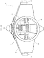
- Figures 21 , 22 illustrate a variant of the track assembly 9, in which the assembly 9 includes two track sections 60, 61, with which two hulls 62 are associated, rotatably supported about a longitudinal axis by a central section 63 of the track assembly connected to the coupling member 18, and controlled in position by an electric drive motor (not illustrated).
- the assembly 9 includes two track sections 60, 61, with which two hulls 62 are associated, rotatably supported about a longitudinal axis by a central section 63 of the track assembly connected to the coupling member 18, and controlled in position by an electric drive motor (not illustrated).
- two hulls 62 are arranged above the two track sections 60, 61, and serve as covers.
- the hulls 62 can be rotated by 180° until they reach the position shown in Figure 22 , in which they form a floating body that allows the vehicle to move rapidly over the water, as a hydrofoil.
- the vehicle can be configured with wheels, decoupling each track assembly 9 from the respective articulated leg and replacing it with an assembly of similar configuration, but provided with wheels instead of tracks, at least one of said wheels being motorized.
- Figure 23 shows the replacement of a track assembly 9 with a wheel assembly 9', which has a platform 19' also provided with a coupling pin 20', provided with a widened head 20a', for quick coupling with the jaws 21 of the quick coupling device of which the leg 8 is equipped.
- the platform 19' carries a supporting structure of twin front wheels RA and twin rear wheels RP.
- the structure supporting the front wheels RA is rotatably mounted about a vertical axis 191 on an upper support 190 rigidly connected to the platform 19'.
- An electric motor (not illustrated) is associated with the support 190 for controlling the steering of the equipment of the front wheels RA about the vertical axis 191.
Description
- The present invention relates to vehicles of the high mobility ATV ("All-Terrain Vehicle") type, usable, for example, in emergency and rescue civil activities, or in the agricultural field, or in earth-moving activities or the like. In one aspect, the invention is also applicable to the field of amphibious vehicles.
- Various types of vehicles of the type indicated above have been proposed in the past. None of the vehicles proposed up to now, however, can effectively solve the problem of an intervention in areas that are extremely difficult to reach, for example, in the case of emergency situations following natural disasters such as earthquakes, landslides and floods. A vehicle according to the preamble of
claim 1 is known fromUS 2011/236129 A1 . Other solutions are known fromUS 3 970 405 A andWO 2014/182216 A1 . - The object of the present invention is to produce a vehicle that is able to optimally satisfy the need indicated above.
- Another object of the invention is to achieve the aforesaid objective with a vehicle whose configuration is rapidly adaptable to any specific use.
- A further object is to provide a vehicle of the type specified above that combines the characteristics of a high-mobility vehicle with those of a vehicle with a high capacity for loading people and/or material, also equipped with a high efficiency propulsion system.
- An additional object is to provide a vehicle that can also be configured as an amphibious vehicle and arranged to easily advance in hostile environments, preserving the safety of the occupants of the vehicle.
- A further object is to provide a vehicle of the type indicated above that allows the occupants to perform operations on the ground, for example, operations to displace boulders and debris or excavations in the snow, allowing the operators to remain inside the vehicle.
- In view of achieving the aforesaid objects, the present invention relates to a high mobility all-terrain vehicle, comprising the features of
claim 1. - According to a further preferred characteristic, the aforesaid second end of each articulated leg is connected to the respective track assembly by means of a quick coupling device, which allows easy replacement of each track assembly with a wheel assembly, in order to reconfigure the vehicle as a vehicle on wheels.
- In a preferred embodiment, the structure of the vehicle comprises a front module, provided with the aforesaid front legs, and a rear module provided with the aforesaid rear legs. The front module and the rear module are connected in an articulated manner about a single longitudinal axis.
- According to a further preferred characteristic, the vehicle is provided at the front with at least two robotized manipulator arms having several articulation axes and/or telescopic arms terminating with working tools, for example, in the form of grippers, or support members for snow turbines, snowploughs, excavation blades or shovels and the like.
- According to another preferred characteristic, the vehicle structure is configured as a floating hull and the vehicle is, therefore, suitable for use as an amphibious vehicle configured to operate both on land and in water, in this second case using hydrojet propulsion.
- The vehicle according to the invention is preferably a large vehicle, with articulated legs that have a maximum extension in the order of 2-3 m.
- Thanks to the articulated legs and the various degrees of freedom with which they are equipped, the vehicle can easily advance on terrains with a degree of extreme difficulty, and is able to cross water courses with the track assemblies advancing on the bottom of the water course, while the structure of the vehicle remains above the water surface, exploiting the maximum extension of the articulated legs.
- In a preferred embodiment, the vehicle is equipped with a system of sensors associated with at least some of said articulated legs, suitable for detecting the contour of the ground in front of the vehicle during movement. An electronic control unit is configured to receive output signals from said sensor devices and to control the actuating devices associated with the articulated legs in order to automatically and dynamically adapt the attitude of the vehicle to the configuration of the ground detected by the aforesaid sensor devices, and also as a function of one or more operating parameters, including the speed of movement of the vehicle relative to the ground.
- More specifically, in this embodiment, the articulated legs of the vehicle serve both as the suspension function of the vehicle, and the function of allowing self-levelling of the vehicle while traveling on uneven terrain. The vehicle is associated with one or more sensor devices 100 (see
Figures 1 and20 ) in which adevice 100 is mounted above the driver's cabin), produced with any known technology, for example, "lidar" or radar or ultrasound laser detectors. Examples of sensor devices that can be used are the "TacFlir 280-HD" device by the company FLIR Systems, Inc., or the "Velodyne LiDAR" device of the company Velodyne LiDAR, Inc. It is also possible to associate a device of this type with each track assembly. The aforesaid devices are able to map the terrain in front of the vehicle according to a virtual path, for example, twice the width of each track assembly and of a maximum length not exceeding 30 m, for example. Said map, of three-dimensional configuration, is characterized by an altimetric profile of the longitudinal section and by an altimetric profile of the cross-section. The output signals from thesensors 100 are sent to the electronic control unit of which the vehicle is equipped, which consequently controls the actuators associated with each articulated leg. The electronic control unit is configured to control the actuators associated with the articulated legs of the vehicle both according to the output signals from thesensors 100 that define the contour of the terrain in front of the vehicle, and according to the advancing speed of the vehicle itself. The electronic control unit is thus able to control the actuators so that the articulated legs of the vehicle are arranged in an attitude that depends, according to a predetermined logic, on the contour of the terrain. For example, the articulated legs can be controlled so as to keep the vehicle cabin substantially at a constant level and with a stable horizontal attitude while the vehicle moves on the ground. Preferably, the electronic control system comprises an inertial platform that records the acceleration values along three mutually orthogonal axes and the rotations about said axes, and includes a control system programmed to preserve (or at least perturb to the minimum extent) the horizontal attitude of the entire body of the vehicle. The control system operates by comparing the output signals from thesensor system 100 with the movement limits of the articulated legs carrying the track assemblies of the vehicle. If, for example, the system detects that the compensation of the attitude is impossible as the stroke bottom of one the segments forming the articulated legs of the vehicle has been reached, the motion of the vehicle is instructed to stop, or slow down, up to a minimum value allowed. As can be seen, therefore, the vehicle control system is able to operate according to a predictive logic that allows the vehicle suspension system to operate non-passively as a result of the received stresses, but actively, thanks to a prediction of future stresses. It should also be noted that the maximum speed that can be reached by the vehicle with respect to the ground, in a control mode of the type indicated above, is limited by the need to allow thesensors 100 to detect the contour of the ground in front of the vehicle. The distance of 30 m - indicated above - for the range of action of thesensors 100 is not random. If it is hypothesized that the reaction time of the movement system of the single wheel is in the order of 1 second, with a sampling time of thesensors 100 of 0.001 seconds, then the maximum speed that can be reached by the vehicle is 108 Km/h (30 x 3600). This speed is fully adequate for all-terrain vehicles of the type forming the subject of the present invention. Of course, the above is also valid if wheel assemblies are mounted to replace the track assemblies. - Again, in the case of a preferred embodiment, each track assembly comprises a supporting structure including two parallel and spaced-apart side walls, rigidly connected to each other, an electric motor for actuating the track, having an inner stator and an outer rotor surrounding the stator, the stator of the electric motor being rigidly connected to a stationary shaft, having ends projecting from opposite sides of the electric motor and rigidly connected to said side walls of the track assembly, close to the front end of the track assembly. The rotor of the electric motor is rotatably connected with at least one front wheel for dragging the track, arranged coaxially with said rotor. A closed-loop track is engaged about said at least one front wheel driven by the electric motor, about at least one rear wheel freely rotatably mounted on said supporting structure at the rear end of the track assembly, as well as on a set of freely rotatable wheels carried by said supporting structure on each side of the track assembly. Preferably, a set of upper wheels, freely rotatably mounted, each on a respective side wall of the track assembly, and a set of lower wheels, each of which are vertically pivoting from the respective side wall of the track assembly, is provided.
- Further characteristics and advantages of the invention are indicated in the attached claims.
- The present invention will now be described with reference to the attached drawings, provided purely by way of non-limiting example, in which:
-
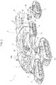
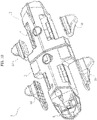
Figure 1 is a perspective view of an embodiment example of the vehicle according to the invention, -
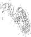
Figure 2 is a perspective view on an enlarged scale of an articulated leg of the vehicle ofFigure 1 , provided with the respective track assembly, -
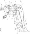
Figure 3 is an additional perspective view of the articulated leg and of the respective track assembly, in a different relative position, -
Figure 4 is an additional partially cross-sectioned perspective view of the articulated leg and of the track assembly, -
Figure 5 is an enlarged scale view of a detail of the connection between the articulated leg and the vehicle structure, -
Figure 6 is a partially cross-sectioned perspective view of the detail of the connection between the articulated leg and the track assembly, -
Figure 7 is a perspective view from below showing the quick connection device, for coupling the lower end of the articulated leg with the track assembly, -
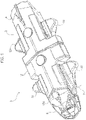
Figure 8 is a partially cross-sectioned perspective view of the detail of the front end of the track assembly, -
Figure 9 is a perspective view from above of the vehicle body, devoid of articulated legs, -
Figure 10 is an exploded perspective view of the body ofFigure 9 , -
Figure 11 is a perspective view from below of the vehicle ofFigure 1 , -
Figure 12 is a side view of the vehicle ofFigure 1 , -
Figures 13 and14 are side views on an enlarged scale of the front end of the vehicle, in two different operating conditions of the nose of the body, -
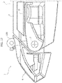
Figure 15 is a perspective view of the front module of the vehicle ofFigure 1 , -
Figure 16 is a rear perspective view of the module ofFigure 15 , -
Figure 17 is an additional cross-sectioned perspective view of the vehicle according to the invention, -
Figures 18 and19 are perspective views that illustrate a manipulator arm, of which the vehicle of the invention is provided, in two different operating conditions, -
Figure 20 illustrates the vehicle according to the invention in a variant ofFigure 1 , and -
Figures 21 and22 show a variant of the track assembly in two different operating conditions, and -
Figure 23 is a perspective view of an articulatedleg 8, showing the replacement of atrack assembly 9 with a wheel assembly 9'. - The drawings refer to examples, provided herein by way of non-limiting example, of some preferred embodiments of the invention. With reference to
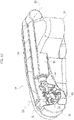
Figure 1 ,numeral 1 indicates - in its entirety - a high-mobility, large-scale ATV, designed to operate on terrains of extreme difficulty in emergency and rescue activities. The vehicle comprises abody 2 including afront module 3 and a rear module 4 freely articulated to each other about a single longitudinal axis 5 (seeFigure 12 ). The vehicle is provided with afront driving cabin 6, which in the preferred embodiment, is pivotably mounted on the front end of thefront module 3 between a normal cruising position, illustrated inFigures 1 and12 ,13 , and a position rotated downwards (seeFigure 14 ) in which the crew involved in the maneuvers maintain full visibility on the ground in front of the vehicle even when the vehicle assumes a strongly inclined upward attitude. InFigure 14 , thereference number 7 indicates the articulation axis of the supporting structure of the drivingcabin 6 with respect to the structure of thefront module 3. The position of the drivingcabin 6 about theaxis 7 is controlled by an electric or fluid actuator (not shown) of any known type. Returning toFigure 1 , thevehicle 1, in the embodiment illustrated herein by way of example, is equipped with four articulated legs 8: two front legs, connected in an articulated manner to thefront module 3 of the body, and two rear legs, connected in an articulated manner to the rear module 4 of the body. Each articulated leg has a first end portion articulated to the vehicle structure, and a second end portion connected in an articulated manner to arespective track assembly 9, the structure of which will be illustrated in detail below. - Referring now to
Figure 2 , each articulatedleg 8 has, in the embodiment described herein, a single segment connected in an articulated manner at its ends to the vehicle structure and to the respective track assembly. However, the case in which each articulatedleg 8 is constituted by two or more segments articulated to each other in series is by no means excluded. - With reference to
Figure 2 and also toFigures 9 and10 , the articulatedlegs 8 are connected to four modules 10 (Figure 10 ) removably connected by means of coupling devices of any known type (not illustrated) to the two sides of thefront module 3 and the rear module 4 of thevehicle body 2. - Referring now in particular to
Figure 5 , eachmodule 10, rigidly connected to the vehicle structure, supports anintermediate support member 12 in a freely rotatable manner about afirst axis 11, vertically directed with respect to the vehicle structure. The structure of theleg 8 is, in turn, connected in an articulated manner to theintermediate support 12 about asecond axis 13 directed orthogonally with respect to thefirst axis 11. - An electric or fluid actuator device of any known type is associated with the
first axis 11, for controlling a rotation of theintermediate support 12 about thefirst axis 11. In the example illustrated in the drawings, the actuator device associated with thefirst axis 11 comprises twocylinders 14, electrically- or fluidly-operated, each having a body carried by the fixed structure of the vehicle and astem 14a connected in an articulated manner to arespective ear 15 of theintermediate support 12. The illustrated example shows the use of twoactuator cylinders 14, with the object of providing a greater actuating power, but it is, however, evident that the actuator device could comprise a single actuator cylinder, or be formed of any other type of actuator, for example, an electric motor connected by means of a transmission of gears to a shaft rigidly connected to theintermediate support 12. - In a similar manner, the rotation of the articulated
leg 8 about thesecond axis 13 is controlled by an actuator device of any known type, which in the illustrated case takes the form of two actuatingcylinders 16 each having anend 16a articulated to theintermediate support 12 and, on the opposite side, astem 16b having anend 16c articulated to the structure of theleg 8. - The
actuator devices legs 8 are controlled by one or more electronic control units of which the vehicle is provided, as a function of signals imparted manually by the driver-operator and/or also, in an automatic driving mode, as a function of signals emitted by sensors associated with the vehicle structure and/or articulated legs, and configured to detect the terrain contour in front of the vehicle. In this automatic driving control mode, the electronic control unit can be programmed to vary the attitude of the articulated legs and also, as will be seen below, of the track assemblies that they carry, as a function of the signals emitted by the detection sensors of the terrain contour and according to a series of further operating parameters of the vehicle, including in particular the speed of movement of the vehicle relative to the ground. - The actuating device associated with the
first axis 11 controls the angular position of the entire articulatedleg 8 with respect to theaforesaid axis 11, and consequently the track width distance of therespective track assembly 9 with respect to the median longitudinal plane of the vehicle. As shown below, when the track width varies between the two front track assemblies or the two rear track assemblies, each track assembly can be rotated about a vertical axis with respect to the corresponding end of the articulated leg, to maintain a parallel attitude to the aforesaid longitudinal median plane. The actuatingcylinders 16 instead control the angular position of theleg 8 about thehorizontal axis 13 and, consequently, the vertical distance between each track assembly and themodule 10 of the vehicle structure to which the respective articulated leg is connected. For example,Figure 2 shows a vertically extended attitude of the articulatedleg 8, in which the vehicle is maintained at a greater height with respect to the track assembly.Figure 1 instead shows a lowered attitude of thebody 2 of the vehicle, in which thelegs 8 extend substantially in a horizontal longitudinal direction. In order to avoid interference between the two legs on each side of the vehicle in this condition, the articulatedlegs 8 arranged on each side of the vehicle are directed in opposite directions, starting from the respective articulation axes 13. More precisely, eachfront leg 8, in the horizontally extended configuration, is directed forwards from therespective axis 13, while eachrear leg 8 is directed backwards, starting from therespective axis 13. - With reference now in particular to
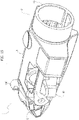
Figure 6 , each articulatedleg 8 has its end that is distal relative to the structure of the vehicle articulated about athird axis 17 to acoupling member 18, for quick coupling with arespective track assembly 9. Thethird axis 17 is a horizontal axis parallel to thesecond axis 13. In the embodiment illustrated here, the articulation of thecoupling member 18 to theleg 8 about thethird axis 17 is a freely rotatable articulation, which allows thetrack assembly 9 to have a pitching-free oscillation, about theaxis 17, while the vehicle is moving, which allows thetrack assembly 9 to adapt to the contour of the terrain on which the vehicle proceeds. However, an embodiment in which theaxis 17 is a controlled axis is not excluded. - The
coupling member 18 is designed to couple with aplatform 19 which supports thetrack assembly 9. To this end, thesupport platform 19 has acoupling pin 20 projecting upwards and terminating with anend bulb 20a (Figure 3 ), of enlarged diameter, arranged to be gripped between a plurality of gripping jaws 21 (Figure 7 ) carried by thecoupling member 18. Thejaws 21 are movable radially onguide tracks 22 carried by thecoupling member 18 between a radially outer position, for releasing thecoupling pin 20, and a radially inner position for retaining thecoupling pin 20. In this coupling position, thepin 20 is, however, free to rotate about its axis with respect to theplatform 19. Moreover, in this coupling position, theentire support platform 19 is rotatably supported by thecoupling member 18 about afourth axis 23, vertically directed, by means of a rollingbearing 24. In this way, theentire track assembly 9 carried by thesupport platform 19 is able to rotate about thefourth axis 23 with respect to thecoupling member 18. This rotation is controlled by amotor 24, for example, hydraulic or electric, which controls the rotation of apinion 25 engaging with agear 26, carried by thesupport platform 19, having an inner set of teeth concentric with theaxis 23. - Again with reference to
Figure 2, to Figure 3 and toFigure 6 , thetrack assembly 9 has a supporting structure that is articulated to thesupport platform 19 about afifth axis 27. To this end, in the embodiment illustrated herein, thesupport platform 19 has two articulation pins 28, aligned with each other, directed longitudinally and projecting anteriorly and posteriorly from thesupport platform 19, respectively, (Figure 6 shows the front pin 28). The articulation pins 28 are rotatably received withinbushings 29 carried by the supporting structure of thetrack assembly 9. In this way, the entire structure of thetrack assembly 9 is free to oscillate about thelongitudinal axis 27. Again in the case of the embodiment illustrated herein, the oscillation of thetrack assembly 9 about thelongitudinal axis 27 is opposed by two pairs of shock-absorbing fluid cylinders 30 (only one of which is visible inFigure 6 ). Each shock-absorbingcylinder 30 has an end articulated to a side of thesupport platform 19 and the opposite end articulated to the supporting structure of thetrack assembly 9. - With reference now, in particular, to
Figures 4 and8 , the supporting structure of thetrack assembly 9, indicated - in its entirety - by thereference number 31, comprises anupper wall 32, carrying thebushing 29 for the articulated connection about thelongitudinal axis 27, and twoside walls 33 parallel to each other and spaced apart. At the front end of thetrack assembly 9, the twoside walls 33 are rigidly connected to each other by means of a stationarytubular shaft 34. - The
shaft 34 axially crosses anelectric motor 35 for driving the track assembly. Theelectric motor 35 has aninner stator 36, rigidly connected to theshaft 34, and anouter rotor 37, surrounding thestator 36. Tworotating wheels 38 for driving the track, rotatably connected above the portions of theshaft 34 that protrude from opposite sides of theelectric motor 35, are rotatably connected with therotor 37 of theelectric motor 35. - The
track assembly 9 comprises a closed-loop track 39 of elastomeric material, engaged both above thefront driving wheels 38, and above tworear wheels 40 freely rotatably mounted on theside walls 33 of the supporting structure of thetrack assembly 9, at the rear end of thetrack assembly 9, and about two sets ofwheels 41, 42, freely rotatably mounted on both sides of the track assembly. More precisely, eachside wall 33 of the supporting structure of thetrack assembly 9 carries a first upper set of wheels 41, freely rotatably mounted on therespective wall 33, as well as a second lower set ofwheels 42, which are each rotatably mounted on awheel support 43 connected to therespective side wall 33 of the supporting structure of thetrack assembly 9 by means of a suspension system, including, in the illustrated example, a shock-absorbingcylinder 44. In this way, each of thewheels 32 of the lower set of wheels of the track assembly is free to oscillate vertically, following the unevenness of the ground. - All the
wheels drive wheels 38, and possibly also therear wheels 40, or the two sets ofside wheels 41, 42 can have any known configuration to ensure their correct engagement with the inner surface of thetrack 39. For example, thetrack 39 can have a profiled inner surface for engaging a set of teeth of the drivingwheels 38. - Referring now to
Figures 15 ,16 , the articulated connection about the longitudinal axis 5 between thefront module 3 and the rear module 4 of the vehicle is obtained by means of a rolling bearing (not shown in the drawings) interposed between atubular opening 45 protruding from the rear wall of thefront module 3 and a corresponding tubular opening (not shown) protruding from the front wall of the rear module 4. In the connected condition, the two tubular openings, rotatably mounted with respect to each other, constitute a communication corridor between the inner spaces of the front andrear modules 3, 4.Figure 16 shows an example of the arrangement of the space inside thefront module 3. It is evident that these modules can be arranged to accommodate personnel and equipment or to act as a hold, according to the needs of each specific application. -
Figure 17 shows the twotubular openings internal combustion engine 47 which is associated with the rear module 4. - In the embodiment that is illustrated here, the internal combustion engine of which the vehicle is provided is designed solely to drive, by means of a
transmission belt 48, the shaft of a battery ofelectric generators 49 that supplies the entire vehicle with electrical power. Theinternal combustion engine 7 can have any known configuration, optimized to reduce consumption and harmful exhaust emissions. - When driving the vehicle, the driving action is entrusted solely to the
electric motors 35 associated with thetrack assemblies 9. These motors are driven by the battery ofgenerators 49, which are connected to the generators by means of cables passing through an inner passage formed in each articulatedleg 8, and in the structure of therespective track assembly 9. The vehicle is equipped with one or more electronic control units that manage the power supply of the advancementelectric motors 35, as well as the actuation of all the actuators described above associated with each articulated leg and the respective track assembly. - During advancement on the ground, the articulated legs rotate about the respective articulation axes 11, 13 to modify the height of the vehicle structure with respect to each track assembly and to change the track width distance between each pair of track assemblies, depending on the characteristics of the terrain. Furthermore, during the advancement on the ground, each track assembly oscillates about the
transverse axis 17 and about thelongitudinal axis 27 to adapt to the terrain configuration. As the track varies, eachtrack assembly 9 is controlled in the position about thevertical axis 23 to keep it oriented in the direction of travel. - According to a further preferred characteristic, two
robotized manipulator arms 50 are provided on the two sides of thefront module 3 of the vehicle (seeFigures 1 ,18 ,19 ). Eachrobotized manipulator arm 50 comprises a fixedstructure 51, rigidly connected to the vehicle structure, abase member 52 rotatably mounted about atransverse axis 53 on the fixedstructure 51, afirst arm element 54 rotatably mounted on thebase member 52 about anaxis 54 orthogonal to theaxis 53, and asecond arm element 55 articulated to thefirst arm element 54 about anaxis 56 parallel to theaxis 54. Thesecond arm element 55 carries atelescopic stem 56 terminating with amaneuvering tool 57, which in the illustrated example comprises twogripping jaws 58 operated by means of a gear transmission by one or more electric actuators. More generally, the manipulator arms can carry, in a replaceable manner, any type of maneuvering tools, or for example, support members for snow turbines, snowploughs, excavation blades or shovels and the like. - The axial sliding movement of the
telescopic stem 56 and the rotation movements about theaxes -
Figure 18 shows therobotized arm 50 in a partially extended condition, whileFigure 19 shows thearm 50 in the folded rest condition. -
Figure 20 shows a variant of the vehicle ofFigure 1 , with manipulator arms in a relaxed condition. - As is evident from the preceding description, the vehicle according to the invention can be configured to be used only on land, without prejudice to the possibility of crossing water courses with the
track assemblies 9 advancing on the bottom of the water course, while the body of the vehicle is kept above the water surface, thanks to an extended configuration of the articulatedlegs 8. The vehicle is designed to be produced in particular with large dimensions, with articulated legs that - in the extended condition - reach a length in the order of 2-3 m. - However, in the preferred embodiment, the vehicle according to the invention is arranged for being used as an amphibious vehicle or even as an underwater vehicle. In the preferred embodiment, the body of the front and
rear modules 3, 4 constitutes a hull configured to float or move underwater and anozzle 59 is provided below the rear module 4 for emitting a water jet. -
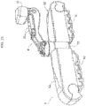
Figures 21 ,22 illustrate a variant of thetrack assembly 9, in which theassembly 9 includes twotrack sections hulls 62 are associated, rotatably supported about a longitudinal axis by acentral section 63 of the track assembly connected to thecoupling member 18, and controlled in position by an electric drive motor (not illustrated). In the advancing configuration on the ground (Figure 21 ), twohulls 62 are arranged above the twotrack sections hulls 62 can be rotated by 180° until they reach the position shown inFigure 22 , in which they form a floating body that allows the vehicle to move rapidly over the water, as a hydrofoil. - For the mass on the ground, the vehicle can be configured with wheels, decoupling each
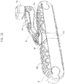
track assembly 9 from the respective articulated leg and replacing it with an assembly of similar configuration, but provided with wheels instead of tracks, at least one of said wheels being motorized.Figure 23 shows the replacement of atrack assembly 9 with a wheel assembly 9', which has a platform 19' also provided with a coupling pin 20', provided with awidened head 20a', for quick coupling with thejaws 21 of the quick coupling device of which theleg 8 is equipped. The platform 19' carries a supporting structure of twin front wheels RA and twin rear wheels RP. In one embodiment, the structure supporting the front wheels RA is rotatably mounted about a vertical axis 191 on anupper support 190 rigidly connected to the platform 19'. An electric motor (not illustrated) is associated with thesupport 190 for controlling the steering of the equipment of the front wheels RA about the vertical axis 191. - Of course, without prejudice to the principle of the invention, the details of construction and the embodiments may vary widely with respect to those described and illustrated purely by way of example, without departing from the scope of the present invention.
Claims (14)
- A high mobility all-terrain vehicle (ATV), in particular for emergency and rescue civil activities or for activities in the agricultural field or earth-moving activities, comprising:- a vehicle structure (2), comprising at least one module (3,4) for transporting persons and/or material,- at least two front legs (8) and at least two rear legs (8) articulated to the vehicle structure (2) and carrying respective track assemblies (9), wherein further:- each track assembly (9) carries a respective electric motor (35) for actuating the track (39),- each of said articulated front and rear legs (8) comprises one or more articulated segments (8), and has a first end portion articulated to the vehicle structure (2) and a second end portion articulated to the respective track assembly (9),- the aforesaid first end portion of each leg (8) is connected in an articulated manner to the vehicle structure (2) about a first axis (11), directed vertically with respect to the vehicle structure (2),- an actuator device (14) for rotating the leg (8) about said first axis is associated with said first axis (11), which can be actuated to vary the position of the leg (8) about said first axis (11) and to consequently vary the track width distance of the respective track assembly (9) with respect to the median longitudinal plane of the vehicle structure (2),- the aforesaid second end portion of each leg (8) is connected in an articulated manner to a supporting structure (31) of the respective track assembly (9), both about a third axis (17), horizontally directed, and about a fourth axis (23), vertically directed,- the articulation of the track assembly (9) about said third horizontal axis (17) is preferably a freely rotatable articulation, which allows the track assembly (9) to engage in a pitching-free movement to follow the contour of the ground while the vehicle is moving,- an actuator device (24) for rotating the track assembly about said fourth axis (23) is associated with said fourth axis (23), which can be actuated to vary the position of the track assembly (9) about said fourth axis (23), for example, to maintain the track assembly (9) parallel to the vertical longitudinal plane of the vehicle structure (2) when the track width distance of the track assembly (9) with respect to the aforesaid median plane is varied,
said vehicle being characterized in that:- said first end portion of each leg (8) is connected in an articulated manner to the vehicle structure (2) both about said first axis (11), directed vertically with respect to the vehicle structure (2), and about a second axis (13), directed horizontally with respect to the vehicle structure (2),- an actuator device (16) for rotating the leg (8) about said second axis (13) is associated with said second axis (13), which can be actuated to vary the position of the leg (8) about said second axis (13) to vary accordingly the height of the vehicle structure (2) with respect to the track assembly (9) carried by said leg (8),- said second end portion of each leg (8) is connected in an articulated manner to said supporting structure (31) of the respective track assembly (9) also about a fifth axis (27), directed parallel to the longitudinal direction of the track assembly (9),- the articulation of the track assembly (9) about said fifth longitudinal axis (27) is a freely rotatable articulation, or an articulation with which one or more shock-absorbing devices (30) are associated, or an articulation controlled by a respective actuator device. - A vehicle according to claim 1, characterized in that it is provided with at least two robotic manipulator arms (50) carried by the structure (2) of the vehicle adjacent to the front end of the vehicle and provided with work tools, for example, in the form of gripping pliers, or support members for snow turbines, snowploughs, and excavation blades or shovels.
- A vehicle according to claim 1, characterized in that each track assembly comprises:- a supporting structure (31) including two parallel and spaced apart side walls (33), rigidly connected to each other,- an electric motor (35) for driving the track (39), having an inner stator (36) and an outer rotor (37) surrounding the stator (36), the stator (36) being rigidly connected to a stationary shaft (34), having ends projecting from opposite sides of the electric motor (35) and rigidly connected to said side walls (33) of the supporting structure (31) of the track assembly, near the front end of the track assembly (9), said rotor (37) being rotatably connected with at least one front wheel (38) for dragging the track (39), arranged coaxially with said rotor (37),- a closed-loop track (39) engaging about said at least one front wheel (38) for dragging the track (39), about at least one rear wheel (40) freely rotatably mounted on said supporting structure (31) of the track assembly (9) near the rear end of the track assembly (9), and on a set of freely rotatable wheels (41, 42) carried by said supporting structure (31) on each side of the track assembly (9).
- A vehicle according to claim 1, characterized in that the aforesaid first end of each leg (8) is mounted articulated about said second axis (13) on an intermediate support (12), which is mounted articulated about said first axis (11) on a support module (10), rigidly connected, in a removable manner, to one side of the vehicle structure (2).
- A vehicle according to claim 1, characterized in that the supporting structure (31) of each track assembly (9) is mounted articulated about said fifth longitudinal axis (27) on a support platform (19), and in that said support platform (19) is rotatably mounted about said fourth vertical axis (23) on a coupling member (18) which is, in turn, mounted articulated about said third horizontal axis (17) on the aforesaid second end of the respective articulated leg (8), and
in that said support platform (19) is retained on said coupling member (18) by a quick-release coupling device (20, 20a, 21). - A vehicle according to claim 5, characterized in that said quick-release coupling device comprises a coupling pin (20) projecting axially upwards from said support platform (19), and rotatable thereto, and a plurality of gripping jaws (21) movable radially on guides (22) carried by said coupling member (18) and movable between a radially outer release position, and a radially inner position, in which said gripping jaws (21) axially retain an end bulb (20a) of said coupling pin (20), leaving said pin (20) free to rotate with respect to said support platform (19) about said fourth axis (23).
- A vehicle according to claim 5, characterized in that the vehicle is reconfigurable with wheel assemblies in place of the aforesaid track assemblies (9), each wheel unit being configured to be coupled to a respective articulated leg (8) by means of said quick coupling device.
- A vehicle according to claim 1, characterized in that it is equipped with one or more electronic control units, for controlling the actuator devices associated with the aforesaid articulation axes of each articulated leg (8).
- A vehicle according to claim 1, characterized in that it is provided with sensors for detecting the terrain contour in front of the vehicle, and in that one or more electronic control units are programmed to control the aforesaid actuator devices associated with the articulation axes of the legs (8) of the vehicle according to the output signals of said sensors, as well as according to one or more operating parameters of the vehicle, including the forward speed of the vehicle with respect to the ground.
- A vehicle according to claim 1, characterized in that it is equipped with an internal combustion engine used solely to drive an assembly of one or more electric generators (49) for powering the electric motors (35) for driving the track assemblies (9) and for powering the electric actuators, and all on-board vehicle services that are electrically operated.
- A vehicle according to claim 1, characterized in that the vehicle structure comprises a front module (3) and a rear module (4) connected in a mutually articulated way about a longitudinal axis (5).
- A vehicle according to claim 1, characterized in that it comprises a driving cabin (6) connected to the vehicle structure (2) in a rotatable manner about a transverse axis (7), the driving cabin (6) being thus configured to be rotated downwards to allow full visibility of the ground in front of the vehicle when the vehicle takes on a very inclined upward attitude.
- A vehicle according to claim 1, characterized in that the vehicle structure (2) is configured as a hull suitable for floating and/or moving underwater, to allow an amphibious and/or underwater use of the vehicle, said structure (2) being equipped below with a nozzle (59) for the emission of a waterjet.
- A vehicle according to claim 13, characterized in that each track assembly (9) is equipped with a covering structure (62) rotatable below the track to act as a floating hull, like a hydrofoil skid.
Applications Claiming Priority (2)
| Application Number | Priority Date | Filing Date | Title |
|---|---|---|---|
| IT102017000032682A IT201700032682A1 (en) | 2017-03-24 | 2017-03-24 | HIGH-MOBILITY ATV VEHICLE, FOR USE, FOR EXAMPLE, IN CIVIL EMERGENCY AND RESCUE ACTIVITIES, IN AGRICULTURAL FIELD OR IN EARTH MOVEMENT ACTIVITY |
| PCT/IB2018/051899 WO2018172956A1 (en) | 2017-03-24 | 2018-03-21 | High mobility all-terrain-vehicle (atv), for example for emergency and rescue civil activities or for activities in the agricultural field or for earth-moving activities |
Publications (2)
| Publication Number | Publication Date |
|---|---|
| EP3601023A1 EP3601023A1 (en) | 2020-02-05 |
| EP3601023B1 true EP3601023B1 (en) | 2022-04-13 |
Family
ID=59700016
Family Applications (1)
| Application Number | Title | Priority Date | Filing Date |
|---|---|---|---|
| EP18717698.7A Active EP3601023B1 (en) | 2017-03-24 | 2018-03-21 | High mobility all-terrain-vehicle (atv), for example for emergency and rescue civil activities or for activities in the agricultural field or for earth-moving activities |
Country Status (5)
| Country | Link |
|---|---|
| US (1) | US10967690B2 (en) |
| EP (1) | EP3601023B1 (en) |
| CN (1) | CN110446651B (en) |
| IT (1) | IT201700032682A1 (en) |
| WO (1) | WO2018172956A1 (en) |
Families Citing this family (7)
| Publication number | Priority date | Publication date | Assignee | Title |
|---|---|---|---|---|
| CA3110617A1 (en) * | 2018-09-07 | 2020-03-12 | Soucy International Inc. | Track system |
| CN109515538B (en) * | 2018-12-29 | 2023-05-30 | 中国科学院沈阳自动化研究所 | Reconfigurable joint crawler composite mobile robot |
| US11958192B2 (en) * | 2019-05-31 | 2024-04-16 | Amir Khajepour | Method and system for mobile reconfigurable robot for a large workspace |
| EP3808510A1 (en) * | 2019-10-16 | 2021-04-21 | Everis Aeroespacial y Defensa, S.L.U. | Tele-commanded robot |
| CN111515917A (en) * | 2020-05-07 | 2020-08-11 | 中自机器人技术(安庆)有限公司 | Robot for inspecting underground pipeline |
| CN113816318A (en) * | 2021-09-17 | 2021-12-21 | 上海东方航空设备制造有限公司 | Novel high altitude construction device automatic leveling system |
| CN114408104B (en) * | 2022-01-18 | 2023-09-08 | 北京世航华远科技有限公司 | Stranding-prevention unmanned ship for mapping complex water area environment and use method thereof |
Family Cites Families (26)
| Publication number | Priority date | Publication date | Assignee | Title |
|---|---|---|---|---|
| US3664448A (en) * | 1970-05-06 | 1972-05-23 | Rex Chainbelt Inc | Vehicle for carrying agricultural or construction tools and the like |
| US3792745A (en) * | 1972-03-10 | 1974-02-19 | Rexnord Inc | Steering system for tool-carrying vehicle |
| US3900077A (en) * | 1974-04-03 | 1975-08-19 | Caterpillar Tractor Co | Vehicle for surf zone work |
| US3970405A (en) * | 1974-05-03 | 1976-07-20 | Cmi Corporation | Slipform paving apparatus |
| DE2807518C3 (en) * | 1978-02-22 | 1981-09-24 | Habegger, Willy, Hünibach | Wheel suspension for a traveling and walking gear |
| US4558758A (en) * | 1983-12-02 | 1985-12-17 | Erwin Littman | Prime mover |
| US4823852A (en) * | 1987-02-05 | 1989-04-25 | Allied Systems Company | Tree feller-buncher |
| ITTO20010216A1 (en) * | 2001-03-09 | 2002-09-09 | Elasis Sistema Ricerca Fiat | TRACKED VEHICLE PROVIDED WITH OSCILLATING TRACKED CARRIAGES. |
| US6981461B1 (en) * | 2004-08-23 | 2006-01-03 | Burg Donald E | Amphibious high speed marine vehicle |
| CN101417674B (en) * | 2008-11-20 | 2010-05-12 | 太原理工大学 | Coal mine down-hole searching and detecting robot moving apparatus |
| DE102011014666B4 (en) * | 2010-03-26 | 2022-03-31 | Guntert & Zimmerman Const. Div. Inc. | Slipform paver and method for resetting a slipform paver |
| WO2013001502A2 (en) * | 2011-06-30 | 2013-01-03 | Dick Kyle | Improvements in or relating to a vessel |
| US20130000996A1 (en) * | 2011-06-30 | 2013-01-03 | Caterpillar Inc. | Mobile machine with a support system |
| CN102672701B (en) * | 2012-04-27 | 2014-09-17 | 华东交通大学 | Master-slave robot for high obstacle crossing and accurate bomb disposal and explosion elimination |
| CH707606A1 (en) * | 2013-02-05 | 2014-08-15 | Studersond Ag | Vehicle. |
| CN103158797B (en) * | 2013-03-07 | 2015-09-02 | 深圳市中南宏业高新技术有限公司 | Unmanned remote controlled heavy-duty work vehicles under water |
| SE538232C2 (en) * | 2013-05-08 | 2016-04-12 | BAE Systems Hägglunds Aktiebolag | Drive unit for tracked vehicles and vehicles equipped with drive unit |
| FI125426B (en) * | 2013-06-03 | 2015-10-15 | Ponsse Oyj | Arrangement and method for enabling rotation of a vehicle bogie or roller axle and chassis |
| US9541195B2 (en) * | 2013-09-24 | 2017-01-10 | Gomaco Corporation | Ratchet assembly and rotational sensor drive mechanism |
| WO2015079418A2 (en) * | 2013-11-28 | 2015-06-04 | Nicolaas Daniel Lombard Burger | Mining apparatus |
| US9764762B2 (en) * | 2014-05-13 | 2017-09-19 | Gomaco Corporation | Rotary pivot arm positioning assembly |
| US9388538B2 (en) * | 2014-06-09 | 2016-07-12 | Wirtgen Gmbh | Frame width adjustment by steering |
| JP6344668B2 (en) * | 2015-02-10 | 2018-06-20 | 国立研究開発法人宇宙航空研究開発機構 | Rough terrain vehicle |
| CN105128957B (en) * | 2015-09-13 | 2017-05-17 | 陈翡 | Crawler type explosive-handling robot |
| US9969427B1 (en) * | 2016-11-16 | 2018-05-15 | Wirtgen Gmbh | Transport conversion mode |
| CN109533082B (en) * | 2019-01-07 | 2023-09-22 | 太原科技大学 | Giant six-leg crawler foot polar region scientific vehicle |
-
2017
- 2017-03-24 IT IT102017000032682A patent/IT201700032682A1/en unknown
-
2018
- 2018-03-21 CN CN201880020796.3A patent/CN110446651B/en active Active
- 2018-03-21 EP EP18717698.7A patent/EP3601023B1/en active Active
- 2018-03-21 WO PCT/IB2018/051899 patent/WO2018172956A1/en active Application Filing
- 2018-03-21 US US16/087,893 patent/US10967690B2/en active Active
Non-Patent Citations (1)
| Title |
|---|
| None * |
Also Published As
| Publication number | Publication date |
|---|---|
| CN110446651B (en) | 2022-08-30 |
| US10967690B2 (en) | 2021-04-06 |
| US20200009931A1 (en) | 2020-01-09 |
| CN110446651A (en) | 2019-11-12 |
| WO2018172956A1 (en) | 2018-09-27 |
| IT201700032682A1 (en) | 2018-09-24 |
| EP3601023A1 (en) | 2020-02-05 |
Similar Documents
| Publication | Publication Date | Title |
|---|---|---|
| EP3601023B1 (en) | High mobility all-terrain-vehicle (atv), for example for emergency and rescue civil activities or for activities in the agricultural field or for earth-moving activities | |
| AU2017285709B2 (en) | Drive module | |
| US9919753B2 (en) | Robotic mobile low-profile transport vehicle | |
| EP2726256B1 (en) | Mobile robot | |
| US8540040B2 (en) | Multi-purpose ground vehicle | |
| JP5411702B2 (en) | Robotic endless track car with movable arm | |
| US8571711B2 (en) | Modular robotic crawler | |
| US6774597B1 (en) | Apparatus for obstacle traversion | |
| CN110667722B (en) | Wheel-foot switching robot based on electro-hydraulic hybrid drive and control system | |
| KR20010052261A (en) | Earth-based vehicle | |
| CN107650601B (en) | Tandem type hybrid power amphibious robot | |
| CN111846001B (en) | Wheel-leg variable-structure robot | |
| CN110341910B (en) | Underwater steel structure surface marine organism cleaning robot and panoramic imaging system thereof | |
| RU102583U1 (en) | TRACK VEHICLE WITH VARIABLE BASE | |
| JP2591531B2 (en) | A work vehicle that can handle uneven terrain | |
| CN213768780U (en) | Natural navigation AGV | |
| WO2023107081A1 (en) | Cave and urban area unmanned ground vehicle | |
| Tao et al. | A small wheeled robotic rover for planetary exploration | |
| Healy et al. | Sea-dragon: an amphibious robot for operation in the littorals | |
| Easter et al. | Mobility study for a Lunar rover | |
| PL190386B1 (en) | Crawler-type running gear, in particular that for a mobile robot | |
| MXPA00010154A (en) | Earth-based vehicle |
Legal Events
| Date | Code | Title | Description |
|---|---|---|---|
| STAA | Information on the status of an ep patent application or granted ep patent |
Free format text: STATUS: UNKNOWN |
|
| STAA | Information on the status of an ep patent application or granted ep patent |
Free format text: STATUS: THE INTERNATIONAL PUBLICATION HAS BEEN MADE |
|
| PUAI | Public reference made under article 153(3) epc to a published international application that has entered the european phase |
Free format text: ORIGINAL CODE: 0009012 |
|
| STAA | Information on the status of an ep patent application or granted ep patent |
Free format text: STATUS: REQUEST FOR EXAMINATION WAS MADE |
|
| 17P | Request for examination filed |
Effective date: 20190730 |
|
| AK | Designated contracting states |
Kind code of ref document: A1 Designated state(s): AL AT BE BG CH CY CZ DE DK EE ES FI FR GB GR HR HU IE IS IT LI LT LU LV MC MK MT NL NO PL PT RO RS SE SI SK SM TR |
|
| AX | Request for extension of the european patent |
Extension state: BA ME |
|
| DAV | Request for validation of the european patent (deleted) | ||
| DAX | Request for extension of the european patent (deleted) | ||
| STAA | Information on the status of an ep patent application or granted ep patent |
Free format text: STATUS: EXAMINATION IS IN PROGRESS |
|
| 17Q | First examination report despatched |
Effective date: 20201119 |
|
| GRAP | Despatch of communication of intention to grant a patent |
Free format text: ORIGINAL CODE: EPIDOSNIGR1 |
|
| STAA | Information on the status of an ep patent application or granted ep patent |
Free format text: STATUS: GRANT OF PATENT IS INTENDED |
|
| INTG | Intention to grant announced |
Effective date: 20211111 |
|
| GRAS | Grant fee paid |
Free format text: ORIGINAL CODE: EPIDOSNIGR3 |
|
| GRAA | (expected) grant |
Free format text: ORIGINAL CODE: 0009210 |
|
| STAA | Information on the status of an ep patent application or granted ep patent |
Free format text: STATUS: THE PATENT HAS BEEN GRANTED |
|
| AK | Designated contracting states |
Kind code of ref document: B1 Designated state(s): AL AT BE BG CH CY CZ DE DK EE ES FI FR GB GR HR HU IE IS IT LI LT LU LV MC MK MT NL NO PL PT RO RS SE SI SK SM TR |
|
| REG | Reference to a national code |
Ref country code: GB Ref legal event code: FG4D |
|
| REG | Reference to a national code |
Ref country code: CH Ref legal event code: EP |
|
| REG | Reference to a national code |
Ref country code: DE Ref legal event code: R096 Ref document number: 602018033743 Country of ref document: DE |
|
| REG | Reference to a national code |
Ref country code: IE Ref legal event code: FG4D |
|
| REG | Reference to a national code |
Ref country code: AT Ref legal event code: REF Ref document number: 1483211 Country of ref document: AT Kind code of ref document: T Effective date: 20220515 |
|
| REG | Reference to a national code |
Ref country code: LT Ref legal event code: MG9D |
|
| REG | Reference to a national code |
Ref country code: NL Ref legal event code: MP Effective date: 20220413 |
|
| REG | Reference to a national code |
Ref country code: AT Ref legal event code: MK05 Ref document number: 1483211 Country of ref document: AT Kind code of ref document: T Effective date: 20220413 |
|
| PG25 | Lapsed in a contracting state [announced via postgrant information from national office to epo] |
Ref country code: NL Free format text: LAPSE BECAUSE OF FAILURE TO SUBMIT A TRANSLATION OF THE DESCRIPTION OR TO PAY THE FEE WITHIN THE PRESCRIBED TIME-LIMIT Effective date: 20220413 |
|
| PG25 | Lapsed in a contracting state [announced via postgrant information from national office to epo] |
Ref country code: SE Free format text: LAPSE BECAUSE OF FAILURE TO SUBMIT A TRANSLATION OF THE DESCRIPTION OR TO PAY THE FEE WITHIN THE PRESCRIBED TIME-LIMIT Effective date: 20220413 Ref country code: PT Free format text: LAPSE BECAUSE OF FAILURE TO SUBMIT A TRANSLATION OF THE DESCRIPTION OR TO PAY THE FEE WITHIN THE PRESCRIBED TIME-LIMIT Effective date: 20220816 Ref country code: NO Free format text: LAPSE BECAUSE OF FAILURE TO SUBMIT A TRANSLATION OF THE DESCRIPTION OR TO PAY THE FEE WITHIN THE PRESCRIBED TIME-LIMIT Effective date: 20220713 Ref country code: LT Free format text: LAPSE BECAUSE OF FAILURE TO SUBMIT A TRANSLATION OF THE DESCRIPTION OR TO PAY THE FEE WITHIN THE PRESCRIBED TIME-LIMIT Effective date: 20220413 Ref country code: HR Free format text: LAPSE BECAUSE OF FAILURE TO SUBMIT A TRANSLATION OF THE DESCRIPTION OR TO PAY THE FEE WITHIN THE PRESCRIBED TIME-LIMIT Effective date: 20220413 Ref country code: GR Free format text: LAPSE BECAUSE OF FAILURE TO SUBMIT A TRANSLATION OF THE DESCRIPTION OR TO PAY THE FEE WITHIN THE PRESCRIBED TIME-LIMIT Effective date: 20220714 Ref country code: FI Free format text: LAPSE BECAUSE OF FAILURE TO SUBMIT A TRANSLATION OF THE DESCRIPTION OR TO PAY THE FEE WITHIN THE PRESCRIBED TIME-LIMIT Effective date: 20220413 Ref country code: ES Free format text: LAPSE BECAUSE OF FAILURE TO SUBMIT A TRANSLATION OF THE DESCRIPTION OR TO PAY THE FEE WITHIN THE PRESCRIBED TIME-LIMIT Effective date: 20220413 Ref country code: BG Free format text: LAPSE BECAUSE OF FAILURE TO SUBMIT A TRANSLATION OF THE DESCRIPTION OR TO PAY THE FEE WITHIN THE PRESCRIBED TIME-LIMIT Effective date: 20220713 Ref country code: AT Free format text: LAPSE BECAUSE OF FAILURE TO SUBMIT A TRANSLATION OF THE DESCRIPTION OR TO PAY THE FEE WITHIN THE PRESCRIBED TIME-LIMIT Effective date: 20220413 |
|
| PG25 | Lapsed in a contracting state [announced via postgrant information from national office to epo] |
Ref country code: RS Free format text: LAPSE BECAUSE OF FAILURE TO SUBMIT A TRANSLATION OF THE DESCRIPTION OR TO PAY THE FEE WITHIN THE PRESCRIBED TIME-LIMIT Effective date: 20220413 Ref country code: PL Free format text: LAPSE BECAUSE OF FAILURE TO SUBMIT A TRANSLATION OF THE DESCRIPTION OR TO PAY THE FEE WITHIN THE PRESCRIBED TIME-LIMIT Effective date: 20220413 Ref country code: LV Free format text: LAPSE BECAUSE OF FAILURE TO SUBMIT A TRANSLATION OF THE DESCRIPTION OR TO PAY THE FEE WITHIN THE PRESCRIBED TIME-LIMIT Effective date: 20220413 Ref country code: IS Free format text: LAPSE BECAUSE OF FAILURE TO SUBMIT A TRANSLATION OF THE DESCRIPTION OR TO PAY THE FEE WITHIN THE PRESCRIBED TIME-LIMIT Effective date: 20220813 |
|
| REG | Reference to a national code |
Ref country code: DE Ref legal event code: R097 Ref document number: 602018033743 Country of ref document: DE |
|
| PG25 | Lapsed in a contracting state [announced via postgrant information from national office to epo] |
Ref country code: SM Free format text: LAPSE BECAUSE OF FAILURE TO SUBMIT A TRANSLATION OF THE DESCRIPTION OR TO PAY THE FEE WITHIN THE PRESCRIBED TIME-LIMIT Effective date: 20220413 Ref country code: SK Free format text: LAPSE BECAUSE OF FAILURE TO SUBMIT A TRANSLATION OF THE DESCRIPTION OR TO PAY THE FEE WITHIN THE PRESCRIBED TIME-LIMIT Effective date: 20220413 Ref country code: RO Free format text: LAPSE BECAUSE OF FAILURE TO SUBMIT A TRANSLATION OF THE DESCRIPTION OR TO PAY THE FEE WITHIN THE PRESCRIBED TIME-LIMIT Effective date: 20220413 Ref country code: EE Free format text: LAPSE BECAUSE OF FAILURE TO SUBMIT A TRANSLATION OF THE DESCRIPTION OR TO PAY THE FEE WITHIN THE PRESCRIBED TIME-LIMIT Effective date: 20220413 Ref country code: DK Free format text: LAPSE BECAUSE OF FAILURE TO SUBMIT A TRANSLATION OF THE DESCRIPTION OR TO PAY THE FEE WITHIN THE PRESCRIBED TIME-LIMIT Effective date: 20220413 Ref country code: CZ Free format text: LAPSE BECAUSE OF FAILURE TO SUBMIT A TRANSLATION OF THE DESCRIPTION OR TO PAY THE FEE WITHIN THE PRESCRIBED TIME-LIMIT Effective date: 20220413 |
|
| PLBE | No opposition filed within time limit |
Free format text: ORIGINAL CODE: 0009261 |
|
| STAA | Information on the status of an ep patent application or granted ep patent |
Free format text: STATUS: NO OPPOSITION FILED WITHIN TIME LIMIT |
|
| 26N | No opposition filed |
Effective date: 20230116 |
|
| PG25 | Lapsed in a contracting state [announced via postgrant information from national office to epo] |
Ref country code: AL Free format text: LAPSE BECAUSE OF FAILURE TO SUBMIT A TRANSLATION OF THE DESCRIPTION OR TO PAY THE FEE WITHIN THE PRESCRIBED TIME-LIMIT Effective date: 20220413 |
|
| PGFP | Annual fee paid to national office [announced via postgrant information from national office to epo] |
Ref country code: FR Payment date: 20230323 Year of fee payment: 6 |
|
| PG25 | Lapsed in a contracting state [announced via postgrant information from national office to epo] |
Ref country code: SI Free format text: LAPSE BECAUSE OF FAILURE TO SUBMIT A TRANSLATION OF THE DESCRIPTION OR TO PAY THE FEE WITHIN THE PRESCRIBED TIME-LIMIT Effective date: 20220413 |
|
| PGFP | Annual fee paid to national office [announced via postgrant information from national office to epo] |
Ref country code: GB Payment date: 20230321 Year of fee payment: 6 Ref country code: DE Payment date: 20230328 Year of fee payment: 6 |
|
| PG25 | Lapsed in a contracting state [announced via postgrant information from national office to epo] |
Ref country code: MC Free format text: LAPSE BECAUSE OF FAILURE TO SUBMIT A TRANSLATION OF THE DESCRIPTION OR TO PAY THE FEE WITHIN THE PRESCRIBED TIME-LIMIT Effective date: 20220413 |
|
| REG | Reference to a national code |
Ref country code: CH Ref legal event code: PL |
|
| REG | Reference to a national code |
Ref country code: BE Ref legal event code: MM Effective date: 20230331 |
|
| PG25 | Lapsed in a contracting state [announced via postgrant information from national office to epo] |
Ref country code: LU Free format text: LAPSE BECAUSE OF NON-PAYMENT OF DUE FEES Effective date: 20230321 |
|
| REG | Reference to a national code |
Ref country code: IE Ref legal event code: MM4A |
|
| PG25 | Lapsed in a contracting state [announced via postgrant information from national office to epo] |
Ref country code: LI Free format text: LAPSE BECAUSE OF NON-PAYMENT OF DUE FEES Effective date: 20230331 Ref country code: IT Free format text: LAPSE BECAUSE OF FAILURE TO SUBMIT A TRANSLATION OF THE DESCRIPTION OR TO PAY THE FEE WITHIN THE PRESCRIBED TIME-LIMIT Effective date: 20220413 Ref country code: IE Free format text: LAPSE BECAUSE OF NON-PAYMENT OF DUE FEES Effective date: 20230321 Ref country code: CH Free format text: LAPSE BECAUSE OF NON-PAYMENT OF DUE FEES Effective date: 20230331 |
|
| PG25 | Lapsed in a contracting state [announced via postgrant information from national office to epo] |
Ref country code: BE Free format text: LAPSE BECAUSE OF NON-PAYMENT OF DUE FEES Effective date: 20230331 |