EP3600958B1 - Support structure, apparatus and method - Google Patents
Support structure, apparatus and method Download PDFInfo
- Publication number
- EP3600958B1 EP3600958B1 EP18721440.8A EP18721440A EP3600958B1 EP 3600958 B1 EP3600958 B1 EP 3600958B1 EP 18721440 A EP18721440 A EP 18721440A EP 3600958 B1 EP3600958 B1 EP 3600958B1
- Authority
- EP
- European Patent Office
- Prior art keywords
- fluid
- fluid flow
- flow channel
- support structure
- tapered
- Prior art date
- Legal status (The legal status is an assumption and is not a legal conclusion. Google has not performed a legal analysis and makes no representation as to the accuracy of the status listed.)
- Active
Links
- 238000000034 method Methods 0.000 title claims description 12
- 239000012530 fluid Substances 0.000 claims description 659
- 239000006185 dispersion Substances 0.000 claims description 138
- 238000000926 separation method Methods 0.000 claims description 9
- 230000007246 mechanism Effects 0.000 description 31
- 239000003570 air Substances 0.000 description 19
- 239000000463 material Substances 0.000 description 8
- 239000012858 resilient material Substances 0.000 description 8
- 238000010438 heat treatment Methods 0.000 description 6
- 230000000694 effects Effects 0.000 description 5
- 238000001816 cooling Methods 0.000 description 4
- 239000000853 adhesive Substances 0.000 description 3
- 230000001070 adhesive effect Effects 0.000 description 3
- 229920001971 elastomer Polymers 0.000 description 3
- 239000000806 elastomer Substances 0.000 description 3
- HBBGRARXTFLTSG-UHFFFAOYSA-N Lithium ion Chemical compound [Li+] HBBGRARXTFLTSG-UHFFFAOYSA-N 0.000 description 2
- 230000015572 biosynthetic process Effects 0.000 description 2
- 239000004744 fabric Substances 0.000 description 2
- 239000003292 glue Substances 0.000 description 2
- 229910001416 lithium ion Inorganic materials 0.000 description 2
- 239000012528 membrane Substances 0.000 description 2
- 230000000116 mitigating effect Effects 0.000 description 2
- 229920003023 plastic Polymers 0.000 description 2
- 239000004033 plastic Substances 0.000 description 2
- 229920002635 polyurethane Polymers 0.000 description 2
- 239000004814 polyurethane Substances 0.000 description 2
- 206010011985 Decubitus ulcer Diseases 0.000 description 1
- 229920000079 Memory foam Polymers 0.000 description 1
- 208000004210 Pressure Ulcer Diseases 0.000 description 1
- 206010040799 Skin atrophy Diseases 0.000 description 1
- 238000005276 aerator Methods 0.000 description 1
- 239000012080 ambient air Substances 0.000 description 1
- 238000004140 cleaning Methods 0.000 description 1
- 238000001704 evaporation Methods 0.000 description 1
- 230000008020 evaporation Effects 0.000 description 1
- 239000006260 foam Substances 0.000 description 1
- -1 for example Substances 0.000 description 1
- 239000008210 memory foam Substances 0.000 description 1
- 238000012986 modification Methods 0.000 description 1
- 230000004048 modification Effects 0.000 description 1
- 238000003825 pressing Methods 0.000 description 1
- 230000035807 sensation Effects 0.000 description 1
Images


Classifications
-
- B—PERFORMING OPERATIONS; TRANSPORTING
- B60—VEHICLES IN GENERAL
- B60N—SEATS SPECIALLY ADAPTED FOR VEHICLES; VEHICLE PASSENGER ACCOMMODATION NOT OTHERWISE PROVIDED FOR
- B60N2/00—Seats specially adapted for vehicles; Arrangement or mounting of seats in vehicles
- B60N2/56—Heating or ventilating devices
- B60N2/5607—Heating or ventilating devices characterised by convection
- B60N2/5621—Heating or ventilating devices characterised by convection by air
-
- A—HUMAN NECESSITIES
- A47—FURNITURE; DOMESTIC ARTICLES OR APPLIANCES; COFFEE MILLS; SPICE MILLS; SUCTION CLEANERS IN GENERAL
- A47C—CHAIRS; SOFAS; BEDS
- A47C21/00—Attachments for beds, e.g. sheet holders, bed-cover holders; Ventilating, cooling or heating means in connection with bedsteads or mattresses
- A47C21/04—Devices for ventilating, cooling or heating
-
- A—HUMAN NECESSITIES
- A47—FURNITURE; DOMESTIC ARTICLES OR APPLIANCES; COFFEE MILLS; SPICE MILLS; SUCTION CLEANERS IN GENERAL
- A47C—CHAIRS; SOFAS; BEDS
- A47C7/00—Parts, details, or accessories of chairs or stools
- A47C7/62—Accessories for chairs
- A47C7/72—Adaptations for incorporating lamps, radio sets, bars, telephones, ventilation, heating or cooling arrangements or the like
- A47C7/74—Adaptations for incorporating lamps, radio sets, bars, telephones, ventilation, heating or cooling arrangements or the like for ventilation, heating or cooling
- A47C7/742—Adaptations for incorporating lamps, radio sets, bars, telephones, ventilation, heating or cooling arrangements or the like for ventilation, heating or cooling for ventilating or cooling
-
- A—HUMAN NECESSITIES
- A61—MEDICAL OR VETERINARY SCIENCE; HYGIENE
- A61G—TRANSPORT, PERSONAL CONVEYANCES, OR ACCOMMODATION SPECIALLY ADAPTED FOR PATIENTS OR DISABLED PERSONS; OPERATING TABLES OR CHAIRS; CHAIRS FOR DENTISTRY; FUNERAL DEVICES
- A61G5/00—Chairs or personal conveyances specially adapted for patients or disabled persons, e.g. wheelchairs
- A61G5/10—Parts, details or accessories
- A61G5/1043—Cushions specially adapted for wheelchairs
- A61G5/1045—Cushions specially adapted for wheelchairs for the seat portion
-
- A—HUMAN NECESSITIES
- A61—MEDICAL OR VETERINARY SCIENCE; HYGIENE
- A61G—TRANSPORT, PERSONAL CONVEYANCES, OR ACCOMMODATION SPECIALLY ADAPTED FOR PATIENTS OR DISABLED PERSONS; OPERATING TABLES OR CHAIRS; CHAIRS FOR DENTISTRY; FUNERAL DEVICES
- A61G5/00—Chairs or personal conveyances specially adapted for patients or disabled persons, e.g. wheelchairs
- A61G5/10—Parts, details or accessories
- A61G5/1043—Cushions specially adapted for wheelchairs
- A61G5/1048—Cushions specially adapted for wheelchairs for the back-rest
-
- B—PERFORMING OPERATIONS; TRANSPORTING
- B60—VEHICLES IN GENERAL
- B60N—SEATS SPECIALLY ADAPTED FOR VEHICLES; VEHICLE PASSENGER ACCOMMODATION NOT OTHERWISE PROVIDED FOR
- B60N2/00—Seats specially adapted for vehicles; Arrangement or mounting of seats in vehicles
- B60N2/56—Heating or ventilating devices
- B60N2/5607—Heating or ventilating devices characterised by convection
- B60N2/5621—Heating or ventilating devices characterised by convection by air
- B60N2/5642—Heating or ventilating devices characterised by convection by air with circulation of air through a layer inside the seat
-
- B—PERFORMING OPERATIONS; TRANSPORTING
- B60—VEHICLES IN GENERAL
- B60N—SEATS SPECIALLY ADAPTED FOR VEHICLES; VEHICLE PASSENGER ACCOMMODATION NOT OTHERWISE PROVIDED FOR
- B60N2/00—Seats specially adapted for vehicles; Arrangement or mounting of seats in vehicles
- B60N2/56—Heating or ventilating devices
- B60N2/5607—Heating or ventilating devices characterised by convection
- B60N2/5621—Heating or ventilating devices characterised by convection by air
- B60N2/5657—Heating or ventilating devices characterised by convection by air blown towards the seat surface
-
- B—PERFORMING OPERATIONS; TRANSPORTING
- B60—VEHICLES IN GENERAL
- B60N—SEATS SPECIALLY ADAPTED FOR VEHICLES; VEHICLE PASSENGER ACCOMMODATION NOT OTHERWISE PROVIDED FOR
- B60N2/00—Seats specially adapted for vehicles; Arrangement or mounting of seats in vehicles
- B60N2/64—Back-rests or cushions
-
- A—HUMAN NECESSITIES
- A61—MEDICAL OR VETERINARY SCIENCE; HYGIENE
- A61G—TRANSPORT, PERSONAL CONVEYANCES, OR ACCOMMODATION SPECIALLY ADAPTED FOR PATIENTS OR DISABLED PERSONS; OPERATING TABLES OR CHAIRS; CHAIRS FOR DENTISTRY; FUNERAL DEVICES
- A61G2203/00—General characteristics of devices
- A61G2203/70—General characteristics of devices with special adaptations, e.g. for safety or comfort
-
- B—PERFORMING OPERATIONS; TRANSPORTING
- B60—VEHICLES IN GENERAL
- B60N—SEATS SPECIALLY ADAPTED FOR VEHICLES; VEHICLE PASSENGER ACCOMMODATION NOT OTHERWISE PROVIDED FOR
- B60N2/00—Seats specially adapted for vehicles; Arrangement or mounting of seats in vehicles
- B60N2/56—Heating or ventilating devices
Definitions
- This invention relates to a support structure and particularly, but not exclusively, an apparatus for providing air to a support structure for supporting the body of a user, particularly a user of a mobility device or the like.
- the invention also relates to an apparatus for controlling the temperature of a support structure for supporting the body of a user, a method of providing fluid to the user of a mobility device, or the like, and a method of dispersing fluid.
- the sensation of air being provided to a small area of the user can be unpleasant and/or irritating, particularly when, for example, the flow rate of the air has been increased by way of a fan and an air outlet arrangement.
- known apparatuses and systems often fail to remove moisture from the person. These disadvantages can contribute to further discomfort for the user.
- mobility device used herein should be understood to include all types of personal mobility device, such as wheelchairs, mobility scooters, and the like.
- DE102013020799 discloses a pad (10) having a seat aerator (36) provided with an air circulation arrangement (34) that is provided with multiple channels (26) extending inside the pad.
- a generating element is arranged in the pad for generating air flow through the air circulation arrangement, where the generating element generates the air flow through two heating elements (18).
- One of the heating elements is integrated into a heating mat (16) and designed as a heating wire (20).
- the other heating element is designed as a PTC heating element and arranged in a suction passage of the air circulation arrangement.
- a support structure for supporting the user of a mobility device or the like comprising: a fluid flow channel, the fluid flow channel comprising:
- the at least part tapered fluid flow channel has at least a tapered part.
- the fluid flow channel may be flexible.
- the fluid flow channel may be flexible.
- the fluid flow channel may be a flexible member.
- the support structure may be a cushion.
- the support structure may be a back rest cushion.
- the support structure may be a mobility device cushion.
- the support structure may be a wheelchair cushion.
- the support structure may be a wheelchair back rest cushion.
- the support structure may be a seat cushion.
- the support structure may be a mobility device seat cushion.
- the support structure may be a wheelchair seat cushion.
- Substantially the whole of the fluid flow channel may be tapered.
- the maximum width of the at least part tapered fluid flow channel may be located at the second end of the at least part tapered fluid flow channel.
- the minimum width of the at least part tapered fluid flow channel may be located at the first end of the at least part tapered fluid flow channel.
- the fluid flow channel may comprise sidewalls.
- the minimum separation distance between the sidewalls may be located at the first end of the at least part tapered fluid flow channel.
- the maximum separation distance between the sidewalls may be located at the second end of the at least part tapered fluid flow channel.
- the minimum separation distance between the sidewalls may be located at the first end of the at least part tapered fluid flow channel and the maximum separation distance between the sidewalls may be located at the second end of the at least part tapered fluid flow channel.
- the depth of the first end of the at least part tapered fluid flow channel may be greater than the depth of the second end of the at least part tapered fluid flow channel.
- the first end of the at least part tapered fluid flow channel may comprise a substantially rectangular cross section.
- the second end of the at least part tapered fluid flow channel may comprise a substantially rectangular cross section.
- the at least part tapered fluid flow channel may have a substantially rectangular cross section from the first end to the second end.
- the area of the cross section of the first end of the at least part tapered fluid flow channel may be greater than the area of the cross section of the second end of the at least part tapered fluid flow channel.
- the top section of the fluid flow channel may comprise an open part, the open part of the top section of the fluid flow channel defining the fluid outlet.
- the top section may comprise a closed part and the closed part of the top section of the fluid flow channel may be located proximal to the fluid inlet. Substantially the whole of the top section of the fluid flow channel may be open, such that it forms the fluid outlet.
- the width of the second end of the fluid outlet may be greater than the width of the first end of the fluid outlet.
- the fluid outlet may be substantially the same shape as the top surface of the at least part tapered fluid flow channel.
- the fluid outlet may be substantially the same shape as the at least part tapered fluid flow channel.
- the fluid may be air.
- the fluid flow channel may comprise one or more fins.
- The, or each, fin may be an elongate longitudinal member.
- The, or each, fin may be arranged substantially longitudinally from the first end of the at least part tapered fluid flow channel to the second end of the at least part tapered fluid flow channel.
- the fins may be arranged in a tapered arrangement.
- Each fin may comprise a first end and a second end, the first end of each fin being located proximal to the fluid inlet and the second end of each fin being located distal to the fluid inlet, and the separation between the fins may be greater at the second end than at the first end.
- the profile of the, or each, fin from proximal to the fluid inlet, to distal to the fluid inlet, may have an arcuate shape.
- The, or each, fin may be made from a resilient material such that the fins are configurable to provide support to the user.
- the support structure may comprise a first support layer.
- the support structure may comprise a second support layer.
- the first support layer may be adjacent to the second support layer.
- At least one of the first support layer and the second support layer may comprise a fluid flow channel engagement section.
- At least one of the first support layer and the second support layer may comprise a fluid flow channel engagement section, the fluid flow channel engagement section being configured to engage with the at least part-tapered fluid flow channel.
- At least one of the first support layer and the second support layer may comprise a fluid flow channel engagement section, the fluid flow channel engagement section being configured to engage with the fluid flow channel.
- At least one of the first support layer and the second support layer may substantially surround the fluid flow channel. At least a part of the fluid flow channel engagement section may be tapered. At least a portion of the fluid flow channel engagement section, and at least a portion of the fluid flow channel, may be arranged to be substantially co-planar.
- At least a portion of the fluid flow channel engagement section, and at least a portion of the fluid outlet, may be arranged to be co-planar.
- the fluid flow channel engagement section may be substantially identical in shape to the fluid flow channel.
- the fluid flow channel engagement section may be substantially identical in shape to the fluid outlet.
- the first support layer may be a substantially planar member.
- the first support layer may be a substantially rectangular planar member.
- the second support layer may be a substantially planar member.
- the second support layer may be a substantially rectangular planar member. At least one of the first support layer and the second support layer may be a substantially planar member.
- the first support layer may be made from a resilient material.
- the second support layer may be made from a resilient material. At least one of the first support layer and the second support layer may be made from a resilient material.
- the support structure may comprise a third support layer.
- the third support layer may be a substantially planar member.
- the third support layer may be a substantially rectangular planar member.
- the second support layer may be located between the first support layer and the third support layer.
- the support structure may be configurable to be foldable by way of a flexible region.
- the third support layer may comprise at least two parts, the at least two parts being spaced apart to provide a gap therebetween.
- the second support layer may comprise at least two parts, the at least two parts being spaced apart to provide a gap therebetween.
- the gap between the at least two parts of the second support layer, and/or the gap between the at least two parts of the third support layer, may provide a flexible region.
- the width of the gap between the at least two parts of the third support layer may be greater than the width of the gap between the at least two parts of the second support layer.
- the length of the first support layer may be greater than the length of the second support layer.
- the length of the first support layer may be greater than the length of the third support layer.
- the length of the second support layer may be greater than the length of the third support layer.
- the second support layer may be configured to be foldable by way of a flexible section of the second support layer.
- the length of the first support layer may be greater than the length of the second support layer and the length of the first support layer may be greater than the length of the third support layer, the first support layer being configured to be foldable such that at least an edge of the first support layer abuts the third support layer.
- the first support layer may comprise a length of between approximately 300 mm and approximately 420 mm.
- the first support layer may comprise a width of between approximately 300 mm and approximately 420 mm.
- the first support layer may comprise a thickness of between approximately 5 mm and approximately 15 mm.
- the first support layer may comprise a length of between approximately 300 mm and approximately 770 mm.
- the second support layer may comprise a length of between approximately 300 mm and approximately 420 mm.
- the second support layer may comprise a width of between approximately 300 mm and approximately 420 mm.
- the second support layer may comprise a thickness of between approximately 5 mm and approximately 15 mm.
- the second support layer may comprise a length of between approximately 300 mm and approximately 770 mm.
- the third support layer may comprise a length of between approximately 300 mm and approximately 420 mm.
- the third support layer may comprise a width of between approximately 300 mm and approximately 420 mm.
- the third support layer may comprise a thickness of between approximately 3 mm and approximately 7 mm.
- the third support layer may comprise a length of between approximately 300 mm and approximately 770 mm.
- the support structure may comprise a first fluid dispersion layer.
- the support structure may be arranged such that fluid can flow from the fluid outlet through the first fluid dispersion layer.
- the first fluid dispersion layer may be made from a fabric material.
- At least part of the first fluid dispersion layer may be porous. At least part of the first fluid dispersion layer may be non-porous. The porous part of the first fluid dispersion layer may be configured to allow fluid to pass therethrough. The non-porous part of the first fluid dispersion layer may be configured to mitigate or prevent the flow of fluid.
- the porous part of the first fluid dispersion layer and the fluid outlet may at least partially overlap.
- the width of the porous part of the first fluid dispersion layer may be greater than the width of the fluid outlet.
- the length of the porous part of the first fluid dispersion layer may be greater than the length of the fluid outlet.
- the porous part of the first fluid dispersion layer may be a high surface area to volume ratio structure.
- the porous part of the first fluid dispersion layer may be a mesh structure, or the like.
- the non-porous part of the first fluid dispersion layer may be located on a lower region of the first fluid dispersion layer.
- the first fluid dispersion layer may be configured to substantially surround the support structure.
- the first fluid dispersion layer may be configured to substantially surround the fluid flow channel.
- the first fluid dispersion layer may be configured to substantially surround the first support layer.
- the first fluid dispersion layer may be configured to substantially surround the second support layer.
- the first fluid dispersion layer may be configured to substantially surround the third support layer.
- the first fluid dispersion layer may be configured to substantially surround the fluid flow channel and at least one of the first support layer, or the second support layer, or the third support layer.
- the first fluid dispersion layer may be a pouch, or the like.
- the support structure may comprise a second fluid dispersion layer.
- the second fluid dispersion layer may be configured to allow fluid from the first fluid dispersion layer to flow to the user.
- At least part of the second fluid dispersion layer may be porous, and/or at least part of the second fluid dispersion layer may be non-porous.
- the porous part of the second fluid dispersion layer may be configured to allow the flow of fluid therethrough.
- the non-porous part of the second fluid dispersion layer may be configured to mitigate or prevent the flow of fluid.
- the porous part of the second fluid dispersion layer and the porous part of the first fluid dispersion layer may at least partially overlap.
- the width of the porous part of the second fluid dispersion layer may be greater than the width of the fluid outlet.
- the length of the porous part of the second fluid dispersion layer may be greater than the length of the fluid outlet.
- the porous part of the second fluid dispersion layer may be a high surface area to volume ratio structure.
- the porous part of the second fluid dispersion layer may be a mesh structure, or the like.
- the non-porous part of the second fluid dispersion layer may be located on a lower region of the second fluid dispersion layer.
- the non-porous part of the second fluid dispersion layer may be configured to substantially surround the porous part of the second fluid dispersion layer.
- the second fluid dispersion layer may be a pouch, or the like.
- the support structure may comprise, or is configured to attach to, a fluid flow control apparatus.
- the fluid inlet may be connectable to the fluid flow control apparatus.
- the fluid flow control apparatus may be a fan, or the like.
- the fluid flow control apparatus may be a pump, or the like.
- the fluid flow control apparatus may be formed within a housing.
- the housing may comprise a fan inlet and a fan outlet.
- the fan outlet may be connected to the fluid inlet of the fluid flow channel.
- the housing may comprise a pump inlet and a pump outlet.
- the pump outlet may be connected to the fluid inlet of the fluid flow channel.
- the pump inlet may be connected to a source of fluid.
- the support structure may comprise a control module.
- the control module may be configured to control the fluid flow control apparatus.
- the fluid flow control apparatus may comprise a battery.
- the battery may be a rechargeable battery.
- the battery may be a lithium ion battery.
- the battery may be operable to provide a voltage of between approximately 2.5 Volts and approximately 4.2 Volts.
- the battery may be operable to provide a maximum current of approximately 3 Amperes.
- the battery may be operable to provide a voltage of between approximately 2.5 Volts and approximately 4.2 Volts and/or a maximum current of approximately 3 Amperes.
- the battery may have a capacity of between approximately 7000 mAh and approximately 9000 mAh.
- the battery may have a capacity of approximately 7800 mAh.
- the battery may provide electrical power to the control module and the fluid flow control apparatus. In use, the battery may last for between approximately 3 hours and approximately 20 hours. In use, the battery may last for between approximately 3 hours and approximately 24 hours.
- the fluid inlet may be connectable to the fluid flow control apparatus by way of an attachment mechanism.
- the attachment mechanism may be a snap fit connector, a friction fit connector, a clamp connector, or the like.
- There may be one or more, or a plurality of, fluid inlets.
- The, or each, fluid inlet may be connectable to the fluid flow control apparatus.
- the fluid inlet may have a substantially rectangular cross section.
- the fluid outlet may comprise one or more, or a plurality of, apertures.
- the support structure may comprise one or more, or a plurality of, fluid flow channels.
- the support structure may comprise two fluid flow channels.
- the fluid flow channels may be spaced substantially equidistantly.
- the top section of the fluid flow channel may comprise one or more, or a plurality of, apertures.
- the sidewalls, of the fluid flow channel may comprise one or more, or a plurality of, apertures.
- the bottom section may comprise one or more, or a plurality of, apertures.
- the fluid outlet may be formed by one or more, or a plurality of, apertures in the top section, the sidewall or sidewalls, and/or in the bottom section.
- the top section of the fluid flow channel may comprise a porous membrane.
- the porous membrane may be a mesh structure.
- The, or each, fin may be made from a resilient material.
- The, or each, fin may be made from a plastics material.
- The, or each, fin may be made from polyurethane.
- The, or each, fin may be made from an elastomer material.
- The, or each, fin may be made from a moulded elastomer.
- The, or each, fin may be made from a resilient material such that, in use, the weight of the user does not deform the fluid flow channel.
- The, or each, fin may be made from a resilient material such that, in use, the weight of the user does not obstruct the flow of fluid within the fluid flow channel.
- The, or each, fin may comprise a first end and a second end.
- the first end of each fin may be located proximal to the fluid inlet.
- the second end of each fin may be located distal to the fluid inlet.
- the separation between the fins may be greater at the second end than at the first end.
- the fins are tapered. In this arrangement, obstruction of the flow of fluid from the fluid inlet to the fluid outlet is minimised.
- At least a part of the sidewalls of the fluid flow channel may be substantially planar.
- the sidewalls of the fluid flow channel may be substantially planar members.
- the sidewalls of the fluid flow channel may be elongate members.
- the sidewalls of the fluid flow channel may be elongate planar members.
- the fluid flow control apparatus may comprise one or more fans.
- The, or each, fan may be a radial fan.
- the fluid flow control apparatus may comprise one or more pumps.
- the fluid outlet of the fluid flow control apparatus may be connectable to the fluid inlet of the fluid flow channel by way of an attachment mechanism.
- the attachment mechanism may be a snap fit connector.
- the attachment mechanism may be a releasable attachment mechanism.
- the attachment mechanism may comprise a plug and a socket.
- the plug may comprise one or more socket engagement portions. At least one of the socket engagement portions may be a resilient member. At least one of the socket engagement portions may be a flexible member. At least one of the socket engagement portions may be biased to be in a first position. At least one of the socket engagement portions may comprise a rectangular cuboid, which optionally is a substantially rounded rectangular cuboid.
- the socket may comprise one or more plug engaging portions. At least one of the plug engaging portions may be a slot, aperture, hole, or the like. At least one of the plug engaging portions may be a substantially rectangular shaped hole in the socket. At least one of the plug engaging portions may be a rectangular shaped hole in the socket, which optionally is a substantially rounded rectangular shaped hole.
- the plug and the socket may be configured to be moveable between an unlocked state and a locked state.
- at least one of the socket engagement portions may move from the first position to a second position, and optionally from the second position to the first position.
- the fluid flow control apparatus may comprise one or more batteries.
- the one or more batteries may be housed within the housing of the fluid flow control apparatus.
- the control module may be connectable to the fluid flow control apparatus.
- the control module may be configurable to control the fluid flow control apparatus.
- the control module may be configurable to control the flow rate of fluid exiting the fluid outlet of the fluid flow control apparatus.
- the control module may be configurable to control the fluid flow control apparatus by way of wireless communication.
- the control module may be configurable to control the fluid flow control apparatus by way of a wired connection between the control module and the fluid flow control apparatus.
- the fluid flow control apparatus may comprise an electrical connector.
- the electrical connector may be located on an upper region of the fluid flow control apparatus.
- the electrical connector may be located on a top surface of the fluid flow control apparatus.
- the electrical connector may be located substantially adjacent to the fan outlet of the housing of the fluid flow control apparatus.
- the control module may comprise one or more batteries.
- the control module may comprise one or more rechargeable batteries.
- the control module may comprise one or more universal serial bus (USB) ports.
- the one or more rechargeable batteries of the control module may be recharged by way of the USB port of the control module.
- the rechargeable battery of the fluid flow control apparatus may be recharged by way of the one or more USB ports of the control module.
- the rechargeable battery of the fluid flow control apparatus may be recharged by way of a charging port.
- the charging port may be located on the housing of the fluid flow control apparatus.
- the charging port may be located substantially adjacent to the rechargeable battery.
- the charging port may be located on a top surface of the fluid flow control apparatus.
- the charging port may be located substantially adjacent to the fan outlet of the housing of the fluid flow control apparatus.
- the first fluid dispersion layer may comprise one or more fluid dispersion layers.
- the first fluid dispersion layer may comprise a first part and a second part.
- the first fluid dispersion layer may comprise a first part and a second part, wherein the first part and the second part are attachable to each other.
- the first part and the second part may be attachable to each other, and may be configurable to fit over the support structure.
- the first fluid dispersion layer may be placed over the support structure.
- the first fluid dispersion layer may be placed over the support structure, and may be secured by way of a fastening mechanism, or attachment mechanism.
- the fastening mechanism may be one or more, or a plurality of, snap fasteners.
- the fastening mechanism may be one or more, or a plurality of, stitches, or the like.
- the first fluid dispersion layer may be configured to wick moisture away from the user. That is, the first fluid dispersion layer may be configured to remove fluid from the user by way of a wicking mechanism.
- the first fluid dispersion layer may comprise one or more, or a plurality of, non-porous sections.
- The, or each, non-porous section may be configurable to block the flow of fluid through the first fluid dispersion layer.
- the first fluid dispersion layer may comprise an upper region and a lower region.
- the lower region of the first fluid dispersion layer may be located proximal to the fluid inlet.
- the upper region of the first fluid dispersion layer may be located distal to the fluid inlet.
- The, or each, non-porous section may be located on the lower region of the first fluid dispersion layer.
- The, or each, non-porous section may be located on the upper region of the first fluid dispersion layer.
- the first fluid dispersion layer may comprise one or more fluid inlet engagement portions.
- the one or more fluid inlet engagement portions may be configurable to engage with, or substantially surround, the fluid inlet. In this arrangement, a portion of the first fluid dispersion layer surrounds the fluid inlet.
- the one or more fluid inlet engagement portions may be configurable to engage with, or substantially surround, a portion of the fluid flow control apparatus.
- the second fluid dispersion layer may be in the form of a cover layer.
- the second fluid dispersion layer may be in the form of a cover layer which acts as a housing for, for example, the first, second, and third support layers, the fluid flow channel, and the first fluid dispersion layer.
- the second fluid dispersion layer may be attachable to a mobility device, such as a wheelchair, or the like.
- the second fluid dispersion layer may be attachable to a mobility device, or the like, by way of a fastening mechanism.
- the fastening mechanism may be a hook and loop mechanism.
- the second fluid dispersion layer may surround or house the support structure, and the second fluid dispersion layer may be attachable to a mobility device, or the like, such that the support structure is affixed to the mobility device.
- the second fluid dispersion layer may be configured to wick moisture away from the user. That is, the second fluid dispersion layer may be configured to remove fluid from the user by way of a wicking mechanism.
- At least a part of the second fluid dispersion layer may be porous.
- the porous part may be made from a porous, or mesh like, material.
- the porous part may have a substantially rectangular cross section. At least one edge of the porous part may be arcuate. At least one edge of the porous part may be sine wave shaped.
- the second fluid dispersion layer may comprise one or more, or a plurality of, non-porous sections.
- The, or each, non-porous section may be configurable to block the flow of fluid.
- fluid may flow through the porous part of the second fluid dispersion layer.
- fluid may be prevented from flowing through the non-porous section of the second fluid dispersion layer.
- the second fluid dispersion layer may comprise an upper region and a lower region.
- the lower region of the second fluid dispersion layer may be located proximal to the fluid inlet.
- the upper region of the second fluid dispersion layer may be located distal to the fluid inlet.
- The, or each, non-porous section may be located on the lower region of the second fluid dispersion layer.
- The, or each, non-porous section may be located on the upper region of the second fluid dispersion layer.
- The, or each, non-porous section may have a substantially rectangular cross section.
- the mobility device may be a wheelchair, or the like.
- One or more of the sidewalls of the fluid flow channel may comprise an outer surface that is in contact with or that faces at least one of the first support layer, the second support layer and the third support layer.
- the fluid flow channel may comprise a support layer engagement portion.
- the support structure may be arranged such that the support layer engagement portion is engageable with at least one of the first support layer, the second support layer and the third support layer.
- the support layer engagement portion may comprise one or more protrusions.
- At least a part of the support layer engagement portion may be located on one or more of the sidewalls of the fluid flow channel. At least a part of the support layer engagement portion may be located on one or more of the outer surfaces of the sidewalls of the fluid flow channel.
- the support layer engagement portion may comprise one or more protrusions located on one or more of the sidewalls of the fluid flow channel.
- the one or more protrusions may be located on one or more of the outer surfaces of the sidewalls of the fluid flow channel.
- the one or more protrusions may be planar members and/or tabs.
- the one or more protrusions may be angled away from the outer surface of the sidewalls.
- the one or more protrusions may be angled away from the outer surface of the sidewalls by up to approximately 90°.
- the one or more protrusions may be angled away from the outer surface of the sidewalls by up to approximately 90°, such that the protrusions slope generally towards the inlet of the fluid flow channel.
- At least one of the first support layer, the second support layer and the third support layer may be configured to accommodate at least a part of the support layer engagement portion. At least one of the first support layer, the second support layer and the third support layer may be configured to accommodate at least a part of the support layer engagement portion by way of one or more slots, slits, cut-out portions, or the like.
- the fluid flow channel may comprise a rigid member.
- the rigid member may be at least partly located on the bottom section of the fluid flow channel.
- the rigid member may be connected to the sidewalls of the fluid flow channel.
- the rigid member may be integrally formed with the fluid flow channel.
- the rigid member may be one or more struts, rods, bars, or the like.
- the rigid member may be arranged in a hatch arrangement.
- the hatch arrangement may be a substantially rhombus hatch arrangement, or the like.
- the rigid member may be configured to mitigate deformation of the fluid flow channel.
- the rigid member may be configured to increase the rigidity of the fluid flow channel.
- the rigid member may be configured to provide support to the fluid flow channel.
- the fluid flow control apparatus may comprise a frame member.
- the frame member may be releasably attachable to the housing of the fluid flow control apparatus.
- the frame member may be secured to the housing of the fluid flow control apparatus, optionally by way of an adhesive.
- the adhesive may be a glue, or the like.
- the frame member may be a bar, a rod, a pole, a cable, or the like.
- the frame member may be a planar member.
- the second fluid dispersion layer may be attachable to the frame member.
- the second fluid dispersion layer may be attachable to the frame member by way of the fastening mechanism of the second fluid dispersion layer.
- the frame member may be integrally formed with the housing of the fluid flow control apparatus.
- the frame member may be made from a plastic material.
- an apparatus for providing fluid to a support structure for supporting the body of a user comprising: a support structure for supporting the user, the support structure comprising: a fluid flow channel, the fluid flow channel comprising:
- the fluid may be air.
- the apparatus may further comprise a fluid flow control apparatus.
- the fluid flow control apparatus may be a fan.
- the fluid flow control apparatus may be a pump, or the like.
- Embodiments of the second aspect of the invention may include one or more features of the first aspect of the invention or its embodiments.
- embodiments of the first aspect of the invention may include one or more features of the second aspect of the invention or its embodiments.
- a method of dispersing fluid comprising the steps of: providing a support structure for supporting a user, the support structure comprising: a fluid flow channel, the fluid flow channel comprising:
- the fluid may be air.
- the method may comprise the further step of providing a fluid flow control apparatus.
- the method may comprise the step of connecting the fluid inlet to a fluid flow control apparatus.
- the fluid flow control apparatus may be a fan.
- the fluid flow control apparatus may be a pump, or the like.
- Embodiments of the third aspect of the invention may include one or more features of the first or second aspects of the invention or their embodiments. Similarly, embodiments of the first or second aspects of the invention may include one or more features of the third aspect of the invention or its embodiments.
- an apparatus comprising the support structure of the first aspect of the invention.
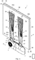
- a support structure 1 for supporting the user of a mobility device, or the like, is illustrated.
- the support structure 1 has two fluid flow channels 20.
- the fluid flow channels 20 have a fluid inlet 22 and a fluid outlet 50.
- the fluid flow channels 20 have a length axis 20x, a width axis 20y and a depth axis 20z.
- substantially the whole of the fluid flow channels 20 are tapered.
- the tapered channels 20 have a first end 28 and a second end 30. The first end 28 is located proximal to the fluid inlet 22 and the second end 30 is located distal to the fluid inlet 22.
- the width 32 of the second end 30 of the tapered channels 20 is greater than the width 33 of the first end 28 of the tapered channels 20.
- the maximum width of each tapered channel 20 is located furthest from the fluid inlet 22. The maximum width is therefore located at the second end 30 of each tapered channel 20.
- the maximum width of each tapered channel 20 could be located at other locations throughout the fluid flow channel 20.
- at least a part of (rather than substantially all of) each fluid flow channel 20 could be tapered.
- each fluid flow channel 20 comprises a top section 21, a bottom section 20b and sidewalls 20c.
- Each fluid flow channel 20 has a length, width and depth.
- the length of each fluid flow channel 20 is the distance between the first end 28 and the second end 30.
- the width of each fluid flow channel 20 is the distance between the sidewalls 20c.
- the depth of each fluid flow channel 20 is the distance between the top section 21 and the bottom section 20b. In the embodiment illustrated and described here, the minimum width of each tapered channel 20 is located closest to the fluid inlet 22.
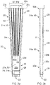
- the tapered channel 20 is formed by the divergence of the sidewalls 20c of each fluid flow channel 20. That is, the minimum distance between the sidewalls 20c is located proximal to the fluid inlet 22, and the maximum distance between the sidewalls 20c is located distal to the fluid inlet 22. In this arrangement, the divergence of the sidewalls 20c occurs from proximal the fluid inlet 22 to distal the fluid inlet 22. As shown in Fig. 3 , the depth of the first end 28 of the at least part tapered fluid flow channel 20 is greater than the depth of the second end 30 of the at least part tapered fluid flow channel 20.
- the sidewalls 20c of each fluid flow channel 20 are substantially elongate planar members. Without wishing to be bound by theory, it is thought that substantially planar sidewalls 20c prevent the formation of eddies, and thus substantially planar sidewalls 20c increase the efficiency of fluid-flow within each fluid flow channel 20.
- the fluid outlet 50 is formed from an open part 21a of the top section 21 of the fluid flow channel 20.
- the top section 21 of the fluid flow channel 20 also comprises a closed part 21b.
- the fluid outlet 50 could be formed from one or more apertures in each fluid flow channel 20.
- Each fluid flow channel 20 is configured such that fluid can flow from the fluid inlet 22 to the fluid outlet 50.
- Each tapered channel 20 allows fluid from the fluid inlet 22 to flow throughout the fluid flow channel 20, such that fluid can exit from the fluid outlet 50 throughout the whole of fluid flow channel 20. This exiting of fluid throughout the whole of the fluid flow channel 20 is used to provide fluid to the user of a mobility device over a wider area.
- substantially the whole of the top section 21 of each fluid flow channel 20 is open 21a.
- the open section 21a of the top section 21 forms the fluid outlet 50.
- the top section 21 of each fluid flow channel 20 could be formed mainly by a closed section 21b, but the closed section 21b having a number of apertures that act as fluid outlets 50.
- the fluid outlet 50 comprises a first end 50a and a second end 50b.
- the first end 50a of the fluid outlet 50 is located proximal to the fluid inlet 22 and has a width 51y
- the second end 50b of the fluid outlet 50 is located distal to the fluid inlet 22 and has a width 50y.
- the width 50y of the second end 50b of the fluid outlet 50 is greater than the width 51y of the first end 50a of the fluid outlet 50.
- the fluid outlet 50 is tapered.
- the fluid outlet 50 is substantially the same shape as the tapered channels 20.
- the fluid is air.
- the fluid flow channel 20 has a number of fins 60, which are elongate longitudinal members arranged substantially longitudinally from the first end 28 of each fluid flow channel 20 to the second end 30 of each fluid flow channel 20.
- Each fin 60 comprises a first end 60a and a second end 60b, the first end 60a of each fin 60 being located proximal to the fluid inlet 22 and the second end 60b of each fin 60 being located distal to the fluid inlet 22.
- the separation between the fins 60 is greater at the second end 60b than at first end 60a.
- the fins 60 are tapered. This arrangement of the fins 60 minimises the obstruction of the flow of fluid from the fluid inlet 22.
- each fin 60 measured with reference to the depth axis 20z, has an arcuate shape from proximal to the fluid inlet 22, to distal to the fluid inlet 22. That is, the profile of each fin, measured from proximal to the fluid inlet 22, to distal to the fluid inlet 22, has an arcuate shape.
- the fins 60 prevent each fluid flow channel 20 from becoming partially or completely blocked by the weight of the user.
- the fins 60 provide support to the user and are made from a resilient material, such as, for example, polyurethane or a moulded elastomer.
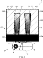
- the support structure 1 comprises first, second and third support layers 70, 80, 90, which are substantially planar members.
- the support layers 70, 80, 90 are made from a foam like material.
- the support layers 70, 80, 90 could be made from a memory foam type material, to provide support and comfort to the user.
- the first and second support layers 70, 80 have shaped sections, which act as fluid flow channel engagement sections 72, 82.
- the first and second support layers 70, 80 substantially surround the fluid flow channels 20.
- the fluid flow channel engagement sections 72, 82 are tapered to substantially match the shape of the fluid flow channels 20, and also the shape of the fluid outlet 50.
- the third support layer 90 inter alia protects, and provides support to, the fluid flow channels 20.
- the support structure 1 will typically be attached to a mobility device, and the third support layer 90 minimises the wear and tear that would result from the fluid flow channels 20 contacting the mobility device.
- the third support layer 90 minimises the wear and tear caused to other parts of the support structure 1 by preventing those parts of the support structure 1 from contacting the fluid flow channel 20.
- the third support layer 90 also contributes to the support and comfort provided to the user.
- the first support layer 70 may be folded over the third support layer 90. In this arrangement, at least a section of the first support layer 70 also provides protection, and provides support to, the fluid flow channels 20.
- the support structure 1 comprises a first fluid dispersion layer 100.
- the first fluid dispersion layer 100 is formed from two parts 100a, 100b that are attached together to form a pouch, which can then be placed over the support layers 70, 80, 90.
- the first fluid dispersion layer 100 is then secured in place by way of a fastening mechanism 110 in order to surround the first, second and third support layers 70, 80, 90.
- the fastening mechanism 110 is a plurality of snap fasteners, however other fastening mechanisms 110 could be used.
- the fastening mechanism 110 could be one or more, or a plurality of, stitches.
- the first fluid dispersion layer 100 is made from a fabric material.
- a part of the first fluid dispersion layer 100 is porous 102, and the remaining part of the fluid dispersion layer is non-porous 104.
- the non-porous part 104 is configured to substantially block the flow of fluid therethrough.
- the first fluid dispersion layer 100 is configured to allow fluid exiting the fluid outlet 50 to flow through the porous part 102.
- the porous part 102 which in this embodiment has a larger surface area than the fluid outlet 50, disperses fluid from the fluid outlet 50.
- the dispersion of the fluid results in fluid being provided to the user over a wider area, and thus the cooling effect of providing fluid to the user is dispersed over a wider area. This is advantageous when cooling the user, and when removing moisture from the user.
- the user is less aware of the flow of fluid. That is, in the absence of a fluid dispersion layer 100, the user will be more aware of the flow of fluid from the fluid flow channel 20 to the user, as the fluid flow would be concentrated on only those sections where there is a fluid outlet 50.
- the provision of the first fluid dispersion layer 100 thus improves the comfort of the user.
- the non-porous part 104 of the first fluid dispersion layer 100 can be used to better direct the flow of fluid from the fluid outlet 50 through the first fluid dispersion layer 100. As depicted in Fig. 4 , the non-porous part 104 blocks a substantial portion of the fluid outlet 50, and is located on a lower region 111 of the first fluid dispersion layer 100. In this arrangement, the fluid flow can be controlled by changing the layout of the non-porous part 104 and the porous part 102. For example, if the support structure 1 is used as a back rest for a mobility device, the size of the non-porous part 104 could be selected in order to direct more fluid towards a user's back or towards a particular area of a user's back.
- non-porous part 104 could be selected to provide different fluid flow patterns as desired by the user, or as designed for.
- the fluid outlet 50 could be comprised of open and closed portions to provide for customised fluid flow, depending upon the needs of the user.
- a part of the fluid outlet 50 overlaps with the porous part 102 of the first fluid dispersion layer 100.
- substantially the whole of the fluid outlet 50 could be configured to overlap with the porous part 102 of the first fluid dispersion layer 100.
- the width of the porous part 102 of the first fluid dispersion layer 100 is greater than the width of the fluid outlet 50.
- the length of the porous part 102 of the first fluid dispersion layer 100 is greater than the length of the fluid outlet 50.
- the support structure 1 is foldable, by way of a flexible region 92. Folding the support structure 1 assists in the ability to transport the present invention, for example, when travelling by road, air, rail etc. A person may carry the support structure 1, for example, underarm in a more convenient manner because the support structure 1 is foldable.
- the third support layer 90 is divided into two parts 90a, 90b.
- the second support layer 80 is also divided into two parts 80a, 80b.
- the flexible region 92 is formed from the gap 92a and the gap 92b in combination with the first support layer 70, the gaps 92a and 92b enabling the support structure 1 to be folded along the path formed by the gaps 92a and 92b.
- the flexible region 92 could be a notch within, one or more of the support layers 70, 80, 90.
- the flexible region 92 allows the support structure 1 to be foldable, at least in part because the centre part of the support structure 1 does not contain any fluid flow components.
- the width of the gap 92a in the third support layer 90 is greater than the width of the gap 92b in the second support layer 80, which improves the ability of the support structure 1 to be folded.
- the first support layer 70 comprises a length of between approximately 300 mm and approximately 420 mm, a width of between approximately 300 mm and approximately 420 mm, and a thickness of between approximately 5 mm and approximately 15 mm.
- the second support layer 80 comprises a length of between approximately 300 mm and approximately 420 mm, a width of between approximately 300 mm and approximately 420 mm, and a thickness of between approximately 5 mm and approximately 15 mm.
- the third support layer 90 comprises a length of between approximately 300 mm and 420 mm, a width of between approximately 300 mm and 420 mm, and a thickness of between approximately 3 mm and approximately 7 mm.
- the third support layer 90 could have a length of between approximately 320 mm and 340 mm.
- the first support layer 70 could comprise a length of between approximately 300 mm and approximately 770 mm
- the second support layer 80 could comprise a length of between approximately 300 mm and approximately 770 mm
- the third support layer 90 could comprise a length of between approximately 300 mm and approximately 770 mm.
- the support structure 1 further comprises a second fluid dispersion layer 112.
- the second fluid dispersion layer 112 is configured to surround the support layers 70, 80, 90 and the fluid flow channel 20.
- the second fluid dispersion layer 112 can be attached to a mobility device by way of a fastening mechanism 114, which is formed by hook and loop fasteners located on flaps.
- the second fluid dispersion layer 112 thus attaches the support structure 1 to the mobility device.
- the second fluid dispersion layer 112 comprises a fluid flow control apparatus attachment mechanism 114', which may be used to attach a fluid flow control apparatus 3 to the second fluid dispersion layer 112.
- the support structure 1 need not comprise a second fluid dispersion layer 112.
- the second fluid dispersion layer 112 need not comprise a fastening mechanism 114.
- the second fluid dispersion layer 112 comprises a porous part 116 and a non-porous part 118.
- the porous part 116 is configured to allow fluid to flow from the first fluid dispersion layer 100, through the second fluid dispersion layer 112 to the user.
- the non-porous part 118 is configured to block the flow of fluid.
- the porous part 116 is substantially rectangular in shape, with two arcuate, or sine wave shaped, sides. It should be understood that the porous part of the second fluid dispersion layer 112 could be of a number of different shapes, and could comprise different layouts of porous 116 and non-porous 118 sections.
- the porous part 102 of the first fluid dispersion layer 100 provides a wicking effect, in order to wick moisture away from the user.
- the porous part 116 of the second fluid dispersion layer 112 also provides a wicking effect, in order to wick moisture away from the user.
- the second fluid dispersion layer 112 provides fluid to the user. It should be appreciated that in some embodiments it may be the second fluid dispersion layer 112 that provides a wicking effect.
- the fluid dispersion layers 100, 112 may be detached, cleaned, and re-attached to improve the ease of maintaining and cleaning the support structure 1.
- the support structure is attached to a fluid flow control apparatus 3, which in this embodiment is a fan 4.
- the support structure could comprise a fluid flow control apparatus 3.
- the fluid flow control apparatus 3 could be a pump, or the like.
- the fan 4 is a rotary fan, and is housed within a housing 7.
- the housing 7 has a fan inlet 5, through which ambient air can flow into the fan 4, and a fan outlet 6 through which air from the fan 4 can flow.
- the fan outlet 6 of the housing 7 is engageable with the fluid inlet 22 of the support structure 1 by way of an attachment mechanism 8, which is a snap fit connector.
- the fluid flow control apparatus 3 is detachable which improves the ability of the support structure 1 to be transported.
- the user may disconnect the fluid flow control apparatus 3 from the support structure 1, and fold the support structure 1, to assist in the transport of the support structure 1. It should be understood that the fluid flow control apparatus 3 could be attached to the second fluid dispersion layer 112 by way of the fluid flow control apparatus attachment mechanism 114'.
- a rechargeable battery for example, a lithium ion battery.
- the battery is housed within the housing 7.
- the battery is configured to provide a voltage of between approximately 2.4 Volts and 4.2 Volts.
- the battery is configured to provide a maximum current of 3 Amperes.
- the battery is configured such that, in use, the battery provides electrical power to the fluid flow control apparatus for between approximately 3 hours and 20 hours.
- the battery has a capacity of between approximately 7000 mAh and 9000 mAh.
- a control module 120 is configured to control the fluid flow control apparatus 3.
- the control module 120 may control the flow rate of fluid flowing to the user.
- the control module 120 is therefore operable to control the temperature of the user by controlling the operation of the fluid flow control apparatus 3.
- the control module 120 is housed within a remote control, which is connected to the fluid flow control apparatus 3.
- the control module 120 could control the fluid flow control apparatus 3 by way of wireless communication.
- the support structure 1 illustrated and described here is able to cool a user of a mobility device by way of convection cooling.
- the support structure 1 also contributes to increased evaporation of moisture from the user by providing fluid to the user, and/or through the wicking mechanism of the fluid dispersion layers 100, 112.
- Fig. 9 depicts an alternative embodiment of the second fluid dispersion layer 112 of Fig. 8 .
- the second fluid dispersion layer 112 is the same as that shown in Fig. 8 , with the exception that the layout of the non-porous section 118 and the porous section 116 is different.
- the non-porous section 118 is only located on a lower region of the second fluid dispersion layer 112.
- the non-porous section 118 of the second fluid dispersion layer 112 has a rectangular cross section.
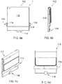
- Fig. 10 shows an alternative embodiment of the first, second and third support layers 70, 80, 90.
- the second support layer has a top surface 83.
- the third support layer 90 has a top surface 93, a front surface 91a and a back surface 91b.
- the first support layer 70 has an upper section 70a.
- the first, second and third support layers 70, 80, 90 have a length axis 70x.
- the length of the first, second and third support layers 70, 80, 90 is in the direction of the length axis 70x.
- the length of the first support layer 70 is greater than the length of the second support layer 80.
- the length of the first support layer 70 is also greater than the length of the third support layer 90.
- the length of the second support layer 80 is greater than the length of the third support layer 90.
- the length of the second and third support layers 80, 90 could be substantially equal. Because the length of the first support layer 70 is greater than the length of the second and third support layers 80, 90, the upper region 70a of the first support layer 70 can be folded over the second and third support layers 80, 90 as will be described in more detail below.
- first, second and third support layers 70, 80, 90 are brought together, such that the first support layer 70 is adjacent to the second support layer 80, and such that the second support layer 80 is adjacent to the third support layer 90.
- the upper section 70a of the first support layer 70 is folded around the top surface 83 of the second support layer 80 and around the top surface 93 and back surface 91b of the third support layer 90.
- the upper section 70a of the first support layer 70 encapsulates the second support layer 80.
- a top edge 70b of the first support layer 70 abuts the back surface 91b of the third support layer 90.
- the second support layer 80 comprises a flexible section 81.
- the flexible section 81 allows a portion of the second support layer 80 to be folded. It should be understood that in some arrangements, the second support layer 80 need not have a flexible section 81. For example, if the second and third support layers 80, 90 are substantially equal in length, the upper region 70a of the first support structure 70 could be folded over the second and third support layers 80, 90, without the need for a flexible section 81 in the second support layer 80.
- the flexible section 81 is a corrugated section. However, it should be understood that other types of flexible section could be used.
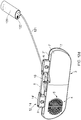
- Fig. 11 shows an alternative embodiment of the fluid flow channel 20 of the support structure 1.
- the fluid flow channel 20 shown in Fig 11 is substantially the same as those shown in Figs. 1 to 4 with the following differences.
- the fluid flow channel 20 comprises support layer engagement portions 20d in the form of protrusions 20e.
- the protrusions are tabs 20e.
- the fluid flow channel 20 comprises four protrusions 20e.
- the support layer engagement portion 20d could comprise other types of support layer engagement portion 20d.
- the support layer engagement portion 20d could comprise one or more protrusions, planar members and/or tabs 20e.
- the support structure 1 is arranged such that the support layer engagement portion 20d is engageable with the first support layer 70 and the second support layer 80.
- the support layer engagement portion 20d could engage with one or more of the first support layer 70, the second support layer 80 and the third support layer 90.
- Each support layer engagement portion 20d is located on an outer surface 20g of the sidewall 20c of the fluid flow channel 20 that is in contact with or that faces the first support layer 70 and the second support layer 80.
- the support layer engagement portion 20d comprises one or more protrusions 20e located on the outer surface 20g of the sidewalls 20c of the fluid flow channel 20.
- each of the protrusions 20e are planar members or tabs. Each of the protrusions 20e are angled away from the outer surface 20g of the sidewalls 20c of the fluid flow channel 20. Each of the protrusions 20e could be angled away from the outer surface 20g of the sidewalls 20c of the fluid flow channel 20 by up to approximately 90°. In this embodiment, the protrusions 20e slope generally towards the inlet 22 of the fluid flow channel 20.
- each of the protrusions 20e could be angled away from the outer surface 20g of the sidewalls 20c of the fluid flow channel 20 by up to 90°.
- the protrusions 20e slope generally towards the inlet 22 of the fluid flow channel 20.
- some of the protrusions 20e could slope generally towards the inlet 22 of the fluid flow channel 20, and some of the protrusions 20e could slope generally away from the inlet 22 of the fluid flow channel 20.
- the protrusions 20e could slope generally away from the inlet 22 of the fluid flow channel 20.
- the protrusions 20e When the protrusions 20e engage with the first support layer 70 and the second support layer 80, the protrusions 20e mitigate movement of the first support layer 70 and the second support layer 80.
- the support structure engagement portion 20d is used in this embodiment to reduce the risk of this problem occurring by mitigating movement of the support layers 70, 80 and 90 with respect to the fluid flow channel 20.
- the first support layer 70, the second support layer 80 and the third support layer 90 are configured to accommodate substantially all of the support layer engagement portion 20d by way of eight slits 74 and 84 in each of the first support layer 70 and the second support layer 80.
- the fluid flow channel 20 comprises a rigid member 20f connected to the sidewalls 20c of the fluid flow channel 20.
- the rigid member 20f is located substantially on the bottom section 20b of the fluid flow channel 20 and is integrally formed with the fluid flow channel 20.
- the rigid member 20f is a series of struts arranged in a hatch arrangement, which in this embodiment is a substantially rhombus hatch arrangement.
- the rigid member 20f could be one or more, rods, bars, or the like.
- the rigid member 20f is configured to mitigate deformation of the fluid flow channel 20.
- the rigid member 20f is configured to increase the rigidity of the fluid flow channel 20.
- the rigid member 20f is configured to provide support to the fluid flow channel 20.
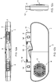
- Fig. 12 shows an alternative embodiment of the fluid flow control apparatus 3, which is substantially the same as the fluid flow control apparatus 3 shown in Figs. 1 and 4 , with the following differences.
- the fluid flow control apparatus 3 comprises an electrical connector 10 located on an upper region 7' of the fluid flow control apparatus 3.
- the electrical connector is located on a top surface 7" of the fluid flow control apparatus 3 substantially adjacent to the fan outlet 6 of the housing 7 of the fluid flow control apparatus 3.
- the fluid flow control apparatus 3 is connected to a control module 120 by way of a wired connection 121.
- the rechargeable battery of the fluid flow control apparatus 3 can be recharged by way of a universal serial bus (USB) port 122 of the control module 120.
- USB universal serial bus
- the fluid flow control apparatus 3 comprises a frame member 9.
- the frame member 9 is secured to the housing 7 of the fluid flow control apparatus 3 by way of a glue (an example of an adhesive).
- the frame member 9 is a planar member. However, it should be understood that the frame member 9 could be a bar, a rod, a pole, a cable, or the like. In some embodiments, the frame member 9 may be integrally formed with the housing 7 of the fluid flow control apparatus 3.
- the second fluid dispersion layer 112 is attachable to the frame member 9 by way of the fastening mechanism 114' of the second fluid dispersion layer 112.
- the fluid inlet 22 of the fluid flow channel 20 can be connected to the fan outlet 6 of the housing 7 of the fluid flow control apparatus 3 by way of an attachment mechanism 12.
- the attachment mechanism 12 is a releasable attachment mechanism 12 comprising a plug 13 and a socket 14.
- the plug 13 comprises socket engagement portions.
- two of the socket engagement portions are resilient, flexible members 13' biased to be in a first position.
- two of the socket engagement portions 13' comprise a substantially rounded rectangular cuboid.
- Each socket 14 comprises two plug engaging portions, which in this embodiment are apertures 14' in each socket 14.
- the plug 13 and the socket 14 are configured to be moveable between an unlocked state and a locked state.
- the two socket engagement portions 13' move from the first position to a second position, and then from the second position to the first position.
- the end user can unlock the fluid flow channels 20 from the housing 7 of the fluid flow control apparatus 3 by pressing on the socket engagement portions 13'.
- Fig. 13 shows an alternative embodiment of the first support layer 70 and the second support layer 80, which is substantially the same as the first support layer 70 and the second support layer 80 shown in Fig. 10 with the following differences.
- the alternative embodiment of the first support layer 70 and the second support layer 80 shown in Fig. 13 is capable of being used with the alternative embodiment of the fluid flow channel 20 shown in Fig. 11 , and it is also capable of being used with the fluid flow channel 20 depicted in Figs. 1 to 4 .
- the first support layer 70 and the second support layer 80 are configured to accommodate at least a part of the support layer engagement portions 20d of the fluid flow channel 20, by way of eight slits 74 and 84.
- the fluid flow channels 20 can be placed into the fluid flow channel engagement portions 72 and 82, and the protrusions 20e of each fluid flow channel 20 can be inserted into the slits 74 and 84 of the first support layer 70 and the second support layer 80.
- the slits could be slots, cut-out portions, or the like.
- at least one of the first support layer 70, the second support layer 80, and the third support layer 90 could be configured to accommodate at least a part of the support layer engagement portions 20d of the fluid flow channel 20.
- the first support layer 70 and the second support layer 80 each comprise eight slits 74 and 84, it should be understood that at least one of the first support layer 70, the second support layer 80 and the third support layer 90 could be configured to accommodate at least a part of the support layer engagement portion 20d of the fluid flow channel 20 by way of one or more slots, slits, cut-out portions, or the like.
- At least a part of the support structure 1 may be foldable to fit around a mobility device, or the like. At least a part of the support structure 1 may be foldable around a backrest of a mobility device, or the like. This allows the support structure 1 to be fitted to a range of different types and sizes of mobility devices. Furthermore, folding the support structure 1 in this way allows the support structure 1 to be secured to a mobility device 1 in a more reliable manner.
Description
- This invention relates to a support structure and particularly, but not exclusively, an apparatus for providing air to a support structure for supporting the body of a user, particularly a user of a mobility device or the like. The invention also relates to an apparatus for controlling the temperature of a support structure for supporting the body of a user, a method of providing fluid to the user of a mobility device, or the like, and a method of dispersing fluid.
- Users of mobility devices are known to experience discomfort due to the build-up of heat and moisture, which can also lead to pressure sores and skin atrophy in some cases. Known apparatuses and systems for mitigating or preventing the build-up of heat and moisture have a number of disadvantages. For example, some apparatuses and systems in the prior art increase the flow rate of air provided to the user by way of a fan and an air outlet arrangement, the air outlet directed to a specific area of the back, for example. However, such arrangements cool only a small area of the user and, because the air outlet is concentrated on one area, often result in that area of the user becoming too cold, while other areas of the user remain too warm. Additionally, the sensation of air being provided to a small area of the user can be unpleasant and/or irritating, particularly when, for example, the flow rate of the air has been increased by way of a fan and an air outlet arrangement. Furthermore, known apparatuses and systems often fail to remove moisture from the person. These disadvantages can contribute to further discomfort for the user.
- Therefore, there remains a need to address at least some of these problems. In particular, there is a desire to reduce the build-up of heat and moisture experienced by users of mobility devices.
- Therefore, it is an object of the invention to obviate or mitigate at least some of the disadvantages of the prior art.
- It is an object of the present invention to provide a support structure for reducing the build-up of heat and/or moisture experienced by a user of a mobility device. It is a further object of the invention to provide a method of reducing the build-up of heat and/or moisture experienced by a user of a mobility device.
- The term "mobility device" used herein should be understood to include all types of personal mobility device, such as wheelchairs, mobility scooters, and the like.
-
DE102013020799 discloses a pad (10) having a seat aerator (36) provided with an air circulation arrangement (34) that is provided with multiple channels (26) extending inside the pad. A generating element is arranged in the pad for generating air flow through the air circulation arrangement, where the generating element generates the air flow through two heating elements (18). One of the heating elements is integrated into a heating mat (16) and designed as a heating wire (20). The other heating element is designed as a PTC heating element and arranged in a suction passage of the air circulation arrangement. - According to the invention there is provided a support structure for supporting the user of a mobility device or the like, the support structure comprising:
a fluid flow channel, the fluid flow channel comprising: - a fluid inlet; and
- a top section comprising one or more apertures, the one or more apertures forming one or more fluid outlets in the top section; wherein at least part of the fluid flow channel is tapered, the at least part tapered fluid flow channel comprising a first end and a second end;
- It will be appreciated that the at least part tapered fluid flow channel has at least a tapered part.
- At least a part of the fluid flow channel may be flexible. The fluid flow channel may be flexible. The fluid flow channel may be a flexible member. The support structure may be a cushion. The support structure may be a back rest cushion. The support structure may be a mobility device cushion. The support structure may be a wheelchair cushion. The support structure may be a wheelchair back rest cushion. The support structure may be a seat cushion. The support structure may be a mobility device seat cushion. The support structure may be a wheelchair seat cushion.
- Substantially the whole of the fluid flow channel may be tapered. The maximum width of the at least part tapered fluid flow channel may be located at the second end of the at least part tapered fluid flow channel. The minimum width of the at least part tapered fluid flow channel may be located at the first end of the at least part tapered fluid flow channel.
- The fluid flow channel may comprise sidewalls. The minimum separation distance between the sidewalls may be located at the first end of the at least part tapered fluid flow channel. The maximum separation distance between the sidewalls may be located at the second end of the at least part tapered fluid flow channel. The minimum separation distance between the sidewalls may be located at the first end of the at least part tapered fluid flow channel and the maximum separation distance between the sidewalls may be located at the second end of the at least part tapered fluid flow channel.
- The depth of the first end of the at least part tapered fluid flow channel may be greater than the depth of the second end of the at least part tapered fluid flow channel.
- The first end of the at least part tapered fluid flow channel may comprise a substantially rectangular cross section. The second end of the at least part tapered fluid flow channel may comprise a substantially rectangular cross section. The at least part tapered fluid flow channel may have a substantially rectangular cross section from the first end to the second end. The area of the cross section of the first end of the at least part tapered fluid flow channel may be greater than the area of the cross section of the second end of the at least part tapered fluid flow channel.
- The top section of the fluid flow channel may comprise an open part, the open part of the top section of the fluid flow channel defining the fluid outlet. The top section may comprise a closed part and the closed part of the top section of the fluid flow channel may be located proximal to the fluid inlet. Substantially the whole of the top section of the fluid flow channel may be open, such that it forms the fluid outlet.
- The width of the second end of the fluid outlet may be greater than the width of the first end of the fluid outlet.
- The fluid outlet may be substantially the same shape as the top surface of the at least part tapered fluid flow channel. The fluid outlet may be substantially the same shape as the at least part tapered fluid flow channel.
- The fluid may be air.
- The fluid flow channel may comprise one or more fins. The, or each, fin may be an elongate longitudinal member. The, or each, fin may be arranged substantially longitudinally from the first end of the at least part tapered fluid flow channel to the second end of the at least part tapered fluid flow channel.
- The fins may be arranged in a tapered arrangement. Each fin may comprise a first end and a second end, the first end of each fin being located proximal to the fluid inlet and the second end of each fin being located distal to the fluid inlet, and the separation between the fins may be greater at the second end than at the first end.
- The profile of the, or each, fin from proximal to the fluid inlet, to distal to the fluid inlet, may have an arcuate shape. The, or each, fin may be made from a resilient material such that the fins are configurable to provide support to the user.
- The support structure may comprise a first support layer. The support structure may comprise a second support layer. The first support layer may be adjacent to the second support layer. At least one of the first support layer and the second support layer may comprise a fluid flow channel engagement section. At least one of the first support layer and the second support layer may comprise a fluid flow channel engagement section, the fluid flow channel engagement section being configured to engage with the at least part-tapered fluid flow channel. At least one of the first support layer and the second support layer may comprise a fluid flow channel engagement section, the fluid flow channel engagement section being configured to engage with the fluid flow channel.
- At least one of the first support layer and the second support layer may substantially surround the fluid flow channel. At least a part of the fluid flow channel engagement section may be tapered. At least a portion of the fluid flow channel engagement section, and at least a portion of the fluid flow channel, may be arranged to be substantially co-planar.
- At least a portion of the fluid flow channel engagement section, and at least a portion of the fluid outlet, may be arranged to be co-planar. The fluid flow channel engagement section may be substantially identical in shape to the fluid flow channel. The fluid flow channel engagement section may be substantially identical in shape to the fluid outlet.
- The first support layer may be a substantially planar member. The first support layer may be a substantially rectangular planar member. The second support layer may be a substantially planar member. The second support layer may be a substantially rectangular planar member. At least one of the first support layer and the second support layer may be a substantially planar member.
- The first support layer may be made from a resilient material. The second support layer may be made from a resilient material. At least one of the first support layer and the second support layer may be made from a resilient material.
- The support structure may comprise a third support layer. The third support layer may be a substantially planar member. The third support layer may be a substantially rectangular planar member. The second support layer may be located between the first support layer and the third support layer.
- The support structure may be configurable to be foldable by way of a flexible region. The third support layer may comprise at least two parts, the at least two parts being spaced apart to provide a gap therebetween. The second support layer may comprise at least two parts, the at least two parts being spaced apart to provide a gap therebetween. The gap between the at least two parts of the second support layer, and/or the gap between the at least two parts of the third support layer, may provide a flexible region.
- The width of the gap between the at least two parts of the third support layer may be greater than the width of the gap between the at least two parts of the second support layer. The length of the first support layer may be greater than the length of the second support layer. The length of the first support layer may be greater than the length of the third support layer. The length of the second support layer may be greater than the length of the third support layer. The second support layer may be configured to be foldable by way of a flexible section of the second support layer. The length of the first support layer may be greater than the length of the second support layer and the length of the first support layer may be greater than the length of the third support layer, the first support layer being configured to be foldable such that at least an edge of the first support layer abuts the third support layer.
- The first support layer may comprise a length of between approximately 300 mm and approximately 420 mm. The first support layer may comprise a width of between approximately 300 mm and approximately 420 mm. The first support layer may comprise a thickness of between approximately 5 mm and approximately 15 mm. The first support layer may comprise a length of between approximately 300 mm and approximately 770 mm.
- The second support layer may comprise a length of between approximately 300 mm and approximately 420 mm. The second support layer may comprise a width of between approximately 300 mm and approximately 420 mm. The second support layer may comprise a thickness of between approximately 5 mm and approximately 15 mm. The second support layer may comprise a length of between approximately 300 mm and approximately 770 mm.
- The third support layer may comprise a length of between approximately 300 mm and approximately 420 mm. The third support layer may comprise a width of between approximately 300 mm and approximately 420 mm. The third support layer may comprise a thickness of between approximately 3 mm and approximately 7 mm. The third support layer may comprise a length of between approximately 300 mm and approximately 770 mm.
- The support structure may comprise a first fluid dispersion layer. The support structure may be arranged such that fluid can flow from the fluid outlet through the first fluid dispersion layer. The first fluid dispersion layer may be made from a fabric material.
- At least part of the first fluid dispersion layer may be porous. At least part of the first fluid dispersion layer may be non-porous. The porous part of the first fluid dispersion layer may be configured to allow fluid to pass therethrough. The non-porous part of the first fluid dispersion layer may be configured to mitigate or prevent the flow of fluid.
- The porous part of the first fluid dispersion layer and the fluid outlet may at least partially overlap. The width of the porous part of the first fluid dispersion layer may be greater than the width of the fluid outlet.
- The length of the porous part of the first fluid dispersion layer may be greater than the length of the fluid outlet.
- The porous part of the first fluid dispersion layer may be a high surface area to volume ratio structure. The porous part of the first fluid dispersion layer may be a mesh structure, or the like.
- The non-porous part of the first fluid dispersion layer may be located on a lower region of the first fluid dispersion layer. The first fluid dispersion layer may be configured to substantially surround the support structure.
- The first fluid dispersion layer may be configured to substantially surround the fluid flow channel. The first fluid dispersion layer may be configured to substantially surround the first support layer. The first fluid dispersion layer may be configured to substantially surround the second support layer. The first fluid dispersion layer may be configured to substantially surround the third support layer. The first fluid dispersion layer may be configured to substantially surround the fluid flow channel and at least one of the first support layer, or the second support layer, or the third support layer. The first fluid dispersion layer may be a pouch, or the like. The support structure may comprise a second fluid dispersion layer. The second fluid dispersion layer may be configured to allow fluid from the first fluid dispersion layer to flow to the user.
- At least part of the second fluid dispersion layer may be porous, and/or at least part of the second fluid dispersion layer may be non-porous. The porous part of the second fluid dispersion layer may be configured to allow the flow of fluid therethrough. The non-porous part of the second fluid dispersion layer may be configured to mitigate or prevent the flow of fluid.
- The porous part of the second fluid dispersion layer and the porous part of the first fluid dispersion layer may at least partially overlap. The width of the porous part of the second fluid dispersion layer may be greater than the width of the fluid outlet. The length of the porous part of the second fluid dispersion layer may be greater than the length of the fluid outlet. The porous part of the second fluid dispersion layer may be a high surface area to volume ratio structure.
- The porous part of the second fluid dispersion layer may be a mesh structure, or the like. The non-porous part of the second fluid dispersion layer may be located on a lower region of the second fluid dispersion layer. The non-porous part of the second fluid dispersion layer may be configured to substantially surround the porous part of the second fluid dispersion layer. The second fluid dispersion layer may be a pouch, or the like.
- The support structure may comprise, or is configured to attach to, a fluid flow control apparatus. The fluid inlet may be connectable to the fluid flow control apparatus.
- The fluid flow control apparatus may be a fan, or the like. The fluid flow control apparatus may be a pump, or the like.
- The fluid flow control apparatus may be formed within a housing. The housing may comprise a fan inlet and a fan outlet. The fan outlet may be connected to the fluid inlet of the fluid flow channel.
- The housing may comprise a pump inlet and a pump outlet. The pump outlet may be connected to the fluid inlet of the fluid flow channel. The pump inlet may be connected to a source of fluid.
- The support structure may comprise a control module. The control module may be configured to control the fluid flow control apparatus.
- The fluid flow control apparatus may comprise a battery. The battery may be a rechargeable battery. The battery may be a lithium ion battery.
- The battery may be operable to provide a voltage of between approximately 2.5 Volts and approximately 4.2 Volts. The battery may be operable to provide a maximum current of approximately 3 Amperes. The battery may be operable to provide a voltage of between approximately 2.5 Volts and approximately 4.2 Volts and/or a maximum current of approximately 3 Amperes. The battery may have a capacity of between approximately 7000 mAh and approximately 9000 mAh. The battery may have a capacity of approximately 7800 mAh. The battery may provide electrical power to the control module and the fluid flow control apparatus. In use, the battery may last for between approximately 3 hours and approximately 20 hours. In use, the battery may last for between approximately 3 hours and approximately 24 hours.
- The fluid inlet may be connectable to the fluid flow control apparatus by way of an attachment mechanism. The attachment mechanism may be a snap fit connector, a friction fit connector, a clamp connector, or the like. There may be one or more, or a plurality of, fluid inlets. The, or each, fluid inlet may be connectable to the fluid flow control apparatus. The fluid inlet may have a substantially rectangular cross section.
- The fluid outlet may comprise one or more, or a plurality of, apertures.
- The support structure may comprise one or more, or a plurality of, fluid flow channels. The support structure may comprise two fluid flow channels. The fluid flow channels may be spaced substantially equidistantly.
- The top section of the fluid flow channel may comprise one or more, or a plurality of, apertures. The sidewalls, of the fluid flow channel may comprise one or more, or a plurality of, apertures. The bottom section may comprise one or more, or a plurality of, apertures. The fluid outlet may be formed by one or more, or a plurality of, apertures in the top section, the sidewall or sidewalls, and/or in the bottom section. The top section of the fluid flow channel may comprise a porous membrane. The porous membrane may be a mesh structure.
- The, or each, fin may be made from a resilient material. The, or each, fin may be made from a plastics material. The, or each, fin may be made from polyurethane. The, or each, fin may be made from an elastomer material. The, or each, fin may be made from a moulded elastomer. The, or each, fin may be made from a resilient material such that, in use, the weight of the user does not deform the fluid flow channel. The, or each, fin may be made from a resilient material such that, in use, the weight of the user does not obstruct the flow of fluid within the fluid flow channel.
- The, or each, fin may comprise a first end and a second end. The first end of each fin may be located proximal to the fluid inlet. The second end of each fin may be located distal to the fluid inlet. The separation between the fins may be greater at the second end than at the first end. In this arrangement, the fins are tapered. In this arrangement, obstruction of the flow of fluid from the fluid inlet to the fluid outlet is minimised.
- At least a part of the sidewalls of the fluid flow channel may be substantially planar. The sidewalls of the fluid flow channel may be substantially planar members. The sidewalls of the fluid flow channel may be elongate members. The sidewalls of the fluid flow channel may be elongate planar members. Without wishing to be bound by theory, it is thought that substantially planar sidewalls prevent the formation of eddies, and thus substantially planar sidewalls increase the efficiency of fluid-flow within the fluid flow channel.
- The fluid flow control apparatus may comprise one or more fans. The, or each, fan may be a radial fan. The fluid flow control apparatus may comprise one or more pumps.
- The fluid outlet of the fluid flow control apparatus may be connectable to the fluid inlet of the fluid flow channel by way of an attachment mechanism. The attachment mechanism may be a snap fit connector. The attachment mechanism may be a releasable attachment mechanism. The attachment mechanism may comprise a plug and a socket.
- The plug may comprise one or more socket engagement portions. At least one of the socket engagement portions may be a resilient member. At least one of the socket engagement portions may be a flexible member. At least one of the socket engagement portions may be biased to be in a first position. At least one of the socket engagement portions may comprise a rectangular cuboid, which optionally is a substantially rounded rectangular cuboid.
- The socket may comprise one or more plug engaging portions. At least one of the plug engaging portions may be a slot, aperture, hole, or the like. At least one of the plug engaging portions may be a substantially rectangular shaped hole in the socket. At least one of the plug engaging portions may be a rectangular shaped hole in the socket, which optionally is a substantially rounded rectangular shaped hole.
- The plug and the socket may be configured to be moveable between an unlocked state and a locked state. When moved between the unlocked state and the locked state, at least one of the socket engagement portions may move from the first position to a second position, and optionally from the second position to the first position.
- The fluid flow control apparatus may comprise one or more batteries. The one or more batteries may be housed within the housing of the fluid flow control apparatus.
- The control module may be connectable to the fluid flow control apparatus. The control module may be configurable to control the fluid flow control apparatus. The control module may be configurable to control the flow rate of fluid exiting the fluid outlet of the fluid flow control apparatus. The control module may be configurable to control the fluid flow control apparatus by way of wireless communication. The control module may be configurable to control the fluid flow control apparatus by way of a wired connection between the control module and the fluid flow control apparatus. The fluid flow control apparatus may comprise an electrical connector. The electrical connector may be located on an upper region of the fluid flow control apparatus. The electrical connector may be located on a top surface of the fluid flow control apparatus. The electrical connector may be located substantially adjacent to the fan outlet of the housing of the fluid flow control apparatus. The control module may comprise one or more batteries. The control module may comprise one or more rechargeable batteries. The control module may comprise one or more universal serial bus (USB) ports. The one or more rechargeable batteries of the control module may be recharged by way of the USB port of the control module. The rechargeable battery of the fluid flow control apparatus may be recharged by way of the one or more USB ports of the control module. The rechargeable battery of the fluid flow control apparatus may be recharged by way of a charging port. The charging port may be located on the housing of the fluid flow control apparatus. The charging port may be located substantially adjacent to the rechargeable battery. The charging port may be located on a top surface of the fluid flow control apparatus. The charging port may be located substantially adjacent to the fan outlet of the housing of the fluid flow control apparatus.
- The first fluid dispersion layer may comprise one or more fluid dispersion layers. The first fluid dispersion layer may comprise a first part and a second part. The first fluid dispersion layer may comprise a first part and a second part, wherein the first part and the second part are attachable to each other. The first part and the second part may be attachable to each other, and may be configurable to fit over the support structure. In this arrangement, the first fluid dispersion layer may be placed over the support structure. In this arrangement, the first fluid dispersion layer may be placed over the support structure, and may be secured by way of a fastening mechanism, or attachment mechanism. The fastening mechanism may be one or more, or a plurality of, snap fasteners. The fastening mechanism may be one or more, or a plurality of, stitches, or the like.
- The first fluid dispersion layer may be configured to wick moisture away from the user. That is, the first fluid dispersion layer may be configured to remove fluid from the user by way of a wicking mechanism.
- The first fluid dispersion layer may comprise one or more, or a plurality of, non-porous sections. The, or each, non-porous section may be configurable to block the flow of fluid through the first fluid dispersion layer.
- The first fluid dispersion layer may comprise an upper region and a lower region. The lower region of the first fluid dispersion layer may be located proximal to the fluid inlet. The upper region of the first fluid dispersion layer may be located distal to the fluid inlet.
- The, or each, non-porous section may be located on the lower region of the first fluid dispersion layer. The, or each, non-porous section may be located on the upper region of the first fluid dispersion layer.
- The first fluid dispersion layer may comprise one or more fluid inlet engagement portions. The one or more fluid inlet engagement portions may be configurable to engage with, or substantially surround, the fluid inlet. In this arrangement, a portion of the first fluid dispersion layer surrounds the fluid inlet. The one or more fluid inlet engagement portions may be configurable to engage with, or substantially surround, a portion of the fluid flow control apparatus.
- The second fluid dispersion layer may be in the form of a cover layer. The second fluid dispersion layer may be in the form of a cover layer which acts as a housing for, for example, the first, second, and third support layers, the fluid flow channel, and the first fluid dispersion layer.
- The second fluid dispersion layer may be attachable to a mobility device, such as a wheelchair, or the like. The second fluid dispersion layer may be attachable to a mobility device, or the like, by way of a fastening mechanism. The fastening mechanism may be a hook and loop mechanism. In this arrangement, the second fluid dispersion layer may surround or house the support structure, and the second fluid dispersion layer may be attachable to a mobility device, or the like, such that the support structure is affixed to the mobility device.
- The second fluid dispersion layer may be configured to wick moisture away from the user. That is, the second fluid dispersion layer may be configured to remove fluid from the user by way of a wicking mechanism.
- At least a part of the second fluid dispersion layer may be porous. The porous part may be made from a porous, or mesh like, material. The porous part may have a substantially rectangular cross section. At least one edge of the porous part may be arcuate. At least one edge of the porous part may be sine wave shaped.
- The second fluid dispersion layer may comprise one or more, or a plurality of, non-porous sections. The, or each, non-porous section may be configurable to block the flow of fluid. In this arrangement, fluid may flow through the porous part of the second fluid dispersion layer. In this arrangement, fluid may be prevented from flowing through the non-porous section of the second fluid dispersion layer.
- The second fluid dispersion layer may comprise an upper region and a lower region. The lower region of the second fluid dispersion layer may be located proximal to the fluid inlet. The upper region of the second fluid dispersion layer may be located distal to the fluid inlet.
- The, or each, non-porous section may be located on the lower region of the second fluid dispersion layer. The, or each, non-porous section may be located on the upper region of the second fluid dispersion layer. The, or each, non-porous section may have a substantially rectangular cross section.
- The mobility device may be a wheelchair, or the like.
- One or more of the sidewalls of the fluid flow channel may comprise an outer surface that is in contact with or that faces at least one of the first support layer, the second support layer and the third support layer.
- The fluid flow channel may comprise a support layer engagement portion. The support structure may be arranged such that the support layer engagement portion is engageable with at least one of the first support layer, the second support layer and the third support layer. The support layer engagement portion may comprise one or more protrusions.
- At least a part of the support layer engagement portion may be located on one or more of the sidewalls of the fluid flow channel. At least a part of the support layer engagement portion may be located on one or more of the outer surfaces of the sidewalls of the fluid flow channel. The support layer engagement portion may comprise one or more protrusions located on one or more of the sidewalls of the fluid flow channel. The one or more protrusions may be located on one or more of the outer surfaces of the sidewalls of the fluid flow channel. The one or more protrusions may be planar members and/or tabs.
- The one or more protrusions may be angled away from the outer surface of the sidewalls. The one or more protrusions may be angled away from the outer surface of the sidewalls by up to approximately 90°. The one or more protrusions may be angled away from the outer surface of the sidewalls by up to approximately 90°, such that the protrusions slope generally towards the inlet of the fluid flow channel.
- At least one of the first support layer, the second support layer and the third support layer may be configured to accommodate at least a part of the support layer engagement portion. At least one of the first support layer, the second support layer and the third support layer may be configured to accommodate at least a part of the support layer engagement portion by way of one or more slots, slits, cut-out portions, or the like.
- The fluid flow channel may comprise a rigid member. The rigid member may be at least partly located on the bottom section of the fluid flow channel. The rigid member may be connected to the sidewalls of the fluid flow channel. The rigid member may be integrally formed with the fluid flow channel. The rigid member may be one or more struts, rods, bars, or the like. The rigid member may be arranged in a hatch arrangement. The hatch arrangement may be a substantially rhombus hatch arrangement, or the like. The rigid member may be configured to mitigate deformation of the fluid flow channel. The rigid member may be configured to increase the rigidity of the fluid flow channel. The rigid member may be configured to provide support to the fluid flow channel.
- The fluid flow control apparatus may comprise a frame member. The frame member may be releasably attachable to the housing of the fluid flow control apparatus. The frame member may be secured to the housing of the fluid flow control apparatus, optionally by way of an adhesive. The adhesive may be a glue, or the like. The frame member may be a bar, a rod, a pole, a cable, or the like. The frame member may be a planar member. The second fluid dispersion layer may be attachable to the frame member. The second fluid dispersion layer may be attachable to the frame member by way of the fastening mechanism of the second fluid dispersion layer. The frame member may be integrally formed with the housing of the fluid flow control apparatus. The frame member may be made from a plastic material.
- According to an embodiment there is provided an apparatus for providing fluid to a support structure for supporting the body of a user, the apparatus comprising:
a support structure for supporting the user, the support structure comprising:
a fluid flow channel, the fluid flow channel comprising: - a fluid inlet; and
- a top section comprising one or more apertures, the one or more apertures forming one or more fluid outlets in the top section; wherein at least part of the fluid flow channel is tapered, the at least part tapered fluid flow channel comprising a first end and a second end;
- The fluid may be air.
- The apparatus may further comprise a fluid flow control apparatus.
- The fluid flow control apparatus may be a fan. The fluid flow control apparatus may be a pump, or the like.
- Embodiments of the second aspect of the invention may include one or more features of the first aspect of the invention or its embodiments. Similarly, embodiments of the first aspect of the invention may include one or more features of the second aspect of the invention or its embodiments.
- According to a further embodiment of the invention there is provided a method of dispersing fluid, the method comprising the steps of:
providing a support structure for supporting a user, the support structure comprising:
a fluid flow channel, the fluid flow channel comprising: - a fluid inlet; and
- a top section comprising one or more apertures, the
- the first end of the tapered part being located proximal to the fluid inlet and the second end of the tapered part being located distal to the fluid inlet; wherein the width of the second end of the tapered part is greater than the width of the first end of the tapered part; and
- wherein the, or each, fluid outlet comprises a first end located proximal to the fluid inlet and a second end located distal to the fluid inlet; the method further comprising the steps of: providing fluid to the fluid flow channel via the fluid inlet, such that fluid flows through the fluid outlet to the user; and
- dispersing the fluid after or on flowing through the fluid outlet such that dispersed fluid is provided to the user.
- The fluid may be air.
- The method may comprise the further step of providing a fluid flow control apparatus.
- The method may comprise the step of connecting the fluid inlet to a fluid flow control apparatus.
- The fluid flow control apparatus may be a fan. The fluid flow control apparatus may be a pump, or the like.
- Embodiments of the third aspect of the invention may include one or more features of the first or second aspects of the invention or their embodiments. Similarly, embodiments of the first or second aspects of the invention may include one or more features of the third aspect of the invention or its embodiments.
- According to an another embodiment of the invention there is provided an apparatus comprising the support structure of the first aspect of the invention.
- Embodiments of the invention will now be described, by way of example, with reference to the drawings, in which:
-
Fig. 1 is an isometric view of the support structure according to an embodiment of this invention; -
Fig. 2a is a top view of one of the fluid flow channels of the support structure ofFig. 1 ; -
Fig. 2b is a side view of one of the fluid flow channels of the support structure ofFig. 1 ; -
Fig. 3 is an isometric view of one of the fluid flow channels of the support structure ofFig. 1 ; -
Fig. 4 is a front view of the support structure ofFig. 1 ; -
Fig. 5a is an isometric view of the first, second and third support layers of the support structure ofFig. 1 ; -
Fig. 5b is an exploded view of the first, second and third support layers of the support structure ofFig. 1 ; -
Fig. 6a is a front view of the first fluid dispersion layer of the support structure ofFig. 1 ; -
Fig. 6b is a back view of the first fluid dispersion layer of the support structure ofFig. 1 ; -
Fig. 7 is a top view of the support structure ofFig. 1 ; -
Fig. 8a is a front view of the second fluid dispersion layer of the support structure ofFig. 1 ; -
Fig. 8b is a side view of the second fluid dispersion layer of the support structure ofFig. 1 ; -
Fig. 8c is an isometric view of the second fluid dispersion layer of the support structure ofFig. 1 ; -
Fig. 8d is a back view of the second fluid dispersion layer of the support structure ofFig. 1 ; -
Fig. 9a is a front view of an alternative embodiment of the second fluid dispersion layer of the support structure ofFig. 1 ; -
Fig. 9b is a side view of an alternative embodiment of the second fluid dispersion layer of the support structure ofFig. 1 ; -
Fig. 9c is an isometric view of an alternative embodiment of the second fluid dispersion layer of the support structure ofFig. 1 ; -
Fig. 9d is a back view of an alternative embodiment of the second fluid dispersion layer of the support structure ofFig. 1 ; -
Fig. 10a is a front view of an alternative embodiment of the first, second and third support layers of the support structure ofFig. 1 ; -
Fig. 10b is a side view of an alternative embodiment of the first, second and third support layers of the support structure ofFig. 1 ; -
Fig. 10c is a top view of an alternative embodiment of the first, second and third support layers of the support structure ofFig. 1 ; -
Fig. 10d is an isometric view of a back section of an alternative embodiment of the first, second and third support layers of the support structure ofFig. 1 ; -
Fig. 10e is an isometric view of an alternative embodiment of the first, second and third support layers of the support structure ofFig. 1 ; -
Fig. 10f is an isometric view of an assembled alternative embodiment of the first, second and third support layers of the support structure ofFig. 1 ; -
Fig. 11a is an isometric view of an unassembled alternative embodiment of the fluid flow channel of the support structure ofFig. 1 ; -
Fig. 11b is an isometric view of an assembled alternative embodiment of the fluid flow channel of the support structure ofFig. 1 ; -
Fig. 11c is a top view of an assembled alternative embodiment of the fluid flow channel of the support structure ofFig. 1 ; -
Fig. 11d is an isometric view of an assembled alternative embodiment of the fluid flow channel of the support structure ofFig. 1 ; -
Fig. 11e is a front view of an assembled alternative embodiment of the fluid flow channel of the support structure ofFig. 1 ; -
Fig. 11f is a side view of an assembled alternative embodiment of the fluid flow channel of the support structure ofFig. 1 ; -
Fig. 11g is a back view of an assembled alternative embodiment of the fluid flow channel of the support structure ofFig. 1 ; -
Fig. 12a is a top view of an alternative embodiment of the fluid flow control apparatus of the support structure ofFig. 1 ; -
Fig. 12b is a front view of an alternative embodiment of the fluid flow control apparatus of the support structure ofFig. 1 ; -
Fig. 12c is a side view of an alternative embodiment of the fluid flow control apparatus of the support structure ofFig. 1 ; -
Fig. 12d is an isometric view of an alternative embodiment of the fluid flow control apparatus of the support structure ofFig. 1 ; -
Fig. 12e is an isometric view of an alternative embodiment of the fluid flow control apparatus of the support structure ofFig. 1 ; -
Fig. 13a is a front view of an alternative embodiment of the first support layer of the support structure ofFig. 1 ; and -
Fig. 13b is a front view of an alternative embodiment of the second support layer of the support structure ofFig. 1 . - With reference to
Figs. 1 to 5 , a support structure 1 for supporting the user of a mobility device, or the like, is illustrated. - With reference to
Fig. 1 the support structure 1 has twofluid flow channels 20. Thefluid flow channels 20 have afluid inlet 22 and afluid outlet 50. As best shown inFig. 3 , thefluid flow channels 20 have alength axis 20x, awidth axis 20y and adepth axis 20z. In the embodiment illustrated and described here, substantially the whole of thefluid flow channels 20 are tapered. The taperedchannels 20 have afirst end 28 and asecond end 30. Thefirst end 28 is located proximal to thefluid inlet 22 and thesecond end 30 is located distal to thefluid inlet 22. As best shown inFig. 3 , thewidth 32 of thesecond end 30 of the taperedchannels 20 is greater than the width 33 of thefirst end 28 of the taperedchannels 20. In this arrangement, the maximum width of each taperedchannel 20 is located furthest from thefluid inlet 22. The maximum width is therefore located at thesecond end 30 of each taperedchannel 20. However, it should also be understood that the maximum width of each taperedchannel 20 could be located at other locations throughout thefluid flow channel 20. It should also be understood that at least a part of (rather than substantially all of) eachfluid flow channel 20 could be tapered. Furthermore, it will be understood that there could be one or more, or a plurality of, taperedparts 20 within the, or each,fluid flow channel 20. In some embodiments, at least a part of thefluid flow channel 20 could be flexible. - As best shown in
Fig. 3 , eachfluid flow channel 20 comprises atop section 21, abottom section 20b andsidewalls 20c. Eachfluid flow channel 20 has a length, width and depth. The length of eachfluid flow channel 20 is the distance between thefirst end 28 and thesecond end 30. The width of eachfluid flow channel 20 is the distance between the sidewalls 20c. The depth of eachfluid flow channel 20 is the distance between thetop section 21 and thebottom section 20b. In the embodiment illustrated and described here, the minimum width of each taperedchannel 20 is located closest to thefluid inlet 22. - As shown in
Fig. 3 , the taperedchannel 20 is formed by the divergence of the sidewalls 20c of eachfluid flow channel 20. That is, the minimum distance between the sidewalls 20c is located proximal to thefluid inlet 22, and the maximum distance between the sidewalls 20c is located distal to thefluid inlet 22. In this arrangement, the divergence of the sidewalls 20c occurs from proximal thefluid inlet 22 to distal thefluid inlet 22. As shown inFig. 3 , the depth of thefirst end 28 of the at least part taperedfluid flow channel 20 is greater than the depth of thesecond end 30 of the at least part taperedfluid flow channel 20. - The sidewalls 20c of each
fluid flow channel 20 are substantially elongate planar members. Without wishing to be bound by theory, it is thought that substantiallyplanar sidewalls 20c prevent the formation of eddies, and thus substantiallyplanar sidewalls 20c increase the efficiency of fluid-flow within eachfluid flow channel 20. - As shown in
Figs. 1 and2 , in the embodiment illustrated here, thefluid outlet 50 is formed from anopen part 21a of thetop section 21 of thefluid flow channel 20. Thetop section 21 of thefluid flow channel 20 also comprises aclosed part 21b. However, it should be understood that thefluid outlet 50 could be formed from one or more apertures in eachfluid flow channel 20. - Each
fluid flow channel 20 is configured such that fluid can flow from thefluid inlet 22 to thefluid outlet 50. Each taperedchannel 20 allows fluid from thefluid inlet 22 to flow throughout thefluid flow channel 20, such that fluid can exit from thefluid outlet 50 throughout the whole offluid flow channel 20. This exiting of fluid throughout the whole of thefluid flow channel 20 is used to provide fluid to the user of a mobility device over a wider area. - Without wishing to be bound by theory, it is thought that for a fixed supply of fluid to the
fluid inlet 22, the absence of a taperedchannel 20 will result in a reduced amount of fluid reaching theupper region 23a of eachfluid flow channel 20 and an increase in the amount of fluid exiting thelower region 23b. This will then result in fluid being provided to the user over a reduced area. Subsequently, the cooling effect to the user will be reduced. The supply of fluid to thefluid inlet 22 will then need to be increased to achieve the same area of fluid provided to the user. This could result in, for example, the need for a larger fluid flow control apparatus 3 and/or a larger electrical power system or battery. - In this embodiment, as shown in
Figs. 1 and2 , substantially the whole of thetop section 21 of eachfluid flow channel 20 is open 21a. However, it should be understood that at least a part of thetop section 21 of eachfluid flow channel 20 could be open. Theopen section 21a of thetop section 21 forms thefluid outlet 50. For example, thetop section 21 of eachfluid flow channel 20 could be formed mainly by aclosed section 21b, but theclosed section 21b having a number of apertures that act asfluid outlets 50. - In this embodiment, and as best shown in
Fig. 2a , thefluid outlet 50 comprises afirst end 50a and asecond end 50b. Thefirst end 50a of thefluid outlet 50 is located proximal to thefluid inlet 22 and has a width 51y, and thesecond end 50b of thefluid outlet 50 is located distal to thefluid inlet 22 and has a width 50y. The width 50y of thesecond end 50b of thefluid outlet 50 is greater than the width 51y of thefirst end 50a of thefluid outlet 50. In this arrangement, thefluid outlet 50 is tapered. Thefluid outlet 50 is substantially the same shape as thetapered channels 20. - In this embodiment, the fluid is air.
- As best shown in
Fig. 3 , thefluid flow channel 20 has a number offins 60, which are elongate longitudinal members arranged substantially longitudinally from thefirst end 28 of eachfluid flow channel 20 to thesecond end 30 of eachfluid flow channel 20. Eachfin 60 comprises afirst end 60a and asecond end 60b, thefirst end 60a of eachfin 60 being located proximal to thefluid inlet 22 and thesecond end 60b of eachfin 60 being located distal to thefluid inlet 22. The separation between thefins 60 is greater at thesecond end 60b than atfirst end 60a. In this arrangement, thefins 60 are tapered. This arrangement of thefins 60 minimises the obstruction of the flow of fluid from thefluid inlet 22. - In the embodiment illustrated and described here, the height of each
fin 60, measured with reference to thedepth axis 20z, has an arcuate shape from proximal to thefluid inlet 22, to distal to thefluid inlet 22. That is, the profile of each fin, measured from proximal to thefluid inlet 22, to distal to thefluid inlet 22, has an arcuate shape. Thefins 60 prevent eachfluid flow channel 20 from becoming partially or completely blocked by the weight of the user. Thefins 60 provide support to the user and are made from a resilient material, such as, for example, polyurethane or a moulded elastomer. - As best shown in
Figs. 4 and5 , the support structure 1 comprises first, second and third support layers 70, 80, 90, which are substantially planar members. The support layers 70, 80, 90 are made from a foam like material. For example, the support layers 70, 80, 90 could be made from a memory foam type material, to provide support and comfort to the user. As shown inFig. 5 , the first and second support layers 70, 80, have shaped sections, which act as fluid flowchannel engagement sections channel engagement sections fluid flow channels 20. As shown inFigs 1 and4 , the first and second support layers 70, 80 substantially surround thefluid flow channels 20. The fluid flowchannel engagement sections fluid flow channels 20, and also the shape of thefluid outlet 50. - The
third support layer 90 inter alia protects, and provides support to, thefluid flow channels 20. For example, in use the support structure 1 will typically be attached to a mobility device, and thethird support layer 90 minimises the wear and tear that would result from thefluid flow channels 20 contacting the mobility device. In some embodiments, thethird support layer 90 minimises the wear and tear caused to other parts of the support structure 1 by preventing those parts of the support structure 1 from contacting thefluid flow channel 20. Thethird support layer 90 also contributes to the support and comfort provided to the user. As will be described in more detail below, in an alternative embodiment, thefirst support layer 70 may be folded over thethird support layer 90. In this arrangement, at least a section of thefirst support layer 70 also provides protection, and provides support to, thefluid flow channels 20. - As best shown in
Figs. 4 ,6a and 6b , the support structure 1 comprises a firstfluid dispersion layer 100. The firstfluid dispersion layer 100 is formed from twoparts fluid dispersion layer 100 is then secured in place by way of afastening mechanism 110 in order to surround the first, second and third support layers 70, 80, 90. Thefastening mechanism 110 is a plurality of snap fasteners, howeverother fastening mechanisms 110 could be used. For example, thefastening mechanism 110 could be one or more, or a plurality of, stitches. The firstfluid dispersion layer 100 is made from a fabric material. A part of the firstfluid dispersion layer 100 is porous 102, and the remaining part of the fluid dispersion layer is non-porous 104. Thenon-porous part 104 is configured to substantially block the flow of fluid therethrough. The firstfluid dispersion layer 100 is configured to allow fluid exiting thefluid outlet 50 to flow through theporous part 102. - As shown in
Fig. 4 , theporous part 102, which in this embodiment has a larger surface area than thefluid outlet 50, disperses fluid from thefluid outlet 50. The dispersion of the fluid results in fluid being provided to the user over a wider area, and thus the cooling effect of providing fluid to the user is dispersed over a wider area. This is advantageous when cooling the user, and when removing moisture from the user. Furthermore, by dispersing the fluid in this manner, the user is less aware of the flow of fluid. That is, in the absence of afluid dispersion layer 100, the user will be more aware of the flow of fluid from thefluid flow channel 20 to the user, as the fluid flow would be concentrated on only those sections where there is afluid outlet 50. The provision of the firstfluid dispersion layer 100 thus improves the comfort of the user. - The
non-porous part 104 of the firstfluid dispersion layer 100 can be used to better direct the flow of fluid from thefluid outlet 50 through the firstfluid dispersion layer 100. As depicted inFig. 4 , thenon-porous part 104 blocks a substantial portion of thefluid outlet 50, and is located on alower region 111 of the firstfluid dispersion layer 100. In this arrangement, the fluid flow can be controlled by changing the layout of thenon-porous part 104 and theporous part 102. For example, if the support structure 1 is used as a back rest for a mobility device, the size of thenon-porous part 104 could be selected in order to direct more fluid towards a user's back or towards a particular area of a user's back. In other applications, thenon-porous part 104 could be selected to provide different fluid flow patterns as desired by the user, or as designed for. Likewise, thefluid outlet 50 could be comprised of open and closed portions to provide for customised fluid flow, depending upon the needs of the user. - In this embodiment, and as shown in
Fig. 4 , a part of thefluid outlet 50 overlaps with theporous part 102 of the firstfluid dispersion layer 100. However, it should be understood that substantially the whole of thefluid outlet 50 could be configured to overlap with theporous part 102 of the firstfluid dispersion layer 100. - In this embodiment, the width of the
porous part 102 of the firstfluid dispersion layer 100 is greater than the width of thefluid outlet 50. The length of theporous part 102 of the firstfluid dispersion layer 100 is greater than the length of thefluid outlet 50. - As best shown in
Fig. 7 the support structure 1 is foldable, by way of aflexible region 92. Folding the support structure 1 assists in the ability to transport the present invention, for example, when travelling by road, air, rail etc. A person may carry the support structure 1, for example, underarm in a more convenient manner because the support structure 1 is foldable. As shown inFig. 5 , thethird support layer 90 is divided into twoparts second support layer 80 is also divided into twoparts Fig. 7 , there is agap 92a between the twoparts third support layer 90, and agap 92b between the twoparts second support layer 80. Theflexible region 92 is formed from thegap 92a and thegap 92b in combination with thefirst support layer 70, thegaps gaps flexible region 92 could be a notch within, one or more of the support layers 70, 80, 90. Theflexible region 92 allows the support structure 1 to be foldable, at least in part because the centre part of the support structure 1 does not contain any fluid flow components. In this embodiment, the width of thegap 92a in thethird support layer 90 is greater than the width of thegap 92b in thesecond support layer 80, which improves the ability of the support structure 1 to be folded. - With reference to
Fig. 5 , in this embodiment, thefirst support layer 70 comprises a length of between approximately 300 mm and approximately 420 mm, a width of between approximately 300 mm and approximately 420 mm, and a thickness of between approximately 5 mm and approximately 15 mm. Thesecond support layer 80 comprises a length of between approximately 300 mm and approximately 420 mm, a width of between approximately 300 mm and approximately 420 mm, and a thickness of between approximately 5 mm and approximately 15 mm. Thethird support layer 90 comprises a length of between approximately 300 mm and 420 mm, a width of between approximately 300 mm and 420 mm, and a thickness of between approximately 3 mm and approximately 7 mm. However, it should be understood that thethird support layer 90 could have a length of between approximately 320 mm and 340 mm. However, it should be understood that thefirst support layer 70 could comprise a length of between approximately 300 mm and approximately 770 mm, thesecond support layer 80 could comprise a length of between approximately 300 mm and approximately 770 mm, and thethird support layer 90 could comprise a length of between approximately 300 mm and approximately 770 mm. - As best shown in
Fig. 8 , the support structure 1 further comprises a secondfluid dispersion layer 112. The secondfluid dispersion layer 112 is configured to surround the support layers 70, 80, 90 and thefluid flow channel 20. The secondfluid dispersion layer 112 can be attached to a mobility device by way of afastening mechanism 114, which is formed by hook and loop fasteners located on flaps. The secondfluid dispersion layer 112 thus attaches the support structure 1 to the mobility device. The secondfluid dispersion layer 112 comprises a fluid flow control apparatus attachment mechanism 114', which may be used to attach a fluid flow control apparatus 3 to the secondfluid dispersion layer 112. However, it should be understood that in some embodiments the support structure 1 need not comprise a secondfluid dispersion layer 112. Furthermore, in some embodiments, the secondfluid dispersion layer 112 need not comprise afastening mechanism 114. - As shown in
Fig. 8 , the secondfluid dispersion layer 112 comprises aporous part 116 and anon-porous part 118. Theporous part 116 is configured to allow fluid to flow from the firstfluid dispersion layer 100, through the secondfluid dispersion layer 112 to the user. Thenon-porous part 118 is configured to block the flow of fluid. In the embodiment described here, theporous part 116 is substantially rectangular in shape, with two arcuate, or sine wave shaped, sides. It should be understood that the porous part of the secondfluid dispersion layer 112 could be of a number of different shapes, and could comprise different layouts of porous 116 and non-porous 118 sections. - With reference to
Figs. 4 and6 , theporous part 102 of the firstfluid dispersion layer 100 provides a wicking effect, in order to wick moisture away from the user. With reference toFig. 8 , theporous part 116 of the secondfluid dispersion layer 112 also provides a wicking effect, in order to wick moisture away from the user. In this embodiment, the secondfluid dispersion layer 112 provides fluid to the user. It should be appreciated that in some embodiments it may be the secondfluid dispersion layer 112 that provides a wicking effect. - With reference to
Figs. 6 and8 , the fluid dispersion layers 100, 112, may be detached, cleaned, and re-attached to improve the ease of maintaining and cleaning the support structure 1. - As best shown in
Fig. 1 , the support structure is attached to a fluid flow control apparatus 3, which in this embodiment is afan 4. However, it should be understood that the support structure could comprise a fluid flow control apparatus 3. In some embodiments, the fluid flow control apparatus 3 could be a pump, or the like. Thefan 4 is a rotary fan, and is housed within ahousing 7. Thehousing 7 has afan inlet 5, through which ambient air can flow into thefan 4, and afan outlet 6 through which air from thefan 4 can flow. Thefan outlet 6 of thehousing 7 is engageable with thefluid inlet 22 of the support structure 1 by way of anattachment mechanism 8, which is a snap fit connector. The fluid flow control apparatus 3 is detachable which improves the ability of the support structure 1 to be transported. The user may disconnect the fluid flow control apparatus 3 from the support structure 1, and fold the support structure 1, to assist in the transport of the support structure 1. It should be understood that the fluid flow control apparatus 3 could be attached to the secondfluid dispersion layer 112 by way of the fluid flow control apparatus attachment mechanism 114'. - Electrical power is supplied to the fluid flow control apparatus 3 by way of a rechargeable battery (not shown), for example, a lithium ion battery. The battery is housed within the
housing 7. In this embodiment, the battery is configured to provide a voltage of between approximately 2.4 Volts and 4.2 Volts. The battery is configured to provide a maximum current of 3 Amperes. The battery is configured such that, in use, the battery provides electrical power to the fluid flow control apparatus for between approximately 3 hours and 20 hours. The battery has a capacity of between approximately 7000 mAh and 9000 mAh. - As shown in
fig. 1 , acontrol module 120 is configured to control the fluid flow control apparatus 3. Thecontrol module 120 may control the flow rate of fluid flowing to the user. Thecontrol module 120 is therefore operable to control the temperature of the user by controlling the operation of the fluid flow control apparatus 3. Thecontrol module 120 is housed within a remote control, which is connected to the fluid flow control apparatus 3. However, it should be understood that thecontrol module 120 could control the fluid flow control apparatus 3 by way of wireless communication. - The support structure 1 illustrated and described here is able to cool a user of a mobility device by way of convection cooling. The support structure 1 also contributes to increased evaporation of moisture from the user by providing fluid to the user, and/or through the wicking mechanism of the fluid dispersion layers 100, 112.
-
Fig. 9 depicts an alternative embodiment of the secondfluid dispersion layer 112 ofFig. 8 . In the embodiment depicted inFig. 9 , the secondfluid dispersion layer 112 is the same as that shown inFig. 8 , with the exception that the layout of thenon-porous section 118 and theporous section 116 is different. In the embodiment shown inFig. 9 , thenon-porous section 118 is only located on a lower region of the secondfluid dispersion layer 112. In this alternative embodiment, thenon-porous section 118 of the secondfluid dispersion layer 112 has a rectangular cross section. -
Fig. 10 shows an alternative embodiment of the first, second and third support layers 70, 80, 90. The second support layer has atop surface 83. Thethird support layer 90 has atop surface 93, afront surface 91a and aback surface 91b. Thefirst support layer 70 has anupper section 70a. - In this embodiment, and as best shown in
Fig. 10b , the first, second and third support layers 70, 80, 90 have alength axis 70x. The length of the first, second and third support layers 70, 80, 90 is in the direction of thelength axis 70x. In this embodiment, the length of thefirst support layer 70 is greater than the length of thesecond support layer 80. The length of thefirst support layer 70 is also greater than the length of thethird support layer 90. The length of thesecond support layer 80 is greater than the length of thethird support layer 90. However, it should be understood that the length of the second and third support layers 80, 90 could be substantially equal. Because the length of thefirst support layer 70 is greater than the length of the second and third support layers 80, 90, theupper region 70a of thefirst support layer 70 can be folded over the second and third support layers 80, 90 as will be described in more detail below. - Assembly of the alternative embodiment of the first, second and third support layers 70, 80, 90 as depicted in
Fig. 10 will now be described. The first, second and third support layers 70, 80, 90 are brought together, such that thefirst support layer 70 is adjacent to thesecond support layer 80, and such that thesecond support layer 80 is adjacent to thethird support layer 90. Next, theupper section 70a of thefirst support layer 70 is folded around thetop surface 83 of thesecond support layer 80 and around thetop surface 93 and backsurface 91b of thethird support layer 90. In this arrangement, and as best shown inFig. 10f , theupper section 70a of thefirst support layer 70 encapsulates thesecond support layer 80. Furthermore, atop edge 70b of thefirst support layer 70 abuts theback surface 91b of thethird support layer 90. - In this embodiment, the
second support layer 80 comprises aflexible section 81. Theflexible section 81 allows a portion of thesecond support layer 80 to be folded. It should be understood that in some arrangements, thesecond support layer 80 need not have aflexible section 81. For example, if the second and third support layers 80, 90 are substantially equal in length, theupper region 70a of thefirst support structure 70 could be folded over the second and third support layers 80, 90, without the need for aflexible section 81 in thesecond support layer 80. In this embodiment, theflexible section 81 is a corrugated section. However, it should be understood that other types of flexible section could be used. -
Fig. 11 shows an alternative embodiment of thefluid flow channel 20 of the support structure 1. Thefluid flow channel 20 shown inFig 11 is substantially the same as those shown inFigs. 1 to 4 with the following differences. - In the embodiment shown in
Figs. 11a to 11g thefluid flow channel 20 comprises supportlayer engagement portions 20d in the form ofprotrusions 20e. In this embodiment, the protrusions aretabs 20e. Thefluid flow channel 20 comprises fourprotrusions 20e. However, it should be understood that the supportlayer engagement portion 20d could comprise other types of supportlayer engagement portion 20d. Furthermore, the supportlayer engagement portion 20d could comprise one or more protrusions, planar members and/ortabs 20e. - In this embodiment, the support structure 1 is arranged such that the support
layer engagement portion 20d is engageable with thefirst support layer 70 and thesecond support layer 80. However, in other embodiments the supportlayer engagement portion 20d could engage with one or more of thefirst support layer 70, thesecond support layer 80 and thethird support layer 90. - Each support
layer engagement portion 20d is located on anouter surface 20g of thesidewall 20c of thefluid flow channel 20 that is in contact with or that faces thefirst support layer 70 and thesecond support layer 80. In this embodiment the supportlayer engagement portion 20d comprises one ormore protrusions 20e located on theouter surface 20g of the sidewalls 20c of thefluid flow channel 20. - In this embodiment, each of the
protrusions 20e are planar members or tabs. Each of theprotrusions 20e are angled away from theouter surface 20g of the sidewalls 20c of thefluid flow channel 20. Each of theprotrusions 20e could be angled away from theouter surface 20g of the sidewalls 20c of thefluid flow channel 20 by up to approximately 90°. In this embodiment, theprotrusions 20e slope generally towards theinlet 22 of thefluid flow channel 20. - It will be understood that in some embodiments, each of the
protrusions 20e could be angled away from theouter surface 20g of the sidewalls 20c of thefluid flow channel 20 by up to 90°. For thefluid flow channel 20 illustrated inFig. 11 , theprotrusions 20e slope generally towards theinlet 22 of thefluid flow channel 20. In some embodiments, some of theprotrusions 20e could slope generally towards theinlet 22 of thefluid flow channel 20, and some of theprotrusions 20e could slope generally away from theinlet 22 of thefluid flow channel 20. In other embodiments, theprotrusions 20e could slope generally away from theinlet 22 of thefluid flow channel 20. - When the
protrusions 20e engage with thefirst support layer 70 and thesecond support layer 80, theprotrusions 20e mitigate movement of thefirst support layer 70 and thesecond support layer 80. During use of the support structure 1 by the end user, it is desirable to mitigate movement of the first, second and third support layers 70, 80 and 90 with respect to thefluid flow channels 20. This is primarily because it is undesirable for gaps between thefluid flow channels 20 and the support layers 70, 80 and 90 to be created during use of the support structure 1, as the end user is likely to experience discomfort as a result of this. The supportstructure engagement portion 20d is used in this embodiment to reduce the risk of this problem occurring by mitigating movement of the support layers 70, 80 and 90 with respect to thefluid flow channel 20. - With reference to
Figs. 13a and 13b , and as described in more detail below, in this embodiment thefirst support layer 70, thesecond support layer 80 and thethird support layer 90 are configured to accommodate substantially all of the supportlayer engagement portion 20d by way of eightslits first support layer 70 and thesecond support layer 80. - As best shown in
Fig. 11d andFig. 11g , thefluid flow channel 20 comprises arigid member 20f connected to the sidewalls 20c of thefluid flow channel 20. Therigid member 20f is located substantially on thebottom section 20b of thefluid flow channel 20 and is integrally formed with thefluid flow channel 20. Therigid member 20f is a series of struts arranged in a hatch arrangement, which in this embodiment is a substantially rhombus hatch arrangement. However, it should be understood that therigid member 20f could be one or more, rods, bars, or the like. - The
rigid member 20f is configured to mitigate deformation of thefluid flow channel 20. Therigid member 20f is configured to increase the rigidity of thefluid flow channel 20. Therigid member 20f is configured to provide support to thefluid flow channel 20. -
Fig. 12 shows an alternative embodiment of the fluid flow control apparatus 3, which is substantially the same as the fluid flow control apparatus 3 shown inFigs. 1 and4 , with the following differences. In this embodiment, the fluid flow control apparatus 3 comprises anelectrical connector 10 located on an upper region 7' of the fluid flow control apparatus 3. The electrical connector is located on atop surface 7" of the fluid flow control apparatus 3 substantially adjacent to thefan outlet 6 of thehousing 7 of the fluid flow control apparatus 3. - As best shown in
Fig. 12d , the fluid flow control apparatus 3 is connected to acontrol module 120 by way of awired connection 121. The rechargeable battery of the fluid flow control apparatus 3 can be recharged by way of a universal serial bus (USB)port 122 of thecontrol module 120. - The fluid flow control apparatus 3 comprises a
frame member 9. Theframe member 9 is secured to thehousing 7 of the fluid flow control apparatus 3 by way of a glue (an example of an adhesive). Theframe member 9 is a planar member. However, it should be understood that theframe member 9 could be a bar, a rod, a pole, a cable, or the like. In some embodiments, theframe member 9 may be integrally formed with thehousing 7 of the fluid flow control apparatus 3. - The second
fluid dispersion layer 112 is attachable to theframe member 9 by way of the fastening mechanism 114' of the secondfluid dispersion layer 112. - In the embodiment illustrated in
Figs. 11a to 12e , thefluid inlet 22 of thefluid flow channel 20 can be connected to thefan outlet 6 of thehousing 7 of the fluid flow control apparatus 3 by way of anattachment mechanism 12. Theattachment mechanism 12 is areleasable attachment mechanism 12 comprising aplug 13 and asocket 14. - The
plug 13 comprises socket engagement portions. For eachfluid flow channel 20, two of the socket engagement portions are resilient, flexible members 13' biased to be in a first position. In this embodiment, two of the socket engagement portions 13' comprise a substantially rounded rectangular cuboid. - Each
socket 14 comprises two plug engaging portions, which in this embodiment are apertures 14' in eachsocket 14. - The
plug 13 and thesocket 14 are configured to be moveable between an unlocked state and a locked state. When moved from the unlocked state to the locked state, the two socket engagement portions 13' move from the first position to a second position, and then from the second position to the first position. The end user can unlock thefluid flow channels 20 from thehousing 7 of the fluid flow control apparatus 3 by pressing on the socket engagement portions 13'. -
Fig. 13 shows an alternative embodiment of thefirst support layer 70 and thesecond support layer 80, which is substantially the same as thefirst support layer 70 and thesecond support layer 80 shown inFig. 10 with the following differences. - The alternative embodiment of the
first support layer 70 and thesecond support layer 80 shown inFig. 13 is capable of being used with the alternative embodiment of thefluid flow channel 20 shown inFig. 11 , and it is also capable of being used with thefluid flow channel 20 depicted inFigs. 1 to 4 . - In the embodiment shown in
Figs. 13a and 13b , thefirst support layer 70 and thesecond support layer 80 are configured to accommodate at least a part of the supportlayer engagement portions 20d of thefluid flow channel 20, by way of eightslits - When assembling the support structure 1, the
fluid flow channels 20 can be placed into the fluid flowchannel engagement portions protrusions 20e of eachfluid flow channel 20 can be inserted into theslits first support layer 70 and thesecond support layer 80. - It should be understood that in some embodiments the slits could be slots, cut-out portions, or the like. Furthermore, in some embodiments at least one of the
first support layer 70, thesecond support layer 80, and thethird support layer 90 could be configured to accommodate at least a part of the supportlayer engagement portions 20d of thefluid flow channel 20. Moreover, whilst in this embodiment thefirst support layer 70 and thesecond support layer 80 each comprise eightslits first support layer 70, thesecond support layer 80 and thethird support layer 90 could be configured to accommodate at least a part of the supportlayer engagement portion 20d of thefluid flow channel 20 by way of one or more slots, slits, cut-out portions, or the like. - In some embodiments, due to the length of the support structure 1, at least a part of the support structure 1 may be foldable to fit around a mobility device, or the like. At least a part of the support structure 1 may be foldable around a backrest of a mobility device, or the like. This allows the support structure 1 to be fitted to a range of different types and sizes of mobility devices. Furthermore, folding the support structure 1 in this way allows the support structure 1 to be secured to a mobility device 1 in a more reliable manner.
- Modifications may be made to the foregoing embodiments within the scope of the present invention according to the attached claims.
wherein the, or each, fluid outlet comprises a first end located proximal to the fluid inlet and a second end located distal to the fluid inlet.
Claims (15)
- A support structure (1) for supporting the user of a mobility device or the like, the support structure (1) comprising:
a fluid flow channel (20), the fluid flow channel (20) comprising:a fluid inlet (22); anda top section (21) comprising one or more apertures, the one or more apertures forming one or more fluid outlets (50) in the top section (21);wherein at least part of the fluid flow channel (20) is tapered, the at least part tapered fluid flow channel (20) comprising a first end (28) and a second end (30);the first end (28) of the at least part tapered fluid flow channel (20) being located proximal to the fluid inlet (22) and the second end (30) of the at least part tapered fluid flow channel (20) being located distal to the fluid inlet (22);wherein the width of the second end (30) of the at least part tapered fluid flow channel (20) is greater than the width of the first end (28) of the at least part tapered fluid flow channel (20); andcharacterised in that the, or each, fluid outlet (50) comprises a first end (50a) located proximal to the fluid inlet (22) and a second end (50b) located distal to the fluid inlet (22). - The support structure (1) of claim 1, wherein substantially the whole of the fluid flow channel (20) is tapered.
- The support structure (1) of any preceding claim, wherein the fluid flow channel (20) comprises sidewalls (20c), the minimum separation distance between the sidewalls (20c) being located at the first end (28) of the at least part tapered fluid flow channel (20) and the maximum separation distance between the sidewalls (20c) being located at the second end (30) of the at least part tapered fluid flow channel (20).
- The support structure (1) of any preceding claim, wherein the depth of the first end (28) of the at least part tapered fluid flow channel (20) is greater than the depth of the second end (30) of the at least part tapered fluid flow channel (20).
- The support structure (1) of any preceding claim, wherein the area of the cross section of the first end (28) of the at least part tapered fluid flow channel (20) is greater than the area of the cross section of the second end (30) of the at least part tapered fluid flow channel (20).
- The support structure (1) of any preceding claim, wherein the top section (21) of the fluid flow channel (20) comprises an open part (21a), the open part (21a) of the top section (21) of the fluid flow channel (20) defining the fluid outlet (50).
- The support structure (1) of any preceding claim, wherein the top section (21) comprises a closed part (21b), the closed part (21b) of the top section (21) of the fluid flow channel (20) being located proximal to the fluid inlet (22).
- The support structure (1) of any preceding claim, wherein substantially the whole of the top section (21) of the fluid flow channel (20) is open, such that it forms the fluid outlet (50).
- The support structure (1) of any preceding claim, wherein the width of the second end (50b) of the fluid outlet (50) is greater than the width of the first end (50a) of the fluid outlet (50).
- The support structure (1) of any preceding claim, wherein the support structure (1) comprises a first fluid dispersion layer (100) and wherein the support structure (1) is arranged such that fluid can flow from the fluid outlet (50) through the first fluid dispersion layer (100).
- The support structure (1) of claim 10, wherein at least part of the first fluid dispersion layer (100) is porous (102) and at least part of the first fluid dispersion layer is non-porous (104), the porous part (102) of the first fluid dispersion layer (100) being configured to allow fluid to pass therethrough and the non-porous part (104) of the first fluid dispersion layer (100) being configured to mitigate or prevent the flow of fluid.
- The support structure (1) of claim 11, wherein the porous part (102) of the first fluid dispersion layer (100) and the fluid outlet (50) at least partially overlap.
- The support structure (1) of claim 11 or claim 12, wherein the non-porous (104) part of the first fluid dispersion layer (100) is located on a lower region (111) of the first fluid dispersion layer (100).
- An apparatus for providing fluid to a support structure (1) for supporting the body of a user, the apparatus comprising:
a support structure (1) for supporting the user, the support structure (1) comprising:
a fluid flow channel (20), the fluid flow channel (20) comprising:a fluid inlet (22); anda top section (21) comprising one or more apertures, the one or more apertures forming one or more fluid outlets (50) in the top section (21);wherein at least part of the fluid flow channel (20) is tapered, the at least part tapered fluid flow channel (20) comprising a first end (28) and a second end (30);the first end (28) of the at least part tapered fluid flow channel (20) being located proximal to the fluid inlet (22) and the second end (30) of the at least part tapered fluid flow channel (20) being located distal to the fluid inlet (22);wherein the width of the second end (30) of the at least part tapered fluid flow channel (20) is greater than the width of the first end (28) of the at least part tapered fluid flow channel (20); andcharacterised in that the, or each, fluid outlet (50) comprises a first end (50a) located proximal to the fluid inlet and a second end (50b) located distal to the fluid inlet (22). - A method of dispersing fluid, the method comprising the steps of:
providing a support structure (1) for supporting a user, the support structure (1) comprising:
a fluid flow channel (20), the fluid flow channel (20) comprising:a fluid inlet (22); anda top section (21) comprising one or more apertures,the one or more apertures forming one or more fluidoutlets (50) in the top section (21);wherein at least part of the fluid flow channel (20) is tapered, the at least part tapered fluid flow channel (20) comprising a first end (28) and a second end (30);the first end (28) of the at least part tapered fluid flow channel (20) being located proximal to the fluid inlet (22) and the second end (30) of the at least part tapered fluid flow channel (20) being located distal to the fluid inlet (22);wherein the width of the second end (30) of the at least part tapered fluid flow channel (20) is greater than the width of the first end (28) of the at least part tapered fluid flow channel (20);characterised in that the, or each, fluid outlet (50) comprises a first end (50a) located proximal to the fluid inlet (22) and a second end (50b) located distal to the fluid inlet (22);the method further comprising the steps of: providing fluid to the fluid flow channel (20) via the fluid inlet (22), such that fluid flows through the fluid outlet (50) to the user; anddispersing the fluid after or on flowing through the fluid outlet (50) such that dispersed fluid is provided to the user.
Applications Claiming Priority (3)
| Application Number | Priority Date | Filing Date | Title |
|---|---|---|---|
| GBGB1704975.0A GB201704975D0 (en) | 2017-03-28 | 2017-03-28 | Support structure, apparatus and method |
| GBGB1718115.7A GB201718115D0 (en) | 2017-11-01 | 2017-11-01 | Support structure, apparatus and method |
| PCT/GB2018/050848 WO2018178694A1 (en) | 2017-03-28 | 2018-03-28 | Support structure, apparatus and method |
Publications (2)
| Publication Number | Publication Date |
|---|---|
| EP3600958A1 EP3600958A1 (en) | 2020-02-05 |
| EP3600958B1 true EP3600958B1 (en) | 2021-11-17 |
Family
ID=62092167
Family Applications (1)
| Application Number | Title | Priority Date | Filing Date |
|---|---|---|---|
| EP18721440.8A Active EP3600958B1 (en) | 2017-03-28 | 2018-03-28 | Support structure, apparatus and method |
Country Status (9)
| Country | Link |
|---|---|
| US (1) | US11560077B2 (en) |
| EP (1) | EP3600958B1 (en) |
| JP (1) | JP2020512176A (en) |
| CN (1) | CN110650865A (en) |
| AU (2) | AU2018244810B2 (en) |
| CA (1) | CA3058391A1 (en) |
| DK (1) | DK3600958T3 (en) |
| ES (1) | ES2906948T3 (en) |
| WO (1) | WO2018178694A1 (en) |
Families Citing this family (9)
| Publication number | Priority date | Publication date | Assignee | Title |
|---|---|---|---|---|
| US9888785B2 (en) | 2014-04-21 | 2018-02-13 | Casper Sleep Inc. | Mattress |
| CA3072933A1 (en) | 2017-08-14 | 2019-02-21 | Casper Sleep Inc. | Mattress containing ergonomic and firmness-regulating endoskeleton |
| WO2019209733A1 (en) * | 2018-04-23 | 2019-10-31 | Casper Sleep Inc. | Temperature-regulating mattress |
| USD885640S1 (en) | 2018-10-23 | 2020-05-26 | Casper Sleep Inc. | Lamp assembly |
| US10806267B1 (en) * | 2019-04-18 | 2020-10-20 | Bedjet Llc | Mattress mount with a foam block |
| USD908398S1 (en) | 2019-08-27 | 2021-01-26 | Casper Sleep Inc. | Mattress |
| USD921531S1 (en) | 2019-09-10 | 2021-06-08 | Casper Sleep Inc. | Zipper |
| USD927889S1 (en) | 2019-10-16 | 2021-08-17 | Casper Sleep Inc. | Mattress layer |
| CA3092701A1 (en) * | 2020-09-10 | 2022-03-10 | Thuja Innovations Inc. | Thermal comfort wheelchair backrest |
Family Cites Families (23)
| Publication number | Priority date | Publication date | Assignee | Title |
|---|---|---|---|---|
| JPH0492607A (en) * | 1990-08-08 | 1992-03-25 | Sutaa Kimura | Ventilating device for vehicle seat |
| JPH0652613U (en) * | 1992-12-25 | 1994-07-19 | デルタ工業株式会社 | Car ventilation sheet |
| JPH0828797A (en) | 1994-07-01 | 1996-02-02 | Chin-Haan Fuu | Fluid forced guide apparatus |
| AU702395B2 (en) * | 1996-10-07 | 1999-02-18 | Jc Associates Co., Ltd. | Ventilator for use with vehicle seat |
| JP2002017510A (en) * | 2000-07-07 | 2002-01-22 | Nissan Motor Co Ltd | Air-permeable seat for vehicle |
| DE10316275B4 (en) * | 2003-04-08 | 2009-06-18 | Johnson Controls Gmbh | vehicle seat |
| CN2663207Y (en) * | 2003-07-08 | 2004-12-15 | 郑鉴川 | Heat dissipation seat of automobile |
| US7356912B2 (en) * | 2003-09-25 | 2008-04-15 | W.E.T. Automotive Systems, Ltd. | Method for ventilating a seat |
| JP2007215695A (en) * | 2006-02-15 | 2007-08-30 | Toyota Motor Corp | Vehicle seat |
| US7708338B2 (en) | 2006-10-10 | 2010-05-04 | Amerigon Incorporated | Ventilation system for seat |
| EP1972217A1 (en) * | 2007-03-20 | 2008-09-24 | Nederlandse Organisatie voor toegepast- natuurwetenschappelijk onderzoek TNO | Cover material, garment provided therewith and a method for cooling skin. |
| US9126477B2 (en) * | 2007-05-30 | 2015-09-08 | Ford Global Technologies, Llc | Ductless cooling system for a vehicle power storage unit |
| US7419209B1 (en) | 2007-05-30 | 2008-09-02 | Lear Corporation | Seat assembly providing airflow path to cool batteries |
| US20110260509A1 (en) | 2009-05-22 | 2011-10-27 | Siu David S K | Structurally improved seat cushion |
| US9055820B2 (en) | 2009-11-12 | 2015-06-16 | Igb Automotive Ltd. | Air manifold for ventilated seat or bed |
| US20120080911A1 (en) | 2010-08-27 | 2012-04-05 | Amerigon Incorporated | Fluid distribution features for climate controlled seating assemblies |
| DE102012001819A1 (en) * | 2011-03-30 | 2012-10-04 | Ebm-Papst St. Georgen Gmbh & Co. Kg | aeration device |
| CN202086064U (en) | 2011-04-23 | 2011-12-28 | 朱强华 | Ventilating seat |
| US9126515B2 (en) * | 2013-08-01 | 2015-09-08 | Ford Global Technologies, Llc | Multi-contour bladder system |
| DE102013020799A1 (en) * | 2013-12-11 | 2014-07-24 | Daimler Ag | Pad i.e. leg support, for seat system i.e. vehicle seat, of passenger car, has generating element arranged in pad for generating air flow through air circulation arrangement, where generating element generates air flow as heating elements |
| JP2016165949A (en) * | 2015-03-09 | 2016-09-15 | トヨタ自動車株式会社 | Cooling duct device for on-board battery |
| US9688174B2 (en) * | 2015-08-07 | 2017-06-27 | Ford Global Technologies, Llc | Multi-cell seat cushion assembly |
| CN205273238U (en) | 2015-12-16 | 2016-06-01 | 张超越 | Multi -function vehicle pad |
-
2018
- 2018-03-28 CN CN201880031123.8A patent/CN110650865A/en active Pending
- 2018-03-28 US US16/498,513 patent/US11560077B2/en active Active
- 2018-03-28 CA CA3058391A patent/CA3058391A1/en active Pending
- 2018-03-28 JP JP2020503375A patent/JP2020512176A/en active Pending
- 2018-03-28 WO PCT/GB2018/050848 patent/WO2018178694A1/en active Search and Examination
- 2018-03-28 DK DK18721440.8T patent/DK3600958T3/en active
- 2018-03-28 EP EP18721440.8A patent/EP3600958B1/en active Active
- 2018-03-28 AU AU2018244810A patent/AU2018244810B2/en not_active Expired - Fee Related
- 2018-03-28 ES ES18721440T patent/ES2906948T3/en active Active
-
2022
- 2022-08-03 AU AU2022211841A patent/AU2022211841A1/en not_active Abandoned
Non-Patent Citations (1)
| Title |
|---|
| None * |
Also Published As
| Publication number | Publication date |
|---|---|
| CA3058391A1 (en) | 2018-10-04 |
| EP3600958A1 (en) | 2020-02-05 |
| WO2018178694A1 (en) | 2018-10-04 |
| JP2020512176A (en) | 2020-04-23 |
| AU2018244810A1 (en) | 2019-10-31 |
| AU2022211841A1 (en) | 2022-09-08 |
| US20200113343A1 (en) | 2020-04-16 |
| AU2018244810B2 (en) | 2022-05-05 |
| DK3600958T3 (en) | 2022-02-14 |
| US11560077B2 (en) | 2023-01-24 |
| ES2906948T3 (en) | 2022-04-21 |
| CN110650865A (en) | 2020-01-03 |
Similar Documents
| Publication | Publication Date | Title |
|---|---|---|
| EP3600958B1 (en) | Support structure, apparatus and method | |
| US10898009B2 (en) | Ambient bed having a heat reclaim system | |
| ES2587754T3 (en) | Member of controlled environment coverage for medical beds | |
| US20090218855A1 (en) | Climate control systems and devices for a seating assembly | |
| AU2006291202B2 (en) | Convective cushion with positive coefficient of resistance heating mode | |
| US8196224B2 (en) | Surgical protective system head gear assembly including high volume air delivery system | |
| US7591507B2 (en) | Tie strap for climate controlled seat | |
| US10230077B2 (en) | Carrier system for a backpack energy source, energy source and backpack energy source assembly | |
| CN110799066A (en) | Air system for bed | |
| EP3634181B1 (en) | Active comfort controlled bedding systems | |
| US20220007846A1 (en) | Active comfort controlled bedding systems | |
| JP6472464B2 (en) | Ventilation device for supplying air to passengers sitting in a vehicle seat | |
| DE102014219655A1 (en) | BATTERY COOLER | |
| US20090133853A1 (en) | Thermal Transfer Device with Restriction-Resistant Tubing | |
| US20220395117A1 (en) | Customizable Cushion System | |
| US10742063B2 (en) | Charging pack with flexible attachment members | |
| US20160230777A1 (en) | Portable Cooling Fan and Support System | |
| US20220018579A1 (en) | Portable thermoelectric unit to adjust body's microclimate | |
| JP2024011977A (en) | air conditioner | |
| KR20220062723A (en) | A bedclothes having a blower | |
| KR20230029263A (en) | Tunnel structure type flexible duct and back including the same | |
| KR20130009424A (en) | Mattress with blower | |
| JPH10108761A (en) | Water mattress |
Legal Events
| Date | Code | Title | Description |
|---|---|---|---|
| STAA | Information on the status of an ep patent application or granted ep patent |
Free format text: STATUS: UNKNOWN |
|
| STAA | Information on the status of an ep patent application or granted ep patent |
Free format text: STATUS: THE INTERNATIONAL PUBLICATION HAS BEEN MADE |
|
| PUAI | Public reference made under article 153(3) epc to a published international application that has entered the european phase |
Free format text: ORIGINAL CODE: 0009012 |
|
| STAA | Information on the status of an ep patent application or granted ep patent |
Free format text: STATUS: REQUEST FOR EXAMINATION WAS MADE |
|
| 17P | Request for examination filed |
Effective date: 20191017 |
|
| AK | Designated contracting states |
Kind code of ref document: A1 Designated state(s): AL AT BE BG CH CY CZ DE DK EE ES FI FR GB GR HR HU IE IS IT LI LT LU LV MC MK MT NL NO PL PT RO RS SE SI SK SM TR |
|
| AX | Request for extension of the european patent |
Extension state: BA ME |
|
| RAP1 | Party data changed (applicant data changed or rights of an application transferred) |
Owner name: STAELS DESIGN LTD |
|
| RIN1 | Information on inventor provided before grant (corrected) |
Inventor name: STAELS, CORIEN |
|
| DAV | Request for validation of the european patent (deleted) | ||
| DAX | Request for extension of the european patent (deleted) | ||
| REG | Reference to a national code |
Ref country code: HK Ref legal event code: DE Ref document number: 40021300 Country of ref document: HK |
|
| STAA | Information on the status of an ep patent application or granted ep patent |
Free format text: STATUS: EXAMINATION IS IN PROGRESS |
|
| STAA | Information on the status of an ep patent application or granted ep patent |
Free format text: STATUS: EXAMINATION IS IN PROGRESS |
|
| 17Q | First examination report despatched |
Effective date: 20201216 |
|
| GRAP | Despatch of communication of intention to grant a patent |
Free format text: ORIGINAL CODE: EPIDOSNIGR1 |
|
| STAA | Information on the status of an ep patent application or granted ep patent |
Free format text: STATUS: GRANT OF PATENT IS INTENDED |
|
| INTG | Intention to grant announced |
Effective date: 20210610 |
|
| GRAS | Grant fee paid |
Free format text: ORIGINAL CODE: EPIDOSNIGR3 |
|
| GRAA | (expected) grant |
Free format text: ORIGINAL CODE: 0009210 |
|
| STAA | Information on the status of an ep patent application or granted ep patent |
Free format text: STATUS: THE PATENT HAS BEEN GRANTED |
|
| AK | Designated contracting states |
Kind code of ref document: B1 Designated state(s): AL AT BE BG CH CY CZ DE DK EE ES FI FR GB GR HR HU IE IS IT LI LT LU LV MC MK MT NL NO PL PT RO RS SE SI SK SM TR |
|
| REG | Reference to a national code |
Ref country code: GB Ref legal event code: FG4D |
|
| REG | Reference to a national code |
Ref country code: IE Ref legal event code: FG4D |
|
| REG | Reference to a national code |
Ref country code: DE Ref legal event code: R096 Ref document number: 602018026800 Country of ref document: DE |
|
| REG | Reference to a national code |
Ref country code: AT Ref legal event code: REF Ref document number: 1447782 Country of ref document: AT Kind code of ref document: T Effective date: 20211215 |
|
| REG | Reference to a national code |
Ref country code: DK Ref legal event code: T3 Effective date: 20220208 |
|
| REG | Reference to a national code |
Ref country code: NL Ref legal event code: FP |
|
| REG | Reference to a national code |
Ref country code: SE Ref legal event code: TRGR |
|
| RAP4 | Party data changed (patent owner data changed or rights of a patent transferred) |
Owner name: STAELS DESIGN LTD |
|
| REG | Reference to a national code |
Ref country code: LT Ref legal event code: MG9D |
|
| REG | Reference to a national code |
Ref country code: NO Ref legal event code: T2 Effective date: 20211117 |
|
| REG | Reference to a national code |
Ref country code: AT Ref legal event code: MK05 Ref document number: 1447782 Country of ref document: AT Kind code of ref document: T Effective date: 20211117 |
|
| REG | Reference to a national code |
Ref country code: ES Ref legal event code: FG2A Ref document number: 2906948 Country of ref document: ES Kind code of ref document: T3 Effective date: 20220421 |
|
| PG25 | Lapsed in a contracting state [announced via postgrant information from national office to epo] |
Ref country code: RS Free format text: LAPSE BECAUSE OF FAILURE TO SUBMIT A TRANSLATION OF THE DESCRIPTION OR TO PAY THE FEE WITHIN THE PRESCRIBED TIME-LIMIT Effective date: 20211117 Ref country code: LT Free format text: LAPSE BECAUSE OF FAILURE TO SUBMIT A TRANSLATION OF THE DESCRIPTION OR TO PAY THE FEE WITHIN THE PRESCRIBED TIME-LIMIT Effective date: 20211117 Ref country code: FI Free format text: LAPSE BECAUSE OF FAILURE TO SUBMIT A TRANSLATION OF THE DESCRIPTION OR TO PAY THE FEE WITHIN THE PRESCRIBED TIME-LIMIT Effective date: 20211117 Ref country code: BG Free format text: LAPSE BECAUSE OF FAILURE TO SUBMIT A TRANSLATION OF THE DESCRIPTION OR TO PAY THE FEE WITHIN THE PRESCRIBED TIME-LIMIT Effective date: 20220217 Ref country code: AT Free format text: LAPSE BECAUSE OF FAILURE TO SUBMIT A TRANSLATION OF THE DESCRIPTION OR TO PAY THE FEE WITHIN THE PRESCRIBED TIME-LIMIT Effective date: 20211117 |
|
| PGFP | Annual fee paid to national office [announced via postgrant information from national office to epo] |
Ref country code: IE Payment date: 20220308 Year of fee payment: 5 Ref country code: GB Payment date: 20220202 Year of fee payment: 5 Ref country code: DK Payment date: 20220310 Year of fee payment: 5 Ref country code: DE Payment date: 20220309 Year of fee payment: 5 Ref country code: CH Payment date: 20220314 Year of fee payment: 5 |
|
| PG25 | Lapsed in a contracting state [announced via postgrant information from national office to epo] |
Ref country code: IS Free format text: LAPSE BECAUSE OF FAILURE TO SUBMIT A TRANSLATION OF THE DESCRIPTION OR TO PAY THE FEE WITHIN THE PRESCRIBED TIME-LIMIT Effective date: 20220317 Ref country code: PT Free format text: LAPSE BECAUSE OF FAILURE TO SUBMIT A TRANSLATION OF THE DESCRIPTION OR TO PAY THE FEE WITHIN THE PRESCRIBED TIME-LIMIT Effective date: 20220317 Ref country code: PL Free format text: LAPSE BECAUSE OF FAILURE TO SUBMIT A TRANSLATION OF THE DESCRIPTION OR TO PAY THE FEE WITHIN THE PRESCRIBED TIME-LIMIT Effective date: 20211117 Ref country code: LV Free format text: LAPSE BECAUSE OF FAILURE TO SUBMIT A TRANSLATION OF THE DESCRIPTION OR TO PAY THE FEE WITHIN THE PRESCRIBED TIME-LIMIT Effective date: 20211117 Ref country code: HR Free format text: LAPSE BECAUSE OF FAILURE TO SUBMIT A TRANSLATION OF THE DESCRIPTION OR TO PAY THE FEE WITHIN THE PRESCRIBED TIME-LIMIT Effective date: 20211117 Ref country code: GR Free format text: LAPSE BECAUSE OF FAILURE TO SUBMIT A TRANSLATION OF THE DESCRIPTION OR TO PAY THE FEE WITHIN THE PRESCRIBED TIME-LIMIT Effective date: 20220218 |
|
| PGFP | Annual fee paid to national office [announced via postgrant information from national office to epo] |
Ref country code: SE Payment date: 20220315 Year of fee payment: 5 Ref country code: NO Payment date: 20220307 Year of fee payment: 5 Ref country code: NL Payment date: 20220311 Year of fee payment: 5 Ref country code: IT Payment date: 20220314 Year of fee payment: 5 Ref country code: FR Payment date: 20220309 Year of fee payment: 5 Ref country code: BE Payment date: 20220311 Year of fee payment: 5 |
|
| PG25 | Lapsed in a contracting state [announced via postgrant information from national office to epo] |
Ref country code: SM Free format text: LAPSE BECAUSE OF FAILURE TO SUBMIT A TRANSLATION OF THE DESCRIPTION OR TO PAY THE FEE WITHIN THE PRESCRIBED TIME-LIMIT Effective date: 20211117 Ref country code: SK Free format text: LAPSE BECAUSE OF FAILURE TO SUBMIT A TRANSLATION OF THE DESCRIPTION OR TO PAY THE FEE WITHIN THE PRESCRIBED TIME-LIMIT Effective date: 20211117 Ref country code: RO Free format text: LAPSE BECAUSE OF FAILURE TO SUBMIT A TRANSLATION OF THE DESCRIPTION OR TO PAY THE FEE WITHIN THE PRESCRIBED TIME-LIMIT Effective date: 20211117 Ref country code: EE Free format text: LAPSE BECAUSE OF FAILURE TO SUBMIT A TRANSLATION OF THE DESCRIPTION OR TO PAY THE FEE WITHIN THE PRESCRIBED TIME-LIMIT Effective date: 20211117 Ref country code: CZ Free format text: LAPSE BECAUSE OF FAILURE TO SUBMIT A TRANSLATION OF THE DESCRIPTION OR TO PAY THE FEE WITHIN THE PRESCRIBED TIME-LIMIT Effective date: 20211117 |
|
| PGFP | Annual fee paid to national office [announced via postgrant information from national office to epo] |
Ref country code: ES Payment date: 20220407 Year of fee payment: 5 |
|
| REG | Reference to a national code |
Ref country code: DE Ref legal event code: R097 Ref document number: 602018026800 Country of ref document: DE |
|
| PLBE | No opposition filed within time limit |
Free format text: ORIGINAL CODE: 0009261 |
|
| STAA | Information on the status of an ep patent application or granted ep patent |
Free format text: STATUS: NO OPPOSITION FILED WITHIN TIME LIMIT |
|
| 26N | No opposition filed |
Effective date: 20220818 |
|
| PG25 | Lapsed in a contracting state [announced via postgrant information from national office to epo] |
Ref country code: MC Free format text: LAPSE BECAUSE OF FAILURE TO SUBMIT A TRANSLATION OF THE DESCRIPTION OR TO PAY THE FEE WITHIN THE PRESCRIBED TIME-LIMIT Effective date: 20211117 Ref country code: AL Free format text: LAPSE BECAUSE OF FAILURE TO SUBMIT A TRANSLATION OF THE DESCRIPTION OR TO PAY THE FEE WITHIN THE PRESCRIBED TIME-LIMIT Effective date: 20211117 |
|
| PG25 | Lapsed in a contracting state [announced via postgrant information from national office to epo] |
Ref country code: SI Free format text: LAPSE BECAUSE OF FAILURE TO SUBMIT A TRANSLATION OF THE DESCRIPTION OR TO PAY THE FEE WITHIN THE PRESCRIBED TIME-LIMIT Effective date: 20211117 |
|
| PG25 | Lapsed in a contracting state [announced via postgrant information from national office to epo] |
Ref country code: LU Free format text: LAPSE BECAUSE OF NON-PAYMENT OF DUE FEES Effective date: 20220328 |
|
| P01 | Opt-out of the competence of the unified patent court (upc) registered |
Effective date: 20230529 |
|
| REG | Reference to a national code |
Ref country code: DE Ref legal event code: R119 Ref document number: 602018026800 Country of ref document: DE |
|
| REG | Reference to a national code |
Ref country code: NO Ref legal event code: MMEP |
|
| REG | Reference to a national code |
Ref country code: CH Ref legal event code: PL Ref country code: SE Ref legal event code: EUG |
|
| REG | Reference to a national code |
Ref country code: DK Ref legal event code: EBP Effective date: 20230331 |
|
| REG | Reference to a national code |
Ref country code: NL Ref legal event code: MM Effective date: 20230401 |
|
| GBPC | Gb: european patent ceased through non-payment of renewal fee |
Effective date: 20230328 |
|
| REG | Reference to a national code |
Ref country code: BE Ref legal event code: MM Effective date: 20230331 |
|
| PG25 | Lapsed in a contracting state [announced via postgrant information from national office to epo] |
Ref country code: NL Free format text: LAPSE BECAUSE OF NON-PAYMENT OF DUE FEES Effective date: 20230401 |
|
| REG | Reference to a national code |
Ref country code: IE Ref legal event code: MM4A |
|
| PG25 | Lapsed in a contracting state [announced via postgrant information from national office to epo] |
Ref country code: GB Free format text: LAPSE BECAUSE OF NON-PAYMENT OF DUE FEES Effective date: 20230328 |
|
| PG25 | Lapsed in a contracting state [announced via postgrant information from national office to epo] |
Ref country code: SE Free format text: LAPSE BECAUSE OF NON-PAYMENT OF DUE FEES Effective date: 20230329 Ref country code: LI Free format text: LAPSE BECAUSE OF NON-PAYMENT OF DUE FEES Effective date: 20230331 Ref country code: IE Free format text: LAPSE BECAUSE OF NON-PAYMENT OF DUE FEES Effective date: 20230328 Ref country code: GB Free format text: LAPSE BECAUSE OF NON-PAYMENT OF DUE FEES Effective date: 20230328 Ref country code: FR Free format text: LAPSE BECAUSE OF NON-PAYMENT OF DUE FEES Effective date: 20230331 Ref country code: DE Free format text: LAPSE BECAUSE OF NON-PAYMENT OF DUE FEES Effective date: 20231003 Ref country code: CH Free format text: LAPSE BECAUSE OF NON-PAYMENT OF DUE FEES Effective date: 20230331 Ref country code: NO Free format text: LAPSE BECAUSE OF NON-PAYMENT OF DUE FEES Effective date: 20230331 |
|
| PG25 | Lapsed in a contracting state [announced via postgrant information from national office to epo] |
Ref country code: BE Free format text: LAPSE BECAUSE OF NON-PAYMENT OF DUE FEES Effective date: 20230331 |