EP3600943B1 - Dc-to-dc voltage converter, voltage supply device, and diagnostic method for a dc-to-dc voltage converter - Google Patents
Dc-to-dc voltage converter, voltage supply device, and diagnostic method for a dc-to-dc voltage converter Download PDFInfo
- Publication number
- EP3600943B1 EP3600943B1 EP18712846.7A EP18712846A EP3600943B1 EP 3600943 B1 EP3600943 B1 EP 3600943B1 EP 18712846 A EP18712846 A EP 18712846A EP 3600943 B1 EP3600943 B1 EP 3600943B1
- Authority
- EP
- European Patent Office
- Prior art keywords
- voltage
- switching element
- full bridge
- capacitor
- predetermined
- Prior art date
- Legal status (The legal status is an assumption and is not a legal conclusion. Google has not performed a legal analysis and makes no representation as to the accuracy of the status listed.)
- Active
Links
Images

Classifications
-
- B—PERFORMING OPERATIONS; TRANSPORTING
- B60—VEHICLES IN GENERAL
- B60L—PROPULSION OF ELECTRICALLY-PROPELLED VEHICLES; SUPPLYING ELECTRIC POWER FOR AUXILIARY EQUIPMENT OF ELECTRICALLY-PROPELLED VEHICLES; ELECTRODYNAMIC BRAKE SYSTEMS FOR VEHICLES IN GENERAL; MAGNETIC SUSPENSION OR LEVITATION FOR VEHICLES; MONITORING OPERATING VARIABLES OF ELECTRICALLY-PROPELLED VEHICLES; ELECTRIC SAFETY DEVICES FOR ELECTRICALLY-PROPELLED VEHICLES
- B60L3/00—Electric devices on electrically-propelled vehicles for safety purposes; Monitoring operating variables, e.g. speed, deceleration or energy consumption
- B60L3/0023—Detecting, eliminating, remedying or compensating for drive train abnormalities, e.g. failures within the drive train
- B60L3/003—Detecting, eliminating, remedying or compensating for drive train abnormalities, e.g. failures within the drive train relating to inverters
-
- B—PERFORMING OPERATIONS; TRANSPORTING
- B60—VEHICLES IN GENERAL
- B60L—PROPULSION OF ELECTRICALLY-PROPELLED VEHICLES; SUPPLYING ELECTRIC POWER FOR AUXILIARY EQUIPMENT OF ELECTRICALLY-PROPELLED VEHICLES; ELECTRODYNAMIC BRAKE SYSTEMS FOR VEHICLES IN GENERAL; MAGNETIC SUSPENSION OR LEVITATION FOR VEHICLES; MONITORING OPERATING VARIABLES OF ELECTRICALLY-PROPELLED VEHICLES; ELECTRIC SAFETY DEVICES FOR ELECTRICALLY-PROPELLED VEHICLES
- B60L3/00—Electric devices on electrically-propelled vehicles for safety purposes; Monitoring operating variables, e.g. speed, deceleration or energy consumption
- B60L3/0023—Detecting, eliminating, remedying or compensating for drive train abnormalities, e.g. failures within the drive train
- B60L3/0069—Detecting, eliminating, remedying or compensating for drive train abnormalities, e.g. failures within the drive train relating to the isolation, e.g. ground fault or leak current
-
- B—PERFORMING OPERATIONS; TRANSPORTING
- B60—VEHICLES IN GENERAL
- B60L—PROPULSION OF ELECTRICALLY-PROPELLED VEHICLES; SUPPLYING ELECTRIC POWER FOR AUXILIARY EQUIPMENT OF ELECTRICALLY-PROPELLED VEHICLES; ELECTRODYNAMIC BRAKE SYSTEMS FOR VEHICLES IN GENERAL; MAGNETIC SUSPENSION OR LEVITATION FOR VEHICLES; MONITORING OPERATING VARIABLES OF ELECTRICALLY-PROPELLED VEHICLES; ELECTRIC SAFETY DEVICES FOR ELECTRICALLY-PROPELLED VEHICLES
- B60L3/00—Electric devices on electrically-propelled vehicles for safety purposes; Monitoring operating variables, e.g. speed, deceleration or energy consumption
- B60L3/04—Cutting off the power supply under fault conditions
-
- B—PERFORMING OPERATIONS; TRANSPORTING
- B60—VEHICLES IN GENERAL
- B60L—PROPULSION OF ELECTRICALLY-PROPELLED VEHICLES; SUPPLYING ELECTRIC POWER FOR AUXILIARY EQUIPMENT OF ELECTRICALLY-PROPELLED VEHICLES; ELECTRODYNAMIC BRAKE SYSTEMS FOR VEHICLES IN GENERAL; MAGNETIC SUSPENSION OR LEVITATION FOR VEHICLES; MONITORING OPERATING VARIABLES OF ELECTRICALLY-PROPELLED VEHICLES; ELECTRIC SAFETY DEVICES FOR ELECTRICALLY-PROPELLED VEHICLES
- B60L53/00—Methods of charging batteries, specially adapted for electric vehicles; Charging stations or on-board charging equipment therefor; Exchange of energy storage elements in electric vehicles
- B60L53/20—Methods of charging batteries, specially adapted for electric vehicles; Charging stations or on-board charging equipment therefor; Exchange of energy storage elements in electric vehicles characterised by converters located in the vehicle
- B60L53/22—Constructional details or arrangements of charging converters specially adapted for charging electric vehicles
-
- H—ELECTRICITY
- H01—ELECTRIC ELEMENTS
- H01H—ELECTRIC SWITCHES; RELAYS; SELECTORS; EMERGENCY PROTECTIVE DEVICES
- H01H47/00—Circuit arrangements not adapted to a particular application of the relay and designed to obtain desired operating characteristics or to provide energising current
- H01H47/002—Monitoring or fail-safe circuits
-
- H—ELECTRICITY
- H02—GENERATION; CONVERSION OR DISTRIBUTION OF ELECTRIC POWER
- H02M—APPARATUS FOR CONVERSION BETWEEN AC AND AC, BETWEEN AC AND DC, OR BETWEEN DC AND DC, AND FOR USE WITH MAINS OR SIMILAR POWER SUPPLY SYSTEMS; CONVERSION OF DC OR AC INPUT POWER INTO SURGE OUTPUT POWER; CONTROL OR REGULATION THEREOF
- H02M1/00—Details of apparatus for conversion
- H02M1/32—Means for protecting converters other than automatic disconnection
-
- H—ELECTRICITY
- H02—GENERATION; CONVERSION OR DISTRIBUTION OF ELECTRIC POWER
- H02M—APPARATUS FOR CONVERSION BETWEEN AC AND AC, BETWEEN AC AND DC, OR BETWEEN DC AND DC, AND FOR USE WITH MAINS OR SIMILAR POWER SUPPLY SYSTEMS; CONVERSION OF DC OR AC INPUT POWER INTO SURGE OUTPUT POWER; CONTROL OR REGULATION THEREOF
- H02M3/00—Conversion of dc power input into dc power output
- H02M3/02—Conversion of dc power input into dc power output without intermediate conversion into ac
- H02M3/16—Conversion of dc power input into dc power output without intermediate conversion into ac by dynamic converters
- H02M3/18—Conversion of dc power input into dc power output without intermediate conversion into ac by dynamic converters using capacitors or batteries which are alternately charged and discharged, e.g. charged in parallel and discharged in series
-
- H—ELECTRICITY
- H02—GENERATION; CONVERSION OR DISTRIBUTION OF ELECTRIC POWER
- H02M—APPARATUS FOR CONVERSION BETWEEN AC AND AC, BETWEEN AC AND DC, OR BETWEEN DC AND DC, AND FOR USE WITH MAINS OR SIMILAR POWER SUPPLY SYSTEMS; CONVERSION OF DC OR AC INPUT POWER INTO SURGE OUTPUT POWER; CONTROL OR REGULATION THEREOF
- H02M3/00—Conversion of dc power input into dc power output
- H02M3/22—Conversion of dc power input into dc power output with intermediate conversion into ac
- H02M3/24—Conversion of dc power input into dc power output with intermediate conversion into ac by static converters
- H02M3/28—Conversion of dc power input into dc power output with intermediate conversion into ac by static converters using discharge tubes with control electrode or semiconductor devices with control electrode to produce the intermediate ac
- H02M3/325—Conversion of dc power input into dc power output with intermediate conversion into ac by static converters using discharge tubes with control electrode or semiconductor devices with control electrode to produce the intermediate ac using devices of a triode or a transistor type requiring continuous application of a control signal
- H02M3/335—Conversion of dc power input into dc power output with intermediate conversion into ac by static converters using discharge tubes with control electrode or semiconductor devices with control electrode to produce the intermediate ac using devices of a triode or a transistor type requiring continuous application of a control signal using semiconductor devices only
- H02M3/33569—Conversion of dc power input into dc power output with intermediate conversion into ac by static converters using discharge tubes with control electrode or semiconductor devices with control electrode to produce the intermediate ac using devices of a triode or a transistor type requiring continuous application of a control signal using semiconductor devices only having several active switching elements
- H02M3/33576—Conversion of dc power input into dc power output with intermediate conversion into ac by static converters using discharge tubes with control electrode or semiconductor devices with control electrode to produce the intermediate ac using devices of a triode or a transistor type requiring continuous application of a control signal using semiconductor devices only having several active switching elements having at least one active switching element at the secondary side of an isolation transformer
- H02M3/33584—Bidirectional converters
-
- B—PERFORMING OPERATIONS; TRANSPORTING
- B60—VEHICLES IN GENERAL
- B60L—PROPULSION OF ELECTRICALLY-PROPELLED VEHICLES; SUPPLYING ELECTRIC POWER FOR AUXILIARY EQUIPMENT OF ELECTRICALLY-PROPELLED VEHICLES; ELECTRODYNAMIC BRAKE SYSTEMS FOR VEHICLES IN GENERAL; MAGNETIC SUSPENSION OR LEVITATION FOR VEHICLES; MONITORING OPERATING VARIABLES OF ELECTRICALLY-PROPELLED VEHICLES; ELECTRIC SAFETY DEVICES FOR ELECTRICALLY-PROPELLED VEHICLES
- B60L2210/00—Converter types
- B60L2210/10—DC to DC converters
-
- B—PERFORMING OPERATIONS; TRANSPORTING
- B60—VEHICLES IN GENERAL
- B60L—PROPULSION OF ELECTRICALLY-PROPELLED VEHICLES; SUPPLYING ELECTRIC POWER FOR AUXILIARY EQUIPMENT OF ELECTRICALLY-PROPELLED VEHICLES; ELECTRODYNAMIC BRAKE SYSTEMS FOR VEHICLES IN GENERAL; MAGNETIC SUSPENSION OR LEVITATION FOR VEHICLES; MONITORING OPERATING VARIABLES OF ELECTRICALLY-PROPELLED VEHICLES; ELECTRIC SAFETY DEVICES FOR ELECTRICALLY-PROPELLED VEHICLES
- B60L2210/00—Converter types
- B60L2210/30—AC to DC converters
-
- B—PERFORMING OPERATIONS; TRANSPORTING
- B60—VEHICLES IN GENERAL
- B60L—PROPULSION OF ELECTRICALLY-PROPELLED VEHICLES; SUPPLYING ELECTRIC POWER FOR AUXILIARY EQUIPMENT OF ELECTRICALLY-PROPELLED VEHICLES; ELECTRODYNAMIC BRAKE SYSTEMS FOR VEHICLES IN GENERAL; MAGNETIC SUSPENSION OR LEVITATION FOR VEHICLES; MONITORING OPERATING VARIABLES OF ELECTRICALLY-PROPELLED VEHICLES; ELECTRIC SAFETY DEVICES FOR ELECTRICALLY-PROPELLED VEHICLES
- B60L2210/00—Converter types
- B60L2210/40—DC to AC converters
-
- B—PERFORMING OPERATIONS; TRANSPORTING
- B60—VEHICLES IN GENERAL
- B60L—PROPULSION OF ELECTRICALLY-PROPELLED VEHICLES; SUPPLYING ELECTRIC POWER FOR AUXILIARY EQUIPMENT OF ELECTRICALLY-PROPELLED VEHICLES; ELECTRODYNAMIC BRAKE SYSTEMS FOR VEHICLES IN GENERAL; MAGNETIC SUSPENSION OR LEVITATION FOR VEHICLES; MONITORING OPERATING VARIABLES OF ELECTRICALLY-PROPELLED VEHICLES; ELECTRIC SAFETY DEVICES FOR ELECTRICALLY-PROPELLED VEHICLES
- B60L2240/00—Control parameters of input or output; Target parameters
- B60L2240/40—Drive Train control parameters
- B60L2240/42—Drive Train control parameters related to electric machines
- B60L2240/427—Voltage
-
- B—PERFORMING OPERATIONS; TRANSPORTING
- B60—VEHICLES IN GENERAL
- B60L—PROPULSION OF ELECTRICALLY-PROPELLED VEHICLES; SUPPLYING ELECTRIC POWER FOR AUXILIARY EQUIPMENT OF ELECTRICALLY-PROPELLED VEHICLES; ELECTRODYNAMIC BRAKE SYSTEMS FOR VEHICLES IN GENERAL; MAGNETIC SUSPENSION OR LEVITATION FOR VEHICLES; MONITORING OPERATING VARIABLES OF ELECTRICALLY-PROPELLED VEHICLES; ELECTRIC SAFETY DEVICES FOR ELECTRICALLY-PROPELLED VEHICLES
- B60L2240/00—Control parameters of input or output; Target parameters
- B60L2240/40—Drive Train control parameters
- B60L2240/52—Drive Train control parameters related to converters
- B60L2240/527—Voltage
-
- B—PERFORMING OPERATIONS; TRANSPORTING
- B60—VEHICLES IN GENERAL
- B60L—PROPULSION OF ELECTRICALLY-PROPELLED VEHICLES; SUPPLYING ELECTRIC POWER FOR AUXILIARY EQUIPMENT OF ELECTRICALLY-PROPELLED VEHICLES; ELECTRODYNAMIC BRAKE SYSTEMS FOR VEHICLES IN GENERAL; MAGNETIC SUSPENSION OR LEVITATION FOR VEHICLES; MONITORING OPERATING VARIABLES OF ELECTRICALLY-PROPELLED VEHICLES; ELECTRIC SAFETY DEVICES FOR ELECTRICALLY-PROPELLED VEHICLES
- B60L2240/00—Control parameters of input or output; Target parameters
- B60L2240/40—Drive Train control parameters
- B60L2240/54—Drive Train control parameters related to batteries
- B60L2240/547—Voltage
-
- B—PERFORMING OPERATIONS; TRANSPORTING
- B60—VEHICLES IN GENERAL
- B60L—PROPULSION OF ELECTRICALLY-PROPELLED VEHICLES; SUPPLYING ELECTRIC POWER FOR AUXILIARY EQUIPMENT OF ELECTRICALLY-PROPELLED VEHICLES; ELECTRODYNAMIC BRAKE SYSTEMS FOR VEHICLES IN GENERAL; MAGNETIC SUSPENSION OR LEVITATION FOR VEHICLES; MONITORING OPERATING VARIABLES OF ELECTRICALLY-PROPELLED VEHICLES; ELECTRIC SAFETY DEVICES FOR ELECTRICALLY-PROPELLED VEHICLES
- B60L2240/00—Control parameters of input or output; Target parameters
- B60L2240/80—Time limits
-
- G—PHYSICS
- G01—MEASURING; TESTING
- G01R—MEASURING ELECTRIC VARIABLES; MEASURING MAGNETIC VARIABLES
- G01R31/00—Arrangements for testing electric properties; Arrangements for locating electric faults; Arrangements for electrical testing characterised by what is being tested not provided for elsewhere
- G01R31/26—Testing of individual semiconductor devices
-
- G—PHYSICS
- G01—MEASURING; TESTING
- G01R—MEASURING ELECTRIC VARIABLES; MEASURING MAGNETIC VARIABLES
- G01R31/00—Arrangements for testing electric properties; Arrangements for locating electric faults; Arrangements for electrical testing characterised by what is being tested not provided for elsewhere
- G01R31/50—Testing of electric apparatus, lines, cables or components for short-circuits, continuity, leakage current or incorrect line connections
- G01R31/52—Testing for short-circuits, leakage current or ground faults
-
- H—ELECTRICITY
- H01—ELECTRIC ELEMENTS
- H01H—ELECTRIC SWITCHES; RELAYS; SELECTORS; EMERGENCY PROTECTIVE DEVICES
- H01H47/00—Circuit arrangements not adapted to a particular application of the relay and designed to obtain desired operating characteristics or to provide energising current
- H01H47/002—Monitoring or fail-safe circuits
- H01H2047/003—Detecting welded contacts and applying weld break pulses to coil
-
- Y—GENERAL TAGGING OF NEW TECHNOLOGICAL DEVELOPMENTS; GENERAL TAGGING OF CROSS-SECTIONAL TECHNOLOGIES SPANNING OVER SEVERAL SECTIONS OF THE IPC; TECHNICAL SUBJECTS COVERED BY FORMER USPC CROSS-REFERENCE ART COLLECTIONS [XRACs] AND DIGESTS
- Y02—TECHNOLOGIES OR APPLICATIONS FOR MITIGATION OR ADAPTATION AGAINST CLIMATE CHANGE
- Y02T—CLIMATE CHANGE MITIGATION TECHNOLOGIES RELATED TO TRANSPORTATION
- Y02T10/00—Road transport of goods or passengers
- Y02T10/60—Other road transportation technologies with climate change mitigation effect
- Y02T10/70—Energy storage systems for electromobility, e.g. batteries
-
- Y—GENERAL TAGGING OF NEW TECHNOLOGICAL DEVELOPMENTS; GENERAL TAGGING OF CROSS-SECTIONAL TECHNOLOGIES SPANNING OVER SEVERAL SECTIONS OF THE IPC; TECHNICAL SUBJECTS COVERED BY FORMER USPC CROSS-REFERENCE ART COLLECTIONS [XRACs] AND DIGESTS
- Y02—TECHNOLOGIES OR APPLICATIONS FOR MITIGATION OR ADAPTATION AGAINST CLIMATE CHANGE
- Y02T—CLIMATE CHANGE MITIGATION TECHNOLOGIES RELATED TO TRANSPORTATION
- Y02T10/00—Road transport of goods or passengers
- Y02T10/60—Other road transportation technologies with climate change mitigation effect
- Y02T10/7072—Electromobility specific charging systems or methods for batteries, ultracapacitors, supercapacitors or double-layer capacitors
-
- Y—GENERAL TAGGING OF NEW TECHNOLOGICAL DEVELOPMENTS; GENERAL TAGGING OF CROSS-SECTIONAL TECHNOLOGIES SPANNING OVER SEVERAL SECTIONS OF THE IPC; TECHNICAL SUBJECTS COVERED BY FORMER USPC CROSS-REFERENCE ART COLLECTIONS [XRACs] AND DIGESTS
- Y02—TECHNOLOGIES OR APPLICATIONS FOR MITIGATION OR ADAPTATION AGAINST CLIMATE CHANGE
- Y02T—CLIMATE CHANGE MITIGATION TECHNOLOGIES RELATED TO TRANSPORTATION
- Y02T10/00—Road transport of goods or passengers
- Y02T10/60—Other road transportation technologies with climate change mitigation effect
- Y02T10/72—Electric energy management in electromobility
-
- Y—GENERAL TAGGING OF NEW TECHNOLOGICAL DEVELOPMENTS; GENERAL TAGGING OF CROSS-SECTIONAL TECHNOLOGIES SPANNING OVER SEVERAL SECTIONS OF THE IPC; TECHNICAL SUBJECTS COVERED BY FORMER USPC CROSS-REFERENCE ART COLLECTIONS [XRACs] AND DIGESTS
- Y02—TECHNOLOGIES OR APPLICATIONS FOR MITIGATION OR ADAPTATION AGAINST CLIMATE CHANGE
- Y02T—CLIMATE CHANGE MITIGATION TECHNOLOGIES RELATED TO TRANSPORTATION
- Y02T90/00—Enabling technologies or technologies with a potential or indirect contribution to GHG emissions mitigation
- Y02T90/10—Technologies relating to charging of electric vehicles
- Y02T90/14—Plug-in electric vehicles
Definitions
- the present invention relates to a diagnostic method for a DC voltage converter, a DC voltage converter and a voltage supply device with a DC voltage converter.
- the present invention relates to the diagnosis of bidirectional DC voltage converters.
- the pamphlet DE 10 2014 016 076 A1 discloses a DC voltage converter for a motor vehicle, which comprises a high-voltage circuit with a variable high or direct voltage and a low-voltage circuit with a low-voltage direct voltage.
- the high-voltage circuit and the low-voltage circuit are coupled to one another via the DC voltage converter.
- the pamphlet JP 2000 278802 A discloses a diagnostic method for a converter.
- the electrical energy for the electric drive is provided by a high-voltage battery.
- many motor vehicles have electrical devices that require constant low-voltage voltages.
- the high-voltage voltages of the electrical drive system are generally significantly higher than the low-voltage voltages of the other electrical consumers.
- a circuit arrangement is used which enables electrical energy to be transmitted between the high-voltage side and the low-voltage side.
- the present invention discloses a diagnostic method for a bidirectional DC voltage converter with the features of claim 1, a DC voltage converter with the features of claim 7 and a voltage supply device for an electric or hybrid vehicle with the features of claim 8.
- a diagnostic method for a bidirectional DC voltage converter has a first DC voltage connection and a second DC voltage connection. At the first DC voltage connection, the DC voltage converter comprises a first capacitor and a first full bridge.
- the DC voltage converter comprises a second full bridge at the second DC voltage connection.
- the first full bridge and the second full bridge can be coupled to one another by means of a transformer or the like.
- the full bridges, in particular the first full bridge comprise two half bridges, each with a first switching element and a second switching element.
- the method comprises the steps of providing a first DC voltage to the second DC voltage connection of the DC voltage converter and opening all first switching elements and all second switching elements in the first full bridge of the DC voltage converter.
- the method further comprises a step of charging the first capacitor to a predetermined first test voltage.
- the first capacitor is hereby controlled by the second Full bridge charged to the predetermined first test voltage.
- the method then includes a step of closing a first switching element in the first full bridge and then detecting a faulty second switching element if the electrical voltage across the first capacitor exceeds a predetermined first voltage value within a predetermined first time span after the first switching element has closed sinks. If a faulty second switching element has been detected, the method can then be ended if necessary.
- the method further comprises a step of opening the closed first switching element in the first full bridge and a step of closing a second switching element in the first full bridge.
- the method then comprises a step of detecting a faulty first switching element if the electrical voltage across the first capacitor falls by more than a predetermined second voltage value within a predetermined second time span after the second switching element has closed. If neither a faulty first switching element nor a faulty second switching element is detected, the first and second switching elements in the full bridge can be classified as faultless.
- a DC voltage converter for bidirectional DC voltage conversion between a first DC voltage connection and a second DC voltage connection.
- the DC voltage converter comprises a first capacitor, a first full bridge, a second full bridge and a control device.
- the first full bridge and the second full bridge can be coupled to one another by means of a transformer or the like.
- the first capacitor is electrically coupled to the first DC voltage connection of the DC voltage converter.
- the first full bridge is also electrically coupled to the first DC voltage connection.
- the first full bridge comprises two half bridges, each with a first switching element and a second switching element.
- the second full bridge is electrically coupled to the second DC voltage connection.
- the control device is designed to control the first switching elements and the second switching elements in the to open the first full bridge and to charge the capacitor to a predetermined first test voltage by driving the second full bridge and then to close one of the first switching elements in the first full bridge. Furthermore, the control device is designed to detect a faulty second switching element in the first full bridge if the electrical voltage across the first capacitor drops by more than a predetermined first voltage value within a predetermined first time span after the first switching element has closed.
- control device is designed to subsequently open the closed first switching element in the first full bridge and to close a second switching element in the first full bridge, as well as to detect a faulty first switching element if the electrical voltage across the first capacitor is within a predetermined second period of time after the closing of the second switching element drops by more than a predetermined second voltage value. If a faulty second switching element has already been detected beforehand, the detection of a faulty first switching element as well as the previous opening of the first switching element and the closing of the second switching element can be skipped.
- a voltage supply device for an electric or hybrid vehicle with a high-voltage on-board network, a low-voltage on-board network and a DC voltage converter according to the invention.
- the high-voltage on-board electrical system is designed to provide electrical energy with a first predetermined electrical voltage.
- the low-voltage vehicle electrical system is designed to provide electrical energy with a second predetermined electrical voltage.
- the first DC voltage connection of the DC voltage converter can be electrically coupled to the high-voltage vehicle electrical system.
- the second DC voltage connection of the DC voltage converter is electrically coupled to the low-voltage vehicle electrical system.
- the high-voltage on-board network can be an on-board network for supplying voltage to an electric drive system in the electric or hybrid vehicle.
- the low-voltage on-board network can be an on-board network for supply act as electrical consumers.
- the low-voltage vehicle electrical system can be operated in the range of 12 volts, 24 volts or 48 volts.
- the present invention is based on the knowledge that a defective switching element in a DC voltage converter, in particular on a high-voltage side of a DC voltage converter, may possibly not enable reliable electrical isolation.
- an electrical connection between the connections of the switching element is at least partially maintained even if the switching element should be open.
- an undesired electrical connection can be established via such a faulty switching element, which can possibly lead to a short circuit.
- Such a short circuit can cause high electrical currents to flow, which can lead to further damage and possibly to a thermal event.
- the present invention is therefore based on the idea of taking this knowledge into account and providing a diagnosis for the switching elements of a DC voltage converter, in particular for the switching elements on the high-voltage side of a DC voltage converter. If such a faulty switching element is detected early in the DC voltage converter, measures can then be initiated which can prevent further dangerous operating states, such as a short circuit and an associated thermal event. In this way, the safety of the DC converter and thus of the entire system can be increased.
- the electrical energy used can in particular be limited to such an extent that the components involved are not subjected to excessive loading during the diagnosis. In this way, faulty switching elements can be identified without further components being drawn into passion.
- the steps of opening the closed first switching element, closing an opened second switching element and detecting a faulty first switching element are only carried out if no faulty second switching element has previously been detected. If a faulty second switching element has already been detected beforehand, this means that proper operation of the DC voltage converter is not possible and therefore error-free operation of the DC voltage converter cannot be carried out. This means that an error message can already be output without further diagnostic steps having to be carried out.
- the method comprises a step of charging the first capacitor to a predetermined second voltage after the closed first switching element has been opened.
- the predetermined second voltage can correspond to the predetermined first voltage, for example.
- the first capacitor can be charged again to an electrical voltage which enables the first switching elements to be checked reliably. If necessary, the first capacitor can only be charged after the second switching elements have been checked if the electrical voltage across the first capacitor has fallen below a predetermined limit value.
- the predetermined first voltage and / or possibly also the predetermined second voltage to which the first capacitor is charged depending on a maximum forward current, a maximum operating temperature and / or a maximum heat dissipation of the first switching elements and / or the second Switching elements determined. In this way it can be ensured that the switching elements are not overloaded during the check even in the event of a fault. This can prevent possible damage to other components.
- the value of the first test voltage to which the first capacitor is charged before the switching elements are checked is greater than the value of the first direct voltage that is provided at the second direct voltage connection.
- the switching elements on the high-voltage side of the DC voltage converter can be checked by providing a lower voltage on the low-voltage side of the DC voltage converter.
- the electrical voltage to which the first capacitor is charged can correspond, for example, to an electrical voltage which is present in a DC voltage network with which the DC voltage converter can be coupled to the first DC voltage connection.
- the electrical voltage to which the first capacitor is charged can also be lower than the electrical voltage of the DC voltage network to which the first DC voltage connection can be coupled.
- the method comprises a step of enabling the DC voltage converter if no faulty first switching element and no faulty second switching element have been detected. In this way it can be ensured that the DC voltage converter is only operated if the switching elements in the DC voltage converter have been checked beforehand.
- the DC voltage converter comprises a transformer.
- the transformer is electrically coupled to the first full bridge on a primary side and electrically coupled to the second full bridge on a secondary side.
- a galvanic separation between the first full bridge and the second full bridge can be achieved.
- the voltage level during the DC voltage conversion can optionally be set according to the transmission ratio of the transformer.
- the switching elements of the inverter can be, for example, semiconductor switching elements, such as bipolar transistors with an insulated gate connection (IGBT) or MOSFET.
- IGBT insulated gate connection
- MOSFET insulated gate connection
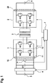
- FIG. 1 shows a schematic representation of a DC voltage converter according to an embodiment.
- the DC voltage converter is, in particular, a bidirectional DC voltage converter, that is to say the DC voltage converter can optionally convert an electrical voltage in one direction or the other.
- the DC voltage converter can be electrically connected to a first DC voltage network at a first DC voltage connection 10.
- This first DC voltage network can be, for example, a high-voltage on-board network of an electric or hybrid vehicle.
- the first DC voltage network is exemplified by a first DC voltage source 5, which is connected to the first DC voltage connection 10 of the DC voltage converter via a circuit breaker 4 connected is.
- a first capacitor C1 and a first full bridge 1 are connected to the first DC voltage connection 10.
- the first full bridge 1 comprises two half bridges 11 and 12.
- the first half bridge 11 has an upper switching element M1 and a lower switching element M3.
- the second half bridge 12 also has an upper switching element M2 and a lower switching element M4.
- the upper switching elements M1 and M2 are here, for example, connected to the positive connection element of the DC voltage connection 10.
- the lower switching elements M3 and M4 are correspondingly connected to the negative connection element of the first DC voltage connection 10.
- the connection nodes between the upper switching elements M1 and M2 and the lower switching elements M3 and M4 are connected to one side, for example the primary side, of a transformer 3.
- the DC voltage converter comprises a second full bridge 2, which is optionally connected to a second DC voltage connection 20 together with a second capacitor C2.
- This second DC voltage connection 20 can be connected to a further DC voltage network, for example a low-voltage on-board network of an electric or hybrid vehicle.
- This second DC voltage network is shown here by way of example by the second DC voltage source 6.
- Analogously to the first full bridge 1, the second full bridge 2 is connected to a further side of the transformer 3, for example a secondary side of the transformer 3.
- the control of the DC voltage converter in particular the control of the switching elements in the first full bridge 1 and the second full bridge 2, takes place by means of a control device 7.
- a diagnosis of the switching elements M1 to M4 can be carried out.
- an electrical voltage across the first capacitor C1 can be detected by means of a voltage sensor 71.
- the DC voltage converter is electrically connected at the second DC voltage connection 20 to a voltage source 6, for example a low-voltage electrical system of a vehicle.
- a voltage source 6 for example a low-voltage electrical system of a vehicle.
- the first DC voltage connection 10 is decoupled from further electrical loads.
- the disconnector 4 can be opened.
- the control device 7 can, for example, provide a corresponding control signal to the isolating switch 4.
- switching elements M1 to M4 with the half bridges 11 and 12 of the first full bridge 1 are opened by a corresponding control, for example by means of control signals from the control device 7.
- the second full bridge 2 in particular the switching elements M5 to M8 of the second full bridge 2, is then activated by the control device 7.
- an alternating voltage is provided on the secondary side of the transformer 3.
- the AC voltage then induced on the primary side of the transformer 3 is rectified via the diodes arranged in parallel with the switching elements M1 to M4 of the first full bridge 1 and then charges the first capacitor C1.
- the first capacitor C1 can be charged to a predetermined test voltage Up in this way.
- the control of the second full bridge 2 is ended. Then an upper switching element M1 or M2 is closed in one of the two half bridges 11 or 12, while the other three switching elements stay open.
- the first switching element M1 can be closed while the switching elements M2 to M4 remain open.
- the first capacitor C1 will not discharge and the electrical voltage across the first capacitor C1 will remain almost constant.
- the voltage profile across the first capacitor C1 can be detected, for example, by means of the voltage sensor 71 and made available to the control device 7. If the electrical voltage across the first capacitor C1 remains approximately constant during a predetermined period of time ⁇ t, that is, if the electrical voltage across the first capacitor C1 falls by less than a predetermined threshold value, it can be assumed that the lower switching elements M3 and M4 of the two half bridges 11 and 12 in the first full bridge 1 can ensure a sufficiently high level of isolation.
- the electrical voltage across the first capacitor C1 will drop very quickly. In this case, this voltage drop can be detected by the voltage sensor 71.
- the first capacitor C1 will discharge via the deliberately closed switching element M1, the primary side of the transformer 3 and the defective switching element M4. In this case, the first capacitor C1 is also discharged, but more slowly than in the case in which the faulty lower switching element and the deliberately closed upper switching element are in the same half-bridge. In this case, therefore, the voltage across the first capacitor C1 will drop less sharply within a predetermined period of time.
- the lower switching elements M3 and M4 ensure adequate separation in the open state, or whether one of the two lower switching elements M3 or M4 cannot guarantee adequate electrical separation.
- the electrical voltage across the first capacitor C1 with a first predetermined limit value and possibly a second predetermined limit value, it can then be determined whether one of the two lower switching elements M3 or M4 is faulty. If necessary, a statement can be made about which of the two switching elements M3 or M4 is faulty from the level of the voltage drop within the predetermined time period ⁇ t.
- the diagnosis can already be ended at this point in time. Otherwise, or if the upper switching elements M1 and M3 are also to be checked, a corresponding diagnosis can then be carried out for the two upper switching elements M1 and M2.
- the first capacitor C1 can optionally be charged again.
- the first capacitor C1 can be charged again to the specified test voltage Up by appropriately activating the switching elements in the second full bridge 2.
- a lower switching element M3 or M4 is closed for the diagnosis of the upper switching elements M1 and M2, while all the other switching elements are opened.
- the lower switching element M3 in the first half bridge 11 can be closed for this purpose, while the upper switching elements M1 and M2 and the further lower switching element M4 remain open.
- the voltage profile across the first capacitor C1 is then evaluated again during a predetermined period of time. If the voltage drop across the first capacitor C1 remains below a predetermined voltage drop, the upper switching elements M1 and M2 can also be classified as functional. If, on the other hand, the electrical voltage across the first capacitor C1 falls below a predetermined limit value, then at least one of the two upper switching elements M1 and M2 is defective.
- FIG. 2 shows a schematic representation of a voltage-time course during a diagnosis of a DC-DC converter according to an embodiment.
- the capacitor C1 is initially charged to the specified test voltage Up.
- the voltage across the first capacitor C1 reaches the specified test voltage Up.
- the charging of the first capacitor C1 is then ended and the voltage profile across the first capacitor C1 is monitored. If, after a predetermined time period ⁇ t at time t2, the electrical voltage across the first capacitor C1 is still above a predetermined first limit value U1, then the switching elements to be checked can be classified as intact. If the electrical voltage across the first capacitor C1 is below the first predetermined limit voltage U1, then at least one of the switching elements to be checked is defective. If the electrical voltage across the first capacitor C1 drops below a predetermined second voltage value U2, this is an indication that the faulty switching element and the deliberately closed switching element are in the same half-bridge.
- the other switching elements can then also be checked.
- the electrical voltage across the first capacitor C1 can optionally be recharged to the test voltage Up. If this is reached at time t3, then the voltage profile across the first capacitor C1 is monitored again during a predetermined period of time .DELTA.t. If the voltage at time t4 is still above the specified limit voltage U1, then the switching elements checked here are also intact. If, on the other hand, the voltage has fallen below the specified limit voltage U1, then at least one of the switching elements to be checked is faulty. If the voltage across the first capacitor C1 falls below a lower, second limit voltage U2, this is again an indication that the purposely closed switching element and the faulty switching element are in the same half-bridge.
- Figure 3 shows a schematic representation of a flowchart on the basis of a diagnostic method for a DC voltage converter according to an embodiment.
- the diagnosis procedure described below essentially corresponds to the diagnosis as already described above.
- step S1 a first DC voltage is initially provided at the second DC voltage connection 20 of the DC voltage converter and in step S2 all first switching elements M1, M2 and second switching elements M3, M4 in the first full bridge 1 of the DC voltage converter are opened.
- step S3 the first capacitor C1 is then charged to a predetermined test voltage Up by driving the second full bridge 2.
- One of the first switching elements M1, M2 in the first full bridge 1 is then closed in step S4. If the electrical voltage across the first capacitor C1 falls by more than a predetermined first voltage value within a predetermined first time span ⁇ t after the first switching element M1, M2 has closed, a faulty second switching element can be detected in step S5. In this case, the method can be ended because a defective switching element has already been detected.
- step S6 the closed first switching element M1, M2 of the first full bridge 1 is opened and switched on second switching element M3 or M4 in the first full bridge 1 is closed. If the electrical voltage across the first capacitor C1 then falls by more than a predetermined voltage value within a predetermined second period of time after the closing of the second switching element M3 or M4 in step S7, a faulty first switching element M1, M2 can thereby be detected in step S8 .
- the electrical voltage to which the first capacitor C1 is charged can be limited.
- the maximum electrical voltage to which the first capacitor C1 is charged can be determined as a function of a maximum permissible forward current of the switching elements M1 to M4 in the first full bridge 1, a maximum operating temperature and / or a maximum heat dissipation of the switching elements M1 to M4 .
- the present invention relates to the diagnosis of the switching elements in a bidirectional DC voltage converter.
- a capacitor in the DC voltage converter By charging a capacitor in the DC voltage converter and then specifically controlling the switching elements and evaluating the voltage in the charged capacitor of the DC voltage converter, it is possible to identify a defective switching element.
Description
Die vorliegende Erfindung betrifft ein Diagnoseverfahren für einen Gleichspannungskonverter, einen Gleichspannungskonverter und eine Spannungsversorgungseinrichtung mit einem Gleichspannungskonverter. Insbesondere betrifft die vorliegende Erfindung die Diagnose von bidirektionalen Gleichspannungskonvertern.The present invention relates to a diagnostic method for a DC voltage converter, a DC voltage converter and a voltage supply device with a DC voltage converter. In particular, the present invention relates to the diagnosis of bidirectional DC voltage converters.
Die Druckschrift
Bei Kraftfahrzeugen mit Elektro- oder Hybridantrieb wird die elektrische Energie für den elektrischen Antrieb von einer Hochvoltbatterie bereitgestellt. Gleichzeitig weisen viele Kraftfahrzeuge elektrische Geräte auf, die konstante Niedervoltspannungen benötigen. Dabei sind die Hochvoltspannungen des elektrischen Antriebssystems im Allgemeinen deutlich höher als die Niedervoltspannungen der weiteren elektrischen Verbraucher. Um die Niedervoltgeräte ebenfalls mit Energie aus dem Hochvoltnetz zu versorgen und gegebenenfalls auch eine Batterie auf der Niedervoltseite aufzuladen, wird daher eine Schaltungsanordnung verwendet, welche eine elektrische Energieübertragung zwischen Hochvoltseite und Niedervoltseite ermöglicht.In motor vehicles with an electric or hybrid drive, the electrical energy for the electric drive is provided by a high-voltage battery. At the same time, many motor vehicles have electrical devices that require constant low-voltage voltages. The high-voltage voltages of the electrical drive system are generally significantly higher than the low-voltage voltages of the other electrical consumers. In order to also supply the low-voltage devices with energy from the high-voltage network and, if necessary, also to charge a battery on the low-voltage side, a circuit arrangement is used which enables electrical energy to be transmitted between the high-voltage side and the low-voltage side.
Für einen ordnungsgemäßen Betrieb eines solchen Gleichspannungswandlers, wie er zum Beispiel zwischen einer Hochvoltseite und einer Niedervoltseite eines Elektro- oder Hybridfahrzeugs eingesetzt wird, sollte sichergestellt werden, dass die Bauelemente dieses Gleichspannungswandlers, insbesondere die dabei verwendeten Schaltelemente, ordnungsgemäß funktionieren.For proper operation of such a DC / DC converter, such as that used between a high-voltage side and a low-voltage side of an electric or hybrid vehicle, it should be ensured that the components of this DC / DC converter, in particular the switching elements used, function properly.
Die vorliegende Erfindung offenbart ein Diagnoseverfahren für einen bidirektionalen Gleichspannungskonverter mit den Merkmalen des Patentanspruchs 1, einen Gleichspannungskonverter mit den Merkmalen des Patentanspruchs 7 und eine Spannungsversorgungseinrichtung für ein Elektro- oder Hybridfahrzeug mit den Merkmalen des Patentanspruchs 8.The present invention discloses a diagnostic method for a bidirectional DC voltage converter with the features of claim 1, a DC voltage converter with the features of claim 7 and a voltage supply device for an electric or hybrid vehicle with the features of claim 8.
Ein Diagnoseverfahren für einen bidirektionalen Gleichspannungskonverter. Der Gleichspannungskonverter weist einen ersten Gleichspannungsanschluss und einen zweiten Gleichspannungsanschluss auf. An dem ersten Gleichspannungsanschluss umfasst der Gleichspannungskonverter einen ersten Kondensator und eine erste Vollbrücke. An dem zweiten Gleichspannungsanschluss umfasst der Gleichspannungskonverter eine zweite Vollbrücke. Die erste Vollbrücke und die zweite Vollbrücke können mittels eines Transformators oder ähnlichem miteinander gekoppelt werden. Die Vollbrücken, insbesondere die erste Vollbrücke, umfassen zwei Halbbrücken mit jeweils einem ersten Schaltelement und einem zweiten Schaltelement. Das Verfahren umfasst die Schritte des Bereitstellens einer ersten Gleichspannung an den zweiten Gleichspannungsanschluss des Gleichspannungskonverters und des Öffnens aller ersten Schaltelemente und aller zweiten Schaltelemente in der ersten Vollbrücke des Gleichspannungskonverters. Weiterhin umfasst das Verfahren einen Schritt zum Aufladen des ersten Kondensators auf eine vorbestimmte erste Prüfspannung. Der erste Kondensator wird hierbei durch Ansteuern der zweiten Vollbrücke auf die vorbestimmte erste Prüfspannung aufgeladen. Daraufhin umfasst das Verfahren einen Schritt zum Schließen eines ersten Schaltelements in der ersten Vollbrücke und des anschließenden Detektierens eines fehlerhaften zweiten Schaltelements, falls die elektrische Spannung über dem ersten Kondensator innerhalb einer vorbestimmten ersten Zeitspanne nach dem Schließen des ersten Schaltelements um mehr als einen vorgegebenen ersten Spannungswert absinkt. Falls ein fehlerhaftes zweites Schaltelement detektiert worden ist, kann das Verfahren gegebenenfalls daraufhin beendet werden. Ferner umfasst das Verfahren einen Schritt zum Öffnen des geschlossenen ersten Schaltelements in der ersten Vollbrücke und einen Schritt zum Schließen eines zweiten Schaltelements in der ersten Vollbrücke. Daraufhin umfasst das Verfahren einen Schritt zum Detektieren eines fehlerhaften ersten Schaltelements, falls die elektrische Spannung über dem ersten Kondensator innerhalb einer vorbestimmten zweiten Zeitspanne nach dem Schließen des zweiten Schaltelements um mehr als einen vorgegebenen zweiten Spannungswert absinkt. Wird weder ein fehlerhaftes erstes Schaltelement noch ein fehlerhaftes zweites Schaltelement detektiert, so können die ersten und zweiten Schaltelemente in der Vollbrücke als fehlerfrei klassifiziert werden.A diagnostic method for a bidirectional DC voltage converter. The DC voltage converter has a first DC voltage connection and a second DC voltage connection. At the first DC voltage connection, the DC voltage converter comprises a first capacitor and a first full bridge. The DC voltage converter comprises a second full bridge at the second DC voltage connection. The first full bridge and the second full bridge can be coupled to one another by means of a transformer or the like. The full bridges, in particular the first full bridge, comprise two half bridges, each with a first switching element and a second switching element. The method comprises the steps of providing a first DC voltage to the second DC voltage connection of the DC voltage converter and opening all first switching elements and all second switching elements in the first full bridge of the DC voltage converter. The method further comprises a step of charging the first capacitor to a predetermined first test voltage. The first capacitor is hereby controlled by the second Full bridge charged to the predetermined first test voltage. The method then includes a step of closing a first switching element in the first full bridge and then detecting a faulty second switching element if the electrical voltage across the first capacitor exceeds a predetermined first voltage value within a predetermined first time span after the first switching element has closed sinks. If a faulty second switching element has been detected, the method can then be ended if necessary. The method further comprises a step of opening the closed first switching element in the first full bridge and a step of closing a second switching element in the first full bridge. The method then comprises a step of detecting a faulty first switching element if the electrical voltage across the first capacitor falls by more than a predetermined second voltage value within a predetermined second time span after the second switching element has closed. If neither a faulty first switching element nor a faulty second switching element is detected, the first and second switching elements in the full bridge can be classified as faultless.
Ein Gleichspannungskonverter für eine bidirektionale Gleichspannungskonvertierung zwischen einem ersten Gleichspannungsanschluss und einem zweiten Gleichspannungsanschluss. Der Gleichspannungskonverter umfasst einen ersten Kondensator, eine erste Vollbrücke, eine zweite Vollbrücke und eine Steuereinrichtung. Die erste Vollbrücke und die zweite Vollbrücke können mittels eines Transformators oder ähnlichem miteinander gekoppelt werden. Der erste Kondensator ist mit dem ersten Gleichspannungsanschluss des Gleichspannungskonverters elektrisch gekoppelt. Die erste Vollbrücke ist ebenfalls mit dem ersten Gleichspannungsanschluss elektrisch gekoppelt. Die erste Vollbrücke umfasst zwei Halbbrücken mit jeweils einem ersten Schaltelement und einem zweiten Schaltelement. Die zweite Vollbrücke ist mit dem zweiten Gleichspannungsanschluss elektrisch gekoppelt. Die Steuereinrichtung ist dazu ausgelegt, die ersten Schaltelemente und die zweiten Schaltelemente in der ersten Vollbrücke zu öffnen und den Kondensator durch Ansteuern der zweiten Vollbrücke auf eine vorbestimmte erste Prüfspannung aufzuladen und anschließend eines der ersten Schaltelemente in der ersten Vollbrücke zu schließen. Weiterhin ist die Steuereinrichtung dazu ausgelegt, ein fehlerhaftes zweites Schaltelement in der ersten Vollbrücke zu detektieren, falls die elektrische Spannung über dem ersten Kondensator innerhalb einer vorbestimmten ersten Zeitspanne nach dem Schließen des ersten Schaltelements um mehr als einen vorgegebenen ersten Spannungswert absinkt. Weiterhin ist die Steuereinrichtung dazu ausgelegt, anschließend das geschlossene erste Schaltelement in der ersten Vollbrücke zu öffnen und ein zweites Schaltelement in der ersten Vollbrücke zu schließen, sowie ein fehlerhaftes erstes Schaltelement zu detektieren, falls die elektrische Spannung über dem ersten Kondensator innerhalb einer vorbestimmten zweiten Zeitspanne nach dem Schließen des zweiten Schaltelements um mehr als einen vorgegebenen zweiten Spannungswert absinkt. Sollte zuvor bereits ein fehlerhaftes zweites Schaltelement detektiert worden sein, so kann das Detektieren eines fehlerhaften ersten Schaltelements sowie das vorherige Öffnen des ersten Schaltelements und das Schließen des zweiten Schaltelements übersprungen werden.A DC voltage converter for bidirectional DC voltage conversion between a first DC voltage connection and a second DC voltage connection. The DC voltage converter comprises a first capacitor, a first full bridge, a second full bridge and a control device. The first full bridge and the second full bridge can be coupled to one another by means of a transformer or the like. The first capacitor is electrically coupled to the first DC voltage connection of the DC voltage converter. The first full bridge is also electrically coupled to the first DC voltage connection. The first full bridge comprises two half bridges, each with a first switching element and a second switching element. The second full bridge is electrically coupled to the second DC voltage connection. The control device is designed to control the first switching elements and the second switching elements in the to open the first full bridge and to charge the capacitor to a predetermined first test voltage by driving the second full bridge and then to close one of the first switching elements in the first full bridge. Furthermore, the control device is designed to detect a faulty second switching element in the first full bridge if the electrical voltage across the first capacitor drops by more than a predetermined first voltage value within a predetermined first time span after the first switching element has closed. Furthermore, the control device is designed to subsequently open the closed first switching element in the first full bridge and to close a second switching element in the first full bridge, as well as to detect a faulty first switching element if the electrical voltage across the first capacitor is within a predetermined second period of time after the closing of the second switching element drops by more than a predetermined second voltage value. If a faulty second switching element has already been detected beforehand, the detection of a faulty first switching element as well as the previous opening of the first switching element and the closing of the second switching element can be skipped.
Eine Spannungsversorgungseinrichtung für ein Elektro- oder Hybridfahrzeug mit einem Hochvolt-Bordnetz, einem Niedervolt-Bordnetz und einem erfindungsgemäßen Gleichspannungskonverter. Das Hochvolt-Bordnetz ist dazu ausgelegt, elektrische Energie mit einer ersten vorbestimmten elektrischen Spannung bereitzustellen. Das Niedervolt-Bordnetz ist dazu ausgelegt, elektrische Energie mit einer zweiten vorbestimmten elektrischen Spannung bereitzustellen. Der erste Gleichspannungsanschluss des Gleichspannungskonverters ist mit dem Hochvolt-Bordnetz elektrisch koppelbar. Der zweite Gleichspannungsanschluss des Gleichspannungskonverters ist elektrisch mit dem Niedervolt-Bordnetz gekoppelt. Insbesondere kann es sich beim dem Hochvolt-Bordnetz um ein Bordnetz zur Spannungsversorgung eines elektrischen Antriebssystems in dem Elektro- oder Hybridfahrzeug handeln. Bei dem Niedervolt-Bordnetz kann es sich um ein Bordnetz zur Versorgung elektrischer Verbraucher handeln. Das Niedervolt-Bordnetz kann insbesondere im Bereich von 12 Volt, 24 Volt oder 48 Volt betrieben werden.A voltage supply device for an electric or hybrid vehicle with a high-voltage on-board network, a low-voltage on-board network and a DC voltage converter according to the invention. The high-voltage on-board electrical system is designed to provide electrical energy with a first predetermined electrical voltage. The low-voltage vehicle electrical system is designed to provide electrical energy with a second predetermined electrical voltage. The first DC voltage connection of the DC voltage converter can be electrically coupled to the high-voltage vehicle electrical system. The second DC voltage connection of the DC voltage converter is electrically coupled to the low-voltage vehicle electrical system. In particular, the high-voltage on-board network can be an on-board network for supplying voltage to an electric drive system in the electric or hybrid vehicle. The low-voltage on-board network can be an on-board network for supply act as electrical consumers. The low-voltage vehicle electrical system can be operated in the range of 12 volts, 24 volts or 48 volts.
Der vorliegenden Erfindung liegt die Erkenntnis zugrunde, dass ein fehlerhaftes Schaltelement in einem Gleichspannungskonverter, insbesondere auf einer Hochvoltseite eines Gleichspannungskonverters gegebenenfalls keine zuverlässige elektrische Trennung ermöglichen kann. In diesem Fall bleibt eine elektrische Verbindung zwischen den Anschlüssen des Schaltelements auch dann zumindest teilweise aufrechterhalten, wenn das Schaltelement geöffnet sein sollte. Während des Betriebs des Gleichspannungskonverters kann dabei über ein solches fehlerhaftes Schaltelement eine unerwünschte elektrische Verbindung hergestellt werden, die gegebenenfalls zu einem Kurzschluss führen kann. Durch einen derartigen Kurzschluss können hohe elektrische Ströme fließen, die zu weiteren Beschädigungen und gegebenenfalls zu einem thermischen Ereignis führen können.The present invention is based on the knowledge that a defective switching element in a DC voltage converter, in particular on a high-voltage side of a DC voltage converter, may possibly not enable reliable electrical isolation. In this case, an electrical connection between the connections of the switching element is at least partially maintained even if the switching element should be open. During the operation of the DC voltage converter, an undesired electrical connection can be established via such a faulty switching element, which can possibly lead to a short circuit. Such a short circuit can cause high electrical currents to flow, which can lead to further damage and possibly to a thermal event.
Der vorliegenden Erfindung liegt daher die Idee zugrunde, dieser Erkenntnis Rechnung zu tragen und eine Diagnose für die Schaltelemente eines Gleichspannungskonverters, insbesondere für die Schaltelemente auf der Hochvoltseite eines Gleichspannungskonverters bereitzustellen. Wird ein solches fehlerhaftes Schaltelement in dem Gleichspannungskonverter frühzeitig erkannt, so können daraufhin Maßnahmen eingeleitet werden, die weitere gefährliche Betriebszustände, wie zum Beispiel einen Kurzschluss und ein damit verbundenes thermisches Ereignis verhindern können. Auf diese Weise kann die Sicherheit des Gleichspannungskonverters und damit des gesamten Systems gesteigert werden.The present invention is therefore based on the idea of taking this knowledge into account and providing a diagnosis for the switching elements of a DC voltage converter, in particular for the switching elements on the high-voltage side of a DC voltage converter. If such a faulty switching element is detected early in the DC voltage converter, measures can then be initiated which can prevent further dangerous operating states, such as a short circuit and an associated thermal event. In this way, the safety of the DC converter and thus of the entire system can be increased.
Für die Diagnose des Gleichspannungskonverters kann dabei die verwendete elektrische Energie insbesondere so weit begrenzt werden, dass während der Diagnose keine übermäßige Belastung der beteiligten Bauelemente auftritt. Auf diese Weise können fehlerhafte Schaltelemente identifiziert werden, ohne dass dabei weitere Bauelemente mit in Leidenschaft gezogen werden.For the diagnosis of the DC voltage converter, the electrical energy used can in particular be limited to such an extent that the components involved are not subjected to excessive loading during the diagnosis. In this way, faulty switching elements can be identified without further components being drawn into passion.
Gemäß einer Ausführungsform werden die Schritte des Öffnens des geschlossenen ersten Schaltelements, des Schließens eines geöffneten zweiten Schaltelements und des Detektierens eines fehlerhaften ersten Schaltelements nur dann ausgeführt, falls zuvor kein fehlerhaftes zweites Schaltelement detektiert worden ist. Falls bereits zuvor ein fehlerhaftes zweites Schaltelement bereits detektiert worden ist, so ergibt sich hierdurch, dass ein ordnungsgemäßer Betrieb des Gleichspannungskonverters nicht möglich ist und somit ein fehlerfreier Betrieb des Gleichspannungskonverters nicht ausgeführt werden kann. Daher kann bereits eine Fehlermeldung ausgegeben werden, ohne dass weitere Schritte zur Diagnose ausgeführt werden müssen.According to one embodiment, the steps of opening the closed first switching element, closing an opened second switching element and detecting a faulty first switching element are only carried out if no faulty second switching element has previously been detected. If a faulty second switching element has already been detected beforehand, this means that proper operation of the DC voltage converter is not possible and therefore error-free operation of the DC voltage converter cannot be carried out. This means that an error message can already be output without further diagnostic steps having to be carried out.
Gemäß einer Ausführungsform umfasst das Verfahren einen Schritt zum Aufladen des ersten Kondensators auf eine vorbestimmte zweite Spannung, nachdem das geschlossene erste Schaltelement geöffnet worden ist. Insbesondere kann die vorbestimmte zweite Spannung beispielsweise der vorbestimmten ersten Spannung entsprechen. Auf diese Weise kann auch nach der Überprüfung der zweiten Schaltelemente der erste Kondensator erneut auf eine elektrische Spannung aufgeladen werden, die eine zuverlässige Überprüfung der ersten Schaltelemente ermöglicht. Gegebenenfalls kann das Aufladen des ersten Kondensators nach der Überprüfung der zweiten Schaltelemente nur dann ausgeführt werden, falls die elektrische Spannung über dem ersten Kondensator einen vorgegebenen Grenzwert unterschritten hat.According to one embodiment, the method comprises a step of charging the first capacitor to a predetermined second voltage after the closed first switching element has been opened. In particular, the predetermined second voltage can correspond to the predetermined first voltage, for example. In this way, even after the second switching elements have been checked, the first capacitor can be charged again to an electrical voltage which enables the first switching elements to be checked reliably. If necessary, the first capacitor can only be charged after the second switching elements have been checked if the electrical voltage across the first capacitor has fallen below a predetermined limit value.
Gemäß einer Ausführungsform werden die vorbestimmte erste Spannung und/oder gegebenenfalls auch die vorbestimmte zweite Spannung, auf die der erste Kondensator aufgeladen wird, in Abhängigkeit von einem maximalen Durchlassstrom, einer maximalen Betriebstemperatur und/oder einer maximalen Wärmedissipation der ersten Schaltelemente und/oder der zweiten Schaltelemente bestimmt. Auf diese Weise kann sichergestellt werden, dass die Schaltelemente während der Überprüfung auch in einem Fehlerfall nicht überlastet werden. Hierdurch kann eine mögliche Beschädigung weiterer Bauelemente verhindert werden.According to one embodiment, the predetermined first voltage and / or possibly also the predetermined second voltage to which the first capacitor is charged, depending on a maximum forward current, a maximum operating temperature and / or a maximum heat dissipation of the first switching elements and / or the second Switching elements determined. In this way it can be ensured that the switching elements are not overloaded during the check even in the event of a fault. This can prevent possible damage to other components.
Gemäß einer Ausführungsform ist der Wert der ersten Prüfspannung, auf die der erste Kondensator vor der Überprüfung der Schaltelemente aufgeladen wird, größer als der Wert der ersten Gleichspannung, die an dem zweiten Gleichspannungsanschluss bereitgestellt wird. Auf diese Weise können die Schaltelemente auf der Hochvoltseite des Gleichspannungskonverters durch das Bereitstellen einer geringeren Spannung auf der Niedervoltseite des Gleichspannungskonverters überprüft werden. Die elektrische Spannung, auf die der erste Kondensator dabei aufgeladen wird, kann beispielsweise einer elektrischen Spannung entsprechen, welche in einem Gleichspanungsnetz anliegt, mit welchem der Gleichspannungskonverter an dem ersten Gleichspannungsanschluss koppelbar ist. Alternativ kann die elektrische Spannung, auf die der erste Kondensator aufgeladen wird auch niedriger sein, als die elektrische Spannung des Gleichspannungsnetzes, mit dem der erste Gleichspannungsanschluss koppelbar ist.According to one embodiment, the value of the first test voltage to which the first capacitor is charged before the switching elements are checked is greater than the value of the first direct voltage that is provided at the second direct voltage connection. In this way, the switching elements on the high-voltage side of the DC voltage converter can be checked by providing a lower voltage on the low-voltage side of the DC voltage converter. The electrical voltage to which the first capacitor is charged can correspond, for example, to an electrical voltage which is present in a DC voltage network with which the DC voltage converter can be coupled to the first DC voltage connection. Alternatively, the electrical voltage to which the first capacitor is charged can also be lower than the electrical voltage of the DC voltage network to which the first DC voltage connection can be coupled.
Gemäß einer Ausführungsform umfasst das Verfahren einen Schritt zum Freigeben des Gleichspannungskonverters, falls kein fehlerhaftes erstes Schaltelement und kein fehlerhaftes zweites Schaltelement detektiert worden ist. Auf diese Weise kann sichergestellt werden, dass der Gleichspannungskonverter nur dann betrieben wird, wenn zuvor eine Überprüfung der Schaltelemente in dem Gleichspannungskonverter ausgeführt worden ist.According to one embodiment, the method comprises a step of enabling the DC voltage converter if no faulty first switching element and no faulty second switching element have been detected. In this way it can be ensured that the DC voltage converter is only operated if the switching elements in the DC voltage converter have been checked beforehand.
Erfindungsgemäß umfasst der Gleichspannungskonverter einen Transformator. Der Transformator ist mit einer Primärseite mit der ersten Vollbrücke elektrisch gekoppelt und mit einer Sekundärseite mit der zweiten Vollbrücke elektrisch gekoppelt. Auf diese Weise kann eine galvanische Trennung zwischen der ersten Vollbrücke und der zweiten Vollbrücke erreicht werden. Darüber hinaus kann gegebenenfalls entsprechend dem Übertragungsverhältnis des Transformators die Spannungshöhe während der Gleichspannungswandlung eingestellt werden.According to the invention, the DC voltage converter comprises a transformer. The transformer is electrically coupled to the first full bridge on a primary side and electrically coupled to the second full bridge on a secondary side. In this way, a galvanic separation between the first full bridge and the second full bridge can be achieved. In addition, the voltage level during the DC voltage conversion can optionally be set according to the transmission ratio of the transformer.
Bei den Schaltelementen des Wechselrichters kann es sich insbesondere beispielsweise um Halbleiterschaltelemente, wie zum Beispiel bipolare Transistoren mit einem isolierten Gateanschluss (IGBT) oder MOSFET handeln.The switching elements of the inverter can be, for example, semiconductor switching elements, such as bipolar transistors with an insulated gate connection (IGBT) or MOSFET.
Die obigen Ausgestaltungen und Weiterbildungen lassen sich, soweit sinnvoll, beliebig miteinander kombinieren. Weitere Ausgestaltungen, Weiterbildungen und Implementierungen der Erfindung umfassen auch nicht explizit genannte Kombinationen von zuvor oder im Folgenden bezüglich den Ausführungsbeispielen beschriebenen Merkmalen der Erfindung.The above configurations and developments can be combined with one another as desired, as far as this makes sense. Further refinements, developments and implementations of the invention also include not explicitly mentioned Combinations of features of the invention described above or below with respect to the exemplary embodiments.
Die vorliegende Erfindung wird nachfolgend anhand der in den schematischen Figuren der Zeichnungen angegebenen Ausführungsbeispiele näher erläutert Dabei zeigen:
- Fig. 1:
- eine schematische Darstellung eines Gleichspannungskonverters gemäß einer Ausführungsform;
- Fig. 2:
- eine schematische Darstellung eines Spannungs-Zeitdiagramms für den Spannungsverlauf während einer Diagnose eines Gleichspannungskonverters gemäß einer Ausführungsform; und
- Fig. 3:
- eine schematische Darstellung eines Ablaufdiagramms, wie es einem Diagnoseverfahren für einen Gleichspannungskonverters gemäß einer Ausführungsform zugrunde liegt.
- Fig. 1:
- a schematic representation of a DC converter according to an embodiment;
- Fig. 2:
- a schematic representation of a voltage-time diagram for the voltage profile during a diagnosis of a DC voltage converter according to an embodiment; and
- Fig. 3:
- a schematic representation of a flow chart as it is based on a diagnostic method for a DC voltage converter according to an embodiment.
Der Gleichspannungswandler ist an einem ersten Gleichspannungsanschluss 10 mit einem ersten Gleichspannungsnetz elektrisch verbindbar. Bei diesem ersten Gleichspannungsnetz kann es sich beispielsweise um ein Hochvolt-Bordnetz eines Elektro- oder Hybridfahrzeugs handeln. In der hier dargestellten Ausführungsform ist das erste Gleichspannungsnetz beispielhaft durch eine erste Gleichspannungsquelle 5 dargestellt, die über einen Trennschalter 4 mit dem ersten Gleichspannungsanschluss 10 des Gleichspannungskonverters verbunden ist. An dem ersten Gleichspannungsanschluss 10 ist ein erster Kondensator C1 und eine erste Vollbrücke 1 angeschlossen. Die erste Vollbrücke 1 umfasst in der hier dargestellten Ausführungsform zwei Halbbrücken 11 und 12. Die erste Halbbrücke 11 weist ein oberes Schaltelement M1 und ein unteres Schaltelement M3 auf. Ebenso weist die zweite Halbbrücke 12 ein oberes Schaltelement M2 und ein unteres Schaltelement M4 auf. Die oberen Schaltelemente M1 und M2 sind hier beispielsweise mit dem positiven Anschlusselement des Gleichspannungsanschlusses 10 verbunden. Die unteren Schaltelemente M3 und M4 sind entsprechend mit dem negativen Anschlusselement des ersten Gleichspannungsanschlusses 10 verbunden. Die Verbindungsknoten zwischen den oberen Schaltelementen M1 und M2 sowie den unteren Schaltelementen M3 und M4 sind mit einer Seite, beispielsweise der Primärseite, eines Transformators 3 verbunden.The DC voltage converter can be electrically connected to a first DC voltage network at a first
Weiterhin umfasst der Gleichspannungskonverter eine zweite Vollbrücke 2, die gegebenenfalls gemeinsam mit einem zweiten Kondensator C2 an einem zweiten Gleichspannungsanschluss 20 angeschlossen sind. Dieser zweite Gleichspannungsanschluss 20 kann mit einem weiteren Gleichspannungsnetz, beispielsweise einem Niedervolt-Bordnetz eines Elektro- oder Hybridfahrzeuges verbunden sein. Dieses zweite Gleichspannungsnetz ist hier exemplarisch durch die zweite Gleichspannungsquelle 6 dargestellt. Analog zu der ersten Vollbrücke 1 ist die zweite Vollbrücke 2 mit einer weiteren Seite des Transformators 3, beispielsweise einer Sekundärseite des Transformators 3 verbunden. Die Ansteuerung des Gleichspannungswandlers, insbesondere die Ansteuerung der Schaltelemente in der ersten Vollbrücke 1 und der zweiten Vollbrücke 2 erfolgt mittels einer Steuereinrichtung 7.Furthermore, the DC voltage converter comprises a second full bridge 2, which is optionally connected to a second
Um sicherzustellen, dass während des Betriebs des Gleichspannungswandlers die Schaltelemente M1 bis M4 der ersten Vollbrücke 1 eine ordnungsgemäße elektrische Trennung gewährleisten können, kann eine Diagnose der Schaltelemente M1 bis M4 ausgeführt werden. Hierzu kann beispielsweise mittels eines Spannungssensors 71 eine elektrische Spannung über dem ersten Kondensator C1 erfasst werden. Durch Aufladen des ersten Kondensats C1 auf eine vorgegebene Prüfspannung und anschließendes Einstellen von vorgegebenen Schaltzuständen in der ersten Vollbrücke 1 kann aus dem Spannungsverlauf über dem ersten Kondensator C1 eine Aussage über die Funktionsfähigkeit der Schaltelemente M1 bis M4 der ersten Vollbrücke 1 getroffen werden.In order to ensure that the switching elements M1 to M4 of the first full bridge 1 can ensure proper electrical isolation during the operation of the DC / DC converter, a diagnosis of the switching elements M1 to M4 can be carried out. For this purpose, for example, an electrical voltage across the first capacitor C1 can be detected by means of a
Im Folgenden wir der Ablauf der Diagnose der Schaltelemente M1 bis M4 in der ersten Vollbrücke 1 beschrieben.The sequence of the diagnosis of the switching elements M1 to M4 in the first full bridge 1 is described below.
Während der Diagnose der Schaltelemente M1 bis M4 in der ersten Vollbrücke 1 ist der Gleichspannungskonverter an dem zweiten Gleichspannungsanschluss 20 mit einer Spannungsquelle 6, beispielsweise einem Niedervolt-Bordnetz eines Fahrzeugs elektrisch verbunden. Weiterhin ist der erste Gleichspannungsanschluss 10 von weiteren elektrischen Verbrauchern entkoppelt. Beispielsweise kann der Trennschalter 4 geöffnet werden. Hierzu kann zum Beispiel die Steuereinrichtung 7 ein entsprechendes Ansteuersignal an dem Trennschalter 4 bereitstellen.During the diagnosis of the switching elements M1 to M4 in the first full bridge 1, the DC voltage converter is electrically connected at the second
Weiterhin werden die Schaltelemente M1 bis M4 mit den Halbbrücken 11 und 12 der ersten Vollbrücke 1 durch eine entsprechende Ansteuerung, beispielsweise mittels Ansteuersignalen der Steuereinrichtung 7, geöffnet.Furthermore, the switching elements M1 to M4 with the half bridges 11 and 12 of the first full bridge 1 are opened by a corresponding control, for example by means of control signals from the control device 7.
Anschließend wird die zweite Vollbrücke 2, insbesondere die Schaltelemente M5 bis M8 der zweiten Vollbrücke 2, durch die Steuereinrichtung 7 angesteuert. Hierdurch wird an der Sekundärseite des Transformators 3 eine Wechselspannung bereitgestellt. Die daraufhin an der Primärseite des Transformators 3 induzierte Wechselspannung wird über die parallel zu den Schaltelementen M1 bis M4 der ersten Vollbrücke 1 angeordneten Dioden gleichgerichtet und lädt daraufhin den ersten Kondensator C1 auf. Durch ein geeignetes Ansteuern der Schaltelemente M5 bis M8 in der zweiten Vollbrücke 2 kann auf diese Weise der erste Kondensator C1 auf eine vorgegebene Prüfspannung Up aufgeladen werden.The second full bridge 2, in particular the switching elements M5 to M8 of the second full bridge 2, is then activated by the control device 7. As a result, an alternating voltage is provided on the secondary side of the transformer 3. The AC voltage then induced on the primary side of the transformer 3 is rectified via the diodes arranged in parallel with the switching elements M1 to M4 of the first full bridge 1 and then charges the first capacitor C1. By suitably driving the switching elements M5 to M8 in the second full bridge 2, the first capacitor C1 can be charged to a predetermined test voltage Up in this way.
Nachdem der ersten Kondensator C1 auf die vorgegebene Prüfspannung Up aufgeladen worden ist, wird die Ansteuerung der zweiten Vollbrücke 2 beendet. Anschließend wird ein oberes Schaltelement M1 oder M2 in einer der beiden Halbbrücken 11 oder 12 geschlossen, während die übrigen drei Schaltelemente geöffnet bleiben. Beispielsweise kann das erste Schaltelement M1 geschlossen werden, während die Schaltelemente M2 bis M4 geöffnet bleiben.After the first capacitor C1 has been charged to the specified test voltage Up, the control of the second full bridge 2 is ended. Then an upper switching element M1 or M2 is closed in one of the two
Können die unteren Schaltelemente M3 und M4 in den Halbbrücken 11 und 12 der ersten Vollbrücke 1 in diesem Schaltzustand eine ausreichende Isolation gewährleisten, so wird sich der erste Kondensator C1 nicht entladen und die elektrische Spannung über dem ersten Kondensator C1 wird annähernd konstant aufrechterhalten bleiben. Hierzu kann der Spannungsverlauf über dem ersten Kondensator C1 beispielsweise mittels des Spannungssensors 71 erfasst und an der Steuereinrichtung 7 bereitgestellt werden. Bleibt die elektrische Spannung über dem ersten Kondensator C1 während einer vorgegebenen Zeitspanne Δt annähernd konstant, das heißt sinkt die elektrische Spannung über dem ersten Kondensator C1 um weniger als einen vorgegebenen Schwellwert ab, so kann davon ausgegangen werden, dass die unteren Schaltelemente M3 und M4 der beiden Halbbrücken 11 und 12 in der ersten Vollbrücke 1 eine ausreichend hohe Isolation gewährleisten können.If the lower switching elements M3 and M4 in the half bridges 11 and 12 of the first full bridge 1 can ensure adequate insulation in this switching state, the first capacitor C1 will not discharge and the electrical voltage across the first capacitor C1 will remain almost constant. For this purpose, the voltage profile across the first capacitor C1 can be detected, for example, by means of the
Ist dagegen das untere Schaltelement M3 in der Halbbrücke 11 defekt, in welcher das obere Schaltelement M1 gezielt geschlossen worden ist, so wird die elektrische Spannung über dem ersten Kondensator C1 sehr rasch abfallen. In diesem Fall kann durch den Spannungssensor 71 dieser Spannungsabfall detektiert werden.If, on the other hand, the lower switching element M3 in the half-
Befinden sich dagegen das gezielt geschlossene obere Schaltelement M1 und das fehlerhafte untere Schaltelement M4 in unterschiedlichen Halbbrücken 11, 12, so wird sich der erste Kondensator C1 über das gezielt geschlossene Schaltelement M1, die Primärseite des Transformators 3 und das fehlerhafte Schaltelement M4 entladen. In diesem Fall wird sich der erste Kondensator C1 ebenfalls entladen, jedoch langsamer, als in dem Fall, in dem sich das fehlerhafte untere Schaltelement und das gezielt geschlossene obere Schaltelement in der gleichen Halbbrücke befinden. In diesem Fall wird daher die Spannung über dem ersten Kondensator C1 innerhalb einer vorgegebenen Zeitspanne weniger starken absinken.If, on the other hand, the deliberately closed upper switching element M1 and the faulty lower switching element M4 are in
Entsprechend kann durch Auswertung des Spannungsverlaufs über dem ersten Kondensator C1 festgestellt werden, ob die unteren Schaltelemente M3 und M4 eine ausreichende Trennung in geöffnetem Zustand gewährleisten, oder ob eines der beiden unteren Schaltelemente M3 oder M4 keine ausreichende elektrische Trennung gewährleisten kann. Durch einen Vergleich der elektrischen Spannung über dem ersten Kondensator C1 mit einem ersten vorgegebenen Grenzwert und gegebenenfalls einem zweiten vorgegebenen Grenzwert kann daraufhin ermittelt werden, ob eines der beiden unteren Schaltelemente M3 oder M4 fehlerhaft ist. Gegebenenfalls kann aus der Höhe des Spannungsabfalls innerhalb der vorgegebenen Zeitspanne Δt eine Aussage darüber getroffen werden, welches der beiden Schaltelemente M3 bzw. M4 fehlerhaft ist.Correspondingly, by evaluating the voltage profile across the first capacitor C1, it can be determined whether the lower switching elements M3 and M4 ensure adequate separation in the open state, or whether one of the two lower switching elements M3 or M4 cannot guarantee adequate electrical separation. By comparing the electrical voltage across the first capacitor C1 with a first predetermined limit value and possibly a second predetermined limit value, it can then be determined whether one of the two lower switching elements M3 or M4 is faulty. If necessary, a statement can be made about which of the two switching elements M3 or M4 is faulty from the level of the voltage drop within the predetermined time period Δt.
Wird festgestellt, dass eines der beiden unteren Schaltelemente M3 oder M4 fehlerhaft ist, so kann die Diagnose zu diesem Zeitpunkt bereits beendet werden. Andernfalls, oder wenn auch zusätzlich die oberen Schaltelemente M1 und M3 überprüft werden sollen, kann daraufhin eine entsprechende Diagnose für die beiden oberen Schaltelemente M1 und M2 ausgeführt werden.If it is determined that one of the two lower switching elements M3 or M4 is faulty, the diagnosis can already be ended at this point in time. Otherwise, or if the upper switching elements M1 and M3 are also to be checked, a corresponding diagnosis can then be carried out for the two upper switching elements M1 and M2.
Hierzu kann gegebenenfalls der erste Kondensator C1 erneut aufgeladen werden. Beispielsweise kann der erste Kondensator C1 durch entsprechendes Ansteuern der Schaltelemente in der zweiten Vollbrücke 2 erneut auf die vorgegebene Prüfspannung Up aufgeladen werden.For this purpose, the first capacitor C1 can optionally be charged again. For example, the first capacitor C1 can be charged again to the specified test voltage Up by appropriately activating the switching elements in the second full bridge 2.
Alternativ ist es auch möglich, falls die elektrische Spannung über dem ersten Kondensator C1 sich noch oberhalb eines vorgegebenen Grenzwertes befindet, auf ein erneutes Aufladen des ersten Kondensators C1 zu verzichten und mit der verbleibenden Restspannung in dem Kondensator C1 die weitere Diagnose auszuführen. Unabhängig davon, ob der erste Kondensator C1 erneut aufgeladen worden ist oder nicht, wird für die Diagnose der oberen Schaltelemente M1 und M2 ein unteres Schaltelement M3 oder M4 geschlossen, während alle anderen Schaltelemente geöffnet werden. Beispielsweise kann hierzu das untere Schaltelement M3 in der ersten Halbbrücke 11 geschlossen werden, während die oberen Schaltelemente M1 und M2, sowie das weitere untere Schaltelement M4 geöffnet bleiben.Alternatively, if the electrical voltage across the first capacitor C1 is still above a predetermined limit value, it is not necessary to recharge the first capacitor C1 and carry out the further diagnosis with the remaining voltage in the capacitor C1. Regardless of whether the first capacitor C1 has been charged again or not, a lower switching element M3 or M4 is closed for the diagnosis of the upper switching elements M1 and M2, while all the other switching elements are opened. For example, the lower switching element M3 in the
Daraufhin erfolgt erneut eine Auswertung des Spannungsverlaufs über dem ersten Kondensator C1 während einer vorbestimmten Zeitspanne. Bleibt dabei der Spannungsabfall über dem ersten Kondensator C1 unterhalb eines vorgegebenen Spannungsabfalls, so können auch die oberen Schaltelemente M1 und M2 als funktionsfähig klassifiziert werden. Fällt dagegen die elektrische Spannung über dem ersten Kondensator C1 unterhalb einen vorgegebenen Grenzwert, so ist mindestens eines der beiden oberen Schaltelemente M1 und M2 fehlerhaft. Auch hierbei kann basierend auf der Höhe des Spannungsabfalls über dem ersten Kondensator C1 während der vorbestimmten Zeitspanne darauf geschlossen werden, ob das obere Schaltelement M1, M2 in der gleichen Halbbrücke 11, 12, in der auch das gezielt geschlossene untere Schaltelemente M3, M4 liegt, fehlerhaft ist, oder ob sich das gezielt geschlossene untere Schaltelemente M3, M4 und das fehlerhafte obere Schaltelement M1, M2 in unterschiedlichen Halbbrücken 11, 12 befinden.The voltage profile across the first capacitor C1 is then evaluated again during a predetermined period of time. If the voltage drop across the first capacitor C1 remains below a predetermined voltage drop, the upper switching elements M1 and M2 can also be classified as functional. If, on the other hand, the electrical voltage across the first capacitor C1 falls below a predetermined limit value, then at least one of the two upper switching elements M1 and M2 is defective. Here, too, based on the level of the voltage drop across the first capacitor C1 during the predetermined period of time, it can be concluded whether the upper switching element M1, M2 is in the same half-
Ist kein fehlerhaftes Schaltelement klassifiziert worden, so können daraufhin auch die weiteren Schaltelemente überprüft werden. Wurden beispielsweise zunächst die unteren Schaltelemente M3 und M4 überprüft, so können anschließend die oberen Schaltelemente M1 und M2 überprüft werden. Hierzu kann gegebenenfalls die elektrische Spannung über dem ersten Kondensator C1 erneut auf die Prüfspannung Up aufgeladen werden. Ist dies zum Zeitpunkt t3 erreicht, so wird während einer vorgegebenen Zeitspanne Δt erneut der Spannungsverlauf über dem ersten Kondensator C1 überwacht. Ist die Spannung zum Zeitpunkt t4 noch oberhalb der vorgegebenen Grenzspannung U1, so sind auch die hierbei überprüften Schaltelemente intakt. Ist die Spannung dagegen unterhalb der vorgegebenen Grenzspannung U1 gefallen, so ist mindestens eines der zu überprüfenden Schaltelemente fehlerhaft. Sinkt die Spannung über dem ersten Kondensator C1 dabei unter eine niedrigere zweite Grenzspannung U2, so ist dies erneut ein Hinweis darauf, dass sich das gezielt geschlossene Schaltelement und das fehlerhafte Schaltelement in derselben Halbbrücke befinden.If no faulty switching element has been classified, the other switching elements can then also be checked. Were for example first the lower switching elements M3 and M4 checked, then the upper switching elements M1 and M2 can be checked. For this purpose, the electrical voltage across the first capacitor C1 can optionally be recharged to the test voltage Up. If this is reached at time t3, then the voltage profile across the first capacitor C1 is monitored again during a predetermined period of time .DELTA.t. If the voltage at time t4 is still above the specified limit voltage U1, then the switching elements checked here are also intact. If, on the other hand, the voltage has fallen below the specified limit voltage U1, then at least one of the switching elements to be checked is faulty. If the voltage across the first capacitor C1 falls below a lower, second limit voltage U2, this is again an indication that the purposely closed switching element and the faulty switching element are in the same half-bridge.
In Schritt S1 wird zunächst eine erste Gleichspannung an dem zweiten Gleichspannungsanschluss 20 des Gleichspannungskonverters bereitgestellt und in Schritt S2 werden sämtliche erste Schaltelemente M1, M2 und zweite Schaltelemente M3, M4 in der ersten Vollbrücke 1 des Gleichspannungskonverters geöffnet. In Schritt S3 wird daraufhin der erste Kondensator C1 auf eine vorbestimmte Prüfspannung Up durch Ansteuern der zweiten Vollbrücke 2 aufgeladen. Anschließend wird in Schritt S4 eines der ersten Schaltelemente M1, M2 in der ersten Vollbrücke 1 geschlossen. Falls die elektrische Spannung über dem ersten Kondensator C1 innerhalb einer vorbestimmten ersten Zeitspanne Δt nach dem Schließen des ersten Schaltelements M1, M2 um mehr als einen vorgegebenen ersten Spannungswert absinkt, so kann in Schritt S5 ein fehlerhaftes zweites Schaltelement detektiert werden. In diesem Fall kann das Verfahren beendet werden, da bereits ein fehlerhaftes Schaltelement detektiert worden ist.In step S1, a first DC voltage is initially provided at the second
Ist kein fehlerhaftes zweites Schaltelement M3, M4 detektiert worden, oder sollen trotz einem fehlerhaften zweiten Schaltelement M3, M4 auch die ersten Schaltelemente M1, M2 überprüft werden, so wird in Schritt S6 das geschlossene erste Schaltelement M1, M2 der ersten Vollbrücke 1 geöffnet und ein zweites Schaltelement M3 oder M4 in der ersten Vollbrücke 1 geschlossen. Falls daraufhin die elektrische Spannung über dem ersten Kondensator C1 innerhalb einer vorbestimmten zweiten Zeitspanne nach dem Schließen des zweiten Schaltelements M3 oder M4 in Schritt S7 um mehr als einen vorgegebenen Spannungswert absinkt, so kann hierdurch in Schritt S8 ein fehlerhaftes erstes Schaltelement M1, M2 detektiert werden.If no faulty second switching element M3, M4 has been detected, or if the first switching elements M1, M2 are also to be checked despite a faulty second switching element M3, M4, then in step S6 the closed first switching element M1, M2 of the first full bridge 1 is opened and switched on second switching element M3 or M4 in the first full bridge 1 is closed. If the electrical voltage across the first capacitor C1 then falls by more than a predetermined voltage value within a predetermined second period of time after the closing of the second switching element M3 or M4 in step S7, a faulty first switching element M1, M2 can thereby be detected in step S8 .
Zum Schutz der Bauelemente in dem Gleichspannungskonverter kann die elektrische Spannung, auf die der erste Kondensator C1 aufgeladen wird, begrenzt werden. Insbesondere kann die maximale elektrische Spannung, auf die der erste Kondensator C1 aufgeladen wird, in Abhängigkeit von einem maximal zulässigen Durchlassstrom der Schaltelemente M1 bis M4 in der ersten Vollbrücke 1, einer maximalen Betriebstemperatur und/oder einer maximalen Wärmedissipation der Schaltelemente M1 bis M4 bestimmt werden.To protect the components in the DC voltage converter, the electrical voltage to which the first capacitor C1 is charged can be limited. In particular, the maximum electrical voltage to which the first capacitor C1 is charged can be determined as a function of a maximum permissible forward current of the switching elements M1 to M4 in the first full bridge 1, a maximum operating temperature and / or a maximum heat dissipation of the switching elements M1 to M4 .
Zusammenfassend betrifft die vorliegende Erfindung die Diagnose der Schaltelemente in einem bidirektionalen Gleichspannungskonverter. Durch Aufladen eines Kondensators in dem Gleichspannungskonverter und anschließendes gezieltes Ansteuern der Schaltelemente sowie Auswerten der Spannung in dem aufgeladenen Kondensator des Gleichspannungskonverters ist es möglich, ein fehlerhaftes Schaltelement zu identifizieren.In summary, the present invention relates to the diagnosis of the switching elements in a bidirectional DC voltage converter. By charging a capacitor in the DC voltage converter and then specifically controlling the switching elements and evaluating the voltage in the charged capacitor of the DC voltage converter, it is possible to identify a defective switching element.
Claims (8)
- Diagnostic method for a bidirectional DC-to-DC voltage converter that comprises a first capacitor (C1) and a first full bridge (1) at a first DC voltage terminal (10) and that comprises a second full bridge (2) at a second DC voltage terminal (20), wherein the first full bridge (1) comprises two half bridges (11, 12) each having a first switching element (M1, M2) and a second switching element (M3, M4),
wherein the first DC voltage terminal (10) is decoupled from other electrical consumers,
wherein the DC-to-DC voltage converter comprises a transformer (3) that is electrically coupled to the first full bridge (1) at a primary side and is electrically coupled to the second full bridge (2) at a secondary side,
comprising the steps of:providing (S1) a first DC voltage at the second DC voltage terminal (20) of the DC-to-DC voltage converter;opening (S2) the first switching elements (M1, M2) and the second switching elements (M3, M4) in the first full bridge (1);charging (S3) the first capacitor (C1) to a predetermined first test voltage by driving the second full bridge (2);closing (S4) a first switching element (M1, M2) in the first full bridge (1);detecting (S5) a faulty second switching element (M3, M4) if the electric voltage across the first capacitor (C1) drops by more than a predefined first voltage value within a predetermined first time interval following the closure of the first switching element (M1, M2);opening (S6) the closed first switching element (M1, M2) in the first full bridge (1);closing (S7) a second switching element (M3, M4) in the first full bridge (1); anddetecting (S8) a faulty first switching element (M1, M2) if the electric voltage across the first capacitor (C1) drops by more than a predefined second voltage value within a predetermined second time interval following the closure of the second switching element (M3, M4),characterizedin that the second full bridge (2), in order to charge (S3) the capacitor (C1), is driven such that an AC voltage is provided at the secondary side of the transformer (3) and that an AC voltage thereby induced at the primary side of the transformer (3) across the diodes arranged in parallel with the switching elements (M1... M4) of the first full bridge (1) is rectified and charges the first capacitor (C1). - Diagnostic method according to Claim 1, wherein the steps of opening (S6) the closed first switching element (M1, M2), of closing (S7) the second switching element (M3, M4) and of detecting (S8) a faulty first switching element (M1, M2) are performed only if no faulty second switching element (M3, M4) has been detected.
- Diagnostic method according to Claim 1 or 2, comprising a step of charging the first capacitor (C1) to a predetermined second test voltage after the closed first switching element (M1, M2) has been opened.
- Diagnostic method according to one of Claims 1 to 3, wherein the predetermined first voltage and/or the predetermined second voltage to which the first capacitor (C1) is charged is determined depending on a maximum forward current, a maximum operating temperature and/or a maximum heat dissipation of the first switching elements (M1, M2) and/or of the second switching elements (M3, M4) in the first full bridge (1).
- Diagnostic method according to one of Claims 1 to 4, wherein the value of the first test voltage to which the first capacitor (C1) is charged is greater than the value of the first DC voltage that is provided at the second DC voltage terminal (20).
- Diagnostic method according to one of Claims 1 to 5, comprising a step of activating the DC-to-DC voltage converter if no faulty first switching element (M1, M2) and no faulty second switching element (M3, M4) has been detected.
- DC-to-DC voltage converter for a bidirectional DC-to-DC voltage conversion between a first DC voltage terminal (10) and a second DC voltage terminal (20), having:a transformer (3) that is electrically coupled to the first full bridge (1) at a primary side and is electrically coupled to the second full bridge (2) at a secondary side;a first capacitor (C1) that is electrically coupled to the first DC voltage terminal (10);wherein the first DC voltage terminal (10) is decoupled from other electrical consumers;a first full bridge (1) that is electrically coupled to the first DC voltage terminal (10) and that comprises two half bridges (11, 12) each having a first switching element (M1, M2) and a second switching element (M3, M4);a second full bridge (2) that is electrically coupled to the second DC voltage terminal (20); anda controller (7) that is designed to open the first switching elements (M1, M2) and the second switching elements (M3, M4) of the first full bridge (1), to charge the first capacitor (C1) by driving the second full bridge (2) at a predetermined first test voltage, to then close one of the first switching elements (M1, M2) in the first full bridge (1) and to detect a faulty second switching element (M3, M4) in the first full bridge (1) if the electric voltage across the first capacitor (C1) drops by more than a predefined first voltage value within a predetermined first time interval following the closure of the first switching element (M1, M2), to then open the closed first switching element (M1, M2) in the first full bridge (1), to close a second switching element (M3, M4) in the first full bridge (1) and detect a faulty first switching element (M1, M2) if the electric voltage across the first capacitor (C1) drops by more than a predefined second voltage value within a predetermined second time interval following the closure of the second switching element (M3, M4) characterizedin that the controller (7) is designed to drive the second full bridge (2), in order to charge the capacitor (C1), such that an AC voltage is provided at the secondary side of the transformer (3) and that an AC voltage thereby induced at the primary side of the transformer (3) across the diodes arranged in parallel with the switching elements (M1... M4) of the first full bridge (1) is rectified and charges the first capacitor (C1).
- Voltage supply device for an electric or hybrid vehicle having:a high-voltage on-board system that is designed to provide electrical energy at a first predetermined electric voltage;a low-voltage on-board system that is designed to provide electrical energy at a second predetermined electric voltage;a DC-to-DC voltage converter according to Claim 7, wherein the first DC voltage terminal (10) of the DC-to-DC voltage converter is able to be electrically coupled to the high-voltage on-board system, and the second DC voltage terminal (20) of the DC-to-DC voltage converter is electrically coupled to the low-voltage on-board system.
Applications Claiming Priority (2)
| Application Number | Priority Date | Filing Date | Title |
|---|---|---|---|
| DE102017205481.6A DE102017205481A1 (en) | 2017-03-31 | 2017-03-31 | DC converter, power supply and diagnostic method for a DC-DC converter |
| PCT/EP2018/056629 WO2018177772A1 (en) | 2017-03-31 | 2018-03-16 | Dc-to-dc voltage converter, voltage supply device, and diagnostic method for a dc-to-dc voltage converter |
Publications (2)
| Publication Number | Publication Date |
|---|---|
| EP3600943A1 EP3600943A1 (en) | 2020-02-05 |
| EP3600943B1 true EP3600943B1 (en) | 2021-11-17 |
Family
ID=61763955
Family Applications (1)
| Application Number | Title | Priority Date | Filing Date |
|---|---|---|---|
| EP18712846.7A Active EP3600943B1 (en) | 2017-03-31 | 2018-03-16 | Dc-to-dc voltage converter, voltage supply device, and diagnostic method for a dc-to-dc voltage converter |
Country Status (5)
| Country | Link |
|---|---|
| US (1) | US10988028B2 (en) |
| EP (1) | EP3600943B1 (en) |
| CN (1) | CN110446622B (en) |
| DE (1) | DE102017205481A1 (en) |
| WO (1) | WO2018177772A1 (en) |
Families Citing this family (2)
| Publication number | Priority date | Publication date | Assignee | Title |
|---|---|---|---|---|
| JP6603695B2 (en) * | 2017-09-15 | 2019-11-06 | 矢崎総業株式会社 | Anomaly detection device |
| CN110635536B (en) * | 2019-10-14 | 2021-04-06 | 华北电力大学 | Energy control device and method based on Internet of things |
Family Cites Families (16)
| Publication number | Priority date | Publication date | Assignee | Title |
|---|---|---|---|---|
| JP2903863B2 (en) * | 1992-05-29 | 1999-06-14 | 三菱電機株式会社 | Inverter device |
| US5781419A (en) * | 1996-04-12 | 1998-07-14 | Soft Switching Technologies, Inc. | Soft switching DC-to-DC converter with coupled inductors |
| JP2000278802A (en) | 1999-03-23 | 2000-10-06 | Toyota Motor Corp | Failure decision system |
| JP4772104B2 (en) * | 2008-12-10 | 2011-09-14 | 三菱電機株式会社 | Power converter |
| KR101031217B1 (en) * | 2009-10-21 | 2011-04-27 | 주식회사 오리엔트전자 | Two-stage bidirectional isolated dc/dc power converter using fixed duty llc resonant converter |
| US8497687B2 (en) * | 2010-01-21 | 2013-07-30 | GM Global Technology Operations LLC | Method and apparatus for monitoring electrical ground isolation in a powertrain system |
| JP5381825B2 (en) * | 2010-03-11 | 2014-01-08 | 株式会社デンソー | Discharge control device for power conversion system |
| JP5579493B2 (en) * | 2010-04-26 | 2014-08-27 | 本田技研工業株式会社 | Hybrid power generator switching device for power supply source |
| DE102010030826A1 (en) * | 2010-07-01 | 2012-01-05 | Robert Bosch Gmbh | Method and circuit arrangement for diagnosing a load path in a vehicle |
| JP5698590B2 (en) * | 2011-04-14 | 2015-04-08 | 矢崎総業株式会社 | Insulation state detection unit failure detection device |
| JP5432969B2 (en) * | 2011-10-31 | 2014-03-05 | シャープ株式会社 | DC / DC converter, solar charging system, and moving object |
| JP5662390B2 (en) * | 2012-07-30 | 2015-01-28 | 三菱電機株式会社 | Charge / discharge device |
| CN203299327U (en) * | 2013-07-04 | 2013-11-20 | 长江三峡能事达电气股份有限公司 | IGBT (Insulated Gate Bipolar Transistor) module short circuit test apparatus |
| TWI511437B (en) * | 2013-12-27 | 2015-12-01 | Ind Tech Res Inst | Detection device for power component driver and detection method thereof |
| DE102014016076A1 (en) | 2014-10-29 | 2015-08-13 | Audi Ag | DC / DC converter for a motor vehicle |
| JP6634041B2 (en) * | 2017-01-31 | 2020-01-22 | 株式会社Soken | Control device for power conversion system |
-
2017
- 2017-03-31 DE DE102017205481.6A patent/DE102017205481A1/en active Pending
-
2018
- 2018-03-16 EP EP18712846.7A patent/EP3600943B1/en active Active
- 2018-03-16 CN CN201880022040.2A patent/CN110446622B/en active Active
- 2018-03-16 US US16/495,572 patent/US10988028B2/en active Active
- 2018-03-16 WO PCT/EP2018/056629 patent/WO2018177772A1/en active Application Filing
Non-Patent Citations (1)
| Title |
|---|
| None * |
Also Published As
| Publication number | Publication date |
|---|---|
| CN110446622A (en) | 2019-11-12 |
| US20200023741A1 (en) | 2020-01-23 |
| US10988028B2 (en) | 2021-04-27 |
| EP3600943A1 (en) | 2020-02-05 |
| WO2018177772A1 (en) | 2018-10-04 |
| CN110446622B (en) | 2023-04-04 |
| DE102017205481A1 (en) | 2018-10-04 |
Similar Documents
| Publication | Publication Date | Title |
|---|---|---|
| EP2639916A2 (en) | Circuit arrangement for power converter with intermediate circuit, and method for operating a power converter | |
| WO2013050196A1 (en) | Method and device for discharging an inverter capacitor | |
| DE102015210920A1 (en) | Redox flow battery system and method for detecting a fault in a bridge circuit of a DC / DC converter of a redox flow battery system | |
| EP2435279A1 (en) | On-board electrical system for a vehicle and also control apparatus for an on-board electrical system | |
| DE102013208968A1 (en) | Motor vehicle electrical system with active bridge rectifier and overvoltage protection during load shedding, rectifier arrangement, associated operating method and means for its implementation | |
| DE102015225856A1 (en) | Charging device and charging method for a high-voltage battery of a motor vehicle | |
| EP3774434A1 (en) | Method and device for operating a motor vehicle | |
| WO2017148670A1 (en) | Device for charging an electric energy store, and method for initializing a charging process for an electric energy store | |
| WO2017186393A1 (en) | Method and device for determining a capacitance of a dc link capacitor | |
| EP3600943B1 (en) | Dc-to-dc voltage converter, voltage supply device, and diagnostic method for a dc-to-dc voltage converter | |
| EP2553257B1 (en) | On-board supply system for a vehicle, and control device for controlling a current flow in an on-board supply system of a vehicle | |
| EP3873761A1 (en) | Shock protection for radio-interference-suppressed voltage transformers in a potential-free dc voltage network | |
| WO2011080001A2 (en) | Device and method for detecting a polarity reversal on a low-voltage side of a dc/dc converter in a dual-voltage onboard power supply system | |
| DE102018125272A1 (en) | Device and method for discharging an intermediate circuit capacitor, converter and vehicle | |
| WO2018059808A1 (en) | Converter, electrical drive system, and method for charging an electrical energy store | |
| EP2648328B1 (en) | Protection of a power converter with link circuit against damages caused by the countervoltage of a synchronous machine | |
| DE102019210926A1 (en) | Method and control device for short-circuiting at least two phases of an electrical machine of a vehicle | |
| DE102014016239A1 (en) | DC-DC converter for a motor vehicle and method for operating such a DC-DC converter | |
| WO2018177770A1 (en) | Diagnosis method for an inverter, inverter assembly, and electric drive system | |
| DE112016006573T5 (en) | On-board loader | |
| DE102022201889A1 (en) | Device and method for switching off a primary load current of a flyback converter | |
| DE102022210343A1 (en) | Method and device for interrupting a charging process of an energy source of an electric drive | |
| DE102022113800A1 (en) | Method for operating an electrical machine, in particular in a motor vehicle, and motor vehicle | |
| WO2021028516A1 (en) | Circuit arrangement for discharging at least one energy accumulator charged to a high voltage | |
| WO2022150862A2 (en) | Test method for testing a disconnection function of a main switch device of an electrical connection device of a fuel cell system |
Legal Events
| Date | Code | Title | Description |
|---|---|---|---|
| STAA | Information on the status of an ep patent application or granted ep patent |
Free format text: STATUS: UNKNOWN |
|
| STAA | Information on the status of an ep patent application or granted ep patent |
Free format text: STATUS: THE INTERNATIONAL PUBLICATION HAS BEEN MADE |
|
| PUAI | Public reference made under article 153(3) epc to a published international application that has entered the european phase |
Free format text: ORIGINAL CODE: 0009012 |
|
| STAA | Information on the status of an ep patent application or granted ep patent |
Free format text: STATUS: REQUEST FOR EXAMINATION WAS MADE |
|
| 17P | Request for examination filed |
Effective date: 20191031 |
|
| AK | Designated contracting states |
Kind code of ref document: A1 Designated state(s): AL AT BE BG CH CY CZ DE DK EE ES FI FR GB GR HR HU IE IS IT LI LT LU LV MC MK MT NL NO PL PT RO RS SE SI SK SM TR |
|
| AX | Request for extension of the european patent |
Extension state: BA ME |
|
| RAP1 | Party data changed (applicant data changed or rights of an application transferred) |
Owner name: ROBERT BOSCH GMBH |
|
| DAV | Request for validation of the european patent (deleted) | ||
| DAX | Request for extension of the european patent (deleted) | ||
| STAA | Information on the status of an ep patent application or granted ep patent |
Free format text: STATUS: EXAMINATION IS IN PROGRESS |
|
| 17Q | First examination report despatched |
Effective date: 20201103 |
|
| STAA | Information on the status of an ep patent application or granted ep patent |
Free format text: STATUS: EXAMINATION IS IN PROGRESS |
|
| GRAP | Despatch of communication of intention to grant a patent |
Free format text: ORIGINAL CODE: EPIDOSNIGR1 |
|
| STAA | Information on the status of an ep patent application or granted ep patent |
Free format text: STATUS: GRANT OF PATENT IS INTENDED |
|
| RIC1 | Information provided on ipc code assigned before grant |
Ipc: H02M 3/335 20060101ALI20210201BHEP Ipc: B60L 3/00 20190101AFI20210201BHEP Ipc: H01H 47/00 20060101ALI20210201BHEP Ipc: B60L 3/04 20060101ALI20210201BHEP Ipc: H02J 7/34 20060101ALI20210201BHEP |
|
| INTG | Intention to grant announced |
Effective date: 20210223 |
|
| GRAJ | Information related to disapproval of communication of intention to grant by the applicant or resumption of examination proceedings by the epo deleted |
Free format text: ORIGINAL CODE: EPIDOSDIGR1 |
|
| STAA | Information on the status of an ep patent application or granted ep patent |
Free format text: STATUS: EXAMINATION IS IN PROGRESS |
|
| GRAP | Despatch of communication of intention to grant a patent |
Free format text: ORIGINAL CODE: EPIDOSNIGR1 |
|
| STAA | Information on the status of an ep patent application or granted ep patent |
Free format text: STATUS: GRANT OF PATENT IS INTENDED |
|
| INTC | Intention to grant announced (deleted) | ||
| INTG | Intention to grant announced |
Effective date: 20210707 |
|
| GRAS | Grant fee paid |
Free format text: ORIGINAL CODE: EPIDOSNIGR3 |
|
| GRAA | (expected) grant |
Free format text: ORIGINAL CODE: 0009210 |
|
| STAA | Information on the status of an ep patent application or granted ep patent |
Free format text: STATUS: THE PATENT HAS BEEN GRANTED |
|
| AK | Designated contracting states |
Kind code of ref document: B1 Designated state(s): AL AT BE BG CH CY CZ DE DK EE ES FI FR GB GR HR HU IE IS IT LI LT LU LV MC MK MT NL NO PL PT RO RS SE SI SK SM TR |
|
| REG | Reference to a national code |
Ref country code: GB Ref legal event code: FG4D Free format text: NOT ENGLISH |
|
| REG | Reference to a national code |
Ref country code: IE Ref legal event code: FG4D Free format text: LANGUAGE OF EP DOCUMENT: GERMAN |
|
| REG | Reference to a national code |
Ref country code: DE Ref legal event code: R096 Ref document number: 502018007886 Country of ref document: DE |
|
| REG | Reference to a national code |
Ref country code: AT Ref legal event code: REF Ref document number: 1447774 Country of ref document: AT Kind code of ref document: T Effective date: 20211215 |
|
| REG | Reference to a national code |
Ref country code: LT Ref legal event code: MG9D |
|
| REG | Reference to a national code |
Ref country code: NL Ref legal event code: MP Effective date: 20211117 |
|
| PG25 | Lapsed in a contracting state [announced via postgrant information from national office to epo] |
Ref country code: RS Free format text: LAPSE BECAUSE OF FAILURE TO SUBMIT A TRANSLATION OF THE DESCRIPTION OR TO PAY THE FEE WITHIN THE PRESCRIBED TIME-LIMIT Effective date: 20211117 Ref country code: LT Free format text: LAPSE BECAUSE OF FAILURE TO SUBMIT A TRANSLATION OF THE DESCRIPTION OR TO PAY THE FEE WITHIN THE PRESCRIBED TIME-LIMIT Effective date: 20211117 Ref country code: FI Free format text: LAPSE BECAUSE OF FAILURE TO SUBMIT A TRANSLATION OF THE DESCRIPTION OR TO PAY THE FEE WITHIN THE PRESCRIBED TIME-LIMIT Effective date: 20211117 Ref country code: BG Free format text: LAPSE BECAUSE OF FAILURE TO SUBMIT A TRANSLATION OF THE DESCRIPTION OR TO PAY THE FEE WITHIN THE PRESCRIBED TIME-LIMIT Effective date: 20220217 |
|
| PG25 | Lapsed in a contracting state [announced via postgrant information from national office to epo] |
Ref country code: IS Free format text: LAPSE BECAUSE OF FAILURE TO SUBMIT A TRANSLATION OF THE DESCRIPTION OR TO PAY THE FEE WITHIN THE PRESCRIBED TIME-LIMIT Effective date: 20220317 Ref country code: SE Free format text: LAPSE BECAUSE OF FAILURE TO SUBMIT A TRANSLATION OF THE DESCRIPTION OR TO PAY THE FEE WITHIN THE PRESCRIBED TIME-LIMIT Effective date: 20211117 Ref country code: PT Free format text: LAPSE BECAUSE OF FAILURE TO SUBMIT A TRANSLATION OF THE DESCRIPTION OR TO PAY THE FEE WITHIN THE PRESCRIBED TIME-LIMIT Effective date: 20220317 Ref country code: PL Free format text: LAPSE BECAUSE OF FAILURE TO SUBMIT A TRANSLATION OF THE DESCRIPTION OR TO PAY THE FEE WITHIN THE PRESCRIBED TIME-LIMIT Effective date: 20211117 Ref country code: NO Free format text: LAPSE BECAUSE OF FAILURE TO SUBMIT A TRANSLATION OF THE DESCRIPTION OR TO PAY THE FEE WITHIN THE PRESCRIBED TIME-LIMIT Effective date: 20220217 Ref country code: NL Free format text: LAPSE BECAUSE OF FAILURE TO SUBMIT A TRANSLATION OF THE DESCRIPTION OR TO PAY THE FEE WITHIN THE PRESCRIBED TIME-LIMIT Effective date: 20211117 Ref country code: LV Free format text: LAPSE BECAUSE OF FAILURE TO SUBMIT A TRANSLATION OF THE DESCRIPTION OR TO PAY THE FEE WITHIN THE PRESCRIBED TIME-LIMIT Effective date: 20211117 Ref country code: HR Free format text: LAPSE BECAUSE OF FAILURE TO SUBMIT A TRANSLATION OF THE DESCRIPTION OR TO PAY THE FEE WITHIN THE PRESCRIBED TIME-LIMIT Effective date: 20211117 Ref country code: GR Free format text: LAPSE BECAUSE OF FAILURE TO SUBMIT A TRANSLATION OF THE DESCRIPTION OR TO PAY THE FEE WITHIN THE PRESCRIBED TIME-LIMIT Effective date: 20220218 Ref country code: ES Free format text: LAPSE BECAUSE OF FAILURE TO SUBMIT A TRANSLATION OF THE DESCRIPTION OR TO PAY THE FEE WITHIN THE PRESCRIBED TIME-LIMIT Effective date: 20211117 |
|
| PG25 | Lapsed in a contracting state [announced via postgrant information from national office to epo] |
Ref country code: SM Free format text: LAPSE BECAUSE OF FAILURE TO SUBMIT A TRANSLATION OF THE DESCRIPTION OR TO PAY THE FEE WITHIN THE PRESCRIBED TIME-LIMIT Effective date: 20211117 Ref country code: SK Free format text: LAPSE BECAUSE OF FAILURE TO SUBMIT A TRANSLATION OF THE DESCRIPTION OR TO PAY THE FEE WITHIN THE PRESCRIBED TIME-LIMIT Effective date: 20211117 Ref country code: RO Free format text: LAPSE BECAUSE OF FAILURE TO SUBMIT A TRANSLATION OF THE DESCRIPTION OR TO PAY THE FEE WITHIN THE PRESCRIBED TIME-LIMIT Effective date: 20211117 Ref country code: EE Free format text: LAPSE BECAUSE OF FAILURE TO SUBMIT A TRANSLATION OF THE DESCRIPTION OR TO PAY THE FEE WITHIN THE PRESCRIBED TIME-LIMIT Effective date: 20211117 Ref country code: DK Free format text: LAPSE BECAUSE OF FAILURE TO SUBMIT A TRANSLATION OF THE DESCRIPTION OR TO PAY THE FEE WITHIN THE PRESCRIBED TIME-LIMIT Effective date: 20211117 Ref country code: CZ Free format text: LAPSE BECAUSE OF FAILURE TO SUBMIT A TRANSLATION OF THE DESCRIPTION OR TO PAY THE FEE WITHIN THE PRESCRIBED TIME-LIMIT Effective date: 20211117 |
|
| REG | Reference to a national code |
Ref country code: DE Ref legal event code: R097 Ref document number: 502018007886 Country of ref document: DE |
|
| PLBE | No opposition filed within time limit |
Free format text: ORIGINAL CODE: 0009261 |
|
| STAA | Information on the status of an ep patent application or granted ep patent |
Free format text: STATUS: NO OPPOSITION FILED WITHIN TIME LIMIT |
|
| 26N | No opposition filed |
Effective date: 20220818 |
|
| PG25 | Lapsed in a contracting state [announced via postgrant information from national office to epo] |
Ref country code: MC Free format text: LAPSE BECAUSE OF FAILURE TO SUBMIT A TRANSLATION OF THE DESCRIPTION OR TO PAY THE FEE WITHIN THE PRESCRIBED TIME-LIMIT Effective date: 20211117 Ref country code: AL Free format text: LAPSE BECAUSE OF FAILURE TO SUBMIT A TRANSLATION OF THE DESCRIPTION OR TO PAY THE FEE WITHIN THE PRESCRIBED TIME-LIMIT Effective date: 20211117 |
|
| REG | Reference to a national code |
Ref country code: CH Ref legal event code: PL |
|
| GBPC | Gb: european patent ceased through non-payment of renewal fee |
Effective date: 20220316 |
|
| PG25 | Lapsed in a contracting state [announced via postgrant information from national office to epo] |
Ref country code: SI Free format text: LAPSE BECAUSE OF FAILURE TO SUBMIT A TRANSLATION OF THE DESCRIPTION OR TO PAY THE FEE WITHIN THE PRESCRIBED TIME-LIMIT Effective date: 20211117 |
|
| REG | Reference to a national code |
Ref country code: BE Ref legal event code: MM Effective date: 20220331 |
|
| PG25 | Lapsed in a contracting state [announced via postgrant information from national office to epo] |
Ref country code: LU Free format text: LAPSE BECAUSE OF NON-PAYMENT OF DUE FEES Effective date: 20220316 Ref country code: LI Free format text: LAPSE BECAUSE OF NON-PAYMENT OF DUE FEES Effective date: 20220331 Ref country code: IE Free format text: LAPSE BECAUSE OF NON-PAYMENT OF DUE FEES Effective date: 20220316 Ref country code: GB Free format text: LAPSE BECAUSE OF NON-PAYMENT OF DUE FEES Effective date: 20220316 Ref country code: CH Free format text: LAPSE BECAUSE OF NON-PAYMENT OF DUE FEES Effective date: 20220331 |
|
| PG25 | Lapsed in a contracting state [announced via postgrant information from national office to epo] |
Ref country code: BE Free format text: LAPSE BECAUSE OF NON-PAYMENT OF DUE FEES Effective date: 20220331 |
|
| PGFP | Annual fee paid to national office [announced via postgrant information from national office to epo] |
Ref country code: FR Payment date: 20230320 Year of fee payment: 6 |
|
| PG25 | Lapsed in a contracting state [announced via postgrant information from national office to epo] |
Ref country code: IT Free format text: LAPSE BECAUSE OF FAILURE TO SUBMIT A TRANSLATION OF THE DESCRIPTION OR TO PAY THE FEE WITHIN THE PRESCRIBED TIME-LIMIT Effective date: 20211117 |
|
| PGFP | Annual fee paid to national office [announced via postgrant information from national office to epo] |
Ref country code: DE Payment date: 20230524 Year of fee payment: 6 |