EP3600913B1 - Rad für fahrzeug - Google Patents
Rad für fahrzeug Download PDFInfo
- Publication number
- EP3600913B1 EP3600913B1 EP18715551.0A EP18715551A EP3600913B1 EP 3600913 B1 EP3600913 B1 EP 3600913B1 EP 18715551 A EP18715551 A EP 18715551A EP 3600913 B1 EP3600913 B1 EP 3600913B1
- Authority
- EP
- European Patent Office
- Prior art keywords
- wheel
- rim
- fastening means
- bushing
- head
- Prior art date
- Legal status (The legal status is an assumption and is not a legal conclusion. Google has not performed a legal analysis and makes no representation as to the accuracy of the status listed.)
- Active
Links
- 229920002430 Fibre-reinforced plastic Polymers 0.000 claims description 13
- 239000011151 fibre-reinforced plastic Substances 0.000 claims description 13
- 239000000853 adhesive Substances 0.000 claims description 4
- 238000007789 sealing Methods 0.000 claims description 4
- 230000000149 penetrating effect Effects 0.000 claims 1
- 238000012546 transfer Methods 0.000 description 15
- 239000000463 material Substances 0.000 description 12
- 229910052751 metal Inorganic materials 0.000 description 7
- 239000002184 metal Substances 0.000 description 6
- 239000002131 composite material Substances 0.000 description 4
- 238000013461 design Methods 0.000 description 4
- OKTJSMMVPCPJKN-UHFFFAOYSA-N Carbon Chemical compound [C] OKTJSMMVPCPJKN-UHFFFAOYSA-N 0.000 description 3
- 229910052799 carbon Inorganic materials 0.000 description 3
- 238000004519 manufacturing process Methods 0.000 description 3
- 229910001092 metal group alloy Inorganic materials 0.000 description 3
- 150000002739 metals Chemical class 0.000 description 3
- FYYHWMGAXLPEAU-UHFFFAOYSA-N Magnesium Chemical compound [Mg] FYYHWMGAXLPEAU-UHFFFAOYSA-N 0.000 description 2
- RTAQQCXQSZGOHL-UHFFFAOYSA-N Titanium Chemical compound [Ti] RTAQQCXQSZGOHL-UHFFFAOYSA-N 0.000 description 2
- 229910052782 aluminium Inorganic materials 0.000 description 2
- XAGFODPZIPBFFR-UHFFFAOYSA-N aluminium Chemical compound [Al] XAGFODPZIPBFFR-UHFFFAOYSA-N 0.000 description 2
- 238000005260 corrosion Methods 0.000 description 2
- 230000007797 corrosion Effects 0.000 description 2
- 230000008878 coupling Effects 0.000 description 2
- 238000010168 coupling process Methods 0.000 description 2
- 238000005859 coupling reaction Methods 0.000 description 2
- 230000032798 delamination Effects 0.000 description 2
- 238000009826 distribution Methods 0.000 description 2
- 230000000694 effects Effects 0.000 description 2
- 239000000835 fiber Substances 0.000 description 2
- 229910052749 magnesium Inorganic materials 0.000 description 2
- 239000011777 magnesium Substances 0.000 description 2
- 239000010936 titanium Substances 0.000 description 2
- 229910052719 titanium Inorganic materials 0.000 description 2
- 241000239290 Araneae Species 0.000 description 1
- 229920002748 Basalt fiber Polymers 0.000 description 1
- 229920000049 Carbon (fiber) Polymers 0.000 description 1
- 229910000831 Steel Inorganic materials 0.000 description 1
- 238000009825 accumulation Methods 0.000 description 1
- 229910045601 alloy Inorganic materials 0.000 description 1
- 239000000956 alloy Substances 0.000 description 1
- 239000004760 aramid Substances 0.000 description 1
- 229920006231 aramid fiber Polymers 0.000 description 1
- 238000005452 bending Methods 0.000 description 1
- 239000004917 carbon fiber Substances 0.000 description 1
- 230000003247 decreasing effect Effects 0.000 description 1
- 239000003365 glass fiber Substances 0.000 description 1
- 238000003780 insertion Methods 0.000 description 1
- 230000037431 insertion Effects 0.000 description 1
- 238000005304 joining Methods 0.000 description 1
- 239000007769 metal material Substances 0.000 description 1
- 238000005457 optimization Methods 0.000 description 1
- 230000001151 other effect Effects 0.000 description 1
- 229920003023 plastic Polymers 0.000 description 1
- 239000004033 plastic Substances 0.000 description 1
- 229920001296 polysiloxane Polymers 0.000 description 1
- 239000012783 reinforcing fiber Substances 0.000 description 1
- 238000011160 research Methods 0.000 description 1
- 239000010959 steel Substances 0.000 description 1
- 239000000126 substance Substances 0.000 description 1
Images
Classifications
-
- B—PERFORMING OPERATIONS; TRANSPORTING
- B60—VEHICLES IN GENERAL
- B60B—VEHICLE WHEELS; CASTORS; AXLES FOR WHEELS OR CASTORS; INCREASING WHEEL ADHESION
- B60B23/00—Attaching rim to wheel body
- B60B23/06—Attaching rim to wheel body by screws, bolts, pins, or clips
- B60B23/08—Attaching rim to wheel body by screws, bolts, pins, or clips arranged radially
Definitions
- the present invention relates to a wheel for a vehicle comprising a rim made of composite material and a wheel center made from the same or a different material, such as a lightweight metal alloy.
- Light vehicle wheels are desirable to improve the driving quality and performance as well as to keep the overall vehicle weight low. Due to advances in material research, the wheel material is further shifted to light-metal and composite materials, which are light, durable and able to bear high loads at the same time.
- Hybrid-wheels made from a combination of fiber reinforced plastics as well as conventional materials, such as light weight metal alloys or different types of fiber reinforced plastics, provide very good results with respect of mechanical performance as well as aesthetic requirements.
- the wheel center and the rim are made as different entities and are then merged by interconnecting them with fastening means.
- WO 2006/097856 A2 was published on 21.09.2006 on behalf of Dymag Racing UK Ltd. and discloses a vehicle wheel that comprises a rim made from a plastic material and a spoke unit or wheel disk made from a metal.
- the spoke unit or wheel disk is connected to the rim by means of at least one connecting element that is guided through the rim base.
- WO 2016/066769 A1 was published on 06.05.2016 on behalf of the applicant of the present application.
- the document discloses a wheel that comprises a rim and a wheel center, the wheel center being interconnected with the rim.
- the rim comprises at least one first contact area and the wheel center comprises at least one second contact area which in a mounted state are aligned with respect to each other.
- An intermediate layer is arranged between the at least one first and the at least one second contact area, preventing at least partially direct contact between the at least one first and the at least one second contact are.
- the life expectancy of the wheel can be increased.
- WO 2016/066162 A1 was published on 06.05.2016 on behalf of ThyssenKrupp Carbon Components GmbH and discloses a method for producing a vehicle wheel with a connection between a rim and a wheel disc.
- the wheel disc is connected to the wheel rim by means of at least one connecting element that is guided through a through-hole of the rim base and is joined in the wheel disc.
- the document proposes that a portion of the head of the connecting element remains projecting beyond the rim base on the outer side of the rim, and subsequently the head of the connecting element is at least partially removed.
- WO 2016/066161 A1 was published on 06.05.2016 on behalf of ThyssenKrupp Carbon Components GmbH and discloses a vehicle wheel having a wheel rim and a wheel disc which is connected to an inner side of the wheel rim, wherein the wheel disc is connected to the wheel rim by means of at least one connecting element which is guided through a through-hole of the rim base and is inserted in the wheel disc.
- the through-hole is arranged in the tire seat of the rim base and the connecting element, which is guided through, is joined substantially in the direction of the radial extension of the wheel disc which is associated to the tire seat on the inner side of the rim.
- the document also discloses a method for producing a vehicle wheel wherein the connection between wheel rim and wheel disc is produced in the region of the tire seat of the rim base, and, after the insertion of the connecting element into the wheel disc, a portion of the connecting element, which protrudes the contour of the outer side of the rim of the tire seat, is shaped so that the connecting element is adjusted to conform to the contour of the outer side of the rim of the tire seat.
- WO 2016/037611 A1 was published on 17.03.2016 on behalf of ThyssenKrupp Carbon Components GmbH and shows a vehicle wheel comprising a wheel rim and a wheel disc.
- the document discloses a connecting element that connects a wheel disc and a wheel rim, wherein the connecting element is guided through a through-channel of the wheel disc.
- the connecting element is coaxially surrounded by an elongated sleeve whereby the elongated sleeve is designed and arranged such that it interlockingly extends into a corresponding recess of the wheel disc.
- the document discloses various embodiments of elongated sleeves, including sleeves directed to be used for countersunk screw-bolts, the elongated sleeves having a conically widened boundary area to receive the countersunk head of the screw-bolts.
- Multipart wheel designs comprising an interconnected rim and a wheel center thereto offer the possibility of using different materials for the rim and the wheel center and to design and arrange the material of the components in an optimized manner. In particular this allows to obtain wheels with low weight and low moment of inertia by combining rims made from especially light materials with wheel centers made from more conventional materials. Furthermore, two part wheels enable certain designs of the wheel center that cannot be realized with wheels made in one part.
- different metals including magnesium, aluminum, titanium or steel, may be chosen.
- "aluminum”, “magnesium” and “titanium” should be understood as meaning also their alloys.
- wheel center should be understood as to include any type of wheel center, such as spoke structures - respectively wheel spiders - or wheel disks.
- hybrid wheels comprising e.g. glass fibers, carbon fibers, aramid fibers, basalt fibers or combinations thereof may be used for rims and/or wheel centers.
- Such types of wheels made from fiber reinforced plastics and metals can be referred to as "hybrid wheels".
- a first type of hybrid wheels comprises a wheel center made from a metal, while the rim is made from a fiber reinforced plastic.
- a second type comprises a rim made from a metal, while the wheel center is made from a fiber reinforced plastic.
- a major drawback of many wheels made from multiple materials is that the load transfer between wheel center and rim in many cases turns out to be critical, which particularly holds true for wheels comprising rims made from fiber reinforced plastics.
- fastening means such as screws extend from the wheel center via an opening in the rim to the outer (centrifugal) side of the rim, where the fastening means is typically mechanically interconnected with the rim surface, as e.g. by means of a head portion.
- In order to optimize load transfer and to reduce stress concentration in the rim one typically tries to distribute load by means of specially designed fastening means. In particular screws with relatively large heads show potential for such optimization.
- it is one object of the present invention provide a hybrid-type of wheel for a vehicle that has an improved load transfer between the wheel center and the rim, allowing a more even distribution of stress/strain in the rim at the connecting regions and hence has an increased operational safety as well as service life.
- a wheel according to the present invention typically comprises a rim that is at least partially made from a fiber reinforced plastic.
- the rim may be made from a fiber reinforced plastic in which the fibers are at least partially aligned in layers.
- the present invention is not limited to such types of fiber reinforced plastics.
- the rim has an inner side directed to the hub region of the wheel, as well as an outer side directed centrifugally away from the hub region of the wheel.
- the wheel comprises a wheel center which is interconnected with the inner side of the rim by at least one fastening means.
- the fastening means may e.g. be a screw or a bolt.
- the fastening means may e.g. be mechanically interconnected with the wheel center by means of a positive locking and/or an adhesive agent.
- the at least one fastening means penetrates the rim via at least one opening that extends from the inner side of the rim to the outer side of the rim.
- Such an opening, respectively through-hole, may e.g. be a bore.
- the opening comprises a recess (respectively enlarging or widening) arranged at the outer side of the rim.
- the wheel further comprises at least one bushing arranged coaxially with the at least one fastening means and at which least partially surrounds the at least one fastening means.
- the bushing comprises a flange which is arranged to align with a head of the at least one fastening means.
- the flange has a first outer face that is at least partially convex and arranged to align (in a mounted state) with the recess arranged at the outer side of the rim.
- a wheel with a particularly high mechanical competence may be obtained if the bushing comprises a sleeve portion that protrudes from the flange and in a mounted state at least partially surrounds the fastening means and thereby penetrates the rim via the at least one opening that extends from the inner side tot the outer side of the rim, wherein the sleeve portion penetrates an opening arranged at the wheel center. Hence critical shear stresses in the fastening means can be avoided.
- a particularly even and to a certain extent adjustable load transfer between the bushing and the adjacent rim may be obtained if the first outer face is curved.
- the first outer face may e.g. have a spherical curvature.
- Good results for a variety of wheel geometries may be obtained if the spherical curvature has a radius of between 10 mm and 20 mm, in particular of about 15 mm.
- Using a bushing that has a first outer face with a spherical curvature allows to obtain an arrangement similar to a ball joint. Such an arrangement allows to compensate for minor angular misalignments between the fastening means and the rim due to production tolerances or occurring during service life of the wheel due to thermal expansion, creeping or other effects.
- the present invention is not limited to such types of curvatures and depending on the rim, respectively the fibrous microstructure/layup of the rim, also other types of curvatures, such as parabolic or elliptic curvatures may be used.
- the flange of the bushing may comprise a bearing recess arranged to receive at least part of a head of the at least one fastening means.
- a bearing recess arranged to receive at least part of a head of the at least one fastening means.
- Assembly of a wheel may be simplified if the at least one fastening means has a countersunk head that corresponds with the bearing recess of the bushing when in an assembled state. Particularly easy assembly as well as good load transfer may be obtained if the at least one countersunk head has a first inner chamfer angle of about 90° (degrees of arc).
- the at least one fastening means may have a cylindrical head that corresponds with the bearing recess when in an assembled state.
- the at least one fastening means may also have a round head that corresponds with the bearing recess when in an assembled state.
- the flange may have a second outer face which in a mounted state is directed away from the outer side of the rim.
- the second outer face may have a conical shape.
- a wheel with a particularly long service life may be obtained if the fastening means and the bushing are interconnected with each other by an adhesive agent.
- the fastening means and/orthe bushing may also be interconnected with the rim and/or the wheel center by means of an adhesive agent.
- Load transfer between the wheel center and the rim, respectively the fastening means and the rim may be improved if in addition to the bushing as described herein, also an intermediate layer is arranged between the wheel center and the inner side of the rim. Good results may be obtained if the at least one intermediate layer comprises at least one load bearing area/section.
- the intermediate layer may further comprise at least one sealing area, which prevents intrusion and accumulation of corrosion-enhancing substances in the interstitial space between the wheel center and the rim. Therefore, the at least one sealing area may be arranged circumferentially of the intermediate layer.
- a cover means may be arranged at the outer side of the rim, the cover means at least partially covering the fastening means and the bushing. Hence, loss of pressurized air from the tire-wheel volume may be decreased, as well as interlocking of a tire and the fastening means and/or the bushing during mounting or dismounting of the tire may be prevented.
- the bushing is made from a material that has a lower Young's modulus than the fastening means.
- a coupling layer may be arranged between the flange of the bushing and the rim (respectively recess). Hence, stress concentration in the interfacial region may be reduced and thus load transfer be improved. Good results may be obtained if the coupling layer is made from a rubber or silicone material.
- the fastening means and the bushing may be formed as a one piece structure, hence be integrally made.
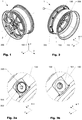
- Fig. 1 and 2 show a first embodiment of a wheel 1 according to the present invention.
- the wheel 1 comprises a wheel center 200 with a hub region 2, as well as a rim 100.
- the wheel center 200 of the embodiment shown is a spoke structure essentially made from a lightweight metal alloy, whereas the rim 100 is made from a fiber reinforced plastic.
- the present invention is not limited to such types of wheels.
- the rim 100 and the wheel center 200 are mechanically interconnected by multiple fastening means 300, which are countersunk screws.
- the fastening means 300 is partially arranged in a bushing 500 which will be shown and explained in more detail below.
- the rim 100 comprises an opening 150 that protrudes the rim 100 and extends from the inner side 110 to the outer side 130 of the rim.
- the opening 150 of the embodiment shown further comprises a recess 151 to receive a flange 550 of the bushing 500, as will be shown in more detail below.
- the recess 151 is curved and has a spherical curvature corresponding to the shape of the flange 550 of the bushing 500, as will be explained in more detail below.
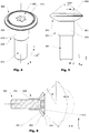
- Figs. 4 to 6 show an embodiment of an assembly comprising a fastening means 300 and a bushing 500.
- the embodiment of a bushing 500 shown comprises a flange 550 that has a first outer face 551 which is arranged for load transfer to the rim (not shown).
- the first outer face 551 of the embodiment of a bushing 500 shown has a convex shape, in particular it has a spherical curvature with a specified radius R, as illustrated in Fig. 6 and also indicated in Fig. 7 .
- the embodiment of a bushing 500 shown comprises a second outer face 555 which in a mounted state is directed away from the outer side 130 of the rim 100, as shown e.g. in Fig. 3a and subsequent Fig.
- This second outer face 555 has a conical shape having a second inner chamfer angle beta, which helps to prevent interlocking between a tire (not shown) and the fastening means 300 during mounting or dismounting of a tire.
- the embodiment of a fastening means 300 shown is a countersunk type of screw having a head 310 with a first inner chamfer angle alpha that the embodiment shown is about 90° (degrees of arc).
- the head 310 of the fastening means 300 is arranged in a bearing recess 560 (shown in Fig. 7 ) of the bushing 500, which corresponds to the inner first inner chamfer angle alpha of the fastening means' head 310.
- the variation of an embodiment of a bushing 500 shown in Figs. 4 et sqq. comprises a cylindrical sleeve portion 510 that protrudes from the flange 550 and which in a mounted state surrounds the shaft of the fastening means 300.
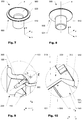
- Figs. 9 and 10 schematically show a connecting region between the rim 100 and the wheel center 200 of an embodiment of a wheel 1 according to the present invention.
- the wheel 1 shown comprises a fastening means 300 embodied as a countersunk screw and which penetrates the rim 100 via an opening 150 that extends from the inner side 110 of the rim 100 to the outer side 130 of the rim 100 and which fastening means 300 is screwed in a bore arranged in the wheel center 200.
- a bushing 500 is arranged coaxially with the fastening means 300 and thereby surrounds the fastening means 300.
- the flange 550 further comprises a first outerface 551 that has a spherical curvature as explained in more detail above.
- the first outer face 551 is arranged in a recess 151 (also shown in Fig. 3b ) of the opening 150 which has curvature that at essentially corresponds to the curvature of the first outer face 551.
- the head 310 of the fastening means 300 is arranged in a bearing recess 560 in a flange 550 of the bushing 500.
- the sleeve portion 510 of the bushing 500 is arranged in the opening 150 and protrudes into the bore arranged in the wheel center 200. Hence bending moments, respectively shear stress in the fastening means 300 can be significantly reduced.
- an intermediate layer 5 is arranged between the wheel center 200 and the inner side 110 of the rim 100 in order to optimize load transfer as well as to prevent corrosion effects.
- the contact angle between first outer face 551 and the rim 100 varies, depending on the distance from the central axis a of the flange 550.
- such an arrangement acts similar to a ball joint by compensating for angular misalignments between fastening element 300 when mechanically interconnected with the wheel center 200 and the opening 150 arranged at the rim 100.
- load transfer between the head 310 of the fastening element 300, respectively the flange 550 of the bushing 500, and the rim 100 can be optimized, leading to less stress concentration.
- interlaminar stress in the rim 100 can be reduced, which else may cause delamination in the region adjacent to the opening 150.
Claims (17)
- Rad (1), umfassend:a. eine Felge (100), die zumindest teilweise aus einem faserverstärkten Kunststoff hergestellt ist; wobei die Felge (100) eine Innenseite (110), die zum Nabenbereich (2) des Rads (1) hin gerichtet ist, und eine Außenseite (130) aufweist, die zentrifugal vom Nabenbereich (2) des Rads (1) weg gerichtet ist; undb. eine Radmitte (200), die mit der Innenseite (110) der Felge (100) mithilfe von zumindest einem Befestigungsmittel (300) verbunden ist; wobei das zumindest eine Befestigungsmittel (300) die Felge (100) durch zumindest eine Öffnung (150) durchdringt, die von der Innenseite (110) der Felge (100) zur Außenseite (130) der Felge (100) verläuft; wobei die Öffnung (150) eine Aussparung (151) umfasst, die an der Außenseite (130) der Felge (100) angeordnet ist; undc. zumindest eine Buchse (500), die koaxial mit dem zumindest einen Befestigungsmittel (300) angeordnet ist und das zumindest eine Befestigungsmittel (300) zumindest teilweise umgibt; wobei die Buchse (500) einen Flansch (550) umfasst, der zur Ausrichtung an einem Kopf (310) des zumindest einen Befestigungsmittels (300) angeordnet ist; dadurch gekennzeichnet, dass der Flansch (550) eine erste Außenseitenfläche (551) aufweist, die zumindest teilweise konvex ist und zur Ausrichtung (in einem montierten Zustand) an der Aussparung (151) angeordnet ist, welche an der Außenseite (130) der Felge (100) angeordnet ist.
- Rad (1) nach Anspruch 1, wobei die erste Außenseitenfläche (551) gekrümmt ist.
- Rad (1) nach einem der vorhergehenden Ansprüche, wobei die erste Außenseitenfläche (551) eine sphärische Krümmung aufweist.
- Rad (1) nach Anspruch 3, wobei die sphärische Krümmung einen Radius von 15 mm aufweist.
- Rad (1) nach einem der vorhergehenden Ansprüche, wobei der Flansch (550) der Buchse (500) eine Lageraussparung (560) umfasst, die zum Aufnehmen von zumindest einem Teil eines Kopfs (310) des zumindest einen Befestigungsmittels (300) angeordnet ist.
- Rad (1) nach Anspruch 5, wobei das zumindest eine Befestigungsmittel (300) einen versenkten Kopf (310) aufweist, der in einem zusammengebauten Zustand der Lageraussparung (560) entspricht.
- Rad (1) nach Anspruch 5, wobei der zumindest eine versenkte Kopf (310) einen ersten inneren Fasenwinkel (Alpha) von ungefähr 90° (Bogengrad) aufweist.
- Rad (1) nach Anspruch 5, wobei das zumindest eine Befestigungsmittel (300) einen zylindrischen Kopf aufweist, der in einem zusammengebauten Zustand mit der Lageraussparung (560) übereinstimmt.
- Rad (1) nach Anspruch 5, wobei das zumindest eine Befestigungsmittel (300) einen runden Kopf aufweist, der in einem zusammengebauten Zustand mit der Lageraussparung (560) übereinstimmt.
- Rad (1) nach einem der vorhergehenden Ansprüche, wobei der Flansch (550) eine zweite Außenseitenfläche (555) aufweist, die in einem zusammengebauten Zustand von der Außenseite (130) der Felge (100) weg gerichtet ist.
- Rad (1) nach Anspruch 10, wobei die zweite Außenseitenfläche (555) konisch geformt ist.
- Rad (1) nach Anspruch 11, wobei die zweite Außenseitenfläche (555) einen zweiten inneren Fasenwinkel (Beta) zwischen 100° und 110° (Bogengrad) aufweist.
- Rad (1) nach einem der vorhergehenden Ansprüche, wobei das Befestigungsmittel (300) und die Buchse (500) durch ein Haftmittel miteinander verbunden sind.
- Rad (1) nach einem der vorhergehenden Ansprüche, wobei eine Zwischenschicht (5) zwischen der Radmitte (200) und der Innenseite (110) der Felge (100) angeordnet ist.
- Rad (1) nach Anspruch 14, wobei die zumindest eine Zwischenschicht (5) zumindest einen tragenden Bereich/Teilabschnitt umfasst.
- Rad (1) nach einem der Ansprüche 14 und 15, wobei die Zwischenschicht (5) zumindest einen Dichtungsbereich umfasst.
- Rad (1) nach Anspruch 16, wobei der zumindest eine Dichtungsbereich umfänglich an der Zwischenschicht (5) angeordnet ist.
Applications Claiming Priority (2)
| Application Number | Priority Date | Filing Date | Title |
|---|---|---|---|
| CH4162017 | 2017-03-29 | ||
| PCT/EP2018/057367 WO2018177901A1 (en) | 2017-03-29 | 2018-03-22 | Wheel for a vehicle |
Publications (2)
| Publication Number | Publication Date |
|---|---|
| EP3600913A1 EP3600913A1 (de) | 2020-02-05 |
| EP3600913B1 true EP3600913B1 (de) | 2021-02-24 |
Family
ID=61899210
Family Applications (1)
| Application Number | Title | Priority Date | Filing Date |
|---|---|---|---|
| EP18715551.0A Active EP3600913B1 (de) | 2017-03-29 | 2018-03-22 | Rad für fahrzeug |
Country Status (2)
| Country | Link |
|---|---|
| EP (1) | EP3600913B1 (de) |
| WO (1) | WO2018177901A1 (de) |
Citations (16)
| Publication number | Priority date | Publication date | Assignee | Title |
|---|---|---|---|---|
| US1802773A (en) | 1926-10-28 | 1931-04-28 | Emil A Nelson | Wheel |
| EP0836016A2 (de) | 1996-08-21 | 1998-04-15 | Dr.Ing.h.c. F. Porsche Aktiengesellschaft | Radschraube |
| EP0921016A2 (de) | 1997-12-06 | 1999-06-09 | Dr.Ing. h.c.F. Porsche Aktiengesellschaft | Befestigungsvorrichtung für ein aus einer Radinnen- und einer Radaussenschale bestehendes Fahrzeugrad |
| US5971496A (en) | 1995-02-08 | 1999-10-26 | Mannesmann Aktiengesellschaft | Vehicle wheel having a large contact surface area |
| US6019149A (en) | 1999-09-08 | 2000-02-01 | Stringer; Raymond E. | Wheel seal and method |
| EP0976933A1 (de) | 1998-07-25 | 2000-02-02 | International Intec Trading | Verbesserungen für Mauerwerksbeschlag |
| WO2003037651A1 (en) | 2001-10-30 | 2003-05-08 | Hayes Lemmerz International, Inc. | Fabricated vehicle wheel and method for producing same |
| DE20317196U1 (de) | 2003-11-05 | 2004-01-15 | A. Agrati S.P.A., Veduggio Con Colzano | Radschraubenanordnung für PKW oder sonstige Fahrzeuge |
| WO2006097856A2 (de) | 2005-03-16 | 2006-09-21 | Dymag Racing Uk Ltd | Fahrzeugrad |
| WO2012110560A1 (de) | 2011-02-17 | 2012-08-23 | Basf Se | Fahrzeugrad |
| WO2014023598A1 (de) | 2012-08-08 | 2014-02-13 | Cool Wheels Ag | Radkonstruktion für ein automobil |
| WO2015106760A1 (de) | 2014-01-15 | 2015-07-23 | ThyssenKrupp Carbon Components GmbH | Fahrzeugrad mit einer verbindung einer radfelge mit felgenbett aus faserverbundwerkstoff und einer radscheibe |
| DE202015007418U1 (de) | 2015-10-24 | 2015-12-10 | Scc Fahrzeugtechnik Gmbh | Radschraube und/oder Felgenschloss |
| WO2016037611A1 (de) | 2014-09-09 | 2016-03-17 | ThyssenKrupp Carbon Components GmbH | Fahrzeugrad mit einer radfelge und einer radscheibe |
| WO2016066161A1 (de) | 2014-10-27 | 2016-05-06 | ThyssenKrupp Carbon Components GmbH | Fahrzeugrad mit einer verbindung zwischen einer radfelge und einer radscheibe und verfahren zu dessen herstellung |
| WO2016066769A1 (en) | 2014-10-31 | 2016-05-06 | Mubea Carbo Tech Gmbh | Wheel for a vehicle |
-
2018
- 2018-03-22 WO PCT/EP2018/057367 patent/WO2018177901A1/en unknown
- 2018-03-22 EP EP18715551.0A patent/EP3600913B1/de active Active
Patent Citations (17)
| Publication number | Priority date | Publication date | Assignee | Title |
|---|---|---|---|---|
| US1802773A (en) | 1926-10-28 | 1931-04-28 | Emil A Nelson | Wheel |
| US5971496A (en) | 1995-02-08 | 1999-10-26 | Mannesmann Aktiengesellschaft | Vehicle wheel having a large contact surface area |
| EP0836016A2 (de) | 1996-08-21 | 1998-04-15 | Dr.Ing.h.c. F. Porsche Aktiengesellschaft | Radschraube |
| EP0921016A2 (de) | 1997-12-06 | 1999-06-09 | Dr.Ing. h.c.F. Porsche Aktiengesellschaft | Befestigungsvorrichtung für ein aus einer Radinnen- und einer Radaussenschale bestehendes Fahrzeugrad |
| EP0976933A1 (de) | 1998-07-25 | 2000-02-02 | International Intec Trading | Verbesserungen für Mauerwerksbeschlag |
| US6019149A (en) | 1999-09-08 | 2000-02-01 | Stringer; Raymond E. | Wheel seal and method |
| WO2003037651A1 (en) | 2001-10-30 | 2003-05-08 | Hayes Lemmerz International, Inc. | Fabricated vehicle wheel and method for producing same |
| DE20317196U1 (de) | 2003-11-05 | 2004-01-15 | A. Agrati S.P.A., Veduggio Con Colzano | Radschraubenanordnung für PKW oder sonstige Fahrzeuge |
| WO2006097856A2 (de) | 2005-03-16 | 2006-09-21 | Dymag Racing Uk Ltd | Fahrzeugrad |
| WO2012110560A1 (de) | 2011-02-17 | 2012-08-23 | Basf Se | Fahrzeugrad |
| WO2014023598A1 (de) | 2012-08-08 | 2014-02-13 | Cool Wheels Ag | Radkonstruktion für ein automobil |
| WO2015106760A1 (de) | 2014-01-15 | 2015-07-23 | ThyssenKrupp Carbon Components GmbH | Fahrzeugrad mit einer verbindung einer radfelge mit felgenbett aus faserverbundwerkstoff und einer radscheibe |
| WO2016037611A1 (de) | 2014-09-09 | 2016-03-17 | ThyssenKrupp Carbon Components GmbH | Fahrzeugrad mit einer radfelge und einer radscheibe |
| WO2016066161A1 (de) | 2014-10-27 | 2016-05-06 | ThyssenKrupp Carbon Components GmbH | Fahrzeugrad mit einer verbindung zwischen einer radfelge und einer radscheibe und verfahren zu dessen herstellung |
| WO2016066162A1 (de) | 2014-10-27 | 2016-05-06 | ThyssenKrupp Carbon Components GmbH | Verfahren zur herstellung eines fahrzeugrads mit einer verbindung zwischen einer radfelge und einer radscheibe |
| WO2016066769A1 (en) | 2014-10-31 | 2016-05-06 | Mubea Carbo Tech Gmbh | Wheel for a vehicle |
| DE202015007418U1 (de) | 2015-10-24 | 2015-12-10 | Scc Fahrzeugtechnik Gmbh | Radschraube und/oder Felgenschloss |
Non-Patent Citations (5)
| Title |
|---|
| "DIN 74361-2 Scheibenräder für Kraftwagen und Anhängefahrzeuge - Tell 2. Befestigungselemente für Bolzenzentrierung", DIN DEUTSCHES INSTITUT FUR NORMUNG E V., 30 June 2008 (2008-06-30), XP055881344 |
| "Meyers Neues Lexikon Band 5", 1964, VEB BIBLIOGRAPHISCHES INSTITUT, Leipzig, article "Konvex", pages: 34, XP055881318 |
| ANONYMOUS: "konvex (Mathematik)", WISSEN.DE, 1 November 2021 (2021-11-01), XP055881332, [retrieved on 20220119] |
| ANONYMOUS: "konvex (Physik) ", WISSEN.DE, 1 November 2021 (2021-11-01), XP055881260, [retrieved on 20220119] |
| ANONYMOUS: "Konvexe und konkave Fläche ", DEWIKI LEXIKON, 1 November 2021 (2021-11-01), XP055881329, [retrieved on 20220119] |
Also Published As
| Publication number | Publication date |
|---|---|
| EP3600913A1 (de) | 2020-02-05 |
| WO2018177901A1 (en) | 2018-10-04 |
Similar Documents
| Publication | Publication Date | Title |
|---|---|---|
| CN102239337B (zh) | 轴承单元 | |
| US8287052B2 (en) | Wheel hub having improved stress distribution | |
| US9090289B2 (en) | Motor vehicle body with stiffening struts | |
| JP4884363B2 (ja) | 均一なトルク伝達分配を適切に促進するブレーキローター取り付けアセンブリ | |
| EP2726301B1 (de) | Befestigungsanordnung für zusammengesetzte räder | |
| US10569599B2 (en) | Vehicle wheel comprising a wheel rim and a wheel disc | |
| US20070231140A1 (en) | Rotary wing aircraft rod end and method of making a helicopter vehicle rod end with a precocked orientation | |
| US7192097B2 (en) | Vehicle wheel | |
| CN100447406C (zh) | 转子叶片连接 | |
| US11203227B2 (en) | Wheel for a vehicle | |
| JP3801647B2 (ja) | ヘリコプターロータの複合カフ構造体 | |
| US20070090685A1 (en) | Wheel for motorcycle and production method thereof | |
| US8992092B2 (en) | Flanged bearing ring for the hub of a motor vehicle wheel | |
| EP3600913B1 (de) | Rad für fahrzeug | |
| US9004612B2 (en) | Connection of a flanged ring of a hub bearing unit to a motor vehicle wheel or suspension standard of a motor vehicle | |
| US7862128B2 (en) | Vehicle wheel spoke connection | |
| EP3888934A1 (de) | Aus faserverstärktem material hergestelltes rad und verfahren zur herstellung solch eines rads | |
| CN112867607B (zh) | 车轮 | |
| WO2014162777A1 (ja) | ディスクホイール | |
| WO2015106990A1 (en) | Composite steering knuckle | |
| EP3781415B1 (de) | Rad | |
| US11485168B2 (en) | Wheel of a vehicle | |
| CN112896290A (zh) | 齿条齿轮机构、转向机构及转向系统 | |
| US20200353775A1 (en) | Vehicle wheel arrangement and method for producing a vehicle wheel arrangement | |
| EP3712452B1 (de) | Aufhängungsanordnung für ein kraftfahrzeug mit einer radnabe-wälzlagereinheit befestigt an einem achsschenkel der aufhängung |
Legal Events
| Date | Code | Title | Description |
|---|---|---|---|
| STAA | Information on the status of an ep patent application or granted ep patent |
Free format text: STATUS: UNKNOWN |
|
| STAA | Information on the status of an ep patent application or granted ep patent |
Free format text: STATUS: THE INTERNATIONAL PUBLICATION HAS BEEN MADE |
|
| PUAI | Public reference made under article 153(3) epc to a published international application that has entered the european phase |
Free format text: ORIGINAL CODE: 0009012 |
|
| STAA | Information on the status of an ep patent application or granted ep patent |
Free format text: STATUS: REQUEST FOR EXAMINATION WAS MADE |
|
| 17P | Request for examination filed |
Effective date: 20191023 |
|
| AK | Designated contracting states |
Kind code of ref document: A1 Designated state(s): AL AT BE BG CH CY CZ DE DK EE ES FI FR GB GR HR HU IE IS IT LI LT LU LV MC MK MT NL NO PL PT RO RS SE SI SK SM TR |
|
| AX | Request for extension of the european patent |
Extension state: BA ME |
|
| DAV | Request for validation of the european patent (deleted) | ||
| DAX | Request for extension of the european patent (deleted) | ||
| GRAP | Despatch of communication of intention to grant a patent |
Free format text: ORIGINAL CODE: EPIDOSNIGR1 |
|
| STAA | Information on the status of an ep patent application or granted ep patent |
Free format text: STATUS: GRANT OF PATENT IS INTENDED |
|
| INTG | Intention to grant announced |
Effective date: 20200930 |
|
| GRAS | Grant fee paid |
Free format text: ORIGINAL CODE: EPIDOSNIGR3 |
|
| GRAA | (expected) grant |
Free format text: ORIGINAL CODE: 0009210 |
|
| STAA | Information on the status of an ep patent application or granted ep patent |
Free format text: STATUS: THE PATENT HAS BEEN GRANTED |
|
| AK | Designated contracting states |
Kind code of ref document: B1 Designated state(s): AL AT BE BG CH CY CZ DE DK EE ES FI FR GB GR HR HU IE IS IT LI LT LU LV MC MK MT NL NO PL PT RO RS SE SI SK SM TR |
|
| REG | Reference to a national code |
Ref country code: CH Ref legal event code: EP |
|
| REG | Reference to a national code |
Ref country code: AT Ref legal event code: REF Ref document number: 1363974 Country of ref document: AT Kind code of ref document: T Effective date: 20210315 |
|
| REG | Reference to a national code |
Ref country code: IE Ref legal event code: FG4D |
|
| REG | Reference to a national code |
Ref country code: DE Ref legal event code: R096 Ref document number: 602018013041 Country of ref document: DE |
|
| REG | Reference to a national code |
Ref country code: LT Ref legal event code: MG9D |
|
| REG | Reference to a national code |
Ref country code: NL Ref legal event code: MP Effective date: 20210224 |
|
| PG25 | Lapsed in a contracting state [announced via postgrant information from national office to epo] |
Ref country code: LT Free format text: LAPSE BECAUSE OF FAILURE TO SUBMIT A TRANSLATION OF THE DESCRIPTION OR TO PAY THE FEE WITHIN THE PRESCRIBED TIME-LIMIT Effective date: 20210224 Ref country code: PT Free format text: LAPSE BECAUSE OF FAILURE TO SUBMIT A TRANSLATION OF THE DESCRIPTION OR TO PAY THE FEE WITHIN THE PRESCRIBED TIME-LIMIT Effective date: 20210624 Ref country code: NO Free format text: LAPSE BECAUSE OF FAILURE TO SUBMIT A TRANSLATION OF THE DESCRIPTION OR TO PAY THE FEE WITHIN THE PRESCRIBED TIME-LIMIT Effective date: 20210524 Ref country code: FI Free format text: LAPSE BECAUSE OF FAILURE TO SUBMIT A TRANSLATION OF THE DESCRIPTION OR TO PAY THE FEE WITHIN THE PRESCRIBED TIME-LIMIT Effective date: 20210224 Ref country code: HR Free format text: LAPSE BECAUSE OF FAILURE TO SUBMIT A TRANSLATION OF THE DESCRIPTION OR TO PAY THE FEE WITHIN THE PRESCRIBED TIME-LIMIT Effective date: 20210224 Ref country code: GR Free format text: LAPSE BECAUSE OF FAILURE TO SUBMIT A TRANSLATION OF THE DESCRIPTION OR TO PAY THE FEE WITHIN THE PRESCRIBED TIME-LIMIT Effective date: 20210525 Ref country code: BG Free format text: LAPSE BECAUSE OF FAILURE TO SUBMIT A TRANSLATION OF THE DESCRIPTION OR TO PAY THE FEE WITHIN THE PRESCRIBED TIME-LIMIT Effective date: 20210524 |
|
| PG25 | Lapsed in a contracting state [announced via postgrant information from national office to epo] |
Ref country code: SE Free format text: LAPSE BECAUSE OF FAILURE TO SUBMIT A TRANSLATION OF THE DESCRIPTION OR TO PAY THE FEE WITHIN THE PRESCRIBED TIME-LIMIT Effective date: 20210224 Ref country code: NL Free format text: LAPSE BECAUSE OF FAILURE TO SUBMIT A TRANSLATION OF THE DESCRIPTION OR TO PAY THE FEE WITHIN THE PRESCRIBED TIME-LIMIT Effective date: 20210224 Ref country code: PL Free format text: LAPSE BECAUSE OF FAILURE TO SUBMIT A TRANSLATION OF THE DESCRIPTION OR TO PAY THE FEE WITHIN THE PRESCRIBED TIME-LIMIT Effective date: 20210224 Ref country code: LV Free format text: LAPSE BECAUSE OF FAILURE TO SUBMIT A TRANSLATION OF THE DESCRIPTION OR TO PAY THE FEE WITHIN THE PRESCRIBED TIME-LIMIT Effective date: 20210224 Ref country code: RS Free format text: LAPSE BECAUSE OF FAILURE TO SUBMIT A TRANSLATION OF THE DESCRIPTION OR TO PAY THE FEE WITHIN THE PRESCRIBED TIME-LIMIT Effective date: 20210224 |
|
| PG25 | Lapsed in a contracting state [announced via postgrant information from national office to epo] |
Ref country code: IS Free format text: LAPSE BECAUSE OF FAILURE TO SUBMIT A TRANSLATION OF THE DESCRIPTION OR TO PAY THE FEE WITHIN THE PRESCRIBED TIME-LIMIT Effective date: 20210624 |
|
| PG25 | Lapsed in a contracting state [announced via postgrant information from national office to epo] |
Ref country code: CZ Free format text: LAPSE BECAUSE OF FAILURE TO SUBMIT A TRANSLATION OF THE DESCRIPTION OR TO PAY THE FEE WITHIN THE PRESCRIBED TIME-LIMIT Effective date: 20210224 Ref country code: EE Free format text: LAPSE BECAUSE OF FAILURE TO SUBMIT A TRANSLATION OF THE DESCRIPTION OR TO PAY THE FEE WITHIN THE PRESCRIBED TIME-LIMIT Effective date: 20210224 Ref country code: SM Free format text: LAPSE BECAUSE OF FAILURE TO SUBMIT A TRANSLATION OF THE DESCRIPTION OR TO PAY THE FEE WITHIN THE PRESCRIBED TIME-LIMIT Effective date: 20210224 |
|
| REG | Reference to a national code |
Ref country code: CH Ref legal event code: PL |
|
| REG | Reference to a national code |
Ref country code: AT Ref legal event code: UEP Ref document number: 1363974 Country of ref document: AT Kind code of ref document: T Effective date: 20210224 |
|
| REG | Reference to a national code |
Ref country code: DE Ref legal event code: R026 Ref document number: 602018013041 Country of ref document: DE |
|
| PLBI | Opposition filed |
Free format text: ORIGINAL CODE: 0009260 |
|
| PG25 | Lapsed in a contracting state [announced via postgrant information from national office to epo] |
Ref country code: MC Free format text: LAPSE BECAUSE OF FAILURE TO SUBMIT A TRANSLATION OF THE DESCRIPTION OR TO PAY THE FEE WITHIN THE PRESCRIBED TIME-LIMIT Effective date: 20210224 Ref country code: RO Free format text: LAPSE BECAUSE OF FAILURE TO SUBMIT A TRANSLATION OF THE DESCRIPTION OR TO PAY THE FEE WITHIN THE PRESCRIBED TIME-LIMIT Effective date: 20210224 Ref country code: SK Free format text: LAPSE BECAUSE OF FAILURE TO SUBMIT A TRANSLATION OF THE DESCRIPTION OR TO PAY THE FEE WITHIN THE PRESCRIBED TIME-LIMIT Effective date: 20210224 Ref country code: DK Free format text: LAPSE BECAUSE OF FAILURE TO SUBMIT A TRANSLATION OF THE DESCRIPTION OR TO PAY THE FEE WITHIN THE PRESCRIBED TIME-LIMIT Effective date: 20210224 |
|
| PLAX | Notice of opposition and request to file observation + time limit sent |
Free format text: ORIGINAL CODE: EPIDOSNOBS2 |
|
| REG | Reference to a national code |
Ref country code: BE Ref legal event code: MM Effective date: 20210331 |
|
| 26 | Opposition filed |
Opponent name: ACTION COMPOSITES HIGHTECH GMBH Effective date: 20211123 |
|
| PG25 | Lapsed in a contracting state [announced via postgrant information from national office to epo] |
Ref country code: IE Free format text: LAPSE BECAUSE OF NON-PAYMENT OF DUE FEES Effective date: 20210322 Ref country code: LI Free format text: LAPSE BECAUSE OF NON-PAYMENT OF DUE FEES Effective date: 20210331 Ref country code: LU Free format text: LAPSE BECAUSE OF NON-PAYMENT OF DUE FEES Effective date: 20210322 Ref country code: AL Free format text: LAPSE BECAUSE OF FAILURE TO SUBMIT A TRANSLATION OF THE DESCRIPTION OR TO PAY THE FEE WITHIN THE PRESCRIBED TIME-LIMIT Effective date: 20210224 Ref country code: CH Free format text: LAPSE BECAUSE OF NON-PAYMENT OF DUE FEES Effective date: 20210331 Ref country code: ES Free format text: LAPSE BECAUSE OF FAILURE TO SUBMIT A TRANSLATION OF THE DESCRIPTION OR TO PAY THE FEE WITHIN THE PRESCRIBED TIME-LIMIT Effective date: 20210224 |
|
| PG25 | Lapsed in a contracting state [announced via postgrant information from national office to epo] |
Ref country code: SI Free format text: LAPSE BECAUSE OF FAILURE TO SUBMIT A TRANSLATION OF THE DESCRIPTION OR TO PAY THE FEE WITHIN THE PRESCRIBED TIME-LIMIT Effective date: 20210224 |
|
| PLBB | Reply of patent proprietor to notice(s) of opposition received |
Free format text: ORIGINAL CODE: EPIDOSNOBS3 |
|
| PG25 | Lapsed in a contracting state [announced via postgrant information from national office to epo] |
Ref country code: IS Free format text: LAPSE BECAUSE OF FAILURE TO SUBMIT A TRANSLATION OF THE DESCRIPTION OR TO PAY THE FEE WITHIN THE PRESCRIBED TIME-LIMIT Effective date: 20210624 |
|
| PG25 | Lapsed in a contracting state [announced via postgrant information from national office to epo] |
Ref country code: BE Free format text: LAPSE BECAUSE OF NON-PAYMENT OF DUE FEES Effective date: 20210331 |
|
| PGFP | Annual fee paid to national office [announced via postgrant information from national office to epo] |
Ref country code: FR Payment date: 20230327 Year of fee payment: 6 Ref country code: AT Payment date: 20230322 Year of fee payment: 6 |
|
| PGFP | Annual fee paid to national office [announced via postgrant information from national office to epo] |
Ref country code: IT Payment date: 20230328 Year of fee payment: 6 Ref country code: GB Payment date: 20230322 Year of fee payment: 6 Ref country code: DE Payment date: 20230321 Year of fee payment: 6 |
|
| P01 | Opt-out of the competence of the unified patent court (upc) registered |
Effective date: 20230515 |
|
| PG25 | Lapsed in a contracting state [announced via postgrant information from national office to epo] |
Ref country code: CY Free format text: LAPSE BECAUSE OF FAILURE TO SUBMIT A TRANSLATION OF THE DESCRIPTION OR TO PAY THE FEE WITHIN THE PRESCRIBED TIME-LIMIT Effective date: 20210224 |
|
| PG25 | Lapsed in a contracting state [announced via postgrant information from national office to epo] |
Ref country code: HU Free format text: LAPSE BECAUSE OF FAILURE TO SUBMIT A TRANSLATION OF THE DESCRIPTION OR TO PAY THE FEE WITHIN THE PRESCRIBED TIME-LIMIT; INVALID AB INITIO Effective date: 20180322 |
|
| PLAB | Opposition data, opponent's data or that of the opponent's representative modified |
Free format text: ORIGINAL CODE: 0009299OPPO |
|
| R26 | Opposition filed (corrected) |
Opponent name: ACTION COMPOSITES HIGHTECH GMBH (I.L.) Effective date: 20211123 |
|
| PLBP | Opposition withdrawn |
Free format text: ORIGINAL CODE: 0009264 |
|
| PGFP | Annual fee paid to national office [announced via postgrant information from national office to epo] |
Ref country code: AT Payment date: 20240321 Year of fee payment: 7 |
|
| PG25 | Lapsed in a contracting state [announced via postgrant information from national office to epo] |
Ref country code: MK Free format text: LAPSE BECAUSE OF FAILURE TO SUBMIT A TRANSLATION OF THE DESCRIPTION OR TO PAY THE FEE WITHIN THE PRESCRIBED TIME-LIMIT Effective date: 20210224 |
|
| PGFP | Annual fee paid to national office [announced via postgrant information from national office to epo] |
Ref country code: DE Payment date: 20240320 Year of fee payment: 7 Ref country code: GB Payment date: 20240320 Year of fee payment: 7 |