EP3600830B1 - Vorrichtung und verfahren zum aufbringen von schutzfolien - Google Patents
Vorrichtung und verfahren zum aufbringen von schutzfolien Download PDFInfo
- Publication number
- EP3600830B1 EP3600830B1 EP18715472.9A EP18715472A EP3600830B1 EP 3600830 B1 EP3600830 B1 EP 3600830B1 EP 18715472 A EP18715472 A EP 18715472A EP 3600830 B1 EP3600830 B1 EP 3600830B1
- Authority
- EP
- European Patent Office
- Prior art keywords
- film
- frame
- adhesive film
- target surface
- optionally
- Prior art date
- Legal status (The legal status is an assumption and is not a legal conclusion. Google has not performed a legal analysis and makes no representation as to the accuracy of the status listed.)
- Active
Links
- 230000001681 protective effect Effects 0.000 title description 54
- 238000000034 method Methods 0.000 title description 13
- 239000002313 adhesive film Substances 0.000 claims description 73
- 238000000926 separation method Methods 0.000 claims description 8
- 239000000853 adhesive Substances 0.000 claims description 6
- 230000001070 adhesive effect Effects 0.000 claims description 6
- 238000007373 indentation Methods 0.000 claims description 6
- 210000000707 wrist Anatomy 0.000 claims description 2
- 239000010410 layer Substances 0.000 description 29
- 238000005516 engineering process Methods 0.000 description 18
- 239000012790 adhesive layer Substances 0.000 description 7
- 230000015572 biosynthetic process Effects 0.000 description 7
- 239000000463 material Substances 0.000 description 6
- 230000001012 protector Effects 0.000 description 5
- 238000004140 cleaning Methods 0.000 description 3
- 239000000428 dust Substances 0.000 description 3
- 230000008878 coupling Effects 0.000 description 2
- 238000010168 coupling process Methods 0.000 description 2
- 238000005859 coupling reaction Methods 0.000 description 2
- 230000008021 deposition Effects 0.000 description 2
- 239000004744 fabric Substances 0.000 description 2
- 230000013011 mating Effects 0.000 description 2
- 230000007246 mechanism Effects 0.000 description 2
- 238000002360 preparation method Methods 0.000 description 2
- 239000007787 solid Substances 0.000 description 2
- 239000000243 solution Substances 0.000 description 2
- 238000003466 welding Methods 0.000 description 2
- 238000004026 adhesive bonding Methods 0.000 description 1
- 230000001413 cellular effect Effects 0.000 description 1
- 150000001875 compounds Chemical class 0.000 description 1
- 238000005520 cutting process Methods 0.000 description 1
- 230000006378 damage Effects 0.000 description 1
- 230000007613 environmental effect Effects 0.000 description 1
- 239000011888 foil Substances 0.000 description 1
- 238000002347 injection Methods 0.000 description 1
- 239000007924 injection Substances 0.000 description 1
- 238000004519 manufacturing process Methods 0.000 description 1
- 239000002184 metal Substances 0.000 description 1
- 239000002245 particle Substances 0.000 description 1
- 239000004033 plastic Substances 0.000 description 1
- 229920001296 polysiloxane Polymers 0.000 description 1
- 238000004064 recycling Methods 0.000 description 1
- 230000000284 resting effect Effects 0.000 description 1
- 238000007665 sagging Methods 0.000 description 1
- 230000003068 static effect Effects 0.000 description 1
- 239000000126 substance Substances 0.000 description 1
- 239000002699 waste material Substances 0.000 description 1
Images


Classifications
-
- B—PERFORMING OPERATIONS; TRANSPORTING
- B29—WORKING OF PLASTICS; WORKING OF SUBSTANCES IN A PLASTIC STATE IN GENERAL
- B29C—SHAPING OR JOINING OF PLASTICS; SHAPING OF MATERIAL IN A PLASTIC STATE, NOT OTHERWISE PROVIDED FOR; AFTER-TREATMENT OF THE SHAPED PRODUCTS, e.g. REPAIRING
- B29C63/00—Lining or sheathing, i.e. applying preformed layers or sheathings of plastics; Apparatus therefor
- B29C63/02—Lining or sheathing, i.e. applying preformed layers or sheathings of plastics; Apparatus therefor using sheet or web-like material
-
- G—PHYSICS
- G06—COMPUTING; CALCULATING OR COUNTING
- G06F—ELECTRIC DIGITAL DATA PROCESSING
- G06F1/00—Details not covered by groups G06F3/00 - G06F13/00 and G06F21/00
- G06F1/16—Constructional details or arrangements
- G06F1/1601—Constructional details related to the housing of computer displays, e.g. of CRT monitors, of flat displays
- G06F1/1607—Arrangements to support accessories mechanically attached to the display housing
- G06F1/1609—Arrangements to support accessories mechanically attached to the display housing to support filters or lenses
-
- G—PHYSICS
- G06—COMPUTING; CALCULATING OR COUNTING
- G06F—ELECTRIC DIGITAL DATA PROCESSING
- G06F1/00—Details not covered by groups G06F3/00 - G06F13/00 and G06F21/00
- G06F1/16—Constructional details or arrangements
- G06F1/1613—Constructional details or arrangements for portable computers
- G06F1/1628—Carrying enclosures containing additional elements, e.g. case for a laptop and a printer
-
- B—PERFORMING OPERATIONS; TRANSPORTING
- B29—WORKING OF PLASTICS; WORKING OF SUBSTANCES IN A PLASTIC STATE IN GENERAL
- B29C—SHAPING OR JOINING OF PLASTICS; SHAPING OF MATERIAL IN A PLASTIC STATE, NOT OTHERWISE PROVIDED FOR; AFTER-TREATMENT OF THE SHAPED PRODUCTS, e.g. REPAIRING
- B29C63/00—Lining or sheathing, i.e. applying preformed layers or sheathings of plastics; Apparatus therefor
- B29C63/0004—Component parts, details or accessories; Auxiliary operations
- B29C2063/0008—Registering, centering the lining material on the substrate
-
- B—PERFORMING OPERATIONS; TRANSPORTING
- B29—WORKING OF PLASTICS; WORKING OF SUBSTANCES IN A PLASTIC STATE IN GENERAL
- B29C—SHAPING OR JOINING OF PLASTICS; SHAPING OF MATERIAL IN A PLASTIC STATE, NOT OTHERWISE PROVIDED FOR; AFTER-TREATMENT OF THE SHAPED PRODUCTS, e.g. REPAIRING
- B29C63/00—Lining or sheathing, i.e. applying preformed layers or sheathings of plastics; Apparatus therefor
- B29C63/02—Lining or sheathing, i.e. applying preformed layers or sheathings of plastics; Apparatus therefor using sheet or web-like material
- B29C2063/027—Lining or sheathing, i.e. applying preformed layers or sheathings of plastics; Apparatus therefor using sheet or web-like material applied by a squeegee
-
- B—PERFORMING OPERATIONS; TRANSPORTING
- B29—WORKING OF PLASTICS; WORKING OF SUBSTANCES IN A PLASTIC STATE IN GENERAL
- B29C—SHAPING OR JOINING OF PLASTICS; SHAPING OF MATERIAL IN A PLASTIC STATE, NOT OTHERWISE PROVIDED FOR; AFTER-TREATMENT OF THE SHAPED PRODUCTS, e.g. REPAIRING
- B29C63/00—Lining or sheathing, i.e. applying preformed layers or sheathings of plastics; Apparatus therefor
- B29C63/0056—Provisional sheathings
-
- B—PERFORMING OPERATIONS; TRANSPORTING
- B29—WORKING OF PLASTICS; WORKING OF SUBSTANCES IN A PLASTIC STATE IN GENERAL
- B29C—SHAPING OR JOINING OF PLASTICS; SHAPING OF MATERIAL IN A PLASTIC STATE, NOT OTHERWISE PROVIDED FOR; AFTER-TREATMENT OF THE SHAPED PRODUCTS, e.g. REPAIRING
- B29C63/00—Lining or sheathing, i.e. applying preformed layers or sheathings of plastics; Apparatus therefor
- B29C63/0095—Lining or sheathing, i.e. applying preformed layers or sheathings of plastics; Apparatus therefor using a provisional carrier
Definitions
- the present technology is directed to effective application of protective films on surfaces of various apparatuses.
- Protective films are commonly applied to maintain the condition and appearance of underlying surfaces. Such films are typically configured to provide some form of self-adhesion with the surface that they seek to protect. Some films are configured to be readily removable with little residue. Easy removability is typically desirable were the protective film is configured as a replaceable wear item. Compared to the object they are intended to protect, such films are typically inexpensive and designed to be replaced when their appearance is deteriorated. Such films are particularly common to protect the surface of displays or other exterior surfaces of mobile or personal computer devices, for example cellular phones and tablet computers. Proper alignment and a film application that is free from bubbles and inclusions are particularly important to maintain visibility and homogenous appearance of laminated device displays.
- United States Patent Application Publication No. US 2016/0009024 to Mason describes an applicator for applying protective films to electronic device displays.
- the applicator includes a base, a screen protector, and a squeegee.
- the base includes a pocket for receiving an electronic device.
- the screen protector is affixed to the base to overlie the electronic device.
- the screen protector includes three layers including a protective film, cap sheet and back liner.
- the back liner includes one or two tags which extend beyond the edge of the protective film to allow the user to manually peel the back liner from the protective film.
- the squeegee is provided for removing the back liner and for simultaneously affixing the protective film to an electronic device.
- Mason's applicator is bulky, complicated, and difficult to operate.
- Cida Patent No. CN 203345234 to Wang discloses a film pasting device which comprises a base, a roller wheel seat and a stripping roller.
- the base is provided with a device positioning cavity, a sliding channel, a front positioning groove and a positioning pillar.
- the roller wheel seat is composed of a roller wheel shell, a stripping-assisting part and a roller.
- a roller shaft seat, a clamping groove and a sliding rail are arranged on the roller wheel shell.
- a roller is arranged in the roller shaft seat.
- the stripping-assisting part is composed of an L-shaped sheet and double positioning arms. The included angle between the L-shaped sheet and the double positioning arms ranges frame 45 degrees to 60 degrees.
- European Patent Application Publication No. EP 2730992 to Hsu et al describes an application apparatus and a screen protector.
- the application apparatus is a frame-like structure with an internal hollow region for containing the screen protector that is configured to attach an adhesive film to an electronic device by sliding the application apparatus over an outer contour of the electronic device after peeling a release layer from under the adhesive film.
- the application apparatus of Hsu et al. is unreliable as it seeks to accomplish registration between the film and the electronic device while applying the adhesive film suddenly across the whole extension of the film and is prone to bubble formation.
- United States Patent Application Publication No. US 2009/0186181 to Mase discloses a multilayer protective film including a split adhesive layer configured to facilitate initial alignment and to provide surface cleaning by sacrificial peeling of the split adhesive layer in preparation for the application of a second adhesive layer intended for actual protection of electronic device screen.
- Mase's multilayer protective film requires manual film alignment and entails an elaborate application procedure while it relies on the durability of the alignment of the initially applied split adhesive layer until the application of the second adhesive layer is complete. As such it is prone to alignment errors and cumbersome in its application.
- Chinese Patent Application Publication No. CN 105314153 to Wu is an example describing a method for applying a protective film using removable adhesive stickers configured as an aid to align the film with an edge of a mobile phone in preparation for the film application. Wu's method only allows for sudden deposition of the whole film on the mobile phone surface and hence is prone to bubble formation.
- An object of the present technology is to provide a device for applying protective films.
- a device comprising a frame configured to couple removably with an apparatus in an attached configuration; and an adhesive film having a first portion removably coupled with the frame and a second portion spaced apart from the first portion.
- the adhesive film is configured to adhere to a target surface of the apparatus.
- the first portion is being held a distance away from the surface of the apparatus and the second portion registers in a predetermined manner with the target surface of the apparatus.
- the present technology provides a device for applying films to displays or other target surfaces of apparatuses such as phones, tablets, laptop and desktop computers, wrist watches, cameras, televisions, measuring instruments or other apparatuses, for example.
- the device includes a frame and a multi-layer pad including a protective adhesive film.
- the protective adhesive film is transparent.
- the pad with the adhesive film is supported and removably coupled with the frame, for example along an edge of the film.
- the frame is configured to be clamped or otherwise coupled with the apparatus. When fully coupled, the frame and the apparatus can register accurately within a certain tolerance and in turn the film can accurately register with the target surface of the apparatus.
- the adhesive film When taut, the adhesive film can be laid down beginning distal of the supported edge that is coupled with the frame while the portion of the adhesive film near the supported edge is kept slightly elevated by a predetermined distance above the target surface by the frame to facilitate the application process. After its distal edge has been attached, the adhesive film can then be pasted onto the apparatus using a suitable spatula or other aid. In some implementations, the application of the protective adhesive film can be completed and the apparatus separated from the frame after peeling a sacrificial top film from the protective adhesive film.
- the film-application device allows for reliable registration between the adhesive film and the target surface of the apparatus and can mitigate inclusion and bubble formation during film application.
- the present device and application process can provide pasted adhesive film that is free from visible imperfections.
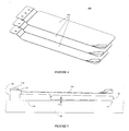
- Figure 1 shows a perspective view of an assembly of an example film-application device 100 according to the present technology with an inserted mobile phone 10.
- Figure 2 shows an exploded perspective view of the assembly of Figure 1 .
- Figure 3 shows a perspective view of the assembly of Figure 1 from below.
- the example film-application device 100 is configured for application of a protective film to a target surface 11 provided by a front face of a mobile phone 10.
- the target surface 11 includes the display and other areas of the front face but omits buttons, cameras, speakers and light sources.
- the target surface includes only the display of the mobile phone.
- the film-application device 100 includes a frame 110 with a cap 113 and a multi-layer pad 120.
- Figure 1 shows the multi-layer pad 120 resting on the mobile phone 10.
- the multi-layer pad 120 includes a tab 121, a top film 122, a bottom film 124 and a transparent protective adhesive film 123.
- the transparent protective adhesive film 123 is configured to extend across the target surface 11 and includes corresponding apertures (not illustrated) to accommodate various elements on the front face of the mobile phone 10 as noted above.
- one or more of the three films 122, 123 and 124 may be opaque, translucent, or partially or fully transparent, for example.
- the top film 122 may be transparent and have a bluish or other color hue that enhances contrast versus the target surface 11. Good contrast can aid the user in the recognition of features such as edges and apertures of the target surface 11 and the pad 120 during film application and hence facilitate the registration of the transparent protective adhesive film 123 with the target surface 11.
- the multi-layer pad 120 is shown to rest on the mobile phone 10. Features in or under the multi-layer pad 120 are not illustrated.
- Figure 2 shows the multiple films 122, 123 and 124 schematically fanned out at a corner 12.
- the multi-layer pad 120 further includes protruding tabs 1221, 1223 and 1241 (see Figures 10A and 10B ) configured to facilitate separation of the multiple films 122, 123 and 124 by peeling.
- the tabs 1221, 1223 and 1241 are formed from separate strips of suitable material adhered to respective films. The separate nature and adhesion of the tabs with the films are not indicated in Figures 10A and 10B .
- the tabs 1221 and 1223 are adhered to the top of and protrude from the top film 122, the tab 1241 is adhered to the bottom of and protrudes from the bottom film 124.
- the multi-layer pad 120 can be fabricated from a sandwiched web material that includes films 122, 123 and 124 and is die cut to fit the target surface 11. Tabs 1221, 1223 and 1241 then can be adhered after die cutting. In other examples, tabs may be formed integrally with like or other films of respective multi-layer pads. Generally, one or more of the top, bottom and/or the transparent protective adhesive films may be provided with one or more tabs in various combinations to facilitate separation.
- the frame 110 is shaped to clamp resiliently to the mobile phone 10 by grabbing onto a U-shaped portion of the circumference of the mobile phone 10 and includes indentations 1103 and an opening 1105 to accommodate buttons 13, camera components (not illustrated) or other elements protruding from the mobile phone 10.
- the frame 110 is configured so it can hold the taut pad 120 with the transparent protective adhesive film 123 slightly elevated by a certain distance above the target surface 11 near the supported edge 1201.
- the frame 110 near the supported edge 1201 is slanted in a flat manner.
- the recess and height of the slant may be configured to control a remaining amount of transparent protective adhesive film 123 that may only be applied at like distances to the target surface 11 after the mobile phone 10 and the frame 110 are separated. Further details about the film application process are described with respect to Figures 10A through 10F .
- Other example film-application devices may have edges with different or no slants.
- the transparent protective adhesive film 123 is sandwiched between the top film 122 and the bottom film 124.
- the top film 122 and the bottom film 124 are configured to protect the transparent protective adhesive film 123 from dust and scratches for example, until it is pasted onto the target surface 11 of the mobile phone 10.
- the tab 121 is formed from a separate strip of suitable material adhered to the top of the top film 124 to form a protrusion of the pad 120 and is configured to engage and reliably register the pad 120 with the frame 110 along the supported edge 1201.
- the separate nature and adhesion of the tab 121 with respect to the top film 124 are not indicated in the figures.
- the tab 121 includes three openings 1211 configured to mate with protrusions 1131 provided by a cap 113.
- the frame 110 has like openings 111 configured to mate with the protrusions 1131 of cap 113 so that the multi-layer pad 120 can be coupled accurately to the frame 110.
- the tab 121 can be formed as an integral protrusion of the top film, for example.
- the pad 120 can be securely coupled to the frame 110 via the cap 113 during manufacture or later by an end user, for example.
- a respective coupling may be established by welding or a friction fit, for example.
- respective parts may be removable or irremovable by the end user.
- Film-application devices with a removable cap can be used to secure suitable pads onto the frame by the end user.
- the pad may be coupled with the frame in other ways.
- the bottom film may be split into a portion proximate the supported edge that includes a tab secured to the frame and a distal portion that can be peeled away independently to allow exposing a portion of an adhesive side of a respective protective adhesive film and initial placement and adhesion of same on the target surface distal of the supported edge.
- protective adhesive film may be directly coupled to the frame and include a predetermined break line configured to allow separation of the protective adhesive film from the frame.
- the example film-application device 100 of Figure 1 is shown to include a single multi-layer pad 120 which allows one film application.
- Other example film-application devices may include several multi-layer pads to allow reuse of the device for multiple film applications.
- Such example film-application devices may be used to replace worn protective adhesive films previously applied to target surfaces with protective adhesive films from remaining unused multi-layer pads.
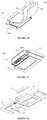
- Figure 4 illustrates an exploded view of an example pad package 400 including three multi-layer pads. Each of the pads 410 is shown schematically fanned out at respective corners.
- Such pad packages can be configured to include pads with one or more creases to allow easy folding away of unused pads during film application.
- One or more of the films of each pad further may include one or more protruding tabs (not illustrated) configured to facilitate separation of each pad.
- Such tabs may be located along one or more edges of respective films, for example distal of the frame.
- pads and pad packages may be provided to an end user separately or already affixed to a film-application device. In implementations with several multi-layer pads, the pad that is closest to the inserted apparatus is being used during film application while any extra unused pads are folded away.
- the frame 110 of the example film-application device 100 has a base 119 that is tapered at an angle 21 relative to a back surface of a properly attached mobile phone 10 to avoid rocking the assembly on a flat external support 20 such as a tabletop, for example.
- Figure 5 illustrates an example.
- the angle 21 can be chosen to form a three-point support between an edge 15 of the mobile phone 10 and the base 119 of the frame 110.
- the base 119 has a flat bottom surface and is configured to establish solid contact with the support 20 when the mobile phone 10 is attached.
- the base 119 and/or other portions of the frame 110 may optionally be provided with surfaces configured to increase friction between the frame 110 and the external support 20.
- Such surfaces may include one or more rubber, silicone or other slip-mitigating elements configured to increase adhesion to and/or friction (not illustrated) with the external support 20.
- such surfaces may include one or more adhesive strips which can be configured for single or multiple use.
- Figures 6 , 7A through 7D , 8 and 9 show a selection of further example film-application devices according to the present technology.
- Figure 6 shows an example film-application device 600 similar to the example film-application device 100 but uses a long edge to both clamp the frame 610 to an apparatus and to support a multi-layer pad 620 with a protective adhesive film.
- Figure 7A shows another example film-application device 700 with a multi-layer pad 720, and a frame 710 that includes a retractable resiliently biased arm 715 configured to clamp and register an apparatus with the frame 710.
- biasing mechanisms can include a spring-loaded arm ⁇ see example in Figures 7B through 7D , or a friction fit arm engaging a rubber or other suitable frame insert, or a releasable anti-reverse mechanism including a toothed rack configured to engage a releasable ratchet pawl, for example.
- the retractable arm can be configured to attach to apparatuses of different width.
- Figures 7B through 7D show various views of an example film-application device 7000 with a spring 7030, a spring-loaded arm 7020 and a frame 7010 and two multi-layer pads 7022 and 7024 with respective tabs.
- the film-application device 7000 is configured to attach apparatuses of different width.
- Figure 7B shows the two multi-layer pads 7022 and 7024 fanned out.
- the spring-loaded arm 7020 has a T-shaped profile and the frame 7010 includes two ridges 7017a and 7017b with correspondingly shaped openings to guide the spring-loaded arm 7020 when assembled ⁇ see bottom view of the film-application device 7000 in Figure 7C , for example.
- the frame 7010 is arranged to provide a chamber shaped to accommodate the spring 7030.
- the spring-loaded arm 7020 is slidably coupled with the frame 7010 via noted openings in the ridges 7017a/b and the spring 7030 such that the spring-loaded arm 7020 can resiliently clamp and register an apparatus (not illustrated) with the frame 7010 in the attached configuration.
- the film-application device 7000 includes a bottom plate 7040 configured to close off the bottom of the frame 7010 and enclose the spring 7030.
- the film-application device 7000 further includes a pair of inserts 7050 and 7060 best visible in Figure 7D .
- inserts 7050 and 7060 are shaped to fit certain apparatus.
- an insert can be shaped and/or include through holes, protrusions and/or indentations configured to engage with edges, indentations and/or protrusions of an apparatus, respectively.
- Inserts may be supplied to a user or be installed during assembly of the film-application device 7000, for example. As such different inserts can be supplied to fit different types of apparatuses. Correspondingly configured multi-layer pads may be supplied to a user or selected during assembly respectively, as different apparatuses may require different types, sizes or other configurations of protective films.
- the insert and the frame can include mating features, for example, features 7061 and 7062.
- Such features can include protrusions, indentations, through holes or other mating features.
- Figure 8 shows another example film-application device 800 with a frame 810 that is configured to couple resiliently with a pad-support pin 825.
- the coupling is configured to allow pivoting the pad-support pin 825 relative to the frame 810.
- the pad-support pin 825 is coupled to a multi-layer pad 820 which includes a protective adhesive film.
- the pad-support pin 825 can be coupled and decoupled repeatedly from the frame 810 facilitated by a handle 827 attached to the pad-support pin 825.
- Figure 9 shows another example film-application device 900 with a frame 910 that is configured to couple resiliently with a pad-support pin 925 and allow pivoting the pad-support pin 925 relative to the - frame 910.
- the example film-application device 900 is similar to the example film-application device 800 but additionally includes a through hole in form of a slit 911 in the frame 910.
- the slit 911 is shaped and sized to receive a multi-layer pad 920 or portion thereof and thread it through to the bottom side of the frame 910 away from the top intended to face a target surface for film application.
- the slit 911 can be used to receive and stow away a bottom film that is fixedly attached to the pad-support pin 925 after separation from the multi-layer pad 920.
- pad-support pins can be configured to provide one or more multi-layer pads. Pad-support pins may be supplied separately as replacement items and configured to allow multiple film applications using the same frame.
- a protective adhesive film is formed from a material that on its own provides sufficient adhesion with the target surface without requiring a separate substance to facilitate adhesion.
- adhesive films may be configured to leave no residue on the target surface after removal.
- a separate adhesive layer may be employed. Such adhesive layers can be configured to leave or not leave residue on the target surface after removal.
- film-application devices can comprise different materials such as plastic, metal, compound or other materials, for example.
- Film-application devices may be formed integrally or from multiple separate components. Separate components can be configured to interlock and allow repeat disassembly and assembly without destruction, or be permanently adhered by gluing, welding, vulcanizing or other means, for example. Integrally formed film-application devices or parts thereof may be injection molded, cast, machined, or otherwise fabricated.
- film application devices can be configured to permit reuse, recycling, disposal or other aspects.
- film application devices may be of small size and configured to employ and produce small amounts of waste material.
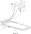
- FIGS 10A through 10F show examples of steps during film application in which bold arrows indicate directions of force application.
- the target surface 11 of the mobile phone 10 can be cleaned (not illustrated) in a suitable manner, for example by using a cloth, a cleaning solution or other method.
- the mobile phone 10 is attached to the frame 110 to establish a properly registered assembly. This can be done after or before cleaning.
- the bottom film 124 can then be peeled from the multi-layer pad 120 to access the face of the transparent protective adhesive film 123 that is configured to adhere to the target surface 11 of the mobile phone 10.
- FIG. 10A shows the assembly with a partially removed bottom film 124. After removal, the bottom film 124 can be set aside and/or disposed of. At this point, the portion of the pad 120 that remains coupled with the frame 110 includes the transparent protective adhesive film 123 and top film 122.
- the pad 120 can then be taut slightly and the transparent protective adhesive film 123 laid down onto the target surface 11 distal of the supported edge that is coupled with the frame 110.
- Tabs 1221 and 1223 can be used to conveniently hold and taut the remainder of the pad 120 including the top film 122 and the transparent protective adhesive film 123.
- Figure 10B shows the assembly at this stage of the film-application process.
- the film-application device 100 is configured to allow a portion of the adhesive film extending from the supported edge to remain slightly elevated above the target surface without further manipulation to avoid inadvertent sagging and/or static cling of the adhesive film onto the target surface 11 once the distal edge of the transparent protective adhesive film 123 is properly aligned with and adhered to the target surface 11.
- outer edges, and/or apertures for buttons, speakers, cameras and so forth provided by the pad 120 can be used as registration aids with respective elements provided by the target surface 11.
- the example film-application device 100 furthermore, can be configured to allow registration and application of the distal edge of the transparent protective adhesive film 123 while maintaining a comfortable range of tension in the pad 120 that is intuitive to the user.
- the elevated portion of the transparent protective adhesive film 123 then can be applied to the target surface by pasting the pad 120 with a spatula 30, cloth or other aid towards the supported edge of the transparent protective adhesive film 123.
- the spatula 30 can be moved in smooth strokes to mitigate formation of bubbles in the transparent protective adhesive film 123.
- Figure 10C shows the assembly at this stage of the film-application process. Tabs 1221 and 1223 are not shown in Figures 10C through 10F .
- FIGS. 10D and 10E show the assembly during and after removal of the top film 122, respectively. At this stage, the transparent protective adhesive film 123 has been pasted completely onto the target surface 11. The mobile phone 10 can then be removed from the frame 110.
- Figure 10F shows a perspective view of the assembly after separation with the transparent protective adhesive film 123 applied to the target surface 11 of the mobile phone 10.
Landscapes
- Engineering & Computer Science (AREA)
- Theoretical Computer Science (AREA)
- General Engineering & Computer Science (AREA)
- Computer Hardware Design (AREA)
- Human Computer Interaction (AREA)
- Physics & Mathematics (AREA)
- General Physics & Mathematics (AREA)
- Manufacturing & Machinery (AREA)
- Telephone Set Structure (AREA)
Claims (15)
- Vorrichtung (100, 600, 700, 7000), Folgendes umfassend:a. ein Gestell (110, 610, 710, 7010), das dafür gestaltet ist, sich entfernbar mit einem Gerät (10) in einer angebrachten Gestaltung zu koppeln, undb. eine Klebefolie (123), die einen ersten Abschnitt aufweist, der mit dem Gestell gekoppelt ist, und einen zweiten Abschnitt, distal zum ersten Abschnitt, wobei die Klebefolie dafür gestaltet ist, an einer Zieloberfläche (11) der Vorrichtung zu haften, dadurch gekennzeichnet, dassder erste Abschnitt in der angebrachten Gestaltung, wenn die Klebefolie straff ist und der zweite Abschnitt an der Zieloberfläche des Geräts anliegt, in einem Abstand zu der Oberfläche des Geräts gehalten ist und der zweite Abschnitt in einer festgelegten Weise mit der Zieloberfläche des Geräts deckungsgleich ist.
- Vorrichtung nach Anspruch 1, weiterhin Folgendes umfassend:
eine untere Folie (124), die dafür gestaltet ist, eine Seite der Klebefolie (123), welche dafür gestaltet ist, an der Zieloberfläche (11) zu haften, abzudecken und von dieser abziehbar zu sein. - Vorrichtung nach Anspruch 2, wobei die untere Folie (124) eine oder mehrere Laschen (1241) umfasst, die über die Klebefolie hinausragen und dafür gestaltet sind, das Abziehen der unteren Folie von der Klebefolie zu erleichtern.
- Vorrichtung nach Anspruch 1, weiterhin eine obere Folie (122) umfassend, die dafür gestaltet ist, eine Seite der Klebefolie (123), die gegenüber der Seite liegt, die dafür gestaltet ist, an der Zieloberfläche (11) zu haften, abzudecken und von dieser abziehbar zu sein.
- Vorrichtung nach Anspruch 4, wobei die obere Folie (122) eine oder mehrere Laschen (1221, 1223) umfasst, die über die Klebefolie hinausragen und dafür gestaltet sind, das Herstellen der Deckungsgleichheit der Klebefolie mit der Zieloberfläche und das Abziehen der oberen Folie von der Klebefolie zu erleichtern,optionalwobei die Klebefolie eine oder mehrere entfernbare Laschen umfasst, optionalwobei die Klebefolie nach dem Abziehen der oberen Folie von dem Gestell getrennt ist, optionalwobei die Klebefolie weiterhin eine festgelegte Bruchlinie beinhaltet, die dafür gestaltet ist, ein Abtrennen der Klebefolie von dem Gestell zu ermöglichen.
- Vorrichtung nach Anspruch 1, wobei sich die Klebefolie über festgelegte Abschnitte der Zieloberfläche erstreckt und eine oder mehrere Öffnungen beinhaltet.
- Vorrichtung nach Anspruch 1, wobei das Gestell dafür gestaltet ist, sich entlang eines Abschnitts eines Umfangs des Geräts zu erstrecken, optional
wobei das Gestell weiterhin dafür gestaltet ist, in der angebrachten Gestaltung eine Reibpassung mit dem Gerät herzustellen. - Vorrichtung nach Anspruch 1, wobei das Gestell einen oder mehrere Vorsprünge aufweist, die dafür gestaltet sind, entfernbar mit entsprechenden Vertiefungen übereinzustimmen, die durch das Gerät bereitgestellt sind, und das Gestell mit dem Gerät in Deckungsgleichheit zu bringen, optionalwobei das Gestell dafür gestaltet ist, elastisch an dem Gerät zu klemmen, optionalweiterhin einen ausziehbaren elastisch vorgespannten Arm beinhaltend, der dafür angeordnet ist, das Gerät in der angebrachten Gestaltung in das Gestell zu klemmen und sie in Deckungsgleichheit zu bringen.
- Vorrichtung nach Anspruch 1, wobei die Zieloberfläche ein Display beinhaltet, das durch das Gerät bereitgestellt wird, optional
wobei das Gerät aus der Gruppe ausgewählt ist, die aus einem Mobiltelefon, einem Tablet, einem Laptop, einem Desktop-Computer, einer Armbanduhr, einer Kamera, einem Fernsehgerät und einem Messinstrument besteht. - Vorrichtung nach Anspruch 1, wobei das Gestell einen Vorsprung umfasst, der über die Zieloberfläche hinausragt und dafür gestaltet ist, den ersten Abschnitt der Klebefolie in dem Abstand von der Zieloberfläche zu halten, optional
wobei das Gestell eine oder mehrere Vertiefungen (1103) beinhaltet, die dafür gestaltet sind, einen oder mehrere Vorsprünge aufzunehmen, die von dem Gerät bereitgestellt sind. - Vorrichtung nach Anspruch 1, wobei die Klebefolie, wenn der zweite Abschnitt der Klebefolie in Kontakt mit der Zieloberfläche gebracht wird, sich beginnend am zweiten Abschnitt an die Oberfläche des Geräts anheftet.
- Vorrichtung nach Anspruch 11, wobei die Klebefolie dafür gestaltet ist, vollständig an der Oberfläche des Geräts haften zu bleiben, wenn die Klebefolie von dem Gestell gelöst wird.
- Vorrichtung nach Anspruch 12, weiterhin eine obere Folie umfassend, die an dem Gestell befestigt und dafür gestaltet ist, die Klebefolie mit dem Gestell in Deckungsgleichheit zu bringen, wobei die obere Folie entfernbar an einer Seite der Klebefolie haftet, die gegenüber der Seite liegt, die dafür gestaltet ist, an der Oberfläche des Geräts zu haften, wobei die Klebefolie dafür gestaltet ist, sich von dem Gestell zu lösen, wenn die obere Folie von der Klebefolie abgezogen wird.
- Vorrichtung nach Anspruch 1, wobei das Gestell dafür gestaltet ist, das Gerät in der angebrachten Gestaltung in einer relativ zu einer Stützfläche geneigten Ausrichtung abzustützen, optionalwobei das Gestell weiterhin dafür gestaltet ist, das Gerät in der geneigten Ausrichtung zu halten, ohne ein Wackeln des Geräts auf der Stützfläche zu erlauben, optionalwobei sich das Gestell entlang eines Abschnitts des Geräts erstreckt und eine Basis aufweist, die in einem Winkel schräg liegt, der das Gerät auf der Stützfläche in der geneigten Ausrichtung abstützt, optionalwobei das Gestell eine Basis aufweist, die ein oder mehrere Elemente beinhaltet, die dafür gestaltet sind, die Reibung zwischen dem Gestell und einer Stützfläche zu erhöhen, um ein Rutschen der Vorrichtung abzuschwächen.
- Vorrichtung nach Anspruch 1 bis 5, wobei die obere (122), die untere (124) und die Klebefolie (123) ein mehrschichtiges Stück (120) bilden, optional
weiterhin mehrere des mehrschichtigen Stücks (410) umfassend und dafür gestaltet, ein mehrfaches Anbringen von entsprechenden Klebefolien mit dem Gestell zu ermöglichen.
Applications Claiming Priority (2)
| Application Number | Priority Date | Filing Date | Title |
|---|---|---|---|
| US201762477352P | 2017-03-27 | 2017-03-27 | |
| PCT/EP2018/000122 WO2018177590A1 (en) | 2017-03-27 | 2018-03-27 | Device and method for applying protective films |
Publications (2)
| Publication Number | Publication Date |
|---|---|
| EP3600830A1 EP3600830A1 (de) | 2020-02-05 |
| EP3600830B1 true EP3600830B1 (de) | 2021-12-01 |
Family
ID=61899147
Family Applications (1)
| Application Number | Title | Priority Date | Filing Date |
|---|---|---|---|
| EP18715472.9A Active EP3600830B1 (de) | 2017-03-27 | 2018-03-27 | Vorrichtung und verfahren zum aufbringen von schutzfolien |
Country Status (3)
| Country | Link |
|---|---|
| US (1) | US20200064883A1 (de) |
| EP (1) | EP3600830B1 (de) |
| WO (1) | WO2018177590A1 (de) |
Families Citing this family (13)
| Publication number | Priority date | Publication date | Assignee | Title |
|---|---|---|---|---|
| US8393377B2 (en) * | 2011-02-18 | 2013-03-12 | Superior Communications, Inc. | Protective material applicator device |
| US11772320B2 (en) | 2013-08-08 | 2023-10-03 | Belkin International, Inc. | Overlay applicator tray and method of using the same |
| US10782746B2 (en) | 2013-08-08 | 2020-09-22 | Belkin International, Inc. | Overlay for an electronic device |
| CN109624426A (zh) * | 2018-11-14 | 2019-04-16 | 江门市艾加得电子有限公司 | 一种保护膜及其离型层剥离方法 |
| CN111660550A (zh) * | 2019-03-07 | 2020-09-15 | 永德利硅橡胶科技(深圳)有限公司 | 手机专用贴膜器及手机贴膜 |
| CN210453760U (zh) * | 2019-05-24 | 2020-05-05 | 东莞市励轩实业有限公司 | 定位器 |
| KR102168376B1 (ko) * | 2019-08-09 | 2020-10-22 | 주식회사 스타테크 | 휴대단말기 보호필름 부착용 지그 |
| CN211108222U (zh) * | 2019-09-19 | 2020-07-28 | 王文桢 | 一种新型贴膜辅助装置 |
| WO2021168334A1 (en) * | 2020-02-19 | 2021-08-26 | Belkin International, Inc. | Overlay applicator machines and methods of providing the same |
| CN111731554A (zh) * | 2020-06-09 | 2020-10-02 | 深圳市仁清卓越科技有限公司 | 贴膜器、贴膜及贴膜方法 |
| US11840051B2 (en) | 2020-11-03 | 2023-12-12 | Curio Holding Company | Apparatus and method for installing a screen protector on an electronic device |
| CN112895417B (zh) * | 2021-01-15 | 2022-08-16 | 芜湖夏鑫新型材料科技有限公司 | 一种用于贴敷手机玻璃盖板的pe保护膜 |
| KR102599081B1 (ko) * | 2021-07-15 | 2023-11-07 | (주)화이트스톤 | 폴더블 전자 기기의 디스플레이부 프로텍터 부착 장치 및 폴더블 전자 기기의 디스플레이부 프로텍터 부착키트 |
Family Cites Families (18)
| Publication number | Priority date | Publication date | Assignee | Title |
|---|---|---|---|---|
| JP3141815U (ja) | 2008-01-18 | 2008-05-22 | 株式会社パワーサポート | 粘着セパレータ付き保護フィルム |
| US7969732B1 (en) * | 2010-07-19 | 2011-06-28 | Kevin Noble | Support device for supporting a tablet computer device |
| US9918418B2 (en) * | 2011-02-18 | 2018-03-13 | Superior Communications, Inc. | Protective material applicator device |
| CN102632674B (zh) * | 2012-04-28 | 2014-08-13 | 上海博休特实业有限公司 | 平板屏幕光学保护膜粘贴方法及装置 |
| KR101252750B1 (ko) * | 2012-08-03 | 2013-04-09 | 주식회사 다스텍 | 휴대전자기기 디스플레이부 보호필름 부착장치, 휴대전자기기 디스플레이부 보호필름 부착용 시트, 및 휴대전자기기 디스플레이부 보호필름 부착방법 |
| TWM449696U (zh) | 2012-11-13 | 2013-04-01 | Zhan-Rong Xu | 螢幕保護貼之diy貼合裝置 |
| PL225879B1 (pl) | 2013-04-15 | 2017-05-31 | Gawłowski Marcin Euromarket | Przyrząd do nakładania warstwy folii ochronnej na wyświetlacz przenośnego urządzenia teleinformatycznego, zwłaszcza telefonu |
| US20140338829A1 (en) * | 2013-05-20 | 2014-11-20 | Invisible Gadget Guard, Inc. | Protective Film Installation Apparatus and Method |
| CN203345234U (zh) | 2013-05-29 | 2013-12-18 | 王旭辉 | 屏幕保护膜贴膜装置 |
| US9688016B2 (en) * | 2013-07-12 | 2017-06-27 | Advanced Wireless Innovations Llc | Protection module architecture and alignment tool, system, and method for protection module placement |
| US10675817B2 (en) * | 2013-08-08 | 2020-06-09 | Belkin International, Inc. | Overlay applicator tray and method of using the same |
| WO2015038883A1 (en) * | 2013-09-12 | 2015-03-19 | Eshields, Llc | Protective covering applicator for electronic devices |
| US20160009024A1 (en) * | 2013-09-12 | 2016-01-14 | Eshields, Llc | Applicator for applying protective coverings to electronic device displays |
| GB2521843B (en) * | 2014-01-03 | 2017-06-07 | Tech 21 Licensing Ltd | An applicator for aligning a screen protector on a portable electronic device with a screen |
| EP3116703B1 (de) * | 2014-03-14 | 2019-11-06 | 3M Innovative Properties Company | Auflegeverfahren einer folie und vorrichtung |
| CN105314153A (zh) | 2014-06-24 | 2016-02-10 | 东方丝路(深圳)科技有限公司 | 手机定位贴膜方法 |
| US20160176101A1 (en) | 2014-12-18 | 2016-06-23 | Zhengjie Fan | Positioning device for pasting a film |
| KR101687343B1 (ko) * | 2015-02-11 | 2016-12-16 | 이원정 | 스마트폰 액정보호필름 가이드지그 |
-
2018
- 2018-03-27 WO PCT/EP2018/000122 patent/WO2018177590A1/en unknown
- 2018-03-27 EP EP18715472.9A patent/EP3600830B1/de active Active
- 2018-03-27 US US16/498,566 patent/US20200064883A1/en not_active Abandoned
Also Published As
| Publication number | Publication date |
|---|---|
| WO2018177590A1 (en) | 2018-10-04 |
| US20200064883A1 (en) | 2020-02-27 |
| EP3600830A1 (de) | 2020-02-05 |
Similar Documents
| Publication | Publication Date | Title |
|---|---|---|
| EP3600830B1 (de) | Vorrichtung und verfahren zum aufbringen von schutzfolien | |
| CN106985487B (zh) | 保护膜附接装置 | |
| US10608689B2 (en) | Protective covers for electronic devices | |
| US9192086B2 (en) | Application device for screen protector and application method thereof | |
| EP3845383B1 (de) | Deckschichtapplikator | |
| KR101176316B1 (ko) | 스마트폰 및 태블릿 피시의 액정에 액정보호필름을 용이하게 부착할 수 있는 이형필름과 어플리케이션 점착라벨 | |
| JP5177608B2 (ja) | 保護シートの装着構造体 | |
| US20130020005A1 (en) | Applicators for aligning protective films on device surfaces | |
| US20130171400A1 (en) | Film assembly and method for attaching the same | |
| WO2014045468A1 (ja) | 保護フィルムの貼付装置 | |
| KR101687343B1 (ko) | 스마트폰 액정보호필름 가이드지그 | |
| KR20130091240A (ko) | 액정보호필름 및 응용프로그램을 이용한 액정 보호필름 부착 방법 | |
| KR20150008967A (ko) | 휴대폰 화면보호필름 구조체 | |
| KR101495075B1 (ko) | 기능성 필름을 갖는 액정보호필름 구조체 | |
| KR102170009B1 (ko) | 액정보호필름의 부착방법 | |
| KR20140002325A (ko) | 휴대폰 화면보호필름 구조체 | |
| KR20190000198U (ko) | 휴대단말기용 액정보호필름 구조체 | |
| WO2019075881A1 (zh) | 一种手机屏幕保护贴膜 | |
| CN210945462U (zh) | 显示屏保护膜 | |
| KR101838657B1 (ko) | 전자기기의 액정 보호 모듈, 이를 위한 블랭크 및 부착 방법 | |
| CN217916837U (zh) | 一种平板电脑贴膜装置和保持架 | |
| CN211194913U (zh) | 摄像镜头保护贴黏贴治具 | |
| KR20140002324A (ko) | 휴대폰 보호필름 구조체 | |
| CN214084968U (zh) | 贴膜辅助器 | |
| US20040031179A1 (en) | Adhesive bounded picture mount having a locating shoulder |
Legal Events
| Date | Code | Title | Description |
|---|---|---|---|
| STAA | Information on the status of an ep patent application or granted ep patent |
Free format text: STATUS: UNKNOWN |
|
| STAA | Information on the status of an ep patent application or granted ep patent |
Free format text: STATUS: THE INTERNATIONAL PUBLICATION HAS BEEN MADE |
|
| PUAI | Public reference made under article 153(3) epc to a published international application that has entered the european phase |
Free format text: ORIGINAL CODE: 0009012 |
|
| STAA | Information on the status of an ep patent application or granted ep patent |
Free format text: STATUS: REQUEST FOR EXAMINATION WAS MADE |
|
| 17P | Request for examination filed |
Effective date: 20191024 |
|
| AK | Designated contracting states |
Kind code of ref document: A1 Designated state(s): AL AT BE BG CH CY CZ DE DK EE ES FI FR GB GR HR HU IE IS IT LI LT LU LV MC MK MT NL NO PL PT RO RS SE SI SK SM TR |
|
| AX | Request for extension of the european patent |
Extension state: BA ME |
|
| DAV | Request for validation of the european patent (deleted) | ||
| DAX | Request for extension of the european patent (deleted) | ||
| GRAP | Despatch of communication of intention to grant a patent |
Free format text: ORIGINAL CODE: EPIDOSNIGR1 |
|
| STAA | Information on the status of an ep patent application or granted ep patent |
Free format text: STATUS: GRANT OF PATENT IS INTENDED |
|
| INTG | Intention to grant announced |
Effective date: 20210622 |
|
| GRAS | Grant fee paid |
Free format text: ORIGINAL CODE: EPIDOSNIGR3 |
|
| GRAA | (expected) grant |
Free format text: ORIGINAL CODE: 0009210 |
|
| STAA | Information on the status of an ep patent application or granted ep patent |
Free format text: STATUS: THE PATENT HAS BEEN GRANTED |
|
| AK | Designated contracting states |
Kind code of ref document: B1 Designated state(s): AL AT BE BG CH CY CZ DE DK EE ES FI FR GB GR HR HU IE IS IT LI LT LU LV MC MK MT NL NO PL PT RO RS SE SI SK SM TR |
|
| RAP3 | Party data changed (applicant data changed or rights of an application transferred) |
Owner name: SCHWENKE, CHRISTOPHER |
|
| REG | Reference to a national code |
Ref country code: GB Ref legal event code: FG4D |
|
| RIN1 | Information on inventor provided before grant (corrected) |
Inventor name: SCHWENKE, CHRISTOPHER |
|
| REG | Reference to a national code |
Ref country code: AT Ref legal event code: REF Ref document number: 1451339 Country of ref document: AT Kind code of ref document: T Effective date: 20211215 Ref country code: CH Ref legal event code: EP |
|
| REG | Reference to a national code |
Ref country code: IE Ref legal event code: FG4D |
|
| REG | Reference to a national code |
Ref country code: DE Ref legal event code: R096 Ref document number: 602018027470 Country of ref document: DE |
|
| REG | Reference to a national code |
Ref country code: LT Ref legal event code: MG9D |
|
| REG | Reference to a national code |
Ref country code: NL Ref legal event code: MP Effective date: 20211201 |
|
| REG | Reference to a national code |
Ref country code: AT Ref legal event code: MK05 Ref document number: 1451339 Country of ref document: AT Kind code of ref document: T Effective date: 20211201 |
|
| PG25 | Lapsed in a contracting state [announced via postgrant information from national office to epo] |
Ref country code: RS Free format text: LAPSE BECAUSE OF FAILURE TO SUBMIT A TRANSLATION OF THE DESCRIPTION OR TO PAY THE FEE WITHIN THE PRESCRIBED TIME-LIMIT Effective date: 20211201 Ref country code: LT Free format text: LAPSE BECAUSE OF FAILURE TO SUBMIT A TRANSLATION OF THE DESCRIPTION OR TO PAY THE FEE WITHIN THE PRESCRIBED TIME-LIMIT Effective date: 20211201 Ref country code: FI Free format text: LAPSE BECAUSE OF FAILURE TO SUBMIT A TRANSLATION OF THE DESCRIPTION OR TO PAY THE FEE WITHIN THE PRESCRIBED TIME-LIMIT Effective date: 20211201 Ref country code: BG Free format text: LAPSE BECAUSE OF FAILURE TO SUBMIT A TRANSLATION OF THE DESCRIPTION OR TO PAY THE FEE WITHIN THE PRESCRIBED TIME-LIMIT Effective date: 20220301 Ref country code: AT Free format text: LAPSE BECAUSE OF FAILURE TO SUBMIT A TRANSLATION OF THE DESCRIPTION OR TO PAY THE FEE WITHIN THE PRESCRIBED TIME-LIMIT Effective date: 20211201 |
|
| PG25 | Lapsed in a contracting state [announced via postgrant information from national office to epo] |
Ref country code: SE Free format text: LAPSE BECAUSE OF FAILURE TO SUBMIT A TRANSLATION OF THE DESCRIPTION OR TO PAY THE FEE WITHIN THE PRESCRIBED TIME-LIMIT Effective date: 20211201 Ref country code: PL Free format text: LAPSE BECAUSE OF FAILURE TO SUBMIT A TRANSLATION OF THE DESCRIPTION OR TO PAY THE FEE WITHIN THE PRESCRIBED TIME-LIMIT Effective date: 20211201 Ref country code: NO Free format text: LAPSE BECAUSE OF FAILURE TO SUBMIT A TRANSLATION OF THE DESCRIPTION OR TO PAY THE FEE WITHIN THE PRESCRIBED TIME-LIMIT Effective date: 20220301 Ref country code: LV Free format text: LAPSE BECAUSE OF FAILURE TO SUBMIT A TRANSLATION OF THE DESCRIPTION OR TO PAY THE FEE WITHIN THE PRESCRIBED TIME-LIMIT Effective date: 20211201 Ref country code: HR Free format text: LAPSE BECAUSE OF FAILURE TO SUBMIT A TRANSLATION OF THE DESCRIPTION OR TO PAY THE FEE WITHIN THE PRESCRIBED TIME-LIMIT Effective date: 20211201 Ref country code: GR Free format text: LAPSE BECAUSE OF FAILURE TO SUBMIT A TRANSLATION OF THE DESCRIPTION OR TO PAY THE FEE WITHIN THE PRESCRIBED TIME-LIMIT Effective date: 20220302 Ref country code: ES Free format text: LAPSE BECAUSE OF FAILURE TO SUBMIT A TRANSLATION OF THE DESCRIPTION OR TO PAY THE FEE WITHIN THE PRESCRIBED TIME-LIMIT Effective date: 20211201 |
|
| PG25 | Lapsed in a contracting state [announced via postgrant information from national office to epo] |
Ref country code: NL Free format text: LAPSE BECAUSE OF FAILURE TO SUBMIT A TRANSLATION OF THE DESCRIPTION OR TO PAY THE FEE WITHIN THE PRESCRIBED TIME-LIMIT Effective date: 20211201 |
|
| PG25 | Lapsed in a contracting state [announced via postgrant information from national office to epo] |
Ref country code: SM Free format text: LAPSE BECAUSE OF FAILURE TO SUBMIT A TRANSLATION OF THE DESCRIPTION OR TO PAY THE FEE WITHIN THE PRESCRIBED TIME-LIMIT Effective date: 20211201 Ref country code: SK Free format text: LAPSE BECAUSE OF FAILURE TO SUBMIT A TRANSLATION OF THE DESCRIPTION OR TO PAY THE FEE WITHIN THE PRESCRIBED TIME-LIMIT Effective date: 20211201 Ref country code: RO Free format text: LAPSE BECAUSE OF FAILURE TO SUBMIT A TRANSLATION OF THE DESCRIPTION OR TO PAY THE FEE WITHIN THE PRESCRIBED TIME-LIMIT Effective date: 20211201 Ref country code: PT Free format text: LAPSE BECAUSE OF FAILURE TO SUBMIT A TRANSLATION OF THE DESCRIPTION OR TO PAY THE FEE WITHIN THE PRESCRIBED TIME-LIMIT Effective date: 20220401 Ref country code: EE Free format text: LAPSE BECAUSE OF FAILURE TO SUBMIT A TRANSLATION OF THE DESCRIPTION OR TO PAY THE FEE WITHIN THE PRESCRIBED TIME-LIMIT Effective date: 20211201 Ref country code: CZ Free format text: LAPSE BECAUSE OF FAILURE TO SUBMIT A TRANSLATION OF THE DESCRIPTION OR TO PAY THE FEE WITHIN THE PRESCRIBED TIME-LIMIT Effective date: 20211201 |
|
| REG | Reference to a national code |
Ref country code: DE Ref legal event code: R097 Ref document number: 602018027470 Country of ref document: DE |
|
| PG25 | Lapsed in a contracting state [announced via postgrant information from national office to epo] |
Ref country code: IS Free format text: LAPSE BECAUSE OF FAILURE TO SUBMIT A TRANSLATION OF THE DESCRIPTION OR TO PAY THE FEE WITHIN THE PRESCRIBED TIME-LIMIT Effective date: 20220401 |
|
| PLBE | No opposition filed within time limit |
Free format text: ORIGINAL CODE: 0009261 |
|
| STAA | Information on the status of an ep patent application or granted ep patent |
Free format text: STATUS: NO OPPOSITION FILED WITHIN TIME LIMIT |
|
| PG25 | Lapsed in a contracting state [announced via postgrant information from national office to epo] |
Ref country code: MC Free format text: LAPSE BECAUSE OF FAILURE TO SUBMIT A TRANSLATION OF THE DESCRIPTION OR TO PAY THE FEE WITHIN THE PRESCRIBED TIME-LIMIT Effective date: 20211201 Ref country code: DK Free format text: LAPSE BECAUSE OF FAILURE TO SUBMIT A TRANSLATION OF THE DESCRIPTION OR TO PAY THE FEE WITHIN THE PRESCRIBED TIME-LIMIT Effective date: 20211201 Ref country code: AL Free format text: LAPSE BECAUSE OF FAILURE TO SUBMIT A TRANSLATION OF THE DESCRIPTION OR TO PAY THE FEE WITHIN THE PRESCRIBED TIME-LIMIT Effective date: 20211201 |
|
| REG | Reference to a national code |
Ref country code: CH Ref legal event code: PL |
|
| 26N | No opposition filed |
Effective date: 20220902 |
|
| PG25 | Lapsed in a contracting state [announced via postgrant information from national office to epo] |
Ref country code: SI Free format text: LAPSE BECAUSE OF FAILURE TO SUBMIT A TRANSLATION OF THE DESCRIPTION OR TO PAY THE FEE WITHIN THE PRESCRIBED TIME-LIMIT Effective date: 20211201 |
|
| REG | Reference to a national code |
Ref country code: BE Ref legal event code: MM Effective date: 20220331 |
|
| PG25 | Lapsed in a contracting state [announced via postgrant information from national office to epo] |
Ref country code: LU Free format text: LAPSE BECAUSE OF NON-PAYMENT OF DUE FEES Effective date: 20220327 Ref country code: LI Free format text: LAPSE BECAUSE OF NON-PAYMENT OF DUE FEES Effective date: 20220331 Ref country code: IE Free format text: LAPSE BECAUSE OF NON-PAYMENT OF DUE FEES Effective date: 20220327 Ref country code: CH Free format text: LAPSE BECAUSE OF NON-PAYMENT OF DUE FEES Effective date: 20220331 |
|
| PG25 | Lapsed in a contracting state [announced via postgrant information from national office to epo] |
Ref country code: BE Free format text: LAPSE BECAUSE OF NON-PAYMENT OF DUE FEES Effective date: 20220331 |
|
| PG25 | Lapsed in a contracting state [announced via postgrant information from national office to epo] |
Ref country code: IT Free format text: LAPSE BECAUSE OF FAILURE TO SUBMIT A TRANSLATION OF THE DESCRIPTION OR TO PAY THE FEE WITHIN THE PRESCRIBED TIME-LIMIT Effective date: 20211201 |
|
| PG25 | Lapsed in a contracting state [announced via postgrant information from national office to epo] |
Ref country code: MK Free format text: LAPSE BECAUSE OF FAILURE TO SUBMIT A TRANSLATION OF THE DESCRIPTION OR TO PAY THE FEE WITHIN THE PRESCRIBED TIME-LIMIT Effective date: 20211201 Ref country code: CY Free format text: LAPSE BECAUSE OF FAILURE TO SUBMIT A TRANSLATION OF THE DESCRIPTION OR TO PAY THE FEE WITHIN THE PRESCRIBED TIME-LIMIT Effective date: 20211201 |
|
| PGFP | Annual fee paid to national office [announced via postgrant information from national office to epo] |
Ref country code: DE Payment date: 20240213 Year of fee payment: 7 Ref country code: GB Payment date: 20240208 Year of fee payment: 7 |
|
| PG25 | Lapsed in a contracting state [announced via postgrant information from national office to epo] |
Ref country code: HU Free format text: LAPSE BECAUSE OF FAILURE TO SUBMIT A TRANSLATION OF THE DESCRIPTION OR TO PAY THE FEE WITHIN THE PRESCRIBED TIME-LIMIT; INVALID AB INITIO Effective date: 20180327 |
|
| PGFP | Annual fee paid to national office [announced via postgrant information from national office to epo] |
Ref country code: FR Payment date: 20240213 Year of fee payment: 7 |
|
| PG25 | Lapsed in a contracting state [announced via postgrant information from national office to epo] |
Ref country code: TR Free format text: LAPSE BECAUSE OF FAILURE TO SUBMIT A TRANSLATION OF THE DESCRIPTION OR TO PAY THE FEE WITHIN THE PRESCRIBED TIME-LIMIT Effective date: 20211201 |