EP3600506B1 - A respiratory system - Google Patents
A respiratory system Download PDFInfo
- Publication number
- EP3600506B1 EP3600506B1 EP18777735.4A EP18777735A EP3600506B1 EP 3600506 B1 EP3600506 B1 EP 3600506B1 EP 18777735 A EP18777735 A EP 18777735A EP 3600506 B1 EP3600506 B1 EP 3600506B1
- Authority
- EP
- European Patent Office
- Prior art keywords
- valve
- airflow
- negative pressure
- patient interface
- pressure generating
- Prior art date
- Legal status (The legal status is an assumption and is not a legal conclusion. Google has not performed a legal analysis and makes no representation as to the accuracy of the status listed.)
- Active
Links
Images






Classifications
-
- A—HUMAN NECESSITIES
- A61—MEDICAL OR VETERINARY SCIENCE; HYGIENE
- A61M—DEVICES FOR INTRODUCING MEDIA INTO, OR ONTO, THE BODY; DEVICES FOR TRANSDUCING BODY MEDIA OR FOR TAKING MEDIA FROM THE BODY; DEVICES FOR PRODUCING OR ENDING SLEEP OR STUPOR
- A61M16/00—Devices for influencing the respiratory system of patients by gas treatment, e.g. ventilators; Tracheal tubes
- A61M16/021—Devices for influencing the respiratory system of patients by gas treatment, e.g. ventilators; Tracheal tubes operated by electrical means
- A61M16/022—Control means therefor
-
- A—HUMAN NECESSITIES
- A61—MEDICAL OR VETERINARY SCIENCE; HYGIENE
- A61M—DEVICES FOR INTRODUCING MEDIA INTO, OR ONTO, THE BODY; DEVICES FOR TRANSDUCING BODY MEDIA OR FOR TAKING MEDIA FROM THE BODY; DEVICES FOR PRODUCING OR ENDING SLEEP OR STUPOR
- A61M16/00—Devices for influencing the respiratory system of patients by gas treatment, e.g. ventilators; Tracheal tubes
- A61M16/0003—Accessories therefor, e.g. sensors, vibrators, negative pressure
- A61M16/0006—Accessories therefor, e.g. sensors, vibrators, negative pressure with means for creating vibrations in patients' airways
-
- A—HUMAN NECESSITIES
- A61—MEDICAL OR VETERINARY SCIENCE; HYGIENE
- A61M—DEVICES FOR INTRODUCING MEDIA INTO, OR ONTO, THE BODY; DEVICES FOR TRANSDUCING BODY MEDIA OR FOR TAKING MEDIA FROM THE BODY; DEVICES FOR PRODUCING OR ENDING SLEEP OR STUPOR
- A61M16/00—Devices for influencing the respiratory system of patients by gas treatment, e.g. ventilators; Tracheal tubes
- A61M16/0003—Accessories therefor, e.g. sensors, vibrators, negative pressure
- A61M16/0009—Accessories therefor, e.g. sensors, vibrators, negative pressure with sub-atmospheric pressure, e.g. during expiration
-
- A—HUMAN NECESSITIES
- A61—MEDICAL OR VETERINARY SCIENCE; HYGIENE
- A61M—DEVICES FOR INTRODUCING MEDIA INTO, OR ONTO, THE BODY; DEVICES FOR TRANSDUCING BODY MEDIA OR FOR TAKING MEDIA FROM THE BODY; DEVICES FOR PRODUCING OR ENDING SLEEP OR STUPOR
- A61M16/00—Devices for influencing the respiratory system of patients by gas treatment, e.g. ventilators; Tracheal tubes
- A61M16/04—Tracheal tubes
-
- A—HUMAN NECESSITIES
- A61—MEDICAL OR VETERINARY SCIENCE; HYGIENE
- A61M—DEVICES FOR INTRODUCING MEDIA INTO, OR ONTO, THE BODY; DEVICES FOR TRANSDUCING BODY MEDIA OR FOR TAKING MEDIA FROM THE BODY; DEVICES FOR PRODUCING OR ENDING SLEEP OR STUPOR
- A61M16/00—Devices for influencing the respiratory system of patients by gas treatment, e.g. ventilators; Tracheal tubes
- A61M16/06—Respiratory or anaesthetic masks
-
- A—HUMAN NECESSITIES
- A61—MEDICAL OR VETERINARY SCIENCE; HYGIENE
- A61M—DEVICES FOR INTRODUCING MEDIA INTO, OR ONTO, THE BODY; DEVICES FOR TRANSDUCING BODY MEDIA OR FOR TAKING MEDIA FROM THE BODY; DEVICES FOR PRODUCING OR ENDING SLEEP OR STUPOR
- A61M16/00—Devices for influencing the respiratory system of patients by gas treatment, e.g. ventilators; Tracheal tubes
- A61M16/08—Bellows; Connecting tubes ; Water traps; Patient circuits
- A61M16/0816—Joints or connectors
- A61M16/0833—T- or Y-type connectors, e.g. Y-piece
-
- A—HUMAN NECESSITIES
- A61—MEDICAL OR VETERINARY SCIENCE; HYGIENE
- A61M—DEVICES FOR INTRODUCING MEDIA INTO, OR ONTO, THE BODY; DEVICES FOR TRANSDUCING BODY MEDIA OR FOR TAKING MEDIA FROM THE BODY; DEVICES FOR PRODUCING OR ENDING SLEEP OR STUPOR
- A61M16/00—Devices for influencing the respiratory system of patients by gas treatment, e.g. ventilators; Tracheal tubes
- A61M16/08—Bellows; Connecting tubes ; Water traps; Patient circuits
- A61M16/0875—Connecting tubes
-
- A—HUMAN NECESSITIES
- A61—MEDICAL OR VETERINARY SCIENCE; HYGIENE
- A61M—DEVICES FOR INTRODUCING MEDIA INTO, OR ONTO, THE BODY; DEVICES FOR TRANSDUCING BODY MEDIA OR FOR TAKING MEDIA FROM THE BODY; DEVICES FOR PRODUCING OR ENDING SLEEP OR STUPOR
- A61M16/00—Devices for influencing the respiratory system of patients by gas treatment, e.g. ventilators; Tracheal tubes
- A61M16/20—Valves specially adapted to medical respiratory devices
- A61M16/201—Controlled valves
- A61M16/202—Controlled valves electrically actuated
-
- F—MECHANICAL ENGINEERING; LIGHTING; HEATING; WEAPONS; BLASTING
- F16—ENGINEERING ELEMENTS AND UNITS; GENERAL MEASURES FOR PRODUCING AND MAINTAINING EFFECTIVE FUNCTIONING OF MACHINES OR INSTALLATIONS; THERMAL INSULATION IN GENERAL
- F16K—VALVES; TAPS; COCKS; ACTUATING-FLOATS; DEVICES FOR VENTING OR AERATING
- F16K11/00—Multiple-way valves, e.g. mixing valves; Pipe fittings incorporating such valves
- F16K11/02—Multiple-way valves, e.g. mixing valves; Pipe fittings incorporating such valves with all movable sealing faces moving as one unit
- F16K11/06—Multiple-way valves, e.g. mixing valves; Pipe fittings incorporating such valves with all movable sealing faces moving as one unit comprising only sliding valves, i.e. sliding closure elements
- F16K11/072—Multiple-way valves, e.g. mixing valves; Pipe fittings incorporating such valves with all movable sealing faces moving as one unit comprising only sliding valves, i.e. sliding closure elements with pivoted closure members
- F16K11/074—Multiple-way valves, e.g. mixing valves; Pipe fittings incorporating such valves with all movable sealing faces moving as one unit comprising only sliding valves, i.e. sliding closure elements with pivoted closure members with flat sealing faces
-
- A—HUMAN NECESSITIES
- A61—MEDICAL OR VETERINARY SCIENCE; HYGIENE
- A61M—DEVICES FOR INTRODUCING MEDIA INTO, OR ONTO, THE BODY; DEVICES FOR TRANSDUCING BODY MEDIA OR FOR TAKING MEDIA FROM THE BODY; DEVICES FOR PRODUCING OR ENDING SLEEP OR STUPOR
- A61M16/00—Devices for influencing the respiratory system of patients by gas treatment, e.g. ventilators; Tracheal tubes
- A61M16/0057—Pumps therefor
- A61M16/0063—Compressors
-
- A—HUMAN NECESSITIES
- A61—MEDICAL OR VETERINARY SCIENCE; HYGIENE
- A61M—DEVICES FOR INTRODUCING MEDIA INTO, OR ONTO, THE BODY; DEVICES FOR TRANSDUCING BODY MEDIA OR FOR TAKING MEDIA FROM THE BODY; DEVICES FOR PRODUCING OR ENDING SLEEP OR STUPOR
- A61M16/00—Devices for influencing the respiratory system of patients by gas treatment, e.g. ventilators; Tracheal tubes
- A61M16/0057—Pumps therefor
- A61M16/0066—Blowers or centrifugal pumps
Definitions
- the present subject matter relates to a medical device in general, and in particular, the present invention relates to mechanical inexsufflation respiratory device which assists in the removal of secretions from patient airways.
- M-IE Mechanical Insufflation/Exsufflation
- M-IE devices mimic/simulate the cough function, typically, for those patients who have a peak airflow lesser than 270 liters per minute, by providing a positive pressure air and suddenly creating a negative pressure inside the lung, which in turn brings the mucus along the upper airways.
- M-IE devices may also find their application in patients who have upper airway clearance issues after surgery, for example.
- the existing secretion clearance devices provide an internal gas source as either internal blowers, turbines or some form of pumps.
- dual limb ventilation devices provide a patient circuit which has a dedicated limb for inspiratory gases or the gases going towards the lung and expiratory gases coming out of the lung.
- Such devices provide an internal positive pressure source while the expiration phase from the lung or external load is passive i.e. flow is generated by recoil of elastic lung and chest wall.
- WO2007054829 A2 discloses a mechanical in-exsufflation device, comprising a patient interface unit configured to permit a negative pressure airflow therethrough and a positive pressure airflow from a medical mechanical ventilator; a suction unit for generating airflow under negative pressure that flows through the patient interface unit; a first valve for selectively blocking airflow from a medical mechanical ventilator to the patient interface unit; and a second valve separate from the first valve for selectively blocking airflow from the patient interface unit to the suction unit.
- a device known and used in the prior art for performing mechanical inexsufflation is the "CoughAssist ® " from the JH Emerson Company of Cambridge, MA.
- the CoughAssist ® device uses a turbine to perform insufflation of the lungs by blowing air into a patient at a defined pressure for a predetermined period of time through a tube connected to the patient's endotracheal tube, tracheostomy tube or facemask. After the predetermined period of time, a valve mechanism within the CoughAssist ® device rapidly switches the direction of airflow within the length of tubing, resulting in rapid exsufflation of the patient's lungs.
- US 2016/001033 A1 discloses a valve which comprises a housing in which a movable valve element having first and second valve members is disposed. A plurality of ports are disposed in the housing, and first and second seal portions are connected to the housing. The first and second seal portions each have a sealed configuration in which first and second pairs of ports are sealed from one another with the first and second valve members respectively.
- At least one of the first seal portion and the first valve member is deformable such that, when only the first seal portion is in the sealed configuration with the first valve member, deformation allows the second seal portion to be brought into the sealed configuration with the second valve member, and/or at least one the second seal portion and the second valve member is deformable such that, when only the second seal portion is in the sealed configuration with the second valve member, deformation allows the first seal portion to be brought into the sealed configuration with the first valve member.
- US 2003/051729 A1 refers to a manual inexsufflator including a standard mechanical ventilator, a medical suction unit, and a piston-like sliding valve mechanism which connects a patient ventilation interface with either the ventilator or the suction unit. By sliding the valve mechanism in and out the user selectively connects the patient to either the ventilator, for purposes of insufflation, or the suction unit, for purposes of exsufflation.
- the ventilator may generate expiratory positive airway pressure between inexsufflation cycles.
- US 2012/285460 A1 discloses to an MIE (mechanical insufflator/exsufflator) apparatus having a blower, a direction valve, an oscillator, and a mask hose connector.
- the blower is connected to the direction valve, which is connected to the oscillator, which is connected to the hose connector.
- a direction valve connects exhaust of a blower to an oscillator, causing positive pressure at the hose connector.
- the direction valve connects the blower intake to the oscillator, causing negative pressure at the hose connector.
- the oscillator is a butterfly valve with a 360° rotating disc. During insufflation, the disc is fixed to steadily modulate the airflow. During exsufflation, the oscillator is inactive or in flutter mode. When inactive, the disc is fixed to allow maximum air flow. In flutter mode, the disc continuously rotates so that the air flow rapidly alternates between maximum and minimum.
- US 3 777 742 A discloses an apparatus for insufflating the airways of a patient with radiopaque powder, said apparatus comprising a container defining a chamber adapted to hold a pile of said powder, in insufflating circuit comprising an inlet line communicating with said chamber and also communicating with the atmosphere, said insufflating circuit also comprising an outlet line communicating with and leading from said chamber said outlet line being adapted to be sucked upon by the patient and constituting a means by which the patient may provide intermittant negative pressure in said chamber whereby, when the patient inhales, a stream of air is drawn into said chamber from said inlet line and flows through said chamber and into said outlet line for delivery into the airways of the patient, a cloud generating circuit comprising a pressure pump having inlet and outlet conduits, said outlet conduit being connected to the discharge side of said pump and being positioned with its discharge end located adjacent and directed toward said pile of powder whereby operation of said pump causes air to impinge against said pile and creates a cloud of powder within said chamber for
- US 2013/220325 A1 relates to a treatment device and method of use, and in particular to a treatment device adapted to assist the clearance of bronchial secretions in persons whose cough function is impaired.
- the invention provides a treatment device having a pump with a negative pressure inlet side and a positive pressure outlet side.
- the device has a breathing tube for connection to a patient, and a pressure sensor adapted to determine the pressure within the breathing tube.
- a valve selectively connects the breathing tube to the inlet side or the outlet side of the pump whereby to provide cycles of positive and negative pressure within the breathing tube.
- a controller is provided to control the valve.
- An indicator alerts the patient to an operational status of the device so that the patient can breathe in time with the device and in particular can seek to cough at the same time as the pressure within the breathing tube is rapidly reduced.
- the respiratory system comprises a patient interface unit configured to permit either a negative pressure airflow or a positive pressure airflow to a patient interface, a negative pressure generating source for generating negative pressure airflow that flows through the patient interface unit, a positive pressure generating source for generating positive pressure airflow that flows through the patient interface unit and a first valve fluidly connected to said pressure generating sources for selectively blocking and/or unblocking airflow from either of the said pressure generating sources.
- said first valve is a rotary valve.
- the first valve at a first position, is configured to block negative pressurized airflow at patient interface and allows the positive pressurized airflow to enter the patient interface.
- the first valve at a second position, is configured to block the positive pressurized airflow at patient interface and allows the negative pressurized airflow to enter the patient interface.
- the first valve at a third position, with a variable displacement from said third position configured to impart oscillations on top of positive pressure airflow.
- the first valve at a fourth position, with a variable displacement from said fourth position configured to impart oscillations on top of negative pressure airflow.
- the pressure generating sources are connected to the patient interface unit by a tubing, wherein the tubing is a Y shaped tubing.
- the first valve comprises at least two or more openings of equal or varying sizes.
- the positive pressure generating source overlaps with either of the said openings to allow positive air flow at the patient interface.
- the negative pressure generating source overlaps with either of the said openings to allow negative air flow at the patient interface.
- the first valve is placed inside the respiratory system.
- the respiratory system further comprises a control unit to control operation of the said system.
- the control system is configured to generate insufflation and exsufflation waveforms by only operating the said first valve.
- the control system is further configured to generate oscillations on top of insufflation and exsufflation cycles, one at a time, by only operating the said first valve.
- the pressure generating sources are one or more of blowers, compressors.
- the first valve is a linear motion valve, wherein the first valve comprises a voice coil having a first plunger and a second plunger.
- the ends of first and second plungers include a first strip and a second strip respectively.
- the first strip and the second strip are configured to block the pressure generating sources.
- the first valve at a fourth position with a variable displacement from said fourth position configured to impart oscillations on top of negative pressure airflow.
- the first valve at a first position is configured to block negative pressurized airflow at patient interface and allows the positive pressurized airflow to enter the patient interface.
- the first valve at a second position is configured to block the positive pressurized airflow at patient interface and allows the negative pressurized airflow to enter the patient interface.
- the first valve at a third position with a variable displacement from said third position configured to impart oscillations on top of positive pressure airflow.
- the first valve at a fourth position with a variable displacement from said fourth position configured to impart oscillations on top of negative pressure airflow.
- a method of operating the respiratory system comprises generating positive pressure airflow/insufflation from a positive pressure generating source to the patient's interface/lung through a first valve, the first valve being in first orientation, wherein first position of the first valve selectively prevents negative pressurized airflow at the patient interface/lung, and allows the positive pressure airflow to enter patient interface/lung. Further, generating a negative pressure airflow/exsufflation by using negative pressure generating source 104 along patient interface/lung by using said first valve's second position, wherein second position of the valve selectively prevents positive pressure airflow from entering patient's interface/lung and allows the negative pressure airflow to enter patient interface/lung.
- the method comprises generating oscillation, either on top of said positive pressure airflow or on top of negative pressure airflow, by back and forth switching of the first valve from third position to fourth position.
- the step of switching the first valve from first position to second position is based on pre-determined time or pressure or volume parameters.
- the step of switching the first valve from second position to first position is based on pre-determined time or pressure or volume parameters.
- the positive pressurized flow ranges from 1 to 100 cmh20 as per the set parameters.
- the negative pressurized flow ranges from -1 to - 100 cmh20 as per the set parameters.
- the steps of changing the position of the valve which are optionally automated, is electromechanical in nature.
- the steps of generating pressurized airflows at the patient interface comprise a defined sequence: positive pressure airflow, followed by positive pressured airflow of higher value, and ends with negative pressure airflow.
- the step of generating pressurized airflows at the patient interface comprises of a series of said sequence ranging from 1 to 50.
- a respiratory system comprises a patient interface unit configured to permit either negative pressure airflow or positive pressure airflow to a patient interface.
- a negative pressure generating source is provided for generating negative pressure airflow that flows through the patient interface unit.
- a positive pressure generating source is provided for generating positive pressure airflow that flows through the patient interface unit.
- a first valve structure fluidly connected to said pressure generating source's airflow paths for selectively blocking and unblocking airflow from either of the said pressure generating sources.
- a second valve structure fluidly connected to a positive pressure airflow path and/or to a negative pressure airflow path to generate oscillations to said pressurized airflows. The first valve at first position blocks the negative pressure airflow at patient interface and allows the positive pressure airflow to enter the patient interface.
- the first valve at second position blocks the positive pressure airflow at patient interface and allows the negative pressure airflow to enter the patient interface.
- the first valve at third orientation with a variable displacement from said third orientation can impart oscillations on top of positive pressure airflow.
- the first valve at fourth orientation with a variable displacement from said fourth position can impart oscillations on top of negative pressure airflow.
- the second valve at first position with a variable displacement from said first position can impart oscillations on top of either of pressurized airflow path, depending on the location of the second valve.
- the second valve structure operationally can change its position from one location to other, either inside the positive pressure path or inside the negative pressure path to generate oscillations on respective pressured airflows.
- the valves are rotary valves.
- the first position of valve can be a position where the valve can allow complete positive pressurize airflow to pass through it and block the negative pressure airflow from entering the patient interface.
- the second position of the valve can be a position where the valve can allow negative pressure airflow to pass through it and block the positive pressure airflow from entering the patient interface.
- the third position of the valve can be any position where the valve can allow complete or partial positive pressure airflow to pass through it and block the negative pressure airflow from entering the patient interface.
- the fourth position can be any position where the valve can block both positive pressure airflow and negative pressure airflow from patient interface.
- the fifth position of the valve can be any position where the valve can allow complete or partial negative pressure airflow to pass through it and block the positive pressure airflow from entering the patient interface.
- the sixth position can be any position where the valve can block both positive pressure airflow and negative pressure airflow from entering the patient interface.
- the first valve comprises at least two or more openings of equal or varying sizes.
- the first valve is placed in between the patient interface and second valve.
- the respiratory system further comprises a control unit to control the operation of the said system.
- the control system is configured to generate insufflation and exsufflation waveforms by only operating the said first valve.
- the valve is linear valve.
- the linear motion valve can be made from voice coil.
- the control system is configured to generate oscillations on top of insufflation and exsufflation cycles, one at time, by only operating the said first valve.
- the control system is configured to generate oscillations on top of insufflation and exsufflation cycles, both at the same time, by using said two valves.
- the pressure generating sources are connected to the patient interface unit by a tube.
- the tube is a Y-shaped tube.
- a method of operating the respiratory system comprises: generating pressurized positive airflow/insufflation from a positive pressure generating source to the patient interface/lungs through a first valve, valve being in first position/orientation, wherein first position of the first valve selectively prevents entering negative pressure airflow from entering patient interface/lung. Further, generating a negative pressurized air flow/exsufflation by using negative pressure generating source at patient interface/lung by using said first valve's second position, wherein second position of the valve selectively prevents positive pressure airflow from entering patient lung.
- the step of switching the first valve from first position to second position is based on pre-determined time or pressure or volume parameters.
- the step of switching the first valve from second position to first position is based on pre-determined time or pressure or volume parameters.
- the step of switching the first valve from third position to fourth position and vice-versa is based on pre-determined frequency and oscillation amplitude requirements.
- the step of switching the first valve from fifth position to sixth position and vice-versa is based on pre-determined frequency and oscillation amplitude requirements.
- the step of switching the second valve from first position to any other position and vice-versa occurs based on pre-determined frequency and oscillation amplitude requirements.
- the positive pressurized flow ranges from 1 to 100 cmh20 as per the set parameters.
- the negative pressurized flow ranges from -1 to - 100 cmh20 as per the set parameters.
- the steps of changing the position of the valve, which are optionally automated, is electromechanical in nature.
- the steps of generating pressurized flows at the patient interface comprise a defined sequence: positive pressurized flow, followed by positive pressurized airflow of higher value, and end with negative pressurized flow.
- the defined sequence comprises of a series of said sequence ranging from 1 to 50.
- the pressure generating sources are one or more of blowers, compressors.
- the steps of generating oscillation comprises of generating an oscillation of frequency 0 to 50 Hz and amplitude of 1 cmh20 to 100 cmh20.
- the second valve structure operationally, can change its position from one location to other, either inside the positive pressure path or inside the negative pressure path to generate oscillations on respective pressured airflows.
- the respiratory system is capable of providing multiple therapies for respiratory system, more specifically, for airway clearance.
- the apparatus can be configured to deliver various airway clearance therapies through hardware/mechanical, software and patient circuit configurations.
- This description is not intended to represent the only form in which the disclosed subject matter may be developed or utilized.
- the description sets forth the functions and features in connection with the illustrated embodiments. It is to be understood, however, that the same or equivalent functions may be accomplished by different embodiments that are also intended to be encompassed within the scope of the present disclosure. It is further understood that the use of relational terms such as first and second and the like are used solely to distinguish one from another entity without necessarily requiring or implying any actual such relationship or order between such entities.
- the respiratory system comprises two independent pressure generating sources, a valve to switch between insufflation/positive pressure flow and exsufflation/negative pressure flow, and to generate oscillations on top of either of these cycles.
- the valve can be used to generate oscillations along with switching between the insufflation/positive pressure flow and exsufflation/negative pressure flow.
- the respiratory system can optionally employ a secondary valve either on a fluidic path of a positive pressure generating source or on a fluidic path of a negative flow generating source.
- a patient interface unit acts as a fluidic conduit between the pressure generating sources and the patient.
- a control unit which forms a part of the system is configured to generate required pressurized flow and oscillations as per the user settings.
- the aforesaid valves can be manipulated into a plurality of orientations/positions, which are aligned and/or adjusted with respect to the respective pressure generating sources as per the therapy requirements.
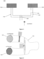
- FIGURE 1 illustrates a schematic diagram of a respiratory system 100 m one embodiment of the present disclosure.
- the respiratory system 100 comprises a plurality of components including but not limiting to a first pressure generating source 102, a second pressure generating source 104 and an interfacing assembly 106.
- the first pressure generating source 102 and the second pressure generating source 104 are configured to generate flow and pressure.
- the aforesaid pressure generating sources can be chosen from blowers, turbines, pumps, and the like. However, it is evident to a person of ordinary skills in the art that the type of patient interface tube and the pressure generating sources used does not limit the scope of present disclosure.
- the interfacing assembly 106 acts as a fluidic conduit between the aforesaid pressure/flow generators and the patient.
- the respiratory system 100 further includes a primary valve 108 and a control unit.
- the primary valve 108 is configured to switch between insufflation/positive pressure flow and exsufflation/negative pressure flow, and to generate oscillations in combination with the aforesaid insufflation and exsufflation cycles.
- a control unit is configured to control the aforesaid pressure generating sources and the primary valve 108 to generate a pressurized flow and oscillation as per the requirement of the user/patient.
- the respiratory system 100 includes a secondary valve 110 to generate oscillations along with either insufflation or exsufflation.
- the secondary valve 110 can be positioned in a positive air flow path 112 between the primary valve 108 and the first pressure generating source 102 to generate secondary oscillations during the negative pressure exsufflation cycle. It is to be noted that with said configuration, primary valve 108 can perform dual role, one is to switch between insufflation and exsufflation cycles and other is to generate primary exsufflation oscillations. Alternately, the secondary valve 110 can be positioned in a negative air flow path 114 between the primary valve 108 and the second pressure generating source 104 to generate secondary oscillations during the insufflation cycle. Note that with this configuration, the primary valve can perform dual role, one is to switch between insufflation and exsufflation cycles and other is to generate primary insufflation oscillations.
- the respiratory system 100 includes a rotary valve comprising a plurality of opening fluidly connected to the first pressure generating source 102 and the negative pressure generating source.
- FIGURE 2 is a schematic diagram illustrating a respiratory system 100 comprising a rotary valve with a plurality of openings.
- the respiratory system 100 includes a Y-shaped tube 118 for connecting the pressure generating sources 102, 104 to the interfacing assembly 106.
- any other appropriate tube known in the art can also be used in place of the Y-shaped tube.
- the primary valve is a two opening rotary valve 108' comprising a thin disc having two openings fluidly connected to the first pressure generating source 102 and the second pressure generating source 104 to selectively allow flow of air from either pressure generating sources.
- the two opening rotary valve is operated by a single motor with its shaft attached to the center 124 of said valve.
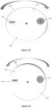
- FIGURE 3a, 3b , 3c, 3d , 3e, 3f , 3g and 3h illustrate a plurality of rotary positions of a two opening rotary valve 108' with respect to the positive and the negative pressure generating sources in accordance with an embodiment of the present subject matter.
- the two opening rotary valve 108' is positioned between the pressure generating sources 102, 104 and the interfacing assembly 106 to selectively allow pressurized air from the respective pressure generating sources to the interfacing assembly 106.
- the two opening rotary valve includes a first opening 120 and a second opening 122 which can be in fluid connection with the positive and negative pressure generating sources respectively.
- the first opening 120 can be circular in shape and the second opening 122 can be either rectangular or elliptical in shape.
- the shape of first and second opening 122 is only illustrative and not limiting the present subject matter. Further, the size of the first and second opening 122 can be either same or different.
- FIGURE 3b illustrates the two opening rotary valve, wherein the interfacing assembly 106 is fluidly disconnected from the first and second pressure generating source.
- the ⁇ first pressure generating source' of the present invention is also referred as the 'positive pressure generating source' and the 'second pressure generating source' is also referred as the 'negative pressure generating source' for the purpose of the present detailed description.
- FIGURE 3c illustrates a first position of the two opening rotary valve, wherein the interfacing assembly 106 is fluidly connected to the positive pressure generating source 102 through the second opening 122 and disconnected from the negative pressure generating source 104.
- the interfacing assembly 106 is fluidly connected to the positive pressure generating source 102 through the second opening 122 and disconnected from the negative pressure generating source 104.
- the negative pressure generating source 104 is completely blocked and the positive pressure generating source 102 completely overlaps with the second opening 122.
- Such an orientation is configured to generate only positive air flow or insufflation at the interfacing assembly 106.
- FIGURE 3d illustrates a second position of the two opening rotary valve, wherein the interfacing assembly 106 is fluidly connected to the negative pressure generating source 104 through the second opening 122 and disconnected from the positive pressure generating source 102.
- the interfacing assembly 106 is fluidly connected to the negative pressure generating source 104 through the second opening 122 and disconnected from the positive pressure generating source 102.
- the positive pressure generating source 102 is completely blocked and the negative pressure generating source 104 completely overlaps with the second opening 122.
- Such an orientation is configured to generate only negative air flow or exsufflation at the interfacing assembly 106.
- FIGURE 3e illustrates a third position of the two opening rotary valve.
- This orientation allows partial positive pressurized flow from the positive pressure generating source 102 to the interfacing assembly 106.
- the negative pressure generating source 104 is fluidly disconnected from the interfacing assembly 106.
- the fourth position allows a variable displacement from said fourth position and is configured to impart oscillations on top of positive pressure airflow.
- the position shown in FIGURE 3e is for illustration purpose only and in broader terms, such position refers to slight overlap of second opening 122 with the positive pressure generating source 102. Said overlap range can be any value between 1 % and 99%, the first opening 120 is fluidly disconnected from both the pressure generating sources.
- the two opening rotary valve in said orientation allows the positive pressure generating source 102 to undergo a variable displacement to impart oscillations through the positive pressure air flow.
- FIGURE 3f illustrates a fourth position of the two opening rotary valve.
- This orientation allows partial negative pressurized flow from negative pressure generating source 104 to the interfacing assembly 106.
- the positive pressure generating source 102 is fluidly disconnected from the interfacing assembly 106.
- the position shown in FIGURE 3f is for illustration purpose only and in broader terms, such position refers to slight overlap of second opening 122 with the negative pressure generating source 104. Said overlap can be any value between 1 % and 99%, the first opening 120 is fluidly disconnected from both the pressure generating sources.
- the two opening rotary valve in said orientation allows the negative pressure generating source 104 to undergo a variable displacement to impart oscillations through the negative pressure air flow.
- FIGURE 3g illustrates a fifth position of the two opening rotary valve.
- the second opening 122 completely overlaps with the positive pressure generating source 102 and allows complete positive pressurized flow to the interfacing assembly 106.
- the negative pressure generating source 104 partially overlaps with the first opening 120 and allows partial negative pressurized flow from negative pressure generating source 104 to the interfacing assembly 106.
- the position shown in FIGURE 3g is for illustration purpose only and in broader terms, the sixth position refers only to the second opening 122 completely fluidly connected to the positive pressure generating source 102 allowing positive pressurized flow to the interfacing assembly 106, and the first opening 120 fluidly partially overlaps with the negative pressure generating source 104.
- the two opening rotary valve in said orientation allows the negative pressure generating source 104 to undergo a variable displacement to impart oscillations through the negative pressure air flow. Further, said two opening rotary valve in said position also allows complete positive pressurized air flow or insufflation at the interfacing assembly 106.
- FIGURE 3h illustrates a sixth position of the two opening rotary valve.
- the second opening 122 completely overlaps the negative pressure generating source 104 and allows complete positive pressurized flow to the interfacing assembly 106.
- the positive pressure generating assembly partially overlaps with the first opening and allows partial positive pressurized flow from positive pressure generating source 102 to the interfacing assembly 106.
- the seventh position refers only to the second opening completely fluidly connected to the negative pressure generating source 104 allowing negative pressurized flow to the interfacing assembly 106, and the first opening 120 fluidly partially overlaps with the positive pressure generating source 102.
- the two opening rotary valve in said orientation allows the positive pressure generating source 102 to undergo a variable displacement to impart oscillations through the positive pressure air flow. Further, said two opening rotary valve in said position also allows complete negative pressurized air flow or exsufflation at the interfacing assembly 106.
- the respiratory system 100 described is capable of providing a multitude of therapies for respiratory patients.
- the control unit is configured to switch the two opening rotary valve between the first position ( FIGURE 3c ) and the second position ( FIGURE 3d ) which results in mechanical insufflation therapy.
- alternate switching between completely blocked position ( FIGURE 3b ) and third position ( FIGURE 3e ) results in a oscillation of positively pressurized flow
- alternating switching between completely blocked position ( FIGURE 3b ) and fourth position ( FIGURE 3f ) results in a oscillation of negatively pressurized flow. Amplitude of these oscillations is determined by how far the second opening and first opening 120 fluidly occlude the respective pressure generating sources.
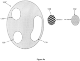
- the primary valve is a three-opening rotary valve 108" comprising a thin disc having three openings fluidly connected to the first pressure generating source 102 and the second pressure generating source 104 to selectively allow flow of air from either pressure generating sources.
- the disc is enclosed in a housing (not shown) with inlet and outlet ports corresponding to the negative and positive pressure generating sources.
- the three opening rotary valve is operated by a single stepper motor with its shaft attached to the center 124 of said valve.
- FIGURE 4a , 4b , 4c and 4d illustrate a plurality of rotary positions of a three opening rotary valve with respect to the positive and negative pressure generating sources in accordance with an embodiment of the present subject matter.
- the three opening rotary valve is positioned between the pressure generating sources and the interfacing assembly 106 to selectively allow pressurized air from the respective pressure generating sources to the interfacing assembly 106.
- the three opening rotary valve includes a first opening 126, a second opening 128 and a third opening 130 which can be in fluid connection with the positive and negative pressure generating sources.
- the first opening 126 and the second opening 128 can be circular in shape whereas the third opening 130 can be either rectangular or elliptical with straight sides.
- shape of the first, second and third opening 130 is only illustrative and not limiting the present subject matter. Further, the size of the first, second and third opening 130 can be either same or different.
- the center of the three opening rotary valve is connected with a shaft which enables the rotation of said valve.
- the first opening 126 is dedicated for negative pressure source.
- the first opening 126 rotates simultaneously with the second opening 128 on opposing side to close the negative pressure generating source 104 while the positive pressure generating source 102 is made open due to the rotary motion of the disc.
- the second opening 128 when operated in conjunction with the first opening 126 in opposing side, opens and closes the positive pressure source in opposing phase to the first opening 126.
- the third opening can oscillate the negative pressure generating source 104 from closed position while the second opening 128 keeps the positive pressure generating source 102 open due to its elongated shape.
- FIGURE 4b illustrates a first position of the three opening rotary valve, wherein only positive pressure generating source 102 is open and overlaps completely with the second opening 128.
- the three opening rotary valve in said orientation allows insufflation through the respiratory system 100.
- FIGURE 4c illustrates a second position of the three opening rotary valve. In this position, only negative pressure generating source 104 is open and overlaps completely with the first opening 126. The three opening rotary valve in said orientation allows exsufflation through the respiratory system 100. This position can also be oscillated for both positive and negative source at high frequency. Further, FIGURE 4d illustrates a third position of the three opening rotary valve wherein the third opening 130 completely overlaps with the positive pressure generating source 102 and the second opening 128 partially overlaps with the negative pressure generating source 104. Thus, the negative pressure generating source 104 oscillates and the positive pressure generating source 102 is completely open for insufflation.
- the invention doesn't limit other possible combination of valves and orientations to generate secondary oscillations on top of primary oscillations described. It is to be noted that with the help of additional secondary valve 110, secondary oscillations can be achieved on either on insufflation cycles or exsufflation cycles.
- the primary valve used to manipulate pressurized airflow is a voice coil based valve/voice coil valve.
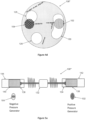
- FIGURE 5a , 5b, 5c, 5d , 5e, 5f and 5g illustrate a plurality of positions of voice coil plungers of a voice coil valve 108"' with respect to the positive and negative pressure generating sources in accordance with an embodiment of the present subject matter.
- the voice coil valve 108"' can be used for mechanical insufflation and exsufflation process in combination with the pressure generating sources.
- the voice coil valve includes a voice coil 132 with a first plunger 134 corresponding to the positive pressure generating source 102 and a second plunger 136 corresponding to the negative pressure generating source 104.
- the first and second plungers 134, 136 extend on both sides of the voice coil 132 and are supported by leaf springs. Each of the ends of the first and second plungers 134, 136 includes a first strip 138 and a second strip 140 respectively.
- the first strip 138 is capable of covering the opening of positive pressure generating source 102 and the second strip 140 is capable of covering the opening of negative pressure generating source 104.
- the voice coil valve 108"' further includes a first air tight housing 142 for axial movement of the first plunger 134 and a second air tight housing 144 for axial movement of the second plunger 136. Further, the first and second housing include two inlet ports and two outlet ports corresponding to the positive pressure generating source 102 and the negative pressure generating source 104 respectively.
- FIGURE 5b illustrates a first position of the voice coil valve with respect to the positive pressure generating source 102 and the negative pressure generating source 104.
- the first strip 138 does not cover the positive pressure generating source 102 and allows positive pressure air flow to the interfacing assembly 106.
- the second strip 140 completely covers the negative pressure generating source 104 and thus, the negative pressure airflow is fluidly disconnected from the interfacing assembly 106.
- the voice coil construction is for illustration purpose only. Other variations are possible to extend or lessen the dimension of the plungers and other structures described here to get the similar waveforms at the patient interface.
- FIGURE 5c illustrates a second position of the voice coil valve with respect to the positive pressure generating source 102 and the negative pressure generating source 104.
- the first strip 138 completely covers the positive pressure generating source 102 and the positive pressure air flow is disconnected from the interfacing assembly 106.
- the second strip 140 does not cover the negative pressure generating source 104 and thus allows negative pressure airflow to the interfacing assembly 106.
- FIGURE 5d illustrates a third position of the voice coil valve with respect to the positive pressure generating source 102 and the negative pressure generating source 104.
- the first strip 138 partially covers the positive pressure generating source 102 and allows positive pressure airflow to the interfacing assembly 106.
- the second strip 140 completely covers the negative pressure generating source 104 and negative airflow is fluidly disconnected from the interfacing assembly 106.
- Alternate back and forth operation between the first position ( FIGURE 5b ) and the third position ( FIGURE 5d ) results in oscillation of positive pressure generating source/positive pressure airflow.
- FIGURE 5e illustrates a fourth position of the voice coil valve with respect to the positive pressure generating source 102 and the negative pressure generating source 104.
- the first strip 138 completely covers the first pressure generating source 102 and the positive pressure airflow is fluidly disconnected from the interfacing assembly 106.
- the second strip 140 partially covers the negative pressure generating source 104 and fluidly, partially, allows negative pressure airflow to the interfacing assembly 106. Alternate back and forth operation between the second position ( FIGURE 5c ) and fourth position ( FIGURE 5e ) results in oscillation of negative pressure generating source/negative pressure flow.
- FIGURE 5f illustrates a fifth position of the voice coil valve with respect to the positive pressure generating source 102 and the negative pressure generating source 104.
- the first strip 138 does not cover the first pressure generating source 102 and the positive pressure airflow is fluidly completely connected to the interfacing assembly 106.
- the second strip 140 partially covers the negative pressure generating source 104 and fluidly, partially, allows negative pressure airflow to the interfacing assembly 106.
- Alternate back and forth operation between the first position ( FIGURE 5b ) and fifth position ( FIGURE 5f ) results in oscillation of negative pressure flow while the respiratory system 100 is in insufflation phase.
- FIGURE 5g illustrates a sixth position of the voice coil valve with respect to the positive pressure generating source 102 and the negative pressure generating source 104.
- the first strip 138 partially covers the first pressure generating source 102 and the positive pressure airflow is fluidly, partially, allows positive pressure airflow to the interfacing assembly 106.
- the second strip 140 does not cover the negative pressure generating source 104 and negative pressure airflow is fluidly completely connected to the interfacing assembly 106.
- Alternate back and forth operation between the second position ( FIGURE 5c ) and sixth position ( FIGURE 5g ) results in oscillation of positive pressure flow while device is in exsufflation phase.
- the respiratory system 100 further comprises a manifold/air router structure.
- the manifold/air router structure can be hollow cuboidal type, circular type, Y-shaped, cylindrical type or any other suitable manifold/air router structure type known in the art.
- the primary valve 108 structure is in fluid connection with the interfacing assembly 106 through the manifold/air router structure.
- the invention doesn't limit other possible combination of valves and orientations to generate secondary oscillations on top of primary oscillations described. It is to be noted that with the help of additional secondary valve 110, secondary oscillations can be achieved on either on insufflation cycles or exsufflation cycles.
- the respiratory system 100 of the present subject matter provides a unique opportunity to address the present challenges.
- the respiratory system 100 can deliver multitude of functions to assist patient with neuromuscular issues to manage their secretion.
Landscapes
- Health & Medical Sciences (AREA)
- Engineering & Computer Science (AREA)
- Pulmonology (AREA)
- Life Sciences & Earth Sciences (AREA)
- General Health & Medical Sciences (AREA)
- Biomedical Technology (AREA)
- Heart & Thoracic Surgery (AREA)
- Hematology (AREA)
- Emergency Medicine (AREA)
- Animal Behavior & Ethology (AREA)
- Anesthesiology (AREA)
- Public Health (AREA)
- Veterinary Medicine (AREA)
- General Engineering & Computer Science (AREA)
- Mechanical Engineering (AREA)
- Surgical Instruments (AREA)
- Percussion Or Vibration Massage (AREA)
- Multiple-Way Valves (AREA)
Description
- The present subject matter relates to a medical device in general, and in particular, the present invention relates to mechanical inexsufflation respiratory device which assists in the removal of secretions from patient airways.
- Patients having lung related diseases are unable to ventilate their lungs properly and may also suffer mucus clearance issues. This may happen when the normal lung defense system is damaged by lung related diseases.
- Many patients with neuromuscular weakness, spinal cord injury, as well as many other disorders associated with inability to control the full inhalation and explosive exhalation require mechanical assistance to cough or to remove their lung secretions.
- Generally, patients who have neuromuscular issues such as ineffective glottis closure, impaired diaphragm movement or weak respiratory muscles need mechanical assisted cough devices, i.e. Mechanical Insufflation/Exsufflation (M-IE). One of the well-known treatment modalities to treat these kind of patients is Mechanical insufflation and exsufflation device, which is well documented in prior art. For example, M-IE devices mimic/simulate the cough function, typically, for those patients who have a peak airflow lesser than 270 liters per minute, by providing a positive pressure air and suddenly creating a negative pressure inside the lung, which in turn brings the mucus along the upper airways. M-IE devices may also find their application in patients who have upper airway clearance issues after surgery, for example.
- In general, the existing secretion clearance devices provide an internal gas source as either internal blowers, turbines or some form of pumps.
- Out of the aforesaid devices, dual limb ventilation devices provide a patient circuit which has a dedicated limb for inspiratory gases or the gases going towards the lung and expiratory gases coming out of the lung. Such devices provide an internal positive pressure source while the expiration phase from the lung or external load is passive i.e. flow is generated by recoil of elastic lung and chest wall.
- International application
WO2007054829 A2 discloses a mechanical in-exsufflation device, comprising a patient interface unit configured to permit a negative pressure airflow therethrough and a positive pressure airflow from a medical mechanical ventilator; a suction unit for generating airflow under negative pressure that flows through the patient interface unit; a first valve for selectively blocking airflow from a medical mechanical ventilator to the patient interface unit; and a second valve separate from the first valve for selectively blocking airflow from the patient interface unit to the suction unit. - Further, a device known and used in the prior art for performing mechanical inexsufflation is the "CoughAssist®" from the JH Emerson Company of Cambridge, MA. The CoughAssist® device uses a turbine to perform insufflation of the lungs by blowing air into a patient at a defined pressure for a predetermined period of time through a tube connected to the patient's endotracheal tube, tracheostomy tube or facemask. After the predetermined period of time, a valve mechanism within the CoughAssist® device rapidly switches the direction of airflow within the length of tubing, resulting in rapid exsufflation of the patient's lungs. The exsufflation flow continues until the valve mechanism disconnects the tubing from the turbine, terminating the exsufflation flow. There is then a pause period, during which no airflow occurs and airway pressure is equal to zero (atmospheric pressure), until the next insufflation cycle commences. This pause period is necessary to avoid hyperventilation of the patient, and usually lasts about one to three seconds. The cycle is repeated several times to complete the secretion removal treatment. Further, the CoughAssist® device and other such available devices are unable to generate a range of oscillations in combination with the insufflation/exsufflation cycles.
-
US 2016/001033 A1 discloses a valve which comprises a housing in which a movable valve element having first and second valve members is disposed. A plurality of ports are disposed in the housing, and first and second seal portions are connected to the housing. The first and second seal portions each have a sealed configuration in which first and second pairs of ports are sealed from one another with the first and second valve members respectively. At least one of the first seal portion and the first valve member is deformable such that, when only the first seal portion is in the sealed configuration with the first valve member, deformation allows the second seal portion to be brought into the sealed configuration with the second valve member, and/or at least one the second seal portion and the second valve member is deformable such that, when only the second seal portion is in the sealed configuration with the second valve member, deformation allows the first seal portion to be brought into the sealed configuration with the first valve member. -
US 2003/051729 A1 refers to a manual inexsufflator including a standard mechanical ventilator, a medical suction unit, and a piston-like sliding valve mechanism which connects a patient ventilation interface with either the ventilator or the suction unit. By sliding the valve mechanism in and out the user selectively connects the patient to either the ventilator, for purposes of insufflation, or the suction unit, for purposes of exsufflation. The ventilator may generate expiratory positive airway pressure between inexsufflation cycles. -
US 2012/285460 A1 discloses to an MIE (mechanical insufflator/exsufflator) apparatus having a blower, a direction valve, an oscillator, and a mask hose connector. The blower is connected to the direction valve, which is connected to the oscillator, which is connected to the hose connector. During insufflation, a direction valve connects exhaust of a blower to an oscillator, causing positive pressure at the hose connector. During exsufflation, the direction valve connects the blower intake to the oscillator, causing negative pressure at the hose connector. The oscillator is a butterfly valve with a 360° rotating disc. During insufflation, the disc is fixed to steadily modulate the airflow. During exsufflation, the oscillator is inactive or in flutter mode. When inactive, the disc is fixed to allow maximum air flow. In flutter mode, the disc continuously rotates so that the air flow rapidly alternates between maximum and minimum. -
US 3 777 742 A discloses an apparatus for insufflating the airways of a patient with radiopaque powder, said apparatus comprising a container defining a chamber adapted to hold a pile of said powder, in insufflating circuit comprising an inlet line communicating with said chamber and also communicating with the atmosphere, said insufflating circuit also comprising an outlet line communicating with and leading from said chamber said outlet line being adapted to be sucked upon by the patient and constituting a means by which the patient may provide intermittant negative pressure in said chamber whereby, when the patient inhales, a stream of air is drawn into said chamber from said inlet line and flows through said chamber and into said outlet line for delivery into the airways of the patient, a cloud generating circuit comprising a pressure pump having inlet and outlet conduits, said outlet conduit being connected to the discharge side of said pump and being positioned with its discharge end located adjacent and directed toward said pile of powder whereby operation of said pump causes air to impinge against said pile and creates a cloud of powder within said chamber for entrainment in said air stream, and said inlet conduit being connected to the suction side of said pump and communicating with said chamber to keep the chamber substantially at atmospheric pressure and thereby prevent air and powder from being forced into said outlet line as a result of operation of said pump. -
US 2013/220325 A1 relates to a treatment device and method of use, and in particular to a treatment device adapted to assist the clearance of bronchial secretions in persons whose cough function is impaired. The invention provides a treatment device having a pump with a negative pressure inlet side and a positive pressure outlet side. The device has a breathing tube for connection to a patient, and a pressure sensor adapted to determine the pressure within the breathing tube. A valve selectively connects the breathing tube to the inlet side or the outlet side of the pump whereby to provide cycles of positive and negative pressure within the breathing tube. A controller is provided to control the valve. An indicator alerts the patient to an operational status of the device so that the patient can breathe in time with the device and in particular can seek to cough at the same time as the pressure within the breathing tube is rapidly reduced. - Hence, there is a need for a respiratory system which overcomes the aforementioned and other related challenges.
- The invention is defined by the appended claims.
- Subject-matter referred as embodiments and/or disclosures which are not covered by the appended claims are not part of the invention.
- It is an object of the present subject matter to provide a multitude of functions to clear patient's airway clearance.
- It is another object of the present subject matter to provide a positive pressure generating source.
- It is yet another object of the present subject matter to provide a negative pressure generating source.
- It is yet another object of the present subject matter to provide a primary valve to allow or block positive and negative airflow to a patient through an interfacing assembly.
- It is yet another object of the present subject matter to provide a two-opening rotary valve in fluid connection with the first pressure generating source and the second pressure generating source.
- It is yet another object of the present subject matter to provide a three-opening rotary valve in fluid connection with the first pressure generating source and the second pressure generating source.
- It is yet another object of the present subject matter to provide a voice coil based valve in fluid connection with the first pressure generating source and the second pressure generating source.
- It is yet another object of the present subject matter to provide mechanical insufflation/exsufflation.
- The respiratory system comprises a patient interface unit configured to permit either a negative pressure airflow or a positive pressure airflow to a patient interface, a negative pressure generating source for generating negative pressure airflow that flows through the patient interface unit, a positive pressure generating source for generating positive pressure airflow that flows through the patient interface unit and a first valve fluidly connected to said pressure generating sources for selectively blocking and/or unblocking airflow from either of the said pressure generating sources.
- In the present invention, said first valve is a rotary valve. The first valve, at a first position, is configured to block negative pressurized airflow at patient interface and allows the positive pressurized airflow to enter the patient interface. The first valve, at a second position, is configured to block the positive pressurized airflow at patient interface and allows the negative pressurized airflow to enter the patient interface. The first valve at a third position, with a variable displacement from said third position configured to impart oscillations on top of positive pressure airflow. The first valve at a fourth position, with a variable displacement from said fourth position configured to impart oscillations on top of negative pressure airflow.
- The pressure generating sources are connected to the patient interface unit by a tubing, wherein the tubing is a Y shaped tubing. The first valve comprises at least two or more openings of equal or varying sizes. The positive pressure generating source overlaps with either of the said openings to allow positive air flow at the patient interface. The negative pressure generating source overlaps with either of the said openings to allow negative air flow at the patient interface. The first valve is placed inside the respiratory system. The respiratory system further comprises a control unit to control operation of the said system. The control system is configured to generate insufflation and exsufflation waveforms by only operating the said first valve. The control system is further configured to generate oscillations on top of insufflation and exsufflation cycles, one at a time, by only operating the said first valve. The pressure generating sources are one or more of blowers, compressors.
- In an embodiment, the first valve is a linear motion valve, wherein the first valve comprises a voice coil having a first plunger and a second plunger. The ends of first and second plungers include a first strip and a second strip respectively. The first strip and the second strip are configured to block the pressure generating sources.
- airflow. The first valve at a fourth position, with a variable displacement from said fourth position configured to impart oscillations on top of negative pressure airflow. The first valve at a first position is configured to block negative pressurized airflow at patient interface and allows the positive pressurized airflow to enter the patient interface. The first valve at a second position is configured to block the positive pressurized airflow at patient interface and allows the negative pressurized airflow to enter the patient interface. The first valve at a third position, with a variable displacement from said third position configured to impart oscillations on top of positive pressure airflow. The first valve at a fourth position, with a variable displacement from said fourth position configured to impart oscillations on top of negative pressure airflow.
- A method of operating the respiratory system (not claimed) according to the present application comprises
generating positive pressure airflow/insufflation from a positive pressure generating source to the patient's interface/lung through a first valve, the first valve being in first orientation, wherein first position of the first valve selectively prevents negative pressurized airflow at the patient interface/lung, and allows the positive pressure airflow to enter patient interface/lung. Further, generating a negative pressure airflow/exsufflation by using negativepressure generating source 104 along patient interface/lung by using said first valve's second position, wherein second position of the valve selectively prevents positive pressure airflow from entering patient's interface/lung and allows the negative pressure airflow to enter patient interface/lung. Furthermore, the method comprises generating oscillation, either on top of said positive pressure airflow or on top of negative pressure airflow, by back and forth switching of the first valve from third position to fourth position. The step of switching the first valve from first position to second position is based on pre-determined time or pressure or volume parameters. The step of switching the first valve from second position to first position is based on pre-determined time or pressure or volume parameters. The positive pressurized flow ranges from 1 to 100 cmh20 as per the set parameters. The negative pressurized flow ranges from -1 to - 100 cmh20 as per the set parameters. The steps of changing the position of the valve, which are optionally automated, is electromechanical in nature. The steps of generating pressurized airflows at the patient interface comprise a defined sequence: positive pressure airflow, followed by positive pressured airflow of higher value, and ends with negative pressure airflow. The step of generating pressurized airflows at the patient interface comprises of a series of said sequence ranging from 1 to 50. - A respiratory system comprises a patient interface unit configured to permit either negative pressure airflow or positive pressure airflow to a patient interface. A negative pressure generating source is provided for generating negative pressure airflow that flows through the patient interface unit. A positive pressure generating source is provided for generating positive pressure airflow that flows through the patient interface unit. A first valve structure fluidly connected to said pressure generating source's airflow paths for selectively blocking and unblocking airflow from either of the said pressure generating sources. A second valve structure fluidly connected to a positive pressure airflow path and/or to a negative pressure airflow path to generate oscillations to said pressurized airflows. The first valve at first position blocks the negative pressure airflow at patient interface and allows the positive pressure airflow to enter the patient interface. The first valve at second position blocks the positive pressure airflow at patient interface and allows the negative pressure airflow to enter the patient interface. The first valve at third orientation with a variable displacement from said third orientation can impart oscillations on top of positive pressure airflow. The first valve at fourth orientation with a variable displacement from said fourth position can impart oscillations on top of negative pressure airflow. The second valve at first position with a variable displacement from said first position can impart oscillations on top of either of pressurized airflow path, depending on the location of the second valve. The second valve structure operationally can change its position from one location to other, either inside the positive pressure path or inside the negative pressure path to generate oscillations on respective pressured airflows.
- In an embodiment, the valves are rotary valves. The first position of valve can be a position where the valve can allow complete positive pressurize airflow to pass through it and block the negative pressure airflow from entering the patient interface. The second position of the valve can be a position where the valve can allow negative pressure airflow to pass through it and block the positive pressure airflow from entering the patient interface. The third position of the valve can be any position where the valve can allow complete or partial positive pressure airflow to pass through it and block the negative pressure airflow from entering the patient interface. The fourth position can be any position where the valve can block both positive pressure airflow and negative pressure airflow from patient interface. The fifth position of the valve can be any position where the valve can allow complete or partial negative pressure airflow to pass through it and block the positive pressure airflow from entering the patient interface. The sixth position can be any position where the valve can block both positive pressure airflow and negative pressure airflow from entering the patient interface. The first valve comprises at least two or more openings of equal or varying sizes. The first valve is placed in between the patient interface and second valve. The respiratory system further comprises a
control unit to control the operation of the said system. The control system is configured to generate insufflation and exsufflation waveforms by only operating the said first valve. - In an embodiment, the valve is linear valve. The linear motion valve can be made from voice coil. The control system is configured to generate oscillations on top of insufflation and exsufflation cycles, one at time, by only operating the said first valve. The control system is configured to generate oscillations on top of insufflation and exsufflation cycles, both at the same time, by using said two valves. The pressure generating sources are connected to the patient interface unit by a tube. In an embodiment, the tube is a Y-shaped tube.
- A method of operating the respiratory system according to the present application comprises: generating pressurized positive airflow/insufflation from a positive pressure generating source to the patient interface/lungs through a first valve, valve being in first position/orientation, wherein first position of the first valve selectively prevents entering negative pressure airflow from entering patient interface/lung. Further, generating a negative pressurized air flow/exsufflation by using negative pressure generating source at patient interface/lung by using said first valve's second position, wherein second position of the valve selectively prevents positive pressure airflow from entering patient lung. Furthermore, generating the oscillation either on top of said positive pressure airflow or on top of said negative pressure airflow by back and forth switching of the first valve from third position to fourth position and simultaneously generating the additional oscillation either of said pressured airflow by back and forth switching of the second valve from one position to other position. The step of switching the first valve from first position to second position is based on pre-determined time or pressure or volume parameters. The step of switching the first valve from second position to first position is based on pre-determined time or pressure or volume parameters. The step of switching the first valve from third position to fourth position and vice-versa is based on pre-determined frequency and oscillation amplitude requirements. The step of switching the first valve from fifth position to sixth position and vice-versa is based on pre-determined frequency and oscillation amplitude requirements. The step of switching the second valve from first position to any other position and vice-versa occurs based on pre-determined frequency and oscillation amplitude requirements. The positive pressurized flow ranges from 1 to 100 cmh20 as per the set parameters. The negative pressurized flow ranges from -1 to - 100 cmh20 as per the set parameters. The steps of changing the position of the valve, which are optionally automated, is electromechanical in nature. The steps of generating pressurized flows at the patient interface comprise a defined sequence: positive pressurized flow, followed by positive pressurized airflow of higher value, and end with negative pressurized flow. The defined sequence comprises of a series of said sequence ranging from 1 to 50. The pressure generating sources are one or more of blowers, compressors. The steps of generating oscillation comprises of generating an oscillation of
frequency 0 to 50 Hz and amplitude of 1 cmh20 to 100 cmh20. The second valve structure, operationally, can change its position from one location to other, either inside the positive pressure path or inside the negative pressure path to generate oscillations on respective pressured airflows. - A further understanding of the present subject matter can be obtained by reference to various embodiments set forth in the illustrations of the accompanying drawings. The drawings are not intended to limit the scope of the present subject matter, which is set forth with particularity in the claims as appended or as subsequently amended, but merely to clarify and exemplify the subject matter.
- For a fuller understanding of the nature and object of the present subject matter, reference is made to the accompanying drawings, wherein:
-
FIGURE 1 is a respiratory system in accordance with an embodiment of the present subject matter. -
FIGURE 2 is a schematic diagram illustrating a respiratory system comprising a rotary valve in accordance with an embodiment of the present subject matter. -
FIGURE 3a, 3b ,3c, 3d ,3e, 3f ,3g and 3h illustrate a plurality of rotary positions of a two opening rotary valve with respect to the positive and negative pressure generating sources in accordance with an embodiment of the present subject matter. -
FIGURE 4a ,4b ,4c and4d illustrate a plurality of rotary positions of a three opening rotary valve with respect to the positive and negative pressure generating sources in accordance with an embodiment of the present subject matter. -
FIGURE 5a ,5b, 5c, 5d ,5e, 5f and 5g illustrates a plurality of positions of voice coil plungers of a voice coil valve with respect to the positive and negative pressure generating sources in accordance with an embodiment of the present subject matter. - The following presents a detailed description of various embodiments of the present subject matter with reference to the accompanying drawings.
- As used herein, the singular forms "a", "an" and "the" are intended to include the plural forms as well, unless expressly stated otherwise. It will be further understood that the terms "includes", "comprises", "including" and/or "comprising" when used in this specification, specify the presence of stated features, integers, steps, operations, elements, and/or components, but do not preclude the presence or addition of one or more other features, integers, steps, operations, elements, components, and/or groups thereof. It will be understood that when an element is referred to as being "connected" or "coupled" to another element, it can be directly connected or coupled to the other element or intervening elements may be present. Furthermore, "connected" or "coupled" as used herein may include operatively connected or coupled. As used herein, the term "and/or" includes any and all combinations and arrangements of one or more of the associated listed items.
- The embodiments of the present subject matter are described in detail with reference to the accompanying drawings. However, the present subject matter is not limited to these embodiments which are only provided to explain more clearly the present subject matter to the ordinarily skilled in the art of the present disclosure. In the accompanying drawings, like reference numerals are used to indicate like components.
- Unless otherwise defined, all terms (including technical and scientific terms) used herein have the same meaning as commonly understood by one of ordinary skill in the art to which this disclosure pertains. It will be further understood that terms, such as those defined in commonly used dictionaries, should be interpreted as having a meaning that is consistent with their meaning in the context of the relevant art and will not be interpreted in an idealized or overly formal sense unless expressly so defined herein.
- The detailed description set forth below in connection with the appended drawings is intended as a description of the several presently contemplated embodiments of a respiratory system. The respiratory system is capable of providing multiple therapies for respiratory system, more specifically, for airway clearance. The apparatus can be configured to deliver various airway clearance therapies through hardware/mechanical, software and patient circuit configurations. This description is not intended to represent the only form in which the disclosed subject matter may be developed or utilized. The description sets forth the functions and features in connection with the illustrated embodiments. It is to be understood, however, that the same or equivalent functions may be accomplished by different embodiments that are also intended to be encompassed within the scope of the present disclosure. It is further understood that the use of relational terms such as first and second and the like are used solely to distinguish one from another entity without necessarily requiring or implying any actual such relationship or order between such entities.
- The respiratory system comprises two independent pressure generating sources, a valve to switch between insufflation/positive pressure flow and exsufflation/negative pressure flow, and to generate oscillations on top of either of these cycles. In other words, the valve can be used to generate oscillations along with switching between the insufflation/positive pressure flow and exsufflation/negative pressure flow.
- In order to generate secondary oscillations on top on insufflation and exsufflation oscillation cycles, the respiratory system can optionally employ a secondary valve either on a fluidic path of a positive pressure generating source or on a fluidic path of a negative flow generating source. A patient interface unit acts as a fluidic conduit between the pressure generating sources and the patient. A control unit which forms a part of the system is configured to generate required pressurized flow and oscillations as per the user settings. The aforesaid valves can be manipulated into a plurality of orientations/positions, which are aligned and/or adjusted with respect to the respective pressure generating sources as per the therapy requirements.
-
FIGURE 1 illustrates a schematic diagram of a respiratory system 100 m one embodiment of the present disclosure. Therespiratory system 100 comprises a plurality of components including but not limiting to a firstpressure generating source 102, a secondpressure generating source 104 and an interfacing assembly 106. The firstpressure generating source 102 and the secondpressure generating source 104 are configured to generate flow and pressure. The aforesaid pressure generating sources can be chosen from blowers, turbines, pumps, and the like. However, it is evident to a person of ordinary skills in the art that the type of patient interface tube and the pressure generating sources used does not limit the scope of present disclosure. The interfacing assembly 106 acts as a fluidic conduit between the aforesaid pressure/flow generators and the patient. Therespiratory system 100 further includes aprimary valve 108 and a control unit. Theprimary valve 108 is configured to switch between insufflation/positive pressure flow and exsufflation/negative pressure flow, and to generate oscillations in combination with the aforesaid insufflation and exsufflation cycles. A control unit is configured to control the aforesaid pressure generating sources and theprimary valve 108 to generate a pressurized flow and oscillation as per the requirement of the user/patient. Further, therespiratory system 100 includes asecondary valve 110 to generate oscillations along with either insufflation or exsufflation. Thesecondary valve 110 can be positioned in a positiveair flow path 112 between theprimary valve 108 and the firstpressure generating source 102 to generate secondary oscillations during the negative pressure exsufflation cycle. It is to be noted that with said configuration,primary valve 108 can perform dual role, one is to switch between insufflation and exsufflation cycles and other is to generate primary exsufflation oscillations. Alternately, thesecondary valve 110 can be positioned in a negativeair flow path 114 between theprimary valve 108 and the secondpressure generating source 104 to generate secondary oscillations during the insufflation cycle. Note that with this configuration, the primary valve can perform dual role, one is to switch between insufflation and exsufflation cycles and other is to generate primary insufflation oscillations. - In an embodiment, the
respiratory system 100 includes a rotary valve comprising a plurality of opening fluidly connected to the firstpressure generating source 102 and the negative pressure generating source.FIGURE 2 is a schematic diagram illustrating arespiratory system 100 comprising a rotary valve with a plurality of openings. Further, therespiratory system 100 includes a Y-shapedtube 118 for connecting thepressure generating sources - In an embodiment, the primary valve is a two opening rotary valve 108' comprising a thin disc having two openings fluidly connected to the first
pressure generating source 102 and the secondpressure generating source 104 to selectively allow flow of air from either pressure generating sources. The two opening rotary valve is operated by a single motor with its shaft attached to thecenter 124 of said valve.FIGURE 3a, 3b ,3c, 3d ,3e, 3f ,3g and 3h illustrate a plurality of rotary positions of a two opening rotary valve 108' with respect to the positive and the negative pressure generating sources in accordance with an embodiment of the present subject matter. The two opening rotary valve 108' is positioned between thepressure generating sources first opening 120 and asecond opening 122 which can be in fluid connection with the positive and negative pressure generating sources respectively. Thefirst opening 120 can be circular in shape and thesecond opening 122 can be either rectangular or elliptical in shape. However, the shape of first andsecond opening 122 is only illustrative and not limiting the present subject matter. Further, the size of the first andsecond opening 122 can be either same or different. Thecenter 124 of the two-opening rotary valve is connected to a shaft (not shown) which enables the rotation of said valve.FIGURE 3b illustrates the two opening rotary valve, wherein the interfacing assembly 106 is fluidly disconnected from the first and second pressure generating source. The `first pressure generating source' of the present invention is also referred as the 'positive pressure generating source' and the 'second pressure generating source' is also referred as the 'negative pressure generating source' for the purpose of the present detailed description. -
FIGURE 3c illustrates a first position of the two opening rotary valve, wherein the interfacing assembly 106 is fluidly connected to the positivepressure generating source 102 through thesecond opening 122 and disconnected from the negativepressure generating source 104. In other words, only the negativepressure generating source 104 is completely blocked and the positivepressure generating source 102 completely overlaps with thesecond opening 122.
Such an orientation is configured to generate only positive air flow or insufflation at the interfacing assembly 106. -
FIGURE 3d illustrates a second position of the two opening rotary valve, wherein the interfacing assembly 106 is fluidly connected to the negativepressure generating source 104 through thesecond opening 122 and disconnected from the positivepressure generating source 102. In other words, only the positivepressure generating source 102 is completely blocked and the negativepressure generating source 104 completely overlaps with thesecond opening 122. Such an orientation is configured to generate only negative air flow or exsufflation at the interfacing assembly 106. -
FIGURE 3e illustrates a third position of the two opening rotary valve. This orientation allows partial positive pressurized flow from the positivepressure generating source 102 to the interfacing assembly 106. The negativepressure generating source 104 is fluidly disconnected from the interfacing assembly 106. The fourth position allows a variable displacement from said fourth position and is configured to impart oscillations on top of positive pressure airflow. However, it is evident to a person skilled in the art that the position shown inFIGURE 3e is for illustration purpose only and in broader terms, such position refers to slight overlap ofsecond opening 122 with the positivepressure generating source 102. Said overlap range can be any value between 1 % and 99%, thefirst opening 120 is fluidly disconnected from both the pressure generating sources. The two opening rotary valve in said orientation allows the positivepressure generating source 102 to undergo a variable displacement to impart oscillations through the positive pressure air flow. -
FIGURE 3f illustrates a fourth position of the two opening rotary valve. This orientation allows partial negative pressurized flow from negativepressure generating source 104 to the interfacing assembly 106. The positivepressure generating source 102 is fluidly disconnected from the interfacing assembly 106. However, it is evident to a person skilled in the art that the position shown inFIGURE 3f is for illustration purpose only and in broader terms, such position refers to slight overlap ofsecond opening 122 with the negativepressure generating source 104. Said overlap can be any value between 1 % and 99%, thefirst opening 120 is fluidly disconnected from both the pressure generating sources. The two opening rotary valve in said orientation allows the negativepressure generating source 104 to undergo a variable displacement to impart oscillations through the negative pressure air flow. -
FIGURE 3g illustrates a fifth position of the two opening rotary valve. In this position, thesecond opening 122 completely overlaps with the positivepressure generating source 102 and allows complete positive pressurized flow to the interfacing assembly 106. The negativepressure generating source 104 partially overlaps with thefirst opening 120 and allows partial negative pressurized flow from negativepressure generating source 104 to the interfacing assembly 106. However, it is evident to a person skilled in the art that the position shown inFIGURE 3g is for illustration purpose only and in broader terms, the sixth position refers only to thesecond opening 122 completely fluidly connected to the positivepressure generating source 102 allowing positive pressurized flow to the interfacing assembly 106, and thefirst opening 120 fluidly partially overlaps with the negativepressure generating source 104. The two opening rotary valve in said orientation allows the negativepressure generating source 104 to undergo a variable displacement to impart oscillations through the negative pressure air flow. Further, said two opening rotary valve in said position also allows complete positive pressurized air flow or insufflation at the interfacing assembly 106. -
FIGURE 3h illustrates a sixth position of the two opening rotary valve. In this position, thesecond opening 122 completely overlaps the negativepressure generating source 104 and allows complete positive pressurized flow to the interfacing assembly 106. The positive pressure generating assembly partially overlaps with the first opening and allows partial positive pressurized flow from positivepressure generating source 102 to the interfacing assembly 106. However, it is evident to a person skilled in the art that the position shown inFIGURE 3h is for illustration purpose only and in broader terms, the seventh position refers only to the second opening completely fluidly connected to the negativepressure generating source 104 allowing negative pressurized flow to the interfacing assembly 106, and thefirst opening 120 fluidly partially overlaps with the positivepressure generating source 102. The two opening rotary valve in said orientation allows the positivepressure generating source 102 to undergo a variable displacement to impart oscillations through the positive pressure air flow. Further, said two opening rotary valve in said position also allows complete negative pressurized air flow or exsufflation at the interfacing assembly 106. - The
respiratory system 100 described is capable of providing a multitude of therapies for respiratory patients. In operation, the control unit is configured to switch the two opening rotary valve between the first position (FIGURE 3c ) and the second position (FIGURE 3d ) which results in mechanical insufflation therapy. Further, alternate switching between completely blocked position (FIGURE 3b ) and third position (FIGURE 3e ) results in a oscillation of positively pressurized flow and alternating switching between completely blocked position (FIGURE 3b ) and fourth position (FIGURE 3f ) results in a oscillation of negatively pressurized flow. Amplitude of these oscillations is determined by how far the second opening andfirst opening 120 fluidly occlude the respective pressure generating sources. Furthermore, alternate switching between the first position (FIGURE 3c ) and the fifth position (FIGURE 3g ) results in oscillation through negatively pressured flow and alternate switching between second position (FIGURE 3d ) and sixth position (FIGURE 3h ) results in oscillation through positively pressured flow. The invention doesn't limit other possible combination of valves and orientations to generate secondary oscillations on top of primary oscillations described. It is to be noted that with the help of the additionalsecondary valve 110, secondary oscillations can be achieved on either on insufflation cycles or exsufflation cycles. - In an embodiment, the primary valve is a three-opening
rotary valve 108" comprising a thin disc having three openings fluidly connected to the firstpressure generating source 102 and the secondpressure generating source 104 to selectively allow flow of air from either pressure generating sources. The disc is enclosed in a housing (not shown) with inlet and outlet ports corresponding to the negative and positive pressure generating sources. The three opening rotary valve is operated by a single stepper motor with its shaft attached to thecenter 124 of said valve.FIGURE 4a ,4b ,4c and4d illustrate a plurality of rotary positions of a three opening rotary valve with respect to the positive and negative pressure generating sources in accordance with an embodiment of the present subject matter. The three opening rotary valve is positioned between the pressure generating sources and the interfacing assembly 106 to selectively allow pressurized air from the respective pressure generating sources to the interfacing assembly 106. The three opening rotary valve includes afirst opening 126, asecond opening 128 and athird opening 130 which can be in fluid connection with the positive and negative pressure generating sources. Thefirst opening 126 and thesecond opening 128 can be circular in shape whereas thethird opening 130 can be either rectangular or elliptical with straight sides. However, shape of the first, second andthird opening 130 is only illustrative and not limiting the present subject matter. Further, the size of the first, second andthird opening 130 can be either same or different. The center of the three opening rotary valve is connected with a shaft which enables the rotation of said valve. Thefirst opening 126 is dedicated for negative pressure source. Upon rotation of the three opening rotary valve, thefirst opening 126 rotates simultaneously with thesecond opening 128 on opposing side to close the negativepressure generating source 104 while the positivepressure generating source 102 is made open due to the rotary motion of the disc. Thesecond opening 128 when operated in conjunction with thefirst opening 126 in opposing side, opens and closes the positive pressure source in opposing phase to thefirst opening 126. Further, the third opening can oscillate the negativepressure generating source 104 from closed position while thesecond opening 128 keeps the positivepressure generating source 102 open due to its elongated shape.FIGURE 4b illustrates a first position of the three opening rotary valve, wherein only positivepressure generating source 102 is open and overlaps completely with thesecond opening 128. The three opening rotary valve in said orientation allows insufflation through therespiratory system 100. -
FIGURE 4c illustrates a second position of the three opening rotary valve. In this position, only negativepressure generating source 104 is open and overlaps completely with thefirst opening 126. The three opening rotary valve in said orientation allows exsufflation through therespiratory system 100. This position can also be oscillated for both positive and negative source at high frequency. Further,FIGURE 4d illustrates a third position of the three opening rotary valve wherein thethird opening 130 completely overlaps with the positivepressure generating source 102 and thesecond opening 128 partially overlaps with the negativepressure generating source 104. Thus, the negativepressure generating source 104 oscillates and the positivepressure generating source 102 is completely open for insufflation. The invention doesn't limit other possible combination of valves and orientations to generate secondary oscillations on top of primary oscillations described. It is to be noted that with the help of additionalsecondary valve 110, secondary oscillations can be achieved on either on insufflation cycles or exsufflation cycles. - In an embodiment, the primary valve used to manipulate pressurized airflow is a voice coil based valve/voice coil valve.
FIGURE 5a ,5b, 5c, 5d ,5e, 5f and 5g illustrate a plurality of positions of voice coil plungers of avoice coil valve 108"' with respect to the positive and negative pressure generating sources in accordance with an embodiment of the present subject matter. Thevoice coil valve 108"' can be used for mechanical insufflation and exsufflation process in combination with the pressure generating sources. The voice coil valve includes avoice coil 132 with afirst plunger 134 corresponding to the positivepressure generating source 102 and asecond plunger 136 corresponding to the negativepressure generating source 104. The first andsecond plungers voice coil 132 and are supported by leaf springs. Each of the ends of the first andsecond plungers first strip 138 and asecond strip 140 respectively. Thefirst strip 138 is capable of covering the opening of positivepressure generating source 102 and thesecond strip 140 is capable of covering the opening of negativepressure generating source 104. Thevoice coil valve 108"' further includes a first airtight housing 142 for axial movement of thefirst plunger 134 and a second airtight housing 144 for axial movement of thesecond plunger 136. Further, the first and second housing include two inlet ports and two outlet ports corresponding to the positivepressure generating source 102 and the negativepressure generating source 104 respectively.FIGURE 5b illustrates a first position of the voice coil valve with respect to the positivepressure generating source 102 and the negativepressure generating source 104. In this position, thefirst strip 138 does not cover the positivepressure generating source 102 and allows positive pressure air flow to the interfacing assembly 106. Thesecond strip 140 completely covers the negativepressure generating source 104 and thus, the negative pressure airflow is fluidly disconnected from the interfacing assembly 106. It is to be noted that the voice coil construction is for illustration purpose only. Other variations are possible to extend or lessen the dimension of the plungers and other structures described here to get the similar waveforms at the patient interface. -
FIGURE 5c illustrates a second position of the voice coil valve with respect to the positivepressure generating source 102 and the negativepressure generating source 104. In this position, thefirst strip 138 completely covers the positivepressure generating source 102 and the positive pressure air flow is disconnected from the interfacing assembly 106. Thesecond strip 140 does not cover the negativepressure generating source 104 and thus allows negative pressure airflow to the interfacing assembly 106. - Further,
FIGURE 5d illustrates a third position of the voice coil valve with respect to the positivepressure generating source 102 and the negativepressure generating source 104. In this position, thefirst strip 138 partially covers the positivepressure generating source 102 and allows positive pressure airflow to the interfacing assembly 106. Thesecond strip 140 completely covers the negativepressure generating source 104 and negative airflow is fluidly disconnected from the interfacing assembly 106. Alternate back and forth operation between the first position (FIGURE 5b ) and the third position (FIGURE 5d ) results in oscillation of positive pressure generating source/positive pressure airflow. -
FIGURE 5e illustrates a fourth position of the voice coil valve with respect to the positivepressure generating source 102 and the negativepressure generating source 104. In this position, thefirst strip 138 completely covers the firstpressure generating source 102 and the positive pressure airflow is fluidly disconnected from the interfacing assembly 106. Thesecond strip 140 partially covers the negativepressure generating source 104 and fluidly, partially, allows negative pressure airflow to the interfacing assembly 106. Alternate back and forth operation between the second position (FIGURE 5c ) and fourth position (FIGURE 5e ) results in oscillation of negative pressure generating source/negative pressure flow. -
FIGURE 5f illustrates a fifth position of the voice coil valve with respect to the positivepressure generating source 102 and the negativepressure generating source 104. In this position, thefirst strip 138 does not cover the firstpressure generating source 102 and the positive pressure airflow is fluidly completely connected to the interfacing assembly 106. Thesecond strip 140 partially covers the negativepressure generating source 104 and fluidly, partially, allows negative pressure airflow to the interfacing assembly 106. Alternate back and forth operation between the first position (FIGURE 5b ) and fifth position (FIGURE 5f ) results in oscillation of negative pressure flow while therespiratory system 100 is in insufflation phase. -
FIGURE 5g illustrates a sixth position of the voice coil valve with respect to the positivepressure generating source 102 and the negativepressure generating source 104. In this position, thefirst strip 138 partially covers the firstpressure generating source 102 and the positive pressure airflow is fluidly, partially, allows positive pressure airflow to the interfacing assembly 106. Thesecond strip 140 does not cover the negativepressure generating source 104 and negative pressure airflow is fluidly completely connected to the interfacing assembly 106. Alternate back and forth operation between the second position (FIGURE 5c ) and sixth position (FIGURE 5g ) results in oscillation of positive pressure flow while device is in exsufflation phase. - In an embodiment, the
respiratory system 100 further comprises a manifold/air router structure. The manifold/air router structure can be hollow cuboidal type, circular type, Y-shaped, cylindrical type or any other suitable manifold/air router structure type known in the art. However, it is evident to a person of ordinary skills in the art that the type of manifold/air router structure used does not limit the scope of the present disclosure. Theprimary valve 108 structure is in fluid connection with the interfacing assembly 106 through the manifold/air router structure. As with the rotary valve structure, the invention doesn't limit other possible combination of valves and orientations to generate secondary oscillations on top of primary oscillations described. It is to be noted that with the help of additionalsecondary valve 110, secondary oscillations can be achieved on either on insufflation cycles or exsufflation cycles. - As described hereinabove, the
respiratory system 100 of the present subject matter provides a unique opportunity to address the present challenges. Therespiratory system 100 can deliver multitude of functions to assist patient with neuromuscular issues to manage their secretion. - Although the disclosure has been described with reference to specific embodiments, this description is not meant to be construed in a limiting sense.
Claims (12)
- A respiratory system (100) comprising: a patient interface unit configured to permit either a negative pressure airflow or a positive pressure airflow to a patient; a negative pressure generating source (104) for generating negative pressure airflow that flows through the patient interface unit; a positive pressure generating source (102) for generating positive pressure airflow that flows through the patient interface unit; and a first valve fluidly (108) connected to said pressure generating sources for selectively blocking and/or unblocking airflow from either of the said pressure generating sources, wherein said first valve at a first position, is configured to block the negative pressure airflow at a patient interface and allows the positive pressure airflow to enter the patient interface, said first valve at a second position, configured to block the positive pressure airflow at the patient interface and allows the negative pressure airflow to enter the patient interface, said first valve at a third position, with a variable displacement from said third position configured to impart oscillations on top of the positive pressure airflow, said first valve at a fourth position, with a variable displacement from said fourth position configured to impart oscillations on top of the negative pressure airflow wherein said pressure generating sources are connected to the patient interface unit by a Y-shaped tube, and wherein the first valve is a rotary valve comprising a thin disc having at least two or more openings of equal or varying sizes.
- A respiratory system (100) according to claim 1 further comprising: a second valve structure fluidly connected to a positive pressure airflow path and/or to a negative pressure airflow path to generate oscillations to said pressurized airflows.
- The respiratory system (100) as claimed in claim 1, wherein the positive pressure generating source (102) overlaps with either of the said openings to allow positive air flow at the patient interface.
- The respiratory system (100) as claimed in claim 1, wherein the negative pressure generating source (104) overlaps with either of the said openings to allow negative air flow at the patient interface.
- The respiratory system (100) as claimed in claim 1, wherein said first valve is placed inside the respiratory system (100).
- The respiratory system (100) as claimed in claim 1 or 2, further comprising a control unit to control operation of the said system and wherein optionally control system is configured to generate insufflation and exsufflation waveforms by only operating the said first valve and wherein optionally control system is configured to generate oscillations on top of insufflation and exsufflation cycles, one at a time, by only operating the said first valve.
- The respiratory system (100) as claimed in claim 1, wherein the pressure generating sources are one or more of blowers, compressors.
- The respiratory system (100) as claimed in claim 1 or 2, wherein the valves are linear motion valves.
- The respiratory system (100) as claimed in claim 2, wherein said second valve at first position with a variable displacement from said first position can impart pressure oscillations in either of pressurized airflow paths, depending on the location of the second valve.
- The respiratory system (100) as claimed in claim 2, wherein said second valve structure, operationally can change its position from one location to other, either inside the positive pressure path or inside the negative pressure path to generate oscillations on respective pressured airflows.
- The respiratory system (100) as claimed in claim 1, wherein first position of valve being a position where the valve can allow complete positive pressurize airflow to pass through it and block the negative pressure airflow from entering the patient interface and/or wherein second position of the valve can be a position where the valve can allow negative pressure airflow to pass through it and block the positive pressure airflow from entering the patient interface and/or wherein third position of the valve can be any position where the valve can allow complete or partial positive pressure airflow to pass through it and block the negative pressure airflow from entering the patient interface and/or wherein fourth position can be any position where the valve can block both positive pressure airflow and negative pressure airflow from patient interface and/or wherein fifth position of the valve can be any position where the valve can allow complete or partial negative pressure airflow to pass through it and block the positive pressure airflow from entering the patient interface and/or wherein sixth position can be any position where the valve can block both positive pressure airflow and negative pressure airflow from entering the patient interface.
- The respiratory system (100) as claimed in claim 10, wherein the control system is configured to generate oscillations on top of insufflation and exsufflation cycles, both at the same time, by using said two valves.
Applications Claiming Priority (2)
| Application Number | Priority Date | Filing Date | Title |
|---|---|---|---|
| IN201741011674 | 2017-03-31 | ||
| PCT/IB2018/052035 WO2018178841A2 (en) | 2017-03-31 | 2018-03-26 | A respiratory system |
Publications (3)
| Publication Number | Publication Date |
|---|---|
| EP3600506A2 EP3600506A2 (en) | 2020-02-05 |
| EP3600506A4 EP3600506A4 (en) | 2021-01-13 |
| EP3600506B1 true EP3600506B1 (en) | 2024-10-09 |
Family
ID=63674319
Family Applications (1)
| Application Number | Title | Priority Date | Filing Date |
|---|---|---|---|
| EP18777735.4A Active EP3600506B1 (en) | 2017-03-31 | 2018-03-26 | A respiratory system |
Country Status (4)
| Country | Link |
|---|---|
| US (1) | US11642479B2 (en) |
| EP (1) | EP3600506B1 (en) |
| AU (1) | AU2018247142B2 (en) |
| WO (1) | WO2018178841A2 (en) |
Families Citing this family (2)
| Publication number | Priority date | Publication date | Assignee | Title |
|---|---|---|---|---|
| WO2020225817A1 (en) * | 2019-05-08 | 2020-11-12 | Respinova Ltd. | A system for delivering inhaled therapies |
| DE102023113442A1 (en) * | 2022-06-01 | 2023-12-07 | Löwenstein Medical Technology S.A. | VENTILATOR WITH TWO SERIAL FANS |
Family Cites Families (17)
| Publication number | Priority date | Publication date | Assignee | Title |
|---|---|---|---|---|
| US3777742A (en) | 1972-09-18 | 1973-12-11 | Barber Colman Co | Tantalum insufflator |
| EP0325200B1 (en) * | 1988-01-18 | 1994-04-13 | Hitachi, Ltd. | Rotary valve |
| JPH06312158A (en) * | 1993-04-30 | 1994-11-08 | Matsui Mfg Co | Air vibration wave generation method and apparatus |
| JP3945902B2 (en) * | 1998-03-31 | 2007-07-18 | スズキ株式会社 | Ventilator |
| US7597670B2 (en) * | 1999-07-02 | 2009-10-06 | Warwick Warren J | Chest compression apparatus |
| IL145461A (en) | 2001-09-16 | 2006-09-05 | Alyn Woldenberg Family Hospita | Inexsufflator |
| AU2006313454A1 (en) | 2005-09-26 | 2007-05-18 | Innovent Medical Solutions, Inc. | Combined ventilator inexsufflator |
| WO2012042255A1 (en) | 2010-09-28 | 2012-04-05 | Noel Martin Davis | Treatment device and method of use |
| US8539952B2 (en) * | 2011-05-13 | 2013-09-24 | Hill-Rom Services Pte. Ltd. | Mechanical insufflation/exsufflation airway clearance apparatus |
| JP6101703B2 (en) * | 2011-12-14 | 2017-03-22 | コーニンクレッカ フィリップス エヌ ヴェKoninklijke Philips N.V. | Reversing valve and high frequency vibration airflow generator |
| EP2827929B1 (en) * | 2012-03-21 | 2021-05-12 | Koninklijke Philips N.V. | Bi-directional flow generation in an in-exsufflation system |
| US10213575B2 (en) | 2013-03-07 | 2019-02-26 | Koninklijke Philips N.V. | Valve |
| US20160151232A1 (en) * | 2014-09-22 | 2016-06-02 | Respirtech | Hfcc therapy system providing device adherence data |
| EP3237048A1 (en) * | 2014-12-26 | 2017-11-01 | Koninklijke Philips N.V. | Secretion loosening and cough segmenting therapy |
| JP6480598B2 (en) * | 2015-04-02 | 2019-03-13 | ヒル−ロム サービシーズ プライヴェート リミテッド | Respirator manifold |
| US10518048B2 (en) * | 2015-07-31 | 2019-12-31 | Hill-Rom Services, PTE Ltd. | Coordinated control of HFCWO and cough assist devices |
| US10773049B2 (en) * | 2016-06-21 | 2020-09-15 | Ventec Life Systems, Inc. | Cough-assist systems with humidifier bypass |
-
2018
- 2018-03-26 AU AU2018247142A patent/AU2018247142B2/en active Active
- 2018-03-26 US US16/606,714 patent/US11642479B2/en active Active
- 2018-03-26 WO PCT/IB2018/052035 patent/WO2018178841A2/en not_active Ceased
- 2018-03-26 EP EP18777735.4A patent/EP3600506B1/en active Active
Also Published As
| Publication number | Publication date |
|---|---|
| US20210290876A1 (en) | 2021-09-23 |
| WO2018178841A3 (en) | 2019-01-03 |
| EP3600506A4 (en) | 2021-01-13 |
| AU2018247142B2 (en) | 2024-01-11 |
| US11642479B2 (en) | 2023-05-09 |
| AU2018247142A1 (en) | 2019-11-21 |
| EP3600506A2 (en) | 2020-02-05 |
| WO2018178841A2 (en) | 2018-10-04 |
Similar Documents
| Publication | Publication Date | Title |
|---|---|---|
| JP7324910B2 (en) | pressure regulating valve | |
| US7063086B2 (en) | Breathing assistance apparatus | |
| US12569633B2 (en) | Oscillatory respiratory care apparatus | |
| JP5184534B2 (en) | Ventilation device and method that allows a patient to speak with or without a tracheostomy tube check valve | |
| JP5394242B2 (en) | Pressure reducing valve | |
| US20070186928A1 (en) | Combined ventilator inexsufflator | |
| US10166360B2 (en) | System and method for controlling flow during exhalation in a respiratory support system | |
| EP2945677B1 (en) | System for controlling airway gas parameters during high frequency positive pressure ventilation | |
| US11446454B2 (en) | Device for respiratory therapy | |
| EP2827929B1 (en) | Bi-directional flow generation in an in-exsufflation system | |
| CN104203320B (en) | Systems and methods for controlling insufflation pressure during insufflation | |
| EP3041558B1 (en) | Apparatus to provide breathing support | |
| JP2010502402A5 (en) | ||
| JP2007500562A (en) | Device for non-invasive artificial respiration | |
| WO2019243758A1 (en) | Respiratory therapy devices and assemblies | |
| US11642479B2 (en) | Respiratory system | |
| CN111886042A (en) | Miniature two-way valve and system | |
| CN111330122A (en) | Breathing machine with expectoration vibrates function | |
| CN112704789A (en) | High-frequency oscillation respiratory airflow generation method and respiratory support equipment | |
| JPH02131774A (en) | Respiratory oscillation generator in artificial respiratory organs | |
| WO2020225817A1 (en) | A system for delivering inhaled therapies | |
| JP4625640B2 (en) | Cuffed tube | |
| SU1183096A1 (en) | Apparatus for artificial ventilation of the lungs | |
| HK1177436A1 (en) | Breathing-gas delivery and sharing system and method |
Legal Events
| Date | Code | Title | Description |
|---|---|---|---|
| STAA | Information on the status of an ep patent application or granted ep patent |
Free format text: STATUS: THE INTERNATIONAL PUBLICATION HAS BEEN MADE |
|
| PUAI | Public reference made under article 153(3) epc to a published international application that has entered the european phase |
Free format text: ORIGINAL CODE: 0009012 |
|
| STAA | Information on the status of an ep patent application or granted ep patent |
Free format text: STATUS: REQUEST FOR EXAMINATION WAS MADE |
|
| 17P | Request for examination filed |
Effective date: 20191029 |
|
| AK | Designated contracting states |
Kind code of ref document: A2 Designated state(s): AL AT BE BG CH CY CZ DE DK EE ES FI FR GB GR HR HU IE IS IT LI LT LU LV MC MK MT NL NO PL PT RO RS SE SI SK SM TR |
|
| AX | Request for extension of the european patent |
Extension state: BA ME |
|
| DAV | Request for validation of the european patent (deleted) | ||
| DAX | Request for extension of the european patent (deleted) | ||
| A4 | Supplementary search report drawn up and despatched |
Effective date: 20201214 |
|
| RIC1 | Information provided on ipc code assigned before grant |
Ipc: A61M 16/20 20060101ALI20201208BHEP Ipc: F16K 11/052 20060101ALI20201208BHEP Ipc: A61M 16/08 20060101ALI20201208BHEP Ipc: A61M 16/00 20060101AFI20201208BHEP Ipc: A61M 16/04 20060101ALI20201208BHEP |
|
| STAA | Information on the status of an ep patent application or granted ep patent |
Free format text: STATUS: EXAMINATION IS IN PROGRESS |
|
| 17Q | First examination report despatched |
Effective date: 20230801 |
|
| REG | Reference to a national code |
Ref country code: DE Ref legal event code: R079 Free format text: PREVIOUS MAIN CLASS: A61M0016000000 Ipc: F16K0011074000 Ref country code: DE Ref legal event code: R079 Ref document number: 602018075229 Country of ref document: DE Free format text: PREVIOUS MAIN CLASS: A61M0016000000 Ipc: F16K0011074000 |
|
| GRAP | Despatch of communication of intention to grant a patent |
Free format text: ORIGINAL CODE: EPIDOSNIGR1 |
|
| RIC1 | Information provided on ipc code assigned before grant |
Ipc: A61M 16/20 20060101ALI20240319BHEP Ipc: A61M 16/08 20060101ALI20240319BHEP Ipc: A61M 16/04 20060101ALI20240319BHEP Ipc: A61M 16/00 20060101ALI20240319BHEP Ipc: F16K 11/074 20060101AFI20240319BHEP |
|
| STAA | Information on the status of an ep patent application or granted ep patent |
Free format text: STATUS: GRANT OF PATENT IS INTENDED |
|
| INTG | Intention to grant announced |
Effective date: 20240425 |
|
| GRAS | Grant fee paid |
Free format text: ORIGINAL CODE: EPIDOSNIGR3 |
|
| GRAA | (expected) grant |
Free format text: ORIGINAL CODE: 0009210 |
|
| STAA | Information on the status of an ep patent application or granted ep patent |
Free format text: STATUS: THE PATENT HAS BEEN GRANTED |
|
| AK | Designated contracting states |
Kind code of ref document: B1 Designated state(s): AL AT BE BG CH CY CZ DE DK EE ES FI FR GB GR HR HU IE IS IT LI LT LU LV MC MK MT NL NO PL PT RO RS SE SI SK SM TR |
|
| RAP1 | Party data changed (applicant data changed or rights of an application transferred) |
Owner name: ABM RESPIRATORY CARE PTE. LTD. |
|
| RIN1 | Information on inventor provided before grant (corrected) |
Inventor name: TRIVIKRAM |
|
| REG | Reference to a national code |
Ref country code: CH Ref legal event code: EP |
|
| REG | Reference to a national code |
Ref country code: DE Ref legal event code: R096 Ref document number: 602018075229 Country of ref document: DE |
|
| REG | Reference to a national code |
Ref country code: IE Ref legal event code: FG4D |
|
| REG | Reference to a national code |
Ref country code: LT Ref legal event code: MG9D |
|
| REG | Reference to a national code |
Ref country code: NL Ref legal event code: MP Effective date: 20241009 |
|
| REG | Reference to a national code |
Ref country code: AT Ref legal event code: MK05 Ref document number: 1730920 Country of ref document: AT Kind code of ref document: T Effective date: 20241009 |
|
| PG25 | Lapsed in a contracting state [announced via postgrant information from national office to epo] |
Ref country code: NL Free format text: LAPSE BECAUSE OF FAILURE TO SUBMIT A TRANSLATION OF THE DESCRIPTION OR TO PAY THE FEE WITHIN THE PRESCRIBED TIME-LIMIT Effective date: 20241009 |
|
| PG25 | Lapsed in a contracting state [announced via postgrant information from national office to epo] |
Ref country code: NL Free format text: LAPSE BECAUSE OF FAILURE TO SUBMIT A TRANSLATION OF THE DESCRIPTION OR TO PAY THE FEE WITHIN THE PRESCRIBED TIME-LIMIT Effective date: 20241009 |
|
| PG25 | Lapsed in a contracting state [announced via postgrant information from national office to epo] |
Ref country code: PT Free format text: LAPSE BECAUSE OF FAILURE TO SUBMIT A TRANSLATION OF THE DESCRIPTION OR TO PAY THE FEE WITHIN THE PRESCRIBED TIME-LIMIT Effective date: 20250210 Ref country code: HR Free format text: LAPSE BECAUSE OF FAILURE TO SUBMIT A TRANSLATION OF THE DESCRIPTION OR TO PAY THE FEE WITHIN THE PRESCRIBED TIME-LIMIT Effective date: 20241009 Ref country code: IS Free format text: LAPSE BECAUSE OF FAILURE TO SUBMIT A TRANSLATION OF THE DESCRIPTION OR TO PAY THE FEE WITHIN THE PRESCRIBED TIME-LIMIT Effective date: 20250209 |
|
| PG25 | Lapsed in a contracting state [announced via postgrant information from national office to epo] |
Ref country code: FI Free format text: LAPSE BECAUSE OF FAILURE TO SUBMIT A TRANSLATION OF THE DESCRIPTION OR TO PAY THE FEE WITHIN THE PRESCRIBED TIME-LIMIT Effective date: 20241009 |
|
| PG25 | Lapsed in a contracting state [announced via postgrant information from national office to epo] |
Ref country code: BG Free format text: LAPSE BECAUSE OF FAILURE TO SUBMIT A TRANSLATION OF THE DESCRIPTION OR TO PAY THE FEE WITHIN THE PRESCRIBED TIME-LIMIT Effective date: 20241009 |
|
| PG25 | Lapsed in a contracting state [announced via postgrant information from national office to epo] |
Ref country code: ES Free format text: LAPSE BECAUSE OF FAILURE TO SUBMIT A TRANSLATION OF THE DESCRIPTION OR TO PAY THE FEE WITHIN THE PRESCRIBED TIME-LIMIT Effective date: 20241009 |
|
| PG25 | Lapsed in a contracting state [announced via postgrant information from national office to epo] |
Ref country code: NO Free format text: LAPSE BECAUSE OF FAILURE TO SUBMIT A TRANSLATION OF THE DESCRIPTION OR TO PAY THE FEE WITHIN THE PRESCRIBED TIME-LIMIT Effective date: 20250109 |
|
| PG25 | Lapsed in a contracting state [announced via postgrant information from national office to epo] |
Ref country code: LV Free format text: LAPSE BECAUSE OF FAILURE TO SUBMIT A TRANSLATION OF THE DESCRIPTION OR TO PAY THE FEE WITHIN THE PRESCRIBED TIME-LIMIT Effective date: 20241009 Ref country code: GR Free format text: LAPSE BECAUSE OF FAILURE TO SUBMIT A TRANSLATION OF THE DESCRIPTION OR TO PAY THE FEE WITHIN THE PRESCRIBED TIME-LIMIT Effective date: 20250110 Ref country code: AT Free format text: LAPSE BECAUSE OF FAILURE TO SUBMIT A TRANSLATION OF THE DESCRIPTION OR TO PAY THE FEE WITHIN THE PRESCRIBED TIME-LIMIT Effective date: 20241009 |
|
| PG25 | Lapsed in a contracting state [announced via postgrant information from national office to epo] |
Ref country code: PL Free format text: LAPSE BECAUSE OF FAILURE TO SUBMIT A TRANSLATION OF THE DESCRIPTION OR TO PAY THE FEE WITHIN THE PRESCRIBED TIME-LIMIT Effective date: 20241009 |
|
| PG25 | Lapsed in a contracting state [announced via postgrant information from national office to epo] |
Ref country code: RS Free format text: LAPSE BECAUSE OF FAILURE TO SUBMIT A TRANSLATION OF THE DESCRIPTION OR TO PAY THE FEE WITHIN THE PRESCRIBED TIME-LIMIT Effective date: 20250109 |
|
| PG25 | Lapsed in a contracting state [announced via postgrant information from national office to epo] |
Ref country code: SM Free format text: LAPSE BECAUSE OF FAILURE TO SUBMIT A TRANSLATION OF THE DESCRIPTION OR TO PAY THE FEE WITHIN THE PRESCRIBED TIME-LIMIT Effective date: 20241009 |
|
| PG25 | Lapsed in a contracting state [announced via postgrant information from national office to epo] |
Ref country code: DK Free format text: LAPSE BECAUSE OF FAILURE TO SUBMIT A TRANSLATION OF THE DESCRIPTION OR TO PAY THE FEE WITHIN THE PRESCRIBED TIME-LIMIT Effective date: 20241009 |
|
| REG | Reference to a national code |
Ref country code: DE Ref legal event code: R097 Ref document number: 602018075229 Country of ref document: DE |
|
| PGFP | Annual fee paid to national office [announced via postgrant information from national office to epo] |
Ref country code: IT Payment date: 20250331 Year of fee payment: 8 |
|
| PG25 | Lapsed in a contracting state [announced via postgrant information from national office to epo] |
Ref country code: EE Free format text: LAPSE BECAUSE OF FAILURE TO SUBMIT A TRANSLATION OF THE DESCRIPTION OR TO PAY THE FEE WITHIN THE PRESCRIBED TIME-LIMIT Effective date: 20241009 |
|
| PG25 | Lapsed in a contracting state [announced via postgrant information from national office to epo] |
Ref country code: RO Free format text: LAPSE BECAUSE OF FAILURE TO SUBMIT A TRANSLATION OF THE DESCRIPTION OR TO PAY THE FEE WITHIN THE PRESCRIBED TIME-LIMIT Effective date: 20241009 |
|
| PG25 | Lapsed in a contracting state [announced via postgrant information from national office to epo] |
Ref country code: SK Free format text: LAPSE BECAUSE OF FAILURE TO SUBMIT A TRANSLATION OF THE DESCRIPTION OR TO PAY THE FEE WITHIN THE PRESCRIBED TIME-LIMIT Effective date: 20241009 |
|
| PG25 | Lapsed in a contracting state [announced via postgrant information from national office to epo] |
Ref country code: CZ Free format text: LAPSE BECAUSE OF FAILURE TO SUBMIT A TRANSLATION OF THE DESCRIPTION OR TO PAY THE FEE WITHIN THE PRESCRIBED TIME-LIMIT Effective date: 20241009 |
|
| PLBE | No opposition filed within time limit |
Free format text: ORIGINAL CODE: 0009261 |
|
| STAA | Information on the status of an ep patent application or granted ep patent |
Free format text: STATUS: NO OPPOSITION FILED WITHIN TIME LIMIT |
|
| PG25 | Lapsed in a contracting state [announced via postgrant information from national office to epo] |
Ref country code: SE Free format text: LAPSE BECAUSE OF FAILURE TO SUBMIT A TRANSLATION OF THE DESCRIPTION OR TO PAY THE FEE WITHIN THE PRESCRIBED TIME-LIMIT Effective date: 20241009 |
|
| 26N | No opposition filed |
Effective date: 20250710 |
|
| PG25 | Lapsed in a contracting state [announced via postgrant information from national office to epo] |
Ref country code: MC Free format text: LAPSE BECAUSE OF FAILURE TO SUBMIT A TRANSLATION OF THE DESCRIPTION OR TO PAY THE FEE WITHIN THE PRESCRIBED TIME-LIMIT Effective date: 20241009 |
|
| REG | Reference to a national code |
Ref country code: CH Ref legal event code: H13 Free format text: ST27 STATUS EVENT CODE: U-0-0-H10-H13 (AS PROVIDED BY THE NATIONAL OFFICE) Effective date: 20251024 |
|
| PG25 | Lapsed in a contracting state [announced via postgrant information from national office to epo] |
Ref country code: LU Free format text: LAPSE BECAUSE OF NON-PAYMENT OF DUE FEES Effective date: 20250326 |
|
| REG | Reference to a national code |
Ref country code: BE Ref legal event code: MM Effective date: 20250331 |
|
| PG25 | Lapsed in a contracting state [announced via postgrant information from national office to epo] |
Ref country code: BE Free format text: LAPSE BECAUSE OF NON-PAYMENT OF DUE FEES Effective date: 20250331 |
|
| PG25 | Lapsed in a contracting state [announced via postgrant information from national office to epo] |
Ref country code: CH Free format text: LAPSE BECAUSE OF NON-PAYMENT OF DUE FEES Effective date: 20250331 |
|
| PG25 | Lapsed in a contracting state [announced via postgrant information from national office to epo] |
Ref country code: IE Free format text: LAPSE BECAUSE OF NON-PAYMENT OF DUE FEES Effective date: 20250326 |
|
| PGFP | Annual fee paid to national office [announced via postgrant information from national office to epo] |
Ref country code: GB Payment date: 20260324 Year of fee payment: 9 |
|
| PGFP | Annual fee paid to national office [announced via postgrant information from national office to epo] |
Ref country code: DE Payment date: 20260320 Year of fee payment: 9 |
|
| PGFP | Annual fee paid to national office [announced via postgrant information from national office to epo] |
Ref country code: FR Payment date: 20260324 Year of fee payment: 9 |