EP3041558B1 - Apparatus to provide breathing support - Google Patents
Apparatus to provide breathing support Download PDFInfo
- Publication number
- EP3041558B1 EP3041558B1 EP14843049.9A EP14843049A EP3041558B1 EP 3041558 B1 EP3041558 B1 EP 3041558B1 EP 14843049 A EP14843049 A EP 14843049A EP 3041558 B1 EP3041558 B1 EP 3041558B1
- Authority
- EP
- European Patent Office
- Prior art keywords
- valve
- duct
- container
- control duct
- immersed
- Prior art date
- Legal status (The legal status is an assumption and is not a legal conclusion. Google has not performed a legal analysis and makes no representation as to the accuracy of the status listed.)
- Not-in-force
Links
Images


Classifications
-
- A—HUMAN NECESSITIES
- A61—MEDICAL OR VETERINARY SCIENCE; HYGIENE
- A61M—DEVICES FOR INTRODUCING MEDIA INTO, OR ONTO, THE BODY; DEVICES FOR TRANSDUCING BODY MEDIA OR FOR TAKING MEDIA FROM THE BODY; DEVICES FOR PRODUCING OR ENDING SLEEP OR STUPOR
- A61M16/00—Devices for influencing the respiratory system of patients by gas treatment, e.g. mouth-to-mouth respiration; Tracheal tubes
- A61M16/06—Respiratory or anaesthetic masks
- A61M16/0666—Nasal cannulas or tubing
-
- A—HUMAN NECESSITIES
- A61—MEDICAL OR VETERINARY SCIENCE; HYGIENE
- A61M—DEVICES FOR INTRODUCING MEDIA INTO, OR ONTO, THE BODY; DEVICES FOR TRANSDUCING BODY MEDIA OR FOR TAKING MEDIA FROM THE BODY; DEVICES FOR PRODUCING OR ENDING SLEEP OR STUPOR
- A61M16/00—Devices for influencing the respiratory system of patients by gas treatment, e.g. mouth-to-mouth respiration; Tracheal tubes
- A61M16/08—Bellows; Connecting tubes ; Water traps; Patient circuits
- A61M16/0875—Connecting tubes
-
- A—HUMAN NECESSITIES
- A61—MEDICAL OR VETERINARY SCIENCE; HYGIENE
- A61M—DEVICES FOR INTRODUCING MEDIA INTO, OR ONTO, THE BODY; DEVICES FOR TRANSDUCING BODY MEDIA OR FOR TAKING MEDIA FROM THE BODY; DEVICES FOR PRODUCING OR ENDING SLEEP OR STUPOR
- A61M16/00—Devices for influencing the respiratory system of patients by gas treatment, e.g. mouth-to-mouth respiration; Tracheal tubes
- A61M16/20—Valves specially adapted to medical respiratory devices
- A61M16/201—Controlled valves
- A61M16/202—Controlled valves electrically actuated
- A61M16/203—Proportional
- A61M16/204—Proportional used for inhalation control
-
- A—HUMAN NECESSITIES
- A61—MEDICAL OR VETERINARY SCIENCE; HYGIENE
- A61M—DEVICES FOR INTRODUCING MEDIA INTO, OR ONTO, THE BODY; DEVICES FOR TRANSDUCING BODY MEDIA OR FOR TAKING MEDIA FROM THE BODY; DEVICES FOR PRODUCING OR ENDING SLEEP OR STUPOR
- A61M16/00—Devices for influencing the respiratory system of patients by gas treatment, e.g. mouth-to-mouth respiration; Tracheal tubes
- A61M16/20—Valves specially adapted to medical respiratory devices
- A61M16/201—Controlled valves
- A61M16/202—Controlled valves electrically actuated
- A61M16/203—Proportional
- A61M16/205—Proportional used for exhalation control
-
- A—HUMAN NECESSITIES
- A61—MEDICAL OR VETERINARY SCIENCE; HYGIENE
- A61M—DEVICES FOR INTRODUCING MEDIA INTO, OR ONTO, THE BODY; DEVICES FOR TRANSDUCING BODY MEDIA OR FOR TAKING MEDIA FROM THE BODY; DEVICES FOR PRODUCING OR ENDING SLEEP OR STUPOR
- A61M16/00—Devices for influencing the respiratory system of patients by gas treatment, e.g. mouth-to-mouth respiration; Tracheal tubes
- A61M16/0096—High frequency jet ventilation
-
- A—HUMAN NECESSITIES
- A61—MEDICAL OR VETERINARY SCIENCE; HYGIENE
- A61M—DEVICES FOR INTRODUCING MEDIA INTO, OR ONTO, THE BODY; DEVICES FOR TRANSDUCING BODY MEDIA OR FOR TAKING MEDIA FROM THE BODY; DEVICES FOR PRODUCING OR ENDING SLEEP OR STUPOR
- A61M16/00—Devices for influencing the respiratory system of patients by gas treatment, e.g. mouth-to-mouth respiration; Tracheal tubes
- A61M16/10—Preparation of respiratory gases or vapours
- A61M16/1045—Devices for humidifying or heating the inspired gas by using recovered moisture or heat from the expired gas
-
- A—HUMAN NECESSITIES
- A61—MEDICAL OR VETERINARY SCIENCE; HYGIENE
- A61M—DEVICES FOR INTRODUCING MEDIA INTO, OR ONTO, THE BODY; DEVICES FOR TRANSDUCING BODY MEDIA OR FOR TAKING MEDIA FROM THE BODY; DEVICES FOR PRODUCING OR ENDING SLEEP OR STUPOR
- A61M16/00—Devices for influencing the respiratory system of patients by gas treatment, e.g. mouth-to-mouth respiration; Tracheal tubes
- A61M16/0003—Accessories therefor, e.g. sensors, vibrators, negative pressure
- A61M2016/003—Accessories therefor, e.g. sensors, vibrators, negative pressure with a flowmeter
- A61M2016/0033—Accessories therefor, e.g. sensors, vibrators, negative pressure with a flowmeter electrical
- A61M2016/0039—Accessories therefor, e.g. sensors, vibrators, negative pressure with a flowmeter electrical in the inspiratory circuit
-
- A—HUMAN NECESSITIES
- A61—MEDICAL OR VETERINARY SCIENCE; HYGIENE
- A61M—DEVICES FOR INTRODUCING MEDIA INTO, OR ONTO, THE BODY; DEVICES FOR TRANSDUCING BODY MEDIA OR FOR TAKING MEDIA FROM THE BODY; DEVICES FOR PRODUCING OR ENDING SLEEP OR STUPOR
- A61M2205/00—General characteristics of the apparatus
- A61M2205/33—Controlling, regulating or measuring
- A61M2205/3331—Pressure; Flow
- A61M2205/3334—Measuring or controlling the flow rate
-
- A—HUMAN NECESSITIES
- A61—MEDICAL OR VETERINARY SCIENCE; HYGIENE
- A61M—DEVICES FOR INTRODUCING MEDIA INTO, OR ONTO, THE BODY; DEVICES FOR TRANSDUCING BODY MEDIA OR FOR TAKING MEDIA FROM THE BODY; DEVICES FOR PRODUCING OR ENDING SLEEP OR STUPOR
- A61M2205/00—General characteristics of the apparatus
- A61M2205/33—Controlling, regulating or measuring
- A61M2205/3331—Pressure; Flow
- A61M2205/3348—Pressure measurement using a water column
Landscapes
- Health & Medical Sciences (AREA)
- Pulmonology (AREA)
- Life Sciences & Earth Sciences (AREA)
- Public Health (AREA)
- Anesthesiology (AREA)
- Biomedical Technology (AREA)
- Heart & Thoracic Surgery (AREA)
- Hematology (AREA)
- Emergency Medicine (AREA)
- Animal Behavior & Ethology (AREA)
- General Health & Medical Sciences (AREA)
- Engineering & Computer Science (AREA)
- Veterinary Medicine (AREA)
- Otolaryngology (AREA)
- Respiratory Apparatuses And Protective Means (AREA)
- Pharmaceuticals Containing Other Organic And Inorganic Compounds (AREA)
- Multiple-Way Valves (AREA)
- Measurement Of The Respiration, Hearing Ability, Form, And Blood Characteristics Of Living Organisms (AREA)
- Accommodation For Nursing Or Treatment Tables (AREA)
Description
- Embodiments described herein concern devices and methods that assist gas exchange and stabilize lung volume in patients of all ages with breathing problems.
- Patients who have breathing difficulties are conventionally provided breathing assistance using mechanical ventilators. These devices are generally expensive and out of reach of a large portion of the population, particularly in economically disadvantaged countries. These devices also require substantial training and expertise to operate and maintain. Further, these devices do not provide the user the ability to set and vary upper limit of safe positive pressure that is patient specific and commensurate with the peak inspiratory pressure levels set during ventilation in an easy and less expensive way using a fluid column.
- In recent years, there has been increasing interest in the development of breathing assistance devices that are less expensive.
-
WO 2009/126739 A1 (Seattle Children's Hospital Research Inst, US) discloses a pressure regulating breathing assistance apparatus comprising: a pressurized gas source; a container comprising fluid; and a conduit including proximal and distal ends, the proximal end adapted for connection to the pressurized gas source, the conduit also adapted for connection to a patient interface intermediate the proximal and distal ends, wherein the distal end further comprises: - (i) at least one peak inspiratory pressure control conduit adapted for connection to the conduit and configured to be submerged in the body of fluid at varying depths;
- (ii) at least one positive end-expiratory pressure control conduit adapted for connection to the conduit and configured to be submerged in the body of fluid at varying depths; and
- (iii) a valve intermediate the at least one peak inspiratory pressure control conduit and the at least one positive end-expiratory pressure control conduit.
-
WO 97/10868 A1 - There is a significant need to provide a respiratory assistance apparatus that is easy and less expensive to make, operate and maintain, and has high-positive-pressure safety feature that is simple, reliable and easily adjustable relative to the desired patient-specific inspiratory pressure level.
- It is generally known in the medical profession that stabilization of lung volumes and improvement in gas exchange in patients receiving ventilation assistance could be achieved through appropriate settings and control of the positive pressures generated, amplitude and frequency of oscillating positive pressure in the ventilator.
- The present invention provides an apparatus for providing breathing support to a patient as defined in independent claim 1. The dependent claims 2 to 12 are directed to specific further developed embodiments of the invention. Embodiments described herein provide the user a device and method to set pressures, oscillations, amplitude and frequency, and further allows the user to set the upper limit of positive pressure that is specific for a patient to reduce the likelihood of damage to the lungs. Additionally, the embodiments described herein maintain a patient's mean airway pressure at controlled levels. Device parameters such as levels of fluid in the containers, lengths of the ducts immersed in the fluids in the containers can be varied to control the high as well as low pressures. These embodiments also have features that allow a user to select and modulate breaths per minute, inspiratory time, and the ratio of inspiratory to expiratory time. The embodiments described herein are useful to adults, children and newborn babies. Further, the embodiments can be used during transport of patients, and may be used in facilities that do not have access to mechanical ventilators. Several embodiments described herein can also be converted to a bubble Continuous Positive Airway Pressure (CPAP) system.
- In one example, a ventilator system is provided having a pressurized gas supply, two containers filled with fluid, and a primary duct with two ends - the proximal end and the distal end. The proximal end is connected to the pressurized gas supply. The primary duct is adapted for connection to a patient interface between the proximal and distal ends. At the distal end, a peak inspiratory pressure control duct is connected and immersed in a body of fluid in the first container. A positive end-expiratory pressure control duct is also connected to the distal end of the duct and immersed in the body of fluid in the second container. A two-port valve, also known as a two-way valve, is connected in between the inspiratory pressure control duct and the positive end-expiratory pressure control duct wherein the rate of opening and closing of the valve can be controlled. In addition, at least one safety duct is connected to the primary duct near the proximal end and is immersed in the fluid column in the first container at depth greater than the immersed length of the peak inspiratory pressure control duct. Immersed length is the vertical distance measured from the top of the fluid surface to the tip of a pressure control duct. The depth to which the at least one safety duct is immersed is controlled by the user. In some embodiments, ducts have simple markings, for example in cm of water, to help the user set high pressure (peak inspiratory pressure), low pressure (positive end-expiratory pressure), and high-pressure limit (Pop-Off). In other embodiments, the immersed length is adjusted by varying water column heights or by varying positions of ducts or both to deliver high and low pressures. In certain embodiments, as a safety feature, the default position of the ventilator system is to deliver the lower pressure at all times as CPAP when the ventilator system is connected to the patient.
- The use of double containers allows the user to isolate and fix any issues with one container or duct without disconnecting the patient from the breathing support. Also, the use of double containers prevents the bubbles generated in one container from impacting the liquid column level and pressure in the duct placed in the other container. A three-way valve allows the user to set breathing rates from 4-60 per minute, known as conventional mechanical breaths, and frequencies in the range of 60-900 per minute, known as high frequency range. In other embodiments, a controller allows the user to control inspiratory to expiratory ratios or have it fixed as percent of cycle time to maintain a desired inspiration time to expiration time ratio, when the cycle frequencies are adjusted. Valves used in the embodiments include without limitation solenoid valves, pneumatic valves and solar powered valves.
- In an embodiment, a ventilator system is provided having a pressurized gas supply, two containers filled with fluid, and a primary duct with two ends - the proximal end and the distal end. The proximal end is connected to the pressurized gas supply. The primary duct is adapted for connection to a patient interface between the proximal and distal ends. Also provided is a three-port valve (also known as a three-way valve) having one inlet port and two outlet ports. The distal end of the primary duct is connected to the inlet port of the valve. The first outlet port of the valve is connected to a peak inspiratory pressure control duct that is immersed in a body of fluid in the first container. The second outlet port of the valve is connected to a positive end-expiratory pressure control duct that is immersed in a body of fluid in the second container. In operation, the valve alternatively connects the inlet port to the first outlet port and the second outlet port, i.e., the gas entering the inlet port passes through the first outlet port for a period of time and then the gas entering the inlet port passes through the second outlet port for another period of time, completing a cycle of passage of gas through the first outlet port and the second outlet port. The cycle then repeats. A controller communicably connected to the valve controls the number of cycles per unit time, for example, number of cycles per minute. In addition, at least one safety duct is connected to the primary duct near the proximal end and is immersed in the body of fluid in the first container at depth greater than the immersed length of the peak inspiratory pressure control duct.
- In some embodiments, the two containers are of the same size and the tips of the peak inspiratory pressure control and the positive end-expiratory pressure control ducts are positioned at same location within each of the two containers. The location is determined by vertical distance of the tip of a control duct from the bottom inner surface of a container. In this embodiment, the peak inspiratory pressure and the positive end-expiratory pressure are set by a user by changing the fluid levels in the two containers.
- In another embodiment, the level of fluid in the first container is greater than the level of fluid in the second container such that the immersed length of the peak inspiratory pressure control duct is greater than the immersed length of the positive end-expiratory pressure control duct.
- In certain embodiments, the fluid used is water. In other embodiments, the peak inspiratory pressure control duct and the end-expiratory pressure control duct are substantially circular having an inside diameter of between about 0.5 to 2 cm and their immersed lengths inside the containers are in the range of about 2-50 cm.
-
-
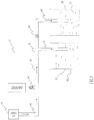
Figure 1 depicts an exemplary ventilator system utilizing a peak inspiratory pressure control duct immersed in fluid in a first container; a positive end-expiratory pressure control duct immersed in fluid in a second container; one two-port valve located in-between the peak inspiratory pressure control duct and the positive end-expiratory pressure control duct; and the height of the column of fluid in the first container is greater than the height of the column of fluid in the second container. Based on the durations of valve open and shut times, low as well high frequency breathing support can be delivered at fixed or variable ratio of inspiratory to expiratory time. -
Figure 2 depicts an exemplary ventilator system utilizing a peak inspiratory pressure control duct immersed in fluid in a first container; a positive end-expiratory pressure control duct immersed in fluid in a second container; one two-port valve located in-between the peak inspiratory pressure control duct and the positive end-expiratory pressure control duct; one high pressure safety duct immersed in fluid in the first container at a depth greater than the immersed length of the peak inspiratory pressure control duct; and the height of the column of fluid in the first container is greater than the height of the column of fluid in the second container. -
Figure 3 depicts a ventilator system as shown inFigure 1 with angled portions added to the peak inspiratory pressure control duct and the positive end-expiratory pressure control duct. -
Figure 4 depicts a ventilator system as shown inFigure 2 with angled portions added to the peak inspiratory pressure control duct and the positive end-expiratory pressure control duct and one high pressure safety duct immersed in fluid in the first container at a depth greater than the immersed length of the peak inspiratory pressure control duct. -
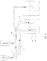
Figure 5 depicts a ventilator system of the invention utilizing a peak inspiratory pressure control duct immersed in fluid in a first container; a positive end-expiratory pressure control duct immersed in fluid in a second container; one three-port valve connected to the peak inspiratory pressure control duct, the positive end-expiratory pressure control duct and a primary duct; and the height of the column of fluid in the first container is greater than the height of the column of fluid in the second container. -
Figure 6 depicts a ventilator system of the invention utilizing a peak inspiratory pressure control duct immersed in fluid in a first container; a positive end-expiratory pressure control duct immersed in fluid in a second container; one three-port valve connected to the peak inspiratory pressure control duct, the positive end-expiratory pressure control duct and a primary duct; one high pressure safety duct immersed in fluid in the first container at a depth greater than the immersed length of the peak inspiratory pressure control duct; and the height of the column of fluid in the first container is greater than the height of the column of fluid in the second container. -
Figure 7 depicts a ventilator system as shown inFigure 5 with angled portions added to the peak inspiratory pressure control duct and to the positive end-expiratory pressure control duct. -
Figure 8 depicts a ventilator system as shown inFigure 6 with angled portions added to the peak inspiratory pressure control duct and to the positive end-expiratory pressure control duct and one high pressure safety duct immersed in fluid in the first container at a depth greater than the immersed length of the peak inspiratory pressure control duct. -
Figure 9 depicts an exemplary ventilator system utilizing a peak inspiratory pressure control duct immersed in fluid in a first container; a positive end-expiratory pressure control duct immersed in fluid in a second container; a first valve that is a two-port valve located in-between the peak inspiratory pressure control duct and the positive end-expiratory pressure control duct; a second valve that is an on-off shutoff valve located in-between the peak inspiratory pressure control duct and the two-port valve; one high pressure safety duct immersed in fluid in the first container at a depth greater than the immersed length of the peak inspiratory pressure control duct; and the height of the column of fluid in the first container is greater than the height of the column of fluid in the second container. -
Figure 10 depicts an exemplary ventilator system utilizing a connector to interconnect the peak inspiratory pressure control duct with the high-pressure safety duct. -
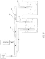
Figure 11 depicts a ventilator system of the invention utilizing a peak inspiratory pressure control duct immersed in fluid in a container; a positive end-expiratory pressure control duct immersed in fluid in the same container; one three-port valve connected to the peak inspiratory pressure control duct, the positive end-expiratory pressure control duct and a primary duct; a controller communicably connected to the valve; and immersed length of the peak inspiratory pressure control duct is greater than immersed length of the positive end-expiratory pressure control duct. -
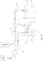
Figure 12 depicts an exemplary ventilator system utilizing a peak inspiratory pressure control duct immersed in fluid in a container; a positive end-expiratory pressure control duct immersed in fluid in the same container; one two-port valve located on the positive end-expiratory pressure control duct; one two-port valve located on the peak inspiratory pressure control duct; a controller communicably connected to both the valves; and immersed length of the peak inspiratory pressure control duct is greater than immersed length of the positive end-expiratory pressure control duct. - Embodiments described herein provide the user a device and method to set high and low pressures, oscillations, amplitude and frequency and further allows the user to set the upper limit of positive pressure that is specific for a patient to reduce the likelihood of damage to the lungs. Device parameters such as levels of fluid in the containers, lengths of the ducts immersed in the fluid in the containers can be varied to control the pressures. These embodiments also have features that allow the user to select and modulate breaths per minute, inspiratory time, and the ratio of inspiratory to expiratory time. The embodiments described herein are useful for patients of all ages including adults, children and newborn babies. Further, the embodiments can be used during transport of patients of all ages and in facilities that do not have access to mechanical ventilators. In operation, pressurized gas is released from the gas supply into the primary duct of the ventilator system disclosed in
Figures 1-12 , and the gas is delivered to a patient -
Figure 1 illustrates an exemplarypatient ventilation system 100 having apressurized gas supply 102, twocontainers primary duct 108 with two ends - theproximal end 110 and thedistal end 112. Theproximal end 110 is connected to thepressurized gas supply 102. Theduct 108 is adapted for connection to apatient interface 114 between theproximal end 110 anddistal end 112. At thedistal end 112, at least one peak inspiratory pressure (PIP)control duct 116 is connected and immersed in a body offluid 118 in thefirst container 104. At least one positive end-expiratory pressure (PEEP)control duct 120 is also connected to thedistal end 112 of the duct and immersed in the body offluid 122 in thesecond container 106. A two-port valve 124 is connected in between the inspiratory pressure control duct and the positive end-expiratory pressure control duct. Thevalve 124 cycles from open to shut position and back to open position, and the rate of cycling of the valve can be controlled by a controller (not shown) communicably connected to the valve. The failure mode of thevalve 124 is the open position whereby the gas flow is directed to the positive end expiratory pressure (PEEP)control duct 120 and the pressure at thepatient interface 114 is maintained at the lower or baseline level. - In one embodiment, the two
containers pressure control duct 116 and the positive end-expiratorypressure control duct 120 are at same vertical distance from the from the bottom inner surfaces of the twocontainers first container 104 is greater than the level of fluid in thesecond container 106 whereby immersed length which is the vertical distance measured from the top of the fluid surface to the tip of a pressure control duct is greater for the peak inspiratorypressure control duct 116 than for the positive end-expiratorypressure control duct 120. In other embodiment, the height of thecontainer 104 is greater than the height ofcontainer 106. In yet another embodiment, the level of fluid incontainer 104 is about the same as the level of fluid incontainer 106. The fluid may comprise any number of suitable fluids or liquids exhibiting a wide range of densities, masses and viscosities including but not limited to water, or water with added vinegar to reduce the likelihood of bacterial contamination of the water. - In certain embodiments, the two containers are identical in shape and size, and the ducts are pre-positioned in the containers at identical locations. The advantage of having identical containers with identically positioned PIP and PEEP control ducts is the ease of fabrication and operation. In other embodiments, the two containers are similar in shape and size and the ducts are pre-positioned in the containers at similar locations. In certain embodiments, the peak inspiratory pressure control duct and the end-expiratory pressure control duct are substantially circular having an inside diameter of between about 0.5-3 cm and the immersed length inside the containers is in the range of about 2-50 cm. The immersed vertical length of PIP and PEEP control ducts can be measured as the vertical distance from the fluid surface to the distal ends of the ducts. In all embodiments, the immersed vertical length of the PIP and PEEP control ducts can be adjusted to any value by adding or removing fluid to adjust fluid level, by sliding the ducts up and down to adjust the duct location, or doing both.
- In some embodiments of the PIP and PEEP control ducts, the diameters of the ducts are about 0.5 cm to 2 cm. In other embodiments, more than one PIP control duct and more than one PEEP control duct may be used. In yet other embodiments, the PIP and PEEP control ducts may each have substantially similar lengths and diameters or different lengths and diameters. The lengths and cross-sectional shapes of the primary duct, the PIP control duct, and the PEEP control duct are preferably short and substantially circular or slightly oval in shape. However, any or all of the ducts can have any length or cross-sectional shape including but not limited to square, rectangular, triangular etc., without departing from the spirit of the present disclosure.
- A gas supply provides pressurized medical grade gas to the ventilator system including to the primary duct, patient duct, PIP control duct and PEEP control duct. Gas delivered by the gas supply may comprise atmospheric gases or any combination, mixture, or blend of suitable gases, including but not limited to atmospheric air, oxygen, nitrogen, helium, or combinations thereof. The gas supply may comprise a gas compressor, a container of pressurized gases, a substantially portable container of pre-pressurized gases, a gas-line hookup (such as found in a hospital) or any other suitable supply of pressurized gas, or combinations thereof. The gas supply is preferably controlled or configured to have a variable gas flow rates that can be controlled by user and adjusted according to the individual requirements of each patient. The patient ventilation system or gas supply may also include one or more flow control devices (not shown) including but not limited to a mechanical valve, an electronically controlled mechanical valve, a rotameter, a pressure regulator, a flow transducer, or combinations thereof. Gas flow rates, which are commonly used in the art, typically range from about 2 liters/minute (L/min) to about 15 L/min. However, these embodiments allow any flow rates of gas set by the user. For example, larger patients may require larger gas flows. Increasing the flow rates could result in the delivery of higher pressures; however, by setting the high-pressure blow-out level of the safety duct to a safe level, one can avoid inadvertent delivery of excessively high pressures to the patient.
- A Heat and Moisture Exchanger (not shown) can also be included in the patient ventilation system to control the temperature and humidity of gas delivered to the patient interface. Continuous flow of gas in the delivery duct also prevents the patient from re-breathing gases exhaled from the lungs.
- Referring to
Figure 1 , thepatient interface 114 can be invasive or non-invasive, including but not limited to face or nasal masks, nasal prongs, nasal cannula, short tube(s) placed in the nasal or naso-paharynx, endotracheal tubes, tracheostomy tubes, or combinations thereof. The two-port valve 124 may comprise a mechanical or electromechanical valve. The two-port valve 124 may be electronically controlled or mechanically controlled such that the user is able to set the ventilation rate and inspiratory time or the ratio of inspiratory to expiratory time. The two-port valve 124 is preferably "normally open" such that in the event of failure the valve would remain open and the patient would be subjected to the lower or baseline pressure. When the two-port valve 124 is open, gases flow throughPEEP control duct 120, which is set in thecontainer 106 with lower level of fluid than thecontainer 104 having thePIP control duct 116, thereby controlling the positive end expiratory pressure in the circuit. When the two-port valve 124 is closed, gas in the pressurized circuit flows throughPIP control duct 116, which is set in acontainer 104 with higher level of fluid than thecontainer 106 having thePEEP control duct 120, thereby raising the pressure to peak inspiratory pressure and delivering a "mandatory breath" to the patient. Thevalve 124 can then be opened again to allow the patient to exhale, and the process may be repeated. In this manner, a patient can receive peak inspiratory pressure and positive end expiratory pressure (Bi-PAP ventilation) or intermittent positive pressure ventilation (IPPV). In some embodiments, any number of valves, PIP control ducts and PEEP control ducts can be used to provide different levels of high and low pressures. -
Figure 2 illustrates a ventilator system similar toFigure 1 , but has in addition, at least onesafety duct 230. Thesafety duct 230 is connected to theprimary duct 208 near theproximal end 210 of theprimary duct 208. Thesafety duct 230 is immersed in the body offluid 218 in thefirst container 204 at depth greater than the immersed length of the peak inspiratorypressure control duct 216. The safety duct allows setting the limit of a safe pressure relative to the set PIP pressure. For example, in some embodiments the fluid used is water, and the difference in vertical distance between the tip of the immersedsafety duct 230 and the immersedPIP control duct 216 can be set at 5 cm if the user wants the maximum pressure that the lungs may be subjected to be not greater than the set PIP pressure by 5 cm of water. -
Figure 3 illustrates a patient ventilator system similar to that illustrated inFigure 1 utilizing aPIP control duct 316 in thefirst container 304 and aPEEP control duct 320 in thesecond container 306. Theducts Figure 3 further comprises twoangled sections -
Figure 4 illustrates a ventilator system similar toFigure 3 , but has in addition, at least onesafety duct 430. Thesafety duct 430 is connected to theprimary duct 408 near theproximal end 410 of theprimary duct 408. Thesafety duct 430 is immersed in the body offluid 418 in thefirst container 404 at depth greater than the immersed length of the peak inspiratorypressure control duct 416. -
Figure 5 illustrates apatient ventilator system 500 of the invention having apressurized gas supply 502, twocontainers primary duct 508 with two ends -proximal end 510 anddistal end 512. Theproximal end 510 is connected to thepressurized gas supply 502. Theprimary duct 508 is adapted for connection to apatient interface 514 between theproximal end 510 anddistal end 512. A three-port (also known as three-way)valve 525 is provided with one inlet port and two outlet ports. Thedistal end 512 is connected to the inlet port of the three-port valve 525. The first outlet port of thevalve 525 is connected to at least one peak inspiratory pressure (PIP)control duct 516 that is immersed in a body offluid 518 in thefirst container 504. The second outlet port of thevalve 525 is connected to at least one positive end-expiratory pressure (PEEP)control duct 520 that is immersed in the body offluid 522 in thesecond container 506. In one embodiment, the twocontainers pressure control duct 516 and the positive end-expiratorypressure control duct 520 are at same vertical distance from the bottom inner surfaces of the twocontainers first container 504 is greater than the level of fluid in thesecond container 506 whereby immersed vertical length as measured from the top of the fluid surface to the tip of a pressure control duct is greater for the peak inspiratorypressure control duct 516 than for the positive end-expiratorypressure control duct 520. In other embodiment, the height of thecontainer 504 is greater than the height ofcontainer 506. In yet another embodiment, the level of fluid incontainer 504 is about the same as the level of fluid incontainer 506. - The
valve 525 cycles between the first outlet port and the second outlet port thereby continuously switching the flow of gas from the inlet port to the first outlet port and the inlet port to the second outlet port. Each cycle corresponds to one breath. In operation, when the gas flows from the inlet port to the first outlet port ofvalve 525, gas flows throughPIP control duct 516, which is set in thecontainer 504 with higher level of fluid than thecontainer 506 having thePEEP control duct 520, thereby controlling the PIP in the circuit. When the gas flows from the inlet port to the second outlet port ofvalve 525, gas in the pressurized circuit flows throughPEEP control duct 520, which is set in acontainer 506 with lower level of fluid than thecontainer 504 having thePIP control duct 516, thereby lowering the pressure to PEEP and allowing the patient to exhale. Thevalve 525 can then cycle back to the first outlet port to allow the patient to receive PIP, and the cycle may be repeated. In this manner, a patient can receive peak inspiratory pressure and positive end expiratory pressure (Bi-PAP ventilation) or intermittent positive pressure ventilation (IPPV). - In one embodiment, rate of cycling (measured in cycles per minute) of the
valve 525 is controlled using a controller (not shown) communicably connected to the valve. In another embodiment, controller allows user to set time T1 (Inspiratory Time) during which gas flows from the inlet port to the first outlet port and time T2 (Expiratory Time) during which gas flows from the inlet port to the second outlet port. In one embodiment, T1 is set as time in seconds. In another embodiment, T1 or T2 can be set as a fraction of cycle time or as a ratio of T1 and T2 such that the sum of T1 and T2 equals time of one cycle. Because the PIP control duct is connected to the first outlet port and the PEEP control duct is connected to the second outlet port, T1 is inspiratory time and T2 is expiratory time of a cycle or breath. In one embodiment, the expiratory time T2 is set to be greater than inspiratory time T1, and the ratio T2/T1 is greater than 1. The ratio of inspiratory time and expiratory time may be depicted as T1:T2 and the ratio shown as 1:N where, in one embodiment, N is a number greater than 1. In another embodiment, the controller does not allow the value of N to be less than 1. In another embodiment, breaths per minute (bpm) and inspiratory time (T1) in seconds are set by the user, and the controller calculates expiratory time (T2) in seconds using the formula T2 = (60/bpm) - T1. In yet another embodiment, if the calculated expiratory time (T2) in seconds is less than the inspiratory time (T1) in seconds set by the user, the controller sets T1=T2=30/bpm. In another embodiment, controller allows the user to control the ratio of inspiratory time T1 to expiratory time T2 or have T1 fixed as percent of cycle time to maintain a desired inspiration time to expiration time ratio. For example, if T1 is set as 33% of cycle time, then T2 will be 67% of cycle time, giving T1:T2 ratio of 1:2. In another embodiment, the controller is integrated with the valve, with the control logic embedded in the valve. In one embodiment, the failure mode of thevalve 525 is the open position to the second outlet port whereby the gas flow is directed to thePEEP control duct 520 and the pressure in the ventilator system is maintained at the baseline, i.e. lower level. In another embodiment, if the controller sets the cycling rate of thevalve 525 as zero, the valve remains in the open position to the second outlet port whereby the gas flow is directed to thePEEP control duct 520 and the pressure in the ventilator system is maintained at the baseline i.e. lower level. In another embodiment, if power to thevalve 525 is shut off, the valve remains in the open position to the second outlet port whereby the gas flow is directed to thePEEP control duct 520 and the pressure in the ventilator system is maintained at the baseline i.e. lower level. Thus the apparatus can be converted from Bi-PAP ventilation to bubble CPAP by simply shutting off power to the valve or setting cycling rate of the valve to zero. -
Figure 6 illustrates a ventilator system similar toFigure 5 , but has in addition, at least onesafety duct 630. Thesafety duct 630 is connected to the primary duct 608 near theproximal end 610 of the primary duct 608. Thesafety duct 630 is immersed in the body of fluid 618 in the first container 604 at depth greater than the immersed length of the peak inspiratory pressure control duct 616. The safety duct allows setting the limit of safe pressure relative to the set PIP pressure. For example, in some embodiments the fluid used is water, and the difference in vertical distance between the tip of the immersedsafety duct 630 and the immersed PIP control duct 616 can be set at 5 cm if the user wants that the maximum pressure that the lungs may be subjected to not be greater than the set PIP pressure by 5 cm of water. -
Figure 7 illustrates a patient ventilator system similar to that illustrated inFigure 5 utilizing aPIP control duct 716 in thefirst container 704 and aPEEP control duct 720 in thesecond container 706. Theducts Figure 7 further comprises twoangled sections -
Figure 8 illustrates a ventilator system similar toFigure 7 , but has in addition, at least onesafety duct 830. Thesafety duct 830 is connected to theprimary duct 808 near theproximal end 810 of theprimary duct 808. Thesafety duct 830 is immersed in the body offluid 818 in thefirst container 804 at depth greater than the immersed length of the peak inspiratorypressure control duct 816. -
Figure 9 illustrates a ventilator system similar to that inFigure 2 , but has asecond valve 926 as an additional safety. Thesecond valve 926 is provided in between the peak inspiratorypressure control duct 916 and the two-port valve 924 wherein thesecond valve 926 is an open-shut type shutoff valve that can isolate thevalve 924 and the positive end-expiratorypressure control duct 920 from the primary duct 908 and thereby from the remainder of the ventilator gas flow circuit. The isolation of thevalve 924 may be necessary if there is a catastrophic failure of thevalve 924. The shutting of theshutoff valve 926 also allows the user to employ the ventilator system as a bubble CPAP system. - In addition to the safety duct illustrated in
Figures 2 ,4 and6 , some embodiments can include additional safety features (not shown) such as a high pressure "pop-off" or "pop-open" safety valve to protect the patient from receiving airway pressures greater than a pre-determined threshold to reduce the likelihood of high pressures reaching the patient in the unlikely event that the patient circuit is occluded between the patient and the gas exiting the system through the fluid container. The pop-off valve provides a second level of protection when the safety duct such asduct 230 inFigure 2 is present in the ventilator system. The pressure level setting of pop-off valve will be generally higher than the blow-out pressure setting of the safety duct. Note however that pop-off safety valve is generally pre-set to certain values and does not provide user the flexibility provided by the safety duct, which allows setting the limit of safe pressure relative to the set PIP pressure. - In an embodiment shown in
Figure 10 , which illustrates a ventilator system similar to that inFigure 2 , thesafety duct 230 is interconnected usingconnector 233 with thePIP control duct 216 whereby the user can adjust the vertical spacing between the tip of thePIP control duct 216 and the tip of thesafety duct 230 by sliding the connector or in incremental steps of the connector, thereby providing safety of a measured fluid column height above the PIP pressure for blow out of pressurized gas in case of a pressure surge in the ventilator system. In certain embodiments, the fluid is water and the user can adjust the tip of thesafety duct 230 relative to the tip of thePIP control duct 216 such that the high pressure limit (pop off) is in the range of 0 to about 15 cm water column above the PIP pressure. In the embodiment shown inFigure 10 , the level offluid 218 incontainer 204 is about the same as the level offluid 222 incontainer 206, but the levels of fluid in the two containers could also be different as shown in the embodiments described before. In certain embodiments as shown inFigure 10 , the distal ends (tips) of the peak inspiratorypressure control duct 216 and the positive end-expiratorypressure control duct 220 are at different vertical distances from the bottom inner surfaces of the twocontainers - Some embodiments can include a low-pressure "pop-open" or one-way valve (not shown) to protect the patient from receiving airway pressures lower than a pre-determined threshold, for example sub-atmospheric pressures. In this manner, the one-way valve can help prevent a lung from collapsing, help prevent the patient from inhaling fluid, and help prevent the patient from re-breathing exhaled gases. Fresh gas of controlled concentration (not shown) can also be supplied to the one-way valve.
-
Figure 11 illustrates a patient ventilator system of the invention having apressurized gas supply 502, acontainer 505 filled with fluid, and aprimary duct 508 with two ends - theproximal end 510 and thedistal end 512. Theproximal end 510 is connected to thepressurized gas supply 502. Theprimary duct 508 is adapted for connection to apatient interface 514 between theproximal end 510 anddistal end 512. A three-port (also known as three-way)valve 525 is provided with one inlet port and two outlet ports. Thedistal end 512 is connected to the inlet port of the three-port valve 525. The first outlet port of thevalve 525 is connected to at least one peak inspiratory pressure (PIP)control duct 517 that is immersed in a body offluid 523 in thecontainer 505. The second outlet port of thevalve 525 is connected to at least one positive end-expiratory pressure (PEEP)control duct 521 that is immersed in the body offluid 523 in thecontainer 505. The immersed vertical length as measured from the top of the fluid surface to the tip of a pressure control duct is greater for thePIP control duct 517 than for thePEEP control duct 521. Thevalve 525 cycles between the first outlet port and the second outlet port thereby continuously switching the flow of gas from the inlet port to the first outlet port and the inlet port to the second outlet port. Each cycle corresponds to one breath. In one embodiment, rate of cycling (measured in cycles per minute) of thevalve 525 is controlled using acontroller 515 communicably connected to the valve. In another embodiment,controller 515 allows user to set time T1 during which gas flows from the inlet port to the first outlet port and time T2 during which gas flows from the inlet port to the second outlet port. In one embodiment, T1 is set as time in seconds. In another embodiment, T1 or T2 can be set as a fraction of cycle time or as a ratio of T1 and T2 such that the sum of T1 and T2 equals time of one cycle. Because the PIP control duct is connected to the first outlet port and the PEEP control duct is connected to the second outlet port, T1 is inspiratory time and T2 is expiratory time of a breath. In one embodiment, the expiratory time T2 is set to be greater than inspiratory time T1. In another embodiment, breaths per minute (bpm) and inspiratory time T1 in seconds are set by the user, and the controller calculates expiratory time T2 in seconds using the formula T2 = (60/bpm) - T1. In yet another embodiment, if the calculated expiratory time T2 in seconds is less than the inspiratory time T1 in seconds set by the user, thecontroller 515 sets T1=T2=30/bpm. In another embodiment,controller 515 allows user to control the ratio of inspiratory time T1 to expiratory time T2 or have T1 fixed as percent of cycle time to maintain a desired inspiration time to expiration time ratio. In another embodiment, thecontroller 515 is integrated with the valve, with the control logic embedded in the valve. In one embodiment, the failure mode of thevalve 525 is the open position to the second outlet port whereby the gas flow is directed to thePEEP control duct 520 and the pressure in the ventilator system is maintained at the baseline i.e. lower level. In another embodiment, if thecontroller 515 sets the cycling rate of thevalve 525 as zero, the valve remains in the open position to the second outlet port whereby the gas flow is directed to thePEEP control duct 520 and the pressure in the ventilator system is maintained at the baseline, i.e. lower level. In another embodiment, if power to thevalve 525 or thecontroller 515 is switched off, the valve remains in the open position to the second outlet port whereby the gas flow is directed to thePEEP control duct 520 and the pressure in the ventilator system is maintained at the baseline, i.e. lower level. -
Figure 12 illustrates an exemplary patient ventilation system having apressurized gas supply 102, acontainer 105 filled with fluid, and aprimary duct 108 with two ends - theproximal end 110 and thedistal end 112. Theproximal end 110 is connected to thepressurized gas supply 102. Theduct 108 is adapted for connection to apatient interface 114 between theproximal end 110 anddistal end 112. At thedistal end 112, at least one peak inspiratory pressure (PIP) control duct 117 is connected and immersed in a body of fluid 123 in thecontainer 105. At least one positive end-expiratory pressure (PEEP)control duct 121 is also connected to thedistal end 112 of the duct and immersed in the body of fluid 123 in thecontainer 105. The immersed length of the PIP control duct 117 is greater than the immersed length of thePEEP control duct 121. A two-port valve 109 is placed on the PIP control duct 117 and is located between the PIP control duct 117 and thedistal end 112 of the primary duct. Another two-port valve 125 is placed on thePEEP control duct 121 and is located between thePEEP control duct 121 and thedistal end 112 of the primary duct. Thevalves controller 115 communicably connected to thevalves valves controller 115 such that when thevalve 109 is open, thevalve 125 is closed and when thevalve 109 is closed, thevalve 125 is open. - In operation, when the two-
port valve 125 is open and the two-port valve 109 is closed, gases flow throughPEEP control duct 121, thereby controlling the PEEP in the circuit. When the two-port valve 125 is closed and the two-port valve 109 is open, gases in the pressurized circuit flows through PIP control duct 117, thereby raising the pressure to peak inspiratory pressure. Thevalve 125 can then be opened again andvalve 109 closed to allow the patient to exhale, and the process may be repeated. In this manner, a patient can receive peak inspiratory pressure and positive end expiratory pressure (Bi-PAP ventilation) or intermittent positive pressure ventilation (IPPV). - More examples concern methods of using one or more of the aforementioned combinations to assist the breathing of a subject (e.g., an adult, child, infant human being or another mammal). By some approaches, a subject having breathing problems is identified or selected and said subject is connected to one or more of the devices described herein. In some embodiments the subject is attached to the device by nasal prongs and in other embodiments, the subject is attached to the device by face or nasal masks, tube(s) placed in the nasopharynx, endotracheal tubes, tracheostomy tubes, or combinations thereof. Once the subject and device are connected, gas flow is initiated. Preferable gas flows for infants are about 1 to 10 L/min, whereas adults may require gas flows of about 1 to 30 L/min and large mammals may require 1 to 100 L/min or more. Optionally, the frequency, amplitude of cycling pressure, or volume of gas delivered is monitored so as to adjust the breathing assistance for the particular subject. In some embodiments, a device having a particular immersed length of the peak inspiratory pressure duct, immersed length of the positive end-expiratory pressure duct, diameter or cross-sectional area of PIP and PEEP control ducts, or particular fluid can be selected for a subject's unique needs. That is, in some examples, a patient in need of breathing assistance is selected or identified and a breathing assistance device, as described herein, is selected or identified according to a subject's age, size, or therapeutic need.
- Some examples include a method for providing continuous positive airway pressure with oscillating positive end-expiratory pressure to a subject by providing any of the devices or apparatuses described herein, releasing gas from the gas supply into the apparatus and delivering the gas to the subject. Other examples include a method for increasing the volume of gas delivered to a subject by providing any of the breathing assistance devices or apparatuses described herein, adjusting the angle of the distal end of the duct with respect to a vertical axis and releasing gas from the gas supply into the apparatus to deliver gas to the subject. In some embodiments, the distal end of the duct is adjusted to an angle greater than or equal to between about 91-170 degrees. In other embodiments, the distal end of the duct is adjusted to an angle of about 135 degrees with respect to a vertical axis.
- This example describes the ventilator system used and experiments performed to test the system described in
Figure 1 . A lung machine manufactured by Ingmar Medical, Pittsburgh, Pennsylvania (www.ingmarmed.com) was connected at patient interface of the ventilator system. A two-port (two-way) solenoid valve manufactured by MAC Valves, Inc., Wixom, Michigan (www.macvalves.com) was used in the system. The open-shut cycle of the valve was controlled using an electronic timer made by IDEC Corporation, Sunnyvale, California (us.idec.com). Compressed air and air/oxygen mixtures were used in the tests. The tubing used was the standard 10 mm tubing used with conventional ventilator systems in a hospital setting. The fluid in the containers was water at room temperature. The pressure at the patient interface was measured using a manometer manufactured by Life Design Systems, Inc., Madison, Wisconsin. The manometer had a range of -20 cm water to +80 cm water in increments of 1 cm water. Tests were run for gas flow rates from 0.5 L/min through 5 L/min in increments of 0.5 L/min, and from 5 L/min through 15 L/min in increments of 1 L/min. The gas flow rate was set using flowmeter manufactured by Precision Medical, Northampton, Pennsylvania (www.precisionmedical.com). The immersed length of the PIP control duct was varied from 10 to 30 cm of water, and the immersed length of the PEEP control duct was varied from 2 to 10 cm of water. The cycling of the valve was done from 1 cycle per minute to 60 cycles per minute. Each cycle corresponds to a breath and thus the tests were conducted from 1 breath per minute to 60 breaths per minute. - The valve offers a resistance to flow of gas, resulting in a loss of pressure. The loss of pressure due to the resistance of valve increased as the flow rate of gas was increased. At gas flow rates of 15 L/min, a pressure loss as high as 4 cm water was observed in the valve, resulting in a back pressure whereby observed PEEP at patient interface was about 4 cm of water higher than that set by the PEEP control duct in the second container. Because the PIP control duct did not have a valve in the line of flow from the patient interface to the PIP control duct, the PIP setting did not experience the back pressure from the valve. Therefore, depending on the flow rate of gas, a correction to account for the back pressure of the valve had to be made to the PEEP control duct. When the back pressure was 4 cm of water, a correction of 4 cm to the immersed length of the PEEP control duct in the second container was made such that actual immersed length was 4 cm less than the required PEEP at the patient interface. Thus if the required PEEP at the patient interface is 10 cm of water and the back pressure is 4 cm of water, then immersed length of PEEP control duct is 6 cm.
- For comparison, tests were also conducted using a single container containing water wherein both the PIP and PEEP control ducts were immersed in one and the same container, as disclosed in United States Patent No.
8,499,759 . The bubbles from one duct had an impact on observed pressure from the other duct when the PIP and PEEP control ducts were in the same container. This impact was more pronounced at higher gas flow rates and less pronounced when the diameter of the container was increased. It was found that all other conditions remaining the same, the observed pressure at the patient interface was closer to the pressure set by the control ducts when the two control ducts were in different containers (as inFigure 1 ) compared with the observed pressures when the control ducts were in the same container (as in United States Patent No.8,499,759 ). Further, it was found that, for a given gas flow rate, correction to account for back pressure in PEEP control duct is similar whether the two control ducts were placed in one container or in two separate containers. - The system in Example 1 was modified to include a safety duct as shown in
Figure 2 . The safety duct was set at a pressure 3 cm of water above the PIP pressure. The primary duct was intentionally squeezed at the distal end to simulate occlusion of the duct and the safety duct released the pressure buildup when the pressure at the patient interface reached 3 cm of water above the PIP pressure. The tests were repeated successfully at different pressure levels. - This example describes the ventilator system used and experiments performed to test the system described in
Figure 5 . A lung machine manufactured by Ingmar Medical, Pittsburgh, Pennsylvania (www.ingmarmed.com) was connected at patient interface of the ventilator system. A three-port (three-way) solenoid valve manufactured by MAC Valves, Inc., Wixom, Michigan (www.macvalves.com) was used in the system. The size of the three-port valve was the same as the two-port (two-way) valve used in Example 1. The cycling of the valve was controlled using an electronic timer made by IDEC Corporation, Sunnyvale, California (us.idec.com). Compressed air and air/oxygen mixtures were used in the tests. The tubing used was the standard 10 mm plastic tubing used with conventional ventilator systems in a hospital setting. The fluids in the containers were water at room temperature. The pressure at the patient interface was measured using a manometer manufactured by Life Design Systems, Inc., Madison, Wisconsin. The manometer had a range of -20 cm of water to +80 cm of water in increments of 1 cm water. Tests were run for gas flow rates from 0.5 L/min through 5 L/min in increments of 0.5 L/min, and from 5 L/min through 15 L/min in increments of 1 L/min. The gas flow rate was set using flowmeter manufactured by Precision Medical, Northampton, Pennsylvania (www.precisionmedical.com). The immersed length of the PIP control duct was varied from 10 to 30 cm of water, and the immersed length of the PEEP control duct was varied from 2 to 10 cm of water. The cycling of the valve was done from 1 cycle per minute to 60 cycles per minute. Each cycle corresponds to a breath and thus the tests were conducted from 1 breath per minute to 60 breaths per minute. - Similar to the back pressures observed in Example 1, at gas flow rates of 15 L/min, a back pressure as high as 4 cm. of water was observed in the valve. But unlike the performance observed for the system in
Figure 1 of Example 1 wherein the PEEP at the patient interface was affected by back pressure but the PIP at patient interface was not affected by back pressure, the three-port valve resulted in back pressure that affected similarly both PIP and PEEP as observed at the patient interface. Both the PIP control duct and the PEEP control duct had the three-port valve in the line of flow from the patient interface to respective control ducts, whereby correction to account for back pressure of the valve had to be made to both the PEEP control duct and the PIP control duct. For a given gas flow rate, the correction was similar for both the PIP control duct and the PEEP control duct. When the back pressure was 4 cm of water, a correction of 4 cm to the immersed length of the PEEP control duct was made such that actual immersed length of the PEEP control duct was 4 cm less than the required PEEP at the patient interface. And similarly a correction of 4 cm to immersed length of the PIP control duct was made such that actual immersed length of the PIP control duct was 4 cm less than the required PIP at the patient interface. Thus if the required PEEP at the patient interface is 10 cm of water, the required PIP at the patient interface is 30 cm of water, and the back pressure is 4 cm of water, then the immersed length of PEEP control duct is 6 cm and the immersed length of the PIP control duct is 26 cm. A chart was prepared that showed relationship between flow rate of gas in L/min and correction in cm. of water. - The back pressure from the valve is primarily due to size the valve (e.g., diameter of valve orifice through which gas passes, diameter of inlet and outlet passage ways and ports of valve) that creates resistance to flow of gas. The smaller the orifice size, e.g., smaller the diameter, the higher the resistance. To minimize the back pressure and the resulting correction to immersed length of PIP control duct and PEEP control duct, the size of orifice, the size of internal passage ways, the size of the ports are preferably the same as or similar to the size of the ventilator tubing. The pressure loss in the valve can be calculated using a coefficient of flow (Cv) of the valve. The calculation method is generally known. The pressure loss decreases as the Cv value increases. The gas is a compressible fluid and the Cv value and pressure loss of gas depends on temperature and pressure of the gas. The pressure of the gas in the ventilator system is slightly above atmospheric (2-50 cm of water above atmospheric) and the temperature of the gas in the ventilator system may be kept slightly above room temperature and could be as high as 40 degrees Celsius. For the gas pressure and temperature that are generally prevalent in a ventilator system, the coefficient of flow Cv of the valve is preferably greater than about 1.5 and more preferably greater than about 2.
- Tests were conducted using the valve, timer and tubing system of Example 3, but using a single container containing water wherein both the PIP control duct and the PEEP control duct were immersed in water as shown in
Figure 11 . The test parameters such as gas flow rates, immersed lengths of PIP and PEEP control ducts, cycling rates of valve were same as those in Example 3. The bubbles from one duct had an impact on observed pressure from the other duct when the PIP control duct and the PEEP control duct were in the same container. The impact was more pronounced at higher gas flow rates and less pronounced when the diameter of the container was increased. It was found that, all other conditions remaining the same, the observed pressure at the patient interface was closer to the pressure set by the control ducts when the two control ducts were in different containers compared with the observed pressures when the control ducts were in the same container. When back pressures in Example 3 were compared with back pressures in Example 4, it was found that, for a given gas flow rate, correction to account for back pressure is similar for both PIP control duct and PEEP control duct irrespective of whether the two control ducts were placed in one container or in two separate containers. - This example describes the ventilator system used and tests performed using a system as shown in
Figure 12 wherein two two-port valves were used to determine whether two two-port valves would replicate the system and tests done in Example 4 where a single three-port valve was used. Two two-port solenoid valves manufactured by MAC Valves, Inc., Wixom, Michigan were used in the system. The first two-port solenoid valve was placed on the PIP control duct and is located between the PIP control duct and the distal end of the primary duct. The second two-port solenoid valve was placed on the PEEP control duct and is located between the PEEP control duct and the distal end of the primary duct. The test parameters were the same as those in Examples 3 and 4. The two valves were controlled such that when the first valve was open, the second valve was closed and when the first valve was closed, the second valve was open. The two two-port valves were identical and their size including valve aperture and port diameters was the same as that of the three-port valve used in Example 4. The observed performance of the system in Example 5 was similar to the performance of the system in Example 4. Unlike in Example 1 where a single two-port valve is used and correction to account for back pressure was greater than zero for the PEEP control duct and zero for the PIP control duct, in Example 5 the back pressure correction was found to be greater than zero and similar for both the PIP control duct and the PEEP control duct. - There has thus been described a medically and commercially useful method and apparatus for providing breathing support. It is appreciated that though described for a patient, the method and apparatus can be used by a healthy mammal to enhance breathing. It will be appreciated that well-known structures, devices, and operations have been shown in block diagram form or without detail in order to avoid obscuring the understanding of the description. Where considered appropriate, reference numerals or terminal portions of reference numerals have been repeated among the figures to indicate corresponding or analogous elements, which may optionally have similar characteristics. The particular embodiments described are not provided to limit the invention, but to illustrate it. Further, as the following claims reflect, an inventive aspect may include a combination of embodiments described herein.
Claims (12)
- An apparatus (500) to provide breathing support to a patient comprising:a valve (525) comprising at least three ports, said three ports comprising one inlet port, a first outlet port and a second outlet port, the inlet port adapted for connection to a patient interface (514) via a primary duct (508) configured for flow of a gas;at least one peak inspiratory pressure (PIP) control duct (516, 517) connected to the first outlet port of the valve (525);at least one positive end-expiratory pressure (PEEP) control duct (520, 521) connected to the second outlet port of the valve (525);wherein the valve (525) is configured to cycle between the first outlet port and the second outlet port thereby switching flow of the gas from the inlet port to only the first outlet port and from the inlet port to only the second outlet port;wherein a cycle corresponds to one breath; wherein:the PIP control duct (516, 517) has a length immersed in a body of fluid (518, 522, 523) and the PEEP control duct (520, 521) has a length (520, 521) immersed in the body of fluid (518, 522, 523), the immersed length of PIP control duct (516, 517) being greater than the immersed length of the PEEP control duct (520, 521);the apparatus (500) is configured to direct the flow of the gas in a first sequence from a pressurized gas supply (502) to the patient interface (514), to the valve (525), through the valve (525), to the PIP control duct (516, 517), when the valve (525) switches flow of the gas from the inlet port to the first outlet port, andthe apparatus (500) is configured to direct the flow of the gas in a second sequence from the pressurized gas supply (502) to the patient interface (514), to the valve (525), through the valve (525), to the PEEP control duct (520 521), when the valve (525) switches flow of the gas from the inlet port to the second outlet port,whereby when the gas flows from the inlet port to the first outlet port of the valve (525), the gas flows through the PIP control duct (516, 517), thereby controlling PIP in the apparatus (500) so that the patient receives PIP, and when the gas flows from the inlet port to the second outlet port of the valve (525), the gas in the apparatus (500) flows through the PEEP control duct (520, 521), thereby lowering pressure in the apparatus (500) to PEEP so that the patient receives PEEP.
- The apparatus (500) of claim 1 further comprising a container (505) containing the body of fluid (523), and the PIP control duct (517) and the PEEP control duct (521) are immersed in the body of fluid (523) in the container (505).
- The apparatus (500) of claim 1 further comprising at least two containers (504, 506) wherein a first container (504) contains a first body of fluid (518) and a second container (506) contains a second body of fluid (522), and the PIP control duct (516) is immersed in the first body of fluid (518) in the first container (504) and the PEEP control duct (520) is immersed in the second body of fluid (522) in the second container (506).
- The apparatus (500) of claim 1 wherein the valve (525) has a coefficient of flow Cv greater than about 1.5.
- The apparatus (500) of claim 1 wherein the valve (525) is a solenoid valve and the fluid comprises water.
- The apparatus (700) of claim 1 wherein at least one angled section (732, 734) is connected to tip of at least one of the PIP control duct (716) and the PEEP control duct (720).
- The apparatus (500) of claim 3 wherein size and shape of the first container (504) is similar to size and shape of the second container (506) and location of tip of the PIP control duct (516) in the first container (504) is similar to location of tip of the PEEP control duct (520) in the second container (506).
- The apparatus (500) of claim 1 wherein the valve (525) is a solenoid valve and has a coefficient of flow Cv greater than about 1.5.
- The apparatus (500) of claim 1 further comprising a container (505), said container containing a first body of water (523) at room temperature wherein the PIP control duct (517) and the PEEP control duct (521) are configured to be immersed in the first body of water (523) in the container.
- The apparatus (500) of claim 1 further comprising at least two containers (504, 506) wherein a first container (504) contains a first body of water (518) at room temperature and a second container (506) contains a second body of water (522) at room temperature, and the PIP control duct (516) is immersed in the first body of water (518) in the first container (504) and the PEEP control duct (520) is immersed in the second body of water (522) in the second container (506).
- The apparatus (600) of claims 9 or 10 further comprising at least one safety duct (630) adapted for connection to the primary duct (608) and configured to be immersed in the first body of water (618), wherein immersed length of the safety duct (630) is greater than immersed length of the PIP control duct (616).
- The apparatus (500) of claim 1 further comprising at least one controller (515) communicably connected to the valve (525) to control rate of cycling of the valve (525), thereby controlling number of breaths per minute, and to control at least one of (a) inspiratory time in seconds, (b) ratio of inspiratory time to expiratory time, and (c) inspiratory time as percent of cycle time, thereby maintaining inspiration time to expiration time ratio desired by a user.
Applications Claiming Priority (4)
| Application Number | Priority Date | Filing Date | Title |
|---|---|---|---|
| US201361874323P | 2013-09-05 | 2013-09-05 | |
| US201461929947P | 2014-01-21 | 2014-01-21 | |
| US14/468,320 US9345850B2 (en) | 2013-09-05 | 2014-08-25 | Apparatus and method to provide breathing support |
| PCT/US2014/053736 WO2015034834A2 (en) | 2013-09-05 | 2014-09-02 | Apparatus to provide breathing support |
Publications (3)
| Publication Number | Publication Date |
|---|---|
| EP3041558A2 EP3041558A2 (en) | 2016-07-13 |
| EP3041558A4 EP3041558A4 (en) | 2017-04-26 |
| EP3041558B1 true EP3041558B1 (en) | 2018-06-13 |
Family
ID=52581405
Family Applications (1)
| Application Number | Title | Priority Date | Filing Date |
|---|---|---|---|
| EP14843049.9A Not-in-force EP3041558B1 (en) | 2013-09-05 | 2014-09-02 | Apparatus to provide breathing support |
Country Status (8)
| Country | Link |
|---|---|
| US (4) | US9345850B2 (en) |
| EP (1) | EP3041558B1 (en) |
| JP (1) | JP2016530022A (en) |
| CN (1) | CN105530981B (en) |
| AU (1) | AU2014315378B2 (en) |
| CA (1) | CA2923173C (en) |
| NZ (1) | NZ716171A (en) |
| WO (1) | WO2015034834A2 (en) |
Families Citing this family (10)
| Publication number | Priority date | Publication date | Assignee | Title |
|---|---|---|---|---|
| US20160235939A1 (en) * | 2013-09-05 | 2016-08-18 | Eupnea Technologies, Inc | Apparatus and method to provide breathing support |
| CN104841055B (en) * | 2015-04-21 | 2017-11-14 | 深圳市科曼医疗设备有限公司 | Control method, the device and system of lung ventilator PEEP valves |
| JP7063805B6 (en) | 2015-10-30 | 2022-06-06 | コーニンクレッカ フィリップス エヌ ヴェ | Breathing training, observation and / or assistive devices |
| CN108472464B (en) | 2015-10-30 | 2021-04-02 | 皇家飞利浦有限公司 | Respiratory training, monitoring and/or assistance device |
| WO2017189766A1 (en) * | 2016-04-26 | 2017-11-02 | Eupnea Technologies Inc. | Apparatus and method to provide breathing support |
| CN114247022A (en) * | 2016-08-31 | 2022-03-29 | 费雪派克医疗保健有限公司 | Patient interface, system and method |
| CN110464945B (en) * | 2019-08-29 | 2021-10-22 | 宁波戴维医疗器械股份有限公司 | System of high-frequency respirator, ventilation control method and device |
| US20210299396A1 (en) * | 2020-03-30 | 2021-09-30 | Gopi Mohan | Biphasic breathing ventilator |
| US11319613B2 (en) | 2020-08-18 | 2022-05-03 | Enviro Metals, LLC | Metal refinement |
| WO2023192954A2 (en) * | 2022-03-31 | 2023-10-05 | University Of Washington | Ventilation system |
Family Cites Families (39)
| Publication number | Priority date | Publication date | Assignee | Title |
|---|---|---|---|---|
| US4011866A (en) | 1965-02-05 | 1977-03-15 | Automatic Breathing Apparatus Co., Inc. | Electronically controlled pulmonary ventilator |
| US3710780A (en) | 1971-08-05 | 1973-01-16 | R Milch | Respiratory device with variable expiratory pressure resistance |
| US3811671A (en) | 1972-08-25 | 1974-05-21 | Chesebrough Ponds | Container for forced expiration exercises |
| US3977395A (en) * | 1974-02-27 | 1976-08-31 | Peter Nelson Brawn | Combination inhalation and exhalation respiratory therapy device |
| WO1981000212A1 (en) * | 1979-07-24 | 1981-02-05 | C Beyreuther | Apparatus for artificial breathing for reanimation of a new-born |
| US4471773A (en) | 1981-11-19 | 1984-09-18 | Bunnell Life System, Inc. | Apparatus and method for delivering medication to patient's respiratory system |
| US4481944A (en) | 1981-11-19 | 1984-11-13 | Bunnell Life Systems, Inc. | Apparatus and method for assisting respiration |
| EP0156409A3 (en) | 1984-02-23 | 1986-06-25 | Jean Michel Anthony | Device for moistening parts of the human body |
| US4805612A (en) | 1985-09-13 | 1989-02-21 | Sensormedics Corporation | High frequency ventilation |
| US4838259A (en) | 1986-01-27 | 1989-06-13 | Advanced Pulmonary Technologies, Inc. | Multi-frequency jet ventilation technique and apparatus |
| US4747403A (en) | 1986-01-27 | 1988-05-31 | Advanced Pulmonary Technologies, Inc. | Multi-frequency jet ventilation technique and apparatus |
| US4941469A (en) | 1987-11-12 | 1990-07-17 | Carmeli Adahan | Portable ventilator apparatus |
| GB8913085D0 (en) | 1989-06-07 | 1989-07-26 | Whitwam James G | Improvements in or relating to medical ventilators |
| GB8913084D0 (en) | 1989-06-07 | 1989-07-26 | Whitwam James G | A medical ventilator |
| ES2085515T3 (en) | 1991-05-14 | 1996-06-01 | Lugon Guillermina | DEVICE FOR RESPIRATORY EXERCISES. |
| DE4134665A1 (en) | 1991-10-19 | 1993-04-22 | Solvay Deutschland | MEDICAL INHALATION SYSTEM |
| FR2695830B1 (en) * | 1992-09-18 | 1994-12-30 | Pierre Medical Sa | Breathing aid device. |
| CH687296A5 (en) * | 1994-03-17 | 1996-11-15 | Guillermina Lugon | Respiratory exercise pumping device |
| IL114964A (en) * | 1995-08-16 | 2000-10-31 | Versamed Medical Systems Ltd | Computer controlled portable ventilator |
| EP0862474A4 (en) * | 1995-09-18 | 2000-05-03 | Resmed Ltd | Pressure control in cpap treatment or assisted respiration |
| US5632268A (en) * | 1996-02-02 | 1997-05-27 | Ellis; Donald L. | Multiple purpose fixed or portable oxygen delivery system |
| US5752506A (en) | 1996-08-21 | 1998-05-19 | Bunnell Incorporated | Ventilator system |
| WO1999016491A1 (en) | 1997-09-26 | 1999-04-08 | Airon Corporation | Pneumatically controlled multifunction medical ventilator |
| US6105572A (en) | 1997-11-07 | 2000-08-22 | Alliance Pharmaceutical Corp. | Liquid ventilator |
| US6086822A (en) * | 1998-03-02 | 2000-07-11 | Trinidad; Michael A. | Methods and apparatus for steam sterilization with reduced water consumption |
| US6805120B1 (en) | 1999-09-20 | 2004-10-19 | Fisher & Paykel Healthcare Limited | Breathing assistance apparatus |
| US6669057B2 (en) * | 2001-10-31 | 2003-12-30 | Nordson Corporation | High-speed liquid dispensing modules |
| US7478634B2 (en) | 2002-09-17 | 2009-01-20 | Jam Mohammad R | Respiratory booster machine and method for enhancing ventilation |
| DE10322964B4 (en) | 2003-05-21 | 2006-03-23 | Seleon Gmbh | Control unit for anti-snoring device and anti-snoring device |
| US7191780B2 (en) | 2003-09-22 | 2007-03-20 | Comedica Incorporated | Continuous high-frequency oscillation breathing treatment apparatus |
| US7077154B2 (en) | 2003-10-01 | 2006-07-18 | Jacobs Harris C | Apparatus for controlling the pressure of gas by bubbling through a liquid, such as bubble CPAP |
| JP2007537833A (en) | 2004-05-20 | 2007-12-27 | ディスカバリー ラボラトリーズ,インコーポレイテッド | Method, system and apparatus for non-invasive lung inhalation |
| US20070221221A1 (en) * | 2006-02-23 | 2007-09-27 | Cooke Richard H | Ventilator for Rapid Response to Respiratory Disease Conditions |
| US7387079B2 (en) * | 2006-03-23 | 2008-06-17 | Honda Motor Co., Ltd. | Automatic horn shutter |
| US8235042B2 (en) | 2007-08-31 | 2012-08-07 | Wet Nose Technologies, Llc | Exhalatory pressure device and system thereof |
| CA2720976C (en) * | 2008-04-10 | 2020-03-31 | Robert M. Diblasi | Broad-band, low frequency, high-amplitude, long time duration, oscillating airway pressure breathing apparatus and method utilizing bubbles |
| CN201320338Y (en) * | 2008-12-26 | 2009-10-07 | 王玉兰 | First-aid oxygen inhaling device |
| US8920301B2 (en) * | 2009-09-11 | 2014-12-30 | Pontificia Universidad Catolica Del Peru | Full neonatal critical care equipment |
| CN102971036B (en) * | 2010-07-02 | 2016-04-20 | 皇家飞利浦电子股份有限公司 | For performing the system of breathing diagnosis |
-
2014
- 2014-08-25 US US14/468,320 patent/US9345850B2/en active Active
- 2014-09-02 JP JP2016540317A patent/JP2016530022A/en active Pending
- 2014-09-02 CN CN201480048311.3A patent/CN105530981B/en not_active Expired - Fee Related
- 2014-09-02 EP EP14843049.9A patent/EP3041558B1/en not_active Not-in-force
- 2014-09-02 AU AU2014315378A patent/AU2014315378B2/en active Active
- 2014-09-02 WO PCT/US2014/053736 patent/WO2015034834A2/en active Application Filing
- 2014-09-02 CA CA2923173A patent/CA2923173C/en active Active
- 2014-09-02 NZ NZ716171A patent/NZ716171A/en not_active IP Right Cessation
-
2016
- 2016-04-11 US US15/095,404 patent/US10518055B2/en active Active
- 2016-04-14 US US15/098,327 patent/US9468731B2/en active Active
-
2019
- 2019-11-20 US US16/690,089 patent/US11311693B2/en active Active
Non-Patent Citations (1)
| Title |
|---|
| None * |
Also Published As
| Publication number | Publication date |
|---|---|
| EP3041558A2 (en) | 2016-07-13 |
| US11311693B2 (en) | 2022-04-26 |
| AU2014315378B2 (en) | 2018-03-29 |
| US20160220776A1 (en) | 2016-08-04 |
| AU2014315378A1 (en) | 2016-02-11 |
| US9468731B2 (en) | 2016-10-18 |
| CN105530981B (en) | 2018-01-23 |
| WO2015034834A2 (en) | 2015-03-12 |
| US10518055B2 (en) | 2019-12-31 |
| US20160220779A1 (en) | 2016-08-04 |
| WO2015034834A3 (en) | 2015-04-23 |
| CN105530981A (en) | 2016-04-27 |
| NZ716171A (en) | 2020-08-28 |
| CA2923173C (en) | 2021-06-15 |
| EP3041558A4 (en) | 2017-04-26 |
| US9345850B2 (en) | 2016-05-24 |
| CA2923173A1 (en) | 2015-03-12 |
| US20150059757A1 (en) | 2015-03-05 |
| JP2016530022A (en) | 2016-09-29 |
| US20200086072A1 (en) | 2020-03-19 |
Similar Documents
| Publication | Publication Date | Title |
|---|---|---|
| US11311693B2 (en) | Apparatus and method to provide breathing support | |
| US11123514B2 (en) | Apparatus and method to provide breathing support | |
| EP2303373B1 (en) | Broad-band, low frequency, high-amplitude, long time duration, oscillating airway pressure breathing apparatus utilizing bubbles | |
| JP2022166020A (en) | pressure regulating valve | |
| US20120017904A1 (en) | Breathing treatment system and method | |
| EP2673033B1 (en) | System and device for neonatal resuscitation and initial respiratory support | |
| BR212016024092Y1 (en) | DEVICE TO BE USED AS INSTRUMENTAL PULMONARY RE-EXPANSION TECHNIQUE | |
| WO2017189766A1 (en) | Apparatus and method to provide breathing support | |
| US20230143691A1 (en) | Device and system for respiratory support | |
| CN113842528B (en) | Differential pressure controlled high flow ventilation method and system | |
| US20230146208A1 (en) | Device and system for respiratory support | |
| CHAKRABARTI et al. | A new infant ventilator for normal and high-frequency ventilation: Influence of tracheal tube on distal airway pressure during high-frequency ventilation | |
| CN117529347A (en) | Device and system for PPV therapy and CPAP therapy |
Legal Events
| Date | Code | Title | Description |
|---|---|---|---|
| PUAI | Public reference made under article 153(3) epc to a published international application that has entered the european phase |
Free format text: ORIGINAL CODE: 0009012 |
|
| 17P | Request for examination filed |
Effective date: 20160405 |
|
| AK | Designated contracting states |
Kind code of ref document: A2 Designated state(s): AL AT BE BG CH CY CZ DE DK EE ES FI FR GB GR HR HU IE IS IT LI LT LU LV MC MK MT NL NO PL PT RO RS SE SI SK SM TR |
|
| AX | Request for extension of the european patent |
Extension state: BA ME |
|
| RAP1 | Party data changed (applicant data changed or rights of an application transferred) |
Owner name: EUPNEA TECHNOLOGIES, INC |
|
| DAX | Request for extension of the european patent (deleted) | ||
| A4 | Supplementary search report drawn up and despatched |
Effective date: 20170327 |
|
| RIC1 | Information provided on ipc code assigned before grant |
Ipc: A61M 16/20 20060101ALI20170321BHEP Ipc: A61M 16/00 20060101AFI20170321BHEP |
|
| GRAP | Despatch of communication of intention to grant a patent |
Free format text: ORIGINAL CODE: EPIDOSNIGR1 |
|
| INTG | Intention to grant announced |
Effective date: 20171219 |
|
| RAP1 | Party data changed (applicant data changed or rights of an application transferred) |
Owner name: EUPNEA TECHNOLOGIES, INC. |
|
| GRAS | Grant fee paid |
Free format text: ORIGINAL CODE: EPIDOSNIGR3 |
|
| GRAA | (expected) grant |
Free format text: ORIGINAL CODE: 0009210 |
|
| AK | Designated contracting states |
Kind code of ref document: B1 Designated state(s): AL AT BE BG CH CY CZ DE DK EE ES FI FR GB GR HR HU IE IS IT LI LT LU LV MC MK MT NL NO PL PT RO RS SE SI SK SM TR |
|
| REG | Reference to a national code |
Ref country code: GB Ref legal event code: FG4D |
|
| REG | Reference to a national code |
Ref country code: CH Ref legal event code: EP Ref country code: AT Ref legal event code: REF Ref document number: 1007829 Country of ref document: AT Kind code of ref document: T Effective date: 20180615 |
|
| REG | Reference to a national code |
Ref country code: DE Ref legal event code: R096 Ref document number: 602014027134 Country of ref document: DE |
|
| REG | Reference to a national code |
Ref country code: IE Ref legal event code: FG4D |
|
| REG | Reference to a national code |
Ref country code: FR Ref legal event code: PLFP Year of fee payment: 5 |
|
| REG | Reference to a national code |
Ref country code: NL Ref legal event code: MP Effective date: 20180613 |
|
| REG | Reference to a national code |
Ref country code: LT Ref legal event code: MG4D |
|
| PG25 | Lapsed in a contracting state [announced via postgrant information from national office to epo] |
Ref country code: SE Free format text: LAPSE BECAUSE OF FAILURE TO SUBMIT A TRANSLATION OF THE DESCRIPTION OR TO PAY THE FEE WITHIN THE PRESCRIBED TIME-LIMIT Effective date: 20180613 Ref country code: LT Free format text: LAPSE BECAUSE OF FAILURE TO SUBMIT A TRANSLATION OF THE DESCRIPTION OR TO PAY THE FEE WITHIN THE PRESCRIBED TIME-LIMIT Effective date: 20180613 Ref country code: ES Free format text: LAPSE BECAUSE OF FAILURE TO SUBMIT A TRANSLATION OF THE DESCRIPTION OR TO PAY THE FEE WITHIN THE PRESCRIBED TIME-LIMIT Effective date: 20180613 Ref country code: NO Free format text: LAPSE BECAUSE OF FAILURE TO SUBMIT A TRANSLATION OF THE DESCRIPTION OR TO PAY THE FEE WITHIN THE PRESCRIBED TIME-LIMIT Effective date: 20180913 Ref country code: BG Free format text: LAPSE BECAUSE OF FAILURE TO SUBMIT A TRANSLATION OF THE DESCRIPTION OR TO PAY THE FEE WITHIN THE PRESCRIBED TIME-LIMIT Effective date: 20180913 Ref country code: FI Free format text: LAPSE BECAUSE OF FAILURE TO SUBMIT A TRANSLATION OF THE DESCRIPTION OR TO PAY THE FEE WITHIN THE PRESCRIBED TIME-LIMIT Effective date: 20180613 Ref country code: CY Free format text: LAPSE BECAUSE OF FAILURE TO SUBMIT A TRANSLATION OF THE DESCRIPTION OR TO PAY THE FEE WITHIN THE PRESCRIBED TIME-LIMIT Effective date: 20180613 |
|
| PGFP | Annual fee paid to national office [announced via postgrant information from national office to epo] |
Ref country code: CZ Payment date: 20181026 Year of fee payment: 14 |
|
| PG25 | Lapsed in a contracting state [announced via postgrant information from national office to epo] |
Ref country code: RS Free format text: LAPSE BECAUSE OF FAILURE TO SUBMIT A TRANSLATION OF THE DESCRIPTION OR TO PAY THE FEE WITHIN THE PRESCRIBED TIME-LIMIT Effective date: 20180613 Ref country code: LV Free format text: LAPSE BECAUSE OF FAILURE TO SUBMIT A TRANSLATION OF THE DESCRIPTION OR TO PAY THE FEE WITHIN THE PRESCRIBED TIME-LIMIT Effective date: 20180613 Ref country code: HR Free format text: LAPSE BECAUSE OF FAILURE TO SUBMIT A TRANSLATION OF THE DESCRIPTION OR TO PAY THE FEE WITHIN THE PRESCRIBED TIME-LIMIT Effective date: 20180613 Ref country code: GR Free format text: LAPSE BECAUSE OF FAILURE TO SUBMIT A TRANSLATION OF THE DESCRIPTION OR TO PAY THE FEE WITHIN THE PRESCRIBED TIME-LIMIT Effective date: 20180914 |
|
| REG | Reference to a national code |
Ref country code: AT Ref legal event code: MK05 Ref document number: 1007829 Country of ref document: AT Kind code of ref document: T Effective date: 20180613 |
|
| PG25 | Lapsed in a contracting state [announced via postgrant information from national office to epo] |
Ref country code: NL Free format text: LAPSE BECAUSE OF FAILURE TO SUBMIT A TRANSLATION OF THE DESCRIPTION OR TO PAY THE FEE WITHIN THE PRESCRIBED TIME-LIMIT Effective date: 20180613 |
|
| PG25 | Lapsed in a contracting state [announced via postgrant information from national office to epo] |
Ref country code: AT Free format text: LAPSE BECAUSE OF FAILURE TO SUBMIT A TRANSLATION OF THE DESCRIPTION OR TO PAY THE FEE WITHIN THE PRESCRIBED TIME-LIMIT Effective date: 20180613 Ref country code: IS Free format text: LAPSE BECAUSE OF FAILURE TO SUBMIT A TRANSLATION OF THE DESCRIPTION OR TO PAY THE FEE WITHIN THE PRESCRIBED TIME-LIMIT Effective date: 20181013 Ref country code: PL Free format text: LAPSE BECAUSE OF FAILURE TO SUBMIT A TRANSLATION OF THE DESCRIPTION OR TO PAY THE FEE WITHIN THE PRESCRIBED TIME-LIMIT Effective date: 20180613 Ref country code: SK Free format text: LAPSE BECAUSE OF FAILURE TO SUBMIT A TRANSLATION OF THE DESCRIPTION OR TO PAY THE FEE WITHIN THE PRESCRIBED TIME-LIMIT Effective date: 20180613 Ref country code: EE Free format text: LAPSE BECAUSE OF FAILURE TO SUBMIT A TRANSLATION OF THE DESCRIPTION OR TO PAY THE FEE WITHIN THE PRESCRIBED TIME-LIMIT Effective date: 20180613 Ref country code: CZ Free format text: LAPSE BECAUSE OF FAILURE TO SUBMIT A TRANSLATION OF THE DESCRIPTION OR TO PAY THE FEE WITHIN THE PRESCRIBED TIME-LIMIT Effective date: 20180613 Ref country code: RO Free format text: LAPSE BECAUSE OF FAILURE TO SUBMIT A TRANSLATION OF THE DESCRIPTION OR TO PAY THE FEE WITHIN THE PRESCRIBED TIME-LIMIT Effective date: 20180613 |
|
| PG25 | Lapsed in a contracting state [announced via postgrant information from national office to epo] |
Ref country code: SM Free format text: LAPSE BECAUSE OF FAILURE TO SUBMIT A TRANSLATION OF THE DESCRIPTION OR TO PAY THE FEE WITHIN THE PRESCRIBED TIME-LIMIT Effective date: 20180613 |
|
| REG | Reference to a national code |
Ref country code: DE Ref legal event code: R097 Ref document number: 602014027134 Country of ref document: DE |
|
| PLBE | No opposition filed within time limit |
Free format text: ORIGINAL CODE: 0009261 |
|
| STAA | Information on the status of an ep patent application or granted ep patent |
Free format text: STATUS: NO OPPOSITION FILED WITHIN TIME LIMIT |
|
| PG25 | Lapsed in a contracting state [announced via postgrant information from national office to epo] |
Ref country code: MC Free format text: LAPSE BECAUSE OF FAILURE TO SUBMIT A TRANSLATION OF THE DESCRIPTION OR TO PAY THE FEE WITHIN THE PRESCRIBED TIME-LIMIT Effective date: 20180613 |
|
| REG | Reference to a national code |
Ref country code: CH Ref legal event code: PL |
|
| 26N | No opposition filed |
Effective date: 20190314 |
|
| PG25 | Lapsed in a contracting state [announced via postgrant information from national office to epo] |
Ref country code: DK Free format text: LAPSE BECAUSE OF FAILURE TO SUBMIT A TRANSLATION OF THE DESCRIPTION OR TO PAY THE FEE WITHIN THE PRESCRIBED TIME-LIMIT Effective date: 20180613 Ref country code: SI Free format text: LAPSE BECAUSE OF FAILURE TO SUBMIT A TRANSLATION OF THE DESCRIPTION OR TO PAY THE FEE WITHIN THE PRESCRIBED TIME-LIMIT Effective date: 20180613 |
|
| PG25 | Lapsed in a contracting state [announced via postgrant information from national office to epo] |
Ref country code: LU Free format text: LAPSE BECAUSE OF NON-PAYMENT OF DUE FEES Effective date: 20180902 |
|
| PG25 | Lapsed in a contracting state [announced via postgrant information from national office to epo] |
Ref country code: CH Free format text: LAPSE BECAUSE OF NON-PAYMENT OF DUE FEES Effective date: 20180930 Ref country code: LI Free format text: LAPSE BECAUSE OF NON-PAYMENT OF DUE FEES Effective date: 20180930 |
|
| PG25 | Lapsed in a contracting state [announced via postgrant information from national office to epo] |
Ref country code: AL Free format text: LAPSE BECAUSE OF FAILURE TO SUBMIT A TRANSLATION OF THE DESCRIPTION OR TO PAY THE FEE WITHIN THE PRESCRIBED TIME-LIMIT Effective date: 20180613 |
|
| PG25 | Lapsed in a contracting state [announced via postgrant information from national office to epo] |
Ref country code: MT Free format text: LAPSE BECAUSE OF NON-PAYMENT OF DUE FEES Effective date: 20180902 |
|
| PG25 | Lapsed in a contracting state [announced via postgrant information from national office to epo] |
Ref country code: TR Free format text: LAPSE BECAUSE OF FAILURE TO SUBMIT A TRANSLATION OF THE DESCRIPTION OR TO PAY THE FEE WITHIN THE PRESCRIBED TIME-LIMIT Effective date: 20180613 |
|
| PG25 | Lapsed in a contracting state [announced via postgrant information from national office to epo] |
Ref country code: PT Free format text: LAPSE BECAUSE OF FAILURE TO SUBMIT A TRANSLATION OF THE DESCRIPTION OR TO PAY THE FEE WITHIN THE PRESCRIBED TIME-LIMIT Effective date: 20180613 |
|
| PG25 | Lapsed in a contracting state [announced via postgrant information from national office to epo] |
Ref country code: HU Free format text: LAPSE BECAUSE OF FAILURE TO SUBMIT A TRANSLATION OF THE DESCRIPTION OR TO PAY THE FEE WITHIN THE PRESCRIBED TIME-LIMIT; INVALID AB INITIO Effective date: 20140902 Ref country code: MK Free format text: LAPSE BECAUSE OF NON-PAYMENT OF DUE FEES Effective date: 20180613 |
|
| PG25 | Lapsed in a contracting state [announced via postgrant information from national office to epo] |
Ref country code: IE Free format text: LAPSE BECAUSE OF NON-PAYMENT OF DUE FEES Effective date: 20190902 |
|
| REG | Reference to a national code |
Ref country code: BE Ref legal event code: MM Effective date: 20190930 |
|
| PG25 | Lapsed in a contracting state [announced via postgrant information from national office to epo] |
Ref country code: BE Free format text: LAPSE BECAUSE OF NON-PAYMENT OF DUE FEES Effective date: 20190930 |
|
| PGFP | Annual fee paid to national office [announced via postgrant information from national office to epo] |
Ref country code: IT Payment date: 20210930 Year of fee payment: 8 Ref country code: FR Payment date: 20210927 Year of fee payment: 8 |
|
| PGFP | Annual fee paid to national office [announced via postgrant information from national office to epo] |
Ref country code: GB Payment date: 20210923 Year of fee payment: 8 |
|
| PGFP | Annual fee paid to national office [announced via postgrant information from national office to epo] |
Ref country code: DE Payment date: 20211006 Year of fee payment: 8 |
|
| REG | Reference to a national code |
Ref country code: DE Ref legal event code: R119 Ref document number: 602014027134 Country of ref document: DE |
|
| GBPC | Gb: european patent ceased through non-payment of renewal fee |
Effective date: 20220902 |
|
| PG25 | Lapsed in a contracting state [announced via postgrant information from national office to epo] |
Ref country code: FR Free format text: LAPSE BECAUSE OF NON-PAYMENT OF DUE FEES Effective date: 20220930 Ref country code: DE Free format text: LAPSE BECAUSE OF NON-PAYMENT OF DUE FEES Effective date: 20230401 |
|
| PG25 | Lapsed in a contracting state [announced via postgrant information from national office to epo] |
Ref country code: IT Free format text: LAPSE BECAUSE OF NON-PAYMENT OF DUE FEES Effective date: 20220902 Ref country code: GB Free format text: LAPSE BECAUSE OF NON-PAYMENT OF DUE FEES Effective date: 20220902 |