EP3599731A1 - Physikalische schichtvorrichtung und verfahren zum anpassen eines interleaver levels in einem kommunikationsnetzwerk - Google Patents
Physikalische schichtvorrichtung und verfahren zum anpassen eines interleaver levels in einem kommunikationsnetzwerk Download PDFInfo
- Publication number
- EP3599731A1 EP3599731A1 EP19187279.5A EP19187279A EP3599731A1 EP 3599731 A1 EP3599731 A1 EP 3599731A1 EP 19187279 A EP19187279 A EP 19187279A EP 3599731 A1 EP3599731 A1 EP 3599731A1
- Authority
- EP
- European Patent Office
- Prior art keywords
- interleaving
- level
- oam
- word
- fec
- Prior art date
- Legal status (The legal status is an assumption and is not a legal conclusion. Google has not performed a legal analysis and makes no representation as to the accuracy of the status listed.)
- Withdrawn
Links
- 238000004891 communication Methods 0.000 title claims abstract description 44
- 238000000034 method Methods 0.000 title claims abstract description 40
- 230000004044 response Effects 0.000 claims abstract description 28
- 238000012937 correction Methods 0.000 claims abstract description 20
- 230000005540 biological transmission Effects 0.000 claims description 24
- 230000003247 decreasing effect Effects 0.000 claims description 14
- 230000008901 benefit Effects 0.000 description 8
- 238000011156 evaluation Methods 0.000 description 6
- 230000008569 process Effects 0.000 description 5
- 238000013459 approach Methods 0.000 description 4
- 238000012545 processing Methods 0.000 description 4
- 230000008859 change Effects 0.000 description 3
- 230000001419 dependent effect Effects 0.000 description 3
- 238000005516 engineering process Methods 0.000 description 3
- 230000003287 optical effect Effects 0.000 description 3
- RYGMFSIKBFXOCR-UHFFFAOYSA-N Copper Chemical compound [Cu] RYGMFSIKBFXOCR-UHFFFAOYSA-N 0.000 description 2
- 229910052802 copper Inorganic materials 0.000 description 2
- 239000010949 copper Substances 0.000 description 2
- 230000006870 function Effects 0.000 description 2
- 230000036541 health Effects 0.000 description 2
- 239000004065 semiconductor Substances 0.000 description 2
- 230000009471 action Effects 0.000 description 1
- 230000003139 buffering effect Effects 0.000 description 1
- 238000004590 computer program Methods 0.000 description 1
- 230000008878 coupling Effects 0.000 description 1
- 238000010168 coupling process Methods 0.000 description 1
- 238000005859 coupling reaction Methods 0.000 description 1
- 238000003780 insertion Methods 0.000 description 1
- 230000037431 insertion Effects 0.000 description 1
- 238000013507 mapping Methods 0.000 description 1
- 230000008520 organization Effects 0.000 description 1
- 230000037361 pathway Effects 0.000 description 1
- 239000007787 solid Substances 0.000 description 1
- 238000012360 testing method Methods 0.000 description 1
- 238000012549 training Methods 0.000 description 1
Images




Classifications
-
- H—ELECTRICITY
- H04—ELECTRIC COMMUNICATION TECHNIQUE
- H04L—TRANSMISSION OF DIGITAL INFORMATION, e.g. TELEGRAPHIC COMMUNICATION
- H04L1/00—Arrangements for detecting or preventing errors in the information received
- H04L1/004—Arrangements for detecting or preventing errors in the information received by using forward error control
- H04L1/0056—Systems characterized by the type of code used
- H04L1/0071—Use of interleaving
-
- H—ELECTRICITY
- H04—ELECTRIC COMMUNICATION TECHNIQUE
- H04L—TRANSMISSION OF DIGITAL INFORMATION, e.g. TELEGRAPHIC COMMUNICATION
- H04L1/00—Arrangements for detecting or preventing errors in the information received
- H04L1/0001—Systems modifying transmission characteristics according to link quality, e.g. power backoff
- H04L1/0002—Systems modifying transmission characteristics according to link quality, e.g. power backoff by adapting the transmission rate
-
- H—ELECTRICITY
- H04—ELECTRIC COMMUNICATION TECHNIQUE
- H04L—TRANSMISSION OF DIGITAL INFORMATION, e.g. TELEGRAPHIC COMMUNICATION
- H04L1/00—Arrangements for detecting or preventing errors in the information received
- H04L1/0001—Systems modifying transmission characteristics according to link quality, e.g. power backoff
- H04L1/0009—Systems modifying transmission characteristics according to link quality, e.g. power backoff by adapting the channel coding
-
- H—ELECTRICITY
- H04—ELECTRIC COMMUNICATION TECHNIQUE
- H04L—TRANSMISSION OF DIGITAL INFORMATION, e.g. TELEGRAPHIC COMMUNICATION
- H04L1/00—Arrangements for detecting or preventing errors in the information received
- H04L1/0001—Systems modifying transmission characteristics according to link quality, e.g. power backoff
- H04L1/0023—Systems modifying transmission characteristics according to link quality, e.g. power backoff characterised by the signalling
- H04L1/0025—Transmission of mode-switching indication
-
- H—ELECTRICITY
- H04—ELECTRIC COMMUNICATION TECHNIQUE
- H04L—TRANSMISSION OF DIGITAL INFORMATION, e.g. TELEGRAPHIC COMMUNICATION
- H04L1/00—Arrangements for detecting or preventing errors in the information received
- H04L1/004—Arrangements for detecting or preventing errors in the information received by using forward error control
- H04L1/0056—Systems characterized by the type of code used
- H04L1/0057—Block codes
-
- H—ELECTRICITY
- H04—ELECTRIC COMMUNICATION TECHNIQUE
- H04L—TRANSMISSION OF DIGITAL INFORMATION, e.g. TELEGRAPHIC COMMUNICATION
- H04L1/00—Arrangements for detecting or preventing errors in the information received
- H04L1/004—Arrangements for detecting or preventing errors in the information received by using forward error control
- H04L1/0072—Error control for data other than payload data, e.g. control data
-
- H—ELECTRICITY
- H04—ELECTRIC COMMUNICATION TECHNIQUE
- H04L—TRANSMISSION OF DIGITAL INFORMATION, e.g. TELEGRAPHIC COMMUNICATION
- H04L25/00—Baseband systems
- H04L25/02—Details ; arrangements for supplying electrical power along data transmission lines
- H04L25/14—Channel dividing arrangements, i.e. in which a single bit stream is divided between several baseband channels and reassembled at the receiver
-
- H—ELECTRICITY
- H04—ELECTRIC COMMUNICATION TECHNIQUE
- H04L—TRANSMISSION OF DIGITAL INFORMATION, e.g. TELEGRAPHIC COMMUNICATION
- H04L1/00—Arrangements for detecting or preventing errors in the information received
- H04L1/004—Arrangements for detecting or preventing errors in the information received by using forward error control
- H04L1/0045—Arrangements at the receiver end
- H04L1/0046—Code rate detection or code type detection
-
- H—ELECTRICITY
- H04—ELECTRIC COMMUNICATION TECHNIQUE
- H04L—TRANSMISSION OF DIGITAL INFORMATION, e.g. TELEGRAPHIC COMMUNICATION
- H04L1/00—Arrangements for detecting or preventing errors in the information received
- H04L1/004—Arrangements for detecting or preventing errors in the information received by using forward error control
- H04L1/0075—Transmission of coding parameters to receiver
Definitions
- the invention relates to physical layer operations, for example, physical layer operations in Ethernet connections.
- Ethernet is a communications technology that has been used in the automotive industry to provide higher bandwidth than some other conventional in-vehicle network (IVN) technologies such as Controller Area Network (CAN) and FlexRay. Automotive Ethernet technology typically uses a twisted pair of copper wires as the transmission medium.
- IVN in-vehicle network
- CAN Controller Area Network
- FlexRay Automotive Ethernet technology typically uses a twisted pair of copper wires as the transmission medium.
- Ethernet communications can be affected by, for example, external low frequency short impulse interference, narrow band radio frequency (RF) interference, and decision feedback equalizer (DFE) error propagation.
- RF narrow band radio frequency
- DFE decision feedback equalizer
- FEC forward error correction
- Reed-Solomon encoding and FEC frame interleaving.
- Embodiments of a method and a device are disclosed.
- a method for performing physical layer operations in a point-to-point network involves receiving, from a link in the communications network, information in an operations, administration, and management (OAM) word, setting an interleaving level, L, in response to the information received in the OAM word, inserting an OAM word into a forward error correction (FEC) frame, the OAM word including the set interleaving level (L), and transmitting, onto the link in the communications network, the FEC frame, which includes the OAM word.
- OAM operations, administration, and management
- the method involves adjusting the interleaving level, L, in response to information received in a subsequent OAM word and transmitting another OAM word that includes the adjusted interleaving level, L, in a subsequent FEC frame.
- the FEC frame includes a bitstream from a higher network layer.
- the interleaving level, L is an integer value that indicates the number of FEC frames that are to be interleaved.
- the interleaving level, L can indicate no interleaving or interleaving of N or more frames, where N is an integer of greater than or equal to two.
- the received OAM word is extracted from a received bit stream at a physical coding sublayer receiver (PCS-RX) and wherein the transmitted OAM word is inserted into a transmitted bit stream at a physical coding sublayer transmitter (PCS-TX).
- PCS-RX physical coding sublayer receiver
- PCS-TX physical coding sublayer transmitter
- the information received in the OAM word is information related to a bit error rate (BER) at a remote node.
- BER bit error rate
- the interleaving level, L is increased in response the BER increasing.
- the interleaving level, L is decreased in response to the BER decreasing.
- the PHY device includes a physical coding sublayer transmitter (PCS-TX), a physical medium attachment transmitter (PMA-TX), a physical coding sublayer receiver (PCS-RX), a physical medium attachment receiver (PMA-RX), and forward error correction (FEC) frame interleaving level management logic, the FEC frame interleaving level management logic configured to receive, from the PCS-RX and the PMA-RX, information in an operations, administration, and management (OAM) word, set an interleaving level, L, in response to the information received in the OAM word, and communicate the set interleaving level, L, to the PCS-TX for transmission via the PMA-TX.
- PCS-TX physical coding sublayer transmitter
- PMA-TX physical medium attachment transmitter
- PMA-RX physical coding sublayer receiver
- PMA-RX physical medium attachment receiver
- FEC forward error correction
- the PHY device is configured to insert an OAM word into an FEC frame, the OAM word including the set interleaving level, L and transmit, onto the link in the communications network, the FEC frame, which includes the OAM word.
- the FEC frame interleaving level management logic is further configured to adjust the interleaving level, L, in response to information received in a subsequent OAM word and to transmit another OAM word that includes the adjusted interleaving level, L, in a subsequent FEC frame.
- the information received in the OAM word is information related to a bit error rate (BER) at a remote node.
- BER bit error rate
- the interleaving level, L is increased in response the BER increasing and wherein the interleaving level, L, is decreased in response to the BER decreasing.
- An embodiment of a method for performing physical layer operations in a communications network involves setting an interleaving level, L, at a node in the communications network, inserting an OAM word into a forward error correction (FEC) frame, the OAM word including the set interleaving level, L, and transmitting, onto a link in the communications network, the FEC frame, which includes the OAM word.
- FEC forward error correction
- the FEC frame includes a bitstream from a higher network layer.
- setting the interleaving level, L involves obtaining latency information from a latency register, and setting the interleaving level, L, in response to the latency information.
- the latency information is received at the register from a higher layer than the physical layer.
- the interleaving level, L is increased in response the latency information indicating that payload data carried in the FEC frame is less time sensitive.
- the interleaving level, L is decreased in response to the latency information indicating that payload data carried in the FEC frame is more time sensitive.
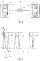
- Fig. 1 depicts a communications network 100 that connects two nodes, node A 102 and node B 104, via a physical link 106 such as an unshielded twisted pair of copper wires, e.g., 10BASE-T1L.
- the network is an in-vehicle network (IVN) that uses Ethernet at the data link layer, as specified in the Open Systems Interconnection (OSI) model as published by the International Organization for Standardization (ISO).
- Each node includes a transceiver 110 that includes a transmitter 112 and a receiver 114. Data is communicated in a channel 118 across the physical link 106.
- a channel may be a logical channel that is specified at a layer higher than the physical layer.
- a link or a communications link refers to a communications pathway that is supported by a physical link, such as twisted pair wires, and various communications protocols that are implemented at different layers in the OSI mode to achieve successful data communications between two or more nodes.
- Fig. 1 shows only two nodes in the communications network, the communications network may include more than two nodes.
- high speed Ethernet e.g., greater than 10 Mbits/s
- the techniques described herein are applicable to point-to-point and point-to-multipoint network configurations.
- Reed-Solomon encoding has been used to improve the quality of point-to-point communications across an Ethernet link.
- Various parameters can be evaluated to determine a desirable Reed-Solomon encoding scheme. Even when Reed-Solomon encoding is used, sources of interference can still degrade the performance of an in-vehicle network.
- Some sources of error include external low frequency short impulse interference that is picked up by a channel (e.g., the cable acts as an antenna and given an imbalance of cable it can produce differential short impulse signals at the input of receiver), narrow band RF interference in which a continuous time, narrow band RF signal is picked up by a channel, which converts a common mode signal to a differential signal due to cable imbalance, and decision feedback equalizer (DFE) error propagation, e.g., if a symbol is decoded incorrectly at a slicer then it may estimate a wrong value of DFE coefficients, which creates DFE error propagation.
- DFE decision feedback equalizer
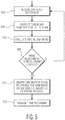
- Fig. 2 depicts short impulse signals 222, as a graph of voltage versus time, which may create interference during the transmission of bits across a link.
- the short impulse signals as shown in Fig. 2 correspond to the ISO 7637-3 capacitive coupling test (CCC).
- CCC capacitive coupling test
- U s is the maximum amplitude of the impulse signals
- ti is the 10 % pulse width
- t d is the pulse duration
- t r is the rise time
- Fig. 3A illustrates how a short impulse signal 322, or burst error, may coincide with transmission of a forward error correction (FEC) frame 326 from a transmitter 312 to a receiver 314 over a channel, where the FEC frame includes uncoded data and parity bits and may utilize Reed-Solomon encoding.
- FEC forward error correction
- the burst error coincides with FEC frame A over a significant portion of the FEC frame. If the burst error coincides with too much of the FEC frame, then the FEC frame may not be able to be recovered by the receiver.
- FEC frame interleaving has been used to improve the performance of Ethernet network communications.
- interleaving is a process that splits a frame in subsets/portions and combines and/or concatenates subsets/portions from different FEC frames to form an FEC frame that is transmitted across a link. For example a portion of FEC frame A is concatenated with a portion of FEC frame B.
- Fig. 3B also illustrates how a short impulse signal 322, or burst error, may coincide with transmission of the two interleaved FEC frames.
- the length of the Reed-Solomon codes that are used for forward error correction impacts the time required for correction and/or the complexity of the processing needed for correction.
- Interleaving can be implemented to reduce the complexity of a Reed-Solomon decoder, however, interleaving can add latency.
- FEC encoding and interleaving is implemented at the physical layer, typically by physical layer integrated circuit (IC) devices, referred to herein as "PHY chips.”
- PHY chips typically can support different combinations of FEC encoding and interleaving, with a specific combination of FEC encoding and interleaving being either pre-configured in the PHY chips in the network or negotiated between PHY chips during set up of a communications link between two nodes, e.g., during a training period.
- a method for performing physical layer operations in a communications network involves receiving, from a link in the communications network, information in an operations, administration, and management (OAM) word, setting an interleaving level, L, in response to the information received in the OAM word, inserting an OAM word into a forward error correction (FEC) frame, the OAM word including the set interleaving level, L, and transmitting, onto the link in the point-to-point network, the FEC frame, which includes the OAM word.
- OAM operations, administration, and management
- the level of interleaving can be adjusted in real-time to, for example, adapt to conditions on the link (e.g., burst errors) that may affect the BER and/or to adapt to changes in the application that is utilizing the link in the point-to-point network.
- the BER is monitored at a receiving PHY chip and communicated to a transmitting PHY chip and the level of interleaving used at the transmitting PHY chip can be adjusted in real-time in response to the BER to adapt to changes in the BER.
- the level of interleaving at the transmitting PHY chip can be increased to reduce the BER and if the BER drops below a threshold, the level of interleaving at the transmitting PHY chip can be reduced to a more efficient level, e.g., a level with reduced processing requirements, which may translate to lower latency and/or lower power consumption.
- a latency requirement is monitored at a node (e.g., through a latency register) and the level of interleaving used at the transmitting PHY chip is adjusted in real-time to adapt to changes in the latency requirement.
- a higher level layer may signal to the PHY chip that the latency requirement for an application has increased (e.g., the data is more time sensitive) and thus the level of interleaving for upcoming data transmissions across the link can be reduced or the higher level layer may signal to the PHY chip that the latency requirement for an application has decreased (e.g., the data is less time sensitive) and thus the level of interleaving for upcoming data transmissions across the link can be increased to, for example, provide a lower BER.
- Using an OAM word inserted into an FEC frame that also carries payload data to communicate changes in the level of interleaving, L, provides for an efficient way to adapt the level of interleaving in real-time (e.g., "on-the-fly") to a level of interleaving that is desirable for the current set of circumstances.
- Fig. 4A depicts an example of an FEC frame 430 (M bits) that can be used to communicate information that is used to set and/or adjust the level of interleaving in an Ethernet based in-vehicle network. As depicted in Fig.
- the FEC frame 430 includes payload bits 432 (K bits, K 1 , K 2 , K 3 ,...K i ) and OAM bits 434 (X bits, X 1 , X 2 , X 3 ,...X j ) (also referred to collectively herein as an "OAM word"), with parity bits 436 (P bits, P 1 , P 2 , P 3 ,....P M-i-j ) interspersed within the payload bits and the OAM bits.
- payload bits 432 K bits, K 1 , K 2 , K 3 ,...K i
- OAM bits 434 X bits, X 1 , X 2 , X 3 ,...X j
- parity bits 436 P bits, P 1 , P 2 , P 3 ,....P M-i-j
- the payload bits include bits of data received from a higher layer in the network stack, e.g., from the data link layer and which are intended to be communicated across the link to the same higher layer in the receiving node
- the OAM bits include bits of operations, administration, and management information that are communicated between the physical layers (e.g., between the PHY chips) in OAM words
- the parity bits are bits added to strings of binary values in the FEC frame to provide a check on the corresponding bit values in the FEC frame.
- an FEC frame is M bits, including K bits of data, X bits of OAM data, and M - K - X parity bits.
- Fig. 4B illustrates the communication of an FEC frame 430 between two nodes, node A 402 and node B 404, in an Ethernet based in-vehicle network.
- Fig. 4B depicts the layers of the OSI reference model 440 as well as an expanded view of the physical layer and the data link layer.
- the OSI reference model includes the physical layer (also referred to as layer 1), the data link layer (also referred to as layer 2), the network layer (also referred to as layer 3), the transport layer (also referred to as layer 4), the session layer (also referred to as layer 5), the presentation layer (also referred to as layer 6), and the application layer (also referred to as layer 7).
- Elements in the expanded view of the physical layer include media-dependent sublayers of the transmission medium 406, a media-dependent interface (MDI) 442, an auto-negotiation layer (AN2) 444, a physical medium attachment (PMA) 446, and the physical coding sublayer (PCS) 448, and media-independent sublayers of a media-independent interface (MII) 450, and a reconciliation layer 452.
- Elements in the expanded view of the data link layer include the media access control (MAC) layer 454, the MAC control layer (optional) 456, and the logical link control (LLC) 458, or other MAC client, layer.
- Higher layers 460 may be implemented above the data link layer.
- Fig. 5 depicts an embodiment of a method for performing physical layer operations in a point-to-point network.
- a bitstream is received at the physical level, for example, an FEC frame is received at a PHY chip of a first node from a PHY chip of a second node over an unshielded twisted pair link.
- an OAM word is extracted from the bitstream, e.g., an OAM word is extracted from an FEC frame.
- the OAM word is evaluated, for example, the OAM word may include BER information that was generated by the PHY chip at the other end of the link. In an embodiment, the BER is used to determine whether or not the level of interleaving should be adjusted.
- the level of interleaving may need to be increased to reduce the BER and if the BER is below a pre-defined threshold, the level of interleaving can be reduced, e.g., to a level with reduced processing requirements, which may translate to lower latency and/or lower power consumption.
- the level of interleaving, L it is determined whether or not to adjust the level of interleaving, L. If the level of interleaving, L, is not to be adjusted, then the process returns to block 562 and if the level of interleaving is to be adjusted, then the process proceeds to block 570.
- an OAM word is inserted into an FEC frame, the OAM word identifying the adjusted level of interleaving.
- the FEC frame is transmitted from the node on a link in the point-to-point network, the FEC frame including the OAM word with data that identifies the level of interleaving.
- the node that receives the FEC frame can then extract the OAM word and use the data that identifies the level of interleaving to set the level of interleaving for subsequent transmissions from the respective node and/or to set the level of interleaving for decoding FEC frames that are received at the node.
- the level of interleaving used between two nodes in a point-to-point Ethernet-based network can be communicated between the nodes in an OAM word of an FEC frame that also carries payload data to make real-time adjustments to the level of interleaving, for example, adjustments to the level of interleaving that are made in response to BER information that is reflective of real-time conditions on the link between the two nodes.
- Fig. 6 depicts an embodiment of a method for performing physical layer operations in a communications network.
- a latency register which includes a value that represents a desired latency or a latency requirement, is set.
- the latency register is set through a management data input/output (MDIO) interface that communicates between the physical layer and the data link layer.
- MDIO management data input/output
- an indication of a latency requirement can be signaled by other parameters.
- a latency requirement can be signaled from information that indicates the higher level application that is providing the bitstream that is to be transmitted across the link.
- the latency register may indicate a particular maximum latency level or a particular maximum latency time.
- a higher level layer may signal to the PHY chip that the latency requirement for an application has increased (e.g., less delay is acceptable) and thus the level of interleaving for upcoming data transmissions across the link can be reduced or the higher level layer may signal to the PHY chip that the latency requirement for an application has decreased (e.g., more delay is acceptable) and thus the level of interleaving for upcoming data transmissions across the link can be increased to, for example, provide a lower BER.
- the latency value stored in the latency register is evaluated. In response to the evaluation, at decision point 578, it is determined whether or not to adjust the level of interleaving, L.
- an OAM word is inserted into an FEC frame, the OAM word identifying the adjusted level of interleaving.
- the FEC frame is transmitted from the node on a link in the communications network, the FEC frame including the OAM word with data that identifies the level of interleaving.
- the node that receives the FEC frame can then extract the OAM word and use the data that identifies the level of interleaving to set the level of interleaving for subsequent transmissions from the respective node and/or to set the level of interleaving for decoding FEC frames that are received at the node.
- the level of interleaving used between two nodes in an Ethernet-based network can be communicated between the nodes in an OAM word of an FEC frame that also carries payload data to make real-time adjustments to the level of interleaving, for example, adjustments to the level of interleaving that are made in response to latency information received from a higher layer in the node, e.g., from the application layer.
- Fig. 7 illustrates the interleaving of FEC frames at the physical level between two nodes, node A 702 and node B 704, in a point-to-point network that utilizes, for example, Ethernet.
- node A transmits interleaved FEC frames on physical link 706 and node B receives interleaved FEC frames on the physical link.
- Fig. 7 illustrates the interleaving of FEC frames at the physical level between two nodes, node A 702 and node B 704, in a point-to-point network that utilizes, for example, Ethernet.
- node A transmits interleaved FEC frames on physical link 706
- node B receives interleaved FEC frames on the physical link.
- node A includes a gigabit MII (XGMII) 783, an N B /N B +1 encoder 784 (wherein N B is the number of bits in a word), a multiplexer 785, an interleaver 786, FEC frame interleaving level management logic 787, a bits-to-symbols mapper 788, and a TX-line driver (PMA-TX) 789
- node B 704 includes an RX front-end (PMA-RX) 790, a symbols-to-bits mapper 791, a deinterleaver 792, FEC frame interleaving level management logic 787, a demultiplexer 793, an N/N+1 decoder 794, and a gigabit MII (XGMII) 783.
- a bitstream is received at node A 702 (e.g., at a PHY chip) via the XGMII 783 and passed to the N B /N B +1 encoder 784 for N B /N B +1 bit encoding.
- the N B /N B +1 encoded bits are then combined with OAM bits and parity bits at the multiplexer to form FEC frames.
- OAM bits that indicate the level of interleaving and/or the BER at the node are received from the FEC frame interleaving level management logic 787 as indicated in Fig. 7 .
- Other information related to setting/adjusting the level of interleaving can also be communicated via OAM words. As shown in Fig.
- FEC frames 1, 2, 3,...N are generated and buffered in the interleaver 786.
- the frames are interleaved according to a level of interleaving that is specified by the FEC frame interleaving level management logic 787.
- an even number of FEC frames is interleaved together for convenience although it is possible to interleave an odd number of FEC frames together.
- the interleaving of N FEC frames is illustrated in Fig. 7 by the FEC frames first (from left to right) being represented horizontally and then being represented vertically such that a portion of each of the FEC frames is concatenated into a stream of bits that includes interleaved bit strings from each FEC frame.
- the interleaved frames are then mapped from bits to symbols by the bits-to-symbols mapper 788 and then converted to analog signals that are transmitted on the link 706 by the TX-line driver (PMA) 789.
- PMA TX-line driver
- the transmissions are received by the RX front-end (PMA) 790 of node B 704, which converts the analog signals to received symbols, and the received symbols are mapped to bits by the symbols-to-bits mapper 791.
- the deinterleaving of N FEC frames is illustrated in Fig. 7 by the FEC frames first (from right to left) being represented vertically and then being represented horizontally. The frames are deinterleaved according to a level of interleaving that is specified by the FEC frame interleaving level management logic 787.
- the level of deinterleaving matches the level of interleaving that was used by node A for transmission of the FEC frames, where the level of interleaving is communicated between the two nodes using OAM words inserted into the FEC frames.
- the bits that make up an FEC frame are identified by the demultiplexer 793. For example, the bits of the FEC frames are identified as payload bits, OAM bits, or parity bits.
- the payload bits are then decoded by the N B /N B +1 decoder 794.
- the decoded bits are passed to the XGMII 783, which can pass the bits to a higher layer application.
- the OAM bits e.g., in the form of an OAM word
- the FEC frame interleaving level management logic 787 as indicated in Fig. 7 .
- the OAM word may include information about BER from the other node and/or information about a level of interleaving (e.g., a value for L) from the other node.
- a level of interleaving e.g., a value for L
- Other information related to setting/adjusting the level of interleaving can also be communicated via OAM words.
- the logic for determining the level of FEC frame interleaving, L can be BER based and/or latency based.
- a BER based approach if the burst error correction requirement is higher than a current setting, then the value of interleaving level, L, is increased until the monitored BER satisfies the requirement. Otherwise, if the burst error correction requirement is lower than the current setting, then the value of the interleaving level, L, is decreased.
- the latency requirement is monitored in register. If the latency requirement (as indicated by the register value) is shorter than the current setting, then the value of the interleaving level, L, is decreased until the interleaving level satisfies the requirement.
- the value of the interleaving level, L is increased.
- Other parameters and/or criteria may be used to set the level of interleaving, L, and/or other values/information may be carried in an OAM word to communicate information that is used to set the level of interleaving, L.
- Fig. 8 depicts an example of components at the physical level of two nodes, node A 802 and node B 804, in a point-to-point communications network that are connected by a link 806.
- the physical layers are embodied as integrated circuits 895 that incorporate physical layer functionality, referred to herein as "PHY chips.”
- the PHY chips 895 may be components of the nodes A and B, respectively, and the nodes may include additional elements, such as elements of an electronic control unit (ECU) as is known in the field of in-vehicle networks.
- ECUs may also include a microprocessor, a sensor, an actuator, etc. as is known in the field.
- Fig. 8 also depicts higher level layers of the node, e.g., the data link layer (layer 2), the network layer (layer 3), and the application layer (layer 7), which may interact with the physical layer.
- the PHY chip 895 includes a transceiver 810 that includes a physical coding sublayer transmitter (PCS-TX) 851, a physical medium attachment transmitter (PMA-TX) 889, a physical coding sublayer receiver (PCS-RX) 853, a physical medium attachment receiver (PMA-RX) 890, FEC frame interleaving level management logic 887, a MII 883 (e.g., XGMII), and an MDIO 855.
- PCS-TX physical coding sublayer transmitter
- PMA-TX physical medium attachment transmitter
- PMA-RX physical coding sublayer receiver
- FEC frame interleaving level management logic 887 e.g., XGMII
- MII 883 e.g., XGMII
- the FEC interleaving level management logic 887 includes a register 857, latency evaluation logic 859, BER logic 861, level setting logic 863, an OAM-TX module 865, an OAM-RX module 867, and control logic 869.
- the physical medium attachment transmitter (PCS-TX) 851, the physical medium attachment transmitter (PMA-TX) 889, the physical coding sublayer receiver (PCS-RX) 853, and the physical medium attachment receiver (PMA-RX) 890 perform functions that include functions which are known, for example, in the field of Ethernet based in-vehicle networks.
- the register is a memory register that stores information that can be used to determine the level of interleaving that is employed by the PHY chip.
- the register 857 receives information about latency from a higher layer and/or information about BER from the BER logic 861.
- the latency evaluation logic 859 is configured to evaluate latency information to, for example, determine a desired latency for a particular bitstream.
- the level setting logic 863 is configured to set or adjust the level of interleaving based on, for example, latency information from the latency evaluation logic 859 and/or BER information from the BER logic 861.
- the level of latency that is set by the level setting logic 863 is provided to the OAM-TX module 865.
- the OAM-TX module 865 may include buffering memory and/or logic to provide OAM bits (e.g., as an OAM word) to the transceiver 810 for insertion into an FEC frame and/or to set the level of interleaving for the PCS-TX 851.
- the PCS-TX 851 is configured to perform the multiplexing, FEC frame interleaving, and bits-to-symbols mapping as described with reference to Fig. 7 .
- the FEC frames are transmitted on the link 806 as analog signals by the PMA-TX 889.
- the PMA-RX 890 of node A 802 receives electrical signals on the link 806, decodes the signals into symbols, and provides the symbols to the PCS-RX 853.
- the PCS-RX maps the symbols to a bitstream, deinterleaves the FEC frames, and demultiplexes the OAM bits and the payload bits as described with reference to Fig. 7 .
- An OAM word extracted from an FEC frame by the PCS-RX 853 is provided to the OAM-RX module 867 for evaluation.
- the data carried in the OAM word may be provided to the BER logic 861 and/or to the control logic 869.
- the OAM-RX module 867 may provide information about the BER to the BER logic 861.
- the BER logic 861 may provide information for storage in the register 857 and/or may provide information for use in setting/adjusting the level of interleaving, L.
- the level of interleaving may be provided to the control module 869, which can manage negotiation of the interleaving level between nodes and/or communicate the level of interleaving in an OAM word.
- the control module may also inform the PCS-TX 851 of the level of interleaving for transmission and inform the PCS-RX 853 of the level of interleaving for reception of the FEC frames.
- the information held in the register 857 of the FEC interleaving level management logic 887 is read only, while in other embodiments, at least some of the information can be written to the register by end users. Internal health related data or performance related data can be also stored in the register and later read by end users for certain applications.
- the OAM bits are used to pass information from a local PHY chip to a remote PHY chip.
- the OAM bits are embedded into the bitstream of data that is received from a higher layer, e.g., from the data link layer.
- the OAM bits may include information related to, for example, node health, control, managing link partners, interoperability, and interleaving.
- OAM bits are used by a node to communicate with a remote node to agree on the timing to start a new configuration, e.g., a new level of interleaving.
- OAM bits are used by a receiving node to learn the status of the physical layer (e.g., PHY chip) of a transmitting node and/or to communicate certain defined/agreed actions.
- the OAM bits can be used to communicate between two PHY chips to agree on the timing to start a new configuration, e.g., a new level of interleaving.
- an end user can set a latency requirement for the target application, which can be written into the register through the MDIO interface.
- the latency can be read from the register to determine the level of interleaving, L, for a forward error correction scheme.
- the BER logic can extract information that is related to burst error and/or the BER of a channel. The information can be shared with the register if, for example, the end users would like to read the information from the register for further processing at the application layer.
- BER information and/or burst error information can be provided to the level setting logic to identify a new level of interleaving, L.
- the level setting logic is configured to identify a value, L, using, for example, burst errors/BER and latency.
- the value of L can be provided to the OAM-TX module.
- the control module is configured to provide control related information to the OAM-TX module such that a remote PHY chip can configure its settings based on the received information, e.g., as received through and OAM word at its OAM-RX module.
- link partners i.e., nodes
- link partners agree/disagree to decrease the value of L.
- Link partners communicate through OAM bits to decrease the value of L and link partners communicate through OAM bits to increase the value of L.
- link partners agree on the timing (e.g., when) to change the level of interleaving, L, for the next session at the transmitter and the receiver of both link partners so that the transmissions can be decoded correctly.
- the receiver of a link partner receives an adjusted value of L and acknowledges through OAM bits that it is willing to increase the value of L.
- the OAM bits are used to indicate to a link partner that the number of errors is increasing or that the number of errors is decreasing.
- a single PHY chip can be used for multiple different applications without having to redesign the chip.
- the PHY chips can be produced in volume, which can result in a product cost savings.
- operation of a PHY chip as described above can save power by optimizing the level of interleaving to meet the needs to the application.
- the elements of the physical layer as shown in Figs. 7 and 8 can be integrated into an IC device that includes other functionality, such as microprocessor functionality.
- the components of a traditional PHY chip can be integrated onto a System-on-Chip (SoC).
- SoC System-on-Chip
- Embodiments of a method and a device are disclosed.
- a method for performing physical layer operations in a point-to-point network involves receiving, from a link in the communications network, information in an operations, administration, and management (OAM) word, setting an interleaving level, L, in response to the information received in the OAM word, inserting an OAM word into a forward error correction (FEC) frame, the OAM word including the set interleaving level (L), and transmitting, onto the link in the communications network, the FEC frame, which includes the OAM word.
- OAM operations, administration, and management
- an embodiment of a computer program product includes a computer useable storage medium to store a computer readable program.
- the computer-useable or computer-readable storage medium can be an electronic, magnetic, optical, electromagnetic, infrared, or semiconductor system (or apparatus or device).
- Examples of non-transitory computer-useable and computer-readable storage media include a semiconductor or solid state memory, magnetic tape, a removable computer diskette, a random access memory (RAM), a read-only memory (ROM), a rigid magnetic disk, and an optical disk.
- Current examples of optical disks include a compact disk with read only memory (CD-ROM), a compact disk with read/write (CD-R/W), and a digital video disk (DVD).
- embodiments of the invention may be implemented entirely in hardware or in an implementation containing both hardware and software elements.
- the software may include but is not limited to firmware, resident software, microcode, etc.
Landscapes
- Engineering & Computer Science (AREA)
- Computer Networks & Wireless Communication (AREA)
- Signal Processing (AREA)
- Quality & Reliability (AREA)
- Power Engineering (AREA)
- Detection And Prevention Of Errors In Transmission (AREA)
Applications Claiming Priority (1)
| Application Number | Priority Date | Filing Date | Title |
|---|---|---|---|
| US16/044,325 US10439761B1 (en) | 2018-07-24 | 2018-07-24 | Physical layer device and method for performing physical layer operations in a communications network |
Publications (1)
| Publication Number | Publication Date |
|---|---|
| EP3599731A1 true EP3599731A1 (de) | 2020-01-29 |
Family
ID=67438160
Family Applications (1)
| Application Number | Title | Priority Date | Filing Date |
|---|---|---|---|
| EP19187279.5A Withdrawn EP3599731A1 (de) | 2018-07-24 | 2019-07-19 | Physikalische schichtvorrichtung und verfahren zum anpassen eines interleaver levels in einem kommunikationsnetzwerk |
Country Status (2)
| Country | Link |
|---|---|
| US (1) | US10439761B1 (de) |
| EP (1) | EP3599731A1 (de) |
Families Citing this family (4)
| Publication number | Priority date | Publication date | Assignee | Title |
|---|---|---|---|---|
| CN110875796B (zh) * | 2018-08-30 | 2021-02-23 | 华为技术有限公司 | 物理层端口通道化的方法和装置 |
| US12580814B2 (en) * | 2022-12-22 | 2026-03-17 | Nvidia Corporation | Adapting forward error correction (FEC) or link parameters for improved post-FEC performance |
| US12267210B2 (en) * | 2022-12-22 | 2025-04-01 | Nvidia Corporation | Adapting forward error correction (FEC) or link parameters for improved post-FEC performance |
| CN117997973B (zh) * | 2023-08-25 | 2025-03-28 | 深圳市汇顶科技股份有限公司 | 数据传输方法、芯片和存储介质 |
Citations (4)
| Publication number | Priority date | Publication date | Assignee | Title |
|---|---|---|---|---|
| US6452941B1 (en) * | 1998-09-16 | 2002-09-17 | Telefonaktiebolaget Lm Ericsson (Publ) | Method and system for alternating transmission of codec mode information |
| US20160080000A1 (en) * | 1998-04-17 | 2016-03-17 | At&T Intellectual Property I, Lp | Method and system for controlling an interleaver |
| US20160127079A1 (en) * | 2004-03-03 | 2016-05-05 | Tq Delta, Llc | Impulse noise management |
| US20160344514A1 (en) * | 2015-05-18 | 2016-11-24 | Microsoft Technology Licensing, Llc | Adjustable Interleaving for Communication Data |
Family Cites Families (8)
| Publication number | Priority date | Publication date | Assignee | Title |
|---|---|---|---|---|
| DE69527525T2 (de) * | 1995-08-21 | 2003-04-03 | Alcatel, Paris | Verfahren zur Schachtelung von Datenrahmen, Übertragungsfehlerkorrekturanordnung und Modulator damit |
| US5956338A (en) * | 1996-07-09 | 1999-09-21 | Ericsson, Inc. | Protocol for broadband data communication over a shared medium |
| US7278081B1 (en) * | 2002-06-13 | 2007-10-02 | Applied Micro Circuits Corporation | Optical transport network frame structure with in-band data channel and forward error correction |
| US6812870B1 (en) * | 2003-09-11 | 2004-11-02 | Xilinx, Inc. | Enhanced 8b/10b encoding/decoding and applications thereof |
| US7930616B2 (en) * | 2007-04-12 | 2011-04-19 | Cisco Technology, Inc. | Variable forward error correction for optical communication links |
| EP3103310B1 (de) * | 2014-02-03 | 2022-09-14 | Telefonaktiebolaget LM Ericsson (publ) | Einkapselung von digitalen nachrichtenverkehr zur übertragung über eine optische verbindung |
| US9628340B2 (en) * | 2014-05-05 | 2017-04-18 | Ciena Corporation | Proactive operations, administration, and maintenance systems and methods in networks using data analytics |
| EP3340552B1 (de) | 2016-12-22 | 2020-03-18 | Nxp B.V. | Phy-sende-empfänger mit adaptivem tx-treiber und verfahren zum betrieb davon |
-
2018
- 2018-07-24 US US16/044,325 patent/US10439761B1/en active Active
-
2019
- 2019-07-19 EP EP19187279.5A patent/EP3599731A1/de not_active Withdrawn
Patent Citations (4)
| Publication number | Priority date | Publication date | Assignee | Title |
|---|---|---|---|---|
| US20160080000A1 (en) * | 1998-04-17 | 2016-03-17 | At&T Intellectual Property I, Lp | Method and system for controlling an interleaver |
| US6452941B1 (en) * | 1998-09-16 | 2002-09-17 | Telefonaktiebolaget Lm Ericsson (Publ) | Method and system for alternating transmission of codec mode information |
| US20160127079A1 (en) * | 2004-03-03 | 2016-05-05 | Tq Delta, Llc | Impulse noise management |
| US20160344514A1 (en) * | 2015-05-18 | 2016-11-24 | Microsoft Technology Licensing, Llc | Adjustable Interleaving for Communication Data |
Also Published As
| Publication number | Publication date |
|---|---|
| US10439761B1 (en) | 2019-10-08 |
Similar Documents
| Publication | Publication Date | Title |
|---|---|---|
| US10700810B2 (en) | Physical layer device and method for performing physical layer operations in a communications network | |
| EP3599731A1 (de) | Physikalische schichtvorrichtung und verfahren zum anpassen eines interleaver levels in einem kommunikationsnetzwerk | |
| US7920597B2 (en) | Method and system for low power idle signal transmission in ethernet networks | |
| CN100576785C (zh) | 以太网中的前向纠错编码 | |
| US7602806B2 (en) | Signaling and coding methods and apparatus for long-range 10 and 100 MBPS ethernet transmission | |
| CN112564851B (zh) | 以太网链路速率切换的方法、装置及计算机可读存储介质 | |
| US20200072889A1 (en) | Physical layer device and method for performing physical layer operations in a communications network | |
| US8233507B1 (en) | 8/10 and 64/66 aggregation | |
| CN113169918B (zh) | 用于串行总线系统的用户站的装置和用于串行总线系统中的通信的方法 | |
| KR20100116645A (ko) | 등화 파라미터 적응 방법, 로컬 송수신기 및 트레이닝 프레임 추출기 | |
| KR20160039651A (ko) | 버스 시스템용 가입자국, 그리고 버스 시스템의 가입자국의 오류 허용범위 개선 방법 | |
| CN109274392B (zh) | 用于执行串行器-并行器通信的网络装置 | |
| US7823041B2 (en) | Techniques for decoding information from signals received over multiple channels | |
| US11206174B2 (en) | Method and system for diagnosis of failures in a communications network | |
| CN114846762A (zh) | 通信链路初始化方法及装置 | |
| CN109257142B (zh) | 用于执行连续或周期性链路训练的系统、设备和方法 | |
| US10567179B1 (en) | Network device and method for performing network operations in a communications network | |
| US7447168B2 (en) | System and method for auto-negotiation in a data communication device | |
| CN114342325B (zh) | 用于串行总线系统的用户站和用于在串行总线系统中进行通信的方法 | |
| KR102909545B1 (ko) | 직렬 버스 시스템용 가입자국 및 직렬 버스 시스템에서의 통신 방법 | |
| US10615992B2 (en) | Network device and method for performing network operations in a communications network | |
| JP7564365B2 (ja) | シリアルバスシステム用の加入者局およびシリアルバスシステムでの通信方法 | |
| US20250132949A1 (en) | Transmitting/receiving device for selectively waking up a subscriber station of a serial bus system and method for selectively waking up a subscriber station in a serial bus system | |
| US20260025292A1 (en) | Transmitting/receiving device for a subscriber station of a serial bus system, and method for communicating by means of differential signals in a serial bus system | |
| CN115280726B (zh) | 发送/接收装置和通信控制装置以及通信方法 |
Legal Events
| Date | Code | Title | Description |
|---|---|---|---|
| PUAI | Public reference made under article 153(3) epc to a published international application that has entered the european phase |
Free format text: ORIGINAL CODE: 0009012 |
|
| STAA | Information on the status of an ep patent application or granted ep patent |
Free format text: STATUS: THE APPLICATION HAS BEEN PUBLISHED |
|
| AK | Designated contracting states |
Kind code of ref document: A1 Designated state(s): AL AT BE BG CH CY CZ DE DK EE ES FI FR GB GR HR HU IE IS IT LI LT LU LV MC MK MT NL NO PL PT RO RS SE SI SK SM TR |
|
| AX | Request for extension of the european patent |
Extension state: BA ME |
|
| STAA | Information on the status of an ep patent application or granted ep patent |
Free format text: STATUS: REQUEST FOR EXAMINATION WAS MADE |
|
| 17P | Request for examination filed |
Effective date: 20200729 |
|
| RBV | Designated contracting states (corrected) |
Designated state(s): AL AT BE BG CH CY CZ DE DK EE ES FI FR GB GR HR HU IE IS IT LI LT LU LV MC MK MT NL NO PL PT RO RS SE SI SK SM TR |
|
| STAA | Information on the status of an ep patent application or granted ep patent |
Free format text: STATUS: EXAMINATION IS IN PROGRESS |
|
| 17Q | First examination report despatched |
Effective date: 20211112 |
|
| STAA | Information on the status of an ep patent application or granted ep patent |
Free format text: STATUS: THE APPLICATION HAS BEEN WITHDRAWN |
|
| 18W | Application withdrawn |
Effective date: 20231010 |