EP3599708A1 - Inverter based apparatus and control method thereof - Google Patents
Inverter based apparatus and control method thereof Download PDFInfo
- Publication number
- EP3599708A1 EP3599708A1 EP18185870.5A EP18185870A EP3599708A1 EP 3599708 A1 EP3599708 A1 EP 3599708A1 EP 18185870 A EP18185870 A EP 18185870A EP 3599708 A1 EP3599708 A1 EP 3599708A1
- Authority
- EP
- European Patent Office
- Prior art keywords
- current
- inverter
- voltage
- active
- capacitor
- Prior art date
- Legal status (The legal status is an assumption and is not a legal conclusion. Google has not performed a legal analysis and makes no representation as to the accuracy of the status listed.)
- Withdrawn
Links
Images

Classifications
-
- H—ELECTRICITY
- H02—GENERATION; CONVERSION OR DISTRIBUTION OF ELECTRIC POWER
- H02M—APPARATUS FOR CONVERSION BETWEEN AC AND AC, BETWEEN AC AND DC, OR BETWEEN DC AND DC, AND FOR USE WITH MAINS OR SIMILAR POWER SUPPLY SYSTEMS; CONVERSION OF DC OR AC INPUT POWER INTO SURGE OUTPUT POWER; CONTROL OR REGULATION THEREOF
- H02M1/00—Details of apparatus for conversion
- H02M1/32—Means for protecting converters other than automatic disconnection
-
- H—ELECTRICITY
- H02—GENERATION; CONVERSION OR DISTRIBUTION OF ELECTRIC POWER
- H02P—CONTROL OR REGULATION OF ELECTRIC MOTORS, ELECTRIC GENERATORS OR DYNAMO-ELECTRIC CONVERTERS; CONTROLLING TRANSFORMERS, REACTORS OR CHOKE COILS
- H02P27/00—Arrangements or methods for the control of AC motors characterised by the kind of supply voltage
- H02P27/04—Arrangements or methods for the control of AC motors characterised by the kind of supply voltage using variable-frequency supply voltage, e.g. inverter or converter supply voltage
- H02P27/06—Arrangements or methods for the control of AC motors characterised by the kind of supply voltage using variable-frequency supply voltage, e.g. inverter or converter supply voltage using dc to ac converters or inverters
- H02P27/08—Arrangements or methods for the control of AC motors characterised by the kind of supply voltage using variable-frequency supply voltage, e.g. inverter or converter supply voltage using dc to ac converters or inverters with pulse width modulation
-
- D—TEXTILES; PAPER
- D06—TREATMENT OF TEXTILES OR THE LIKE; LAUNDERING; FLEXIBLE MATERIALS NOT OTHERWISE PROVIDED FOR
- D06F—LAUNDERING, DRYING, IRONING, PRESSING OR FOLDING TEXTILE ARTICLES
- D06F23/00—Washing machines with receptacles, e.g. perforated, having a rotary movement, e.g. oscillatory movement, the receptacle serving both for washing and for centrifugally separating water from the laundry
- D06F23/02—Washing machines with receptacles, e.g. perforated, having a rotary movement, e.g. oscillatory movement, the receptacle serving both for washing and for centrifugally separating water from the laundry and rotating or oscillating about a horizontal axis
-
- D—TEXTILES; PAPER
- D06—TREATMENT OF TEXTILES OR THE LIKE; LAUNDERING; FLEXIBLE MATERIALS NOT OTHERWISE PROVIDED FOR
- D06F—LAUNDERING, DRYING, IRONING, PRESSING OR FOLDING TEXTILE ARTICLES
- D06F34/00—Details of control systems for washing machines, washer-dryers or laundry dryers
- D06F34/10—Power supply arrangements, e.g. stand-by circuits
-
- D—TEXTILES; PAPER
- D06—TREATMENT OF TEXTILES OR THE LIKE; LAUNDERING; FLEXIBLE MATERIALS NOT OTHERWISE PROVIDED FOR
- D06F—LAUNDERING, DRYING, IRONING, PRESSING OR FOLDING TEXTILE ARTICLES
- D06F37/00—Details specific to washing machines covered by groups D06F21/00 - D06F25/00
- D06F37/30—Driving arrangements
- D06F37/304—Arrangements or adaptations of electric motors
-
- H—ELECTRICITY
- H02—GENERATION; CONVERSION OR DISTRIBUTION OF ELECTRIC POWER
- H02M—APPARATUS FOR CONVERSION BETWEEN AC AND AC, BETWEEN AC AND DC, OR BETWEEN DC AND DC, AND FOR USE WITH MAINS OR SIMILAR POWER SUPPLY SYSTEMS; CONVERSION OF DC OR AC INPUT POWER INTO SURGE OUTPUT POWER; CONTROL OR REGULATION THEREOF
- H02M5/00—Conversion of ac power input into ac power output, e.g. for change of voltage, for change of frequency, for change of number of phases
- H02M5/40—Conversion of ac power input into ac power output, e.g. for change of voltage, for change of frequency, for change of number of phases with intermediate conversion into dc
- H02M5/42—Conversion of ac power input into ac power output, e.g. for change of voltage, for change of frequency, for change of number of phases with intermediate conversion into dc by static converters
- H02M5/44—Conversion of ac power input into ac power output, e.g. for change of voltage, for change of frequency, for change of number of phases with intermediate conversion into dc by static converters using discharge tubes or semiconductor devices to convert the intermediate dc into ac
- H02M5/453—Conversion of ac power input into ac power output, e.g. for change of voltage, for change of frequency, for change of number of phases with intermediate conversion into dc by static converters using discharge tubes or semiconductor devices to convert the intermediate dc into ac using devices of a triode or transistor type requiring continuous application of a control signal
- H02M5/458—Conversion of ac power input into ac power output, e.g. for change of voltage, for change of frequency, for change of number of phases with intermediate conversion into dc by static converters using discharge tubes or semiconductor devices to convert the intermediate dc into ac using devices of a triode or transistor type requiring continuous application of a control signal using semiconductor devices only
-
- H—ELECTRICITY
- H02—GENERATION; CONVERSION OR DISTRIBUTION OF ELECTRIC POWER
- H02P—CONTROL OR REGULATION OF ELECTRIC MOTORS, ELECTRIC GENERATORS OR DYNAMO-ELECTRIC CONVERTERS; CONTROLLING TRANSFORMERS, REACTORS OR CHOKE COILS
- H02P21/00—Arrangements or methods for the control of electric machines by vector control, e.g. by control of field orientation
- H02P21/14—Estimation or adaptation of machine parameters, e.g. flux, current or voltage
-
- H—ELECTRICITY
- H02—GENERATION; CONVERSION OR DISTRIBUTION OF ELECTRIC POWER
- H02P—CONTROL OR REGULATION OF ELECTRIC MOTORS, ELECTRIC GENERATORS OR DYNAMO-ELECTRIC CONVERTERS; CONTROLLING TRANSFORMERS, REACTORS OR CHOKE COILS
- H02P21/00—Arrangements or methods for the control of electric machines by vector control, e.g. by control of field orientation
- H02P21/22—Current control, e.g. using a current control loop
-
- H—ELECTRICITY
- H02—GENERATION; CONVERSION OR DISTRIBUTION OF ELECTRIC POWER
- H02P—CONTROL OR REGULATION OF ELECTRIC MOTORS, ELECTRIC GENERATORS OR DYNAMO-ELECTRIC CONVERTERS; CONTROLLING TRANSFORMERS, REACTORS OR CHOKE COILS
- H02P21/00—Arrangements or methods for the control of electric machines by vector control, e.g. by control of field orientation
- H02P21/36—Arrangements for braking or slowing; Four quadrant control
-
- H—ELECTRICITY
- H02—GENERATION; CONVERSION OR DISTRIBUTION OF ELECTRIC POWER
- H02P—CONTROL OR REGULATION OF ELECTRIC MOTORS, ELECTRIC GENERATORS OR DYNAMO-ELECTRIC CONVERTERS; CONTROLLING TRANSFORMERS, REACTORS OR CHOKE COILS
- H02P3/00—Arrangements for stopping or slowing electric motors, generators, or dynamo-electric converters
- H02P3/06—Arrangements for stopping or slowing electric motors, generators, or dynamo-electric converters for stopping or slowing an individual dynamo-electric motor or dynamo-electric converter
- H02P3/18—Arrangements for stopping or slowing electric motors, generators, or dynamo-electric converters for stopping or slowing an individual dynamo-electric motor or dynamo-electric converter for stopping or slowing an ac motor
-
- D—TEXTILES; PAPER
- D06—TREATMENT OF TEXTILES OR THE LIKE; LAUNDERING; FLEXIBLE MATERIALS NOT OTHERWISE PROVIDED FOR
- D06F—LAUNDERING, DRYING, IRONING, PRESSING OR FOLDING TEXTILE ARTICLES
- D06F2103/00—Parameters monitored or detected for the control of domestic laundry washing machines, washer-dryers or laundry dryers
- D06F2103/24—Spin speed; Drum movements
-
- D—TEXTILES; PAPER
- D06—TREATMENT OF TEXTILES OR THE LIKE; LAUNDERING; FLEXIBLE MATERIALS NOT OTHERWISE PROVIDED FOR
- D06F—LAUNDERING, DRYING, IRONING, PRESSING OR FOLDING TEXTILE ARTICLES
- D06F2103/00—Parameters monitored or detected for the control of domestic laundry washing machines, washer-dryers or laundry dryers
- D06F2103/44—Current or voltage
- D06F2103/46—Current or voltage of the motor driving the drum
-
- D—TEXTILES; PAPER
- D06—TREATMENT OF TEXTILES OR THE LIKE; LAUNDERING; FLEXIBLE MATERIALS NOT OTHERWISE PROVIDED FOR
- D06F—LAUNDERING, DRYING, IRONING, PRESSING OR FOLDING TEXTILE ARTICLES
- D06F2105/00—Systems or parameters controlled or affected by the control systems of washing machines, washer-dryers or laundry dryers
- D06F2105/46—Drum speed; Actuation of motors, e.g. starting or interrupting
Definitions
- the present invention relates to an inverter based apparatus and control method thereof. More specifically, the present invention relates to an inverter based apparatus configured to operate a motor, in particular a permanent magnet motor or an induction motor or any other similar motor, of an household appliance, such as, for example, a washing machine, a drying machine, a refrigerator and/or dish washer and/or air conditioner. It is understood that according to the present invention, the inverter controlling method and apparatus are designed to control a motor associated to any kind of load of a household appliance, such as, for example, a drum, a compressor, a fan, a pump, etc..
- an inverter driving motor comprises an input stage and an inverter bridge, which is provided, in turn, with a plurality of switching units, which are controlled in order to generate and modulate an AC voltage to be fed to motor terminals.
- the input stage generally comprises a diode bridge having inputs coupled to mains for receiving the AC mains voltage, outputs for providing a DC voltage, and an electrolytic capacitor for removing voltage ripples which appear in rectified voltage.
- the inverters for home appliances are usually configured in order to have a high capacitance so as to keep the ripple voltage, and thus a ripple current, within a reasonable level, generally comprised between 10% to 15%.
- the electrolytic capacitor worsen the life expectation if the ripple voltage/current increases, and a small ripple voltage is recommended for a seamless drive of the motor.
- a flat and stable DC voltage across capacitor i.e. low ripple voltage, improves the performance of motor driving algorithms, on the other side it affects the mains current by harmonics.
- inverters for home appliances are usually provided with a power factor corrector unit (active or passive) which comprises an inductor having enough inductance to increase the power factor (thus the harmonics) to the desired value.
- factor corrector unit has the disadvantage to be an expensive and bulky component.
- Aim of the present invention is to solve the drawbacks referred above.
- an inverter-based apparatus configured to control an electric motor
- the inverter-based apparatus comprising: an input stage which is connected to mains lines for receiving AC lines currents and AC mains voltage and configured to convert said AC mains voltage to a rectified DC voltage; an electrolytic-capacitor-less inverter, which is configured to generate output currents to be fed to said electric motor based on duty cycles of switching signals; a DC-link which connects said electrolytic-capacitor-less inverter to the input stage and is crossed by DC-link currents from, or towards, said electrolytic-capacitor-less inverter; a DC-link capacitor connected to said DC-link; a voltage sensor configured to determine the amplitude of said DC-link capacitor voltage; one or more current sensors configured to determine the amplitude of output currents provided to said electric motor by said electrolytic-capacitor-less inverter, and a current regulator system which is configured to control said duty cycles based on determined
- the active voltage limiter unit is further configured to regulate said current references of said current regulator system without using said lines currents and/or DC-link currents and/or the current of the DC capacitor.
- said active voltage limiter unit is further configured to clamp said DC-link capacitor voltage to a prefixed value, when said electric motor regenerates back current to said the DC-link capacitor via said electrolytic-capacitor-less inverter.
- said active voltage limiter unit is further configured to determine an active current based on said output currents and said duty cycles, and regulate said current references based on said active current and said DC-link capacitor voltage.
- said active voltage limiter unit is configured to determine a first active current based on the d-q axis-wise duty cycles indicative of said duty cycles of the switching signals and d-q axis-wise currents indicative of said output currents.
- said active voltage limiter unit is configured to determine a second active current based on the d-q axis-wise duty cycles indicative of said duty cycles of the switching signals and said current references.
- said active voltage limiter unit is configured to determine said active current, by computing the minimum between said first and second active currents.
- said active voltage limiter unit is configured to determine two maximum absolute correction signals on the basis of said second active current and said d-q axis-wise duty cycles.
- said active voltage limiter unit is configured to determine an instantaneous maximum allowable regeneration current based on a measured voltage level and a parameter indicative of a maximum absolute active current for regeneration.
- the present invention further relates to a control method implemented by an inverter-based apparatus configured to control an electric motor
- said inverter-based apparatus comprises: an input stage which is connected to mains lines for receiving AC lines currents and AC mains voltage and configured to convert said alternating mains voltage AC to a rectified DC voltage; an electrolytic-capacitor-less inverter, which is configured to generate output currents to be fed to said electric motor based on duty cycles of switching signals; a DC-link which connects said electrolytic-capacitor-less inverter to said input stage and is crossed by DC-link currents from, or towards, said electrolytic-capacitor-less inverter; a DC-link capacitor connected to said DC-link; a voltage sensor configured to determine the amplitude of said DC-link capacitor voltage; one or more current sensors configured to determine the amplitude of output currents provided to said electric motor by said electrolytic-capacitor-less inverter; and a current regulator system which is configured to control said duty cycles based on determined
- the present invention relates also to a method for controlling an electric motor by an apparatus comprising an input stage to convert an AC mains voltage to a rectified DC voltage, an electrolytic capacitor-less inverter connected to the input stage by a DC-link, and a capacitor connected to the DC-link, the method comprising the following steps:
- control method comprises regulating said current references of said current regulator system without using said lines currents and/or any DC-link currents and/or the current of the DC capacitor.
- control method comprises the step of clamping said DC-link capacitor voltage to a prefixed value, when said electric motor regenerates back current to said the DC-link capacitor via said electrolytic-capacitor-less inverter.
- control method comprises the step of determining an active current based on said output currents and said duty cycles; regulating said current references based on said active current and said DC-link capacitor voltage.
- the method comprises the step of determining a first active current based on the d-q axis-wise duty cycles indicative of said duty cycles of the switching signals and d-q axis-wise currents indicative of said output currents.
- the method comprises the steps of determining a second active current based on the d-q axis-wise duty cycles indicative of said duty cycles of the switching signals and said current references.
- the method comprises the step of determining said active current, by computing the minimum between said first and second active currents.
- the method comprises the step of determining two maximum absolute correction signals on the basis of said second active current and said d-q axis-wise duty cycles.
- the method comprises determining an instantaneous maximum allowable regeneration current based on a measured voltage level and a parameter indicative of a maximum absolute active current for regeneration.
- Kdq is a positive tuning gain that may be used to transfer to the d-axis part of the correction originally computed for the q-axis, when saturation occurs.
- reference number 1 denotes as a whole an inverter-based apparatus 1 configured to control an electric motor 2 according to the control method disclosed hereinafter.
- the electric motor is a three-phase motor 2, but it can be any kind of multi-phases motor 2, such as bi-phase or poly-phases motor, or similar motor.
- the electric motor 2 may be a permanent magnet motor or an induction motor or any other similar motor.
- the electric motor 2 may be comprised in a household appliance (not illustrated).
- the household appliance may be, for example, a washing machine, and/or a drying machine, or a refrigerator, or a dish washer, or an air conditioner, or any similar domestic machine.
- the inverter-based apparatus 1 is configured to control an electric motor 2 associated to a component/load of the household appliance such as, for example, a drum, a compressor, a fan, a pump, or any other device/element of the household appliance driven by the electric motor 2.
- the inverter-based apparatus 1 comprises an input stage 4, an inverter 5 and a motor controller stage 6.
- the input stage 4 comprises a rectifier unit configured to convert an alternating voltage AC, received in input from a power supply system 8, to a rectified DC voltage to be provided in input to the inverter 5.
- the input stage 4 may comprise, for example, a full-bridge diode rectifier having inputs coupled to AC mains lines of the power supply system 8 for receiving AC mains lines currents and AC mains voltage, and outputs connected to the inverter 5. It is understood that both power supply system 8 and input stage 4 depend on the kind of inverter and motor to be controlled. For example, power supply system 8 and input stage 4 may be three-phases, or multi-phases, or similar.
- the inverter 5 is configured to convert the DC voltage to AC voltage.
- the inverter 5 may be provided with a plurality of switching units (not illustrated), which are controlled by the motor controller stage 6 in order to generate and modulate an AC voltage to be fed to the motor 2.
- the inverter 5 comprises inputs connected to outputs of the input stage 4 to receive the DC voltage and outputs connected to the electric motor 2.
- the rectifier unit of the input stage 4 comprises a single-phase rectification circuity
- the inverter 5 comprises a three-phase inverter having two inputs connected to respective outputs of the rectifier unit and three outputs connected to respective terminals of the electric motor 2.
- the inverter-based apparatus 1 further comprises a DC-link 10, in turn comprising two DC-link lines, connecting the outputs of the input stage 4 with the inputs of the inverter 5, a capacitor 11, a current sensor 12, and a voltage sensor 13.
- the DC-link capacitor 11 is connected between the two DC-link lines of the DC-link 10, i.e. between the outputs terminals of the input stage 4.
- the DC-link capacitor 11 may have a capacitance comprised between about 1 ⁇ F and about 2 ⁇ F.
- the Applicant has found that using a DC-link capacitor 11 with low-capacitance has the technical effect of increasing the ripple voltage up to 100% so to have a very good harmonic content in the mains current, which allows to eliminate the power factor corrector unit.
- the DC-link capacitor 11 may comprise a film type capacitor.
- the film type capacitor is conveniently less expensive and more durable compared to an electrolytic capacitor. Since the inverter 5 does not comprise an electrolytic capacitor, it corresponds to an "electrolytic-capacitor-less inverter".
- the current sensor 12 can be configured to sense the output currents of the inverter 5 applied to the electric motor 2.
- current sensor 12 may comprise one or more sensors configured to sense the currents provided to the three-phase motor 2, i.e. phase currents iu(t), iv(t), iw(t). It is understood that the time-depedence of the currents iu(t), iv(t), iw(t) is not illustrated in Figures the sake of clarity.
- the voltage sensor 13 is preferably configured to sense the voltage Vdc(t) of the DC-link capacitor 10.
- the motor controller stage 6 may comprise a current regulator system 14 and an active voltage limiter unit 15.
- the current regulator system 14 is configured to receive information on the sensed currents iu(t) ,iv(t), iw(t) from the current sensor 12, receive information on the sensed voltage Vdc(t) from the voltage sensor 13, receive information on a motor control parameter i.e. a requested motor speed Spdref provided by an appliance control unit (not illustrated), and to generate three signals Uu(t), Uv(t), Uw(t) to control the switching units of the inverter 5.
- a motor control parameter i.e. a requested motor speed Spdref provided by an appliance control unit (not illustrated
- the signals Uu(t), Uv(t), Uw(t) may be indicative of duty cycles of the command signals provided to the switching units of the inverter 5.
- the signals Uu(t), Uv(t), Uw(t) may be also per-unit signals indicative of the fraction of DC-link voltage to be applied to each phase of the motor.
- the three signals Uu(t), Uv(t), Uw(t) may be pulse width modulation signals (PWM).
- the current regulator system 14 may comprise: an subtractor stage 20, a speed control stage 21, a flux weakening stage 22, a currents regulator stage 23, an inverse-Park transform stage 24, an inverse-Clarke convert stage 25, a direct-Clarke convert stage 26, a direct-Park transform stage 27, and a sensorless speed/flux position observer stage 28.
- the direct-Clarke convert stage 26 is configured to convert the three-phase sensed currents iu(t), iv(t), iw(t) into a two-phase ⁇ , ⁇ Park-coordinate system (stationary reference frame), and provide current values i ⁇ (t) and i ⁇ (t) to the direct-Park transform stage 27 and to the sensorless speed/flux position observer stage 28.
- the sensorless speed/flux position observer stage 28 is configured to receive the three-phase sensed currents iu(t), iv(t), iw(t) and two signals U ⁇ (t) and U ⁇ (t).
- the signals U ⁇ (t) and U ⁇ (t) are indicative of two duty cycles values in the two-phase ⁇ , ⁇ Park-coordinate system.
- the sensorless speed/flux position observer stage 28 is further configured to provide a rotor speed signal Spd_feedback relating to the actual speed of the rotor, based on the three-phase sensed currents iu(t), iv(t), iw(t) and the signals U ⁇ (t) and U ⁇ (t).
- the sensorless speed/flux position observer stage 28 is further configured to provide an angle ⁇ estimated indicative of the rotor angle estimated, based on the three-phase sensed currents iu(t), iv(t), iw(t).
- the sensorless speed/flux position observer stage 28 may comprise a rotor angular position estimator and rotor angular speed estimator.
- the rotor angular position estimator may be configured to determine the angular position ⁇ estimated of the rotor based on the sensed currents iu(t), iv(t), iw(t) without using a position sensor, whereas the rotor angular speed estimator may be configured to determine the rotor speed Spd_feedback based on the angular position ⁇ estimated.
- the Park transform stage 27 is configured to receive the angle ⁇ estimated and the measured current values i ⁇ and i ⁇ in the two-phase ⁇ , ⁇ Park-coordinate system (stationary reference frame) and to convert the current values i ⁇ (t) and i ⁇ (t) to a two-phase d-q coordinate system (rotating-synchronous reference frame), generating the measured synchronous currents id(t) and iq(t) based on the angle ⁇ estimated.
- the subtractor stage 20 is configured to receive in input a motor speed signal Spd_ref and the motor speed Spd_feedback.
- the motor speed signal Speed-ref relates to a reference motor speed associated to a command signal indicating the requested motor speed
- the motor speed signal Spd_feedback relates to the determined motor speed provided by the sensorless speed/flux position observer stage 28.
- the subtractor stage 20 is configured to determine a speed error based on the difference between input motor speed signals Spd_ref and Spd_feedback.
- the speed control stage 21 is configured to receive the speed error and provide the current iqref.
- the speed control stage 21 may comprise a PI controller and is configured to operate in the two-phase d-q coordinate system.
- the current iqref is indicative of the reference rotor current in the q-axis of the d-q coordinate system.
- the signals Spd_ref and Spd_feedback, iqref and idref can be, in general, time-varying signals, whose explicit time dependence is not illustrated in the notation to improve clarity of the description.
- the flux weakening stage 22 is configured to operate in the two-phase d-q coordinate system and to generate a reference current idref being indicative of the reference rotor current in the d-axis of the d-q coordinate system.
- the active voltage limiter unit 15 is configured to regulate the current references supplied to the current regulator system 23 in order to limit the DC-link capacitor voltage Vdc(t) within a predetermined voltage range.
- the active voltage limiter unit 15 is configured to regulate the current references for the Id-Iq current regulators based on the DC-link capacitor voltage Vdc(t) and the measured current values id(t) and iq(t).
- the active voltage limiter unit 15 is configured to regulate the current references for the Id-Iq current regulators without using any current measurement in the DC-link.
- the inverter-based apparatus 1 does not comprise any current sensor on the DC-link 10.
- the active voltage limiter unit 15 is configured to receive in inputs: the current reference iqref, the current reference idref, the voltage Vdc(t) of the DC-link capacitor 11, two signals Uq(t) and Ud(t) indicative to the duty cycles in a q-d coordinate system (hereinafter disclosed in detail) and the measured current values id(t) and iq(t).
- the active voltage limiter unit 15 is further configured to determine two constrained axis-wise current corrections iqcorr(t) and idcorr(t) by implementing the control method hereinafter disclosed in detail.
- the current regulator system 14 further comprises an adder unit 30, an adder unit 31, a subtracting unit 32 and a subtracting unit 33.
- the adder unit 30 is configured to receive the current reference iqref and the q-axis-wise current correction iqcorr(t) and to provide in output a modified current reference iqrefmod(t) based on the addition of the current reference iqref and the current correction iqcorr(t).
- the adder unit 31 is configured to receive the current reference idref and the d-axis-wise current correction idcorr(t) and to provide in output a modified current reference idrefmod(t) based on the addition of the current reference idref and the current correction idcorr(t).
- the subtracting unit 32 is configured to receive the modified current reference iqrefmod(t) and the measured current iq(t) and to provide in output the current difference ⁇ iq(t) between the modified current reference iqrefmod(t) and the current iq(t).
- the subtracting unit 33 is configured to receive the modified current reference idrefmod(t) and the measured current id(t) and to provide in output the current difference ⁇ id(t) between the modified reference current idrefmod and the current id.
- the currents regulator stage 23 is configured to receive in input the current difference ⁇ iq(t) and the current difference ⁇ id(t) and to provide in output the signals Uq(t) and Ud(t) respectively based on ⁇ iq(t) and ⁇ id(t).
- Signals Uq(t) and Ud(t) are indicative of the duty cycles in q-d coordinate system.
- Signals Uq(t) and Ud(t) may also be indicative of the fraction of maximum voltage to be applied along each axis of the synchronous d-q reference frame.
- the inverse-Park transform stage 24 is configured to receive in input the signals Uq(t) and Ud(t) and to produce the signals U ⁇ (t) and U ⁇ (t) indicative of the duty cycles values in the two-phase ⁇ , ⁇ Park-coordinate system.
- the signals U ⁇ (t) and U ⁇ (t) may also be indicative of the fraction of maximum voltage to be applied along each axis of the stationary ⁇ - ⁇ reference frame.
- the inverse-Clarke convert stage 25 is configured to receive in input the signals U ⁇ (t) and U ⁇ (t) and to provide the switching signals Uu(t), Uv(t), Uw(t) to the inverter unit 5.
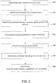
- FIG 2 is a flow chart of an exemplary control method that may be implemented by means of the active voltage limiter unit 15 (shown in Figure 1 ).
- the active voltage limiter unit 15 is configured to implement the control method to control the current regulator system 14 in order to limit the voltage Vdc(t) of the DC-link capacitor 11 during a regeneration mode as well as the minimum voltage during high-torque demands within a predetermined voltage range .
- the control method implemented by the active voltage limiter unit 15 uses a control parameter/signal, indicated hereinafter as estimated “active current ia(t)" (estimated from available and motor phase-currents and commanded duty- cycle signals to the inverter), and the voltage Vdc(t) of the DC-link capacitor 11 to determine the current correction values iqcorr(t) and idcorr(t) to be used to modify the current references iqref and idref that current regulator system 14 uses to control the electric motor 2.
- estimated active current ia(t) estimated from available and motor phase-currents and commanded duty- cycle signals to the inverter
- Vdc(t) of the DC-link capacitor 11 to determine the current correction values iqcorr(t) and idcorr(t) to be used to modify the current references iqref and idref that current regulator system 14 uses to control the electric motor 2.
- Control method performed by the active voltage limiter unit 15 controls the voltage Vdc(t) of the DC-link capacitor 11 in order to "clamp" the voltage Vdc(t) to a constant value in case, for example, the electric motor 2 tends to regenerate back-current ( ip(t) becomes negative) to the DC-link capacitor 10 (i.e. during breaking of the motor).
- the situation of negative DC-link current ip(t) ⁇ 0 can be detected through the computation of the said active current ia(t), that surrogates the unavailable current ip(t). Consequently, the method controls iqrefmod and idrefmod in order to limit the negative active current ia(t) till bringing it to zero if necessary (to completely cancel any back-current to the capacitor).
- the input stage 4 is a passive uncontrolled rectifier
- the current ir(t) > 0 current that flows from the rectifier to the DC-link capacitor
- the current ir(t) is uncontrollable (and fluctuates at twice the mains frequency) and, for the small capacitance of the DC-link capacitor 11, when ir(t) by chance approaches zero, even a small negative ip(t) (regeneration current occurring in braking operation) may cause a large voltage overshoot. This situation may harm the electronic components of the motor controller stage 6, which may fail due to overvoltage.
- the control method uses the active current ia(t), which is obtained by combining the measurements of the phase currents with the duty cycle commands, to detect the regeneration (i.e., the occurrence of back-currents).
- the active current ia(t) can be shown by algebraic formalism to correspond to a scaled version of the current ip(t), that is, the active current ia(t) can be used in place of the current ip(t) to detect regeneration and then to take provisions to limit the capacitor voltage Vdc(t).
- controlling the active current ia(t), in view of Equation (10), is equivalent to controlling ip(t).
- zeroing ia(t) corresponds to nullifying ip(t).
- the signal iaref(t) gives coarse forecast about what will be the active current after the transitory, since the current regulators will drive the currents toward the references.
- Flow chart of Figure 2 contains the operations performed by the active voltage limiter unit 15 to modify the current references of the current regulator system 14 in order to limit the voltage Vdc(t) of the DC-link capacitor 11 during regeneration mode, for example caused by braking or by an external sudden decrease of the load torque.
- control method performs the step of determining the instantaneous active currents ia(t) and iaref(t) based on: the duty cycles Ud(t), Uq(t), the available currents id(t), iq(t) and the current references idref, iqref (block 100) (using the axis d and q of the Clark transformation matrices).
- the active current can be computed alternatively resorting to currents and duty cycles in a reference frame different from the synchronous one, for instance using quantities expressed in the synchronous reference frame ⁇ - ⁇ , when available.
- maximum absolute correction signals idmax(t) and iqmax(t) represent the maximum absolute corrections that yield to a zero the active current iaref(t) when subtracted entirely from the respective currents id and iq.
- nullifying the active current ia(t) corresponds to completely stop any regeneration of current. Applicant has found that to avoid overvoltage, it is not necessary to apply the maximum corrections. Only a fraction of idmax(t) and iqmax(t) may be conveniently applied, depending on a voltage level and on some user-defined tuning parameters. Indeed, depending on the voltage level, the active current ia(t) can take also small negative values (that is, to regenerate) with bottom limit - ialstAbs(t), wherein ialstAbs(t) is an absolute value computed at next step.
- weight coefficient ⁇ v (t) may be 1 if voltage Vdc(t) is below the nominal DC-link voltage Vdcnom
- weight coefficient wV(t) may be 0 if voltage Vdc(t) is above highvoltage limit Vhigh.
- the method may decreases the weight coefficient ⁇ v (t) linearly from 1 to 0 as the DC-link capacitor voltage Vdc(t) changes in a prefixed range comprised between nominal DC-link voltage Vdcnom to high-voltage limit Vhigh.
- w V t sat V high ⁇ V dc t V high ⁇ V dc nom 0 1
- the method may only permit the q-axis correction to negative and vice-versa.
- the method can perform a d-axis correction that is negative and amplified in case the constrained q-axis correction is different from the unconstrained one.
- the active voltage limiter unit has the technical effect of reducing the magnitude of the active current to zero when current starts to became negative, by modifying the current parameters through rotation of the controlled current vector.
- capacitor-less inverter-based apparatus is less expensive and less bulky compared to the known inverter-based apparatus. Indeed inverter-based apparatus limits harmonics without usage of dedicated circuitry (PFC), increasing the lifetime expectation of the inverter thanks to, for example, the usage of a film capacitor instead of an electrolytic type. Moreover, capacitor-less inverter-based apparatus reduces EMC emission due to the limited voltage applied during switching.
- PFC dedicated circuitry
Abstract
Description
- The present invention relates to an inverter based apparatus and control method thereof. More specifically, the present invention relates to an inverter based apparatus configured to operate a motor, in particular a permanent magnet motor or an induction motor or any other similar motor, of an household appliance, such as, for example, a washing machine, a drying machine, a refrigerator and/or dish washer and/or air conditioner. It is understood that according to the present invention, the inverter controlling method and apparatus are designed to control a motor associated to any kind of load of a household appliance, such as, for example, a drum, a compressor, a fan, a pump, etc..
- As is known, nowadays inverters driving motors are widely applied to home appliances. In general, an inverter driving motor comprises an input stage and an inverter bridge, which is provided, in turn, with a plurality of switching units, which are controlled in order to generate and modulate an AC voltage to be fed to motor terminals. The input stage generally comprises a diode bridge having inputs coupled to mains for receiving the AC mains voltage, outputs for providing a DC voltage, and an electrolytic capacitor for removing voltage ripples which appear in rectified voltage.
- Depending on the power size, the inverters for home appliances are usually configured in order to have a high capacitance so as to keep the ripple voltage, and thus a ripple current, within a reasonable level, generally comprised between 10% to 15%. Indeed the electrolytic capacitor worsen the life expectation if the ripple voltage/current increases, and a small ripple voltage is recommended for a seamless drive of the motor. However, if on the one side a flat and stable DC voltage across capacitor, i.e. low ripple voltage, improves the performance of motor driving algorithms, on the other side it affects the mains current by harmonics.
- In order to solve such problem, inverters for home appliances are usually provided with a power factor corrector unit (active or passive) which comprises an inductor having enough inductance to increase the power factor (thus the harmonics) to the desired value. However, factor corrector unit has the disadvantage to be an expensive and bulky component.
- Aim of the present invention is to solve the drawbacks referred above.
- In compliance with the above aims, according to the present invention there is provided an inverter-based apparatus configured to control an electric motor, the inverter-based apparatus comprising: an input stage which is connected to mains lines for receiving AC lines currents and AC mains voltage and configured to convert said AC mains voltage to a rectified DC voltage; an electrolytic-capacitor-less inverter, which is configured to generate output currents to be fed to said electric motor based on duty cycles of switching signals; a DC-link which connects said electrolytic-capacitor-less inverter to the input stage and is crossed by DC-link currents from, or towards, said electrolytic-capacitor-less inverter; a DC-link capacitor connected to said DC-link; a voltage sensor configured to determine the amplitude of said DC-link capacitor voltage; one or more current sensors configured to determine the amplitude of output currents provided to said electric motor by said electrolytic-capacitor-less inverter, and a current regulator system which is configured to control said duty cycles based on determined current references and said output currents, the inverter-based apparatus further comprises an active voltage limiter unit, which is configured to regulate said current references of said current regulator system in order to limit said DC-link capacitor voltage within a predetermined voltage range.
- Preferably, the active voltage limiter unit is further configured to regulate said current references of said current regulator system without using said lines currents and/or DC-link currents and/or the current of the DC capacitor.
- Preferably, said active voltage limiter unit is further configured to clamp said DC-link capacitor voltage to a prefixed value, when said electric motor regenerates back current to said the DC-link capacitor via said electrolytic-capacitor-less inverter.
- Preferably, said active voltage limiter unit is further configured to determine an active current based on said output currents and said duty cycles, and regulate said current references based on said active current and said DC-link capacitor voltage.
- Preferably, said active voltage limiter unit is configured to determine a first active current based on the d-q axis-wise duty cycles indicative of said duty cycles of the switching signals and d-q axis-wise currents indicative of said output currents.
- Preferably, said active voltage limiter unit is configured to determine a second active current based on the d-q axis-wise duty cycles indicative of said duty cycles of the switching signals and said current references.
- Preferably, said active voltage limiter unit is configured to determine said active current, by computing the minimum between said first and second active currents.
- Preferably, said active voltage limiter unit is configured to determine two maximum absolute correction signals on the basis of said second active current and said d-q axis-wise duty cycles.
- Preferably, said active voltage limiter unit is configured to determine an instantaneous maximum allowable regeneration current based on a measured voltage level and a parameter indicative of a maximum absolute active current for regeneration.
- Preferably, the active voltage limiter unit is configured to determine an instantaneous maximum allowable regeneration current ialstAbs(t) based on the following equation

- Preferably, said active voltage limiter unit is configured to determine unconstrained axis-wise corrections to the reference currents as a fraction of the maximum correction by the following equation:


- Preferably, said active voltage limiter unit is configured to determine constrained axis-wise current corrections by applying the following saturation and correction equations


- Preferably, said active voltage limiter unit is configured to modify said current references according to the following equations:

- The present invention further relates to a control method implemented by an inverter-based apparatus configured to control an electric motor, wherein said inverter-based apparatus comprises: an input stage which is connected to mains lines for receiving AC lines currents and AC mains voltage and configured to convert said alternating mains voltage AC to a rectified DC voltage; an electrolytic-capacitor-less inverter, which is configured to generate output currents to be fed to said electric motor based on duty cycles of switching signals; a DC-link which connects said electrolytic-capacitor-less inverter to said input stage and is crossed by DC-link currents from, or towards, said electrolytic-capacitor-less inverter; a DC-link capacitor connected to said DC-link; a voltage sensor configured to determine the amplitude of said DC-link capacitor voltage; one or more current sensors configured to determine the amplitude of output currents provided to said electric motor by said electrolytic-capacitor-less inverter; and a current regulator system which is configured to control said duty cycles based on determined current references and said output currents; said control method being characterized by regulating said current references of said current regulator system in order to limit said DC-link capacitor voltage within a predetermined voltage range.
- So, more generally, the present invention relates also to a method for controlling an electric motor by an apparatus comprising an input stage to convert an AC mains voltage to a rectified DC voltage, an electrolytic capacitor-less inverter connected to the input stage by a DC-link, and a capacitor connected to the DC-link, the method comprising the following steps:
- generating, by the electrolytic capacitor-less inverter, output currents to be fed to the electric motor based on duty cycles of switching signals;
- determining the output currents fed to the electric motor;
- controlling the duty cycles based on current references and the determined output currents;
- determining the voltage across the capacitor; and
- regulating the current references so as to limit the capacitor voltage within a predetermined voltage range.
- Preferably, the control method comprises regulating said current references of said current regulator system without using said lines currents and/or any DC-link currents and/or the current of the DC capacitor.
- Preferably, the control method comprises the step of clamping said DC-link capacitor voltage to a prefixed value, when said electric motor regenerates back current to said the DC-link capacitor via said electrolytic-capacitor-less inverter.
- Preferably, the control method comprises the step of determining an active current based on said output currents and said duty cycles; regulating said current references based on said active current and said DC-link capacitor voltage.
- Preferably, the method comprises the step of determining a first active current based on the d-q axis-wise duty cycles indicative of said duty cycles of the switching signals and d-q axis-wise currents indicative of said output currents.
- Preferably, the method comprises the steps of determining a second active current based on the d-q axis-wise duty cycles indicative of said duty cycles of the switching signals and said current references.
- Preferably, the method comprises the step of determining said active current, by computing the minimum between said first and second active currents.
- Preferably, the method comprises the step of determining two maximum absolute correction signals on the basis of said second active current and said d-q axis-wise duty cycles.
- Preferably, the method comprises determining an instantaneous maximum allowable regeneration current based on a measured voltage level and a parameter indicative of a maximum absolute active current for regeneration.
- Preferably, the method comprises the step of determining an instantaneous maximum allowable regeneration current ialstAbs(t) based on the following equation

- Preferably, said active voltage limiter unit is configured to determine unconstrained axis-wise corrections to the reference currents as a fraction of the maximum correction by the following equation:


- Preferably, the method comprises the step of determining constrained axis-wise current corrections by applying the following saturation and correction equations


- Preferably, the method comprises the step of modifing said current references according to the following equations:


- A non-limiting embodiment of the present invention will now be described, by way of example, with reference to the accompanying drawings, in which:
-
Figure 1 is a block diagram of an inverter-based apparatus provided according to the present invention; and -
Figure 2 is a flow chart of operation implemented by an active voltage limiter unit. - With reference to
Figure 1 ,reference number 1 denotes as a whole an inverter-basedapparatus 1 configured to control anelectric motor 2 according to the control method disclosed hereinafter. Preferably, the electric motor is a three-phase motor 2, but it can be any kind ofmulti-phases motor 2, such as bi-phase or poly-phases motor, or similar motor. Moreover, theelectric motor 2 may be a permanent magnet motor or an induction motor or any other similar motor. - According to a preferred embodiment, the
electric motor 2 may be comprised in a household appliance (not illustrated). The household appliance may be, for example, a washing machine, and/or a drying machine, or a refrigerator, or a dish washer, or an air conditioner, or any similar domestic machine. Preferably, the inverter-basedapparatus 1 is configured to control anelectric motor 2 associated to a component/load of the household appliance such as, for example, a drum, a compressor, a fan, a pump, or any other device/element of the household appliance driven by theelectric motor 2. - With reference to
Figure 1 , the inverter-basedapparatus 1 comprises an input stage 4, aninverter 5 and a motor controller stage 6. - According to an exemplary embodiment illustrated in
Figure 1 , the input stage 4 comprises a rectifier unit configured to convert an alternating voltage AC, received in input from apower supply system 8, to a rectified DC voltage to be provided in input to theinverter 5. The input stage 4 may comprise, for example, a full-bridge diode rectifier having inputs coupled to AC mains lines of thepower supply system 8 for receiving AC mains lines currents and AC mains voltage, and outputs connected to theinverter 5. It is understood that bothpower supply system 8 and input stage 4 depend on the kind of inverter and motor to be controlled. For example,power supply system 8 and input stage 4 may be three-phases, or multi-phases, or similar. - According to an exemplary embodiment illustrated in
Figure 1 , theinverter 5 is configured to convert the DC voltage to AC voltage. Theinverter 5 may be provided with a plurality of switching units (not illustrated), which are controlled by the motor controller stage 6 in order to generate and modulate an AC voltage to be fed to themotor 2. In the exemplary embodiment, theinverter 5 comprises inputs connected to outputs of the input stage 4 to receive the DC voltage and outputs connected to theelectric motor 2. - According to a preferred embodiment, the rectifier unit of the input stage 4 comprises a single-phase rectification circuity, while the
inverter 5 comprises a three-phase inverter having two inputs connected to respective outputs of the rectifier unit and three outputs connected to respective terminals of theelectric motor 2. - With reference to
Figure 1 , the inverter-basedapparatus 1 further comprises a DC-link 10, in turn comprising two DC-link lines, connecting the outputs of the input stage 4 with the inputs of theinverter 5, acapacitor 11, acurrent sensor 12, and avoltage sensor 13. The DC-link capacitor 11 is connected between the two DC-link lines of the DC-link 10, i.e. between the outputs terminals of the input stage 4. Conveniently, the DC-link capacitor 11 may have a capacitance comprised between about 1 µF and about 2 µF. The Applicant has found that using a DC-link capacitor 11 with low-capacitance has the technical effect of increasing the ripple voltage up to 100% so to have a very good harmonic content in the mains current, which allows to eliminate the power factor corrector unit. - In other words, using the DC-
link capacitor 11 with low-capacitance has the advantage of removing any expensive and bulky power factor corrector circuit specifically designed for correction of harmonics (such as an inductor coupled in series between the mains output and the diode bridge input), since, due to the small capacitance of the DC-link capacitor 11, the rectified current still has a substantial harmonic content. Preferably, the DC-link capacitor 11 may comprise a film type capacitor. The film type capacitor is conveniently less expensive and more durable compared to an electrolytic capacitor. Since theinverter 5 does not comprise an electrolytic capacitor, it corresponds to an "electrolytic-capacitor-less inverter". - The
current sensor 12 can be configured to sense the output currents of theinverter 5 applied to theelectric motor 2. With reference to exemplary embodiment illustrated inFigure 1 ,current sensor 12 may comprise one or more sensors configured to sense the currents provided to the three-phase motor 2, i.e. phase currents iu(t), iv(t), iw(t). It is understood that the time-depedence of the currents iu(t), iv(t), iw(t) is not illustrated in Figures the sake of clarity. - The
voltage sensor 13 is preferably configured to sense the voltage Vdc(t) of the DC-link capacitor 10. - With reference to
Figure 1 , the motor controller stage 6 may comprise acurrent regulator system 14 and an activevoltage limiter unit 15. - The
current regulator system 14 is configured to receive information on the sensed currents iu(t) ,iv(t), iw(t) from thecurrent sensor 12, receive information on the sensed voltage Vdc(t) from thevoltage sensor 13, receive information on a motor control parameter i.e. a requested motor speed Spdref provided by an appliance control unit (not illustrated), and to generate three signals Uu(t), Uv(t), Uw(t) to control the switching units of theinverter 5. - The signals Uu(t), Uv(t), Uw(t) may be indicative of duty cycles of the command signals provided to the switching units of the
inverter 5. The signals Uu(t), Uv(t), Uw(t) may be also per-unit signals indicative of the fraction of DC-link voltage to be applied to each phase of the motor. The three signals Uu(t), Uv(t), Uw(t) may be pulse width modulation signals (PWM). - According to an embodiment shown in
Figure 1 , thecurrent regulator system 14 may comprise: ansubtractor stage 20, aspeed control stage 21, aflux weakening stage 22, acurrents regulator stage 23, an inverse-Park transform stage 24, an inverse-Clarke convert stage 25, a direct-Clarke convert stage 26, a direct-Park transform stage 27, and a sensorless speed/fluxposition observer stage 28. - The direct-
Clarke convert stage 26 is configured to convert the three-phase sensed currents iu(t), iv(t), iw(t) into a two-phase α,β Park-coordinate system (stationary reference frame), and provide current values iα(t) and iβ(t) to the direct-Park transform stage 27 and to the sensorless speed/fluxposition observer stage 28. - The sensorless speed/flux
position observer stage 28 is configured to receive the three-phase sensed currents iu(t), iv(t), iw(t) and two signals Uα(t) and Uβ(t). The signals Uα(t) and Uβ(t) are indicative of two duty cycles values in the two-phase α,β Park-coordinate system. The sensorless speed/fluxposition observer stage 28 is further configured to provide a rotor speed signal Spd_feedback relating to the actual speed of the rotor, based on the three-phase sensed currents iu(t), iv(t), iw(t) and the signals Uα(t) and Uβ(t). The sensorless speed/fluxposition observer stage 28 is further configured to provide an angle θestimated indicative of the rotor angle estimated, based on the three-phase sensed currents iu(t), iv(t), iw(t). In an exemplary embodiment, the sensorless speed/fluxposition observer stage 28 may comprise a rotor angular position estimator and rotor angular speed estimator. The rotor angular position estimator may be configured to determine the angular position θestimated of the rotor based on the sensed currents iu(t), iv(t), iw(t) without using a position sensor, whereas the rotor angular speed estimator may be configured to determine the rotor speed Spd_feedback based on the angular position θestimated. - The Park transform
stage 27 is configured to receive the angle θestimated and the measured current values iα and iβ in the two-phase α,β Park-coordinate system (stationary reference frame) and to convert the current values iα(t) and iβ(t) to a two-phase d-q coordinate system (rotating-synchronous reference frame), generating the measured synchronous currents id(t) and iq(t) based on the angle θestimated. - In the exemplary embodiment, the
subtractor stage 20 is configured to receive in input a motor speed signal Spd_ref and the motor speed Spd_feedback. The motor speed signal Speed-ref relates to a reference motor speed associated to a command signal indicating the requested motor speed, whereas the motor speed signal Spd_feedback relates to the determined motor speed provided by the sensorless speed/fluxposition observer stage 28. Thesubtractor stage 20 is configured to determine a speed error based on the difference between input motor speed signals Spd_ref and Spd_feedback. - The
speed control stage 21 is configured to receive the speed error and provide the current iqref. For example, thespeed control stage 21 may comprise a PI controller and is configured to operate in the two-phase d-q coordinate system. The current iqref is indicative of the reference rotor current in the q-axis of the d-q coordinate system. The signals Spd_ref and Spd_feedback, iqref and idref can be, in general, time-varying signals, whose explicit time dependence is not illustrated in the notation to improve clarity of the description. - The
flux weakening stage 22 is configured to operate in the two-phase d-q coordinate system and to generate a reference current idref being indicative of the reference rotor current in the d-axis of the d-q coordinate system. - With regard to the active
voltage limiter unit 15, it is configured to regulate the current references supplied to thecurrent regulator system 23 in order to limit the DC-link capacitor voltage Vdc(t) within a predetermined voltage range. - Preferably, the active
voltage limiter unit 15 is configured to regulate the current references for the Id-Iq current regulators based on the DC-link capacitor voltage Vdc(t) and the measured current values id(t) and iq(t). Conveniently, the activevoltage limiter unit 15 is configured to regulate the current references for the Id-Iq current regulators without using any current measurement in the DC-link. In other words, the inverter-basedapparatus 1 does not comprise any current sensor on the DC-link 10. - Preferably, the active
voltage limiter unit 15 is configured to receive in inputs: the current reference iqref, the current reference idref, the voltage Vdc(t) of the DC-link capacitor 11, two signals Uq(t) and Ud(t) indicative to the duty cycles in a q-d coordinate system (hereinafter disclosed in detail) and the measured current values id(t) and iq(t). The activevoltage limiter unit 15 is further configured to determine two constrained axis-wise current corrections iqcorr(t) and idcorr(t) by implementing the control method hereinafter disclosed in detail. - With reference to
Figure 1 , thecurrent regulator system 14 further comprises anadder unit 30, anadder unit 31, a subtractingunit 32 and a subtractingunit 33. - The
adder unit 30 is configured to receive the current reference iqref and the q-axis-wise current correction iqcorr(t) and to provide in output a modified current reference iqrefmod(t) based on the addition of the current reference iqref and the current correction iqcorr(t). - The
adder unit 31 is configured to receive the current reference idref and the d-axis-wise current correction idcorr(t) and to provide in output a modified current reference idrefmod(t) based on the addition of the current reference idref and the current correction idcorr(t). - The subtracting
unit 32 is configured to receive the modified current reference iqrefmod(t) and the measured current iq(t) and to provide in output the current difference Δiq(t) between the modified current reference iqrefmod(t) and the current iq(t). - The subtracting
unit 33 is configured to receive the modified current reference idrefmod(t) and the measured current id(t) and to provide in output the current difference Δid(t) between the modified reference current idrefmod and the current id. - The
currents regulator stage 23 is configured to receive in input the current difference Δiq(t) and the current difference Δid(t) and to provide in output the signals Uq(t) and Ud(t) respectively based on Δiq(t) and Δid(t). Signals Uq(t) and Ud(t) are indicative of the duty cycles in q-d coordinate system. Signals Uq(t) and Ud(t) may also be indicative of the fraction of maximum voltage to be applied along each axis of the synchronous d-q reference frame. - The inverse-
Park transform stage 24 is configured to receive in input the signals Uq(t) and Ud(t) and to produce the signals Uα(t) and Uβ(t) indicative of the duty cycles values in the two-phase α, β Park-coordinate system. The signals Uα(t) and Uβ(t) may also be indicative of the fraction of maximum voltage to be applied along each axis of the stationary α-β reference frame. - The inverse-
Clarke convert stage 25 is configured to receive in input the signals Uα(t) and Uβ(t) and to provide the switching signals Uu(t), Uv(t), Uw(t) to theinverter unit 5. -
Figure 2 is a flow chart of an exemplary control method that may be implemented by means of the active voltage limiter unit 15 (shown inFigure 1 ). In the exemplary embodiment, the activevoltage limiter unit 15 is configured to implement the control method to control thecurrent regulator system 14 in order to limit the voltage Vdc(t) of the DC-link capacitor 11 during a regeneration mode as well as the minimum voltage during high-torque demands within a predetermined voltage range . - In this respect, the control method implemented by the active
voltage limiter unit 15 uses a control parameter/signal, indicated hereinafter as estimated "active current ia(t)" (estimated from available and motor phase-currents and commanded duty- cycle signals to the inverter), and the voltage Vdc(t) of the DC-link capacitor 11 to determine the current correction values iqcorr(t) and idcorr(t) to be used to modify the current references iqref and idref thatcurrent regulator system 14 uses to control theelectric motor 2. - Control method performed by the active
voltage limiter unit 15 controls the voltage Vdc(t) of the DC-link capacitor 11 in order to "clamp" the voltage Vdc(t) to a constant value in case, for example, theelectric motor 2 tends to regenerate back-current (ip(t) becomes negative) to the DC-link capacitor 10 (i.e. during breaking of the motor). The situation of negative DC-link current ip(t)<0 can be detected through the computation of the said active current ia(t), that surrogates the unavailable current ip(t). Consequently, the method controls iqrefmod and idrefmod in order to limit the negative active current ia(t) till bringing it to zero if necessary (to completely cancel any back-current to the capacitor). - It will be disclosed hereinafter the meaning of the active current ia(t) used by the control method. Tests performed by Applicant proved that the dynamic of the DC-
link capacitor 11 evolves according to the following equation:
- When the input stage 4 is a passive uncontrolled rectifier, then the current ir(t) > 0 (current that flows from the rectifier to the DC-link capacitor) is uncontrollable (and fluctuates at twice the mains frequency) and, for the small capacitance of the DC-
link capacitor 11, when ir(t) by chance approaches zero, even a small negative ip(t) (regeneration current occurring in braking operation) may cause a large voltage overshoot. This situation may harm the electronic components of the motor controller stage 6, which may fail due to overvoltage. - In this respect, the control method uses the active current ia(t), which is obtained by combining the measurements of the phase currents with the duty cycle commands, to detect the regeneration (i.e., the occurrence of back-currents). Indeed the active current ia(t) can be shown by algebraic formalism to correspond to a scaled version of the current ip(t), that is, the active current ia(t) can be used in place of the current ip(t) to detect regeneration and then to take provisions to limit the capacitor voltage Vdc(t).
- More specifically, in order to improve the clarity and facilitate the understanding of the present invention, but without this implying any loss of generality, it will be described hereinafter how the active current ia(t) controlled by the method according to the present invention relates to the current ip(t).
- The instantaneous active power P(t), that is the power absorbed from (if P(t) > 0) or supplied back to (if P(t) < 0) the DC-link, may be expressed in terms of DC-link quantities:

- The instantaneous current ip(t) absorbed from (if ip(t) > 0) or supplied back/regenerated to the DC-link capacitor 11 (if ip(t) < 0), can be computed by inverting equation (1) :

- The active power P(t) can also be expressed in terms of the phase currents and voltages of the motor 2 (referred to the motor's neutral point) by the scalar product:


- Neglecting the zero-sequence current and voltage (V0,i0), the following simplified form for the active power is considered:

- Considering that voltages Vd(t) and Vq(t) are applied through a standard Space Vector Modulation switching strategy, they relate to the duty cycles Ud(t) and Uq(t) [PU] by


- By defining the active current ia(t):


- Therefore, Applicant has found that controlling the active current ia(t), in view of Equation (10), is equivalent to controlling ip(t). In particular, zeroing ia(t) corresponds to nullifying ip(t).
- In case harmful regeneration is detected (negative ia(t) or increasing capacitor voltage Vdc(t)) then, as a first provision, it is possible to stop the regeneration current by nullifying ia(t).
- Besides ia(t), it is possible to use another synthetic signal, named iaref(t), that gives an anticipation (forecast) on what will be the value of the active current ia(t) after the current regulators have settled. Indeed, in a motor drive with current-regulators (for id(t) and iq(t)), the currents are commanded to prescribed values idref and iqref, and the regulators are in charge of obtaining the required currents by computing suitable duty cycles, to be actuated by the inverter unit.
- For a prescribed pair of reference currents, it is defined the-reference-active current-at-time-t, the signal computed with the reference currents and the duty cycles at time t:

- For a change in the reference currents (commanded in turn by a speed/torque controller or by a flux/weakening or magnetization block), the signal iaref(t) gives coarse forecast about what will be the active current after the transitory, since the current regulators will drive the currents toward the references.
- Flow chart of
Figure 2 contains the operations performed by the activevoltage limiter unit 15 to modify the current references of thecurrent regulator system 14 in order to limit the voltage Vdc(t) of the DC-link capacitor 11 during regeneration mode, for example caused by braking or by an external sudden decrease of the load torque. - Firstly, the control method performs the step of determining the instantaneous active currents ia(t) and iaref(t) based on: the duty cycles Ud(t), Uq(t), the available currents id(t), iq(t) and the current references idref, iqref (block 100) (using the axis d and q of the Clark transformation matrices).
- Preferably, the control method determines the instantaneous active currents ia(t) and iaref(t) by the formulas:

- It is understood that the active current can be computed alternatively resorting to currents and duty cycles in a reference frame different from the synchronous one, for instance using quantities expressed in the synchronous reference frame α- β , when available.

- Moreover, the control method performs the step of determining a worst-case active current iaws(t) (block 110), by computing the minimum between the active currents ia(t) and iaref(t) determined by Equation (12):

- The method further performs the step of determining two maximum absolute correction signals idmax(t) and iqmax(t) (block 120), using the value iaref(t) computed by Equation (12a) :

- Applicant has found that maximum absolute correction signals idmax(t) and iqmax(t) represent the maximum absolute corrections that yield to a zero the active current iaref(t) when subtracted entirely from the respective currents id and iq. In this respect, the modified active current computed with the modifications yields:

- Applicant has found that that nullifying the active current ia(t) corresponds to completely stop any regeneration of current. Applicant has found that to avoid overvoltage, it is not necessary to apply the maximum corrections. Only a fraction of idmax(t) and iqmax(t) may be conveniently applied, depending on a voltage level and on some user-defined tuning parameters. Indeed, depending on the voltage level, the active current ia(t) can take also small negative values (that is, to regenerate) with bottom limit - ialstAbs(t), wherein ialstAbs(t) is an absolute value computed at next step.
- Furthermore, the method performs the step of determining the instantaneous maximum allowable regeneration current ialstAbs(t) (block 130) based on the measured voltage level and a prefixed parameter iaMaxAbs corresponding to a maximum absolute active current for regeneration, for example defined by the user:


- Furthermore, the method determines the negative fraction of correction to be applied according, for example, to the empirical saturated-cubic Equation (block 140):

- It is understood that when there is regeneration, the current iaws(t) is negative. Therefore only for active currents ia(t) below the instantaneous limit - ialstAbs(t), the fraction p(t) counts negative and different from zero.
- Furthermore, the method determines the unconstrained d-q axis-wise corrections as a fraction of the maximum correction by the following Equation (block 150):

- Furthermore, the method determines the constrained d-q axis-wise current corrections by applying the following saturation and correction Equations (block 160):


- For example, when the motor speed is positive, the method may only permit the q-axis correction to negative and vice-versa.
- The method can perform a d-axis correction that is negative and amplified in case the constrained q-axis correction is different from the unconstrained one.
- Furthermore, the method may determine the modified current references for the current regulators (block 160) by the
adders 30, 31:
- The advantages resulting from the use of the active
voltage limiter unit 15 in the inverter-basedapparatus 1 are remarkable. - The active voltage limiter unit has the technical effect of reducing the magnitude of the active current to zero when current starts to became negative, by modifying the current parameters through rotation of the controlled current vector.
- Moreover, the capacitor-less inverter-based apparatus is less expensive and less bulky compared to the known inverter-based apparatus. Indeed inverter-based apparatus limits harmonics without usage of dedicated circuitry (PFC), increasing the lifetime expectation of the inverter thanks to, for example, the usage of a film capacitor instead of an electrolytic type. Moreover, capacitor-less inverter-based apparatus reduces EMC emission due to the limited voltage applied during switching.
Claims (15)
- Inverter-based apparatus (1) configured to control an electric motor (2), the inverter-based apparatus comprising:an input stage (4), which is connected to mains lines (8) for receiving AC lines currents and AC mains voltage and configured to convert said alternating mains voltage AC to a rectified DC voltage;an electrolytic-capacitor-less inverter (5), which is configured to generate output currents to be fed to said electric motor (2) based on duty cycles of switching signals;a DC-link (10), which connects said electrolytic-capacitor-less inverter (5) to said input stage (4) and is crossed by DC-link currents from, or towards, said electrolytic-capacitor-less inverter (5);a DC-link capacitor (11) connected to said DC-link (10);a voltage sensor (13) configured to determine the amplitude of said DC-link capacitor voltage (Vdc(t));one or more current sensors (12) configured to determine the amplitude of output currents provided to said electric motor (2) by said electrolytic-capacitor-less inverter (5); anda current regulator system (14), which is configured to control said duty cycles based on determined current references (idref, iqref) and said output currents,said inverter-based apparatus (1) being characterized by comprising an active voltage limiter unit (15), which is configured to regulate said current references (idref, iqref) of said current regulator system (14) in order to limit said DC-link capacitor voltage (Vdc(t)) within a predetermined voltage range.
- Inverter-based apparatus according to claim 1, wherein said active voltage limiter unit (15) is further configured to regulate said current references (idref, iqref) of said current regulator system (14) without using said lines currents and/or DC-link currents.
- Inverter-based apparatus according to claims 1 or 2, wherein said active voltage limiter unit (15) is further configured to clamp said DC-link capacitor voltage (Vdc(t)) to a prefixed value, when said electric motor (2) regenerates back current to said the DC-link capacitor (11) via said electrolytic-capacitor-less inverter (5).
- Inverter-based apparatus according to any of the previous claims, wherein said active voltage limiter unit (15) is further configured to:determine an active current (ia)(iaref) based on said output currents (iu, iv, iw) and said duty cycles; andregulate said current references (idref, iqref) based on said active current (ia)(iaref) and said DC-link capacitor voltage (Vdc(t)) .
- Inverter-based apparatus according to claim 4, wherein said active voltage limiter unit (15) is further configured to determine a first active current (ia) based on d-q axis-wise duty cycles (Ud, Uq) which are indicative of said duty cycles of the switching signals and d-q axis-wise currents (id, iq) indicative of said output currents (iu, iv, iw).
- Inverter-based apparatus according to claims 4 or 5, wherein said active voltage limiter unit (15) is configured to determine a second active current (iaref) based on the d-q axis-wise duty cycles (Ud, Uq) indicative of said duty cycles of the switching signals and said determined current references (idref, iqref).
- Inverter-based apparatus according to claims 6 when depending on claim 5, wherein said active voltage limiter unit (15) is further configured to determine said active current (iaws) by computing a minimum current between said first (ia(t)) and second active currents (iaref(t)).
- Inverter-based apparatus according to claim 7, wherein said active voltage limiter unit (15) is further configured to determine two maximum absolute correction signals (idmax(t), iqmax(t)) on the basis of said second active current (iaref) and said d-q axis-wise duty cycles (Ud, Uq).
- Inverter-based apparatus according to claim 8, wherein said active voltage limiter unit (15) is further configured to determine an instantaneous maximum allowable regeneration current (ialstAbs(t)) based on a measured voltage level and a parameter (iaMaxAbs) indicative of a maximum absolute active current for regeneration.
- Inverter-based apparatus according to claim 9, wherein said active voltage limiter unit (15) is further configured to determine an instantaneous maximum allowable regeneration current (ialstAbs(t)) based on the following equation

- Inverter-based apparatus according to claim 10, wherein said active voltage limiter unit (15) is further configured to determine a negative fraction of correction to be applied according to an empirical saturated-cubic equation:

- Inverter-based apparatus according to claim 11, wherein said active voltage limiter unit (15) is further configured to determine unconstrained axis-wise corrections as a fraction of the maximum correction by the following equation:


- Inverter-based apparatus according to claim 12, wherein said active voltage limiter unit (15) is further configured to determines constrained axis-wise current corrections by applying the following saturation and correction equations

 Kqd is a positive tuning gain that may be used to transfer to the d-axis part of the correction originally computed for the q-axis, when saturation occurs,idunc and iqunc are said axis-wise current corrections .
 - An electric appliance, comprising an electric motor (2) and an inverter-based apparatus (1) according to anyone of claims 1 to 13 to control the electric motor (2).
- Method to control an electric motor by an apparatus comprising an input stage to convert an AC mains voltage to a rectified DC voltage, an electrolytic capacitor-less inverter connected to the input stage by a DC-link, and a capacitor connected to the DC-link, the method comprising the steps of:• generating, by the electrolytic capacitor-less inverter, output currents to be fed to the electric motor based on duty cycles of switching signals;• determining the output currents fed to the electric motor;• controlling the duty cycles based on current references and the determined output currents;• determining the voltage across the capacitor; and• regulating the current references so as to limit the capacitor voltage within a predetermined voltage range.
Priority Applications (11)
| Application Number | Priority Date | Filing Date | Title |
|---|---|---|---|
| EP18185870.5A EP3599708A1 (en) | 2018-07-26 | 2018-07-26 | Inverter based apparatus and control method thereof |
| EP19737798.9A EP3827508A1 (en) | 2018-07-26 | 2019-07-17 | Inverter based apparatus and control method thereof |
| AU2019309255A AU2019309255A1 (en) | 2018-07-26 | 2019-07-17 | Inverter based apparatus and control method thereof |
| BR112021001256-7A BR112021001256A2 (en) | 2018-07-26 | 2019-07-17 | inverter-based apparatus, electrical equipment and method for controlling an electric motor |
| PCT/EP2019/069227 WO2020020719A1 (en) | 2018-07-26 | 2019-07-17 | Inverter based apparatus and control method thereof |
| CN201980047658.9A CN112425054B (en) | 2018-07-26 | 2019-07-17 | Inverter-based device and control method thereof |
| CN201980049163.XA CN112470382A (en) | 2018-07-26 | 2019-07-25 | Laundry treatment machine and method for operating a laundry treatment machine |
| US17/262,027 US11750137B2 (en) | 2018-07-26 | 2019-07-25 | Laundry treating machine and method for operating a laundry treating machine |
| EP19742610.9A EP3827509A1 (en) | 2018-07-26 | 2019-07-25 | Laundry treating machine and method for operating a laundry treating machine |
| PCT/EP2019/070031 WO2020021005A1 (en) | 2018-07-26 | 2019-07-25 | Laundry treating machine and method for operating a laundry treating machine |
| US18/201,458 US20230318508A1 (en) | 2018-07-26 | 2023-05-24 | Laundry treating machine and method for operating a laundry treating machine |
Applications Claiming Priority (1)
| Application Number | Priority Date | Filing Date | Title |
|---|---|---|---|
| EP18185870.5A EP3599708A1 (en) | 2018-07-26 | 2018-07-26 | Inverter based apparatus and control method thereof |
Publications (1)
| Publication Number | Publication Date |
|---|---|
| EP3599708A1 true EP3599708A1 (en) | 2020-01-29 |
Family
ID=63077812
Family Applications (3)
| Application Number | Title | Priority Date | Filing Date |
|---|---|---|---|
| EP18185870.5A Withdrawn EP3599708A1 (en) | 2018-07-26 | 2018-07-26 | Inverter based apparatus and control method thereof |
| EP19737798.9A Pending EP3827508A1 (en) | 2018-07-26 | 2019-07-17 | Inverter based apparatus and control method thereof |
| EP19742610.9A Ceased EP3827509A1 (en) | 2018-07-26 | 2019-07-25 | Laundry treating machine and method for operating a laundry treating machine |
Family Applications After (2)
| Application Number | Title | Priority Date | Filing Date |
|---|---|---|---|
| EP19737798.9A Pending EP3827508A1 (en) | 2018-07-26 | 2019-07-17 | Inverter based apparatus and control method thereof |
| EP19742610.9A Ceased EP3827509A1 (en) | 2018-07-26 | 2019-07-25 | Laundry treating machine and method for operating a laundry treating machine |
Country Status (6)
| Country | Link |
|---|---|
| US (2) | US11750137B2 (en) |
| EP (3) | EP3599708A1 (en) |
| CN (2) | CN112425054B (en) |
| AU (1) | AU2019309255A1 (en) |
| BR (1) | BR112021001256A2 (en) |
| WO (2) | WO2020020719A1 (en) |
Cited By (1)
| Publication number | Priority date | Publication date | Assignee | Title |
|---|---|---|---|---|
| CN113098365A (en) * | 2021-03-25 | 2021-07-09 | 西安交通大学 | Method and system for suppressing network side current harmonic of motor driving system without electrolytic capacitor |
Citations (2)
| Publication number | Priority date | Publication date | Assignee | Title |
|---|---|---|---|---|
| WO2014130201A1 (en) * | 2013-01-24 | 2014-08-28 | Regal Beloit America, Inc. | Methods and systems controlling an electric motor |
| US20140265987A1 (en) * | 2013-03-15 | 2014-09-18 | Regal Beloit America, Inc. | Methods and systems for inductive energy management |
Family Cites Families (17)
| Publication number | Priority date | Publication date | Assignee | Title |
|---|---|---|---|---|
| JP3891080B2 (en) | 2002-09-12 | 2007-03-07 | 富士電機システムズ株式会社 | Regenerative control method for motor-driven power converter |
| US8866453B2 (en) * | 2008-08-28 | 2014-10-21 | Intersil Americas LLC | Switching regulator input current sensing circuit, system, and method |
| JP5292363B2 (en) | 2010-06-30 | 2013-09-18 | 株式会社日立製作所 | AC motor control device and control method |
| EP2586898B1 (en) * | 2011-10-25 | 2014-06-04 | Electrolux Home Products Corporation N.V. | Inrush current control system |
| US9331614B2 (en) * | 2013-02-08 | 2016-05-03 | Regal Beloit America, Inc. | Systems and methods for controlling electric machines |
| US9270223B2 (en) * | 2013-04-12 | 2016-02-23 | Deere & Company | Methods of determining machine terminal voltage and systems thereof |
| CN103795081B (en) | 2014-01-27 | 2016-06-01 | 太原科技大学 | The control method of direct-driving type wind power system low voltage crossing |
| KR101663522B1 (en) * | 2015-02-10 | 2016-10-07 | 엘지전자 주식회사 | Motor driving apparatus and laundry treatment machine including the same |
| KR102431991B1 (en) * | 2015-03-13 | 2022-08-16 | 삼성전자주식회사 | Motor driving apparatus |
| KR101979859B1 (en) | 2015-05-08 | 2019-05-17 | 존슨 컨트롤스 테크놀러지 컴퍼니 | Variable speed drive with active converter |
| GB2538493B (en) | 2015-05-12 | 2017-05-10 | Invertek Drives Ltd | A control method and system |
| FR3038796B1 (en) | 2015-07-09 | 2017-08-11 | Moteurs Leroy-Somer | ENERGY GENERATING SYSTEM WITH IMPROVED TREATMENT OF LOAD IMPACTS, DELAYS AND HARMONICS |
| CN205490281U (en) * | 2016-04-11 | 2016-08-17 | 中国矿业大学 | No electrolytic capacitor dc -to -ac converter PMSM controlling means based on repeated control |
| CN106026072B (en) * | 2016-05-18 | 2018-09-11 | 珠海格力电器股份有限公司 | Double PWM converter DC bus-bar voltage fluctuation suppressing methods and control method |
| CN107070286B (en) | 2017-03-09 | 2019-09-20 | 国家电网公司 | Control method for super capacitor energy storage system current transformer |
| CN107359843B (en) * | 2017-07-20 | 2018-07-31 | 奥克斯空调股份有限公司 | Power conversion control system |
| CN107834924B (en) * | 2017-11-27 | 2019-08-27 | 奥克斯空调股份有限公司 | A kind of field weakening control method and device |
-
2018
- 2018-07-26 EP EP18185870.5A patent/EP3599708A1/en not_active Withdrawn
-
2019
- 2019-07-17 EP EP19737798.9A patent/EP3827508A1/en active Pending
- 2019-07-17 WO PCT/EP2019/069227 patent/WO2020020719A1/en active Application Filing
- 2019-07-17 AU AU2019309255A patent/AU2019309255A1/en active Pending
- 2019-07-17 CN CN201980047658.9A patent/CN112425054B/en active Active
- 2019-07-17 BR BR112021001256-7A patent/BR112021001256A2/en unknown
- 2019-07-25 US US17/262,027 patent/US11750137B2/en active Active
- 2019-07-25 WO PCT/EP2019/070031 patent/WO2020021005A1/en active Application Filing
- 2019-07-25 EP EP19742610.9A patent/EP3827509A1/en not_active Ceased
- 2019-07-25 CN CN201980049163.XA patent/CN112470382A/en active Pending
-
2023
- 2023-05-24 US US18/201,458 patent/US20230318508A1/en active Pending
Patent Citations (2)
| Publication number | Priority date | Publication date | Assignee | Title |
|---|---|---|---|---|
| WO2014130201A1 (en) * | 2013-01-24 | 2014-08-28 | Regal Beloit America, Inc. | Methods and systems controlling an electric motor |
| US20140265987A1 (en) * | 2013-03-15 | 2014-09-18 | Regal Beloit America, Inc. | Methods and systems for inductive energy management |
Non-Patent Citations (1)
| Title |
|---|
| DE OLIVEIRA FILHO M E ET AL: "A control method for voltage source inverter without dc link capacitor", POWER ELECTRONICS SPECIALISTS CONFERENCE, 2008. PESC 2008. IEEE, IEEE, PISCATAWAY, NJ, USA, 15 June 2008 (2008-06-15), pages 4432 - 4437, XP031300651, ISBN: 978-1-4244-1667-7 * |
Cited By (1)
| Publication number | Priority date | Publication date | Assignee | Title |
|---|---|---|---|---|
| CN113098365A (en) * | 2021-03-25 | 2021-07-09 | 西安交通大学 | Method and system for suppressing network side current harmonic of motor driving system without electrolytic capacitor |
Also Published As
| Publication number | Publication date |
|---|---|
| CN112470382A (en) | 2021-03-09 |
| WO2020021005A1 (en) | 2020-01-30 |
| CN112425054B (en) | 2023-11-21 |
| AU2019309255A1 (en) | 2021-01-07 |
| US20210297030A1 (en) | 2021-09-23 |
| CN112425054A (en) | 2021-02-26 |
| WO2020020719A1 (en) | 2020-01-30 |
| EP3827508A1 (en) | 2021-06-02 |
| BR112021001256A2 (en) | 2021-04-20 |
| US20230318508A1 (en) | 2023-10-05 |
| US11750137B2 (en) | 2023-09-05 |
| EP3827509A1 (en) | 2021-06-02 |
Similar Documents
| Publication | Publication Date | Title |
|---|---|---|
| US8542502B2 (en) | Electrical power conversion apparatus | |
| US9954475B2 (en) | Motor driving apparatus | |
| EP2034605B1 (en) | Electric motor driving device, and compressor driving device | |
| US9331614B2 (en) | Systems and methods for controlling electric machines | |
| US10778130B2 (en) | Control apparatus for alternating-current rotary electric machine | |
| WO2013105187A1 (en) | Inverter control device | |
| US20190097559A1 (en) | Power conversion device, motor drive device, and refrigerator using same | |
| US20230318508A1 (en) | Laundry treating machine and method for operating a laundry treating machine | |
| EP3021479B1 (en) | Apparatus for controlling inverter | |
| JP3773794B2 (en) | Power converter | |
| US11601080B2 (en) | Motor control device | |
| EP4050788A1 (en) | Power conversion device | |
| JP2013172550A (en) | Motor controller and three-phase voltage command generating method of motor | |
| JP2015029396A (en) | Power conversion device and control method | |
| JP6132934B2 (en) | Power converter | |
| US20240097595A1 (en) | Power conversion device and power conversion method | |
| KR101924400B1 (en) | Apparatus and method for controlling inverter |
Legal Events
| Date | Code | Title | Description |
|---|---|---|---|
| PUAI | Public reference made under article 153(3) epc to a published international application that has entered the european phase |
Free format text: ORIGINAL CODE: 0009012 |
|
| STAA | Information on the status of an ep patent application or granted ep patent |
Free format text: STATUS: THE APPLICATION HAS BEEN PUBLISHED |
|
| AK | Designated contracting states |
Kind code of ref document: A1 Designated state(s): AL AT BE BG CH CY CZ DE DK EE ES FI FR GB GR HR HU IE IS IT LI LT LU LV MC MK MT NL NO PL PT RO RS SE SI SK SM TR |
|
| AX | Request for extension of the european patent |
Extension state: BA ME |
|
| STAA | Information on the status of an ep patent application or granted ep patent |
Free format text: STATUS: REQUEST FOR EXAMINATION WAS MADE |
|
| 17P | Request for examination filed |
Effective date: 20200729 |
|
| RBV | Designated contracting states (corrected) |
Designated state(s): AL AT BE BG CH CY CZ DE DK EE ES FI FR GB GR HR HU IE IS IT LI LT LU LV MC MK MT NL NO PL PT RO RS SE SI SK SM TR |
|
| STAA | Information on the status of an ep patent application or granted ep patent |
Free format text: STATUS: EXAMINATION IS IN PROGRESS |
|
| STAA | Information on the status of an ep patent application or granted ep patent |
Free format text: STATUS: EXAMINATION IS IN PROGRESS |
|
| 17Q | First examination report despatched |
Effective date: 20200904 |
|
| STAA | Information on the status of an ep patent application or granted ep patent |
Free format text: STATUS: THE APPLICATION IS DEEMED TO BE WITHDRAWN |
|
| 18D | Application deemed to be withdrawn |
Effective date: 20210115 |