EP3599525A1 - Verfahren zur sicheren datenkommunikation an einer numerisch gesteuerten werkzeugmaschine - Google Patents
Verfahren zur sicheren datenkommunikation an einer numerisch gesteuerten werkzeugmaschine Download PDFInfo
- Publication number
- EP3599525A1 EP3599525A1 EP19182462.2A EP19182462A EP3599525A1 EP 3599525 A1 EP3599525 A1 EP 3599525A1 EP 19182462 A EP19182462 A EP 19182462A EP 3599525 A1 EP3599525 A1 EP 3599525A1
- Authority
- EP
- European Patent Office
- Prior art keywords
- identification number
- data
- peripheral device
- data telegram
- numerical control
- Prior art date
- Legal status (The legal status is an assumption and is not a legal conclusion. Google has not performed a legal analysis and makes no representation as to the accuracy of the status listed.)
- Granted
Links
Images

Classifications
-
- G—PHYSICS
- G05—CONTROLLING; REGULATING
- G05B—CONTROL OR REGULATING SYSTEMS IN GENERAL; FUNCTIONAL ELEMENTS OF SUCH SYSTEMS; MONITORING OR TESTING ARRANGEMENTS FOR SUCH SYSTEMS OR ELEMENTS
- G05B19/00—Program-control systems
- G05B19/02—Program-control systems electric
- G05B19/418—Total factory control, i.e. centrally controlling a plurality of machines, e.g. direct or distributed numerical control [DNC], flexible manufacturing systems [FMS], integrated manufacturing systems [IMS] or computer integrated manufacturing [CIM]
- G05B19/4185—Total factory control, i.e. centrally controlling a plurality of machines, e.g. direct or distributed numerical control [DNC], flexible manufacturing systems [FMS], integrated manufacturing systems [IMS] or computer integrated manufacturing [CIM] characterised by the network communication
-
- G—PHYSICS
- G05—CONTROLLING; REGULATING
- G05B—CONTROL OR REGULATING SYSTEMS IN GENERAL; FUNCTIONAL ELEMENTS OF SUCH SYSTEMS; MONITORING OR TESTING ARRANGEMENTS FOR SUCH SYSTEMS OR ELEMENTS
- G05B2219/00—Program-control systems
- G05B2219/30—Nc systems
- G05B2219/31—From computer integrated manufacturing till monitoring
- G05B2219/31175—Message comprises identification of sender, receiver, command and parameter
-
- Y—GENERAL TAGGING OF NEW TECHNOLOGICAL DEVELOPMENTS; GENERAL TAGGING OF CROSS-SECTIONAL TECHNOLOGIES SPANNING OVER SEVERAL SECTIONS OF THE IPC; TECHNICAL SUBJECTS COVERED BY FORMER USPC CROSS-REFERENCE ART COLLECTIONS [XRACs] AND DIGESTS
- Y02—TECHNOLOGIES OR APPLICATIONS FOR MITIGATION OR ADAPTATION AGAINST CLIMATE CHANGE
- Y02P—CLIMATE CHANGE MITIGATION TECHNOLOGIES IN THE PRODUCTION OR PROCESSING OF GOODS
- Y02P90/00—Enabling technologies with a potential contribution to greenhouse gas [GHG] emissions mitigation
- Y02P90/02—Total factory control, e.g. smart factories, flexible manufacturing systems [FMS] or integrated manufacturing systems [IMS]
Definitions
- the present invention relates to a method for secure data communication on a numerically controlled machine tool.
- the aim of the method is to ensure that a data telegram that is exchanged between a numerical control and the peripheral devices of the machine tool reliably achieves the intended goal.
- a method for secure data communication on a numerically controlled machine tool is disclosed, with a numerical control acting as a transmitter, which is used to exchange data via a digital network
- Data telegrams is connected to a plurality of peripheral devices acting as receivers, each of which is assigned a unique identification number. This identification number is recalculated both by the controller and by the peripheral device for each transmission of such a data telegram and is part of the data telegram.
- expectations are set up at the receiver that can be used to check whether the data telegram has also reached the correct recipient.
- the method also includes that the identification number includes routing information about the path of the data telegram from the controller to the peripheral device and also a hash value about local data that characterize the peripheral device.
- the Figure 1 shows a numerical control NC, which is connected via a network N to a plurality of peripheral devices U1, U2, U3, U4, U5, U6, U7, U8, U9 of a machine tool WZM.
- peripheral devices U1, U2, U3, U4, U5, U6, U7, U8, U9 are, for example, the converters of the various movable axes of the machine tool WZM controlled by means of the numerical control NC.
- each of these converters U1, U2, U3, U4, U5, U6, U7, U8, U9 can control one or two drives which drive the movable axes of the machine tool WZM.
- a converter is used to convert the alternating current of fixed frequency from a supply network into alternating current of variable frequency, with which, for example, a synchronous motor can move an axis of the machine tool WZM under position control.
- the peripheral devices U1, U2, U3, U4, U5, U6, U7, U8, U9 for example, transmit parameter sets from the numerical control NC with which the respective peripheral devices U1, U2, U3, U4, U5, U6, U7, U8, U9 should be parameterized.
- Such parameters can be, for example, a maximum switch-off time, whether a drive belongs to an axis group or the participation of a drive in a brake line test.
- the transmission or request of specific information between the numerical control NC and the peripheral devices U1, U2, U3, U4, U5, U6, U7, U8, U9 is also handled via the network N.
- the network N is in the Figure 1 shown highly schematically. It comprises several interconnected devices CC1, CC2, CC3, CC4, which in turn contain several computing units c1, c2, c3, c4, which also function as Data flow control units can be characterized. These data flow control units c1, c2, c3, c4 are linked to one another in different ways within the devices CC1, CC2, CC3, CC4, and also between the devices CC1, CC2, CC3, CC4 and to the peripheral devices U1, U2, U3, U4, Various data paths are possible for U5, U6, U7, U8, U9. Different bus systems and network technologies such as Ethernet or SPI can also be used mixed.
- the Figure 2 shows the structure of a data telegram T, which is to be sent from the numerical control NC to the peripheral devices U1, U2, U3, U4, U5, U6, U7, U8, U9 of the machine tool WZM.
- This data telegram T contains a unique identification number ID, which identifies the recipient, and the actual user data P, which are to be transmitted.
- the unique identification number ID comprises routing information R, which prescribe the path of the data telegram T.
- This routing information R takes into account the topology of the network N, which must be known to the sender and the receiver of the data telegram T.
- the routing information R can be inserted in plain text and as a string "CC1_c1_c2_CC3_c3_c4_U7" in the data telegram.
- the routing information is "CC2_c1_c2_c3_U2". Further examples are based on the Figure 1 easy to understand.
- the basic idea of the invention is that the recipient of the data telegram T compares the identification number ID with his expected value for this identification number ID.
- the receiver checks whether the path contained in the data telegram T actually describes the path from the transmitter to the receiver (that is, to it itself), that is to say whether the actual receiver describes the intended recipient equivalent. If this is not the case, either the transmitter and / or the receiver have incorrect information about the topology of the network N. This can be the case if, for example, a network cable was incorrectly inserted during a repair.
- a corresponding error reaction can be triggered. This can be the request for a renewed transmission of the data telegram T or the stopping of the machine tool.
- a hash value H is used as a further component of the identification number ID in addition to the routing information R in the sense of a second, improved exemplary embodiment.
- This hash value H is formed over certain environmental conditions of the receiver. These quantities, which are referred to very abstractly as environmental conditions, can be, for example, type designations, software versions or performance specifications of hardware components. Serial numbers of such hardware components that are only assigned once are less suitable, since they would change when a component was replaced and would then have to be made known to all participants. An exchange for a spare part of the same type would not change the hash value H.
- Certain, particularly worthy of protection parameters can also be included in the hash value H, with which a peripheral device U1, U2, U3, U4, U5, U6, U7, U8, U9 is parameterized. If such a parameter is changed unintentionally (e.g. due to a memory error caused by cosmic radiation), this is noticeable the next time a telegram T is transmitted.
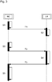
- the Figure 3 shows a flowchart for communication between the numerical control NC and (selected here only as an example for a peripheral device) the peripheral device U4.
- a set of parameters is compiled in the numerical control NC with which the peripheral device U4 is to be parameterized. These parameters are transmitted to the peripheral device U4 in a first data telegram T1.
- the peripheral devices U1, U2, U3, U4, U5, U6, U7, U8, U9 are usually parameterized by entering a set of parameters on the numerical control NC and sending them to the peripheral devices U1, U2, U3, U4, U5, U6, U7, U8, U9 transmits.
- the control NC already knows the routing information R when it transmits these parameters for the first time and can also include one, several or all of the parameters to be transmitted in the hash value H.
- the receiving peripheral unit U4 can check both the routing information R and the hash value H on the basis of the received data message T1, since the parameters required for calculating the hash value H are transmitted as payload P with this message T1.
- a second step S2 the parameters transmitted with the first data telegram T1 are stored in the peripheral device U4. From now on, both the numerical control NC and the peripheral device U4 know this parameter set and can therefore also calculate the hash value H as a component of the identification number ID independently of one another.
- the numerical control NC calculates both the routing information R and the hash value H via the parameters and other environmental conditions in the peripheral device U4 and thus forms the identification number ID for a second data telegram T2, with which a request for transmitting information to the peripheral device U4 is sent.
- the peripheral device U4 receives this second data message T2. It also calculates the identification number ID as an expected value based on the locally available parameters and Ambient conditions and compares this expected value with the identification number ID transmitted in the second data telegram T2. If these two identification numbers differ, an error is recognized and, for example, the machine tool WZM is switched off. However, if both identification numbers ID match, it is ensured that both the correct peripheral device U4 has been addressed and that the parameterization of the peripheral device U4 matches the parameterization specified or accepted by the numerical control NC. If type designations of hardware components of the peripheral device U4 are processed in hash value H, this also ensures that the expected hardware is available and that incorrect components were not installed during maintenance.
- a third data telegram T3 is also created with the response to the request for information in the second data telegram T2.
- the third data telegram T3 thus contains at least this requested information, and possibly also additional information, which are transmitted together as user data P to the numerical control NC.
- the identification number ID of this third data telegram T3 is formed by the peripheral unit U4 according to the same rule as that in the second data telegram T2.
- the identification number ID is therefore information about the sender of the third data telegram T3.
- the numerical control NC can in turn check this identification number ID on the basis of the knowledge available there about the routing information R from the sender and its environmental conditions. The numerical control NC can thus ensure that the third data telegram actually comes from the assumed sender, the peripheral device U4.
- the hash value H is calculated using customary cryptographic methods and is thus also secured against manipulation attempts in the network N.
- suitable cryptographic methods are the methods known under the names MD5, CRC or SHA-1.
Landscapes
- Engineering & Computer Science (AREA)
- General Engineering & Computer Science (AREA)
- Manufacturing & Machinery (AREA)
- Quality & Reliability (AREA)
- Physics & Mathematics (AREA)
- General Physics & Mathematics (AREA)
- Automation & Control Theory (AREA)
- Numerical Control (AREA)
Abstract
Description
- Die vorliegende Erfindung betrifft ein Verfahren zur sicheren Datenkommunikation an einer numerisch gesteuerten Werkzeugmaschine. Mit dem Verfahren soll bewirkt werden, dass ein Datentelegramm, das zwischen einer Numerischen Steuerung und den Peripheriegeräten der Werkzeugmaschine ausgetauscht wird, sicher das vorgesehene Ziel erreicht.
- Im Bereich der numerisch gesteuerten Werkzeugmaschinen wird die Kommunikation zwischen der Numerischen Steuerung und den Peripheriegeräten wie Umrichter, Antriebe, Messgeräte, Bremsen, Notaustaster etc. immer mehr über digitale Schnittstellen abgewickelt. Dabei kommen verschiedenste Bussysteme und Übertragungswege zum Einsatz. Im Vergleich zu direkt angeschlossenen Peripheriegeräten, die beispielsweise analoge Messsignale über ein Kabel an die Steuerung abgeben, muss bei einer Kommunikation über ein Datennetzwerk sichergestellt werden, dass ein Datentelegramm immer den jeweils gewünschten Empfänger erreicht.
- Aus der
EP 1422629 B1 ist es bekannt, an die verschiedenen Maschinenkomponenten eindeutige Identifikationsnummern zu vergeben. Dabei werden verschiedene Information dieser Komponenten wie beispielsweise Seriennummern, Softwarestände, Hersteller- und Leistungsangaben dazu verwendet, eine eindeutige Seriennummer zu erzeugen. Anhand dieser Seriennummer kann jede Komponente eindeutig identifiziert werden. - Als Nachteil erweist sich dabei einerseits, dass sich bei einem Austausch solcher Komponenten die Identifikationsnummer verändern kann, wenn sich die Seriennummer eines Bauteils beim Austausch ändert, und dass dann die neue Seriennummer allen Teilnehmern im Datennetzwerk bekannt gemacht werden muss. Andererseits sind so auch immer noch falsch zugestellte Datentelegramme möglich, falls auf dem jeweiligen Übertragungsweg ein Fehler auftritt.
- Es ist daher Aufgabe der Erfindung, ein verbessertes Verfahren zur sicheren Datenkommunikation an einer numerisch gesteuerten Werkzeugmaschine anzugeben, mit dem ein falsch zugestelltes Datentelegramm erkannt werden kann.
- Diese Aufgabe wird gelöst durch ein Verfahren gemäß Anspruch 1. Vorteilhafte Details dieses Verfahrens ergeben sich auch aus den von Anspruch 1 abhängigen Ansprüchen.
- Es wird ein Verfahren zur sicheren Datenkommunikation an einer numerisch gesteuerten Werkzeugmaschine offenbart, mit einer als Sender fungierenden Numerischen Steuerung, die über ein digitales Netzwerk zum Austausch von Datentelegrammen mit einer Mehrzahl von als Empfänger fungierenden Peripheriegeräten verbunden ist, denen jeweils eine eindeutige Identifikationsnummer zugeordnet ist. Diese Identifikationsnummer wird sowohl von der Steuerung als auch vom Peripheriegerät für jede Übertragung eines solchen Datentelegramms neu berechnet und ist Bestandteil des Datentelegramms.
- Zum Versenden eines Datentelegramms wird somit beim Empfänger eine Erwartungshaltung aufgebaut, mit der geprüft werden kann, ob das Datentelegramm auch den korrekten Empfänger erreicht hat.
- Besonders vorteilhaft ist es, wenn das Verfahren außerdem beinhaltet, dass die Identifikationsnummer neben Routing-Informationen über den Weg des Datentelegramms von der Steuerung zum Peripheriegerät auch einen Hashwert über lokale, das Peripheriegerät charakterisierende Daten umfasst.
- Damit kann zusätzlich überprüft werden, ob die Parametrierung des Peripheriegerätes mit der von der Numerischen Steuerung vorgesehenen Parametrierung übereinstimmt. Fehlzustellungen oder Fehlparametrierungen können erkannt und entsprechende Reaktionen ausgelöst werden.
- Weitere Vorteile und Einzelheiten der vorliegenden Erfindung ergeben sich aus der nachfolgenden Beschreibung verschiedener Ausführungsformen anhand der Figuren.
- Dabei zeigt
- Figur 1
- Eine Numerische Steuerung, die über ein Netzwerk mit Peripheriegeräten verbunden ist,
- Figur 2
- ein Schema eines Datentelegramms,
- Figur 3
- ein Ablaufdiagramm für die Kommunikation zwischen der Numerischen Steuerung und einem Peripheriegerät.
- Die
Figur 1 zeigt eine Numerische Steuerung NC, die über ein Netzwerk N mit mehreren Peripheriegeräten U1, U2, U3, U4, U5, U6, U7, U8, U9 einer Werkzeugmaschine WZM verbunden ist. - Bei diesen Peripheriegeräten U1, U2, U3, U4, U5, U6, U7, U8, U9 handelt es sich beispielsweise um die Umrichter der verschiedenen beweglichen Achsen der mittels der Numerischen Steuerung NC kontrollierten Werkzeugmaschine WZM. Beispielsweise kann jeder dieser Umrichter U1, U2, U3, U4, U5, U6, U7, U8, U9 ein oder zwei Antriebe ansteuern, die die beweglichen Achsen der Werkzeugmaschine WZM antreiben. Ein Umrichter dient zur Umwandlung des Wechselstroms fester Frequenz aus einem versorgenden Netz in Wechselstrom variabler Frequenz, mit dem beispielsweise ein Synchronmotor unter Lageregelung eine Achse der Werkzeugmaschine WZM bewegen kann.
- Den Peripheriegeräten U1, U2, U3, U4, U5, U6, U7, U8, U9 werden von der Numerischen Steuerung NC beispielsweise Parametersätze übermittelt, mit denen die jeweiligen Peripheriegeräte U1, U2, U3, U4, U5, U6, U7, U8, U9 parametriert werden sollen. Solche Parameter können beispielsweise eine maximale Abschaltzeit, eine Zugehörigkeit eines Antriebs zu einer Achsgruppe oder die Teilnahme eines Antriebs an einem Bremsleitungstest sein. Auch die Übermittlung oder Anforderungen von bestimmten Informationen zwischen der Numerischen Steuerung NC und den Peripheriegeräten U1, U2, U3, U4, U5, U6, U7, U8, U9 wird über das Netzwerk N abgewickelt.
- Es versteht sich von selbst, dass es auch unter Sicherheitsaspekten sehr wichtig ist, dass eine korrekte Zuordnung eines übermittelten Parameters oder Parametersatzes, oder von Anfragen und Antworten zu und von einem Peripheriegerät U1, U2, U3, U4, U5, U6, U7, U8, U9 der Werkzeugmaschine WZM jederzeit gewährleistet ist.
- Das Netzwerk N ist in der
Figur 1 höchst schematisch dargestellt. Es umfasst mehrere miteinander vernetzte Geräte CC1, CC2, CC3, CC4, die ihrerseits mehrere Recheneinheiten c1, c2, c3, c4 enthalten, die auch als Datenflusskontrolleinheiten charakterisiert werden können. Diese Datenflusskontrolleinheiten c1, c2, c3, c4 sind innerhalb der Geräte CC1, CC2, CC3, CC4 auf unterschiedliche Weisen miteinander verknüpft, und auch zwischen den Geräten CC1, CC2, CC3, CC4 und zu den Peripheriegeräten U1, U2, U3, U4, U5, U6, U7, U8, U9 sind verschiedenste Datenpfade möglich. Dabei können unterschiedliche Bussysteme und Netzwerktechnologien wie beispielsweise Ethernet oder SPI auch gemischt zum Einsatz kommen. - Die
Figur 2 zeigt den Aufbau eines Datentelegramms T, das von der Numerischen Steuerung NC zu den Peripheriegeräten U1, U2, U3, U4, U5, U6, U7, U8, U9 der Werkzeugmaschine WZM gesendet werden soll. Dieses Datentelegramm T enthält eine eindeutige Identifikationsnummer ID, die den Empfänger kennzeichnet, sowie die eigentlichen Nutzdaten P, die zu übermitteln sind. - Wie diese eindeutige Identifikationsnummer ID aufgebaut werden kann, soll im Folgenden beschrieben werden.
- Die eindeutige Identifikationsnummer ID umfasst Routing-Informationen R, die den Weg des Datentelegramms T vorschreiben. Diese Routing-Informationen R berücksichtigen die Topologie des Netzwerks N, die dem Sender und dem Empfänger des Datentelegramms T bekannt sein müssen.
- Um etwa von der Numerischen Steuerung NC einen Parametersatz an den Umrichter U7 zu senden, kann die Routing-Information R im Klartext und als String "CC1_c1_c2_CC3_c3_c4_U7" in das Datentelegramm eingefügt werden. Um von der Numerischen Steuerung NC aus das den Umrichter U2 zu erreichen, lautet die Routing-Information "CC2_c1_c2_c3_U2". Weitere Beispiele sind anhand der
Figur 1 leicht nachzuvollziehen. - Grundgedanke der Erfindung ist nun, dass der Empfänger des Datentelegramms T die Identifikationsnummer ID mit seinem Erwartungswert für diese Identifikationsnummer ID abgleicht. Im Falle der Routing-Information R überprüft der Empfänger also, ob der im Datentelegramm T enthaltene Weg tatsächlich den Weg vom Sender zum Empfänger (also zu ihm selbst) beschreibt, ob also der tatsächliche Empfänger dem gewollten Empfänger entspricht. Ist das nicht der Fall, haben entweder der Sender und/oder der Empfänger falsche Informationen über die Topologie des Netzwerkes N. Dies kann der Fall sein, wenn beispielsweise bei einer Reparatur ein Netzwerkkabel falsch gesteckt wurde.
- Erkennt der Empfänger, dass die im Datentelegramm T enthaltene Routing-Information R nicht zu seiner Erwartungshaltung passt, kann eine entsprechende Fehlerreaktion ausgelöst werden. Dies kann die Anforderung einer erneuten Übermittlung des Datentelegramms T oder auch das Anhalten der Werkzeugmaschine sein.
- Zur weiteren Erhöhung der Sicherheit des erfindungsgemäßen Verfahrens wird im Sinne eines zweiten, verbesserten Ausführungsbeispiels neben der Routing-Information R auch noch ein Hashwert H als weiterer Bestandteil der Identifikationsnummer ID verwendet. Dieser Hashwert H wird über bestimmte Umgebungsbedingungen des Empfängers gebildet. Diese sehr abstrakt als Umgebungsbedingungen bezeichneten Größen können beispielsweise TypBezeichnungen, Softwarestände oder Leistungsangaben von Hardwarekomponenten sein. Nur einmal vergebene Seriennummern solcher Hardwarekomponenten eigenen sich weniger gut, da diese sich im Servicefall bei einem Komponententausch ändern würden und dann erst allen Teilnehmern bekannt gemacht werden müssten. Ein Tausch gegen ein Ersatzteil des gleichen Typs würde den Hashwert H dagegen nicht verändern. In den Hashwert H können auch bestimmte, besonders schutzwürdige Parameter aufgenommen werden, mit denen ein Peripheriegerät U1, U2, U3, U4, U5, U6, U7, U8, U9 parametriert ist. Wird so ein Parameter ungewollt verändert (z.B. durch einen durch kosmische Strahlung verursachten Speicherfehler), fällt dies bei der nächsten Übertragung eines Telegramms T auf.
- Die
Figur 3 zeigt ein Ablaufdiagramm für eine Kommunikation zwischen der Numerischen Steuerung NC und (hier nur als Beispiel für ein Peripheriegerät gewählt) dem Peripheriegerät U4. - Im ersten Schritt S1 wird in der Numerischen Steuerung NC ein Satz von Parametern zusammengestellt, mit dem das Peripheriegerät U4 parametriert werden soll. In einem ersten Datentelegramm T1 werden diese Parameter zum Peripheriegerät U4 übertragen.
- Dabei lassen sich auch besonders schutzwürdige Parameter absichern, indem sie in den Haschwert H einbezogen werden. So werden die Peripheriegeräte U1, U2, U3, U4, U5, U6, U7, U8, U9 üblicherweise parametriert, indem man an der Numerischen Steuerung NC einen Satz von Parametern eingibt und an die Peripheriegeräte U1, U2, U3, U4, U5, U6, U7, U8, U9 überträgt. Schon bei der ersten Übertragung dieser Parameter kennt die Steuerung NC die Routinginformationen R und kann auch einen, mehrere oder alle der zu übertragenden Parameter in den Hashwert H einbeziehen. Die empfangende Peripherieeinheit U4 kann sowohl die Routinginformation R als auch den Hashwert H anhand des empfangenen Datentelegramms T1 überprüfen, denn die zur Berechnung des Hashwertes H benötigten Parameter werden ja als Nutzlast P mit diesem Telegramm T1 übertragen.
- In einem zweiten Schritt S2 werden die mit dem ersten Datentelegramm T1 übertragenen Parameter in das Peripheriegerät U4 eingespeichert. Von nun an kennen sowohl die Numerische Steuerung NC als auch das Peripheriegerät U4 diesen Parametersatz und können damit auch den Hashwert H als Bestandteil der Identifikationsnummer ID unabhängig voneinander berechnen.
- Dies wird nun im dritten Schritt S3 ausgenützt. Hier berechnet die Numerische Steuerung NC sowohl die Routing-Information R als auch den Hashwert H über die Parameter und sonstige Umgebungsbedingungen im Peripheriegerät U4 und bildet so die Identifikationsnummer ID für ein zweites Datentelegramm T2, mit dem eine Anforderung zur Übertragung einer Information an das Peripheriegerät U4 gesendet wird.
- In einem vierten Schritt empfängt das Peripheriegerät U4 dieses zweite Datentelegramm T2. Außerdem berechnet es die Identifikationsnummer ID als Erwartungswert anhand der lokal vorhandenen Parameter und Umgebungsbedingungen und vergleicht diesen Erwartungswert mit der im zweiten Datentelegramm T2 übermittelten Identifikationsnummer ID. Bei einer Abweichung dieser beiden Identifikationsnummern wird ein Fehler erkannt und beispielsweise mit einer Abschaltung der Werkzeugmaschine WZM reagiert. Stimmen jedoch beide Identifikationsnummern ID überein, so ist sichergestellt, dass sowohl das korrekte Peripheriegerät U4 angesprochen wurde, als auch dass die Parametrierung des Peripheriegerätes U4 mit der von der Numerischen Steuerung NC vorgegebenen bzw. angenommenen Parametrierung übereinstimmt. Falls Typbezeichnungen von Hardwarekomponenten des Peripheriegerätes U4 im Hashwert H verarbeitet werden, so ist auch sichergestellt, dass die erwartete Hardware vorhanden ist und nicht etwa bei einer Wartung falsche Komponenten verbaut wurden.
- Im vierten Schritt S4 wird außerdem ein drittes Datentelegramm T3 mit der Antwort auf die Anforderung einer Information im zweiten Datentelegramm T2 erstellt. Das dritte Datentelegramm T3 enthält also mindestens diese angeforderte Information, und evtl. noch zusätzliche Informationen, die zusammen als Nutzdaten P zur Numerischen Steuerung NC übertragen werden.
- Die Identifikationsnummer ID dieses dritten Datentelegramms T3 wird von der Peripherieeinheit U4 nach der gleichen Vorschrift gebildet wie die im zweiten Datentelegram T2. Die Identifikationsnummer ID ist also eine Information über den Absender des dritten Datentelegramms T3. Die Numerische Steuerung NC kann diese Identifikationsnummer ID wiederum anhand des dort vorhandenen Wissens über die Routinginformation R vom Absender und dessen Umgebungsbedingungen überprüfen. Die Numerische Steuerung NC kann sich also vergewissern, dass das dritte Datentelegramm tatsächlich vom angenommenen Absender, dem Peripheriegerät U4 stammt.
- Dank der erfindungsgemäß verwendeten Identifikationsnummer ID und der von Sender und Empfänger eingenommenen Erwartungshaltung kann also die Kommunikation zwischen beiden abgesichert werden. Zusätzlich können bestimmte Umgebungsbedingungen und Parameter der Peripheriegeräte U1, U2, U3, U4, U5, U6, U7, U8, U9 auf ungewollte Änderungen überwacht werden, wenn diese im Hashwert H verarbeitet werden.
- Der Hashwert H wird dabei mit üblichen kryptographischen Methoden berechnet und ist so auch gegen Manipulationsversuche im Netzwerk N abgesichert. Beispiele für geeignete kryptographische Methoden sind die unter den Bezeichnungen MD5, CRC oder auch SHA-1 bekannten Verfahren.
Claims (6)
- Verfahren zur sicheren Datenkommunikation an einer numerisch gesteuerten Werkzeugmaschine, mit einer als Sender fungierenden Numerischen Steuerung (NC), die über ein digitales Netzwerk (N) zum Austausch von Datentelegrammen (T, T1, T2, T3) mit einer Mehrzahl von als Empfänger fungierenden Peripheriegeräten (U1, U2, U3, U4, U5, U6, U7, U8, U9) verbunden ist, denen jeweils eine eindeutige Identifikationsnummer (ID) zugeordnet ist, dadurch gekennzeichnet, dass diese Identifikationsnummer (ID) sowohl von der Steuerung (NC) als auch vom Peripheriegerät (U1, U2, U3, U4, U5, U6, U7, U8, U9) für jede Übertragung eines solchen Datentelegramms (T, T1, T3) neu berechnet wird, und dass diese Identifikationsnummer (ID) Bestandteil des Datentelegramms (T, T1, T3) ist.
- Verfahren nach Anspruch 1, dadurch gekennzeichnet, dass die Identifikationsnummer (ID) neben Routing-Informationen (R), die den Weg des Datentelegramms (T, T1, T3) von der Steuerung (NC) zum Peripheriegerät (U1, U2, U3, U4, U5, U6, U7, U8, U9) beschreiben, zusätzlich einen Hashwert (H) über lokale, das Peripheriegerät (U1, U2, U3, U4, U5, U6, U7, U8, U9) charakterisierende Daten umfasst.
- Verfahren nach Anspruch 2, dadurch gekennzeichnet, dass die das Peripheriegerät (U1, U2, U3, U4, U5, U6, U7, U8, U9) charakterisierenden Daten, die zur Bildung des Hashwert (H) herangezogen werden, Parameter umfasst, mit denen das Peripheriegerät (U1, U2, U3, U4, U5, U6, U7, U8, U9) parametriert ist.
- Verfahren nach einem der vorhergehenden Ansprüche, dadurch gekennzeichnet, dass die vom Sender berechnete und mit dem Datentelegramm (T, T1, T3) übermittelte Identifikationsnummer (ID) des Empfängers mit der vom Empfänger berechneten Identifikationsnummer (ID) des Empfängers verglichen wird, und dass bei einer Abweichung der beiden miteinander verglichenen Identifikationsnummern (ID) eine Fehlerreaktion ausgelöst wird.
- Verfahren nach einem der vorhergehenden Ansprüche, wobei die Rolle des Senders von einem Peripheriegerät (U1, U2, U3, U4, U5, U6, U7, U8, U9) übernommen wird und die Rolle des Empfängers von der Numerischen Steuerung (NC) übernommen wird, und wobei die Identifikationsnummer (ID) des Peripheriegeräts (U1, U2, U3, U4, U5, U6, U7, U8, U9) Bestandteil des Datentelegramms (T3) ist.
- Numerische Steuerung für eine Werkzeugmaschine mit mehreren Peripheriegeräten (U1, U2, U3, U4, U5, U6, U7, U8, U9), wobei die Numerische Steuerung (NC) und die Peripheriegeräte (U1, U2, U3, U4, U5, U6, U7, U8, U9) eingerichtet sind für ein Verfahren zur Datenkommunikation nach wenigstens einem der vorhergehenden Ansprüche.
Applications Claiming Priority (1)
| Application Number | Priority Date | Filing Date | Title |
|---|---|---|---|
| DE102018212557.0A DE102018212557A1 (de) | 2018-07-27 | 2018-07-27 | Verfahren zur sicheren Datenkommunikation an einer numerisch gesteuerten Werkzeugmaschine |
Publications (2)
| Publication Number | Publication Date |
|---|---|
| EP3599525A1 true EP3599525A1 (de) | 2020-01-29 |
| EP3599525B1 EP3599525B1 (de) | 2022-01-05 |
Family
ID=67105725
Family Applications (1)
| Application Number | Title | Priority Date | Filing Date |
|---|---|---|---|
| EP19182462.2A Active EP3599525B1 (de) | 2018-07-27 | 2019-06-26 | Verfahren zur sicheren datenkommunikation an einer numerisch gesteuerten werkzeugmaschine |
Country Status (3)
| Country | Link |
|---|---|
| EP (1) | EP3599525B1 (de) |
| DE (1) | DE102018212557A1 (de) |
| ES (1) | ES2905566T3 (de) |
Cited By (1)
| Publication number | Priority date | Publication date | Assignee | Title |
|---|---|---|---|---|
| EP4191351A1 (de) * | 2021-12-01 | 2023-06-07 | Hilti Aktiengesellschaft | Werkzeugmaschine mit mindestens drei komponenten und verfahren zur kommunikation zwischen komponenten einer werkzeugmaschine |
Citations (4)
| Publication number | Priority date | Publication date | Assignee | Title |
|---|---|---|---|---|
| WO2001046765A1 (en) * | 1999-12-22 | 2001-06-28 | Rockwell Technologies, Llc | Safety network for industrial controller having reduced bandwidth requirements |
| US20030208283A1 (en) * | 1999-12-22 | 2003-11-06 | Vasko David A. | Safety communication on a single backplane |
| EP1422629A2 (de) | 2002-11-19 | 2004-05-26 | Siemens Aktiengesellschaft | Verfahren und Datennetzwerk zur automatischen Konfiguration einer Parametrieroberfläche von Werkzeugmaschinen oder Produktionsmaschinen |
| US20130332529A1 (en) * | 2012-05-25 | 2013-12-12 | Control Techniques Limited | Method And System For Communicating Between Devices |
-
2018
- 2018-07-27 DE DE102018212557.0A patent/DE102018212557A1/de not_active Withdrawn
-
2019
- 2019-06-26 EP EP19182462.2A patent/EP3599525B1/de active Active
- 2019-06-26 ES ES19182462T patent/ES2905566T3/es active Active
Patent Citations (4)
| Publication number | Priority date | Publication date | Assignee | Title |
|---|---|---|---|---|
| WO2001046765A1 (en) * | 1999-12-22 | 2001-06-28 | Rockwell Technologies, Llc | Safety network for industrial controller having reduced bandwidth requirements |
| US20030208283A1 (en) * | 1999-12-22 | 2003-11-06 | Vasko David A. | Safety communication on a single backplane |
| EP1422629A2 (de) | 2002-11-19 | 2004-05-26 | Siemens Aktiengesellschaft | Verfahren und Datennetzwerk zur automatischen Konfiguration einer Parametrieroberfläche von Werkzeugmaschinen oder Produktionsmaschinen |
| US20130332529A1 (en) * | 2012-05-25 | 2013-12-12 | Control Techniques Limited | Method And System For Communicating Between Devices |
Cited By (1)
| Publication number | Priority date | Publication date | Assignee | Title |
|---|---|---|---|---|
| EP4191351A1 (de) * | 2021-12-01 | 2023-06-07 | Hilti Aktiengesellschaft | Werkzeugmaschine mit mindestens drei komponenten und verfahren zur kommunikation zwischen komponenten einer werkzeugmaschine |
Also Published As
| Publication number | Publication date |
|---|---|
| EP3599525B1 (de) | 2022-01-05 |
| ES2905566T3 (es) | 2022-04-11 |
| DE102018212557A1 (de) | 2020-01-30 |
Similar Documents
| Publication | Publication Date | Title |
|---|---|---|
| EP1996983B1 (de) | Verfahren und steuer- und datenübertragungsanlage zum überprüfen des einbauortes eines sicheren kommunikationsteilnehmers | |
| EP3177973B1 (de) | Verfahren zum betreiben einer sicherheitssteuerung und automatisierungsnetzwerk mit einer solchen sicherheitssteuerung | |
| DE102011011587B4 (de) | Portunabhängiges topologisch geplantes Echtzeitnetzwerk | |
| EP2795848B1 (de) | Teilnehmerstation eines bussystems und verfahren zur übertragung von nachrichten zwischen teilnehmerstationen eines bussystems | |
| EP1054309B1 (de) | Verfahren und Vorrichtung zur sicheren Übertragung von Datensignalen über ein Bussystem | |
| EP2203821B1 (de) | Verfahren zur sicheren datenübertragung und gerät | |
| EP3531629A1 (de) | Teilnehmerstation für ein bussystem und verfahren zur erhöhung der datenrate eines bussystems | |
| DE102006018163B4 (de) | Verfahren zur automatischen Adressvergabe | |
| EP2484058B1 (de) | Adressierungsverfahren und kommunikationsnetzwerk mit einem solchen adressierungsverfahren | |
| DE19840562A1 (de) | Sicherheitsbezogenes Steuer- und Datenübertragungssystem | |
| EP3599525B1 (de) | Verfahren zur sicheren datenkommunikation an einer numerisch gesteuerten werkzeugmaschine | |
| DE10360856A1 (de) | Bussystem für ein Flugzeug | |
| DE102018203680A1 (de) | Teilnehmerstation für ein serielles Bussystem und Verfahren zur Datenübertragung in einem seriellen Bussystem | |
| DE102010045683A1 (de) | Kombinierte Unicast/Multicast Softwareübertragung | |
| DE102021001792B3 (de) | Automatisierungssystem und Verfahren zum Betrieb eines Automatisierungssystems | |
| DE102009014620B4 (de) | Adressabhängige Sicherheitscodefolgen für sichere Eingangsslaves bei AS-Interface | |
| DE102008005252B4 (de) | Verfahren zum Betreiben einer Anlage | |
| DE102011081803A1 (de) | Verfahren und System zum Bereitstellen von gerätespezifischen Eigenschaftsdaten für ein Automatisierungsgerät einer Automatisierungsanlage | |
| EP0407875A2 (de) | Verfahren und Anordnung zur Konfiguration eines Steuerungssystems für Gleisanlagen | |
| EP3388902A1 (de) | Sicherheitsgerichtetes automatisierungssystem | |
| DE102019207220A1 (de) | Verfahren zum Betrieb eines Feldbusses | |
| DE10252109B4 (de) | Verfahren zur Parametrierung | |
| EP3869331A1 (de) | Verfahren zur anpassung von f-adressen und anlagenmodul | |
| EP4070530B1 (de) | Verfahren zum zyklischen übertragen von daten zwischen kommunikationsteilnehmern auf einem datenübertragungskanal und datenübertragungssystem | |
| EP3987697B1 (de) | Verfahren zum betreiben eines kommunikationsnetzwerks, kommunikationsnetzwerk und teilnehmer für ein kommunikationsnetzwerk |
Legal Events
| Date | Code | Title | Description |
|---|---|---|---|
| PUAI | Public reference made under article 153(3) epc to a published international application that has entered the european phase |
Free format text: ORIGINAL CODE: 0009012 |
|
| STAA | Information on the status of an ep patent application or granted ep patent |
Free format text: STATUS: THE APPLICATION HAS BEEN PUBLISHED |
|
| AK | Designated contracting states |
Kind code of ref document: A1 Designated state(s): AL AT BE BG CH CY CZ DE DK EE ES FI FR GB GR HR HU IE IS IT LI LT LU LV MC MK MT NL NO PL PT RO RS SE SI SK SM TR |
|
| AX | Request for extension of the european patent |
Extension state: BA ME |
|
| STAA | Information on the status of an ep patent application or granted ep patent |
Free format text: STATUS: REQUEST FOR EXAMINATION WAS MADE |
|
| 17P | Request for examination filed |
Effective date: 20200729 |
|
| RBV | Designated contracting states (corrected) |
Designated state(s): AL AT BE BG CH CY CZ DE DK EE ES FI FR GB GR HR HU IE IS IT LI LT LU LV MC MK MT NL NO PL PT RO RS SE SI SK SM TR |
|
| GRAP | Despatch of communication of intention to grant a patent |
Free format text: ORIGINAL CODE: EPIDOSNIGR1 |
|
| STAA | Information on the status of an ep patent application or granted ep patent |
Free format text: STATUS: GRANT OF PATENT IS INTENDED |
|
| INTG | Intention to grant announced |
Effective date: 20210728 |
|
| GRAS | Grant fee paid |
Free format text: ORIGINAL CODE: EPIDOSNIGR3 |
|
| GRAA | (expected) grant |
Free format text: ORIGINAL CODE: 0009210 |
|
| STAA | Information on the status of an ep patent application or granted ep patent |
Free format text: STATUS: THE PATENT HAS BEEN GRANTED |
|
| AK | Designated contracting states |
Kind code of ref document: B1 Designated state(s): AL AT BE BG CH CY CZ DE DK EE ES FI FR GB GR HR HU IE IS IT LI LT LU LV MC MK MT NL NO PL PT RO RS SE SI SK SM TR |
|
| REG | Reference to a national code |
Ref country code: GB Ref legal event code: FG4D Free format text: NOT ENGLISH |
|
| REG | Reference to a national code |
Ref country code: CH Ref legal event code: EP |
|
| REG | Reference to a national code |
Ref country code: AT Ref legal event code: REF Ref document number: 1461136 Country of ref document: AT Kind code of ref document: T Effective date: 20220115 |
|
| REG | Reference to a national code |
Ref country code: DE Ref legal event code: R096 Ref document number: 502019003143 Country of ref document: DE |
|
| REG | Reference to a national code |
Ref country code: IE Ref legal event code: FG4D Free format text: LANGUAGE OF EP DOCUMENT: GERMAN |
|
| REG | Reference to a national code |
Ref country code: ES Ref legal event code: FG2A Ref document number: 2905566 Country of ref document: ES Kind code of ref document: T3 Effective date: 20220411 |
|
| REG | Reference to a national code |
Ref country code: LT Ref legal event code: MG9D |
|
| REG | Reference to a national code |
Ref country code: NL Ref legal event code: MP Effective date: 20220105 |
|
| PG25 | Lapsed in a contracting state [announced via postgrant information from national office to epo] |
Ref country code: NL Free format text: LAPSE BECAUSE OF FAILURE TO SUBMIT A TRANSLATION OF THE DESCRIPTION OR TO PAY THE FEE WITHIN THE PRESCRIBED TIME-LIMIT Effective date: 20220105 |
|
| PG25 | Lapsed in a contracting state [announced via postgrant information from national office to epo] |
Ref country code: SE Free format text: LAPSE BECAUSE OF FAILURE TO SUBMIT A TRANSLATION OF THE DESCRIPTION OR TO PAY THE FEE WITHIN THE PRESCRIBED TIME-LIMIT Effective date: 20220105 Ref country code: RS Free format text: LAPSE BECAUSE OF FAILURE TO SUBMIT A TRANSLATION OF THE DESCRIPTION OR TO PAY THE FEE WITHIN THE PRESCRIBED TIME-LIMIT Effective date: 20220105 Ref country code: PT Free format text: LAPSE BECAUSE OF FAILURE TO SUBMIT A TRANSLATION OF THE DESCRIPTION OR TO PAY THE FEE WITHIN THE PRESCRIBED TIME-LIMIT Effective date: 20220505 Ref country code: NO Free format text: LAPSE BECAUSE OF FAILURE TO SUBMIT A TRANSLATION OF THE DESCRIPTION OR TO PAY THE FEE WITHIN THE PRESCRIBED TIME-LIMIT Effective date: 20220405 Ref country code: LT Free format text: LAPSE BECAUSE OF FAILURE TO SUBMIT A TRANSLATION OF THE DESCRIPTION OR TO PAY THE FEE WITHIN THE PRESCRIBED TIME-LIMIT Effective date: 20220105 Ref country code: HR Free format text: LAPSE BECAUSE OF FAILURE TO SUBMIT A TRANSLATION OF THE DESCRIPTION OR TO PAY THE FEE WITHIN THE PRESCRIBED TIME-LIMIT Effective date: 20220105 Ref country code: BG Free format text: LAPSE BECAUSE OF FAILURE TO SUBMIT A TRANSLATION OF THE DESCRIPTION OR TO PAY THE FEE WITHIN THE PRESCRIBED TIME-LIMIT Effective date: 20220405 |
|
| PG25 | Lapsed in a contracting state [announced via postgrant information from national office to epo] |
Ref country code: PL Free format text: LAPSE BECAUSE OF FAILURE TO SUBMIT A TRANSLATION OF THE DESCRIPTION OR TO PAY THE FEE WITHIN THE PRESCRIBED TIME-LIMIT Effective date: 20220105 Ref country code: LV Free format text: LAPSE BECAUSE OF FAILURE TO SUBMIT A TRANSLATION OF THE DESCRIPTION OR TO PAY THE FEE WITHIN THE PRESCRIBED TIME-LIMIT Effective date: 20220105 Ref country code: GR Free format text: LAPSE BECAUSE OF FAILURE TO SUBMIT A TRANSLATION OF THE DESCRIPTION OR TO PAY THE FEE WITHIN THE PRESCRIBED TIME-LIMIT Effective date: 20220406 Ref country code: FI Free format text: LAPSE BECAUSE OF FAILURE TO SUBMIT A TRANSLATION OF THE DESCRIPTION OR TO PAY THE FEE WITHIN THE PRESCRIBED TIME-LIMIT Effective date: 20220105 |
|
| PG25 | Lapsed in a contracting state [announced via postgrant information from national office to epo] |
Ref country code: IS Free format text: LAPSE BECAUSE OF FAILURE TO SUBMIT A TRANSLATION OF THE DESCRIPTION OR TO PAY THE FEE WITHIN THE PRESCRIBED TIME-LIMIT Effective date: 20220505 |
|
| REG | Reference to a national code |
Ref country code: DE Ref legal event code: R097 Ref document number: 502019003143 Country of ref document: DE |
|
| PG25 | Lapsed in a contracting state [announced via postgrant information from national office to epo] |
Ref country code: SM Free format text: LAPSE BECAUSE OF FAILURE TO SUBMIT A TRANSLATION OF THE DESCRIPTION OR TO PAY THE FEE WITHIN THE PRESCRIBED TIME-LIMIT Effective date: 20220105 Ref country code: SK Free format text: LAPSE BECAUSE OF FAILURE TO SUBMIT A TRANSLATION OF THE DESCRIPTION OR TO PAY THE FEE WITHIN THE PRESCRIBED TIME-LIMIT Effective date: 20220105 Ref country code: RO Free format text: LAPSE BECAUSE OF FAILURE TO SUBMIT A TRANSLATION OF THE DESCRIPTION OR TO PAY THE FEE WITHIN THE PRESCRIBED TIME-LIMIT Effective date: 20220105 Ref country code: EE Free format text: LAPSE BECAUSE OF FAILURE TO SUBMIT A TRANSLATION OF THE DESCRIPTION OR TO PAY THE FEE WITHIN THE PRESCRIBED TIME-LIMIT Effective date: 20220105 Ref country code: DK Free format text: LAPSE BECAUSE OF FAILURE TO SUBMIT A TRANSLATION OF THE DESCRIPTION OR TO PAY THE FEE WITHIN THE PRESCRIBED TIME-LIMIT Effective date: 20220105 Ref country code: CZ Free format text: LAPSE BECAUSE OF FAILURE TO SUBMIT A TRANSLATION OF THE DESCRIPTION OR TO PAY THE FEE WITHIN THE PRESCRIBED TIME-LIMIT Effective date: 20220105 |
|
| PLBE | No opposition filed within time limit |
Free format text: ORIGINAL CODE: 0009261 |
|
| STAA | Information on the status of an ep patent application or granted ep patent |
Free format text: STATUS: NO OPPOSITION FILED WITHIN TIME LIMIT |
|
| PG25 | Lapsed in a contracting state [announced via postgrant information from national office to epo] |
Ref country code: AL Free format text: LAPSE BECAUSE OF FAILURE TO SUBMIT A TRANSLATION OF THE DESCRIPTION OR TO PAY THE FEE WITHIN THE PRESCRIBED TIME-LIMIT Effective date: 20220105 |
|
| 26N | No opposition filed |
Effective date: 20221006 |
|
| PG25 | Lapsed in a contracting state [announced via postgrant information from national office to epo] |
Ref country code: MC Free format text: LAPSE BECAUSE OF FAILURE TO SUBMIT A TRANSLATION OF THE DESCRIPTION OR TO PAY THE FEE WITHIN THE PRESCRIBED TIME-LIMIT Effective date: 20220105 |
|
| REG | Reference to a national code |
Ref country code: BE Ref legal event code: MM Effective date: 20220630 |
|
| PG25 | Lapsed in a contracting state [announced via postgrant information from national office to epo] |
Ref country code: SI Free format text: LAPSE BECAUSE OF FAILURE TO SUBMIT A TRANSLATION OF THE DESCRIPTION OR TO PAY THE FEE WITHIN THE PRESCRIBED TIME-LIMIT Effective date: 20220105 |
|
| PG25 | Lapsed in a contracting state [announced via postgrant information from national office to epo] |
Ref country code: LU Free format text: LAPSE BECAUSE OF NON-PAYMENT OF DUE FEES Effective date: 20220626 Ref country code: IE Free format text: LAPSE BECAUSE OF NON-PAYMENT OF DUE FEES Effective date: 20220626 |
|
| PG25 | Lapsed in a contracting state [announced via postgrant information from national office to epo] |
Ref country code: BE Free format text: LAPSE BECAUSE OF NON-PAYMENT OF DUE FEES Effective date: 20220630 |
|
| GBPC | Gb: european patent ceased through non-payment of renewal fee |
Effective date: 20230626 |
|
| PG25 | Lapsed in a contracting state [announced via postgrant information from national office to epo] |
Ref country code: MK Free format text: LAPSE BECAUSE OF FAILURE TO SUBMIT A TRANSLATION OF THE DESCRIPTION OR TO PAY THE FEE WITHIN THE PRESCRIBED TIME-LIMIT Effective date: 20220105 Ref country code: CY Free format text: LAPSE BECAUSE OF FAILURE TO SUBMIT A TRANSLATION OF THE DESCRIPTION OR TO PAY THE FEE WITHIN THE PRESCRIBED TIME-LIMIT Effective date: 20220105 Ref country code: GB Free format text: LAPSE BECAUSE OF NON-PAYMENT OF DUE FEES Effective date: 20230626 |
|
| PG25 | Lapsed in a contracting state [announced via postgrant information from national office to epo] |
Ref country code: HU Free format text: LAPSE BECAUSE OF FAILURE TO SUBMIT A TRANSLATION OF THE DESCRIPTION OR TO PAY THE FEE WITHIN THE PRESCRIBED TIME-LIMIT; INVALID AB INITIO Effective date: 20190626 |
|
| PG25 | Lapsed in a contracting state [announced via postgrant information from national office to epo] |
Ref country code: TR Free format text: LAPSE BECAUSE OF FAILURE TO SUBMIT A TRANSLATION OF THE DESCRIPTION OR TO PAY THE FEE WITHIN THE PRESCRIBED TIME-LIMIT Effective date: 20220105 |
|
| PG25 | Lapsed in a contracting state [announced via postgrant information from national office to epo] |
Ref country code: MT Free format text: LAPSE BECAUSE OF FAILURE TO SUBMIT A TRANSLATION OF THE DESCRIPTION OR TO PAY THE FEE WITHIN THE PRESCRIBED TIME-LIMIT Effective date: 20220105 |
|
| REG | Reference to a national code |
Ref country code: AT Ref legal event code: MM01 Ref document number: 1461136 Country of ref document: AT Kind code of ref document: T Effective date: 20240626 |
|
| PGFP | Annual fee paid to national office [announced via postgrant information from national office to epo] |
Ref country code: ES Payment date: 20250728 Year of fee payment: 7 |
|
| PG25 | Lapsed in a contracting state [announced via postgrant information from national office to epo] |
Ref country code: AT Free format text: LAPSE BECAUSE OF NON-PAYMENT OF DUE FEES Effective date: 20240626 |
|
| PGFP | Annual fee paid to national office [announced via postgrant information from national office to epo] |
Ref country code: CH Payment date: 20250701 Year of fee payment: 7 |
|
| REG | Reference to a national code |
Ref country code: CH Ref legal event code: R17 Free format text: ST27 STATUS EVENT CODE: U-0-0-R10-R17 (AS PROVIDED BY THE NATIONAL OFFICE) Effective date: 20260108 |
|
| PGFP | Annual fee paid to national office [announced via postgrant information from national office to epo] |
Ref country code: AT Payment date: 20260410 Year of fee payment: 5 |
|
| REG | Reference to a national code |
Ref country code: CH Ref legal event code: U11 Free format text: ST27 STATUS EVENT CODE: U-0-0-U10-U11 (AS PROVIDED BY THE NATIONAL OFFICE) Effective date: 20260701 |
|
| PGFP | Annual fee paid to national office [announced via postgrant information from national office to epo] |
Ref country code: IT Payment date: 20260623 Year of fee payment: 8 |
|
| PGFP | Annual fee paid to national office [announced via postgrant information from national office to epo] |
Ref country code: DE Payment date: 20260622 Year of fee payment: 8 |
|
| PGFP | Annual fee paid to national office [announced via postgrant information from national office to epo] |
Ref country code: FR Payment date: 20260626 Year of fee payment: 8 |