EP3388902A1 - Sicherheitsgerichtetes automatisierungssystem - Google Patents
Sicherheitsgerichtetes automatisierungssystem Download PDFInfo
- Publication number
- EP3388902A1 EP3388902A1 EP17165756.2A EP17165756A EP3388902A1 EP 3388902 A1 EP3388902 A1 EP 3388902A1 EP 17165756 A EP17165756 A EP 17165756A EP 3388902 A1 EP3388902 A1 EP 3388902A1
- Authority
- EP
- European Patent Office
- Prior art keywords
- point
- automation
- coupling
- communication line
- communication
- Prior art date
- Legal status (The legal status is an assumption and is not a legal conclusion. Google has not performed a legal analysis and makes no representation as to the accuracy of the status listed.)
- Granted
Links
Images

Classifications
-
- G—PHYSICS
- G05—CONTROLLING; REGULATING
- G05B—CONTROL OR REGULATING SYSTEMS IN GENERAL; FUNCTIONAL ELEMENTS OF SUCH SYSTEMS; MONITORING OR TESTING ARRANGEMENTS FOR SUCH SYSTEMS OR ELEMENTS
- G05B9/00—Safety arrangements
- G05B9/02—Safety arrangements electric
-
- G—PHYSICS
- G05—CONTROLLING; REGULATING
- G05B—CONTROL OR REGULATING SYSTEMS IN GENERAL; FUNCTIONAL ELEMENTS OF SUCH SYSTEMS; MONITORING OR TESTING ARRANGEMENTS FOR SUCH SYSTEMS OR ELEMENTS
- G05B19/00—Program-control systems
- G05B19/02—Program-control systems electric
- G05B19/04—Program control other than numerical control, i.e. in sequence controllers or logic controllers
- G05B19/048—Monitoring; Safety
-
- H—ELECTRICITY
- H04—ELECTRIC COMMUNICATION TECHNIQUE
- H04L—TRANSMISSION OF DIGITAL INFORMATION, e.g. TELEGRAPHIC COMMUNICATION
- H04L12/00—Data switching networks
- H04L12/28—Data switching networks characterised by path configuration, e.g. LAN [Local Area Networks] or WAN [Wide Area Networks]
- H04L12/40—Bus networks
-
- G—PHYSICS
- G05—CONTROLLING; REGULATING
- G05B—CONTROL OR REGULATING SYSTEMS IN GENERAL; FUNCTIONAL ELEMENTS OF SUCH SYSTEMS; MONITORING OR TESTING ARRANGEMENTS FOR SUCH SYSTEMS OR ELEMENTS
- G05B2219/00—Program-control systems
- G05B2219/20—Pc systems
- G05B2219/24—Pc safety
- G05B2219/24024—Safety, surveillance
-
- G—PHYSICS
- G05—CONTROLLING; REGULATING
- G05B—CONTROL OR REGULATING SYSTEMS IN GENERAL; FUNCTIONAL ELEMENTS OF SUCH SYSTEMS; MONITORING OR TESTING ARRANGEMENTS FOR SUCH SYSTEMS OR ELEMENTS
- G05B2219/00—Program-control systems
- G05B2219/20—Pc systems
- G05B2219/25—Pc structure of the system
- G05B2219/25006—Interface connected to fieldbus
-
- H—ELECTRICITY
- H04—ELECTRIC COMMUNICATION TECHNIQUE
- H04L—TRANSMISSION OF DIGITAL INFORMATION, e.g. TELEGRAPHIC COMMUNICATION
- H04L12/00—Data switching networks
- H04L12/28—Data switching networks characterised by path configuration, e.g. LAN [Local Area Networks] or WAN [Wide Area Networks]
- H04L12/40—Bus networks
- H04L2012/40208—Bus networks characterized by the use of a particular bus standard
- H04L2012/40221—Profibus
Definitions
- the invention relates to an automation system comprising a field bus with at least three coupling points, which are designed such that an automatic coupling and uncoupling of automation devices to the fieldbus is possible, wherein the respectively coupled automation devices are configured to establish mutually functionally secure connections via the fieldbus, whereby the functional safety achieved thereby serves to avoid dangerous malfunctions due to faults.
- functional safety means security for a part of an automation system which depends on the correct functioning of the safety-related systems and external risk-minimization means. Functional safety is given when every risk is safeguarded via safety functions so that the machine or the associated automation system can be described as safe. In this case, one speaks of safety-related automation systems.
- Functional safety is required, for example, with a tool changer.
- a tool changer For example, in a manufacturing cell several robots work alternately with several tools (eg welding guns).
- a robot grips a tool a functionally secure connection is established between the tool and the controller that controls the robot. Rarely used tools are shared by the robots and can therefore be used alternately on different robots.
- a secure communication connection to the tool may only be established to control the robot that is currently using the tool. Physical separation is out of the question as the controllers of the robots must communicate with each other.
- the coupling points can, for example, represent the flanges of the robots.
- the DE 10 2013 003 166 A1 discloses a security module for a field bus subscriber and an automation system. To establish a safety-related identification address is provided to arrange a setting in a housing of a security module. In this setting, for example, a DIL switch, a unique identification address is set.
- the object is achieved in that in addition to the fieldbus between at least a first docking point and a second docking point a point-to-point communication line is present, whereby for a to the first docking location and decoupled first automation device and for a second automation device which can be coupled to and decoupled from the second connection point has a pair relationship between the automation devices which can be coupled to and disconnected from the fieldbus, the connectable and disconnectable automation devices each having a point-to-point communication endpoint, which are configured next to Fieldbus communication in addition to establish a point-to-point communication via the point-to-point communication line and further comprises at least one of the connectable and disconnectable automation devices on a test means, which is designed to, based on by the additional point-to-point communication line possible additional communication to securely check whether the desired functionally secure connection between the automation devices has been established and whether also the desired automation device is at the opposite end of the point-to-point communication line, and does not erroneously establish a functionally
- an additional communication line between the automation devices is arranged according to the invention in addition to the fieldbus or next to a fieldbus communication line, with an additional connector for the automated coupling of the removable device is present at the coupling point.
- an additional communication line could be added to the fieldbus communication line and to the same connector, allowing functionally only "point-to-point" communication.
- the use of a point-to-point connection ensures that there is no error scenario for this communication protocol in which a telegram sent by the sender can be received by a receiver other than the desired one.
- Such a point-to-point coupling can be constructed such that the first automation device may safely communicate with the second automation device via the plug connection given at a point in time X.
- the given at the time X plug connection for the point-to-point communication therefore specifies which communication technology possible connection may come about. This allows the two programmable controllers to check whether they are really connected or not. Once this check has been made, a safe fieldbus connection between the programmable controllers can be used via the fieldbus.
- four coupling points are present, and in addition to the fieldbus between a third coupling point and a fourth coupling point, a second point-to-point communication line is present, whereby for a to the third coupling point and decoupled automation device and for a to the fourth Ankopplungsstelle on and decoupled automation device, a further pair relationship between on the field bus can be coupled and disconnected automation devices is present.
- the test means additionally comprise means for carrying out a challenge-response method.
- a secure check of the existing communication connection between two connectable and disconnectable automation devices can then be carried out with a challenge-response method.
- the first automation device then formulated with the means for performing the challenge-response method at any time a different request (Challenge), which must be answered by the second automation device or the partner automation device from the pair relationship in an appropriate manner (Response) as soon as the plug connection is made.
- the first automation device changes the request. In this way it is ensured that the request is not erroneously identified by a storage network component, e.g. Router, using an outdated message can be answered.
- the first point-to-point communication line and the second point-to-point communication line and the corresponding point-to-point communication end points arranged in the automation device are as a standardized IO-Link point-to-point coupling designed.
- a second embodiment variant proposes that the first point-to-point communication line and the second point-to-point communication line and the corresponding point-to-point communication end points arranged in the programmable controllers be used as a functionally secure IO-Link point-to-point connection. Design point coupling with a functionally secure protocol.
- the point-to-point communication end points are additionally configured as functionally secure point-to-point communication end points.
- the automation devices are assigned to a handling and or processing system, and the at least one automation device is designed as a replaceable tool with a field bus subscriber who for a control of actuators is formed on the tool.
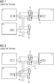
- FIG. 1 is the fundamental problem with the construction of functionally secure connections between connectable and disconnectable automation devices shown.
- the communication between a first automation device G1 and a second automation device G2 or between a third automation device G3 and the second automation device G2 is functionally safety-relevant.
- secure on the second programmable controller G2 Sensors and / or actuators are located, which should communicate via a secure channel with the first programmable controller G1 and the third programmable controller G3.
- the secure communication should also serve to reliably identify which devices are currently connected to each other.
- the second automation device G2 is allowed to perform certain actions as long as it is connected to the first automation device G1. For safety reasons, however, the same actions should be prohibited if the second automation device G2 is connected to the third automation device G3.
- the safety of automation devices for example, the following problem arises: An error in the use of the second programmable controller G2 by the programmable controllers G1, G3 must be recognized for reasons of functional safety with a high probability and lead to a safe state. For example, an error could occur in which the second automation device G2, which is connected to the first automation device G1, but it is due to a fault, a logical connection between the third automation device G3 and the second automation device G2 builds (see FIG. 2 ). An incorrect connection 20 has been erroneously established between the third automation device G3 and the second automation device G2.
- One hitherto common mechanism for detecting incorrectly constructed connections or for detecting addressing errors is the use of unique identifiers for the individual connections in the secure communication layer (eg "code name" in the case of Profisafe).
- the identifier "code name” does not provide the required error detection, which is desired for the case shown in a functionally secure communication layer fieldbus (as shown in the functionally safe communication layers shown in IEC 61874-3X).
- This is due to the fact that the identifier "code name” in the second automation device G2 can be visible from both other automation devices G1, G3, even if the automation devices are not coupled to the associated coupling points.
- an inventive automation system 1 is shown with a field bus FB.
- the first automation device G1 is a first coupling point S1 and the second automation device G2 is associated with a second coupling point S2.
- the second automation device G2 is docked in such a way that it has both a communication connection to the fieldbus FB and a communication link to an additional to the fieldbus FB between the first automation device G1 and the first coupling point S1 and the second coupling point S2 first point-to-point communication line 11 can establish a connection.
- a point-to-point communication line 11 is present in addition to the fieldbus FB between the first coupling point S1 and the second coupling point S2, as a result of which a first automation device G1 which can be coupled to and disconnected from the first coupling point S1 and to the second coupling point S2 on and decoupled second automation device G2 a pair relationship between on the field bus FB can be coupled and disconnected automation devices G1, G2 is present.
- the third coupling point S3 has a second point-to-point communication line 12 in addition to the fieldbus FB.
- This second point-to-point communication line 12 leads from the third coupling point S3 with a connector to the fourth coupling point S4.
- the second automation device G2 is coupled to the second coupling point S2, so may be located in the second automation device G2 second Connect point-to-point communication end point P2 via the additional point-to-point communication line 11 with a first point-to-point communication end point P1 arranged in the first automation device G1.
- a first test device PM1 which is designed to securely check on the basis of the additional communication via the first point-to-point communication line 11, whether the second automation device G2 is connected to the second coupling device S2 assigned to the first automation device G1.
- the third automation device G3 has a second test means PM2, which is configured to check securely whether the second automation device G2 is connected to the fourth coupling point S4.
- the second point-to-point communication line 12 is used.
- the test means PM1, PM2 further comprise means for carrying out a challenge-response method.
- An example of the challenge-response method is to use a sufficiently unique numerical value in the first automation device G1 and in the third automation device G3 (eg to generate N-bit random value).
- a random number generator RND is available.
- the generated random number is communicated to the second automation device G2 via the additionally introduced first point-to-point communication line 11.
- the second automation device G2 modifies the random value in a predetermined manner (eg bit-wise inversion or multiplication with an odd N-bit constant) and sends the result back.
- first automation device G1 or the third automation device G3 receives the expected return value, it can be concluded that a mechanical connection to the second automation device G2 has been established.
- Safety-related data can then be exchanged via the functionally reliable connection of the first automation device G1 to the second automation device G2 via the fieldbus FB.
- first functionally reliable fieldbus communication endpoint F1 and a second functionally reliable fieldbus communication endpoint F2 are available.
- the second automation device G2 has with the second functionally safe fieldbus communication endpoint F2 the corresponding counterpart for a functionally secure communication via the fieldbus FB.
- a functionally secure point-to-point communication is used.
- Functionally secure point-to-point communication can be achieved, for example, by a functionally secure IO-Link point-to-point link with a functionally secure protocol.
- the first automation device G1 has a first functionally secure point-to-point communication endpoint FP1 and the second automation device G1 has a second functionally secure point-to-point communication endpoint FP2.
- the third automation device G3 accordingly has a third functionally secure point-to-point communication endpoint FP3.
- the additional functionally secure point-to-point communication end points FP1 and FP2 are used for communication via the first point-to-point communication line 11.
Landscapes
- Engineering & Computer Science (AREA)
- Physics & Mathematics (AREA)
- General Physics & Mathematics (AREA)
- Automation & Control Theory (AREA)
- Computer Networks & Wireless Communication (AREA)
- Signal Processing (AREA)
- Small-Scale Networks (AREA)
Abstract
Description
- Die Erfindung betrifft ein Automatisierungssystem umfassend einen Feldbus mit mindestens drei Ankopplungsstellen, welche derart ausgestaltet sind, das ein automatisches An- und Abkoppeln von Automatisierungsgeräten an den Feldbus möglich ist, wobei die jeweils angekoppelten Automatisierungsgeräte ausgestaltet sind, untereinander funktional sichere Verbindungen über den Feldbus aufzubauen, wobei die dadurch erreichte funktionale Sicherheit zur Vermeidung von gefährlichen Fehlfunktionen durch Fehler dient.
- Im Sinne der Erfindung bedeutet funktionale Sicherheit, die Sicherheit für einen Teil eines Automatisierungssystems, der von einer korrekten Funktion der sicherheitsbezogenen Systeme und externen Einrichtungen zur Risikominimierung abhängt. Funktionale Sicherheit ist dann gegeben, wenn jedes Risiko über Sicherheitsfunktionen so abgesichert wird, dass die Maschine bzw. das dazugehörige Automatisierungssystem als sicher bezeichnet werden kann. Man spricht in diesem Fall von sicherheitsgerichteten Automatisierungssystemen.
- Funktionale Sicherheit wird beispielsweise bei einem Werkzeugwechsler benötigt. Beispielsweise arbeiten in einer Fertigungszelle mehrere Roboter, die abwechselnd mit mehreren Werkzeugen (z.B. Schweißzangen) arbeiten. Wenn ein Roboter ein Werkzeug greift, wird eine funktional sichere Verbindung zwischen dem Werkzeug und der Steuerung aufgebaut, die den Roboter kontrolliert. Selten benutzte Werkzeuge werden von den Robotern geteilt und können daher wechselweise an unterschiedlichen Robotern zum Einsatz kommen. Eine sichere Kommunikationsverbindung zum Werkzeug darf nur zur Steuerung des Roboters aufgebaut werden, der das Werkzeug auch gerade benutzt. Eine physische Separierung kommt nicht in Frage, da die Steuerung der Roboter untereinander kommunizieren muss.
- Die Ankopplungsstellen können beispielsweise in diesem Fall die Flansche der Roboter darstellen.
- Die
DE 10 2013 003 166 A1 offenbart ein Sicherheitsmodul für einen Feldbusteilnehmer und ein Automatisierungssystem. Zur Festlegung einer sicherheitsgerichteten Identifikationsadresse ist vorgesehen, in ein Gehäuse eines Sicherheitsmoduls eine Einstelleinrichtung anzuordnen. In dieser Einstelleinrichtung, beispielsweise einen DIL-Schalter, wird eine eindeutige Identifikationsadresse eingestellt. - Es ist Aufgabe der vorliegenden Erfindung, ein Automatisierungssystem mit einem steckplatzabhängigen Aufbau von funktional sicheren Feldbus-Verbindungen anzugeben, dabei aber auf eine Einstellvorrichtung, wie einen DIL-Schalter zu verzichten.
- Für das eingangs genannte Automatisierungssystem wird die Aufgabe dadurch gelöst, das zusätzlich zum Feldbus zwischen mindestens einer ersten Ankopplungsstelle und einer zweiten Ankopplungsstelle eine Punkt-zu-Punkt-Kommunikationsleitung vorhanden ist, wodurch für ein an die erste Ankopplungsstelle an- und abkoppelbares erstes Automatisierungsgerät und für einen an die zweite Ankopplungsstelle an- und abkoppelbares zweites Automatisierungsgerät eine Paarbeziehung zwischen den an den Feldbus an- und abkoppelbaren Automatisierungsgeräten vorhanden ist, wobei die an- und abkoppelbaren Automatisierungsgeräte jeweils einen Punkt-zu-Punkt-Kommunikationsendpunkt aufweisen, welche ausgestaltet sind, neben der Feldbuskommunikation zusätzlich eine Punkt-zu-Punkt-Kommunikation über die Punkt-zu-Punkt-Kommunikationsleitung aufzubauen und weiterhin weist mindestens eines der an- und abkoppelbaren Automatisierungsgeräte ein Prüfmittel auf, welches dazu ausgestaltet ist, anhand der durch die zusätzliche Punkt-zu-Punkt-Kommunikationsleitung möglichen zusätzlichen Kommunikation sicher zu prüfen, ob die gewünschte funktional sichere Verbindung zwischen den Automatisierungsgeräten aufgebaut wurde und ob sich auch das gewünschte Automatisierungsgerät am gegenüberliegenden Ende der Punkt-zu-Punkt-Kommunikationsleitung befindet, und nicht fälschlicherweise eine funktional sichere Verbindung zu einem Automatisierungsgerät aufgebaut wird, das sich an einer anderen Ankopplungsstelle befindet, welches nicht der Paarbeziehung entspricht.
- Vereinfacht gesagt wird erfindungsgemäß neben dem Feldbus bzw. neben einer Feldbuskommunikations-Leitung, eine zusätzliche Kommunikationsleitung zwischen den Automatisierungsgeräten angeordnet, wobei ein zusätzlicher Steckverbinder für das automatisierte Ankoppeln des Wechselgerätes an die Ankopplungsstelle vorhanden ist. Demnach könnte im gleichen Kabel der Feldbuskommunikationsleitung und am gleichen Stecker eine zusätzliche Kommunikationsleitung hinzugefügt werden, die funktional nur "Punkt-zu-Punkt"-Kommunikation erlaubt. Die Verwendung einer Punkt-zu-Punkt-Verbindung bewirkt, dass es kein Fehlerszenario für dieses Kommunikationsprotokoll gibt, bei dem ein vom Sender gesendetes Telegramm von einer anderen als den gewünschten Empfänger empfangen werden kann. Eine derartige Punkt-zu-Punkt-Kopplung kann so aufgebaut werden, dass über die zu einen Zeitpunkt X gegebene SteckerVerbindung, das erste Automatisierungsgerät mit dem zweiten Automatisierungsgerät sicher kommunizieren darf. Die zu dem Zeitpunkt X gegebene Steckerverbindung für die Punkt-zu-Punkt-Kommunikation gibt demnach vor, welche kommunikationstechnische mögliche Verbindung zustande kommen darf. So können die beiden Automatisierungsgeräte sicher prüfen, ob sie gerade wirklich miteinander verbunden sind oder nicht. Sobald diese Prüfung erfolgt ist, kann eine sichere Feldbusverbindung zwischen den Automatisierungsgeräten über den Feldbus genutzt werden.
- In einer weiteren Ausgestaltungsform sind vier Ankopplungsstellen vorhanden, und zusätzlich zum Feldbus zwischen einer dritten Ankopplungsstelle und einer vierten Ankopplungsstelle ist eine zweite Punkt-zu-Punkt-Kommunikationsleitung vorhanden, wodurch für ein an die dritte Ankopplungsstelle an- und abkoppelbares Automatisierungsgerät und für ein an die vierte Ankopplungsstelle an- und abkoppelbares Automatisierungsgerät eine weitere Paarbeziehung zwischen an den Feldbus an- und abkoppelbaren Automatisierungsgeräten vorhanden ist.
- In einer ersten Ausgestaltungsvariante weisen die Prüfmittel zusätzlich Mittel zum Durchführen eines Challenge-Response-Verfahrens auf. Eine sichere Prüfung der bestehenden Kommunikationsverbindung zwischen zwei an- und abkoppelbaren Automatisierungsgeräten kann dann mit einem Challenge-Response-Verfahren durchgeführt werden. Das erste Automatisierungsgerät formuliert dann mit den Mitteln zur Durchführung des Challenge-Response-Verfahrens zu jedem Zeitpunkt eine unterschiedliche Anfrage (Challenge), die von dem zweiten Automatisierungsgerät bzw. von dem Partner-Automatisierungsgerät aus der Paarbeziehung in geeigneter Weise beantwortet werden muss (Response), sobald die Steckverbindung hergestellt wird. Für eine neue Herstellung der Steckverbindung ändert das erste Automatisierungsgerät die Anfrage. Auf diese Weise ist sichergestellt, dass die Anfrage nicht in fehlerhafter Weise durch eine Speichernetzkomponente, z.B. Router, mithilfe einer veralteten Nachricht beantwortet werden kann.
- Bei dieser Ausgestaltungsvariante sind die erste Punkt-zu-Punkt-Kommunikationsleitung und die zweite Punkt-zu-Punkt-Kommunikationsleitung und die in dem Automatisierungsgeräten angeordneten entsprechenden Punkt-zu-Punkt-Kommunikationsendpunkte als eine standardisierte IO-Link Punkt-zu-Punkt-Kopplung ausgestaltet.
- Eine zweite Ausgestaltungsvariante schlägt vor, die erste Punkt-zu-Punkt-Kommunikationsleitung und die zweite Punkt-zu-Punkt-Kommunikationsleitung und die in den Automatisierungsgeräten angeordneten entsprechenden Punkt-zu-Punkt-Kommunikationsendpunkte als eine funktional sichere IO-Link Punkt-zu-Punkt-Kopplung mit einem funktional sicheren Protokoll auszugestalten. Dafür werden die Punkt-zu-Punkt-Kommunikationsendpunkte zusätzlich als funktional sichere Punkt-zu-Punkt-Kommunikationsendpunkte ausgestaltet.
- Weiterhin ist es ratsam, wenn die Automatisierungsgeräte für die funktional sichere Kommunikation funktional sichere Feldbus-Kommunikations-Endpunkte aufweisen.
- Insbesondere in Bezug auf Automatisierungsgeräte, welche als Werkzeugwechsler, Robotersysteme oder Spannrahmen ausgestaltet sind, ist es von Vorteil, wenn die Automatisierungsgeräte einem Handhabungs- und oder Bearbeitungssystem zugeordnet sind, und das zumindest ein Automatisierungsgerät als ein austauschbares Werkzeug mit einem Feldbusteilnehmer ausgestaltet ist, der für eine Ansteuerung von Aktoren auf dem Werkzeug ausgebildet ist.
- Die Zeichnung zeigt ein Ausführungsbeispiel der Erfindung, dabei zeigt die
- FIG 1
- ein Automatisierungssystem mit einem Feldbus und Ankopplungsstellen nach dem Stand der Technik,
- FIG 2
- das Automatisierungssystem nach
FIG 1 mit der Darstellung einer Falschverbindung, - FIG 3
- ein erfindungsgemäßes Automatisierungssystem mit zusätzlichen Punkt-zu-Punkt-Kommunikationsleitungen und
- FIG 4
- das erfindungsgemäße Automatisierungssystem mit zusätzlichen Punkt-zu-Punkt-Kommunikationsleitungen unter Benutzung einer funktional sicheren Punkt-zu-Punkt-Kopplung.
- Gemäß der
FIG 1 ist das grundsätzliche Problem mit dem Aufbau von funktional sicheren Verbindungen zwischen an- und abkoppelbaren Automatisierungsgeräten dargestellt. Die Kommunikation zwischen einem ersten Automatisierungsgerät G1 und einem zweiten Automatisierungsgeräte G2 bzw. zwischen einem dritten Automatisierungsgerät G3 und dem zweiten Automatisierungsgerät G2 sei funktional sicherheitsrelevant. Zum Beispiel können sich auf dem zweiten Automatisierungsgerät G2 sichere Sensoren und/oder Aktoren befinden, die über einen sicheren Kanal mit dem ersten Automatisierungsgerät G1 bzw. dem dritten Automatisierungsgerät G3 kommunizieren sollen. Die sichere Kommunikation soll auch dazu dienen, sicher zu erkennen, welche Geräte z.Z. miteinander verbunden sind. Zum Beispiel soll das zweite Automatisierungsgerät G2 bestimmte Aktionen ausführen dürfen, solange es mit dem ersten Automatisierungsgerät G1 verbunden ist. Dieselben Aktionen sollen aber aus Sicherheitsgründen verboten sein, wenn das zweite Automatisierungsgerät G2 mit dem dritten Automatisierungsgerät G3 verbunden ist. - Bei der Sicherheit von Automatisierungsgeräten ergibt sich beispielsweise folgendes Problem: Ein Fehler bei der Verwendung des zweiten Automatisierungsgerätes G2 durch die Automatisierungsgeräte G1, G3 muss aus Gründen der funktionalen Sicherheit mit einer hohen Wahrscheinlichkeit erkannt werden und zu einem sicheren Zustand führen. Beispielsweise könnte ein Fehler auftreten bei dem das zweite Automatisierungsgerät G2, welches mit dem ersten Automatisierungsgerät G1 verbunden ist, aber es wird aufgrund eines Fehlers eine logische Verbindung zwischen dem dritten Automatisierungsgerät G3 und dem zweiten Automatisierungsgerät G2 aufbaut (siehe hierzu
FIG 2 ). Zwischen dem dritten Automatisierungsgerät G3 und dem zweiten Automatisierungsgerät G2 ist irrtümlicherweise eine Falschverbindung 20 aufgebaut worden. Ein bisher gängiger Mechanismus zur Erkennung falsch aufgebauter Verbindungen oder zur Erkennung von Adressierfehlern ist die Verwendung eindeutiger Bezeichner für die einzelnen Verbindungen in der sicheren Kommunikationsschicht (z.B. "Codename" bei Profisafe). Im vorliegenden Fall bietet aber der Bezeichner "Codename" nicht die erforderliche Fehleraufdeckung, welche für den dargestellten Fall in einem funktional sicheren Kommunikations-Layer genutzten Feldbus (wie in der IEC 61874-3X dargestellten funktional sicheren Kommunikations-Layern) gewünscht ist. Dies liegt daran, dass der Bezeichner "Codename" im zweiten Automatisierungsgerät G2 von beiden anderen Automatisierungsgeräten G1, G3 sichtbar sein kann, auch wenn die Automatisierungsgeräte nicht an dem zugehörigen Ankopplungsstellen angekoppelt sind. Gesucht ist also eine Lösung, die den Aufbau einer falschen Verbindung sicher erkennt und mit einem einzelnen Bezeichner bzw. "Codename" für die Verbindung auskommt, der auch wechselweise verwendet werden kann. - Mit der
FIG 3 ist ein erfindungsgemäßes Automatisierungssystem 1 mit einem Feldbus FB gezeigt. Dem ersten Automatisierungsgerät G1 ist eine erste Ankopplungsstelle S1 und dem zweiten Automatisierungsgerät G2 ist eine zweite Ankopplungsstelle S2 zugeordnet. An der zweiten Ankopplungsstelle S2 ist das zweite Automatisierungsgerät G2 derart angedockt, dass es sowohl eine Kommunikationsverbindung zu dem Feldbus FB als auch eine Kommunikationsverbindung zu einer zusätzlich zu dem Feldbus FB zwischen dem ersten Automatisierungsgerät G1 und der ersten Ankopplungsstelle S1 bzw. der zweiten Ankopplungsstelle S2 verlegten ersten Punkt-zu-Punkt-Kommunikationsleitung 11 eine Verbindung aufbauen kann. Es ist demnach zusätzlich zum Feldbus FB zwischen der ersten Ankopplungsstelle S1 und der zweiten Ankopplungsstelle S2 eine Punkt-zu-Punkt-Kommunikationsleitung 11 vorhanden, wodurch für ein an die erste Ankopplungsstelle S1 an- und abkoppelbares erstes Automatisierungsgerät G1 und für ein an die zweite Ankopplungsstelle S2 an- und abkoppelbares zweites Automatisierungsgerät G2 eine Paarbeziehung zwischen an dem Feldbus FB an- und abkoppelbaren Automatisierungsgeräten G1, G2 vorhanden ist. - Für das sichere Erkennen eines Vorhandenseins eines Automatisierungsgerätes G2 an der vierten Ankopplungsstelle S4 weist die dritte Ankopplungsstelle S3 zusätzlich zu dem Feldbus FB eine zweite Punkt-zu-Punkt-Kommunikationsleitung 12 auf. Diese zweite Punkt-zu-Punkt-Kommunikationsleitung 12 führt von der dritten Ankopplungsstelle S3 mit einem Steckverbinder zu der vierten Ankopplungsstelle S4.
- Wenn nun das zweite Automatisierungsgerät G2 an die zweite Ankopplungsstelle S2 angekoppelt wird, so kann sich ein in dem zweiten Automatisierungsgerät G2 befindliche zweiter Punkt-zu-Punkt-Kommunikationsendpunkt P2 über die zusätzliche Punkt-zu-Punkt-Kommunikationsleitung 11 mit einem im ersten Automatisierungsgerät G1 angeordneten ersten Punkt-zu-Punkt-Kommunikationsendpunkt P1 verbinden. Über ein erstes Prüfmittel PM1, welches ausgestaltet ist, anhand der zusätzlichen Kommunikation über die erste Punkt-zu-Punkt-Kommunikationsleitung 11 sicher zu prüfen, ob an der dem ersten Automatisierungsgerät G1 zugeordneten zweiten Ankopplungsstelle S2 das zweite Automatisierungsgerät G2 angeschlossen ist.
- Auch das dritte Automatisierungsgerät G3 weist ein zweites Prüfmittel PM2 auf, welches ausgestaltet ist, sicher zu prüfen, ob an der vierten Ankopplungsstelle S4 das zweite Automatisierungsgerät G2 angeschlossen ist. Für die sichere Prüfung wird die zweite Punkt-zu-Punkt-Kommunikationsleitung 12 genutzt.
- In dem Ausführungsbeispiel gemäß
FIG 3 weisen die Prüfmittel PM1, PM2 weiterhin Mittel zur Durchführung eines Challenge-Response-Verfahrens auf. Ein beispielhaftes auf das Challenge-Response-Verfahren besteht darin, in dem ersten Automatisierungsgerät G1 und in dem dritten Automatisierungsgerät G3 einen hinreichend eindeutigen Zahlenwert zu nutzen (z.B. N-Bit-Zufallswert zu generieren). Hierzu steht ein Zufallsgenerator RND zur Verfügung. Die generierte Zufallszahl wird dem zweiten Automatisierungsgerät G2 über die zusätzlich eingeführte erste Punkt-zu-Punkt-Kommunikationsleitung 11 mitgeteilt. Das zweite Automatisierungsgerät G2 modifiziert den Zufallswert in einer vorher festgelegten Weise (z.B. bitweises Invertieren oder Multiplikation mit einer ungeraden N-Bit-Konstante) und sendet das Ergebnis zurück. Erhält das erste Automatisierungsgerät G1 bzw. das dritte Automatisierungsgerät G3 den erwarteten Rückgabewert, kann gefolgert werden, dass eine mechanische Verbindung zu dem zweiten Automatisierungsgerät G2 hergestellt ist. Über die funktional sichere Verbindung des ersten Automatisierungsgerätes G1 zu dem zweiten Automatisierungsgerät G2 über den Feldbus FB können dann sicherheitsbezogene Daten ausgetauscht werden. Hierfür stehen in dem ersten Automatisierungsgerät G1 und in dem zweiten Automatisierungsgerät G2 jeweils ein erster funktional sicherer Feldbuskommunikationsendpunkt F1 und ein zweiter funktional sicherer Feldbuskommunikationsendpunkt F2 zur Verfügung. Das zweite Automatisierungsgerät G2 weist mit dem zweiten funktional sicheren Feldbuskommunikationsendpunkt F2 das entsprechende Gegenstück für eine funktional sichere Kommunikation über den Feldbus FB auf. Mittels der genannten funktional sicheren Feldbuskommunikationsendpunkte F1, F2, F3 kann nun eine funktional sichere Kommunikation 21 zwischen den beiden Automatisierungsgeräten G1 und G2 geführt werden. - Gemäß
FIG 4 ist eine Ausgestaltungsvariante gezeigt, wobei für die Punkt-zu-Punkt-Kommunikation eine funktional sichere Punkt-zu-Punkt-Kommunikation eingesetzt wird. Eine funktional sichere Punkt-zu-Punkt-Kommunikation kann man beispielsweise durch eine funktional sichere IO-Link-Punkt-zu-Punkt-Kopplung mit einem funktional sicheren Protokoll erreichen. Für diese funktional sichere Punkt-zu-Punkt-Kommunikation weist das erste Automatisierungsgerät G1 einen ersten funktional sicheren Punkt-zu-Punkt-Kommunikationsendpunkt FP1 und das zweite Automatisierungsgerät G1 einen zweiten funktional sicheren Punkt-zu-Punkt-Kommunikationsendpunkt FP2 auf. Das dritte Automatisierungsgerät G3 weist entsprechend einen dritten funktional sicheren Punkt-zu-Punkt-Kommunikationsendpunkt FP3 auf. Für eine funktional sichere zusätzliche Kommunikation zwischen dem ersten Automatisierungsgerät G1 und dem zweiten Automatisierungsgerät G2 werden für die Kommunikation über die erste Punkt-zu-Punkt-Kommunikationsleitung 11 die zusätzlichen funktional sicheren Punkt-zu-Punkt-Kommunikationsendpunkte FP1 und FP2 genutzt.
Claims (7)
- Automatisierungssystem (1) umfassend
einen Feldbus (FB) mit mindestens drei Ankopplungsstellen (S1, S2, S3), welche derart ausgestaltet sind, dass ein automatisches An- und Abkoppeln von Automatisierungsgeräten (G1, G2, G3) an den Feldbus (FB) möglich ist, wobei die jeweils angekoppelten Automatisierungsgeräte (G1, G2, G3) ausgestaltet sind, untereinander funktional sichere Verbindungen über den Feldbus (FB) auf zu bauen, wobei die dadurch erreichte funktionale Sicherheit zur Vermeidung von gefährlichen Fehlfunktionen durch Fehler dient,
dadurch gekennzeichnet, dass zusätzlich zum Feldbus (FB) zwischen mindestens einer ersten Ankopplungsstelle (S1) und einer zweiten Ankopplungsstelle (S2) eine Punkt-zu-Punkt-Kommunikationsleitung (11) vorhanden ist, wodurch für ein an die erste Ankopplungsstelle (S1) an- und abkoppelbares erstes Automatisierungsgerät (G1) und für ein an die zweite Ankopplungsstelle (S2) an- und abkoppelbares zweites Automatisierungsgerät (G2) eine Paarbeziehung zwischen an den Feldbus (FB) an- und abkoppelbaren Automatisierungsgeräten (G1, G2, G3) vorhanden ist, wobei die an- und abkoppelbaren Automatisierungsgeräte (G1, G2, G3) jeweils einen Punkt-zu-Punkt-Kommunikations-Endpunkt (P1,P2,P3) aufweisen, welche ausgestaltet sind, neben der Feldbuskommunikation zusätzlich eine Punkt-zu-Punkt-Kommunikation über die Punkt-zu-Punkt-Kommunikationsleitung (11) aufzubauen und weiterhin weist mindestens eines der an- und abkoppelbaren Automatisierungsgeräte (G1, G2, G3) ein Prüfmittel (PM1, PM2) auf, welches dazu ausgestaltet ist, an Hand der durch die zusätzliche Punkt-zu-Punkt-Kommunikationsleitung (11) möglichen zusätzlichen Kommunikation sicher zu prüfen, ob die gewünschte funktional sichere Verbindung zwischen den Automatisierungsgeräten (G1, G2, G3) aufgebaut wurde und ob sich auch das gewünschte Automatisierungsgerät (G1, G2, G3) am gegenüberliegenden Ende der Punkt-zu-Punkt-Kommunikationsleitung (11) befindet, und nicht fälschlicherweise eine funktional sichere Verbindung zu einem Automatisierungsgerät (G1, G2, G3) aufgebaut wird, das sich an einer anderen Ankopplungsstelle (S3) befindet, welches nicht der Paarbeziehung entspricht. - Automatisierungssystem (1) nach Anspruch 1, wobei vier Ankopplungsstellen (S1, S2, S3, S4) vorhanden sind, und zusätzlich zum Feldbus (FB) zwischen einer dritten Ankopplungsstelle (S3) und einer vierten Ankopplungsstelle (S4) eine zweite Punkt-zu-Punkt-Kommunikationsleitung (12) vorhanden ist, wodurch für ein an die dritte Ankopplungsstelle (S1) an- und abkoppelbares Automatisierungsgerät (G1, G2, G3) und für ein an die vierte Ankopplungsstelle (S4) an- und abkoppelbares Automatisierungsgerät (G1, G2, G3) eine weitere Paarbeziehung zwischen an den Feldbus (FB) an- und abkoppelbaren Automatisierungsgeräten (G1, G2, G3) vorhanden ist.
- Automatisierungssystem (1) nach Anspruch 1 oder 2, wobei die Prüfmittel (PM1, PM2) Mittel zum Durchführen eines Challenge-Response-Verfahrens aufweisen.
- Automatisierungssystem (1) nach Anspruch 2 oder 3, wobei die erste Punkt-zu-Punkt-Kommunikationsleitung (11) und die zweite Punkt-zu-Punkt-Kommunikationsleitung (12) und die in den Automatisierungsgeräten (G1, G2, G3) angeordneten entsprechenden Punkt-zu-Punkt-Kommunikations-Endpunkte (P1, P2) als eine standardisierte IO-Link Punkt-zu-Punkt-Kopplung ausgestaltet ist.
- Automatisierungssystem (1) nach Anspruch 2 oder 3, wobei die erste Punkt-zu-Punkt-Kommunikationsleitung (11) und die zweite Punkt-zu-Punkt-Kommunikationsleitung (12) und die in den Automatisierungsgeräten (G1, G2, G3) angeordneten entsprechenden Punkt-zu-Punkt-Kommunikations-Endpunkte (P1, P2) als eine funktional sichere IO-Link Punkt-zu-Punkt-Kopplung mit einem funktional sicheren Protokoll ausgestaltet ist.
- Automatisierungssystem (1) nach einem der Ansprüche 1 bis 5, wobei die Automatisierungsgeräte (G1, G2, G3) funktional sichere Feldbus-Kommunikations-Endpunkte aufweisen.
- Automatisierungssystem nach einem der vorhergehenden Ansprüche,
dadurch gekennzeichnet, dass die Automatisierungsgeräte (G1, G2, G3) einem Handhabungs- und/oder Bearbeitungssystem zugeordnet sind, und das zumindest ein Automatisierungsgerät (G1, G2, G3) als ein austauschbares Werkzeug mit einen Feldbusteilnehmer ausgestaltet ist, der für eine Ansteuerung von Aktoren auf dem Werkzeug ausgebildet ist.
Priority Applications (3)
| Application Number | Priority Date | Filing Date | Title |
|---|---|---|---|
| EP17165756.2A EP3388902B1 (de) | 2017-04-10 | 2017-04-10 | Sicherheitsgerichtetes automatisierungssystem |
| CN201810238484.1A CN108693813B (zh) | 2017-04-10 | 2018-03-21 | 安全导向的自动化系统 |
| US15/948,454 US10599117B2 (en) | 2017-04-10 | 2018-04-09 | Safety-oriented automation system |
Applications Claiming Priority (1)
| Application Number | Priority Date | Filing Date | Title |
|---|---|---|---|
| EP17165756.2A EP3388902B1 (de) | 2017-04-10 | 2017-04-10 | Sicherheitsgerichtetes automatisierungssystem |
Publications (3)
| Publication Number | Publication Date |
|---|---|
| EP3388902A1 true EP3388902A1 (de) | 2018-10-17 |
| EP3388902B1 EP3388902B1 (de) | 2026-02-18 |
| EP3388902C0 EP3388902C0 (de) | 2026-02-18 |
Family
ID=58664453
Family Applications (1)
| Application Number | Title | Priority Date | Filing Date |
|---|---|---|---|
| EP17165756.2A Active EP3388902B1 (de) | 2017-04-10 | 2017-04-10 | Sicherheitsgerichtetes automatisierungssystem |
Country Status (3)
| Country | Link |
|---|---|
| US (1) | US10599117B2 (de) |
| EP (1) | EP3388902B1 (de) |
| CN (1) | CN108693813B (de) |
Cited By (1)
| Publication number | Priority date | Publication date | Assignee | Title |
|---|---|---|---|---|
| EP4502739A1 (de) * | 2023-07-31 | 2025-02-05 | Siemens Aktiengesellschaft | Verfahren zum überprüfen einer funktionstüchtigkeit einer schaltungsanordnung für eine steuerung einer maschine mittels der schaltungsanordnung, computerprogrammprodukt, computerlesbares speichermedium sowie schaltungsanordnung |
Families Citing this family (1)
| Publication number | Priority date | Publication date | Assignee | Title |
|---|---|---|---|---|
| EP3716568A1 (de) * | 2019-03-28 | 2020-09-30 | Siemens Aktiengesellschaft | Funktional-sichere verbindungsidentifizierung für eine m2m kommunikation |
Citations (5)
| Publication number | Priority date | Publication date | Assignee | Title |
|---|---|---|---|---|
| US20040158713A1 (en) * | 2003-01-28 | 2004-08-12 | Tom Aneweer | Process control system with an embedded safety system |
| EP1933497A1 (de) * | 2006-12-12 | 2008-06-18 | Abb Research Ltd. | Verfahren und Server zum Genehmigen kritischer Befehle |
| US20090105849A1 (en) * | 1997-08-21 | 2009-04-23 | Fieldbus Foundation | System and method for implementing safety instrumented systems in a fieldbus architecture |
| DE102013003166A1 (de) | 2013-02-26 | 2014-08-28 | Festo Ag & Co. Kg | Sicherheitsmodul für einen Feldbusteilnehmer und Automatisierungssystem |
| US20150229654A1 (en) * | 2014-02-10 | 2015-08-13 | Stmicroelectronics International N.V. | Secured transactions in internet of things embedded systems networks |
Family Cites Families (7)
| Publication number | Priority date | Publication date | Assignee | Title |
|---|---|---|---|---|
| US6014612A (en) * | 1997-10-02 | 2000-01-11 | Fisher Controls International, Inc. | Remote diagnostics in a process control network having distributed control functions |
| US7027893B2 (en) * | 2003-08-25 | 2006-04-11 | Ati Industrial Automation, Inc. | Robotic tool coupler rapid-connect bus |
| DE102008050102B4 (de) * | 2008-10-06 | 2010-11-04 | Phoenix Contact Gmbh & Co. Kg | Kommunikationsentität zur Kommunikation über ein busorientiertes Kommunikationsnetzwerk |
| US8948782B2 (en) * | 2012-12-21 | 2015-02-03 | Qualcomm Incorporated | Proximity determination based on distance ratios |
| US9903940B2 (en) * | 2013-12-30 | 2018-02-27 | Qualcomm Incorporated | Entrusted device localization scheme using ultrasound signatures |
| GB2535839B (en) * | 2015-01-08 | 2021-06-09 | Fisher Rosemount Systems Inc | Apparatus and methods to communicatively couple field devices to controllers in a process control system |
| CN204870600U (zh) * | 2015-04-20 | 2015-12-16 | 南京金龙新能源汽车研究院有限公司 | 一种电动汽车智能整车控制器 |
-
2017
- 2017-04-10 EP EP17165756.2A patent/EP3388902B1/de active Active
-
2018
- 2018-03-21 CN CN201810238484.1A patent/CN108693813B/zh active Active
- 2018-04-09 US US15/948,454 patent/US10599117B2/en active Active
Patent Citations (5)
| Publication number | Priority date | Publication date | Assignee | Title |
|---|---|---|---|---|
| US20090105849A1 (en) * | 1997-08-21 | 2009-04-23 | Fieldbus Foundation | System and method for implementing safety instrumented systems in a fieldbus architecture |
| US20040158713A1 (en) * | 2003-01-28 | 2004-08-12 | Tom Aneweer | Process control system with an embedded safety system |
| EP1933497A1 (de) * | 2006-12-12 | 2008-06-18 | Abb Research Ltd. | Verfahren und Server zum Genehmigen kritischer Befehle |
| DE102013003166A1 (de) | 2013-02-26 | 2014-08-28 | Festo Ag & Co. Kg | Sicherheitsmodul für einen Feldbusteilnehmer und Automatisierungssystem |
| US20150229654A1 (en) * | 2014-02-10 | 2015-08-13 | Stmicroelectronics International N.V. | Secured transactions in internet of things embedded systems networks |
Cited By (1)
| Publication number | Priority date | Publication date | Assignee | Title |
|---|---|---|---|---|
| EP4502739A1 (de) * | 2023-07-31 | 2025-02-05 | Siemens Aktiengesellschaft | Verfahren zum überprüfen einer funktionstüchtigkeit einer schaltungsanordnung für eine steuerung einer maschine mittels der schaltungsanordnung, computerprogrammprodukt, computerlesbares speichermedium sowie schaltungsanordnung |
Also Published As
| Publication number | Publication date |
|---|---|
| EP3388902B1 (de) | 2026-02-18 |
| CN108693813A (zh) | 2018-10-23 |
| US10599117B2 (en) | 2020-03-24 |
| EP3388902C0 (de) | 2026-02-18 |
| US20180292796A1 (en) | 2018-10-11 |
| CN108693813B (zh) | 2023-11-07 |
Similar Documents
| Publication | Publication Date | Title |
|---|---|---|
| EP1923759B1 (de) | Verfahren und System zur sicheren Datenübertragung | |
| EP4235323B1 (de) | Verfahren und vorrichtung zur automatischen validierung von sicherheitsfunktionen an einem modular aufgebauten sicherheitssystem | |
| DE102007050708B4 (de) | System zum Betreiben wenigstens eines nicht-sicherheitskritischen und wenigstens eines sicherheitskritischen Prozesses | |
| DE102014110017A1 (de) | Steuer- und Datenübertragungssystem, Gateway-Modul, E/A-Modul und Verfahren zur Prozesssteuerung | |
| DE102011107318A1 (de) | Verfahren zur Konfigurierung eines Kommunikationsschnittstellenmoduls in einem Steuerungs- oder Automatisierungssystem | |
| EP2981868A1 (de) | Steuer- und datenübertragungsanlage, prozesseinrichtung und verfahren zur redundanten prozesssteuerung mit dezentraler redundanz | |
| EP1068561B1 (de) | Fehlersicheres datenübertragungssystem und -verfahren | |
| DE102008044018A1 (de) | Verfahren zum Bestimmen einer Sicherheitsstufe und Sicherheitsmanager | |
| DE102014111361A1 (de) | Verfahren zum Betreiben einer Sicherheitssteuerung und Automatisierungsnetzwerk mit einer solchen Sicherheitssteuerung | |
| EP3745217B1 (de) | Vorrichtung zum überwachen einer datenverarbeitung und - übertragung in einem sicherheitssystems | |
| DE102015122066A1 (de) | Fehlersicheres Modul zum Anschluss an einen Feldbuskoppler, Feldbuskoppler, System und Verfahren zum Konfigurieren eines derartigen fehlersicheren Moduls | |
| EP2375636A1 (de) | Vorrichtung und Verfahren zum Konfigurieren eines Bussystems | |
| DE102016222938B4 (de) | Sicherheitsmodul für ein Automatisierungssystem, Verfahren zum Betreiben eines Sicherheitsmoduls in einem Automatisierungssystem sowie Automatisierungssystem | |
| EP3388902B1 (de) | Sicherheitsgerichtetes automatisierungssystem | |
| EP3470939B1 (de) | Verfahren und system zum überwachen der sicherheitsintegrität einer durch ein sicherheitssystem bereitgestellten sicherheitsfunktion | |
| EP3470937B1 (de) | Verfahren und vorrichtungen zum überwachen der reaktionszeit einer durch ein sicherheitssystem bereitgestellten sicherheitsfunktion | |
| EP3484127A1 (de) | Verfahren und vorrichtung zur sicheren vergabe von adressen an module in einem netzwerk, adressierungseinrichtung, computerprogrammprodukt und industrielle anlage | |
| EP3599525B1 (de) | Verfahren zur sicheren datenkommunikation an einer numerisch gesteuerten werkzeugmaschine | |
| EP3267271A1 (de) | Automatisierungssystem und verfahren zum betrieb | |
| EP3388901B1 (de) | Sicherheitsgerichtetes automatisierungssystem | |
| EP3869331A1 (de) | Verfahren zur anpassung von f-adressen und anlagenmodul | |
| EP2741451A1 (de) | Verfahren zum Anbinden eines Hardwaremoduls an einen Feldbus | |
| EP1921525B1 (de) | Verfahren zum Betrieb einer sicherheitsgerichteten Anlage | |
| EP2950174A1 (de) | Verfahren und Vorrichtung zum sicheren Überprüfen eines Zustandes zweier Einrichtungen | |
| EP3478541B1 (de) | Sicherheitseinrichtung und verfahren zum betreiben eines systems |
Legal Events
| Date | Code | Title | Description |
|---|---|---|---|
| PUAI | Public reference made under article 153(3) epc to a published international application that has entered the european phase |
Free format text: ORIGINAL CODE: 0009012 |
|
| STAA | Information on the status of an ep patent application or granted ep patent |
Free format text: STATUS: THE APPLICATION HAS BEEN PUBLISHED |
|
| AK | Designated contracting states |
Kind code of ref document: A1 Designated state(s): AL AT BE BG CH CY CZ DE DK EE ES FI FR GB GR HR HU IE IS IT LI LT LU LV MC MK MT NL NO PL PT RO RS SE SI SK SM TR |
|
| AX | Request for extension of the european patent |
Extension state: BA ME |
|
| STAA | Information on the status of an ep patent application or granted ep patent |
Free format text: STATUS: REQUEST FOR EXAMINATION WAS MADE |
|
| 17P | Request for examination filed |
Effective date: 20190404 |
|
| RBV | Designated contracting states (corrected) |
Designated state(s): AL AT BE BG CH CY CZ DE DK EE ES FI FR GB GR HR HU IE IS IT LI LT LU LV MC MK MT NL NO PL PT RO RS SE SI SK SM TR |
|
| STAA | Information on the status of an ep patent application or granted ep patent |
Free format text: STATUS: EXAMINATION IS IN PROGRESS |
|
| 17Q | First examination report despatched |
Effective date: 20210329 |
|
| REG | Reference to a national code |
Ref country code: DE Free format text: PREVIOUS MAIN CLASS: G05B0009020000 Ref country code: DE Ref legal event code: R079 Ref document number: 502017017220 Country of ref document: DE Free format text: PREVIOUS MAIN CLASS: G05B0009020000 Ipc: G05B0019048000 |
|
| GRAP | Despatch of communication of intention to grant a patent |
Free format text: ORIGINAL CODE: EPIDOSNIGR1 |
|
| STAA | Information on the status of an ep patent application or granted ep patent |
Free format text: STATUS: GRANT OF PATENT IS INTENDED |
|
| RIC1 | Information provided on ipc code assigned before grant |
Ipc: G05B 19/048 20060101AFI20250919BHEP Ipc: G05B 9/02 20060101ALI20250919BHEP |
|
| INTG | Intention to grant announced |
Effective date: 20251013 |
|
| GRAS | Grant fee paid |
Free format text: ORIGINAL CODE: EPIDOSNIGR3 |
|
| GRAA | (expected) grant |
Free format text: ORIGINAL CODE: 0009210 |
|
| STAA | Information on the status of an ep patent application or granted ep patent |
Free format text: STATUS: THE PATENT HAS BEEN GRANTED |
|
| AK | Designated contracting states |
Kind code of ref document: B1 Designated state(s): AL AT BE BG CH CY CZ DE DK EE ES FI FR GB GR HR HU IE IS IT LI LT LU LV MC MK MT NL NO PL PT RO RS SE SI SK SM TR |
|
| REG | Reference to a national code |
Ref country code: CH Ref legal event code: F10 Free format text: ST27 STATUS EVENT CODE: U-0-0-F10-F00 (AS PROVIDED BY THE NATIONAL OFFICE) Effective date: 20260218 Ref country code: GB Ref legal event code: FG4D Free format text: NOT ENGLISH |
|
| REG | Reference to a national code |
Ref country code: IE Ref legal event code: FG4D Free format text: LANGUAGE OF EP DOCUMENT: GERMAN |
|
| U01 | Request for unitary effect filed |
Effective date: 20260218 |
|
| U07 | Unitary effect registered |
Designated state(s): AT BE BG DE DK EE FI FR IT LT LU LV MT NL PT RO SE SI Effective date: 20260223 |