EP3599512A1 - Heater, heating device, fixing device, and image forming apparatus - Google Patents
Heater, heating device, fixing device, and image forming apparatus Download PDFInfo
- Publication number
- EP3599512A1 EP3599512A1 EP19182372.3A EP19182372A EP3599512A1 EP 3599512 A1 EP3599512 A1 EP 3599512A1 EP 19182372 A EP19182372 A EP 19182372A EP 3599512 A1 EP3599512 A1 EP 3599512A1
- Authority
- EP
- European Patent Office
- Prior art keywords
- heater
- layer
- electrode
- base layer
- insulation layer
- Prior art date
- Legal status (The legal status is an assumption and is not a legal conclusion. Google has not performed a legal analysis and makes no representation as to the accuracy of the status listed.)
- Granted
Links
Images





Classifications
-
- G—PHYSICS
- G03—PHOTOGRAPHY; CINEMATOGRAPHY; ANALOGOUS TECHNIQUES USING WAVES OTHER THAN OPTICAL WAVES; ELECTROGRAPHY; HOLOGRAPHY
- G03G—ELECTROGRAPHY; ELECTROPHOTOGRAPHY; MAGNETOGRAPHY
- G03G15/00—Apparatus for electrographic processes using a charge pattern
- G03G15/20—Apparatus for electrographic processes using a charge pattern for fixing, e.g. by using heat
- G03G15/2003—Apparatus for electrographic processes using a charge pattern for fixing, e.g. by using heat using heat
- G03G15/2014—Apparatus for electrographic processes using a charge pattern for fixing, e.g. by using heat using heat using contact heat
- G03G15/2039—Apparatus for electrographic processes using a charge pattern for fixing, e.g. by using heat using heat using contact heat with means for controlling the fixing temperature
-
- G—PHYSICS
- G03—PHOTOGRAPHY; CINEMATOGRAPHY; ANALOGOUS TECHNIQUES USING WAVES OTHER THAN OPTICAL WAVES; ELECTROGRAPHY; HOLOGRAPHY
- G03G—ELECTROGRAPHY; ELECTROPHOTOGRAPHY; MAGNETOGRAPHY
- G03G15/00—Apparatus for electrographic processes using a charge pattern
- G03G15/20—Apparatus for electrographic processes using a charge pattern for fixing, e.g. by using heat
- G03G15/2003—Apparatus for electrographic processes using a charge pattern for fixing, e.g. by using heat using heat
- G03G15/2014—Apparatus for electrographic processes using a charge pattern for fixing, e.g. by using heat using heat using contact heat
- G03G15/2053—Structural details of heat elements, e.g. structure of roller or belt, eddy current, induction heating
-
- G—PHYSICS
- G03—PHOTOGRAPHY; CINEMATOGRAPHY; ANALOGOUS TECHNIQUES USING WAVES OTHER THAN OPTICAL WAVES; ELECTROGRAPHY; HOLOGRAPHY
- G03G—ELECTROGRAPHY; ELECTROPHOTOGRAPHY; MAGNETOGRAPHY
- G03G15/00—Apparatus for electrographic processes using a charge pattern
- G03G15/80—Details relating to power supplies, circuits boards, electrical connections
-
- G—PHYSICS
- G03—PHOTOGRAPHY; CINEMATOGRAPHY; ANALOGOUS TECHNIQUES USING WAVES OTHER THAN OPTICAL WAVES; ELECTROGRAPHY; HOLOGRAPHY
- G03G—ELECTROGRAPHY; ELECTROPHOTOGRAPHY; MAGNETOGRAPHY
- G03G2215/00—Apparatus for electrophotographic processes
- G03G2215/20—Details of the fixing device or porcess
- G03G2215/2003—Structural features of the fixing device
- G03G2215/2016—Heating belt
- G03G2215/2019—Heating belt the belt not heating the toner or medium directly, e.g. heating a heating roller
-
- G—PHYSICS
- G03—PHOTOGRAPHY; CINEMATOGRAPHY; ANALOGOUS TECHNIQUES USING WAVES OTHER THAN OPTICAL WAVES; ELECTROGRAPHY; HOLOGRAPHY
- G03G—ELECTROGRAPHY; ELECTROPHOTOGRAPHY; MAGNETOGRAPHY
- G03G2215/00—Apparatus for electrophotographic processes
- G03G2215/20—Details of the fixing device or porcess
- G03G2215/2003—Structural features of the fixing device
- G03G2215/2016—Heating belt
- G03G2215/2035—Heating belt the fixing nip having a stationary belt support member opposing a pressure member
Definitions
- Embodiments of the present disclosure generally relate to a heater, a heating device, a fixing device and an image forming apparatus.
- a laminated heater having a planar resistive heat generator is known as a heater used for a drying device to dry ink on a sheet or a fixing device to fix toner on the sheet by heat in an image forming apparatus such as a printer and a copier.
- the laminated heater generates heat when power is supplied to the resistive heat generator. Therefore, the laminated heater includes an electrode to which a connector is electrically connected to supply power from the power supply.
- JP-2014-109754-A discloses a configuration of the connector connected to the electrode of the laminated heater, in which the laminated heater is sandwiched from the front side and the back side thereof, and a contact terminal of the connector presses against the electrode of the laminated heater.
- the laminated heater has an issue that variation in contact pressure of the contact terminal pressed against the electrode causes an application of the contact pressure stronger than necessary contact pressure to the electrode, or conversely, shortage of the contact pressure.
- JP-2014-109754-A proposes a configuration in which the contact terminal is movable relative to the housing of the connector.
- the heater includes an electrode, a heat generator, and a plate having a portion corresponding to the electrode thinner than a portion corresponding to the heat generator.
- the present disclosure enables to reduce the variation in the contact pressure of the contact terminal with respect to the electrode and set the contact pressure to an appropriate value, that is, within an appropriate range.
- FIG. 1 is a schematic diagram illustrating a configuration of an image forming apparatus according to an embodiment of the present disclosure.
- the image forming apparatus 100 illustrated in FIG. 1 includes four image forming units 1Y, 1M, 1C, and 1Bk detachably attached to an apparatus body thereof.
- the image forming units 1Y, 1M, 1C, and 1Bk have the same configuration except for containing different color developers, i.e., yellow (Y), magenta (M), cyan (C), and black (Bk) toners, respectively, corresponding to decomposed color separation components of full-color images.
- each of the image forming units 1Y, 1M, 1C, and 1Bk includes: a photoconductor 2 in a drum-like shape as an image bearer; a charger 3 to charge a surface of the photoconductor 2; a developing device 4 configured to form a toner image by supplying toner, as a developer, to a surface of the photoconductor 2; and a cleaner 5 to clean the surface of the photoconductor 2.
- the image forming apparatus 100 further includes an exposure device 6 to expose the surface of each photoconductor 2 to form an electrostatic latent image, a sheet feeder 7 to supply a sheet P as a recording medium, a transfer device 8 to transfer the toner image formed on the each photoconductor 2 onto the sheet P, a fixing device 9 to fix the transferred toner image onto the sheet P, and an output device 10 to eject the sheet P outside the image forming apparatus 100.
- the transfer device 8 includes: an intermediate transfer belt 11 in the form of an endless belt stretched taut with multiple rollers, as an intermediate transferor; four primary transfer rollers 12 each as a primary transferor to transfer the toner image formed on each photoconductor 2 onto the intermediate transfer belt 11; and a secondary transfer roller 13 as a secondary transferor to transfer the toner image transferred onto the intermediate transfer belt 11 onto the sheet P.
- the primary transfer rollers 12 are in contact with the respective photoconductors 2 via the intermediate transfer belt 11. Therefore, the intermediate transfer belt 11 is in contact with the respective photoconductors 2, thus forming primary transfer nips therebetween.
- the secondary transfer roller 13 contacts, via the intermediate transfer belt 11, one of the plurality of rollers around which the intermediate transfer belt 11 is stretched. Thus, the secondary transfer nip is formed between the secondary transfer roller 13 and the intermediate transfer belt 11.
- a sheet conveyance path 14 is formed through which the sheet P fed from the sheet feeder 7 is conveyed.
- a timing roller pair 15 is disposed on the sheet conveyance path 14 on the way from the sheet feeder 7 to the secondary transfer nip (the secondary transfer roller 13).
- the photoconductors 2 are each driven to rotate clockwise in FIG. 1 and the surfaces thereof are uniformly charged to a high potential by the respective chargers 3.
- the exposure device 6 exposes the surface of the photoconductor 2.
- the developing device 4 supplies toner to the electrostatic latent image, thereby developing the latent image into the toner image on each of the photoconductors 2.
- the toner image on each of the photoconductors 2 reaches the primary transfer nip at each of the primary transfer rollers 12 in accordance with rotation of each of the photoconductors 2 and is sequentially transferred and superimposed onto the intermediate transfer belt 11 that is driven to rotate counterclockwise in FIG. 1 .
- the toner image transferred onto the intermediate transfer belt 11 reaches the secondary transfer nip at the secondary transfer roller 13 and is transferred onto the conveyed sheet P at the secondary transfer nip.
- the sheet P is fed from the sheet feeder 7.
- the timing roller pair 15 temporarily stops the sheet P fed from the sheet feeder 7 and conveys the sheet P to the secondary transfer nip, timed to coincide with the toner image on the intermediate transfer belt 11. Thus, a full-color toner image is formed on the sheet P.
- each of cleaners 5 removes residual toner on each of the photoconductors 2.
- the sheet P transferred the toner image is conveyed to the fixing device 9 that fixes the toner image on the sheet P. Subsequently, the output device 10 ejects the sheet P outside the image forming apparatus 100, and a series of print operations are completed.
- the fixing device 9 includes an endless fixing belt 20 as a fixing rotator, a pressure roller 21 as an opposed rotator to contact an outer circumferential surface of the fixing belt 20 and form a nip N, and a heating device 19 to heat the fixing belt 20.
- the heating device 19 includes a laminated heater 22 as a heater, a heater holder 23 as a holder to hold the heater 22, and a stay 24 as a supporter to support the heater holder 23.
- the fixing belt 20 includes, for example, a tubular base made of polyimide (PI), the tubular base having an outer diameter of 25 mm and a thickness of from 40 to 120 ⁇ m.
- a release layer made of a fluorine-based resin such as a perfluoroalkoxy alkane (PFA) or polytetrafluoroethylene (PTFE), having a thickness of from 5 to 50 ⁇ m, is formed in order to improve durability and ensure releasability.
- An elastic layer made of rubber having a thickness of from 50 to 500 ⁇ m may be provided between the base and the release layer.
- the base of the fixing belt 20 is not limited to polyimide, and thus may be made of heat-resistant resin, such as polyetheretherketone (PEEK), or a metal, such as nickel (Ni) or stainless steel (SUS).
- PEEK polyetheretherketone
- Ni nickel
- SUS stainless steel
- the inner circumferential surface of the fixing belt 20 may be coated with polyimide or polytetrafluoroethylene (PTFE) as a slide layer.
- the pressure roller 21 having, for example, an outer diameter of 25 mm, includes a bar 21a made of solid iron, an elastic layer 21b on the surface of the bar 21a, and a release layer 21c formed on the outside of the elastic layer 21b.
- the elastic layer 21b is made of silicone rubber and has, for example, a thickness of 3.5 mm.
- the release layer 21c is formed by a fluororesin layer having, for example, a thickness of approximately 40 ⁇ m on the surface of the elastic layer 21b to improve releasability.
- the heater 22 extends in a longitudinal direction thereof parallel to a width direction of the fixing belt 20.
- the heater 22 includes a heat insulation layer 40, a base layer 30, a first insulation layer 51, a conductor layer 60 that includes a heat generator 61, and a second insulation layer 52, all of which are layered, in the order just given, onto and from the heater holder 23 toward the fixing belt 20, that is, the nip N.
- the heater holder 23 and the stay 24 are disposed inside the inner circumferential surface of the fixing belt 20.
- the stay 24 is configured by a channeled metallic member, and both side plates of the fixing device 9 support respective end portions of the stay 24. Supporting the heater holder 23 and the heater 22 held by the heater holder 23 by the stay 24 causes the heater 22 to be subjected to a pressing force of the pressure roller 21 while the pressure roller 21 presses the fixing belt 20 and forms the nip N stably.
- the heater holder 23 is preferably made of heat-resistant material because heat from the heater 22 causes the heater holder 23 get hot.
- LCP liquid crystal polymer
- a biasing member such as a spring presses the pressure roller 21 against the fixing belt 20.
- the pressure roller 21 is pressed against the heater 22 via the fixing belt 20 to form the nip N between the fixing belt 20 and the pressure roller 21.
- a driver drives and rotates the pressure roller 21 in a direction of an arrow illustrated in FIG. 2 , and this rotation of the pressure roller 21 rotates the fixing belt 20.
- the pressure roller 21 is driven to rotate, and the fixing belt 20 starts to be rotated.
- the heater 22 is supplied with power, heating the fixing belt 20.
- the temperature of the fixing belt 20 reaches a predetermined target temperature called a fixing temperature, as illustrated in FIG. 2 , the sheet P bearing an unfixed toner image is conveyed to the nip N between the fixing belt 20 and the pressure roller 21, and the unfixed toner image is heated and pressed on to the sheet P and fixed thereon.
- FIG. 3 is a plan view of the heater 22 as viewed from the front side
- FIG. 4 is an exploded perspective view of the heater 22.
- the fixing belt 20 side that is, the nip N side with respect to the heater 22
- the heater holder 23 side is referred to as "back side”.
- the heater 22 is the heater including a plurality of layers, electrodes, and the heat generator connected to the electrodes.
- the plurality of layers included in the heater 22 are integrally formed.
- a method to form the layers integrally is, for example, a method coating the base layer 30.
- examples of the plurality of layers included in the heater 22 are as follows.
- the heater 22 includes the planar base layer 30, the first insulation layer 51 disposed on the front side of the base layer 30, the conductor layer 60 disposed on the front side of the first insulation layer 51, the second insulation layer 52 that covers the front side of the conductor layer 60, and the heat insulation layer 40 disposed on the back side of the base layer 30 and is configured by stacking the plurality of these layers.
- the conductor layer 60 includes a pair of heat generators 61 formed of the laminated heaters, a pair of electrodes 62 disposed on one end in the longitudinal direction of each heat generator 61, and a plurality of power supply lines 63 connecting the electrodes 62 and the heat generators 61 to each other.
- at least one part of each electrode 62 in the conductor layer 60 is exposed without being covered by the second insulation layer 52 to ensure connection with a connector described later.
- the heat generator 61 may be made, for example, by coating on the base layer 30 with paste in which silver palladium (AgPd) and glass powder are compounded, by screen printing, after that, by baking the base layer 30.
- the material of the heat generator 61 may include a resistance material, such as silver alloy (AgPt) or ruthenium oxide (RuO2), other than the above material.
- the pair of heat generators 61 extend in the longitudinal direction of the base layer 30 in parallel with each other. Right ends of the heat generators 61 in FIG. 3 , that is, ends of heat generators 61 in one side are electrically connected to each other through the power supply line 63, and left ends of the heat generators 61 in FIG.
- the power supply lines 63 are made of a conductor having a resistance value smaller than that of the heat generators 61.
- Silver (Ag), silver palladium (AgPd) or the like may be used as a material of the power supply line 63 or the electrode 62, and screen-printing such a material forms the power supply line 63 or the electrode 62.
- the heat generator 61 is disposed on the front side of the base layer 30 in the present embodiment, alternatively, the heat generator 61 may be disposed on the back side of the base layer 30.
- the base layer 30 be made of a material with high thermal conductivity such as aluminum nitride. Making the base layer 30 with a material having a high thermal conductivity enables to sufficiently heat the fixing belt 20 even if the heat generator 61 is disposed on the back side of the base layer 30. Even when the base layer 30 is made of aluminum nitride, coating the materials of the layers other than the base layer 30 enables integrally forming the layers.
- the base layer 30 is made of a metal material such as stainless steel (SUS), iron, or aluminum. Or, the base layer 30 may be made of ceramic, glass, etc. other than the metal material.
- the first insulation layer 51, the second insulation layer 52, and the heat insulation layer 40 are made of material having electrical insulation, high thermal conductivity, and heat resistance. In particular, materials having high insulating properties and heat resistance are preferable. Specifically, examples of these materials include heat-resistant resins such as glass, ceramic, and polyimide (PI). Increasing a thickness of each of the first insulation layer 51 and the second insulation layer 52 improves the electrical insulation but decreases thermal conductivity from the heat generator 61 to the fixing belt 20 and increase the cost.
- the thickness of the first insulation layer 51 and the second insulation layer 52 is preferably 10 ⁇ m to 300 ⁇ m, and more preferably 30 ⁇ m to 150 ⁇ m.
- each of the first insulation layer 51 and the second insulation layer 52 is made of glass with a thickness of 100 ⁇ m to which a ceramic filler is added.
- the heat insulation layer 40 is made of glass, ceramics, or heat resistant resin such as polyimide. Increasing a thickness of the heat insulation layer 40 improves heat insulation but increases the cost. Therefore, the thickness of the heat insulation layer 40 is preferably 10 ⁇ m to 300 ⁇ m, and more preferably 30 ⁇ m to 150 ⁇ m. In the present embodiment, in order to improve the heat insulation, the heat insulation layer 40 is made of glass with a thickness of 100 ⁇ m.
- FIG. 5 is a perspective view illustrating the connector 70 coupled to the heater 22.
- the heating device 19 includes the connector 70 to supply power to the heat generator 61 of the heater 22.
- the connector 70 includes a housing 71 made of resin and a contact terminal 72 including a flat spring fixed to the housing 71.
- the contact terminal 72 has a pair of contact portions 72a to contact the respective electrodes 62 of the heater 22.
- a power supply harness 80 is coupled to the connector 70.
- the connector 70 is attached so as to sandwich the heater 22 and the heater holder 23 from the front side and the back side together.
- the contact portions 72a of the contact terminal 72 elastically contact and press against the electrodes 62 of the heater 22, and the heat generator 61 is electrically connected to the power supply provided in the image forming apparatus via the connector 70 and can receive power from the power supply.
- any variation in the thickness (that is, a length in a lamination direction) of the heater 22 due to the combined tolerances of layers in the heater 22 changes a contact position between the contact terminal 72 and the electrode 62 of the heater 22 in the thickness direction.
- the contact pressure at the contact terminal 72 with respect to the electrode 62 also varies. Therefore, since an increase of the variation in a thickness of the heater 22 results in an increase in the contact pressure of the contact terminal 72, the increase of the variation in the thickness of the heater 22 complicates control of the contact pressure to an appropriate value (within an appropriate range).
- the contact pressure of the contact terminal 72 falls below the appropriate range, shortage of the contact pressure hinders maintaining electrical continuity, and an adequate electric power supply to the heater 22 is not ensured.
- the contact pressure of the contact terminal 72 exceeds an appropriate range, the contact terminal 72 and the electrode 62 of the heater 22 will wear when the heater 22 moves minutely due to vibration at the time of driving and power supply to the heater 22 becomes irregular.
- the heater moves slightly because the heater expands and contracts in the longitudinal direction of the heater due to heat and vibrates when the fixing belt vibrates due to acceleration and deceleration when the gear does not mesh properly with the pressure roller.
- the heater and the heater holder move slightly because sliding friction works the heater and the heater holder when the fixing belt slides on the heater and the heater holder.
- FIG. 7 is a perspective view illustrating the heater 22 and the heater holder 23 according to the present embodiment.
- FIG. 8 is a bottom view illustrating the heater 22 viewed from a back side.
- the heater 22 in the present embodiment has a rectangular hole 40a formed in the heat insulation layer 40 disposed on the back side of the heater 22, that is, the side opposite to the side on which the conductor layer 60 is disposed.
- the heat insulation layer 40 is disposed in the opposite side with respect to a surface on which the electrode is disposed.
- the hole 40a is disposed at a position corresponding to the electrodes 62 disposed on the front side of the base layer 30. That is, the heat insulation layer 40 is disposed on the back side of the base layer except for the back-side portion of the base layer 30 corresponding to the electrodes 62, and a surface on the back-side portion of the base layer 30 corresponding to the electrode 62 is exposed.
- the heat insulation layer 40 has a plurality of portions around the hole 40a, and has a gap formed by the hole 40a between the plurality of portions.
- the heater holder 23 includes a protrusion 23f in a recessed portion 230 of the heater holder 23 in which the heater 22 is accommodated.
- the recessed portion 230 has a bottom portion 23a formed in a rectangular shape substantially the same size as the heater 22, and four side surface portions 23b, 23c, 23d, and 23e provided on each side (four sides) of the bottom portion 23a.
- the protrusion 23f is provided in the position corresponding to the hole 40a formed in the heat insulation layer 40 so that the protrusion 23f protrudes from the bottom portion 23a.
- FIG. 9 is a longitudinal cross-sectional view illustrating the heater 22 held by the heater holder 23, and FIG. 10 is a cross-sectional view of the heater held by the heater holder along a line A-A of FIG. 9 .
- the protrusion 23f of the heater holder 23 is inserted into the hole 40a of the heat insulation layer 40, and a tip of the protrusion 23f is in contact with the back surface of the base layer 30.
- the tip of the protrusion 23f contacts the back surface of the base layer 30, and the protrusion 23f supports the base layer 30.
- the protrusion 23f of the heater holder 23 is a contact portion that contacts the base layer 30, but there is a slight gap between the bottom portion 23a of the heater holder 23 and the heat insulation layer 40, and the bottom portion 23a is a portion not in contact with the back surface of the heater 22. That is, in the present embodiment, the heat insulation layer 40 is removed and the hole 40a is provided in at least one part of the portion on which the contact portion of the heater holder 23, that is, the protrusion 23f, contacts the back surface of the heater 22.
- FIG. 11 is a cross-sectional view illustrating the heater 22 held by the heater holder 23 and connected to the connector 70.
- the heater 22 and the heater holder 23 are sandwiched from the front side and the back side together and held by the contact terminal 72.
- the pair of contact portions 72a of the contact terminal 72 is pressed against the electrodes 62 of the heater 22.
- the variation in the thickness of the heater 22 at the contact portions 72a on which the contact terminal 72 is pressed against the electrodes 62 varies the contact pressure of the contact terminal 72 on the electrode 62.
- Such variation in the thickness of the heater 22 tends to increase as the number of layers in the heater 22 increases.
- decreasing the number of layers in the heater 22 can reduce the variation in the thickness of the heater 22.
- the heater 22 in the present embodiment omits the heat insulation layer 40 on the back side of the base layer 30 corresponding to the electrodes 62, and the number of layers in the heater 22 is reduced at the contact points between the electrodes 62 and the contact terminals 72.
- This can reduce the variation in the thickness of the heater 22 at the contact points between the electrodes 62 and the contact terminals 72 compared with the heater including the heat insulation layer 40 disposed on a portion corresponding to the electrodes 62 as illustrated in FIG. 12 because the number of layers in the heater 22 on the portion corresponding to the electrodes 62 is small, and, therefore, the combined tolerances of the layers in the heater decreases.
- the contact pressure can be set to the appropriate value (that is, within the appropriate range).
- a total thickness T2 in the lamination direction from a front side surface of the conductor layer 60 at the portion corresponding to the electrode 62 to a back side surface of the heater 22 that is the back side surface of the base layer 30 in the example illustrated in FIG. 9 is thinner than a total thickness T1 in the lamination direction from a front side surface of the conductor layer 60 at a portion corresponding to the heat generator 61 to the back side surface of the heater 22 that is a back side surface of the heat insulation layer 40 in the example illustrated in FIG. 9 by the thickness of the heat insulation layer 40.
- the total thickness in the lamination direction of the portion including the layers in the heater 22 and are layered from the conductor layer 60 toward the base layer 30 is thinner at the portion corresponding the electrode 62 (T1) than at the portion corresponding to the heat generator 61 (T2).
- the variation in thickness tends to increase as the thickness of a member increases. Accordingly, as the heat insulation layer 40 becomes thicker, the effect of reducing the variation in heater thickness by partially omitting the heat insulation layer 40 becomes greater. Therefore, the thickness of the heat insulation layer 40 is desirably, for example, 50 ⁇ m or more. From the same viewpoint, the thickness of the heat insulation layer 40 is preferably 100 ⁇ m or more and more preferably 120 ⁇ m or more.
- the most preferable range of the thickness of the heat insulation layer 40 is from 120 ⁇ m to 175 ⁇ m. Further, in the present embodiment, since the thickness of the heat insulation layer 40 corresponds to the difference between the total thickness T1 at the portion corresponding to the heat generator 61 and the total thickness T2 at the portion corresponding to the electrode 62, in other words, the difference between these layer thicknesses becomes more preferable as the difference becomes 50 ⁇ m or more, 100 ⁇ m or more, and 120 ⁇ m or more, and the most preferable range is 120 ⁇ m or more and 175 ⁇ m or less.
- the protrusion 23f is disposed on the heater holder 23 to support the base layer 30 from the back side at the portion corresponding to the electrode 62.
- the protrusion 23f disposed on the heater holder 23 supports the back side of the base layer 30, the bending of the heater 22 decreases, and the contact pressure of the contact terminal 72 with respect to the electrode 62 becomes stable.
- decrease of the bending of the heater 22 can prevent damage to the heater 22 due to the bending.
- the protrusion 23f is preferably disposed at a position on which the contact pressure from the contact terminal 72 to the electrode 62 can be effectively received.
- the protrusion 23f is preferably disposed at a position corresponding to at least the contact position C between the contact terminal 72 and the electrode 62 in a planar view. Disposing the protrusion 23f at such a position enables the protrusion 23f to effectively receive the contact pressure from the contact terminal 72, stabilizes the contact pressure, and improves the certainty of preventing breakage of the heater 22.
- a height of the protrusion 23f (that is, a protrusion amount) is preferably set to be the same as the thickness of the heat insulation layer 40 so that the heater 22 can be reliably supported without bending.
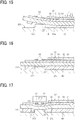
- the height of the protrusion 23f becomes larger than the thickness of the heat insulation layer 40, the surface on the back side of the heater 22, that is, the heat insulation layer 40 separates from the heater holder 23 as illustrated in FIG. 14 .
- the bending of the heater 22 may break the heat insulation layer 40 made of a brittle material.
- the base layer 30 similarly bends, the bending of the base layer 30 does not cause a problem because the base layer 30 according to the present embodiment is made of ductile material which is hard to be damaged even if bend occurs.
- the heat insulation layer 40 separates from the bottom portion 23a of the recessed portion 230 in the side in which the pressure roller presses the heater 22, that is, the right side of the protrusion 23f in FIG. 14 , and the bending of the heat insulation layer 40 increases.
- the heat insulation layer 40 may be thicker than the target thickness (that is the same thickness as the height of the protrusion 23f).
- the target thickness that is the same thickness as the height of the protrusion 23f.
- the number of protrusions 23f is not limited to one and may be more than one.
- two protrusions 23f may be provided and arranged on portions corresponding to the respective electrode 62.
- each protrusion 23f is disposed corresponding to at least the contact point C in each electrode 62.
- the above-described configuration can reduce a production cost because the above-described configuration can set tip areas of the protrusions 23f that need high dimension accuracy smaller than the configuration in which one protrusion 23f supports the portion corresponding to each electrode 62 as illustrated in FIG. 9 .
- three protrusions 23f arranged to form triangle apexes may be provided to support the back-side surface of the base layer 30. This case can further reduce the production cost because the tip area of each protrusion 23f can be further reduced (for example, because each protrusion 23f can be made spherical, to provide point contact with the base layer 30).
- the holes 40a in the heat insulation layer 40 may be separately formed in portions corresponding to the respective electrodes 62. As described above, individually forming the holes 40a in the portions corresponding to the respective electrode 62 enables the portion in which the heat insulation layer 40 is omitted to be minimized, which suppresses the decrease in rigidity that is caused by omitting the heat insulation layer 40.
- the heater holder 23 illustrated in FIG. 18 is preferably applied as the heater holder 23. As illustrated in FIG.
- a plurality of protrusions 23f disposed on the heater holder 23 is inserted into a plurality of holes 40a formed in the heat insulation layer 40, and each of the protrusions 23f supports the back-side surface of the base layer 30.
- the heat insulation layer 40 may be disposed on a portion corresponding to the heat generator 61 and a vicinity of the heat generator 61. This case enables to reduce a size of the heat insulation layer 40 and the production cost.
- the heat insulation layer 40 that is one of the layers in the heater 22 is omitted (not provided) in the portion corresponding to the electrodes 62, but in a second embodiment of the present disclosure, a part of the layers in the heater 22 is partially made thin.
- the portion corresponding to the electrode 62 is thinner than the portion corresponding to the heat generator 61.
- the base layer 30 is disposed in the opposite side with respect to the surface on which the electrode is disposed and forms a single portion having a part corresponding to the electrode 62 and a part corresponding to the heat generator 61, and the part corresponding to the electrode 62 is thinner than the part corresponding to the heat generator 61. Reducing the thickness of the base layer 30 in the portion corresponding to the electrode 62 as described above decreases the variation in the thickness of the base layer 30 at the portion.
- the combined tolerances in the thicknesses of layers of the heater decreases in the portion corresponding to the electrode 62, and the variation in the thickness of the heater 22 also decreases. Since this enables to reduce the variation in the contact pressure from the contact terminals 72 to the electrode 62 and easily manage the contact pressure and prevent the contact pressure from being insufficient or excessive, the contact pressure can be set to the appropriate value (that is, within the appropriate range).
- the protrusion 23f of the heater holder 23 is the contact portion that contacts the base layer 30, but there is the slight gap between the bottom portion 23a of the heater holder 23 and the base layer 30, and the bottom portion 23a is the portion not in contact with the back surface of the heater 22.
- the portion in which the contact portion of the heater holder 23, that is, the protrusion 23f contacts the back surface of the heater 22 is thinner than the portion in which the contact portion that is the protrusion 23f does not contact the back surface of the heater 22.
- the protrusion 23f that supports the thinly formed portion of the base layer 30 from the back side is disposed in the recessed portion 230 of the heater holder 23.
- the current-carrying connector used in the present embodiment has the same configuration as that of the above-described embodiment (the first embodiment) (see FIG. 5 ). That is, the connector includes the contact terminal 72 that sandwiches the heater 22 and the heater holder 23 together from the front side and the back side and holds the heater 22 and the heater holder 23. When the contact terminal 72 holds the heater 22 and the heater holder 23, the pair of contact portions 72a of the contact terminal 72 is pressed against the electrodes 62 of the heater 22. In the above-described configuration in which the contact terminal 72 sandwiches and holds not only the heater 22 but also the heater holder 23, the contact pressure of the contact terminal 72 to the electrode 62 is affected by not only the variation in the thickness of the heater 22 but also the variation in the thickness of the heater holder 23.
- the thickness of the base layer 30 decreases at the portion corresponding to the electrode 62, while the thickness of the heater holder 23 which is provided with the protrusion 23f increases.
- the heater holder 23 is a resin molded article molded by a mold, an error in thickness hardly occurs. Therefore, the variation in the thickness of the heater holder 23 caused by the increase in thickness due to the provision of the protrusion 23f hardly affects the contact pressure of the contact terminal 72 and does not cause a problem.
- a range of the thinly formed base layer 30 is preferably in a range including at least a position corresponding to the contact point C (see FIG. 13 ) between the contact terminal 72 and the electrode 62. Therefore, the base layer 30 may be recessed and thinned only at the portion corresponding to the contact point C and the vicinity thereof. Additionally, similar to the range of the thinly formed base layer 30, the protrusion 23f of the heater holder 23 to support the range is preferably disposed at a position corresponding to at least the contact point C between the contact terminal 72 and the electrode 62.
- the number of the protrusions 23f of the heater holder 23 to support the thinly formed portion of the base layer 30 and a number of the thinly formed portion of the heater holder 23 may be more than one, corresponding to the number of the electrodes 62.
- the protrusion 23f may be arranged to form a vertex of a triangle.
- the back-side portion of the base layer 30 (the lower portion in FIG. 23 , or the portion opposite the portion on which the electrode 62 is disposed) is changed in the thickness direction to make the base layer 30 partially formed.
- the front side portion of the base layer 30 (the upper portion in FIG. 24 ) may be changed in the thickness direction to make the base layer 30 partially thinner.
- a step is formed in the conductor layer 60 on the front side, and the shape is complicated. Therefore, it is difficult to form the conductor layer 60 by the method of forming the conductor layer 60 by screen printing. Therefore, from the viewpoint of ease of formation of the conductor layer 60, as illustrated in FIG. 23 , it is preferable to change the back-side portion of the base layer 30 in the thickness direction.
- FIGS. 25 and 26 are cross-sectional views illustrating variations of the second embodiment.
- the shape of the step in which the thickness of the base layer 30 changes is different compared to the example illustrated in FIG. 23 described above.
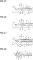
- the step of the base layer 30 is a stepped portion 66 that is formed in a stepwise shape having a plurality of steps in the thickness direction which becomes thinner in a step-by-step manner from the portion corresponding to the heat generator 61 to the portion corresponding to the electrode 62.
- Forming the step of the base layer 30 in the stepwise shape including a plurality of steps enables to make the step (a height) for one step smaller than the step of the base layer 30 that is one step as illustrated in FIG. 23 described above. Therefore, adopting such a configuration enables to form the step (the stepped portion 66) by a method of applying a material paste containing metal powder etc. in a step-like manner while applying masking on the material paste. This method enables to make the base layer 30 in lower cost than a method that forms the large step in the example illustrated in FIG. 23 by cutting.
- the step of the base layer 30 is an inclined portion 67 in which the back-side portion of the base layer inclines in the thickness direction to be the base layer 30 gradually thinner from the portion corresponding to the heat generator 61 to the portion corresponding to the electrode 62.
- the inclined portion 67 is a flat surface, but may be a curved surface.
- the step formed by inclining the base layer 30 can avoid stress concentration such as thermal stress in the step and improve the durability of the base layer 30.
- the thickness of the base layer 30 that is one of the layers in the heater 22 in the portion corresponding to the electrode 62 reduces the variation in the thickness of the heater 22, which results in decrease of variation in contact pressure of the contact terminal.
- the example illustrated in FIGS. 23 to 26 omits the heat insulation layer 40 and the first insulation layer 51 in the first embodiment described above, the examples illustrated in FIGS. 23 to 26 may include the heat insulation layer 40 and the first insulation layer and are not limited by the number of layers in the heater 22 and the type (material) of the layers. Therefore, the layer formed thin in the portion corresponding to the electrode 62 may be one of the layers in the heater 22 which is arbitrarily selected other than the base layer 30.
- the thicknesses of a plurality of layers arbitrarily selected from the layers in the heater 22 and including the base layer 30 may be reduced.
- partially reducing the thickness of at least one of the layers in the heater 22 results in a total thickness T4 in the lamination direction from the front side surface of the conductor layer 60 at the region corresponding to the electrode 62 to the back side surface of the heater 22 that is the back side surface of the base layer 30 in the example illustrated in FIG. 23 thinner than a total thickness T3 in the lamination direction from the front side surface of the conductor layer 60 at the region corresponding to the heat generator 61 to the back side surface of the heater 22 that is the back side surface of the base layer 30 in the example illustrated in FIG. 23 .
- the total thickness in the lamination direction of the portion including the layers in the heater 22 and are layered from the conductor layer 60 toward the base layer 30 is thinner at the region corresponding the electrode 62 (T3) than at the region corresponding to the heat generator 61 (T4).
- FIG. 27 is a cross-sectional view illustrating the heater 22 and the heater holder 23 according to a third embodiment of the present disclosure.
- the heater 22 includes a high thermal conduction layer 50 between the base layer 30 and the heat insulation layer 40.
- the high thermal conduction layer 50 is made of a material having a thermal conductivity higher than that of the base layer 30 and the heat insulation layer 40 and has a length substantially equal to the entire heater 22 in the longitudinal direction of the heater 22.
- the fixing device has an issue that temperature on the end side of a heat generation area that is the temperature outside an area for passing the sheet is excessively high when the sheet having a width smaller than the heat generation area of the heater 22 is continuously passed.
- the high thermal conduction layer 50 as described above is provided and distributes the heat on the end side that may cause the excessive rise in temperature in the longitudinal direction of the heater 22 that is a sheet width direction.
- the high thermal conduction layer 50 can prevent the heater 22 from rising the temperature on the end side even when small-size sheets continuously pass.
- print productivity of the small-size sheets can be improved because there are no needs to set the sheet passing wait time or to slow the sheet passing speed in order to avoid the temperature rise on the end side.
- the high thermal conduction layer 50 is omitted at a portion corresponding to the electrode 62 (that is, provided except for the portion corresponding to the electrode 62) to prevent the contact pressure defect (insufficient contact pressure or excessive contact pressure) of the connector 70 with respect to the heater 22.
- the heat insulation layer 40 is also omitted at the portion corresponding to the electrode 62.
- the heat insulation layer 40 and the high thermal conduction layer 50 are disposed in the opposite side with respect to the surface on which the electrode is disposed, and the heat insulation layer 40 and the high thermal conduction layer 50 have holes corresponding to the electrode 62. Each hole forms a plurality of portions in each of the heat insulation layer 40 and the high thermal conduction layer 50, and the gap formed by the hole exists between the plurality of portions.
- partially omitting the heat insulation layer 40 and the high thermal conduction layer 50 at the portion corresponding to the electrode 62 reduces the combined tolerances of the layers in the heater 22 and the variation in the contact pressure of the contact terminal 72 with respect to the electrode 62.
- the high thermal conduction layer 50 and the heat insulation layer 40 are removed at least the portion corresponding to the contact point C between the contact terminal 72 and the electrode 62 (see FIG. 13 ) in the portion corresponding to the electrode 62 and arranged.
- the current-carrying connector used in the present embodiment has the same configuration as that of the above-described embodiment (the first embodiment) (see FIG. 5 ).
- the high thermal conduction layer 50 and the heat insulation layer 40 have holes 50a and 40a in portions corresponding to the electrode 62. Through the holes 50a and 40a, the protrusion 23f disposed on the heater holder 23 supports the back-side surface of the base layer 30.
- the configuration of the heater holder 23 according to the present embodiment may be the above-described configuration having two protrusions 23f as illustrated in FIG. 18 or the above-described configuration having three protrusions 23f as illustrated in FIG. 19 .
- the hole 50a of the high thermal conduction layer 50 may be separately disposed on the portion corresponding to the electrodes 62. In this case, minimizing the portion on which the high thermal conduction layer 50 is omitted enables providing the high thermal conduction layer 50 on a wide area. Or, conversely, the portion on which the high thermal conduction layer 50 is provided may be a requisite minimum. Since the high thermal conduction layer 50 may be provided at least in the area on which the temperature rise on the end side may occur, for example, similar to the above-described heat insulation layer 40 illustrated in FIG. 22 described above, the high thermal conduction layer 50 may be disposed on a region corresponding to the heat generator 61 and a vicinity of the heat generator 61.
- minimizing the portion on which the high thermal conduction layer 50 is provided reduces cost.
- minimizing the portion on which the high thermal conduction layer 50 is provided can prevent the heat from transmitting to the electrode 62 via the high thermal conduction layer 50, an inexpensive material with low heat resistance may be used as the material of the electrode 62.
- FIG. 28 is a cross-sectional view illustrating a heating body 25 and the connector 70 according to a fourth embodiment of the present disclosure
- the connector 70 directly contacts with the back side of the heating body 25.
- the heater holder 23 is a contact member that directly contacts the back side of the heating body 25.
- the connector 70 is the contact member that directly contacts the back side of the heating body 25.
- the housing 71 of the connector 70 is extended in the longitudinal direction of the heating body 25 that is a right direction in FIG. 28 and bent in the thickness direction of the heating body 25 that is an upper direction in FIG. 28 , and a tip 71a of a bent portion in which the housing 71 of the connector 70 is bent contacts the back side of the base layer 30.
- the tip 71a of the bent portion of the housing 71 is the contact portion that contacts the back side of the heating body 25.
- the heat insulation layer 40 is removed a portion corresponding to a portion on which the tip 71a contacts the back side of the heating body 25, and the hole 40a is provided.
- the heat insulation layer 40 is disposed in the opposite side with respect to the surface on which the electrode is disposed and has a hole corresponding to the contact portion.
- the hole forms a plurality of portions in the heat insulation layer 40, and the gap formed by the holes exists between the plurality of portions.
- a configuration of the present embodiment is different from the configuration of the above-described embodiment and has the hole 40a that is the portion removed the heat insulation layer 40, the hole 40a shifted from the position corresponding to the electrode 62 in the longitudinal direction of the heater 22 or the heating body 25.
- this configuration can also reduce the variation in the contact pressure of the contact terminal 72.
- the configuration including the portion removed the heat insulation layer 40 and shifted from the position corresponding to the electrode 62 is considered that the degree of freedom in design is enhanced because this configuration can reduce the variation in the contact pressure even when providing a part that contacts the heating body on the portion corresponding to the electrode 62 is difficult, for example, when another component is disposed on the portion corresponding to the electrode 62.
- the configuration illustrated in FIG. 23 may be applied to the configuration illustrated in FIG. 28 , that is, the thickness of layer on the portion on which the tip 71a that is the contact portion of the connector 70 contacts the back side of the heating body 25 may be thinner than the thickness of layer on the other portion.
- the above-described embodiments are illustrative and do not limit this disclosure. It is therefore to be understood that within the scope of the appended claims, numerous additional modifications and variations are possible to this disclosure otherwise than as specifically described herein. Therefore, the above-described embodiments and their variations may be combined as appropriate.
- the above-described embodiment is configured by either removing a part of at least one of the layers in the heater or reducing a thickness of the part of at least one of the layers in the heater, but the heater may be configured by removing a part of at least one of the layers in the heater and reducing a thickness of the part of another one of the layers in the heater.
- the plurality of layers in the heater 22 may be the base layer and layers having different thermal conductivity from the base layer.
- the first insulation layer may be provided on the opposite side of the layer having different thermal conductivity from the base layer, or the second insulation layer may be provided on the surface on which the electrode and the heat generator connected to the electrode are disposed.
- the layer having different thermal conductivity from the base layer may have higher thermal conductivity than the base layer or lower thermal conductivity than the base layer.
- the layer removed the part of itself as described above is not limited to the low thermal conduction layer having lower thermal conductivity than the base layer 30, such as the heat insulation layer 40 described above.
- a heat-equalization layer thermalally conductive metal layer
- the layer removed a part of itself may be the layer having higher thermal conductivity than the base layer 30 (that is, the heat-equalization layer or the thermally conductive metal layer), or the layer having lower thermal conductivity than the base layer 30 (that is, the heat insulation layer or the low thermal conduction layer). That is, the layer removed a part of itself may be the layer having different thermal conductivity from the base layer 30.
- the first insulation layer 51 and the second insulation layer 52 may be removed, and the heater 22 may be configured by the heat insulation layer 40, the base layer 30, and the conductor layer 60.
- the heater 22 may have a configuration including a lowest layer 41 on the back side of the heat insulation layer 40 in addition to the heat insulation layer 40, the base layer 30, the first insulation layer 51, the conductor layer 60, and the second insulation layer 52.
- the heat insulation layer 40 is removed the portion corresponding to the electrode 62.
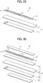
- the plate 101 provided with the electrode 62 and the heat generator 61 may be configured by the heat insulation layer 40, the base layer 30, and the first insulation layer 51 as illustrated in FIG. 4 , or by the heat insulation layer 40 and the base layer 30 as illustrated in FIG. 29 .
- the plate 101 may be configured by the lowest layer 41, the heat insulation layer 40, the base layer 30, and the first insulation layer 51 as illustrated in FIG. 30 .
- the layer removed the part of itself or thinly formed the part of itself, which is at least one layer of the plurality of layers included in the plate 101 described above, may be an outermost layer to the surface on which the electrode 62 is disposed (see FIGS.
- the layer removed the part of itself may be the lowest layer 41 or the base layer 30 in addition to the heat insulation layer 40.
- the heater 22 has the two heat generators 61 are disposed parallel to each other in the longitudinal direction of the base layer 30 and electrically connected in series, but, as in the example illustrated in FIG. 31 , the heater 22 may have a plurality of heat generators 61 arranged at intervals in the longitudinal direction of the base layer 30 (that is also a belt width direction).
- each heat generator 61 may be formed in a shape having a plurality of folded portions and electrically connected in parallel to a pair of electrodes 62 disposed at both ends in the longitudinal direction of the base layer 30.
- the gap between the heat generators 61 adjacent to each other is preferably 0.2 mm or more, more preferably 0.4 mm or more from the viewpoint of maintaining the insulation between the heat generators 61.
- the gap between the heat generators 61 adjacent to each other is preferably 5 mm or less, more preferably 1 mm or less from the viewpoint of reducing temperature unevenness along the longitudinal direction because too large gap between the heat generators 61 adjacent to each other easily causes a temperature drop in the gap.
- electrode 62 of heater 22 is connected to the heat generator 61
- the present disclosure is not limited to this.
- the present disclosure is also applicable to a configuration in which the electrode is connected to a temperature sensor such as a thermistor.
- the present disclosure is also applicable, for example, to fixing devices as illustrated in FIGS. 32 to 34 , in addition to the fixing device illustrated in FIG. 2 .
- the configuration of each fixing devices illustrated in FIGS. 32 to 34 is briefly described below.
- the fixing device 9 illustrated in FIG. 32 includes a pressurization roller 90 opposite the pressure roller 21 with respect to the fixing belt 20 and heats the fixing belt 20 sandwiched by the pressurization roller 90 and the heater 22.
- a nip formation pad 91 is disposed inside the inner circumferential surface of the fixing belt 20.
- the stay 24 supports the nip formation pad 91, and the nip formation pad 91 and the pressure roller 21 sandwiches the fixing belt 20 to form the nip N.
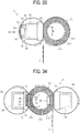
- the fixing device 9 illustrated in FIG. 33 is omitted the above described pressurization roller 90 and includes the heater 22 configured by an arc-shaped plate having a curvature of the fixing belt 20 to keep a circumferential contact length between the fixing belt 20 and the heater 22.
- the fixing device 9 illustrated in FIG. 33 is identical to the fixing device 9 illustrated in FIG. 32 in terms of the others.
- the fixing device 9 illustrated in FIG. 34 includes a pressing belt 92 in addition to the fixing belt 20 and has a heating nip (a first nip) N1 and the fixing nip (a second nip) N2 separately. That is, the nip formation pad 91 and the stay 93 are disposed opposite the fixing belt 20 with respect to the pressure roller 21, and the pressing belt 92 is rotatably arranged to wrap around the nip formation pad 91 and the stay 93.
- the sheet P passes through the fixing nip N2 between the pressing belt 92 and the pressure roller 21 and is applied to heat and pressure, and the image is fixed on the sheet P.
- the fixing device 9 illustrated in FIG. 34 is identical to the fixing device 9 illustrated in FIG. 2 in terms of the others.
- the portion corresponding to at least one part of the electrode (that is, the contact point C) in the layer is removed or made thinner. Or, the portion in the one layer is removed, and the portion in the other layer is made thinner. These can reduce the variation in thickness of the heater and prevent contact pressure failure of the connector with respect to the heater.
- adopting the configuration of the present disclosure enables to ensure the electrical connection between the connector and the heater, simplify the configuration of the connector, and prevent the heating device from increasing the cost and the size.
- the present disclosure can stabilizes the contact pressure of the connector with respect to the heater. That is, without adopting a connector which elastically contacts the heater from both sides in the thickness direction, the present disclosure can simplify the configuration and reduce the cost because the contact pressure defects of the connector with respect to the heater can be effectively prevented.
- the heater and the heating device according to the present disclosure is also applicable to a dryer to dry ink applied to the sheet and a coating device (a laminator) that heats, under pressure, a film as a covering member onto the surface of the sheet such as paper.
- the image forming apparatus 100 may be a copier, a facsimile machine, a multifunction peripheral (MFP) having at least two of copying, printing, scanning, facsimile, and plotter functions in addition to the printer.
- Embodiments of the present disclosure may be applied to an ink jet type image forming apparatus in addition to the electrophotographic type image forming apparatus.
Landscapes
- Physics & Mathematics (AREA)
- General Physics & Mathematics (AREA)
- Fixing For Electrophotography (AREA)
- Control Of Resistance Heating (AREA)
- Resistance Heating (AREA)
Abstract
Description
- Embodiments of the present disclosure generally relate to a heater, a heating device, a fixing device and an image forming apparatus.
- A laminated heater having a planar resistive heat generator is known as a heater used for a drying device to dry ink on a sheet or a fixing device to fix toner on the sheet by heat in an image forming apparatus such as a printer and a copier.
- The laminated heater generates heat when power is supplied to the resistive heat generator. Therefore, the laminated heater includes an electrode to which a connector is electrically connected to supply power from the power supply.
- For example,
JP-2014-109754-A - The laminated heater has an issue that variation in contact pressure of the contact terminal pressed against the electrode causes an application of the contact pressure stronger than necessary contact pressure to the electrode, or conversely, shortage of the contact pressure.
- As a solution to such the issue,
JP-2014-109754-A - It is a general object of the present disclosure to provide an improved and useful heater in which the above-mentioned problems are eliminated. In order to achieve the above-mentioned object, there is provided a heater according to
claim 1. Advantageous embodiments are defined by the dependent claims. Advantageously, the heater includes an electrode, a heat generator, and a plate having a portion corresponding to the electrode thinner than a portion corresponding to the heat generator. - The present disclosure enables to reduce the variation in the contact pressure of the contact terminal with respect to the electrode and set the contact pressure to an appropriate value, that is, within an appropriate range.
- The aforementioned and other aspects, features, and advantages of the present disclosure would be better understood by reference to the following detailed description when considered in connection with the accompanying drawings, wherein:
-
FIG. 1 is a schematic diagram of an image forming apparatus according to an embodiment of the present disclosure; -
FIG. 2 is a schematic diagram of a fixing device; -
FIG. 3 is a plan view of a heater; -
FIG. 4 is an exploded perspective view of the heater; -
FIG. 5 is a perspective view of a connector; -
FIG. 6 is a perspective view illustrating the connector connected to the heater; -
FIG. 7 is a perspective view illustrating the heater and a heater holder according to a first embodiment of the present disclosure; -
FIG. 8 is a bottom view illustrating the heater viewed from a back side; -
FIG. 9 is a longitudinal cross-sectional view illustrating the heater held by the heater holder; -
FIG. 10 is a cross-sectional view of the heater held by the heater holder along a line A-A ofFIG. 9 ; -
FIG. 11 is a cross-sectional view illustrating the heater held by the heater holder and connected to a connector; -
FIG. 12 is a cross-sectional view illustrating a comparative example of the heater including a heat insulation layer disposed on a portion corresponding to an electrode; -
FIG. 13 is a plan view illustrating an arrangement of a protrusion with respect to contact points between contact terminals and electrodes; -
FIG. 14 is a cross-sectional view illustrating an example in which there is no gap between the protrusion and a heat insulation layer; -
FIG. 15 is a cross-sectional view illustrating an example in which the predetermined gap is provided between the protrusion and the heat insulation layer; -
FIG. 16 is a cross-sectional view illustrating an example in which there is no gap between the protrusion and the heat insulation layer; -
FIG. 17 is a cross-sectional view illustrating an example in which the predetermined gap is provided between the protrusion and the heat insulation layer; -
FIG. 18 is a cross-sectional view illustrating an example in which the protrusion is provided at a portion corresponding to the electrodes; -
FIG. 19 is a perspective view illustrating an example in which multiple protrusions are disposed at vertexes of a triangle; -
FIG. 20 is a perspective view illustrating an example of the heater having holes formed at portions corresponding to the electrodes; -
FIG. 21 is a cross-sectional view illustrating an example of the heater illustrated inFIG. 20 held by the heater holder illustrated inFIG. 18 ; -
FIG. 22 is a perspective view illustrating an example of the heater including the heat insulation layer disposed corresponding to a heat generator and a vicinity of the heat generator; -
FIG. 23 is a cross-sectional view illustrating the heater according to a second embodiment of the present disclosure; -
FIG. 24 is a cross-sectional view illustrating an example of the heater in which a front surface of a base layer is changed so that an end portion is thinner than a center portion in a thickness direction; -
FIG. 25 is a cross-sectional view illustrating an example of the heater including the base layer having a stepped portion including a plurality of steps; -
FIG. 26 is a cross-sectional view illustrating an example of the heater including the base layer having a sloping stepped portion; -
FIG. 27 is a cross-sectional view illustrating the heater and the heater holder according to a third embodiment of the present disclosure; -
FIG. 28 is a cross-sectional view illustrating a heating body and the connector according to a fourth embodiment of the present disclosure; -
FIG. 29 is an exploded perspective view illustrating an example of another heater; -
FIG. 30 is an exploded perspective view illustrating an example of still another heater; -
FIG. 31 is an exploded perspective view illustrating an example of yet a further different heater; -
FIG. 32 is a schematic diagram illustrating a configuration of another fixing device; -
FIG. 33 is a schematic diagram illustrating a configuration of still another fixing device; and -
FIG. 34 is a schematic diagram illustrating a configuration of yet a further different fixing device. - The accompanying drawings are intended to depict embodiments of the present disclosure and should not be interpreted to limit the scope thereof. The accompanying drawings are not to be considered as drawn to scale unless explicitly noted.
- In describing embodiments illustrated in the drawings, specific terminology is employed for the sake of clarity. However, the disclosure of this specification is not intended to be limited to the specific terminology so selected and it is to be understood that each specific element includes all technical equivalents that have a similar function, operate in a similar manner, and achieve a similar result.
- Although the embodiments are described with technical limitations with reference to the attached drawings, such description is not intended to limit the scope of the disclosure and all of the components or elements described in the embodiments of this disclosure are not necessarily indispensable.
- Referring now to the drawings, embodiments of the present disclosure are described below. In the drawings illustrating the following embodiments, the same reference numbers are allocated to elements having the same function or shape and redundant descriptions thereof are omitted below.
-
FIG. 1 is a schematic diagram illustrating a configuration of an image forming apparatus according to an embodiment of the present disclosure. - The
image forming apparatus 100 illustrated inFIG. 1 includes fourimage forming units image forming units image forming units photoconductor 2 in a drum-like shape as an image bearer; acharger 3 to charge a surface of thephotoconductor 2; a developingdevice 4 configured to form a toner image by supplying toner, as a developer, to a surface of thephotoconductor 2; and a cleaner 5 to clean the surface of thephotoconductor 2. - The
image forming apparatus 100 further includes an exposure device 6 to expose the surface of eachphotoconductor 2 to form an electrostatic latent image, asheet feeder 7 to supply a sheet P as a recording medium, atransfer device 8 to transfer the toner image formed on the eachphotoconductor 2 onto the sheet P, afixing device 9 to fix the transferred toner image onto the sheet P, and anoutput device 10 to eject the sheet P outside theimage forming apparatus 100. - The
transfer device 8 includes: anintermediate transfer belt 11 in the form of an endless belt stretched taut with multiple rollers, as an intermediate transferor; fourprimary transfer rollers 12 each as a primary transferor to transfer the toner image formed on eachphotoconductor 2 onto theintermediate transfer belt 11; and asecondary transfer roller 13 as a secondary transferor to transfer the toner image transferred onto theintermediate transfer belt 11 onto the sheet P. Theprimary transfer rollers 12 are in contact with therespective photoconductors 2 via theintermediate transfer belt 11. Therefore, theintermediate transfer belt 11 is in contact with therespective photoconductors 2, thus forming primary transfer nips therebetween. Thesecondary transfer roller 13 contacts, via theintermediate transfer belt 11, one of the plurality of rollers around which theintermediate transfer belt 11 is stretched. Thus, the secondary transfer nip is formed between thesecondary transfer roller 13 and theintermediate transfer belt 11. - In the
image forming apparatus 100, asheet conveyance path 14 is formed through which the sheet P fed from thesheet feeder 7 is conveyed. Atiming roller pair 15 is disposed on thesheet conveyance path 14 on the way from thesheet feeder 7 to the secondary transfer nip (the secondary transfer roller 13). - Next, a description is given of a print operation of the
image forming apparatus 100 with reference toFIG. 1 . - As a print operation start is instructed, in each of the
image forming units photoconductors 2 are each driven to rotate clockwise inFIG. 1 and the surfaces thereof are uniformly charged to a high potential by therespective chargers 3. Subsequently, according to either image data of a document scanned by a scanner or print data instructed from a terminal, the exposure device 6 exposes the surface of thephotoconductor 2. Thus, the potential of the exposed portion decreases, and an electrostatic latent image is formed. The developingdevice 4 supplies toner to the electrostatic latent image, thereby developing the latent image into the toner image on each of thephotoconductors 2. - The toner image on each of the
photoconductors 2 reaches the primary transfer nip at each of theprimary transfer rollers 12 in accordance with rotation of each of thephotoconductors 2 and is sequentially transferred and superimposed onto theintermediate transfer belt 11 that is driven to rotate counterclockwise inFIG. 1 . In accordance with rotation of theintermediate transfer belt 11, the toner image transferred onto theintermediate transfer belt 11 reaches the secondary transfer nip at thesecondary transfer roller 13 and is transferred onto the conveyed sheet P at the secondary transfer nip. The sheet P is fed from thesheet feeder 7. Thetiming roller pair 15 temporarily stops the sheet P fed from thesheet feeder 7 and conveys the sheet P to the secondary transfer nip, timed to coincide with the toner image on theintermediate transfer belt 11. Thus, a full-color toner image is formed on the sheet P. After the toner image is transferred from each of thephotoconductors 2 onto theintermediate transfer belt 11, each of cleaners 5 removes residual toner on each of thephotoconductors 2. - The sheet P transferred the toner image is conveyed to the
fixing device 9 that fixes the toner image on the sheet P. Subsequently, theoutput device 10 ejects the sheet P outside theimage forming apparatus 100, and a series of print operations are completed. - Next, a configuration of the fixing
device 9 is described. - As illustrated in
FIG. 2 , the fixingdevice 9 according to the present embodiment includes anendless fixing belt 20 as a fixing rotator, apressure roller 21 as an opposed rotator to contact an outer circumferential surface of the fixingbelt 20 and form a nip N, and aheating device 19 to heat the fixingbelt 20. Theheating device 19 includes alaminated heater 22 as a heater, aheater holder 23 as a holder to hold theheater 22, and astay 24 as a supporter to support theheater holder 23. - The fixing
belt 20 includes, for example, a tubular base made of polyimide (PI), the tubular base having an outer diameter of 25 mm and a thickness of from 40 to 120 µm. On the outermost layer of the fixingbelt 20, a release layer made of a fluorine-based resin, such as a perfluoroalkoxy alkane (PFA) or polytetrafluoroethylene (PTFE), having a thickness of from 5 to 50 µm, is formed in order to improve durability and ensure releasability. An elastic layer made of rubber having a thickness of from 50 to 500 µm may be provided between the base and the release layer. The base of the fixingbelt 20 is not limited to polyimide, and thus may be made of heat-resistant resin, such as polyetheretherketone (PEEK), or a metal, such as nickel (Ni) or stainless steel (SUS). The inner circumferential surface of the fixingbelt 20 may be coated with polyimide or polytetrafluoroethylene (PTFE) as a slide layer. - The
pressure roller 21 having, for example, an outer diameter of 25 mm, includes abar 21a made of solid iron, anelastic layer 21b on the surface of thebar 21a, and arelease layer 21c formed on the outside of theelastic layer 21b. Theelastic layer 21b is made of silicone rubber and has, for example, a thickness of 3.5 mm. Preferably, therelease layer 21c is formed by a fluororesin layer having, for example, a thickness of approximately 40 µm on the surface of theelastic layer 21b to improve releasability. - The
heater 22 extends in a longitudinal direction thereof parallel to a width direction of the fixingbelt 20. Theheater 22 includes aheat insulation layer 40, abase layer 30, afirst insulation layer 51, aconductor layer 60 that includes aheat generator 61, and asecond insulation layer 52, all of which are layered, in the order just given, onto and from theheater holder 23 toward the fixingbelt 20, that is, the nip N. - The
heater holder 23 and thestay 24 are disposed inside the inner circumferential surface of the fixingbelt 20. Thestay 24 is configured by a channeled metallic member, and both side plates of the fixingdevice 9 support respective end portions of thestay 24. Supporting theheater holder 23 and theheater 22 held by theheater holder 23 by thestay 24 causes theheater 22 to be subjected to a pressing force of thepressure roller 21 while thepressure roller 21 presses the fixingbelt 20 and forms the nip N stably. - The
heater holder 23 is preferably made of heat-resistant material because heat from theheater 22 causes theheater holder 23 get hot. Theheater holder 23 made of heat-resistant resin having low thermal conduction, such as a liquid crystal polymer (LCP), reduces heat transfer from theheater 22 to theheater holder 23 and provides efficient heating of the fixingbelt 20. - A biasing member such as a spring presses the
pressure roller 21 against the fixingbelt 20. As a result, thepressure roller 21 is pressed against theheater 22 via the fixingbelt 20 to form the nip N between the fixingbelt 20 and thepressure roller 21. A driver drives and rotates thepressure roller 21 in a direction of an arrow illustrated inFIG. 2 , and this rotation of thepressure roller 21 rotates the fixingbelt 20. - When the print operation starts, the
pressure roller 21 is driven to rotate, and the fixingbelt 20 starts to be rotated. Theheater 22 is supplied with power, heating the fixingbelt 20. When the temperature of the fixingbelt 20 reaches a predetermined target temperature called a fixing temperature, as illustrated inFIG. 2 , the sheet P bearing an unfixed toner image is conveyed to the nip N between the fixingbelt 20 and thepressure roller 21, and the unfixed toner image is heated and pressed on to the sheet P and fixed thereon. -
FIG. 3 is a plan view of theheater 22 as viewed from the front side, andFIG. 4 is an exploded perspective view of theheater 22. In the following description according to the present embodiment, the fixingbelt 20 side, that is, the nip N side with respect to theheater 22 is referred to as "front side", and theheater holder 23 side is referred to as "back side". - As illustrated in
FIG. 4 , theheater 22 according to the present embodiment is the heater including a plurality of layers, electrodes, and the heat generator connected to the electrodes. The plurality of layers included in theheater 22 are integrally formed. A method to form the layers integrally is, for example, a method coating thebase layer 30. In the present embodiment, examples of the plurality of layers included in theheater 22 are as follows. Theheater 22 according to the present embodiment includes theplanar base layer 30, thefirst insulation layer 51 disposed on the front side of thebase layer 30, theconductor layer 60 disposed on the front side of thefirst insulation layer 51, thesecond insulation layer 52 that covers the front side of theconductor layer 60, and theheat insulation layer 40 disposed on the back side of thebase layer 30 and is configured by stacking the plurality of these layers. Theconductor layer 60 includes a pair ofheat generators 61 formed of the laminated heaters, a pair ofelectrodes 62 disposed on one end in the longitudinal direction of eachheat generator 61, and a plurality ofpower supply lines 63 connecting theelectrodes 62 and theheat generators 61 to each other. In addition, as illustrated inFIG. 3 , at least one part of eachelectrode 62 in theconductor layer 60 is exposed without being covered by thesecond insulation layer 52 to ensure connection with a connector described later. - The
heat generator 61 may be made, for example, by coating on thebase layer 30 with paste in which silver palladium (AgPd) and glass powder are compounded, by screen printing, after that, by baking thebase layer 30. The material of theheat generator 61 may include a resistance material, such as silver alloy (AgPt) or ruthenium oxide (RuO2), other than the above material. In the present embodiment, the pair ofheat generators 61 extend in the longitudinal direction of thebase layer 30 in parallel with each other. Right ends of theheat generators 61 inFIG. 3 , that is, ends ofheat generators 61 in one side are electrically connected to each other through thepower supply line 63, and left ends of theheat generators 61 inFIG. 3 , that is, ends ofheat generators 61 in the other side are electrically connected to theelectrodes 62 through the differentpower supply line 63. Thepower supply lines 63 are made of a conductor having a resistance value smaller than that of theheat generators 61. Silver (Ag), silver palladium (AgPd) or the like may be used as a material of thepower supply line 63 or theelectrode 62, and screen-printing such a material forms thepower supply line 63 or theelectrode 62. - Although the
heat generator 61 is disposed on the front side of thebase layer 30 in the present embodiment, alternatively, theheat generator 61 may be disposed on the back side of thebase layer 30. In that case, since the heat of theheat generator 61 is transmitted to the fixingbelt 20 through thebase layer 30, it is preferable that thebase layer 30 be made of a material with high thermal conductivity such as aluminum nitride. Making thebase layer 30 with a material having a high thermal conductivity enables to sufficiently heat the fixingbelt 20 even if theheat generator 61 is disposed on the back side of thebase layer 30. Even when thebase layer 30 is made of aluminum nitride, coating the materials of the layers other than thebase layer 30 enables integrally forming the layers. - The
base layer 30 is made of a metal material such as stainless steel (SUS), iron, or aluminum. Or, thebase layer 30 may be made of ceramic, glass, etc. other than the metal material. Thefirst insulation layer 51, thesecond insulation layer 52, and theheat insulation layer 40 are made of material having electrical insulation, high thermal conductivity, and heat resistance. In particular, materials having high insulating properties and heat resistance are preferable. Specifically, examples of these materials include heat-resistant resins such as glass, ceramic, and polyimide (PI). Increasing a thickness of each of thefirst insulation layer 51 and thesecond insulation layer 52 improves the electrical insulation but decreases thermal conductivity from theheat generator 61 to the fixingbelt 20 and increase the cost. Therefore, the thickness of thefirst insulation layer 51 and thesecond insulation layer 52 is preferably 10 µm to 300 µm, and more preferably 30 µm to 150 µm. In the present embodiment, in order to increase the thermal conductivity, each of thefirst insulation layer 51 and thesecond insulation layer 52 is made of glass with a thickness of 100 µm to which a ceramic filler is added. Since theheat insulation layer 40 is required to have heat resistance and heat insulation, theheat insulation layer 40 is made of glass, ceramics, or heat resistant resin such as polyimide. Increasing a thickness of theheat insulation layer 40 improves heat insulation but increases the cost. Therefore, the thickness of theheat insulation layer 40 is preferably 10 µm to 300 µm, and more preferably 30 µm to 150 µm. In the present embodiment, in order to improve the heat insulation, theheat insulation layer 40 is made of glass with a thickness of 100 µm. -
FIG. 5 is a perspective view illustrating theconnector 70 coupled to theheater 22. Theheating device 19 according to the present embodiment includes theconnector 70 to supply power to theheat generator 61 of theheater 22. As illustrated inFIG. 5 , theconnector 70 includes ahousing 71 made of resin and acontact terminal 72 including a flat spring fixed to thehousing 71. Thecontact terminal 72 has a pair ofcontact portions 72a to contact therespective electrodes 62 of theheater 22. In addition, apower supply harness 80 is coupled to theconnector 70. - As illustrated in
FIG. 6 , theconnector 70 is attached so as to sandwich theheater 22 and theheater holder 23 from the front side and the back side together. Thus, thecontact portions 72a of thecontact terminal 72 elastically contact and press against theelectrodes 62 of theheater 22, and theheat generator 61 is electrically connected to the power supply provided in the image forming apparatus via theconnector 70 and can receive power from the power supply. - In the configuration in which the
contact terminal 72 is pressed against theelectrode 62 and coupled to theelectrode 62, as described in the present embodiment, any variation in the thickness (that is, a length in a lamination direction) of theheater 22 due to the combined tolerances of layers in theheater 22 changes a contact position between thecontact terminal 72 and theelectrode 62 of theheater 22 in the thickness direction. As a result, the contact pressure at thecontact terminal 72 with respect to theelectrode 62 also varies. Therefore, since an increase of the variation in a thickness of theheater 22 results in an increase in the contact pressure of thecontact terminal 72, the increase of the variation in the thickness of theheater 22 complicates control of the contact pressure to an appropriate value (within an appropriate range). If the contact pressure of thecontact terminal 72 falls below the appropriate range, shortage of the contact pressure hinders maintaining electrical continuity, and an adequate electric power supply to theheater 22 is not ensured. In contrast, if the contact pressure of thecontact terminal 72 exceeds an appropriate range, thecontact terminal 72 and theelectrode 62 of theheater 22 will wear when theheater 22 moves minutely due to vibration at the time of driving and power supply to theheater 22 becomes irregular. The heater moves slightly because the heater expands and contracts in the longitudinal direction of the heater due to heat and vibrates when the fixing belt vibrates due to acceleration and deceleration when the gear does not mesh properly with the pressure roller. In addition, the heater and the heater holder move slightly because sliding friction works the heater and the heater holder when the fixing belt slides on the heater and the heater holder. - A detailed description is given of the configuration of the heating device according to the present embodiment as follows. In the configuration according to the present embodiment, the following measures are taken to prevent above-described contact pressure defects (insufficient contact pressure or excessive contact pressure) of the
contact terminal 72 caused by the variation in the thickness of theheater 22. -
FIG. 7 is a perspective view illustrating theheater 22 and theheater holder 23 according to the present embodiment.FIG. 8 is a bottom view illustrating theheater 22 viewed from a back side. - As illustrated in
FIGS. 7 and 8 , theheater 22 in the present embodiment has arectangular hole 40a formed in theheat insulation layer 40 disposed on the back side of theheater 22, that is, the side opposite to the side on which theconductor layer 60 is disposed. In other words, theheat insulation layer 40 is disposed in the opposite side with respect to a surface on which the electrode is disposed. Thehole 40a is disposed at a position corresponding to theelectrodes 62 disposed on the front side of thebase layer 30. That is, theheat insulation layer 40 is disposed on the back side of the base layer except for the back-side portion of thebase layer 30 corresponding to theelectrodes 62, and a surface on the back-side portion of thebase layer 30 corresponding to theelectrode 62 is exposed. In other words, theheat insulation layer 40 has a plurality of portions around thehole 40a, and has a gap formed by thehole 40a between the plurality of portions. - On the other hand, the
heater holder 23 includes aprotrusion 23f in a recessedportion 230 of theheater holder 23 in which theheater 22 is accommodated. The recessedportion 230 has abottom portion 23a formed in a rectangular shape substantially the same size as theheater 22, and fourside surface portions bottom portion 23a. In the recessedportion 230, theprotrusion 23f is provided in the position corresponding to thehole 40a formed in theheat insulation layer 40 so that theprotrusion 23f protrudes from thebottom portion 23a. -
FIG. 9 is a longitudinal cross-sectional view illustrating theheater 22 held by theheater holder 23, andFIG. 10 is a cross-sectional view of the heater held by the heater holder along a line A-A ofFIG. 9 . - As illustrated in
FIGS. 9 and 10 , when theheater 22 is accommodated and held in the recessedportion 230 of theheater holder 23, theprotrusion 23f of theheater holder 23 is inserted into thehole 40a of theheat insulation layer 40, and a tip of theprotrusion 23f is in contact with the back surface of thebase layer 30. As described above, the tip of theprotrusion 23f contacts the back surface of thebase layer 30, and theprotrusion 23f supports thebase layer 30. Theprotrusion 23f of theheater holder 23 is a contact portion that contacts thebase layer 30, but there is a slight gap between thebottom portion 23a of theheater holder 23 and theheat insulation layer 40, and thebottom portion 23a is a portion not in contact with the back surface of theheater 22. That is, in the present embodiment, theheat insulation layer 40 is removed and thehole 40a is provided in at least one part of the portion on which the contact portion of theheater holder 23, that is, theprotrusion 23f, contacts the back surface of theheater 22. -
FIG. 11 is a cross-sectional view illustrating theheater 22 held by theheater holder 23 and connected to theconnector 70. - As illustrated in
FIG. 11 , when theconnector 70 is attached, theheater 22 and theheater holder 23 are sandwiched from the front side and the back side together and held by thecontact terminal 72. In addition, in this state, the pair ofcontact portions 72a of thecontact terminal 72 is pressed against theelectrodes 62 of theheater 22. - As described above, the variation in the thickness of the
heater 22 at thecontact portions 72a on which thecontact terminal 72 is pressed against theelectrodes 62 varies the contact pressure of thecontact terminal 72 on theelectrode 62. Such variation in the thickness of theheater 22 tends to increase as the number of layers in theheater 22 increases. Conversely, decreasing the number of layers in theheater 22 can reduce the variation in the thickness of theheater 22. - Focusing on such a point, as illustrated in
FIGS. 8 to 11 , theheater 22 in the present embodiment omits theheat insulation layer 40 on the back side of thebase layer 30 corresponding to theelectrodes 62, and the number of layers in theheater 22 is reduced at the contact points between theelectrodes 62 and thecontact terminals 72. This can reduce the variation in the thickness of theheater 22 at the contact points between theelectrodes 62 and thecontact terminals 72 compared with the heater including theheat insulation layer 40 disposed on a portion corresponding to theelectrodes 62 as illustrated inFIG. 12 because the number of layers in theheater 22 on the portion corresponding to theelectrodes 62 is small, and, therefore, the combined tolerances of the layers in the heater decreases. As a result, since the variation in the contact pressure of thecontact terminals 72 is reduced, and since the contact pressure can be easily managed and prevented from being insufficient or excessive, the contact pressure can be set to the appropriate value (that is, within the appropriate range). - As described above, in the present embodiment, since the
heat insulation layer 40 is omitted in a portion corresponding to theelectrode 62, as illustrated inFIG. 9 , a total thickness T2 in the lamination direction from a front side surface of theconductor layer 60 at the portion corresponding to theelectrode 62 to a back side surface of theheater 22 that is the back side surface of thebase layer 30 in the example illustrated inFIG. 9 is thinner than a total thickness T1 in the lamination direction from a front side surface of theconductor layer 60 at a portion corresponding to theheat generator 61 to the back side surface of theheater 22 that is a back side surface of theheat insulation layer 40 in the example illustrated inFIG. 9 by the thickness of theheat insulation layer 40. In other words, the total thickness in the lamination direction of the portion including the layers in theheater 22 and are layered from theconductor layer 60 toward thebase layer 30 is thinner at the portion corresponding the electrode 62 (T1) than at the portion corresponding to the heat generator 61 (T2). Generally, the variation in thickness tends to increase as the thickness of a member increases. Accordingly, as theheat insulation layer 40 becomes thicker, the effect of reducing the variation in heater thickness by partially omitting theheat insulation layer 40 becomes greater. Therefore, the thickness of theheat insulation layer 40 is desirably, for example, 50 µm or more. From the same viewpoint, the thickness of theheat insulation layer 40 is preferably 100 µm or more and more preferably 120 µm or more. In the laminated heater used in the fixing device, since an upper limit of the thickness of theheat insulation layer 40 is generally 175 µm or less, the most preferable range of the thickness of theheat insulation layer 40 is from 120 µm to 175 µm. Further, in the present embodiment, since the thickness of theheat insulation layer 40 corresponds to the difference between the total thickness T1 at the portion corresponding to theheat generator 61 and the total thickness T2 at the portion corresponding to theelectrode 62, in other words, the difference between these layer thicknesses becomes more preferable as the difference becomes 50 µm or more, 100 µm or more, and 120 µm or more, and the most preferable range is 120 µm or more and 175 µm or less. - In the present embodiment, since the
heat insulation layer 40 is not disposed at the portion corresponding to theelectrode 62, theprotrusion 23f is disposed on theheater holder 23 to support thebase layer 30 from the back side at the portion corresponding to theelectrode 62. As described above, since theprotrusion 23f disposed on theheater holder 23 supports the back side of thebase layer 30, the bending of theheater 22 decreases, and the contact pressure of thecontact terminal 72 with respect to theelectrode 62 becomes stable. In addition, decrease of the bending of theheater 22 can prevent damage to theheater 22 due to the bending. - Based on the above described function of the
protrusion 23f, theprotrusion 23f is preferably disposed at a position on which the contact pressure from thecontact terminal 72 to theelectrode 62 can be effectively received. Specifically, as illustrated inFIG. 13 , theprotrusion 23f is preferably disposed at a position corresponding to at least the contact position C between thecontact terminal 72 and theelectrode 62 in a planar view. Disposing theprotrusion 23f at such a position enables theprotrusion 23f to effectively receive the contact pressure from thecontact terminal 72, stabilizes the contact pressure, and improves the certainty of preventing breakage of theheater 22. - A height of the
protrusion 23f (that is, a protrusion amount) is preferably set to be the same as the thickness of theheat insulation layer 40 so that theheater 22 can be reliably supported without bending. However, in practice, it is difficult to completely avoid errors in the thickness of theheater holder 23 and theheat insulation layer 40. If the height of theprotrusion 23f becomes larger than the thickness of theheat insulation layer 40, the surface on the back side of theheater 22, that is, theheat insulation layer 40 separates from theheater holder 23 as illustrated inFIG. 14 . In this case, since application of a pressing force F of the pressure roller to theheater 22 causes a bending of theheater 22, the bending of theheater 22 may break theheat insulation layer 40 made of a brittle material. In addition, although thebase layer 30 similarly bends, the bending of thebase layer 30 does not cause a problem because thebase layer 30 according to the present embodiment is made of ductile material which is hard to be damaged even if bend occurs. - In order to reduce the above-described bending of the
heat insulation layer 40, as illustrated inFIG. 15 , it is preferable to set a gap D between theprotrusion 23f and theheat insulation layer 40 in a direction intersecting the thickness direction and in a side in which the pressure roller presses theheater 22, that is, a right side of theprotrusion 23f inFIG. 15 . Since setting the gap D between theprotrusion 23f and theheat insulation layer 40 described above results in arrangement of theheat insulation layer 40 to a region that does not cause bending, theheat insulation layer 40 does not bend and separate from theheater holder 23, and theheater holder 23 contacts theheat insulation layer 40. This avoids breaking theheat insulation layer 40 due to the bending. On the other hand, in an example illustrated inFIG. 14 , since the above-described gap D is not sufficiently disposed, theheat insulation layer 40 separates from thebottom portion 23a of the recessedportion 230 in the side in which the pressure roller presses theheater 22, that is, the right side of theprotrusion 23f inFIG. 14 , and the bending of theheat insulation layer 40 increases. - Moreover, contrary to the above-described example illustrated in
FIG. 14 , as illustrated inFIG. 16 , theheat insulation layer 40 may be thicker than the target thickness (that is the same thickness as the height of theprotrusion 23f). In this case, when theheater 22 is accommodated in the recessedportion 230 of theheater holder 23, as illustrated inFIG. 16 , the back-side surface of theheater 22 that is thebase layer 30 separates from theprotrusion 23f of theheater holder 23. However, as illustrated inFIG. 17 , when the gap D is disposed between theprotrusion 23f and theheat insulation layer 40 in the direction intersecting with the thickness direction, and when theconnector 70 is connected to theheater 22, a pressing force G of thecontact terminal 72 that presses against theelectrode 62 bends theheater 22 downward inFIG. 17 and causes the back side surface of theheater 22 to contact theprotrusion 23f. As described above, even when theheat insulation layer 40 becomes thicker than the target thickness, setting the gap D described above enables theheater 22 to be bent by the pressing force G of thecontact terminal 72 and causes the back-side surface of theheater 22 to contact theprotrusion 23f. This enables theprotrusion 23f to support the back-side surface of theheater 22 and lead the contact pressure of thecontact terminal 72 with respect to theelectrode 62 to be stable. - In addition, setting the gap D disposed between the
protrusion 23f and theheat insulation layer 40 in a direction intersecting the thickness direction as in the example illustrated inFIGS. 15 and 17 avoids interference between theprotrusion 23f and the heat insulation layer 40 (the edge of thehole 40a), which is caused by dimensional tolerances of theheat insulation layer 40 and theprotrusion 23f (dimensional tolerances in the direction intersecting the thickness direction). Additionally, in the configuration in which theprotrusion 23f is inserted into thehole 40a of theheat insulation layer 40 as in the present embodiment, it is desirable to provide the gap D between theprotrusion 23f and theheat insulation layer 40 along all-round thehole 40a. - The number of
protrusions 23f is not limited to one and may be more than one. For example, as in the example illustrated inFIG. 18 , twoprotrusions 23f may be provided and arranged on portions corresponding to therespective electrode 62. The twoprotrusions 23f separately disposed on the portions corresponding to twoelectrodes 62, respectively, can reliably support the portions corresponding toelectrodes 62, respectively. Preferably, eachprotrusion 23f is disposed corresponding to at least the contact point C in eachelectrode 62. The above-described configuration can reduce a production cost because the above-described configuration can set tip areas of theprotrusions 23f that need high dimension accuracy smaller than the configuration in which oneprotrusion 23f supports the portion corresponding to eachelectrode 62 as illustrated inFIG. 9 . - As in another example illustrated in
FIG. 19 , threeprotrusions 23f arranged to form triangle apexes may be provided to support the back-side surface of thebase layer 30. This case can further reduce the production cost because the tip area of eachprotrusion 23f can be further reduced (for example, because eachprotrusion 23f can be made spherical, to provide point contact with the base layer 30). - As in the
heater 22 illustrated inFIG. 20 , theholes 40a in theheat insulation layer 40 may be separately formed in portions corresponding to therespective electrodes 62. As described above, individually forming theholes 40a in the portions corresponding to therespective electrode 62 enables the portion in which theheat insulation layer 40 is omitted to be minimized, which suppresses the decrease in rigidity that is caused by omitting theheat insulation layer 40. In this case, as illustrated inFIG. 21 , theheater holder 23 illustrated inFIG. 18 is preferably applied as theheater holder 23. As illustrated inFIG. 21 , a plurality ofprotrusions 23f disposed on theheater holder 23 is inserted into a plurality ofholes 40a formed in theheat insulation layer 40, and each of theprotrusions 23f supports the back-side surface of thebase layer 30. - As in an example illustrated in
FIG. 22 , theheat insulation layer 40 may be disposed on a portion corresponding to theheat generator 61 and a vicinity of theheat generator 61. This case enables to reduce a size of theheat insulation layer 40 and the production cost. - Another embodiment of the present disclosure is now described.
- In the above-described embodiment (a first embodiment), the
heat insulation layer 40 that is one of the layers in theheater 22 is omitted (not provided) in the portion corresponding to theelectrodes 62, but in a second embodiment of the present disclosure, a part of the layers in theheater 22 is partially made thin. - Specifically, as illustrated in
FIG. 23 , in the thickness of thebase layer 30 that is one of the layers in theheater 22, the portion corresponding to theelectrode 62 is thinner than the portion corresponding to theheat generator 61. In other words, thebase layer 30 is disposed in the opposite side with respect to the surface on which the electrode is disposed and forms a single portion having a part corresponding to theelectrode 62 and a part corresponding to theheat generator 61, and the part corresponding to theelectrode 62 is thinner than the part corresponding to theheat generator 61. Reducing the thickness of thebase layer 30 in the portion corresponding to theelectrode 62 as described above decreases the variation in the thickness of thebase layer 30 at the portion. Accordingly, the combined tolerances in the thicknesses of layers of the heater decreases in the portion corresponding to theelectrode 62, and the variation in the thickness of theheater 22 also decreases. Since this enables to reduce the variation in the contact pressure from thecontact terminals 72 to theelectrode 62 and easily manage the contact pressure and prevent the contact pressure from being insufficient or excessive, the contact pressure can be set to the appropriate value (that is, within the appropriate range). In the present embodiment, similar to the first embodiment, theprotrusion 23f of theheater holder 23 is the contact portion that contacts thebase layer 30, but there is the slight gap between thebottom portion 23a of theheater holder 23 and thebase layer 30, and thebottom portion 23a is the portion not in contact with the back surface of theheater 22. Therefore, in thebase layer 30 according to the present embodiment, the portion in which the contact portion of theheater holder 23, that is, theprotrusion 23f contacts the back surface of theheater 22 is thinner than the portion in which the contact portion that is theprotrusion 23f does not contact the back surface of theheater 22. - Additionally, as illustrated in
FIG. 23 , in the present embodiment, theprotrusion 23f that supports the thinly formed portion of thebase layer 30 from the back side is disposed in the recessedportion 230 of theheater holder 23. - The current-carrying connector used in the present embodiment has the same configuration as that of the above-described embodiment (the first embodiment) (see
FIG. 5 ). That is, the connector includes thecontact terminal 72 that sandwiches theheater 22 and theheater holder 23 together from the front side and the back side and holds theheater 22 and theheater holder 23. When thecontact terminal 72 holds theheater 22 and theheater holder 23, the pair ofcontact portions 72a of thecontact terminal 72 is pressed against theelectrodes 62 of theheater 22. In the above-described configuration in which thecontact terminal 72 sandwiches and holds not only theheater 22 but also theheater holder 23, the contact pressure of thecontact terminal 72 to theelectrode 62 is affected by not only the variation in the thickness of theheater 22 but also the variation in the thickness of theheater holder 23. In this regard, in the present embodiment, as described above, the thickness of thebase layer 30 decreases at the portion corresponding to theelectrode 62, while the thickness of theheater holder 23 which is provided with theprotrusion 23f increases. However, in the present embodiment, since theheater holder 23 is a resin molded article molded by a mold, an error in thickness hardly occurs. Therefore, the variation in the thickness of theheater holder 23 caused by the increase in thickness due to the provision of theprotrusion 23f hardly affects the contact pressure of thecontact terminal 72 and does not cause a problem. - A range of the thinly formed
base layer 30 is preferably in a range including at least a position corresponding to the contact point C (seeFIG. 13 ) between thecontact terminal 72 and theelectrode 62. Therefore, thebase layer 30 may be recessed and thinned only at the portion corresponding to the contact point C and the vicinity thereof. Additionally, similar to the range of the thinly formedbase layer 30, theprotrusion 23f of theheater holder 23 to support the range is preferably disposed at a position corresponding to at least the contact point C between thecontact terminal 72 and theelectrode 62. The number of theprotrusions 23f of theheater holder 23 to support the thinly formed portion of thebase layer 30 and a number of the thinly formed portion of theheater holder 23 may be more than one, corresponding to the number of theelectrodes 62. As in the example illustrated inFIG. 19 , theprotrusion 23f may be arranged to form a vertex of a triangle. - As illustrated in
FIG. 23 , in the present embodiment, there is a gap E between theprotrusion 23f and thebase layer 30 in the direction intersecting the thickness direction. Setting the gap E described above enables to avoid interference between theprotrusion 23f and thebase layer 30, which is caused by dimensional tolerances of thebase layer 30 and theprotrusion 23f (dimensional tolerances in the direction intersecting the thickness direction). - In the example illustrated in
FIG. 23 , the back-side portion of the base layer 30 (the lower portion inFIG. 23 , or the portion opposite the portion on which theelectrode 62 is disposed) is changed in the thickness direction to make thebase layer 30 partially formed. Conversely, as in the example illustrated inFIG. 24 , the front side portion of the base layer 30 (the upper portion inFIG. 24 ) may be changed in the thickness direction to make thebase layer 30 partially thinner. However, in the example illustrated inFIG. 24 , a step is formed in theconductor layer 60 on the front side, and the shape is complicated. Therefore, it is difficult to form theconductor layer 60 by the method of forming theconductor layer 60 by screen printing. Therefore, from the viewpoint of ease of formation of theconductor layer 60, as illustrated inFIG. 23 , it is preferable to change the back-side portion of thebase layer 30 in the thickness direction. -
FIGS. 25 and 26 are cross-sectional views illustrating variations of the second embodiment. In each of the variations illustrated inFIGS. 25 and 26 , the shape of the step in which the thickness of thebase layer 30 changes is different compared to the example illustrated inFIG. 23 described above. - Specifically, in the example illustrated in
FIG. 25 , the step of thebase layer 30 is a steppedportion 66 that is formed in a stepwise shape having a plurality of steps in the thickness direction which becomes thinner in a step-by-step manner from the portion corresponding to theheat generator 61 to the portion corresponding to theelectrode 62. Forming the step of thebase layer 30 in the stepwise shape including a plurality of steps enables to make the step (a height) for one step smaller than the step of thebase layer 30 that is one step as illustrated inFIG. 23 described above. Therefore, adopting such a configuration enables to form the step (the stepped portion 66) by a method of applying a material paste containing metal powder etc. in a step-like manner while applying masking on the material paste. This method enables to make thebase layer 30 in lower cost than a method that forms the large step in the example illustrated inFIG. 23 by cutting. - In the example illustrated in
FIG. 26 , the step of thebase layer 30 is aninclined portion 67 in which the back-side portion of the base layer inclines in the thickness direction to be thebase layer 30 gradually thinner from the portion corresponding to theheat generator 61 to the portion corresponding to theelectrode 62. In this example, theinclined portion 67 is a flat surface, but may be a curved surface. Compared with the step formed in 90-degree angle illustrated inFIG. 23 , the step formed by inclining thebase layer 30 can avoid stress concentration such as thermal stress in the step and improve the durability of thebase layer 30. - As described above, in the second embodiment of the present disclosure, reducing the thickness of the
base layer 30 that is one of the layers in theheater 22 in the portion corresponding to theelectrode 62 reduces the variation in the thickness of theheater 22, which results in decrease of variation in contact pressure of the contact terminal. Although the example illustrated inFIGS. 23 to 26 omits theheat insulation layer 40 and thefirst insulation layer 51 in the first embodiment described above, the examples illustrated inFIGS. 23 to 26 may include theheat insulation layer 40 and the first insulation layer and are not limited by the number of layers in theheater 22 and the type (material) of the layers. Therefore, the layer formed thin in the portion corresponding to theelectrode 62 may be one of the layers in theheater 22 which is arbitrarily selected other than thebase layer 30. Or, the thicknesses of a plurality of layers arbitrarily selected from the layers in theheater 22 and including thebase layer 30 may be reduced. In short, partially reducing the thickness of at least one of the layers in theheater 22 results in a total thickness T4 in the lamination direction from the front side surface of theconductor layer 60 at the region corresponding to theelectrode 62 to the back side surface of theheater 22 that is the back side surface of thebase layer 30 in the example illustrated inFIG. 23 thinner than a total thickness T3 in the lamination direction from the front side surface of theconductor layer 60 at the region corresponding to theheat generator 61 to the back side surface of theheater 22 that is the back side surface of thebase layer 30 in the example illustrated inFIG. 23 . In other words, the total thickness in the lamination direction of the portion including the layers in theheater 22 and are layered from theconductor layer 60 toward thebase layer 30 is thinner at the region corresponding the electrode 62 (T3) than at the region corresponding to the heat generator 61 (T4). -
FIG. 27 is a cross-sectional view illustrating theheater 22 and theheater holder 23 according to a third embodiment of the present disclosure. - As illustrated in
FIG. 27 , theheater 22 according to the third embodiment includes a highthermal conduction layer 50 between thebase layer 30 and theheat insulation layer 40. The highthermal conduction layer 50 is made of a material having a thermal conductivity higher than that of thebase layer 30 and theheat insulation layer 40 and has a length substantially equal to theentire heater 22 in the longitudinal direction of theheater 22. - Generally, the fixing device has an issue that temperature on the end side of a heat generation area that is the temperature outside an area for passing the sheet is excessively high when the sheet having a width smaller than the heat generation area of the
heater 22 is continuously passed. To decrease such an excessive rise in temperature on the end side, in the present embodiment, the highthermal conduction layer 50 as described above is provided and distributes the heat on the end side that may cause the excessive rise in temperature in the longitudinal direction of theheater 22 that is a sheet width direction. As described above, since the highthermal conduction layer 50 uniformly distributes the heat of theheater 22 in the longitudinal direction, the highthermal conduction layer 50 can prevent theheater 22 from rising the temperature on the end side even when small-size sheets continuously pass. As a result, print productivity of the small-size sheets can be improved because there are no needs to set the sheet passing wait time or to slow the sheet passing speed in order to avoid the temperature rise on the end side. - In this configuration including the high
thermal conduction layer 50 according to the present embodiment, as illustrated inFIG. 27 , the highthermal conduction layer 50 is omitted at a portion corresponding to the electrode 62 (that is, provided except for the portion corresponding to the electrode 62) to prevent the contact pressure defect (insufficient contact pressure or excessive contact pressure) of theconnector 70 with respect to theheater 22. Similarly, theheat insulation layer 40 is also omitted at the portion corresponding to theelectrode 62. In other words, theheat insulation layer 40 and the highthermal conduction layer 50 are disposed in the opposite side with respect to the surface on which the electrode is disposed, and theheat insulation layer 40 and the highthermal conduction layer 50 have holes corresponding to theelectrode 62. Each hole forms a plurality of portions in each of theheat insulation layer 40 and the highthermal conduction layer 50, and the gap formed by the hole exists between the plurality of portions. - As described above, in the present embodiment, partially omitting the
heat insulation layer 40 and the highthermal conduction layer 50 at the portion corresponding to theelectrode 62 reduces the combined tolerances of the layers in theheater 22 and the variation in the contact pressure of thecontact terminal 72 with respect to theelectrode 62. To obtain the above-described advantage, the highthermal conduction layer 50 and theheat insulation layer 40 are removed at least the portion corresponding to the contact point C between thecontact terminal 72 and the electrode 62 (seeFIG. 13 ) in the portion corresponding to theelectrode 62 and arranged. The current-carrying connector used in the present embodiment has the same configuration as that of the above-described embodiment (the first embodiment) (seeFIG. 5 ). - As illustrated in
FIG. 27 , in the present embodiment, the highthermal conduction layer 50 and theheat insulation layer 40 haveholes electrode 62. Through theholes protrusion 23f disposed on theheater holder 23 supports the back-side surface of thebase layer 30. The configuration of theheater holder 23 according to the present embodiment may be the above-described configuration having twoprotrusions 23f as illustrated inFIG. 18 or the above-described configuration having threeprotrusions 23f as illustrated inFIG. 19 . - Similar to the
heat insulation layer 40 illustrated inFIG. 20 described above, thehole 50a of the highthermal conduction layer 50 may be separately disposed on the portion corresponding to theelectrodes 62. In this case, minimizing the portion on which the highthermal conduction layer 50 is omitted enables providing the highthermal conduction layer 50 on a wide area. Or, conversely, the portion on which the highthermal conduction layer 50 is provided may be a requisite minimum. Since the highthermal conduction layer 50 may be provided at least in the area on which the temperature rise on the end side may occur, for example, similar to the above-describedheat insulation layer 40 illustrated inFIG. 22 described above, the highthermal conduction layer 50 may be disposed on a region corresponding to theheat generator 61 and a vicinity of theheat generator 61. In this case, minimizing the portion on which the highthermal conduction layer 50 is provided reduces cost. In addition, since minimizing the portion on which the highthermal conduction layer 50 is provided can prevent the heat from transmitting to theelectrode 62 via the highthermal conduction layer 50, an inexpensive material with low heat resistance may be used as the material of theelectrode 62. -
FIG. 28 is a cross-sectional view illustrating aheating body 25 and theconnector 70 according to a fourth embodiment of the present disclosure; - As illustrated in
FIG. 28 , in the fourth embodiment, theconnector 70 directly contacts with the back side of theheating body 25. In the above embodiment, theheater holder 23 is a contact member that directly contacts the back side of theheating body 25. However, in the present embodiment, theconnector 70 is the contact member that directly contacts the back side of theheating body 25. In the example illustrated inFIG. 28 , thehousing 71 of theconnector 70 is extended in the longitudinal direction of theheating body 25 that is a right direction inFIG. 28 and bent in the thickness direction of theheating body 25 that is an upper direction inFIG. 28 , and atip 71a of a bent portion in which thehousing 71 of theconnector 70 is bent contacts the back side of thebase layer 30. That is, in this case, thetip 71a of the bent portion of thehousing 71 is the contact portion that contacts the back side of theheating body 25. Theheat insulation layer 40 is removed a portion corresponding to a portion on which thetip 71a contacts the back side of theheating body 25, and thehole 40a is provided. In other words, theheat insulation layer 40 is disposed in the opposite side with respect to the surface on which the electrode is disposed and has a hole corresponding to the contact portion. The hole forms a plurality of portions in theheat insulation layer 40, and the gap formed by the holes exists between the plurality of portions. This can reduce the variation in the contact pressure of thecontact terminal 72 because the contact pressure of thecontact terminal 72 against theelectrode 62 becomes less susceptible to the variation in the contact pressure of thecontact terminal 72 compared with a configuration in which theheat insulation layer 40 does not have thehole 40a on the portion on which thetip 71a contacts the back side of theheating body 25. A configuration of the present embodiment is different from the configuration of the above-described embodiment and has thehole 40a that is the portion removed theheat insulation layer 40, thehole 40a shifted from the position corresponding to theelectrode 62 in the longitudinal direction of theheater 22 or theheating body 25. However, this configuration can also reduce the variation in the contact pressure of thecontact terminal 72. The configuration including the portion removed theheat insulation layer 40 and shifted from the position corresponding to theelectrode 62 is considered that the degree of freedom in design is enhanced because this configuration can reduce the variation in the contact pressure even when providing a part that contacts the heating body on the portion corresponding to theelectrode 62 is difficult, for example, when another component is disposed on the portion corresponding to theelectrode 62. The configuration illustrated inFIG. 23 may be applied to the configuration illustrated inFIG. 28 , that is, the thickness of layer on the portion on which thetip 71a that is the contact portion of theconnector 70 contacts the back side of theheating body 25 may be thinner than the thickness of layer on the other portion. - The above-described embodiments are illustrative and do not limit this disclosure. It is therefore to be understood that within the scope of the appended claims, numerous additional modifications and variations are possible to this disclosure otherwise than as specifically described herein. Therefore, the above-described embodiments and their variations may be combined as appropriate. The above-described embodiment is configured by either removing a part of at least one of the layers in the heater or reducing a thickness of the part of at least one of the layers in the heater, but the heater may be configured by removing a part of at least one of the layers in the heater and reducing a thickness of the part of another one of the layers in the heater. The plurality of layers in the
heater 22 may be the base layer and layers having different thermal conductivity from the base layer. The first insulation layer may be provided on the opposite side of the layer having different thermal conductivity from the base layer, or the second insulation layer may be provided on the surface on which the electrode and the heat generator connected to the electrode are disposed. The layer having different thermal conductivity from the base layer may have higher thermal conductivity than the base layer or lower thermal conductivity than the base layer. - In the above-described embodiment, although the
rectangular hole 40a is formed in a part of theheat insulation layer 40 by removing the part of theheat insulation layer 40, the layer removed the part of itself as described above is not limited to the low thermal conduction layer having lower thermal conductivity than thebase layer 30, such as theheat insulation layer 40 described above. As such the layer, for example, contrary to theheat insulation layer 40, a heat-equalization layer (thermally conductive metal layer) may be used that is made of a material having a thermal conductivity higher than that of thebase layer 30, such as copper, aluminum, silver, bronze. That is, the layer removed a part of itself may be the layer having higher thermal conductivity than the base layer 30 (that is, the heat-equalization layer or the thermally conductive metal layer), or the layer having lower thermal conductivity than the base layer 30 (that is, the heat insulation layer or the low thermal conduction layer). That is, the layer removed a part of itself may be the layer having different thermal conductivity from thebase layer 30. - As in the example illustrated in
FIG. 29 , thefirst insulation layer 51 and thesecond insulation layer 52 may be removed, and theheater 22 may be configured by theheat insulation layer 40, thebase layer 30, and theconductor layer 60. As in the example illustrated inFIG. 30 , theheater 22 may have a configuration including alowest layer 41 on the back side of theheat insulation layer 40 in addition to theheat insulation layer 40, thebase layer 30, thefirst insulation layer 51, theconductor layer 60, and thesecond insulation layer 52. In each of the examples illustrated inFIGS. 29 and 30 , theheat insulation layer 40 is removed the portion corresponding to theelectrode 62. - In short, in the heater according to the present disclosure, the
plate 101 provided with theelectrode 62 and theheat generator 61 may be configured by theheat insulation layer 40, thebase layer 30, and thefirst insulation layer 51 as illustrated inFIG. 4 , or by theheat insulation layer 40 and thebase layer 30 as illustrated inFIG. 29 . Or, theplate 101 may be configured by thelowest layer 41, theheat insulation layer 40, thebase layer 30, and thefirst insulation layer 51 as illustrated inFIG. 30 . In addition, the layer removed the part of itself or thinly formed the part of itself, which is at least one layer of the plurality of layers included in theplate 101 described above, may be an outermost layer to the surface on which theelectrode 62 is disposed (seeFIGS. 4 and29 ), or a layer between the surface on which theelectrode 62 is disposed and the outermost layer (seeFIG. 30 ). That is, a position of the layer removed the part of itself or thinly formed the part of itself does not matter. For example, in the example illustrated inFIG. 30 , the layer removed the part of itself may be thelowest layer 41 or thebase layer 30 in addition to theheat insulation layer 40. - In the above-described embodiment, the
heater 22 has the twoheat generators 61 are disposed parallel to each other in the longitudinal direction of thebase layer 30 and electrically connected in series, but, as in the example illustrated inFIG. 31 , theheater 22 may have a plurality ofheat generators 61 arranged at intervals in the longitudinal direction of the base layer 30 (that is also a belt width direction). As in this example, eachheat generator 61 may be formed in a shape having a plurality of folded portions and electrically connected in parallel to a pair ofelectrodes 62 disposed at both ends in the longitudinal direction of thebase layer 30. In theheater 22 having the plurality ofheat generators 61, the gap between theheat generators 61 adjacent to each other is preferably 0.2 mm or more, more preferably 0.4 mm or more from the viewpoint of maintaining the insulation between theheat generators 61. In addition, the gap between theheat generators 61 adjacent to each other is preferably 5 mm or less, more preferably 1 mm or less from the viewpoint of reducing temperature unevenness along the longitudinal direction because too large gap between theheat generators 61 adjacent to each other easily causes a temperature drop in the gap. - Moreover, in the above-described embodiment, although
electrode 62 ofheater 22 is connected to theheat generator 61, the present disclosure is not limited to this. For example, the present disclosure is also applicable to a configuration in which the electrode is connected to a temperature sensor such as a thermistor. - The present disclosure is also applicable, for example, to fixing devices as illustrated in
FIGS. 32 to 34 , in addition to the fixing device illustrated inFIG. 2 . The configuration of each fixing devices illustrated inFIGS. 32 to 34 is briefly described below. - First, the fixing
device 9 illustrated inFIG. 32 includes apressurization roller 90 opposite thepressure roller 21 with respect to the fixingbelt 20 and heats the fixingbelt 20 sandwiched by thepressurization roller 90 and theheater 22. On the other hand, in the side of thepressure roller 21, anip formation pad 91 is disposed inside the inner circumferential surface of the fixingbelt 20. Thestay 24 supports thenip formation pad 91, and thenip formation pad 91 and thepressure roller 21 sandwiches the fixingbelt 20 to form the nip N. - Next, the fixing
device 9 illustrated inFIG. 33 is omitted the above describedpressurization roller 90 and includes theheater 22 configured by an arc-shaped plate having a curvature of the fixingbelt 20 to keep a circumferential contact length between the fixingbelt 20 and theheater 22. The fixingdevice 9 illustrated inFIG. 33 is identical to thefixing device 9 illustrated inFIG. 32 in terms of the others. - Lastly, the fixing
device 9 illustrated inFIG. 34 includes apressing belt 92 in addition to the fixingbelt 20 and has a heating nip (a first nip) N1 and the fixing nip (a second nip) N2 separately. That is, thenip formation pad 91 and thestay 93 are disposed opposite the fixingbelt 20 with respect to thepressure roller 21, and thepressing belt 92 is rotatably arranged to wrap around thenip formation pad 91 and thestay 93. The sheet P passes through the fixing nip N2 between thepressing belt 92 and thepressure roller 21 and is applied to heat and pressure, and the image is fixed on the sheet P. The fixingdevice 9 illustrated inFIG. 34 is identical to thefixing device 9 illustrated inFIG. 2 in terms of the others. - As described above, in the fixing device according to the present disclosure, the portion corresponding to at least one part of the electrode (that is, the contact point C) in the layer is removed or made thinner. Or, the portion in the one layer is removed, and the portion in the other layer is made thinner. These can reduce the variation in thickness of the heater and prevent contact pressure failure of the connector with respect to the heater. Without adopting the configuration in which the contact terminal is movable relative to the housing, adopting the configuration of the present disclosure enables to ensure the electrical connection between the connector and the heater, simplify the configuration of the connector, and prevent the heating device from increasing the cost and the size.
- In the configuration as illustrated in
FIG. 6 , in which theconnector 70 elastically contacts only one side of theheater 22 in the thickness direction (only the upper surface side of theheater 22 inFIG. 6 ), the large variation in the thickness of the heater tends to cause the larger variation in the contact pressure of the connector with respect to the heater than in the configuration in which the connector elastically contacts both sides of the heater in the thickness direction. However, even in the configuration in which theconnector 70 elastically contacts only one side of theheater 22 in the thickness direction, applying the present disclosure can stabilizes the contact pressure of the connector with respect to the heater. That is, without adopting a connector which elastically contacts the heater from both sides in the thickness direction, the present disclosure can simplify the configuration and reduce the cost because the contact pressure defects of the connector with respect to the heater can be effectively prevented. - In addition to the above-described fixing device, the heater and the heating device according to the present disclosure is also applicable to a dryer to dry ink applied to the sheet and a coating device (a laminator) that heats, under pressure, a film as a covering member onto the surface of the sheet such as paper. The
image forming apparatus 100 according to the embodiments of the present disclosure may be a copier, a facsimile machine, a multifunction peripheral (MFP) having at least two of copying, printing, scanning, facsimile, and plotter functions in addition to the printer. Embodiments of the present disclosure may be applied to an ink jet type image forming apparatus in addition to the electrophotographic type image forming apparatus. - Numerous additional modifications and variations are possible in light of the above teachings. It is therefore to be understood that, within the scope of the above teachings, the present disclosure may be practiced otherwise than as specifically described herein. With some embodiments having thus been described, it will be obvious that the same may be varied in many ways. Such variations are not to be regarded as a departure from the scope of the present disclosure and appended claims, and all such modifications are intended to be included within the scope of the present disclosure and appended claims.
Claims (14)
- A heater (22) comprising:an electrode (62);a heat generator (61); anda plate (101) having a portion corresponding to the electrode (62) thinner than a portion corresponding to the heat generator (61).
- The heater (22) according to claim 1,
wherein the plate (101) includes a plurality of layers (30, 40, 50, 51, 52, 60) including at least one layer (30) having a portion corresponding to the electrode (62) thinner than a portion corresponding to the heat generator (61). - The heater (22) according to claim 1 or 2,
wherein the plate (101) includes a plurality of layers (30, 40, 50, 51, 52, 60) including at least one layer (30, 40, 50) including a plurality of portions, and
wherein a gap at a location corresponding to the electrode (62) exists between the plurality of portions. - The heater (22) according to any one of claims 1 to 3,
wherein, in a lamination direction of the plurality of layers (30, 40, 50, 51, 52, 60),
a total thickness of the electrode (62) and the plate (101) at a position corresponding to the electrode (62) is relatively thinner than a total thickness of the heat generator (61) and the plate (101) at a position corresponding to the heat generator (61). - The heater (22) according to claim 4,
wherein a difference, between the total thickness of the electrode (62) and
the plate (101) at the position corresponding to the electrode (62) and the total thickness of the heat generator (61) and the plate (101) at the position corresponding to the heat generator (61), is 50 µm or more. - The heater (22) according to claim 2 or 3,
wherein the plurality of layers (30, 40, 50, 51, 52, 60) includes a base layer (30) and a layer (40, 50, 51, 52) having a thermal conductivity different from the base layer (30), and
wherein the layer (40, 50, 51, 52) having the thermal conductivity different from the base layer (30) is disposed corresponding to at least one part of the heat generator (61) except for the portion corresponding to the electrode (62). - The heater (22) according to claim 2 or 3,
wherein the plurality of layers (30, 40, 50, 51, 52, 60) includes a base layer (30), a layer (40) having a thermal conductivity different from the base layer (30), and a relatively high thermal conduction layer (50) having a thermal conductivity relatively higher than the base layer (30) and disposed between the base layer (30) and the layer (40) having the thermal conductivity different from the base layer (30), and
wherein the relatively high thermal conduction layer (50) is disposed corresponding to at least one part of the heat generator, except for at least one portion of the relatively high thermal conduction layer (50) corresponding to the electrode. - The heater (22) according to claim 2 or 3,
wherein the plurality of layers (30, 40, 50, 51, 52, 60) includes a base layer (30), and a thickness of the base layer (30), at a position corresponding to the electrode (62), is relatively thinner than a thickness of the base layer (30) at a position corresponding to the heat generator (61). - A heating body (25) to contact a contact member (23,70) including a contact portion (23f, 71), comprising:a heater (22) includingan electrode (62);a heat generator (61); anda plate (101) having a portion that contacts the contact portion (23f, 71) thinner than a portion that does not contact the contact portion (23f, 71).
- A heating device (19) comprising:the heating body (25) according to claim 9; andthe contact member (23, 70) including the contact portion (23f, 71) that contacts the plate (101).
- A heating device (19) comprising:the heater (22) according to any one of claims 1 to 8; anda contact member (23, 70) including a contact portion (23f, 71) that contacts the portion of the plate (101) corresponding to the electrode thinner than the portion corresponding to the heat generator.
- The heating device (19) according to claim 10 or 11,
wherein the plate (101) includes a plurality of layers (30, 40, 50, 51, 52, 60), and
wherein the contact portion (23f) is a protrusion (23f), and a gap exists between the protrusion (23f) and at least one layer (30, 40, 50) of the plurality of layers (30, 40, 50, 51, 52, 60). - A fixing device (9) comprising:the heating device (19) according to any one of claims 10 to 12;a fixing rotator (20) heated by the heating device (19) to fix an image on a recording medium; andan opposed rotator (21) to contact the fixing rotator (20) to form a nip.
- An image forming apparatus (100) comprising any one of the heater (22) according to any one of claims 1 to 8, the heating body (25) according to claim 9, the heating device (19) according to claim 10 or 11, and the fixing device (9) according to claim 12.
Applications Claiming Priority (2)
| Application Number | Priority Date | Filing Date | Title |
|---|---|---|---|
| JP2018139243 | 2018-07-25 | ||
| JP2019074177A JP7275790B2 (en) | 2018-07-25 | 2019-04-09 | Heating device, fixing device and image forming device |
Publications (2)
| Publication Number | Publication Date |
|---|---|
| EP3599512A1 true EP3599512A1 (en) | 2020-01-29 |
| EP3599512B1 EP3599512B1 (en) | 2025-08-06 |
Family
ID=67070666
Family Applications (1)
| Application Number | Title | Priority Date | Filing Date |
|---|---|---|---|
| EP19182372.3A Active EP3599512B1 (en) | 2018-07-25 | 2019-06-25 | Heater, heating device, fixing device, and image forming apparatus |
Country Status (3)
| Country | Link |
|---|---|
| US (1) | US11237503B2 (en) |
| EP (1) | EP3599512B1 (en) |
| JP (2) | JP7549813B2 (en) |
Families Citing this family (14)
| Publication number | Priority date | Publication date | Assignee | Title |
|---|---|---|---|---|
| JP7143710B2 (en) | 2018-09-28 | 2022-09-29 | 株式会社リコー | Heating device, belt heating device, fixing device and image forming device |
| JP2020148943A (en) | 2019-03-14 | 2020-09-17 | 株式会社リコー | Heating member, heating device, fixing device and image forming device |
| JP7448886B2 (en) | 2020-05-19 | 2024-03-13 | 株式会社リコー | Heating equipment, image forming equipment, and thermocompression bonding equipment |
| US11709448B2 (en) * | 2020-06-30 | 2023-07-25 | Canon Kabushiki Kaisha | Fixing unit and image forming apparatus |
| JP7522388B2 (en) | 2020-07-01 | 2024-07-25 | 株式会社リコー | Heater member, heating device, fixing device and image forming apparatus |
| JP2022115000A (en) * | 2021-01-27 | 2022-08-08 | 沖電気工業株式会社 | Fixing device and image forming apparatus |
| JP7563233B2 (en) * | 2021-02-26 | 2024-10-08 | ブラザー工業株式会社 | Heating unit |
| JP7633597B2 (en) | 2021-05-07 | 2025-02-20 | 株式会社リコー | Heating device, image forming device |
| JP2022183895A (en) * | 2021-05-31 | 2022-12-13 | 株式会社リコー | Heating device, fixing device, drying device, laminator, and image forming apparatus |
| JP7643196B2 (en) | 2021-06-10 | 2025-03-11 | 株式会社リコー | Heating device, fixing device and image forming apparatus |
| JP2023032595A (en) | 2021-08-27 | 2023-03-09 | 株式会社リコー | Belt device, fixing device, and image forming apparatus |
| US12038704B2 (en) | 2022-09-13 | 2024-07-16 | Toshiba Tec Kabushiki Kaisha | Fixing device and image processing device |
| JP2025034950A (en) * | 2023-08-31 | 2025-03-13 | ブラザー工業株式会社 | Fixing device |
| JP2026043098A (en) * | 2024-08-28 | 2026-03-12 | 京セラドキュメントソリューションズ株式会社 | Fixing apparatus and image forming apparatus |
Citations (6)
| Publication number | Priority date | Publication date | Assignee | Title |
|---|---|---|---|---|
| EP0585857A1 (en) * | 1992-09-01 | 1994-03-09 | Canon Kabushiki Kaisha | Image heating appartus and heater |
| EP0672968A2 (en) * | 1994-03-14 | 1995-09-20 | Canon Kabushiki Kaisha | Image heating apparatus and connector therefor |
| EP1166186A1 (en) * | 1999-03-15 | 2002-01-02 | Lexmark International, Inc. | Heater for use in electrophotographic image fixing device |
| US20130336672A1 (en) * | 2012-05-10 | 2013-12-19 | Canon Kabushiki Kaisha | Connector for heater, fixing apparatus and image forming apparatus |
| JP2014109754A (en) | 2012-12-04 | 2014-06-12 | Canon Inc | Connector, fixing device, and image forming apparatus including the fixing device |
| EP3260928A1 (en) * | 2016-06-20 | 2017-12-27 | Toshiba TEC Kabushiki Kaisha | Heater and heating device |
Family Cites Families (17)
| Publication number | Priority date | Publication date | Assignee | Title |
|---|---|---|---|---|
| JP3445034B2 (en) | 1995-07-28 | 2003-09-08 | キヤノン株式会社 | Heating equipment |
| JPH1184919A (en) * | 1997-09-11 | 1999-03-30 | Canon Inc | Heating device and image forming device |
| JPH11260533A (en) * | 1998-03-06 | 1999-09-24 | Canon Inc | Heating body assembly, heating device, and image forming apparatus |
| JP2001085140A (en) * | 1999-09-17 | 2001-03-30 | Canon Inc | Heating body, fixing device and image forming device |
| JP2001222174A (en) * | 2000-02-10 | 2001-08-17 | Canon Inc | Image heating heater, image heating device, and image forming device |
| JP2002246150A (en) | 2001-02-16 | 2002-08-30 | Canon Inc | Heating body, heating device, and image forming apparatus |
| JP2002289332A (en) | 2001-03-26 | 2002-10-04 | Harison Toshiba Lighting Corp | Heater, fixing device and image forming device |
| JP2003007435A (en) * | 2001-06-19 | 2003-01-10 | Canon Inc | Heating member, heating device, and image forming device |
| JP2003131502A (en) | 2001-08-10 | 2003-05-09 | Canon Inc | Heater having imide-based sliding layer and image heating apparatus using this heater |
| JP2006084821A (en) | 2004-09-16 | 2006-03-30 | Canon Inc | Heat fixing device |
| JP2008225394A (en) * | 2007-03-15 | 2008-09-25 | Seiko Epson Corp | Fixing apparatus and image forming apparatus |
| JP5361640B2 (en) * | 2009-09-28 | 2013-12-04 | キヤノン株式会社 | Image heating device |
| JP6214051B2 (en) * | 2014-10-23 | 2017-10-18 | アルプス電気株式会社 | Heater |
| JP6415294B2 (en) * | 2014-12-10 | 2018-10-31 | キヤノン株式会社 | Fixing device |
| JP6490161B2 (en) * | 2017-08-02 | 2019-03-27 | キヤノン株式会社 | Image heating apparatus and heater used in the image heating apparatus |
| EP3495893A1 (en) | 2017-12-08 | 2019-06-12 | Ricoh Company, Ltd. | Heating device, fixing device, and image forming apparatus |
| US10802427B2 (en) | 2017-12-26 | 2020-10-13 | Ricoh Company, Ltd. | Heating device for fixing device of image forming apparatus having plurality of resistance heating elements and power interrupter |
-
2019
- 2019-06-25 EP EP19182372.3A patent/EP3599512B1/en active Active
- 2019-07-03 US US16/502,473 patent/US11237503B2/en active Active
-
2023
- 2023-04-28 JP JP2023074328A patent/JP7549813B2/en active Active
-
2024
- 2024-09-02 JP JP2024150792A patent/JP2024159984A/en active Pending
Patent Citations (6)
| Publication number | Priority date | Publication date | Assignee | Title |
|---|---|---|---|---|
| EP0585857A1 (en) * | 1992-09-01 | 1994-03-09 | Canon Kabushiki Kaisha | Image heating appartus and heater |
| EP0672968A2 (en) * | 1994-03-14 | 1995-09-20 | Canon Kabushiki Kaisha | Image heating apparatus and connector therefor |
| EP1166186A1 (en) * | 1999-03-15 | 2002-01-02 | Lexmark International, Inc. | Heater for use in electrophotographic image fixing device |
| US20130336672A1 (en) * | 2012-05-10 | 2013-12-19 | Canon Kabushiki Kaisha | Connector for heater, fixing apparatus and image forming apparatus |
| JP2014109754A (en) | 2012-12-04 | 2014-06-12 | Canon Inc | Connector, fixing device, and image forming apparatus including the fixing device |
| EP3260928A1 (en) * | 2016-06-20 | 2017-12-27 | Toshiba TEC Kabushiki Kaisha | Heater and heating device |
Also Published As
| Publication number | Publication date |
|---|---|
| EP3599512B1 (en) | 2025-08-06 |
| JP7549813B2 (en) | 2024-09-12 |
| JP2024159984A (en) | 2024-11-08 |
| US11237503B2 (en) | 2022-02-01 |
| US20200033768A1 (en) | 2020-01-30 |
| JP2023095927A (en) | 2023-07-06 |
Similar Documents
| Publication | Publication Date | Title |
|---|---|---|
| EP3599512B1 (en) | Heater, heating device, fixing device, and image forming apparatus | |
| US10877407B2 (en) | Heating device, fixing device, and image forming apparatus | |
| JP7530582B2 (en) | Heating member, heating device, fixing device and image forming apparatus | |
| US10845740B2 (en) | Temperature detector, heating device, fixing device, and image forming apparatus | |
| EP3751353B1 (en) | Heating device, fixing device, and image forming apparatus | |
| JP7219415B2 (en) | Heating member, belt heating device, fixing device and image forming device | |
| JP7219416B2 (en) | Heating device, fixing device and image forming device | |
| US11906916B2 (en) | Heating device, fixing device, drying device, laminator, and image forming apparatus | |
| JP7185841B2 (en) | Belt heating device, fixing device and image forming device | |
| US11940748B2 (en) | Heating device including a plurality of pad positioning portions and image forming apparatus incorporating the heating device | |
| US10884366B2 (en) | Heater, fixing device, and image forming apparatus | |
| JP7270896B2 (en) | Heating member, heating device, fixing device and image forming device | |
| US11543765B2 (en) | Fixing device and image forming apparatus incorporating same | |
| US12339604B2 (en) | Fixing device and image forming apparatus including a pivot restrictor to restrict pivoting of a conductive member | |
| US12372903B2 (en) | Fixing device and image forming apparatus | |
| JP7275790B2 (en) | Heating device, fixing device and image forming device | |
| JP7280554B2 (en) | Heating device, fixing device and image forming device | |
| US12436486B2 (en) | Fixing device including a conductor contacting an inner surface of a fixing rotator | |
| US20240310776A1 (en) | Fixing device and image forming apparatus | |
| JP7653058B2 (en) | Heating device, fixing device, image forming apparatus | |
| US12619180B2 (en) | Heating device, fixing device, and image forming apparatus | |
| US20250028267A1 (en) | Heating device, fixing device, image forming apparatus, laminator, and thermocompression device | |
| US20250199443A1 (en) | Heating device, fixing device, and image forming apparatus | |
| US20250348029A1 (en) | Heating device, fixing device, and image forming apparatus |
Legal Events
| Date | Code | Title | Description |
|---|---|---|---|
| PUAI | Public reference made under article 153(3) epc to a published international application that has entered the european phase |
Free format text: ORIGINAL CODE: 0009012 |
|
| STAA | Information on the status of an ep patent application or granted ep patent |
Free format text: STATUS: REQUEST FOR EXAMINATION WAS MADE |
|
| 17P | Request for examination filed |
Effective date: 20190625 |
|
| AK | Designated contracting states |
Kind code of ref document: A1 Designated state(s): AL AT BE BG CH CY CZ DE DK EE ES FI FR GB GR HR HU IE IS IT LI LT LU LV MC MK MT NL NO PL PT RO RS SE SI SK SM TR |
|
| AX | Request for extension of the european patent |
Extension state: BA ME |
|
| STAA | Information on the status of an ep patent application or granted ep patent |
Free format text: STATUS: EXAMINATION IS IN PROGRESS |
|
| 17Q | First examination report despatched |
Effective date: 20220204 |
|
| GRAP | Despatch of communication of intention to grant a patent |
Free format text: ORIGINAL CODE: EPIDOSNIGR1 |
|
| STAA | Information on the status of an ep patent application or granted ep patent |
Free format text: STATUS: GRANT OF PATENT IS INTENDED |
|
| INTG | Intention to grant announced |
Effective date: 20250310 |
|
| GRAS | Grant fee paid |
Free format text: ORIGINAL CODE: EPIDOSNIGR3 |
|
| P01 | Opt-out of the competence of the unified patent court (upc) registered |
Free format text: CASE NUMBER: APP_20217/2025 Effective date: 20250428 |
|
| GRAA | (expected) grant |
Free format text: ORIGINAL CODE: 0009210 |
|
| STAA | Information on the status of an ep patent application or granted ep patent |
Free format text: STATUS: THE PATENT HAS BEEN GRANTED |
|
| AK | Designated contracting states |
Kind code of ref document: B1 Designated state(s): AL AT BE BG CH CY CZ DE DK EE ES FI FR GB GR HR HU IE IS IT LI LT LU LV MC MK MT NL NO PL PT RO RS SE SI SK SM TR |
|
| REG | Reference to a national code |
Ref country code: GB Ref legal event code: FG4D |
|
| REG | Reference to a national code |
Ref country code: CH Ref legal event code: EP |
|
| REG | Reference to a national code |
Ref country code: IE Ref legal event code: FG4D |
|
| REG | Reference to a national code |
Ref country code: DE Ref legal event code: R096 Ref document number: 602019073578 Country of ref document: DE |
|
| REG | Reference to a national code |
Ref country code: NL Ref legal event code: FP |
|
| PG25 | Lapsed in a contracting state [announced via postgrant information from national office to epo] |
Ref country code: IS Free format text: LAPSE BECAUSE OF FAILURE TO SUBMIT A TRANSLATION OF THE DESCRIPTION OR TO PAY THE FEE WITHIN THE PRESCRIBED TIME-LIMIT Effective date: 20251206 |
|
| PG25 | Lapsed in a contracting state [announced via postgrant information from national office to epo] |
Ref country code: NO Free format text: LAPSE BECAUSE OF FAILURE TO SUBMIT A TRANSLATION OF THE DESCRIPTION OR TO PAY THE FEE WITHIN THE PRESCRIBED TIME-LIMIT Effective date: 20251106 |
|
| REG | Reference to a national code |
Ref country code: LT Ref legal event code: MG9D |
|
| PG25 | Lapsed in a contracting state [announced via postgrant information from national office to epo] |
Ref country code: PT Free format text: LAPSE BECAUSE OF FAILURE TO SUBMIT A TRANSLATION OF THE DESCRIPTION OR TO PAY THE FEE WITHIN THE PRESCRIBED TIME-LIMIT Effective date: 20251209 |
|
| PG25 | Lapsed in a contracting state [announced via postgrant information from national office to epo] |
Ref country code: FI Free format text: LAPSE BECAUSE OF FAILURE TO SUBMIT A TRANSLATION OF THE DESCRIPTION OR TO PAY THE FEE WITHIN THE PRESCRIBED TIME-LIMIT Effective date: 20250806 |
|
| PG25 | Lapsed in a contracting state [announced via postgrant information from national office to epo] |
Ref country code: HR Free format text: LAPSE BECAUSE OF FAILURE TO SUBMIT A TRANSLATION OF THE DESCRIPTION OR TO PAY THE FEE WITHIN THE PRESCRIBED TIME-LIMIT Effective date: 20250806 |
|
| PG25 | Lapsed in a contracting state [announced via postgrant information from national office to epo] |
Ref country code: GR Free format text: LAPSE BECAUSE OF FAILURE TO SUBMIT A TRANSLATION OF THE DESCRIPTION OR TO PAY THE FEE WITHIN THE PRESCRIBED TIME-LIMIT Effective date: 20251107 |
|
| PG25 | Lapsed in a contracting state [announced via postgrant information from national office to epo] |
Ref country code: SE Free format text: LAPSE BECAUSE OF FAILURE TO SUBMIT A TRANSLATION OF THE DESCRIPTION OR TO PAY THE FEE WITHIN THE PRESCRIBED TIME-LIMIT Effective date: 20250806 |
|
| PG25 | Lapsed in a contracting state [announced via postgrant information from national office to epo] |
Ref country code: LV Free format text: LAPSE BECAUSE OF FAILURE TO SUBMIT A TRANSLATION OF THE DESCRIPTION OR TO PAY THE FEE WITHIN THE PRESCRIBED TIME-LIMIT Effective date: 20250806 |
|
| PG25 | Lapsed in a contracting state [announced via postgrant information from national office to epo] |
Ref country code: PL Free format text: LAPSE BECAUSE OF FAILURE TO SUBMIT A TRANSLATION OF THE DESCRIPTION OR TO PAY THE FEE WITHIN THE PRESCRIBED TIME-LIMIT Effective date: 20250806 Ref country code: BG Free format text: LAPSE BECAUSE OF FAILURE TO SUBMIT A TRANSLATION OF THE DESCRIPTION OR TO PAY THE FEE WITHIN THE PRESCRIBED TIME-LIMIT Effective date: 20250806 |
|
| PG25 | Lapsed in a contracting state [announced via postgrant information from national office to epo] |
Ref country code: RS Free format text: LAPSE BECAUSE OF FAILURE TO SUBMIT A TRANSLATION OF THE DESCRIPTION OR TO PAY THE FEE WITHIN THE PRESCRIBED TIME-LIMIT Effective date: 20251106 |
|
| PG25 | Lapsed in a contracting state [announced via postgrant information from national office to epo] |
Ref country code: ES Free format text: LAPSE BECAUSE OF FAILURE TO SUBMIT A TRANSLATION OF THE DESCRIPTION OR TO PAY THE FEE WITHIN THE PRESCRIBED TIME-LIMIT Effective date: 20250806 |
|
| REG | Reference to a national code |
Ref country code: AT Ref legal event code: MK05 Ref document number: 1822566 Country of ref document: AT Kind code of ref document: T Effective date: 20250806 |
|
| PG25 | Lapsed in a contracting state [announced via postgrant information from national office to epo] |
Ref country code: SM Free format text: LAPSE BECAUSE OF FAILURE TO SUBMIT A TRANSLATION OF THE DESCRIPTION OR TO PAY THE FEE WITHIN THE PRESCRIBED TIME-LIMIT Effective date: 20250806 |
|
| PG25 | Lapsed in a contracting state [announced via postgrant information from national office to epo] |
Ref country code: DK Free format text: LAPSE BECAUSE OF FAILURE TO SUBMIT A TRANSLATION OF THE DESCRIPTION OR TO PAY THE FEE WITHIN THE PRESCRIBED TIME-LIMIT Effective date: 20250806 |
|
| PG25 | Lapsed in a contracting state [announced via postgrant information from national office to epo] |
Ref country code: AT Free format text: LAPSE BECAUSE OF FAILURE TO SUBMIT A TRANSLATION OF THE DESCRIPTION OR TO PAY THE FEE WITHIN THE PRESCRIBED TIME-LIMIT Effective date: 20250806 |
|
| PG25 | Lapsed in a contracting state [announced via postgrant information from national office to epo] |
Ref country code: IT Free format text: LAPSE BECAUSE OF FAILURE TO SUBMIT A TRANSLATION OF THE DESCRIPTION OR TO PAY THE FEE WITHIN THE PRESCRIBED TIME-LIMIT Effective date: 20250806 |
|
| PG25 | Lapsed in a contracting state [announced via postgrant information from national office to epo] |
Ref country code: CZ Free format text: LAPSE BECAUSE OF FAILURE TO SUBMIT A TRANSLATION OF THE DESCRIPTION OR TO PAY THE FEE WITHIN THE PRESCRIBED TIME-LIMIT Effective date: 20250806 |
|
| PG25 | Lapsed in a contracting state [announced via postgrant information from national office to epo] |
Ref country code: EE Free format text: LAPSE BECAUSE OF FAILURE TO SUBMIT A TRANSLATION OF THE DESCRIPTION OR TO PAY THE FEE WITHIN THE PRESCRIBED TIME-LIMIT Effective date: 20250806 Ref country code: SK Free format text: LAPSE BECAUSE OF FAILURE TO SUBMIT A TRANSLATION OF THE DESCRIPTION OR TO PAY THE FEE WITHIN THE PRESCRIBED TIME-LIMIT Effective date: 20250806 |