JP7270896B2 - Heating member, heating device, fixing device and image forming device - Google Patents

Heating member, heating device, fixing device and image forming device Download PDF

Info

Publication number
JP7270896B2
JP7270896B2 JP2019018754A JP2019018754A JP7270896B2 JP 7270896 B2 JP7270896 B2 JP 7270896B2 JP 2019018754 A JP2019018754 A JP 2019018754A JP 2019018754 A JP2019018754 A JP 2019018754A JP 7270896 B2 JP7270896 B2 JP 7270896B2
Authority
JP
Japan
Prior art keywords
heater
heating
folder
bent portion
separation
Prior art date
Legal status (The legal status is an assumption and is not a legal conclusion. Google has not performed a legal analysis and makes no representation as to the accuracy of the status listed.)
Active
Application number
JP2019018754A
Other languages
Japanese (ja)
Other versions
JP2019164996A (en
JP2019164996A5 (en
Inventor
祐介 古市
知哉 足立
幸通 染矢
Current Assignee (The listed assignees may be inaccurate. Google has not performed a legal analysis and makes no representation or warranty as to the accuracy of the list.)
Ricoh Co Ltd
Original Assignee
Ricoh Co Ltd
Priority date (The priority date is an assumption and is not a legal conclusion. Google has not performed a legal analysis and makes no representation as to the accuracy of the date listed.)
Filing date
Publication date
Application filed by Ricoh Co Ltd filed Critical Ricoh Co Ltd
Priority to US16/285,733 priority Critical patent/US10824101B2/en
Publication of JP2019164996A publication Critical patent/JP2019164996A/en
Publication of JP2019164996A5 publication Critical patent/JP2019164996A5/ja
Priority to JP2023070875A priority patent/JP2023099062A/en
Application granted granted Critical
Publication of JP7270896B2 publication Critical patent/JP7270896B2/en
Active legal-status Critical Current
Anticipated expiration legal-status Critical

Links

Images

Description

本発明は、加熱部材、加熱部材を備える加熱装置、定着装置及び画像形成装置に関する。 The present invention relates to a heating member, a heating device including the heating member, a fixing device, and an image forming apparatus.

複写機、プリンタ等の画像形成装置において、用紙等の記録媒体に形成された画像を定着する定着装置として、無端状のベルトを用いたベルト方式の定着装置が知られている。 2. Description of the Related Art In image forming apparatuses such as copiers and printers, a belt-type fixing device using an endless belt is known as a fixing device for fixing an image formed on a recording medium such as paper.

この種の定着装置においては、ベルトを加熱する面状の加熱部材が用いられているものがある。一般的に、面状の加熱部材は、保持部材によって保持されることによりベルトの内周側に配置されている。 Some fixing devices of this type use a planar heating member for heating the belt. Generally, the planar heating member is arranged on the inner peripheral side of the belt by being held by a holding member.

特許文献1(特開2002-117959号公報)では、ヒータをヒータホルダに保持する構成として、ヒータコネクタのほかに、ヒータクリップを用いてヒータを挟持する構成が提案されている。 In Patent Document 1 (Japanese Unexamined Patent Application Publication No. 2002-117959), as a configuration for holding a heater in a heater holder, a configuration is proposed in which a heater clip is used to sandwich the heater, in addition to the heater connector.

しかしながら、上記特許文献1で提案されるようなヒータクリップを用いてヒータを保持する構成では、部品点数が増えることになる。 However, in the configuration in which the heater clip is used to hold the heater as proposed in Patent Document 1, the number of parts increases.

上記課題を解決するため、本発明は、対向部材に接触してニップ部を形成する無端状のベルトの内側に配置される保持部材に保持され、前記ニップ部において前記ベルトの内周面に接触して前記ベルトを加熱する面状の加熱部材であって、前記保持部材に対して係合することにより、前記ベルトに対する前記加熱部材の対向面に垂直な方向であって前記保持部材から前記加熱部材が離れる離間方向への前記加熱部材の移動を規制可能な離間規制部を有し、前記離間規制部は、前記ベルトの幅方向端部よりも外側に配置される部分のみに設けられ、前記離間規制部は、前記ベルトの幅方向と直交し前記対向面と平行な方向における前記加熱部材の中央よりも外側のみに設けられることを特徴とする。 In order to solve the above-mentioned problems, the present invention provides a belt that is held by a holding member disposed inside an endless belt that forms a nip portion by contacting an opposing member, and contacts the inner peripheral surface of the belt at the nip portion. a surface-shaped heating member that heats the belt by engaging with the holding member so that the heating is performed from the holding member in a direction perpendicular to the facing surface of the heating member with respect to the belt . a separation regulating portion capable of regulating the movement of the heating member in a separation direction in which the member separates, the separation regulating portion being provided only at a portion arranged outside an end portion in the width direction of the belt; The separation regulating portion is provided only outside the center of the heating member in a direction perpendicular to the width direction of the belt and parallel to the facing surface.

本発明によれば、加熱部材自体が、保持部材に対する前記離間方向への移動を規制する離間規制部を有することで、部品点数を少なくすることができる。 According to the present invention, the number of parts can be reduced because the heating member itself has the separation regulation portion that regulates the movement in the separation direction with respect to the holding member.

本発明の実施形態に係る画像形成装置の概略構成図である。1 is a schematic configuration diagram of an image forming apparatus according to an embodiment of the present invention; FIG. 定着装置の概略構成図である。2 is a schematic configuration diagram of a fixing device; FIG. ヒータの平面図である。It is a top view of a heater. ヒータの分解斜視図である。It is an exploded perspective view of a heater. ヒータへの電力供給回路を示す図である。It is a figure which shows the electric power supply circuit to a heater. ヒータの制御動作を示すフローチャートである。4 is a flow chart showing a heater control operation; 本発明の第1実施形態に係るヒータ及びヒータフォルダの斜視図である。1 is a perspective view of a heater and a heater folder according to a first embodiment of the present invention; FIG. ヒータフォルダに対するヒータの取付方法を示す図である。It is a figure which shows the attachment method of the heater with respect to a heater folder. ヒータフォルダに対するヒータの取付方法を示す図である。It is a figure which shows the attachment method of the heater with respect to a heater folder. コネクタによってヒータとヒータフォルダを挟持する様子を示す図である。It is a figure which shows a mode that a heater and a heater folder are clamped by a connector. 本発明の第2実施形態に係るヒータ及びヒータフォルダの斜視図である。It is a perspective view of a heater and a heater folder according to a second embodiment of the present invention. ヒータフォルダに対するヒータの取付方法を示す図である。It is a figure which shows the attachment method of the heater with respect to a heater folder. ヒータフォルダに対するヒータの取付方法を示す図である。It is a figure which shows the attachment method of the heater with respect to a heater folder. ヒータ及びヒータフォルダの変形例を示す図である。It is a figure which shows the modification of a heater and a heater folder. 本発明の第3実施形態に係るヒータ及びヒータフォルダの斜視図である。It is a perspective view of a heater and a heater folder according to a third embodiment of the present invention. ヒータフォルダに対するヒータの取付方法を示す図である。It is a figure which shows the attachment method of the heater with respect to a heater folder. ヒータフォルダに対するヒータの取付方法を示す図である。It is a figure which shows the attachment method of the heater with respect to a heater folder. 第2曲げ部と凸部との間に隙間(ガタ)を設けた例を示す図である。It is a figure which shows the example which provided the clearance gap (backlash) between the 2nd bending part and the convex part. 第2曲げ部と凸部の少なくとも一方が弾性変形しながら互いに接触する例を示す図である。It is a figure which shows the example which contacts each other, at least 1 side of a 2nd bending part and a convex part elastically deforming. 本発明の第4実施形態に係るヒータ及びヒータフォルダの斜視図である。It is a perspective view of a heater and a heater folder according to a fourth embodiment of the present invention. ヒータフォルダに対するヒータの取付方法を示す図である。It is a figure which shows the attachment method of the heater with respect to a heater folder. ヒータフォルダに対するヒータの取付方法を示す図である。It is a figure which shows the attachment method of the heater with respect to a heater folder. 本発明の第5実施形態に係るヒータ及びヒータフォルダの斜視図である。It is a perspective view of a heater and a heater folder concerning a 5th embodiment of the present invention. ヒータフォルダに対するヒータの取付方法を示す図である。It is a figure which shows the attachment method of the heater with respect to a heater folder. ヒータフォルダに対するヒータの取付方法を示す図である。It is a figure which shows the attachment method of the heater with respect to a heater folder. ヒータの変形例を示す図である。It is a figure which shows the modification of a heater. 本発明の第6実施形態に係るヒータ及びヒータフォルダの斜視図である。It is a perspective view of a heater and a heater folder according to a sixth embodiment of the present invention. ヒータフォルダに対するヒータの取付方法を示す図である。It is a figure which shows the attachment method of the heater with respect to a heater folder. ヒータフォルダに対するヒータの取付方法を示す図である。It is a figure which shows the attachment method of the heater with respect to a heater folder. 本発明の第7実施形態に係るヒータ及びヒータフォルダの斜視図である。It is a perspective view of a heater and a heater folder according to a seventh embodiment of the present invention. ヒータフォルダに対するヒータの取付方法を示す図である。It is a figure which shows the attachment method of the heater with respect to a heater folder. ヒータフォルダに対するヒータの取付方法を示す図である。It is a figure which shows the attachment method of the heater with respect to a heater folder. 本発明の第8実施形態に係るヒータ及びヒータフォルダの斜視図である。It is a perspective view of the heater and heater folder which concern on 8th Embodiment of this invention. ヒータフォルダに対するヒータの取付方法を示す図である。It is a figure which shows the attachment method of the heater with respect to a heater folder. ヒータフォルダに対するヒータの取付方法を示す図である。It is a figure which shows the attachment method of the heater with respect to a heater folder. 本発明の第9実施形態に係るヒータ及びヒータフォルダの斜視図である。It is a perspective view of a heater and a heater folder according to a ninth embodiment of the present invention. ヒータフォルダに対するヒータの取付方法を示す図である。It is a figure which shows the attachment method of the heater with respect to a heater folder. ヒータフォルダに対するヒータの取付方法を示す図である。It is a figure which shows the attachment method of the heater with respect to a heater folder. 定着ベルトから受ける回転方向の付勢力によりヒータが位置決めされる様子を示す図である。FIG. 6 is a diagram showing how the heater is positioned by the biasing force in the rotational direction received from the fixing belt. 本発明の第10実施形態に係るヒータ及びヒータフォルダの斜視図である。It is a perspective view of a heater and a heater folder according to a tenth embodiment of the present invention. ヒータフォルダに対するヒータの取付方法を示す図である。It is a figure which shows the attachment method of the heater with respect to a heater folder. ヒータフォルダに対するヒータの取付方法を示す図である。It is a figure which shows the attachment method of the heater with respect to a heater folder. 凸部や突片部を定着ベルトの幅方向端部よりも外側に配置した構成を示す図である。FIG. 10 is a diagram showing a configuration in which convex portions and projecting pieces are arranged outside widthwise end portions of the fixing belt; 本発明の第11実施形態に係るヒータ及びヒータフォルダの斜視図である。It is a perspective view of a heater and a heater folder according to an eleventh embodiment of the present invention. ヒータフォルダに対するヒータの取付方法を示す図である。It is a figure which shows the attachment method of the heater with respect to a heater folder. ヒータフォルダに対するヒータの取付方法を示す図である。It is a figure which shows the attachment method of the heater with respect to a heater folder. 本発明の第12実施形態に係るヒータ及びヒータフォルダの斜視図である。It is a perspective view of a heater and a heater folder according to a twelfth embodiment of the present invention. ヒータフォルダに対するヒータの取付方法を示す図である。It is a figure which shows the attachment method of the heater with respect to a heater folder. ヒータフォルダに対するヒータの取付方法を示す図である。It is a figure which shows the attachment method of the heater with respect to a heater folder. ヒータをヒータフォルダに取り付けた状態で、ヒータフォルダの長手方向開口部側から見た図である。It is the figure which looked from the longitudinal direction opening side of the heater folder in the state where the heater was attached to the heater folder. ヒータ及びヒータフォルダの変形例を示す図である。It is a figure which shows the modification of a heater and a heater folder. ヒータ及びヒータフォルダの変形例を示す図である。It is a figure which shows the modification of a heater and a heater folder. 他のヒータの例を示す図である。FIG. 10 is a diagram showing another heater example; 他の定着装置の概略構成図である。FIG. 10 is a schematic configuration diagram of another fixing device; 別の定着装置の概略構成図である。FIG. 10 is a schematic configuration diagram of another fixing device; さらに別の定着装置の概略構成図である。FIG. 11 is a schematic configuration diagram of still another fixing device;

以下、添付の図面に基づき、本発明について説明する。なお、本発明を説明するための各図面において、同一の機能もしくは形状を有する部材や構成部品等の構成要素については、判別が可能な限り同一符号を付すことにより一度説明した後ではその説明を省略する。 The present invention will be described below with reference to the accompanying drawings. In addition, in each drawing for explaining the present invention, constituent elements such as members and constituent parts having the same function or shape are given the same reference numerals as much as possible, and once explained, the explanation will be repeated. omitted.

図1は、本発明の実施の一形態に係る画像形成装置の概略構成図である。 FIG. 1 is a schematic configuration diagram of an image forming apparatus according to one embodiment of the present invention.

図1に示す画像形成装置100は、画像形成装置本体に対して着脱可能な4つの作像ユニット1Y,1M,1C,1Bkを備える。各作像ユニット1Y,1M,1C,1Bkは、カラー画像の色分解成分に対応するイエロー、マゼンタ、シアン、ブラックの異なる色の現像剤を収容している以外は同様の構成となっている。具体的には、各作像ユニット1Y,1M,1C,1Bkは、像担持体としてのドラム状の感光体2と、感光体2の表面を帯電する帯電装置3と、感光体2の表面に現像剤としてのトナーを供給してトナー画像を形成する現像装置4と、感光体2の表面をクリーニングするクリーニング装置5とを備える。 The image forming apparatus 100 shown in FIG. 1 includes four image forming units 1Y, 1M, 1C, and 1Bk detachable from the main body of the image forming apparatus. Each of the image forming units 1Y, 1M, 1C, and 1Bk has the same configuration except that it contains developers of different colors of yellow, magenta, cyan, and black corresponding to color separation components of a color image. Specifically, each of the image forming units 1Y, 1M, 1C, and 1Bk includes a drum-shaped photoreceptor 2 as an image carrier, a charging device 3 that charges the surface of the photoreceptor 2, and A developing device 4 that supplies toner as a developer to form a toner image and a cleaning device 5 that cleans the surface of the photoreceptor 2 are provided.

また、画像形成装置100は、各感光体2の表面を露光し静電潜像を形成する露光装置6と、記録媒体としての用紙Pを供給する給紙装置7と、各感光体2に形成されたトナー画像を用紙Pに転写する転写装置8と、用紙Pに転写されたトナー画像を定着する定着装置9と、用紙Pを装置外に排出する排紙装置10とを備える。 The image forming apparatus 100 also includes an exposure device 6 that exposes the surface of each photoreceptor 2 to form an electrostatic latent image, a paper feeder 7 that supplies paper P as a recording medium, and an image formed on each photoreceptor 2 . A transfer device 8 that transfers the transferred toner image onto the paper P, a fixing device 9 that fixes the toner image transferred onto the paper P, and a paper discharge device 10 that discharges the paper P to the outside of the device.

転写装置8は、複数のローラによって張架された中間転写体としての無端状の中間転写ベルト11と、各感光体2上のトナー画像を中間転写ベルト11へ転写する一次転写部材としての4つの一次転写ローラ12と、中間転写ベルト11上に転写されたトナー画像を用紙Pへ転写する二次転写部材としての二次転写ローラ13とを有する。複数の一次転写ローラ12は、それぞれ、中間転写ベルト11を介して感光体2に接触している。これにより、中間転写ベルト11と各感光体2とが互いに接触し、これらの間に一次転写ニップが形成されている。一方、二次転写ローラ13は、中間転写ベルト11を介して中間転写ベルト11を張架するローラの1つに接触している。これにより、二次転写ローラ13と中間転写ベルト11との間には二次転写ニップが形成されている。 The transfer device 8 includes an endless intermediate transfer belt 11 as an intermediate transfer body stretched by a plurality of rollers, and four primary transfer members for transferring the toner images on the photoreceptors 2 to the intermediate transfer belt 11. It has a primary transfer roller 12 and a secondary transfer roller 13 as a secondary transfer member for transferring the toner image transferred onto the intermediate transfer belt 11 onto the paper P. Each of the primary transfer rollers 12 is in contact with the photoreceptor 2 via the intermediate transfer belt 11 . As a result, the intermediate transfer belt 11 and each photoreceptor 2 come into contact with each other, forming a primary transfer nip therebetween. On the other hand, the secondary transfer roller 13 is in contact with one of the rollers that stretch the intermediate transfer belt 11 through the intermediate transfer belt 11 . A secondary transfer nip is thereby formed between the secondary transfer roller 13 and the intermediate transfer belt 11 .

また、画像形成装置100内には、給紙装置7から送り出された用紙Pが搬送される用紙搬送路14が形成されている。この用紙搬送路14における給紙装置7から二次転写ニップ(二次転写ローラ13)に至るまでの途中には、一対のタイミングローラ15が設けられている。 Further, in the image forming apparatus 100, a paper transport path 14 is formed for transporting the paper P fed from the paper feeding device 7. As shown in FIG. A pair of timing rollers 15 are provided on the paper transport path 14 from the paper feeding device 7 to the secondary transfer nip (secondary transfer roller 13).

次に、図1を参照して上記画像形成装置の印刷動作について説明する。 Next, the printing operation of the image forming apparatus will be described with reference to FIG.

印刷動作開始の指示があると、各作像ユニット1Y,1M,1C,1Bkにおいては、感光体2が図1の時計回りに回転駆動され、帯電装置3によって感光体2の表面が均一な高電位に帯電される。次いで、原稿読取装置によって読み取られた原稿の画像情報、あるいは端末からプリント指示されたプリント情報に基づいて、露光装置6が各感光体2の表面を露光することで、露光された部分の電位が低下して静電潜像が形成される。そして、この静電潜像に対して現像装置4からトナーが供給され、各感光体2上にトナー画像が形成される。 When there is an instruction to start the printing operation, in each of the image forming units 1Y, 1M, 1C, and 1Bk, the photoreceptor 2 is driven to rotate clockwise in FIG. charged to a potential. Next, the exposure device 6 exposes the surface of each photoreceptor 2 based on the image information of the document read by the document reading device or the print information instructed to print from the terminal, and the potential of the exposed portion increases. It lowers to form an electrostatic latent image. Toner is supplied from the developing device 4 to the electrostatic latent image, and a toner image is formed on each photosensitive member 2 .

各感光体2上に形成されたトナー画像は、各感光体2の回転に伴って一次転写ニップ(一次転写ローラ12の位置)に達すると、図1の反時計回りに回転駆動する中間転写ベルト11に順次重なり合うように転写される。そして、中間転写ベルト11上に転写されたトナー画像は、中間転写ベルト11の回転に伴って二次転写ニップ(二次転写ローラ13の位置)へ搬送され、二次転写ニップにおいて搬送されてきた用紙Pに転写される。この用紙Pは、給紙装置7から供給されたものである。給紙装置7から供給された用紙Pは、タイミングローラ15によって一旦停止された後、中間転写ベルト11上のトナー画像が二次転写ニップに至るタイミングに合わせて二次転写ニップへ搬送される。かくして、用紙P上にフルカラーのトナー画像が担持される。また、トナー画像が転写された後、各感光体2上に残留するトナーは各クリーニング装置5によって除去される。 When the toner image formed on each photoreceptor 2 reaches the primary transfer nip (the position of the primary transfer roller 12) as each photoreceptor 2 rotates, the intermediate transfer belt rotates counterclockwise in FIG. 11 so as to overlap one another. The toner image transferred onto the intermediate transfer belt 11 is conveyed to the secondary transfer nip (the position of the secondary transfer roller 13) as the intermediate transfer belt 11 rotates, and is conveyed in the secondary transfer nip. It is transferred to the paper P. This paper P is supplied from the paper feeding device 7 . The paper P supplied from the paper feeding device 7 is temporarily stopped by the timing roller 15, and then conveyed to the secondary transfer nip at the timing when the toner image on the intermediate transfer belt 11 reaches the secondary transfer nip. Thus, the paper P bears a full-color toner image. After the toner image is transferred, toner remaining on each photosensitive member 2 is removed by each cleaning device 5 .

トナー画像が転写された用紙Pは、定着装置9へと搬送され、定着装置9によって用紙Pにトナー画像が定着される。その後、用紙Pは排紙装置10によって装置外に排出されて、一連の印刷動作が完了する。 The paper P onto which the toner image has been transferred is conveyed to the fixing device 9 , and the toner image is fixed on the paper P by the fixing device 9 . After that, the paper P is discharged outside the apparatus by the paper discharging device 10, and a series of printing operations is completed.

続いて、定着装置の構成について説明する。 Next, the configuration of the fixing device will be described.

図2に示すように、本実施形態に係る定着装置9は、無端状のベルトから成る定着ベルト20と、定着ベルト20の外周面に接触してニップ部Nを形成する対向部材としての加圧ローラ21と、被加熱部材である定着ベルト20を加熱する加熱装置19とを備えている。また、加熱装置19は、加熱部材としての面状のヒータ22と、ヒータ22を保持する保持部材としてのヒータフォルダ23と、ヒータフォルダ23を支持する支持部材としてのステー24と、定着ベルト20の温度を検知する温度検知手段としてのサーミスタ25等で構成されている。 As shown in FIG. 2, the fixing device 9 according to the present embodiment includes a fixing belt 20 made of an endless belt and a pressing member as a facing member that contacts the outer peripheral surface of the fixing belt 20 to form a nip portion N. A roller 21 and a heating device 19 for heating the fixing belt 20, which is a member to be heated, are provided. The heating device 19 includes a planar heater 22 as a heating member, a heater folder 23 as a holding member that holds the heater 22 , a stay 24 as a supporting member that supports the heater folder 23 , and a fixing belt 20 . It is composed of a thermistor 25 or the like as temperature detection means for detecting temperature.

定着ベルト20は、例えば外径が25mmで厚みが40~120μmのポリイミド(PI)製の筒状基体を有している。定着ベルト20の最表層には、耐久性を高めて離型性を確保するために、PFAやPTFE等のフッ素系樹脂による厚みが5~50μmの離型層が形成される。基体と離型層の間に厚さ50~500μmのゴム等からなる弾性層を設けてもよい。また、定着ベルト20の基体はポリイミドに限らず、PEEKなどの耐熱性樹脂やニッケル(Ni)、SUSなどの金属基体であってもよい。定着ベルト20の内周面に摺動層としてポリイミドやPTFEなどをコートしてもよい。 The fixing belt 20 has, for example, a cylindrical substrate made of polyimide (PI) having an outer diameter of 25 mm and a thickness of 40 to 120 μm. As the outermost layer of the fixing belt 20, a release layer having a thickness of 5 to 50 μm is formed of a fluorine-based resin such as PFA or PTFE in order to increase durability and ensure release properties. An elastic layer made of rubber or the like having a thickness of 50 to 500 μm may be provided between the substrate and the release layer. Further, the substrate of the fixing belt 20 is not limited to polyimide, and may be a heat-resistant resin such as PEEK, or a metal substrate such as nickel (Ni) or SUS. The inner peripheral surface of the fixing belt 20 may be coated with polyimide, PTFE, or the like as a sliding layer.

加圧ローラ21は、例えば外径が25mmであり、中実の鉄製芯金21aと、この芯金21aの表面に形成された弾性層21bと、弾性層21bの外側に形成された離型層21cとで構成されている。弾性層21bはシリコーンゴムで形成されており、厚みは例えば3.5mmである。弾性層21bの表面は離型性を高めるために、厚みが例えば40μm程度のフッ素樹脂層による離型層21cを形成するのが望ましい。 The pressure roller 21 has an outer diameter of 25 mm, for example, and comprises a solid iron core 21a, an elastic layer 21b formed on the surface of the core 21a, and a release layer formed on the outer side of the elastic layer 21b. 21c. The elastic layer 21b is made of silicone rubber and has a thickness of 3.5 mm, for example. In order to improve the releasability of the surface of the elastic layer 21b, it is desirable to form a releasing layer 21c of a fluorine resin layer having a thickness of about 40 μm, for example.

加圧ローラ21が付勢手段によって定着ベルト20側へ付勢されることで、加圧ローラ21は定着ベルト20を介してヒータ22に圧接される。これにより、定着ベルト20と加圧ローラ21との間にニップ部Nが形成される。また、加圧ローラ21は駆動手段によって回転駆動されるように構成されており、加圧ローラ21が図2の矢印方向に回転すると、これに伴って定着ベルト20が従動回転する。 The pressing roller 21 is pressed against the heater 22 via the fixing belt 20 by pressing the pressing roller 21 toward the fixing belt 20 by the pressing means. Thereby, a nip portion N is formed between the fixing belt 20 and the pressure roller 21 . Further, the pressure roller 21 is configured to be rotationally driven by a driving means, and when the pressure roller 21 rotates in the direction of the arrow in FIG. 2, the fixing belt 20 is driven to rotate accordingly.

印刷動作が開始されると、加圧ローラ21が回転駆動され、定着ベルト20が従動回転を開始する。また、ヒータ22に電力が供給されることで、定着ベルト20が加熱される。そして、定着ベルト20の温度が所定の目標温度(定着温度)に到達した状態で、図2に示すように、未定着トナー画像が担持された用紙Pが、定着ベルト20と加圧ローラ21との間(ニップ部N)に搬送されることで、未定着トナー画像が加熱及び加圧されて用紙Pに定着される。 When the printing operation is started, the pressure roller 21 is driven to rotate, and the fixing belt 20 starts rotating. Further, the fixing belt 20 is heated by supplying electric power to the heater 22 . Then, when the temperature of the fixing belt 20 reaches a predetermined target temperature (fixing temperature), the paper P bearing the unfixed toner image is moved between the fixing belt 20 and the pressure roller 21 as shown in FIG. The unfixed toner image is heated and pressurized to be fixed on the paper P by being conveyed between (the nip portion N).

ヒータ22は、定着ベルト20の幅方向に渡って長手状に設けられており、板状の基材30と、基材30上に設けられた第1絶縁層32と、第1絶縁層32上に配置された2つの抵抗発熱体31と、抵抗発熱体31を被覆する第2絶縁層33等で構成されている。ヒータ22は、定着ベルト20側(ニップ部N側)に向かって、基材30、第1絶縁層32、抵抗発熱体31、第2絶縁層33の順で構成されており、抵抗発熱体31から発された熱は、第2絶縁層33を介して定着ベルト20へと伝達される。本実施形態では、基材30の定着ベルト20とは反対側(ヒータフォルダ23側)の面には、絶縁層が設けられていないが、この面にも絶縁層を設けてもよい。 The heater 22 is provided in a longitudinal shape across the width direction of the fixing belt 20 , and includes a plate-shaped base material 30 , a first insulating layer 32 provided on the base material 30 , and a heater on the first insulating layer 32 . and a second insulating layer 33 covering the resistance heating elements 31 and the like. The heater 22 is composed of a substrate 30, a first insulating layer 32, a resistance heating element 31, and a second insulating layer 33 in this order toward the fixing belt 20 side (nip portion N side). The heat emitted from is transmitted to the fixing belt 20 via the second insulating layer 33 . In the present embodiment, no insulating layer is provided on the surface of the base material 30 opposite to the fixing belt 20 (heater folder 23 side), but this surface may also be provided with an insulating layer.

本実施形態では、抵抗発熱体31が基材30の定着ベルト20側(ニップ部N側)に設けられているが、反対に、抵抗発熱体31を基材30の定着ベルト20とは反対側(ヒータフォルダ23側)に設けてもよい。その場合、抵抗発熱体31の熱が基材30を介して定着ベルト20に伝達されることになるため、基材30は窒化アルミニウムなどの熱伝導率の高い材料で構成されることが望ましい。また、基材30を熱伝導率の良い材料で構成することで、抵抗発熱体31を基材30の定着ベルト20とは反対側に配置しても、定着ベルト20を十分に加熱することが可能である。 In this embodiment, the resistance heating element 31 is provided on the fixing belt 20 side of the base material 30 (the nip portion N side). (Heater folder 23 side). In that case, the heat of the resistance heating element 31 is transmitted to the fixing belt 20 through the base material 30, so the base material 30 is preferably made of a material with high thermal conductivity such as aluminum nitride. Further, by forming the base material 30 from a material having good thermal conductivity, the fixing belt 20 can be sufficiently heated even when the resistance heating element 31 is arranged on the opposite side of the base material 30 from the fixing belt 20 . It is possible.

ヒータフォルダ23及びステー24は、定着ベルト20の内周側に配置されている。ステー24は、金属製のチャンネル材で構成され、その両端部分が定着装置9の両側板に支持されている。ステー24によってヒータフォルダ23及びこれに保持されるヒータ22が支持されていることで、加圧ローラ21が定着ベルト20に加圧された状態で、ヒータ22が加圧ローラ21の押圧力を確実に受けとめてニップ部Nを安定的に形成する。 The heater folder 23 and the stay 24 are arranged on the inner peripheral side of the fixing belt 20 . The stay 24 is made of a metal channel material, and both end portions of the stay 24 are supported by both side plates of the fixing device 9 . The stay 24 supports the heater folder 23 and the heater 22 held thereon, so that the heater 22 reliably presses the pressure roller 21 while the pressure roller 21 is pressed against the fixing belt 20 . to stably form the nip portion N.

ヒータフォルダ23は、ヒータ22の熱によって高温になりやすいため、耐熱性の材料で形成されることが望ましい。例えば、ヒータフォルダ23をLCPなどの低熱伝導性の耐熱性樹脂で形成した場合は、ヒータ22からヒータフォルダ23への伝熱が抑制され効率的に定着ベルト20を加熱することができる。また、ヒータ22に対するヒータフォルダ23の接触面積を少なくし、ヒータ22からヒータフォルダ23へ伝わる熱量を低減するため、ヒータフォルダ23はヒータ22に対して突起部23aを介して接触している。 Since the heater folder 23 is likely to reach a high temperature due to the heat of the heater 22, it is desirable to be made of a heat-resistant material. For example, when the heater folder 23 is made of a heat-resistant resin having low thermal conductivity such as LCP, heat transfer from the heater 22 to the heater folder 23 is suppressed, and the fixing belt 20 can be efficiently heated. In order to reduce the contact area of the heater folder 23 with the heater 22 and reduce the amount of heat transmitted from the heater 22 to the heater folder 23, the heater folder 23 is in contact with the heater 22 via the projections 23a.

図3は、本実施形態に係るヒータの平面図、図4は、その分解斜視図である。 FIG. 3 is a plan view of the heater according to this embodiment, and FIG. 4 is an exploded perspective view thereof.

図3及び図4に示すように、2つの抵抗発熱体31は、基材30の長手方向に延びるように設けられており、それぞれの一端部(図3における右端部)は、抵抗発熱体31よりも抵抗値の小さい導体で構成された給電線34を介して互いに接続されている。また、各抵抗発熱体31の他端部(図3における左端部)は、それぞれ別の給電線34を介して電極35に接続されている。各抵抗発熱体31、各給電線34及び各電極35は、第1絶縁層32上に設けられ、第2絶縁層33は、抵抗発熱体31に加えて、給電線34や電極35も部分的に覆っている。 As shown in FIGS. 3 and 4, the two resistance heating elements 31 are provided so as to extend in the longitudinal direction of the base material 30, and one end (right end in FIG. 3) of each resistance heating element 31 are connected to each other via a feed line 34 made of a conductor having a resistance value smaller than that of the power supply. The other end (left end in FIG. 3) of each resistance heating element 31 is connected to an electrode 35 via a separate feeder line 34 . Each resistance heating element 31 , each power supply line 34 and each electrode 35 are provided on the first insulating layer 32 , and the second insulation layer 33 partially covers the power supply line 34 and the electrode 35 in addition to the resistance heating element 31 . covered with

基材30の材料としては、抵抗発熱体31から定着ベルト20へ熱を効率良く伝達し、温度ムラの低減や定着性の向上を図るために、低コストで高熱伝導率のアルミニウムが好ましい。また、アルミニウム以外の金属材料として、ステンレスや鉄等を用いてもよい。さらに、金属材料のほか、ガラス、セラミック等を用いることも可能である。 As the material of the base material 30, aluminum is preferable because it efficiently transfers heat from the resistance heating element 31 to the fixing belt 20, reduces temperature unevenness, and improves fixability. Also, stainless steel, iron, or the like may be used as a metal material other than aluminum. Furthermore, it is also possible to use glass, ceramics, etc., in addition to metal materials.

抵抗発熱体31は、例えば、銀パラジウム(AgPd)やガラス粉末などを調合したペーストをスクリーン印刷等により基材30に塗工し、その後、当該基材30を焼成することによって形成することができる。抵抗発熱体31の材料は、これら以外に、銀合金(AgPt)や酸化ルテニウム(RuO2)の抵抗材料を用いてもよい。給電線34や電極35の材料は、銀(Ag)もしくは銀パラジウム(AgPd)をスクリーン印刷等で形成することができる。各絶縁層32,33は、耐熱性ガラス、セラミックあるいはポリイミド(PI)等で構成される。 The resistance heating element 31 can be formed by, for example, applying a paste prepared by mixing silver palladium (AgPd) or glass powder to the base material 30 by screen printing or the like, and then firing the base material 30. . In addition to these materials, the resistance heating element 31 may be made of a silver alloy (AgPt) or ruthenium oxide (RuO2) resistance material. Silver (Ag) or silver palladium (AgPd) can be formed by screen printing or the like as the material of the power supply line 34 and the electrode 35 . Each insulating layer 32, 33 is made of heat-resistant glass, ceramic, polyimide (PI), or the like.

図5は、本実施形態に係るヒータへの電力供給回路を示す図である。 FIG. 5 is a diagram showing a power supply circuit to the heater according to this embodiment.

図5に示すように、本実施形態では、各抵抗発熱体31に電力を供給するため電力供給回路が、交流電源200とヒータ22の電極35とを電気的に接続することで構成されている。また、電力供給回路には、供給電力量を制御するトライアック210が設けられている。各抵抗発熱体31への供給電力量は、温度検知手段としてのサーミスタ25の検知温度に基づいて制御部220がトライアック210を介して制御する。制御部220は、CPU、ROM、RAM、I/Oインターフェース等を包含するマイクロコンピュータで構成される。 As shown in FIG. 5, in this embodiment, a power supply circuit for supplying power to each resistance heating element 31 is configured by electrically connecting an AC power supply 200 and the electrode 35 of the heater 22. . The power supply circuit is also provided with a triac 210 that controls the amount of power supplied. The amount of power supplied to each resistance heating element 31 is controlled by the control unit 220 through the triac 210 based on the temperature detected by the thermistor 25 as temperature detection means. The control unit 220 is composed of a microcomputer including a CPU, ROM, RAM, I/O interface, and the like.

本実施形態では、温度検知手段としてのサーミスタ25が、最小通紙幅内であるヒータ22の長手方向中央領域と、ヒータ22の長手方向一端部側とに、それぞれ配置されている。さらに、ヒータ22の長手方向一端部側には、抵抗発熱体31の温度が所定温度以上となった場合に、抵抗発熱体31への電力供給を遮断する電力遮断手段としてのサーモスタット27が配置されている。サーミスタ25及びサーモスタット27は、基材30に接触して抵抗発熱体31の温度を検知する。 In this embodiment, a thermistor 25 as a temperature detecting means is arranged in the longitudinal central region of the heater 22 within the minimum paper passing width and in one longitudinal end of the heater 22 . Further, a thermostat 27 is arranged at one end in the longitudinal direction of the heater 22 as power cutoff means for cutting off the power supply to the resistance heating element 31 when the temperature of the resistance heating element 31 exceeds a predetermined temperature. ing. The thermistor 25 and the thermostat 27 contact the substrate 30 and detect the temperature of the resistance heating element 31 .

続いて、図6のフローチャートを参照しつつ、本実施形態に係るヒータの制御動作について説明する。 Next, the control operation of the heater according to this embodiment will be described with reference to the flowchart of FIG.

まず、画像形成装置において印刷動作が開始されると(図6のS1)、制御部220により交流電源200からヒータ22の各抵抗発熱体31への電力供給が開始される(図6のS2)。これにより、各抵抗発熱体31が発熱を開始し、定着ベルト20が加熱される。このとき、ヒータ22の長手方向中央領域に配置されたサーミスタ(中央サーミスタ)25によって温度T4が検知される(図6のS3)。そして、制御部220が、中央サーミスタ25から得られた温度T4に基づいて、各抵抗発熱体31が所定温度になるように、トライアック210により各抵抗発熱体31への供給電力量を制御する(図6のS4)。 First, when a printing operation is started in the image forming apparatus (S1 in FIG. 6), power supply from the AC power source 200 to each resistance heating element 31 of the heater 22 is started by the control unit 220 (S2 in FIG. 6). . As a result, each resistance heating element 31 starts to generate heat, and the fixing belt 20 is heated. At this time, the temperature T4 is detected by the thermistor (central thermistor) 25 arranged in the central region in the longitudinal direction of the heater 22 (S3 in FIG. 6). Based on the temperature T4 obtained from the central thermistor 25, the control unit 220 controls the amount of power supplied to each resistance heating element 31 by the triac 210 so that each resistance heating element 31 reaches a predetermined temperature. (S4 in FIG. 6).

また、同時にヒータ22の長手方向端部側に配置されたサーミスタ(端部サーミスタ)25によっても温度T8が検知される(図6のS5)。そして、端部サーミスタ25によって検知された温度T8が所定温度TN以上(T8≧TN)か否かが判定され(図6のS6)、所定温度TN未満であれば、異常低温発生(断線発生)としてヒータ22への電力供給が遮断され(図6のS7)、画像形成装置の操作パネルにエラー表示が示される(図6のS8)。一方、検知された温度T8が所定温度TN以上であれば、異常低温発生なしとして印刷動作が開始される(図6のS9)。 At the same time, the temperature T8 is also detected by the thermistor (end thermistor) 25 arranged on the end side in the longitudinal direction of the heater 22 (S5 in FIG. 6). Then, it is determined whether or not the temperature T8 detected by the end thermistor 25 is equal to or higher than a predetermined temperature T N ( T8T N ) (S6 in FIG. 6). As the occurrence (disconnection), power supply to the heater 22 is interrupted (S7 in FIG. 6), and an error display is displayed on the operation panel of the image forming apparatus (S8 in FIG. 6). On the other hand, if the detected temperature T8 is equal to or higher than the predetermined temperature T N , the printing operation is started assuming that no abnormally low temperature has occurred (S9 in FIG. 6).

また、万が一、中央サーミスタ25や端部サーミスタ25の検知に基づく温度制御が不能になった場合は、抵抗発熱体31が異常高温になる虞がある。その場合は、抵抗発熱体31が所定温度以上になったときにサーモスタット27が作動して抵抗発熱体31への電力供給を遮断することで、抵抗発熱体31が異常高温となるのを回避する。 Further, if temperature control based on detection by the central thermistor 25 or the end thermistor 25 becomes impossible, the resistance heating element 31 may become abnormally hot. In that case, the thermostat 27 operates to cut off the power supply to the resistance heating element 31 when the temperature of the resistance heating element 31 exceeds a predetermined temperature, thereby preventing the resistance heating element 31 from becoming abnormally hot. .

以下、ヒータフォルダ23に対するヒータ22の保持構造について説明する。 A structure for holding the heater 22 with respect to the heater folder 23 will be described below.

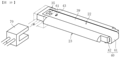
図7は、本実施形態(第1実施形態)に係るヒータ22をヒータフォルダ23から分離した状態を示す斜視図である。
なお、図7において、抵抗発熱体31、給電線34、第1絶縁層32及び第2絶縁層33は省略されている。また、図7に示すように、本実施形態では、ヒータ22及びヒータフォルダ23が一方向に長い板状に形成されていることから、以下のヒータ22及びヒータフォルダ23に関する説明において、これらが長く延びる方向(図7中のX方向)を長手方向とし、この長手方向と直交し定着ベルト20に対するヒータ22の接触面39aと平行な方向(図7中のY方向)を短手方向とし、長手方向及び短手方向の両方向と直交する方向(図7中のZ方向)を厚さ方向として説明する。
FIG. 7 is a perspective view showing a state in which the heater 22 according to the present embodiment (first embodiment) is separated from the heater folder 23. As shown in FIG.
7, the resistance heating element 31, the power supply line 34, the first insulating layer 32 and the second insulating layer 33 are omitted. Further, as shown in FIG. 7, in the present embodiment, the heater 22 and the heater folder 23 are formed in a plate shape elongated in one direction. The extending direction (the X direction in FIG. 7) is defined as the longitudinal direction, and the direction perpendicular to the longitudinal direction and parallel to the contact surface 39a of the heater 22 with respect to the fixing belt 20 (the Y direction in FIG. 7) is defined as the lateral direction. A direction (the Z direction in FIG. 7) perpendicular to both the direction and the width direction will be described as the thickness direction.

図7に示すように、ヒータ22の基材30は、矩形(長方形)の平板状に形成された本体部39と、本体部の長手方向の一端部に屈曲するように設けられた曲げ部40とで構成されている。本体部39において、電極35や抵抗発熱体31等が設けられている面は、被加熱部材である定着ベルト20に対して接触する接触面39aである。曲げ部40は、本体部39の長手方向の一端部からヒータフォルダ23に対するヒータ22の離間方向Aとは反対方向へ屈曲するように設けられた第1曲げ部41と、第1曲げ部41からこれとは交差する方向の電極35側へ屈曲するように設けられた第2曲げ部42とで構成されている。ここで、「離間方向」とは、ヒータ22の接触面39aに垂直な方向、すなわち厚さ方向であって、ヒータ22がヒータフォルダ23から離間する方向を意味する。 As shown in FIG. 7, the base material 30 of the heater 22 includes a body portion 39 formed in a rectangular (rectangular) flat plate shape, and a bent portion 40 provided to bend at one end portion in the longitudinal direction of the body portion. It consists of In the body portion 39, the surface on which the electrode 35, the resistance heating element 31, and the like are provided is a contact surface 39a that contacts the fixing belt 20, which is a member to be heated. The bent portion 40 includes a first bent portion 41 that is bent from one longitudinal end portion of the main body portion 39 in a direction opposite to the separation direction A of the heater 22 from the heater folder 23 , and A second bending portion 42 is provided so as to bend toward the electrode 35 in a direction intersecting with this. Here, the “separation direction” means a direction perpendicular to the contact surface 39 a of the heater 22 , that is, the thickness direction, and the direction in which the heater 22 is separated from the heater holder 23 .

一方、ヒータフォルダ23のヒータ22に対向する面には、基材30の本体部39が収容される凹部60が形成されている。凹部60は、基材30の本体部39とほぼ同等のサイズの矩形(長方形)状に形成された底面部60aと、底面部60aに対して垂直方向に設けられた3つの側面部60b,60c,60dとで構成されている。凹部60の一方の短辺側には側面部が設けられておらず、長手方向に向かって開口する長手方向開口部60eが形成されている。 On the other hand, the surface of the heater folder 23 facing the heater 22 is formed with a concave portion 60 in which the body portion 39 of the base material 30 is accommodated. The recessed portion 60 has a bottom portion 60a formed in a rectangular (rectangular) shape having substantially the same size as the main body portion 39 of the base material 30, and three side portions 60b and 60c provided perpendicularly to the bottom portion 60a. , 60d. No side surface is provided on one short side of the concave portion 60, and a longitudinal opening 60e that opens in the longitudinal direction is formed.

また、凹部60の長手方向開口部60eとは反対側には、ヒータ22の位置決めを行う突起61が設けられている。一方、ヒータ22の本体部39には、ヒータフォルダ23の突起61と係合する位置決め部としての位置決め孔43が形成されている。本実施形態では、位置決め孔43が、ヒータ22の短手方向に長く形成された長方形の孔で構成されている。なお、本実施形態とは反対に、位置決め部としての突起をヒータ22側に設け、この突起と係合する位置決め孔をヒータフォルダ23側に設けてもよい。また、位置決め孔は、貫通孔に限らず、底部を有する孔であってもよい。 A projection 61 for positioning the heater 22 is provided on the opposite side of the recess 60 from the longitudinal opening 60e. On the other hand, the body portion 39 of the heater 22 is formed with a positioning hole 43 as a positioning portion that engages with the protrusion 61 of the heater folder 23 . In this embodiment, the positioning hole 43 is a rectangular hole elongated in the widthwise direction of the heater 22 . Contrary to the present embodiment, a protrusion as a positioning portion may be provided on the heater 22 side, and a positioning hole engaging with this protrusion may be provided on the heater holder 23 side. Moreover, the positioning hole is not limited to a through hole, and may be a hole having a bottom.

次に、ヒータフォルダ23に対するヒータ22の取付方法について説明する。 Next, a method of attaching the heater 22 to the heater folder 23 will be described.

まず、図8に示すように、ヒータ22をヒータフォルダ23に対して長手方向に接近させ、ヒータ22の曲げ部40をヒータフォルダ23の長手方向開口部60e側の端部に係合させる。このとき、本実施形態のように、第2曲げ部42の先端側が斜めに形成されていると、第2曲げ部42の先端側がヒータフォルダ23の背面(離間方向Aとは反対方向を向く面)に対して干渉しにくくなるので、係合が行いやすい。そして、ヒータ22の曲げ部40とヒータフォルダ23の長手方向開口部60e側の端部とが係合する係合箇所を支点に、図9に示すように、ヒータ22を矢印方向に回転させ、ヒータ22の位置決め孔43内にヒータフォルダ23の突起61が挿入されるように、ヒータ22をヒータフォルダ23の凹部60内に収容する。この状態で、突起61と位置決め孔43との係合により、ヒータフォルダ23に対するヒータ22の長手方向の移動が規制される。 First, as shown in FIG. 8, the heater 22 is brought closer to the heater folder 23 in the longitudinal direction, and the bent portion 40 of the heater 22 is engaged with the end of the heater folder 23 on the longitudinal opening 60e side. At this time, if the tip end side of the second bent portion 42 is obliquely formed as in the present embodiment, the tip end side of the second bent portion 42 is the back surface of the heater folder 23 (the surface facing in the direction opposite to the separation direction A). ), it is easy to engage. Then, the heater 22 is rotated in the direction of the arrow as shown in FIG. The heater 22 is accommodated in the recess 60 of the heater folder 23 so that the protrusion 61 of the heater folder 23 is inserted into the positioning hole 43 of the heater 22 . In this state, the projection 61 is engaged with the positioning hole 43 to restrict the movement of the heater 22 in the longitudinal direction with respect to the heater folder 23 .

また、ヒータ22の曲げ部40がヒータフォルダ23の長手方向開口部60c側の端部に係合することで、曲げ部40側でのヒータフォルダ23に対するヒータ22の離間方向Aの移動が規制される。すなわち、本実施形態では、曲げ部40を構成する第1曲げ部41と第2曲げ部42のうち、第2曲げ部42の離間方向Aを向く面420(図7、図9における上面)が、ヒータフォルダ23の離間方向Aとは反対方向を向く面23b(図7、図9における下面)に対して係合することで、ヒータフォルダ23に対するヒータ22の離間方向Aの移動を規制する離間規制部として機能する。 In addition, since the bent portion 40 of the heater 22 is engaged with the end portion of the heater folder 23 on the side of the longitudinal opening 60c, movement of the heater 22 in the separating direction A from the heater folder 23 on the bent portion 40 side is restricted. be. That is, in the present embodiment, of the first bent portion 41 and the second bent portion 42 that constitute the bent portion 40, the surface 420 (upper surface in FIGS. 7 and 9) facing the separation direction A of the second bent portion 42 is , and a surface 23b (lower surface in FIGS. 7 and 9) of the heater folder 23 facing in the opposite direction to the separation direction A, thereby restricting the movement of the heater 22 in the separation direction A with respect to the heater folder 23. Acts as a regulator.

最後に、図10に示すように、ヒータ22とヒータフォルダ23とが組み付けられた状態で、ヒータ22の電極35側の端部にコネクタ70を装着し、コネクタ70によってヒータ22とヒータフォルダ23とを挟持する。これにより、コネクタ70の接触端子とヒータ22の電極35とが電気的に接続されると共に、曲げ部40側と反対側の端部においてヒータ22がヒータフォルダ23に対して固定される。すなわち、ヒータ22は、その一端部側の曲げ部40による係合と、他端部側のコネクタ70による挟持とによって、ヒータフォルダ23から離間方向Aへ離間しないように保持される。このように、ヒータフォルダ23に対するヒータ22の離間が規制されることで、例えば、紙詰まり処理時などでニップ部Nの加圧を解除したときに、ヒータ22へ振動付与されたとしても、ヒータフォルダ23に対するヒータ22の離間方向Aへの脱落(離間)が防止される。 Finally, as shown in FIG. 10, with the heater 22 and the heater holder 23 assembled together, the connector 70 is attached to the end of the heater 22 on the electrode 35 side. sandwiched. As a result, the contact terminals of the connector 70 and the electrodes 35 of the heater 22 are electrically connected, and the heater 22 is fixed to the heater holder 23 at the end opposite to the bent portion 40 side. That is, the heater 22 is held so as not to be separated from the heater holder 23 in the separating direction A by the engagement by the bent portion 40 on the one end side and the sandwiching by the connector 70 on the other end side. By regulating the separation of the heater 22 from the heater folder 23 in this way, even if the heater 22 is vibrated when the pressurization of the nip portion N is released, for example, when handling a paper jam, the heater Detachment (separation) of the heater 22 from the folder 23 in the separation direction A is prevented.

なお、ヒータフォルダ23に対するヒータ22の短手方向の位置決めは、加圧ローラ21の回転に伴って定着ベルト20が回転した際に、ヒータ22が定着ベルト20によってベルト回転方向の下流側へ付勢されることでなされる。すなわち、本実施形態では、ヒータ22の位置決め孔43が短手方向に長い孔で構成されているので、ヒータ22はベルト回転方向の下流側への移動が許容される。そして、ヒータ22がヒータフォルダ23の凹部60を構成する長辺側面部60c,60dの一方(ベルト回転方向の下流側)に突き当たることで移動が規制され、短手方向の位置決めがなされる。なお、この短手方向の位置決めも含めて、接触面39aと平行な任意の方向の位置決めを、上記位置決め孔43と上記突起61との係合によって行ってもよい。 The positioning of the heater 22 in the lateral direction with respect to the heater folder 23 is such that when the fixing belt 20 rotates with the rotation of the pressure roller 21, the heater 22 is urged downstream in the belt rotation direction by the fixing belt 20. It is done by being done. That is, in the present embodiment, since the positioning hole 43 of the heater 22 is configured as a hole elongated in the lateral direction, the heater 22 is allowed to move downstream in the belt rotation direction. When the heater 22 abuts against one of the long side portions 60c and 60d (downstream side in the belt rotation direction) of the recess 60 of the heater folder 23, the heater 22 is restricted in movement and positioned in the width direction. Positioning in any direction parallel to the contact surface 39a, including positioning in the lateral direction, may be performed by engaging the positioning hole 43 and the protrusion 61. FIG.

以上のように、本実施形態に係る構成によれば、ヒータ22の長手方向の一端部に、ヒータフォルダ23と係合して、ヒータフォルダ23に対するヒータ22の離間方向Aの移動を規制する離間規制部420が設けられているので、ヒータクリップ等の別部材を設けなくても、長手方向の一端部側でのヒータフォルダ23に対するヒータ22の離間を規制することができる。これにより、部品点数を少なくすることができるので、低コスト化を図れるようになる。また、ヒータクリップ等の別部材を用いてヒータ22をヒータフォルダ23に保持する場合に比べて、取付作業も楽になる。特に、本実施形態では、ヒータフォルダ23に対するヒータ22の取り付けを、曲げ部40とヒータフォルダ23との係合箇所を支点にヒータ22を回転させることで行えるので、取付作業をスムーズにかつ簡単に行うことが可能である。 As described above, according to the configuration of the present embodiment, one end portion of the heater 22 in the longitudinal direction is engaged with the heater folder 23 to restrict the movement of the heater 22 in the separation direction A with respect to the heater folder 23 . Since the regulating portion 420 is provided, it is possible to regulate the separation of the heater 22 from the heater holder 23 at one end in the longitudinal direction without providing a separate member such as a heater clip. As a result, the number of parts can be reduced, so that the cost can be reduced. Moreover, the attachment work is easier than when the heater 22 is held in the heater holder 23 using a separate member such as a heater clip. In particular, in the present embodiment, the heater 22 can be attached to the heater folder 23 by rotating the heater 22 around the engagement point between the bent portion 40 and the heater folder 23, so that the attachment work can be performed smoothly and easily. It is possible.

また、本実施形態では、ヒータ22の曲げ部40(第1曲げ部41)が、本体部39から定着ベルト20側(ニップ部N側)とは反対側へ曲げられるように形成されているので、定着ベルト20に対して曲げ部40が干渉しにくくなる。また、ヒータ22を定着ベルト20内に配置するときの組み付け作業も行いやすくなる。 Further, in the present embodiment, the bent portion 40 (first bent portion 41) of the heater 22 is formed so as to be bent from the body portion 39 to the side opposite to the fixing belt 20 side (nip portion N side). , the bent portion 40 is less likely to interfere with the fixing belt 20 . In addition, it becomes easy to perform the assembly work when arranging the heater 22 in the fixing belt 20 .

上述のように、ヒータ22の基材30の材料は、金属材料のほかに、ガラス、セラミック等の塑性材料を用いることが可能であるが、加工のしやすさやコストの面から特に金属材料を用いることが好ましい。基材30を金属材料とすることで、本実施形態のような第1曲げ部41及び第2曲げ部42を有する構成においても、これらの曲げ部41,42の形成を容易に行うことができる。 As described above, the material of the base material 30 of the heater 22 can be plastic materials such as glass and ceramics in addition to metal materials. It is preferable to use By using a metal material for the base material 30, even in a configuration having the first bent portion 41 and the second bent portion 42 as in the present embodiment, the bent portions 41 and 42 can be easily formed. .

なお、本実施形態では、第1絶縁層32や第2絶縁層33の形成を、基材30上に絶縁材料を膜状に吹き付けることにより行っている。しかしながら、この方法では、本体部39に対して高さ(厚さ方向に位置)が異なる曲げ部41に対する絶縁層の形成が難しい。従って、本実施形態では、各絶縁層32,33を本体部39のみに設け、曲げ部41には設けていない。 In this embodiment, the first insulating layer 32 and the second insulating layer 33 are formed by spraying an insulating material onto the substrate 30 in a film form. However, with this method, it is difficult to form an insulating layer for the bent portion 41 that is different in height (position in the thickness direction) from the body portion 39 . Therefore, in this embodiment, the insulating layers 32 and 33 are provided only on the main body portion 39 and not provided on the bent portion 41 .

以下、上述の実施形態とは異なる実施形態について説明する。なお、以下の実施形態については、上述の実施形態とは異なる部分を中心に説明し、それ以外の部分は基本的に同様であるので説明を省略する。 Embodiments different from the above-described embodiments will be described below. Note that the following embodiment will be described with a focus on the parts that are different from the above-described embodiment, and the other parts will be omitted because they are basically the same.

図11は、本発明の第2実施形態に係るヒータ22及びヒータフォルダ23の斜視図である。
なお、図11中のX方向、Y方向、Z方向は、上述と同様に、長手方向、短手方向、厚さ方向を示す。また、以下の説明で参照する図面においても同様である。
FIG. 11 is a perspective view of the heater 22 and heater holder 23 according to the second embodiment of the invention.
Note that the X direction, Y direction, and Z direction in FIG. 11 indicate the longitudinal direction, the lateral direction, and the thickness direction, as described above. The same applies to the drawings referred to in the following description.

図11に示す本発明の第2実施形態では、ヒータ22の長手方向の一端部側に設けられた曲げ部40が、第1曲げ部41だけで構成されている。すなわち、本実施形態に係る曲げ部41は、上述の第2曲げ部42は有していない。また、本実施形態では、第1曲げ部41に孔部44が設けられている。一方、ヒータフォルダ23の長手方向開口部60e側の端部には、ヒータ22の長手方向に突出する凸部62が設けられている。 In the second embodiment of the present invention shown in FIG. 11, the bent portion 40 provided at one end in the longitudinal direction of the heater 22 is composed only of the first bent portion 41 . That is, the bent portion 41 according to the present embodiment does not have the second bent portion 42 described above. Further, in the present embodiment, a hole portion 44 is provided in the first bent portion 41 . On the other hand, a projection 62 projecting in the longitudinal direction of the heater 22 is provided at the end of the heater folder 23 on the side of the longitudinal opening 60e.

この第2実施形態において、ヒータ22の取り付けを行う場合は、図12に示すように、まず、ヒータ22の第1曲げ部41に設けられた孔部44にヒータフォルダ23の凸部62が挿入されるようにして、互いに係合させる。そして、孔部44と凸部62とが互いに係合する係合箇所を支点に、図13に示すように、ヒータ22を矢印方向に回転させる。これにより、ヒータ22がヒータフォルダ23の凹部60内に収容され、ヒータフォルダ23の突起61がヒータ22の位置決め孔43内に挿入される。そして、上述の実施形態と同様に、ヒータ22の電極35側の端部に、コネクタ70を装着する。 In the second embodiment, when the heater 22 is attached, first, as shown in FIG. so as to engage each other. Then, the heater 22 is rotated in the direction of the arrow, as shown in FIG. As a result, the heater 22 is housed in the recess 60 of the heater folder 23 , and the protrusion 61 of the heater folder 23 is inserted into the positioning hole 43 of the heater 22 . Then, the connector 70 is attached to the end of the heater 22 on the electrode 35 side in the same manner as in the above-described embodiment.

このように、ヒータ22がヒータフォルダ23に保持された状態では、ヒータ22の孔部44とヒータフォルダ23の凸部62とが互いに係合することで、ヒータフォルダ23に対するヒータ22の離間方向Aの移動が規制される。すなわち、本実施形態では、ヒータ22の孔部44を構成する面のうち、離間方向Aを向く面440(図11、図13参照)が、凸部62における離間方向Aとは反対方向を向く面(被係合部)に対して係合してヒータ22の離間方向Aの移動を規制する離間規制部として機能する。 In this way, when the heater 22 is held by the heater folder 23 , the holes 44 of the heater 22 and the projections 62 of the heater folder 23 are engaged with each other. movement is restricted. That is, in the present embodiment, of the surfaces forming the hole portion 44 of the heater 22, the surface 440 facing the separation direction A (see FIGS. 11 and 13) faces the opposite direction to the separation direction A of the convex portion 62. It functions as a separation restricting portion that engages with a surface (engaged portion) to restrict movement of the heater 22 in the separation direction A.

また、図14に示す例のように、上述の構成とは反対に、ヒータ22側に(例えば、エンボス加工などにより)長手方向に突出する凸部47設け、ヒータフォルダ23側に長手方向に凹む孔部63を設けてもよい。この場合も、孔部63と凸部47との係合によりヒータ22の離間方向Aの移動を規制することができる。なお、ヒータ22に設けられる孔部44又はヒータフォルダ23に設けられる孔部63は、貫通孔に限らず、底部を有する孔であってもよい。 Further, as in the example shown in FIG. 14, opposite to the above configuration, a projection 47 projecting in the longitudinal direction is provided on the heater 22 side (for example, by embossing), and the heater folder 23 side is recessed in the longitudinal direction. A hole 63 may be provided. Also in this case, the movement of the heater 22 in the separating direction A can be restricted by the engagement between the hole 63 and the projection 47 . The hole 44 provided in the heater 22 or the hole 63 provided in the heater folder 23 is not limited to a through hole, and may be a hole having a bottom.

また、本実施形態においても、上述の図7~図10に示す第1実施形態と同様に、ヒータ22の第1曲げ部41が、本体部39から定着ベルト20側(ニップ部N側)とは反対側へ曲げられるように形成されているので、定着ベルト20に対して曲げ部40が干渉しにくくなり、ヒータ22の組み付け作業も行いやすくなる。さらに、本実施形態では、第1実施形態に比べて第2曲げ部42を設けない分、基材30の長さを短くすることができるため、低コストでありながら同等の効果を奏することが可能である。また、基材30の長さが短くなることで、基材30の低熱容量化が図られ、省エネ性も向上する。 Also in this embodiment, as in the first embodiment shown in FIGS. 7 to 10, the first bent portion 41 of the heater 22 extends from the body portion 39 to the fixing belt 20 side (nip portion N side). are formed to be bent in the opposite direction, the bent portion 40 is less likely to interfere with the fixing belt 20, and the heater 22 can be easily assembled. Furthermore, in the present embodiment, the length of the base material 30 can be shortened by the amount corresponding to the absence of the second bent portion 42 compared to the first embodiment, so that the same effect can be achieved while the cost is low. It is possible. Moreover, since the length of the base material 30 is shortened, the heat capacity of the base material 30 can be reduced, and the energy saving performance can be improved.

図15は、本発明の第3実施形態に係るヒータ22及びヒータフォルダ23の斜視図である。 FIG. 15 is a perspective view of the heater 22 and heater holder 23 according to the third embodiment of the invention.

図15に示す第3実施形態では、ヒータ22の本体部39が、その長手方向の一端部において、本体部39と同一面上で短手方向の一方に突出する突片部39bを有している。なお、ここでいう「同一面上」とは、本体部39の互いに交差する3方向の面のうち、最も広く形成された面に対する同一面上を意味する。また、以下で述べる「同一面上」も同様に解釈するものとする。 In the third embodiment shown in FIG. 15, the body portion 39 of the heater 22 has a projecting piece portion 39b projecting in one of the width directions on the same plane as the body portion 39 at one end portion in the longitudinal direction. there is It should be noted that the term “on the same plane” as used herein means on the same plane with respect to the widest plane among the planes of the three mutually intersecting directions of the body portion 39 . In addition, "on the same plane" described below shall be similarly interpreted.

また、本実施形態では、本体部39の突片部39bに曲げ部40が設けられている。この曲げ部40は、突片部39bからヒータ22の離間方向Aとは反対方向へ屈曲する第1曲げ部41と、第1曲げ部41から本体部39の電極35側へ屈曲する第2曲げ部42とで構成されている。一方、ヒータフォルダ23には、その長手方向開口部60e側の端部の近傍に短手方向に突出する凸部62が設けられている。また、ヒータフォルダ23の長手方向開口部60側では、本体部39の突片部39bとの干渉を回避するため、凹部60を構成する一方の長辺側面部60cの一部が切り欠かれた形状に形成され、短手方向に開口する短手方向開口部60fが形成されている。 Further, in the present embodiment, a bent portion 40 is provided on the projecting piece portion 39b of the main body portion 39. As shown in FIG. The bent portion 40 includes a first bent portion 41 that is bent in a direction opposite to the separation direction A of the heater 22 from the projecting piece portion 39b, and a second bent portion that is bent from the first bent portion 41 toward the electrode 35 side of the body portion 39. 42. On the other hand, the heater folder 23 is provided with a protrusion 62 protruding in the lateral direction near the end on the side of the longitudinal opening 60e. Further, on the side of the longitudinal opening 60 of the heater folder 23, a part of one long side surface 60c constituting the recess 60 is notched in order to avoid interference with the projecting piece 39b of the main body 39. A lateral direction opening 60f is formed in a shape and is open in the lateral direction.

この第3実施形態において、ヒータ22の取り付けを行う場合は、図16に示すように、まず、ヒータ22の曲げ部40をヒータフォルダ23の長手方向開口部60c側に設けられた凸部62に対して係合させる。そして、ヒータ22の曲げ部40とヒータフォルダ23の凸部62とが係合する係合箇所を支点に、図17に示すように、ヒータ22を矢印方向に回転させる。これにより、ヒータ22がヒータフォルダ23の凹部60内に収容され、ヒータフォルダ23の突起61がヒータ22の位置決め孔43内に挿入される。そして、上述の実施形態と同様に、ヒータ22の電極35側の端部に、コネクタ70を装着する。 In this third embodiment, when mounting the heater 22, as shown in FIG. engage against. Then, the heater 22 is rotated in the direction of the arrow as shown in FIG. As a result, the heater 22 is housed in the recess 60 of the heater folder 23 , and the protrusion 61 of the heater folder 23 is inserted into the positioning hole 43 of the heater 22 . Then, the connector 70 is attached to the end of the heater 22 on the electrode 35 side in the same manner as in the above-described embodiment.

このように、ヒータ22がヒータフォルダ23に保持された状態では、ヒータ22の曲げ部40とヒータフォルダ23の凸部62とが互いに係合することで、ヒータフォルダ23に対するヒータ22の離間方向Aの移動が規制される。すなわち、本実施形態では、ヒータ22の曲げ部40のうち、第2曲げ部42の離間方向Aを向く面420(図15、図16参照)が、凸部62における離間方向Aとは反対方向を向く面(被係合部)に対して係合してヒータ22の離間方向Aの移動を規制する離間規制部として機能する。 In this way, when the heater 22 is held by the heater folder 23, the bent portion 40 of the heater 22 and the convex portion 62 of the heater folder 23 are engaged with each other, so that the separation direction A of the heater 22 from the heater folder 23 movement is restricted. That is, in the present embodiment, of the bent portion 40 of the heater 22 , the surface 420 (see FIGS. 15 and 16) of the bent portion 40 facing the separation direction A of the second bent portion 42 faces the direction opposite to the separation direction A of the convex portion 62 . function as a separation restricting portion that engages with the surface (engaged portion) facing the direction to restrict the movement of the heater 22 in the separation direction A.

また、本実施形態においても、上述の各実施形態と同様に、ヒータ22の第1曲げ部41は、本体部39から定着ベルト20側(ニップ部N側)とは反対側へ曲げられるように形成されているので、定着ベルト20に対して曲げ部40が干渉しにくくなり、ヒータ22の組み付け作業も行いやすくなる。また、本実施形態では、曲げ部40が本体部39の短手方向外側に設けられていることで、上述の各実施形態に比べて、短手方向ではヒータ22のサイズが大きくなるが、長手方向ではヒータ22のサイズを小さくすることが可能である。さらに、本実施形態では、曲げ部40が小さく形成されていることで、基材30の低熱容量化が図られ、省エネ性も向上する。 Also in this embodiment, similarly to the above-described embodiments, the first bent portion 41 of the heater 22 is bent from the body portion 39 to the side opposite to the fixing belt 20 side (nip portion N side). Since it is formed, the bent portion 40 is less likely to interfere with the fixing belt 20, and the work of assembling the heater 22 is facilitated. In addition, in the present embodiment, the bent portion 40 is provided on the outer side of the main body portion 39 in the widthwise direction. It is possible to reduce the size of the heater 22 in the direction. Furthermore, in the present embodiment, since the bent portion 40 is formed small, the heat capacity of the base material 30 can be reduced, and the energy saving performance can also be improved.

また、図18に示す例のように、ヒータ22がヒータフォルダ23に対して取り付けられた状態で、ヒータ22の第2曲げ部42(離間規制部)とヒータフォルダ23の凸部62(被係合部)との間に隙間S(ガタ)があるように構成してもよい。この場合、ヒータフォルダ23に対するヒータ22の取付作業が行いやすくなる。 18, in a state where the heater 22 is attached to the heater folder 23, the second bent portion 42 (separation regulation portion) of the heater 22 and the convex portion 62 (receiving portion) of the heater folder 23 are arranged. It may be configured so that there is a gap S (backlash) between the joint portion). In this case, the work of attaching the heater 22 to the heater folder 23 is facilitated.

また反対に、図19に示す例のように、ヒータ22の第2曲げ部42(離間規制部)とヒータフォルダ23の凸部62(被係合部)との間に隙間S(ガタ)を設けず、第2曲げ部42と凸部62の少なくとも一方が弾性変形しながら互いに接触するようにしてもよい。この場合、弾性力を利用してヒータフォルダ23に対するヒータ22の密着性を高めることができる。なお、このような離間規制部と被係合部との間での、隙間Sを介在させるか、あるいは弾性変形させて密着させるかは、他の実施形態においても適宜選択して適用することが可能である。 On the contrary, as in the example shown in FIG. 19, a gap S (backlash) is provided between the second bent portion 42 (separation regulation portion) of the heater 22 and the convex portion 62 (engaged portion) of the heater holder 23. Instead, at least one of the second bent portion 42 and the convex portion 62 may contact each other while elastically deforming. In this case, it is possible to increase the adhesion of the heater 22 to the heater holder 23 by utilizing the elastic force. It should be noted that whether a gap S is interposed between the separation regulating portion and the engaged portion or whether they are brought into close contact with each other by elastic deformation can be appropriately selected and applied to other embodiments as well. It is possible.

図20は、本発明の第4実施形態に係るヒータ22及びヒータフォルダ23の斜視図である。 FIG. 20 is a perspective view of the heater 22 and heater holder 23 according to the fourth embodiment of the invention.

図20に示す第4実施形態では、ヒータ22の本体部39が、その長手方向の一端部において、本体部39と同一面上で長手方向に突出する突片部39bを有している。そして、この突片部39bに、突片部39bからヒータ22の離間方向Aとは反対方向へ屈曲する第1曲げ部41と、第1曲げ部41から本体部39の電極35側とは反対側へ屈曲する第2曲げ部42と、から成る曲げ部40が設けられている。一方、ヒータフォルダ23に設けられた凹部60の底面部60aには、孔部64が形成されている。この孔部64は、ヒータ22の曲げ部40と対応するように長手方向の一端部側に設けられている。また、凹部60の長手方向一端部側は、長手方向に開口しておらず(上述の長手方向開口部60eが形成されておらず)、側面部60gが設けられている。 In the fourth embodiment shown in FIG. 20, the body portion 39 of the heater 22 has a protruding piece portion 39b projecting in the longitudinal direction on the same plane as the body portion 39 at one end portion in the longitudinal direction. A first bent portion 41 that bends from the projected piece portion 39b in a direction opposite to the direction A in which the heater 22 is separated from the projected piece portion 39b and a portion that extends from the first bent portion 41 to the body portion 39 on the side opposite to the electrode 35 side. A bending portion 40 is provided which consists of a second bending portion 42 bending to the side. On the other hand, a hole portion 64 is formed in the bottom portion 60a of the recessed portion 60 provided in the heater folder 23 . The hole 64 is provided at one end in the longitudinal direction so as to correspond to the bent portion 40 of the heater 22 . One longitudinal end of the concave portion 60 is not opened in the longitudinal direction (the longitudinal opening 60e is not formed), and a side surface portion 60g is provided.

この第4実施形態において、ヒータ22の取り付けを行う場合は、図21に示すように、まず、ヒータ22の曲げ部40をヒータフォルダ23の凹部60に設けられた孔部64に挿入して係合させる。そして、曲げ部40と孔部64とが係合する係合箇所を支点に、図22に示すように、ヒータ22を矢印方向に回転させる。これにより、ヒータ22がヒータフォルダ23の凹部60内に収容され、ヒータフォルダ23の突起61がヒータ22の位置決め孔43内に挿入される。そして、上述の実施形態と同様に、ヒータ22の電極35側の端部に、コネクタ70を装着する。 In this fourth embodiment, when mounting the heater 22, as shown in FIG. match. Then, the heater 22 is rotated in the direction of the arrow as shown in FIG. As a result, the heater 22 is housed in the recess 60 of the heater folder 23 , and the protrusion 61 of the heater folder 23 is inserted into the positioning hole 43 of the heater 22 . Then, the connector 70 is attached to the end of the heater 22 on the electrode 35 side in the same manner as in the above-described embodiment.

このように、ヒータ22がヒータフォルダ23に保持された状態では、ヒータ22の曲げ部40がヒータフォルダ23の孔部64に挿入され、曲げ部40の先端部がヒータフォルダ23の背面(離間方向Aとは反対方向を向く面)に係合することで、ヒータフォルダ23に対するヒータ22の離間方向Aの移動が規制される。すなわち、本実施形態では、ヒータ22の曲げ部40のうち、第2曲げ部42の離間方向Aを向く面420(図20、図22参照)が、ヒータフォルダ23の離間方向Aとは反対方向を向く面(被係合部)に対して係合してヒータ22の離間方向Aの移動を規制する離間規制部として機能する。 In this way, when the heater 22 is held by the heater holder 23, the bent portion 40 of the heater 22 is inserted into the hole 64 of the heater folder 23, and the tip of the bent portion 40 is positioned on the back surface of the heater folder 23 (separation direction). A) restricts the movement of the heater 22 in the separation direction A with respect to the heater folder 23 . That is, in the present embodiment, of the bent portion 40 of the heater 22, the surface 420 (see FIGS. 20 and 22) of the bent portion 40 facing the separation direction A of the second bent portion 42 faces the direction opposite to the separation direction A of the heater folder 23. function as a separation restricting portion that engages with the surface (engaged portion) facing the direction to restrict the movement of the heater 22 in the separation direction A.

また、本実施形態においても、上述の各実施形態と同様に、ヒータ22の第1曲げ部41が、本体部39から定着ベルト20側(ニップ部N側)とは反対側へ曲げられるように形成されているので、定着ベルト20に対して曲げ部40が干渉しにくくなり、ヒータ22の組み付け作業も行いやすくなる。さらに、本実施形態では、曲げ部40が小さく形成されることで、基材30の低熱容量化が図られ、省エネ性も向上する。 Also in this embodiment, as in the above-described embodiments, the first bent portion 41 of the heater 22 is bent from the body portion 39 to the side opposite to the fixing belt 20 side (nip portion N side). Since it is formed, the bent portion 40 is less likely to interfere with the fixing belt 20, and the work of assembling the heater 22 is facilitated. Furthermore, in the present embodiment, since the bent portion 40 is formed small, the heat capacity of the base material 30 can be reduced, and the energy saving performance can be improved.

図23は、本発明の第5実施形態に係るヒータ22及びヒータフォルダ23の斜視図である。 FIG. 23 is a perspective view of the heater 22 and heater holder 23 according to the fifth embodiment of the invention.

図23に示す第5実施形態では、上述の図20~図22に示す第4実施形態と同様に、本体部39の長手方向に突出する突片部39bに曲げ部40が設けられている。ただし、第4実施形態とは異なり、第2曲げ部42は、第1曲げ部41から本体部39の電極35側へ屈曲するように設けられている。一方、ヒータフォルダ23の長手方向開口部60e側の端部には、長手方向(長手方向開口部60e側とは反対側)と厚さ方向(離間方向A)へ凹む孔部63が設けられている。 In the fifth embodiment shown in FIG. 23, similarly to the fourth embodiment shown in FIGS. 20 to 22, a projecting piece 39b protruding in the longitudinal direction of the main body 39 is provided with a bent portion 40. As shown in FIG. However, unlike the fourth embodiment, the second bent portion 42 is provided so as to bend from the first bent portion 41 toward the electrode 35 side of the body portion 39 . On the other hand, at the end of the heater folder 23 on the side of the longitudinal opening 60e, a hole 63 is provided which is recessed in the longitudinal direction (the side opposite to the longitudinal opening 60e) and in the thickness direction (separation direction A). there is

この第5実施形態において、ヒータ22の取り付けを行う場合は、図24に示すように、まず、ヒータ22の曲げ部40をヒータフォルダ23の孔部63に挿入して係合させる。そして、曲げ部40と孔部63とが係合する係合箇所を支点に、図24に示すように、ヒータ22を矢印方向に回転させる。これにより、ヒータ22がヒータフォルダ23の凹部60内に収容され、ヒータフォルダ23の突起61がヒータ22の位置決め孔43内に挿入される。そして、上述の実施形態と同様に、ヒータ22の電極35側の端部に、コネクタ70を装着する。 In the fifth embodiment, when the heater 22 is attached, first, the bent portion 40 of the heater 22 is inserted into the hole 63 of the heater holder 23 and engaged therewith, as shown in FIG. Then, the heater 22 is rotated in the direction of the arrow as shown in FIG. As a result, the heater 22 is housed in the recess 60 of the heater folder 23 , and the protrusion 61 of the heater folder 23 is inserted into the positioning hole 43 of the heater 22 . Then, the connector 70 is attached to the end of the heater 22 on the electrode 35 side in the same manner as in the above-described embodiment.

このように、ヒータ22がヒータフォルダ23に保持された状態では、ヒータ22の曲げ部40がヒータフォルダ23の孔部63に挿入され、曲げ部40の先端部が孔部63に係合することで、ヒータフォルダ23に対するヒータ22の離間方向Aの移動が規制される。すなわち、本実施形態では、ヒータ22の曲げ部40のうち、第2曲げ部42の離間方向Aを向く面420(図23、図25参照)が、孔部63における離間方向Aとは反対方向を向く面(被係合部)に対して係合してヒータ22の離間方向Aの移動を規制する離間規制部として機能する。 In this way, when the heater 22 is held by the heater holder 23 , the bent portion 40 of the heater 22 is inserted into the hole 63 of the heater folder 23 and the tip of the bent portion 40 is engaged with the hole 63 . , the movement of the heater 22 in the separation direction A with respect to the heater folder 23 is regulated. That is, in the present embodiment, of the bent portion 40 of the heater 22 , the surface 420 (see FIGS. 23 and 25) of the bent portion 40 facing the separation direction A of the second bent portion 42 faces the direction opposite to the separation direction A of the hole portion 63 . function as a separation restricting portion that engages with the surface (engaged portion) facing the direction to restrict the movement of the heater 22 in the separation direction A.

また、本実施形態においても、上述の各実施形態と同様に、ヒータ22の第1曲げ部41が、本体部39から定着ベルト20側(ニップ部N側)とは反対側へ曲げられるように形成されているので、定着ベルト20に対して曲げ部40が干渉しにくくなり、ヒータ22の組み付け作業も行いやすくなる。さらに、本実施形態では、曲げ部40が小さく形成されていることで、基材30の低熱容量化が図られ、省エネ性も向上する。 Also in this embodiment, as in the above-described embodiments, the first bent portion 41 of the heater 22 is bent from the body portion 39 to the side opposite to the fixing belt 20 side (nip portion N side). Since it is formed, the bent portion 40 is less likely to interfere with the fixing belt 20, and the work of assembling the heater 22 is facilitated. Furthermore, in the present embodiment, since the bent portion 40 is formed small, the heat capacity of the base material 30 can be reduced, and the energy saving performance can also be improved.

また、図26に示す本実施形態の変形例のように、さらに、第2曲げ部42に、これとは交差する方向へ屈曲する第3曲げ部45を設けてもよい。この場合、第3曲げ部45が、その先端に向かって本体部39から離れるように傾斜していることで、第3曲げ部45を孔部63に挿入する際のガイド部として機能させ、孔部63への曲げ部40の挿入を行いやすくすることができる。 Further, as in the modification of the present embodiment shown in FIG. 26, the second bent portion 42 may be further provided with a third bent portion 45 that is bent in a direction intersecting with the second bent portion 42 . In this case, the third bent portion 45 is inclined away from the main body portion 39 toward the distal end thereof, so that the third bent portion 45 functions as a guide portion when inserting the third bent portion 45 into the hole portion 63 . The insertion of the bent portion 40 into the portion 63 can be facilitated.

図27は、本発明の第6実施形態に係るヒータ22及びヒータフォルダ23の斜視図である。 FIG. 27 is a perspective view of the heater 22 and heater holder 23 according to the sixth embodiment of the invention.

図27に示す第6実施形態では、ヒータ22の本体部39が、その長手方向の一端部において、本体部39と同一面上で短手方向の両方向に突出するように設けられた一対の突片部39bを有している。そして、各突片部39bには、突片部39bからヒータ22の離間方向Aとは反対方向へ屈曲する第1曲げ部41と、第1曲げ部41から短手方向の内側へ屈曲する第2曲げ部42とが設けられている。一方、ヒータフォルダ23の長手方向開口部60側には、上記ヒータ22の一対の突片部39bとの干渉を回避するため、凹部60を構成する各長辺側面部60c,60dの一部が切り欠かれた形状に形成され、短手方向に開口する一対の短手方向開口部60fが形成されている。 In the sixth embodiment shown in FIG. 27, the body portion 39 of the heater 22 has a pair of projections provided at one end portion in the longitudinal direction so as to protrude in both lateral directions on the same plane as the body portion 39 . It has a piece 39b. Each protruding piece 39b has a first bending portion 41 that bends from the protruding piece 39b in a direction opposite to the separation direction A of the heater 22, and a first bending portion 41 that bends inward in the lateral direction from the first bent portion 41. 2 bends 42 are provided. On the other hand, on the side of the longitudinal opening 60 of the heater folder 23, in order to avoid interference with the pair of projecting pieces 39b of the heater 22, parts of the long side surfaces 60c and 60d forming the recess 60 are provided. A pair of lateral direction openings 60f are formed in a notched shape and open in the lateral direction.

この第6実施形態において、ヒータ22の取り付けを行う場合は、図28に示すように、まず、ヒータ22の第1曲げ部41と第2曲げ部42とから成る一対の曲げ部40をヒータフォルダ23の一対の短手方向開口部60f近傍の部分に対して係合させる。そして、曲げ部40と短手方向開口部60f近傍の部分とが係合する係合箇所を支点に、図29に示すように、ヒータ22を矢印方向に回転させる。これにより、ヒータ22がヒータフォルダ23の凹部60内に収容され、ヒータフォルダ23の突起61がヒータ22の位置決め孔43内に挿入される。そして、上述の実施形態と同様に、ヒータ22の電極35側の端部に、コネクタ70を装着する。 In this sixth embodiment, when the heater 22 is attached, first, as shown in FIG. 28, a pair of bent portions 40 consisting of a first bent portion 41 and a second bent portion 42 of the heater 22 is attached to a heater folder. 23 in the vicinity of the pair of lateral openings 60f. Then, the heater 22 is rotated in the direction of the arrow, as shown in FIG. 29, with the engagement point where the bent portion 40 and the portion near the lateral opening 60f engage as a fulcrum. As a result, the heater 22 is housed in the recess 60 of the heater folder 23 , and the protrusion 61 of the heater folder 23 is inserted into the positioning hole 43 of the heater 22 . Then, the connector 70 is attached to the end of the heater 22 on the electrode 35 side in the same manner as in the above-described embodiment.

このように、ヒータ22がヒータフォルダ23に保持された状態では、ヒータ22の各曲げ部40の先端部がヒータフォルダ23の短手方向開口部60f近傍の背面(離間方向Aとは反対方向を向く面)に係合することで、ヒータフォルダ23に対するヒータ22の離間方向Aの移動が規制される。すなわち、本実施形態では、ヒータ22の各曲げ部40のうち、第2曲げ部42の離間方向Aを向く面420(図27、図29参照)が、ヒータフォルダ23の離間方向Aとは反対方向を向く面(被係合部)に対して係合してヒータ22の離間方向Aの移動を規制する離間規制部として機能する。 In this way, when the heater 22 is held by the heater holder 23, the tip of each bent portion 40 of the heater 22 is positioned on the rear surface of the heater folder 23 in the vicinity of the width direction opening 60f (in the direction opposite to the separation direction A). The movement of the heater 22 in the separation direction A with respect to the heater folder 23 is restricted by engaging with the facing surface). That is, in the present embodiment, of the bent portions 40 of the heater 22 , the surface 420 (see FIGS. 27 and 29) facing the separation direction A of the second bent portion 42 is opposite to the separation direction A of the heater folder 23 . It functions as a separation regulating portion that engages with the facing surface (engaged portion) to regulate the movement of the heater 22 in the separation direction A.

また、本実施形態においても、上述の各実施形態と同様に、ヒータ22の第1曲げ部41が、本体部39から定着ベルト20側(ニップ部N側)とは反対側へ曲げられるように形成されているので、定着ベルト20に対して曲げ部40が干渉しにくくなり、ヒータ22の組み付け作業も行いやすくなる。また、本実施形態では、曲げ部40が本体部39の短手方向外側に設けられていることで、短手方向ではヒータ22のサイズが大きくなるが、長手方向ではヒータ22のサイズを小さくすることが可能である。 Also in this embodiment, as in the above-described embodiments, the first bent portion 41 of the heater 22 is bent from the body portion 39 to the side opposite to the fixing belt 20 side (nip portion N side). Since it is formed, the bent portion 40 is less likely to interfere with the fixing belt 20, and the work of assembling the heater 22 is facilitated. In addition, in the present embodiment, since the bent portion 40 is provided on the outer side of the body portion 39 in the lateral direction, the size of the heater 22 is increased in the lateral direction, but the size of the heater 22 is decreased in the longitudinal direction. Is possible.

図30は、本発明の第7実施形態に係るヒータ22及びヒータフォルダ23の斜視図である。 FIG. 30 is a perspective view of the heater 22 and heater holder 23 according to the seventh embodiment of the invention.

図30に示す第7実施形態では、ヒータ22の本体部39が、その長手方向の一端部において、本体部39と同一面上で長手方向に突出する突片部39bを有する。そして、この突片部39bに、突片部39bからヒータ22の離間方向Aとは反対方向へ屈曲する第1曲げ部41と、第1曲げ部41から短手方向へ屈曲する第2曲げ部42と、から成る曲げ部40が設けられている。一方、ヒータフォルダ23の長手方向開口部60e側の端部には、長手方向に突出する凸部62が設けられている。 In the seventh embodiment shown in FIG. 30, a main body portion 39 of a heater 22 has a protruding piece portion 39b that protrudes in the longitudinal direction on the same plane as the main body portion 39 at one end portion in the longitudinal direction. A first bent portion 41 bent from the projected piece portion 39b in a direction opposite to the separation direction A of the heater 22 and a second bent portion bent from the first bent portion 41 in a lateral direction are provided on the projected piece portion 39b. A bend 40 is provided comprising 42 and . On the other hand, a projection 62 protruding in the longitudinal direction is provided at the end of the heater folder 23 on the side of the longitudinal opening 60e.

この第7実施形態において、ヒータ22の取り付けを行う場合は、図31に示すように、まず、ヒータ22の曲げ部40をヒータフォルダ23の凸部62に対して係合させる。そして、曲げ部40と凸部62とが係合する係合箇所を支点に、図32に示すように、ヒータ22を矢印方向に回転させる。これにより、ヒータ22がヒータフォルダ23の凹部60内に収容され、ヒータフォルダ23の突起61がヒータ22の位置決め孔43内に挿入される。そして、上述の実施形態と同様に、ヒータ22の電極35側の端部に、コネクタ70を装着する。 In the seventh embodiment, when the heater 22 is attached, first, the bent portion 40 of the heater 22 is engaged with the convex portion 62 of the heater holder 23, as shown in FIG. Then, the heater 22 is rotated in the direction of the arrow as shown in FIG. As a result, the heater 22 is housed in the recess 60 of the heater folder 23 , and the protrusion 61 of the heater folder 23 is inserted into the positioning hole 43 of the heater 22 . Then, the connector 70 is attached to the end of the heater 22 on the electrode 35 side in the same manner as in the above-described embodiment.

このように、ヒータ22がヒータフォルダ23に保持された状態では、ヒータ22の曲げ部40とヒータフォルダ23の凸部62とが互いに係合することで、ヒータフォルダ23に対するヒータ22の離間方向Aの移動が規制される。すなわち、本実施形態では、ヒータ22の曲げ部40のうち、第2曲げ部42の離間方向Aを向く面420(図30、図32参照)が、凸部62における離間方向Aとは反対方向を向く面(被係合部)に対して係合してヒータ22の離間方向Aの移動を規制する離間規制部として機能する。 In this way, when the heater 22 is held by the heater folder 23, the bent portion 40 of the heater 22 and the convex portion 62 of the heater folder 23 are engaged with each other, so that the separation direction A of the heater 22 from the heater folder 23 movement is restricted. That is, in the present embodiment, of the bent portion 40 of the heater 22 , the surface 420 (see FIGS. 30 and 32) of the bent portion 40 facing the separation direction A of the second bent portion 42 faces the direction opposite to the separation direction A of the convex portion 62 . function as a separation restricting portion that engages with the surface (engaged portion) facing the direction to restrict the movement of the heater 22 in the separation direction A.

また、本実施形態においても、上述の各実施形態と同様に、ヒータ22の第1曲げ部41が、本体部39から定着ベルト20側(ニップ部N側)とは反対側へ曲げられるように形成されているので、定着ベルト20に対して曲げ部40が干渉しにくくなり、ヒータ22の組み付け作業も行いやすくなる。さらに、本実施形態では、曲げ部40が小さく形成されていることで、基材30の低熱容量化が図られ、省エネ性も向上する。 Also in this embodiment, as in the above-described embodiments, the first bent portion 41 of the heater 22 is bent from the body portion 39 to the side opposite to the fixing belt 20 side (nip portion N side). Since it is formed, the bent portion 40 is less likely to interfere with the fixing belt 20, and the work of assembling the heater 22 is facilitated. Furthermore, in the present embodiment, since the bent portion 40 is formed small, the heat capacity of the base material 30 can be reduced, and the energy saving performance can also be improved.

図33は、本発明の第8実施形態に係るヒータ22及びヒータフォルダ23の斜視図である。 FIG. 33 is a perspective view of the heater 22 and heater holder 23 according to the eighth embodiment of the invention.

図33に示す第8実施形態では、ヒータ22の本体部39が、その長手方向の一端部において、本体部39と同一面上で長手方向に突出する一対の突片部39bを有している。そして、各突片部39bには、突片部39bからヒータ22の離間方向Aとは反対方向へ屈曲する一対の第1曲げ部41が設けられ、各第1曲げ部41は、これらから短手方向へ屈曲するように設けられた第2曲げ部42によって互いに連結されている。すなわち、本実施形態では、一対の第1曲げ部41とこれらを連結する第2曲げ部42とによって凹状の曲げ部40が形成されている。また、凹状の曲げ部40と本体部39の端面との間には、孔部46が形成されている。一方、ヒータフォルダ23の長手方向開口部60e側の端部には、長手方向に突出する凸部62が設けられている。 In the eighth embodiment shown in FIG. 33, the body portion 39 of the heater 22 has a pair of projecting pieces 39b projecting in the longitudinal direction on the same plane as the body portion 39 at one longitudinal end thereof. . Each projecting piece 39b is provided with a pair of first bending portions 41 that are bent in a direction opposite to the separation direction A of the heater 22 from the projecting piece 39b. They are connected to each other by a second bent portion 42 that is bent in the hand direction. That is, in the present embodiment, the concave bent portion 40 is formed by the pair of first bent portions 41 and the second bent portion 42 connecting them. A hole portion 46 is formed between the concave bent portion 40 and the end surface of the body portion 39 . On the other hand, a projection 62 protruding in the longitudinal direction is provided at the end of the heater folder 23 on the side of the longitudinal opening 60e.

この第8実施形態において、ヒータ22の取り付けを行う場合は、図34に示すように、まず、ヒータ22の曲げ部40と本体部39との間に形成された孔部46にヒータフォルダ23の凸部62を挿通させ、凸部62に対して曲げ部40又は孔部46の縁を係合させる。そして、曲げ部40又は孔部46の縁と凸部62とが係合する係合箇所を支点に、図35に示すように、ヒータ22を矢印方向に回転させる。これにより、ヒータ22がヒータフォルダ23の凹部60内に収容され、ヒータフォルダ23の突起61がヒータ22の位置決め孔43内に挿入される。そして、上述の実施形態と同様に、ヒータ22の電極35側の端部に、コネクタ70を装着する。 In this eighth embodiment, when mounting the heater 22, as shown in FIG. The convex portion 62 is inserted and the edge of the bent portion 40 or the hole portion 46 is engaged with the convex portion 62 . Then, the heater 22 is rotated in the direction of the arrow as shown in FIG. As a result, the heater 22 is housed in the recess 60 of the heater folder 23 , and the protrusion 61 of the heater folder 23 is inserted into the positioning hole 43 of the heater 22 . Then, the connector 70 is attached to the end of the heater 22 on the electrode 35 side in the same manner as in the above-described embodiment.

このように、ヒータ22がヒータフォルダ23に保持された状態では、ヒータ22の曲げ部40とヒータフォルダ23の凸部62とが互いに係合することで、ヒータフォルダ23に対するヒータ22の離間方向Aの移動が規制される。すなわち、本実施形態では、ヒータ22の曲げ部40のうち、第2曲げ部42の離間方向Aを向く面420(図33、図35参照)が、凸部62における離間方向Aとは反対方向を向く面(被係合部)に対して係合してヒータ22の離間方向Aの移動を規制する離間規制部として機能する。 In this way, when the heater 22 is held by the heater folder 23, the bent portion 40 of the heater 22 and the convex portion 62 of the heater folder 23 are engaged with each other, so that the separation direction A of the heater 22 from the heater folder 23 movement is restricted. That is, in the present embodiment, of the bent portion 40 of the heater 22 , the surface 420 (see FIGS. 33 and 35) of the bent portion 40 facing the separation direction A of the second bent portion 42 faces the direction opposite to the separation direction A of the convex portion 62 . function as a separation restricting portion that engages with the surface (engaged portion) facing the direction to restrict the movement of the heater 22 in the separation direction A.

また、本実施形態においても、上述の各実施形態と同様に、ヒータ22の各第1曲げ部41が、本体部39から定着ベルト20側(ニップ部N側)とは反対側へ曲げられるように形成されているので、定着ベルト20に対して曲げ部40が干渉しにくくなり、ヒータ22の組み付け作業も行いやすくなる。 Also in this embodiment, similarly to the above-described embodiments, each first bent portion 41 of the heater 22 is bent from the main body portion 39 to the side opposite to the fixing belt 20 side (nip portion N side). , the bending portion 40 is less likely to interfere with the fixing belt 20, and the work of assembling the heater 22 is facilitated.

図36は、本発明の第9実施形態に係るヒータ22及びヒータフォルダ23の斜視図である。 FIG. 36 is a perspective view of the heater 22 and heater holder 23 according to the ninth embodiment of the invention.

図36に示す第9実施形態では、ヒータ22の本体部39が、その長手方向の一端部において、本体部39と同一面上で短手方向の一方に突出する突片部39bを有する。そして、この突片部39bに、突片部39bからヒータ22の離間方向Aとは反対方向へ屈曲する第1曲げ部41と、第1曲げ部41から短手方向の外側へ屈曲する第2曲げ部42と、から成る曲げ部40が設けられている。また、第1曲げ部41には、孔部44が設けられている。一方、ヒータフォルダ23の長手方向開口部60e側には、短手方向に突出する凸部62が設けられている。また、ヒータフォルダ23の長手方向開口部60側では、上記ヒータ22の突片部39bとの干渉を回避するため、凹部60を構成する一方の長辺側面部60cの一部が切り欠かれた形状に形成され、短手方向に開口する短手方向開口部60fが形成されている。 In the ninth embodiment shown in FIG. 36, the body portion 39 of the heater 22 has a protruding piece portion 39b at one end portion in the longitudinal direction thereof, which is flush with the body portion 39 and protrudes in one of the width directions. A first bent portion 41 that bends from the projected piece portion 39b in a direction opposite to the separation direction A of the heater 22 and a second bent portion that bends outward in the lateral direction from the first bent portion 41 to the projected piece portion 39b. A bend 40 is provided which consists of a bend 42 . A hole portion 44 is provided in the first bent portion 41 . On the other hand, a protrusion 62 projecting in the lateral direction is provided on the longitudinal opening 60 e side of the heater folder 23 . On the side of the longitudinal opening 60 of the heater holder 23, a part of one long side surface 60c forming the recess 60 is notched in order to avoid interference with the projecting piece 39b of the heater 22. A lateral direction opening 60f is formed in a shape and is open in the lateral direction.

この第9実施形態においては、ヒータフォルダ23に対してヒータ22を接近させて係合させる方向が上述の各実施形態とは異なる。具体的には、ヒータ22及びヒータフォルダ23を図36の右側から見た図37に示すように、まず、ヒータ22をヒータフォルダ23に対して短手方向に接近させ、第1曲げ部41に設けられた孔部44にヒータフォルダ23の凸部62が挿入されるようにして、互いに係合させる。そして、孔部44と凸部62とが係合する係合箇所を支点に、図38に示すように、ヒータ22を矢印方向に回転させる。これにより、ヒータ22がヒータフォルダ23の凹部60内に収容され、ヒータフォルダ23の突起61がヒータ22の位置決め孔43内に挿入される。そして、上述の実施形態と同様に、ヒータ22の電極35側の端部に、コネクタ70を装着する。 In the ninth embodiment, the direction in which the heater 22 is brought closer to the heater folder 23 and engaged is different from that in each of the above-described embodiments. Specifically, as shown in FIG. 37 showing the heater 22 and the heater holder 23 from the right side of FIG. The protrusions 62 of the heater folder 23 are inserted into the provided holes 44 to engage with each other. Then, the heater 22 is rotated in the direction of the arrow, as shown in FIG. As a result, the heater 22 is housed in the recess 60 of the heater folder 23 , and the protrusion 61 of the heater folder 23 is inserted into the positioning hole 43 of the heater 22 . Then, the connector 70 is attached to the end of the heater 22 on the electrode 35 side in the same manner as in the above-described embodiment.

このように、ヒータ22がヒータフォルダ23に保持された状態では、ヒータ22の孔部44とヒータフォルダ23の凸部62とが互いに係合することで、ヒータフォルダ23に対するヒータ22の離間方向Aの移動が規制される。すなわち、本実施形態では、ヒータ22の孔部44を構成する面のうち、離間方向Aを向く面440(図36、図38参照)が、凸部62における離間方向Aとは反対方向を向く面(被係合部)に対して係合してヒータ22の離間方向Aの移動を規制する離間規制部として機能する。なお、本実施形態とは反対に、第1曲げ部41に凸部を設け、これと係合する孔部をヒータフォルダ23に設けてもよい。また、ヒータ22又はヒータフォルダ23に設けられる孔部は、貫通孔に限らず、底部を有する孔であってもよい。 In this way, when the heater 22 is held by the heater folder 23 , the holes 44 of the heater 22 and the projections 62 of the heater folder 23 are engaged with each other. movement is restricted. That is, in the present embodiment, of the surfaces forming the hole portion 44 of the heater 22, the surface 440 facing the separation direction A (see FIGS. 36 and 38) faces the opposite direction to the separation direction A of the convex portion 62. It functions as a separation restricting portion that engages with a surface (engaged portion) to restrict movement of the heater 22 in the separation direction A. Contrary to the present embodiment, the first bent portion 41 may be provided with a convex portion, and the heater holder 23 may be provided with a hole portion that engages with the convex portion. Moreover, the holes provided in the heater 22 or the heater holder 23 are not limited to through-holes, and may be holes having bottoms.

また、本実施形態においては、図39に示すように、ヒータ22の曲げ部40を、ヒータフォルダ23に対して定着ベルト20の回転方向の上流側に配置することが好ましい。このような配置とすることで、ヒータ22が定着ベルト20から受ける回転方向の付勢力Fによって、第1曲げ部41がヒータフォルダ23に突き当たるので、ヒータフォルダ23に対するヒータ22の短手方向の位置決めがなされるようになる。 Further, in this embodiment, as shown in FIG. 39, it is preferable to arrange the bent portion 40 of the heater 22 upstream of the heater folder 23 in the rotation direction of the fixing belt 20 . With this arrangement, the first bent portion 41 abuts against the heater folder 23 due to the urging force F in the rotation direction that the heater 22 receives from the fixing belt 20 . will be done.

また、本実施形態においても、上述の各実施形態と同様に、ヒータ22の第1曲げ部41が、本体部39から定着ベルト20側(ニップ部N側)とは反対側へ曲げられるように形成されているので、定着ベルト20に対して曲げ部40が干渉しにくくなり、ヒータ22の組み付け作業も行いやすくなる。また、本実施形態では、曲げ部40が本体部39の短手方向外側に設けられていることで、短手方向ではヒータ22のサイズが大きくなるが、長手方向ではヒータ22のサイズを小さくすることが可能である。さらに、本実施形態では、曲げ部40が小さく形成されていることで、基材30の低熱容量化が図られ、省エネ性も向上する。 Also in this embodiment, as in the above-described embodiments, the first bent portion 41 of the heater 22 is bent from the body portion 39 to the side opposite to the fixing belt 20 side (nip portion N side). Since it is formed, the bent portion 40 is less likely to interfere with the fixing belt 20, and the work of assembling the heater 22 is facilitated. In addition, in the present embodiment, since the bent portion 40 is provided on the outer side of the body portion 39 in the lateral direction, the size of the heater 22 is increased in the lateral direction, but the size of the heater 22 is decreased in the longitudinal direction. Is possible. Furthermore, in the present embodiment, since the bent portion 40 is formed small, the heat capacity of the base material 30 can be reduced, and the energy saving performance can also be improved.

図40は、本発明の第10実施形態に係るヒータ22及びヒータフォルダ23の斜視図である。 FIG. 40 is a perspective view of the heater 22 and heater holder 23 according to the tenth embodiment of the invention.

図40に示す第10実施形態では、ヒータ22の本体部39が、その長手方向の一端部において、本体部39と同一面上で短手方向の両方向に突出する一対の突片部39bを有している。なお、本実施形態では、ヒータ22に上述の曲げ部40は設けられていない。一方、ヒータフォルダ23には、各長辺側面部60c,60dの一端部からヒータ22の離間方向Aに突出し、さらに長手方向に屈曲して突出する一対の凸部62が設けられている。また、これらの凸部62に対応する箇所では、上記ヒータ22の突片部39bとの干渉を回避するため、各長辺側面部60c,60dの一部が切り欠かれた形状に形成され、短手方向に開口する一対の短手方向開口部60fが形成されている。 In the tenth embodiment shown in FIG. 40, the body portion 39 of the heater 22 has a pair of protruding pieces 39b projecting in both lateral directions on the same plane as the body portion 39 at one longitudinal end thereof. are doing. In this embodiment, the heater 22 is not provided with the bent portion 40 described above. On the other hand, the heater folder 23 is provided with a pair of protrusions 62 that protrude in the separation direction A of the heater 22 from one end of each of the long side portions 60c and 60d and further protrude by bending in the longitudinal direction. Further, in order to avoid interference with the projecting pieces 39b of the heater 22, parts of the long side surfaces 60c and 60d are cut out at locations corresponding to the projections 62, A pair of lateral direction openings 60f that are opened in the lateral direction are formed.

この第10実施形態において、ヒータ22の取り付けを行う場合は、図41に示すように、まず、ヒータ22の突片部39bをヒータフォルダ23の凸部62と底面部60aとの間に挿入して、突片部39bを凸部62に対して係合させる。そして、突片部39bと凸部62との係合箇所を支点に、図42に示すように、ヒータ22を矢印方向に回転させる。これにより、ヒータ22がヒータフォルダ23の凹部60内に収容され、ヒータフォルダ23の突起61がヒータ22の位置決め孔43内に挿入される。そして、上述の実施形態と同様に、ヒータ22の電極35側の端部に、コネクタ70を装着する。 In the tenth embodiment, when the heater 22 is attached, first, as shown in FIG. to engage the protrusion 39b with the protrusion 62. As shown in FIG. Then, the heater 22 is rotated in the direction of the arrow as shown in FIG. As a result, the heater 22 is housed in the recess 60 of the heater folder 23 , and the protrusion 61 of the heater folder 23 is inserted into the positioning hole 43 of the heater 22 . Then, the connector 70 is attached to the end of the heater 22 on the electrode 35 side in the same manner as in the above-described embodiment.

このように、ヒータ22がヒータフォルダ23に保持された状態では、ヒータ22の各突片部39bとヒータフォルダ23の各凸部62とが互いに係合することで、ヒータフォルダ23に対するヒータ22の離間方向Aの移動が規制される。すなわち、本実施形態では、ヒータ22の突片部39bの離間方向Aを向く面390(図40、図42参照)が、凸部62における離間方向Aとは反対方向を向く面(被係合部)に対して係合してヒータ22の離間方向Aの移動を規制する離間規制部として機能する。また、ヒータフォルダ23の凸部62と底面部60aとの間の空間(短手方向開口部60f)を孔部として形成し、この孔部に対してヒータ22の突片部39bが係合するように構成してもよい。 In this way, when the heater 22 is held by the heater folder 23, the projections 39b of the heater 22 and the projections 62 of the heater folder 23 are engaged with each other, so that the heater 22 is positioned relative to the heater folder 23. Movement in the separation direction A is restricted. That is, in the present embodiment, the surface 390 (see FIGS. 40 and 42) of the projecting piece 39b of the heater 22 facing in the separation direction A is the surface of the protrusion 62 facing in the opposite direction to the separation direction A (engaged surface). ) to regulate movement of the heater 22 in the separation direction A. Further, a space (lateral opening 60f) between the projection 62 and the bottom surface 60a of the heater folder 23 is formed as a hole, and the projection 39b of the heater 22 is engaged with this hole. It may be configured as

本実施形態に係るヒータ22は、上述の曲げ部40を有しないので、曲げ加工が不要になり、ヒータ22を低コストで製造することができる。一方、本実施形態では、ヒータフォルダ23の凸部62がヒータ22の離間方向Aに突出しているので、凸部62が定着ベルト20内に配置されると、凸部62が定着ベルト20に対して干渉する虞がある。従って、図43に示すように、凸部62や突片部39bは、定着ベルト20に対する干渉を回避するために、定着ベルト20の幅方向端部よりも外側に配置されることが望ましい。 Since the heater 22 according to the present embodiment does not have the bending portion 40 described above, the bending process becomes unnecessary, and the heater 22 can be manufactured at low cost. On the other hand, in the present embodiment, since the convex portion 62 of the heater folder 23 protrudes in the separation direction A of the heater 22 , when the convex portion 62 is arranged in the fixing belt 20 , the convex portion 62 is positioned against the fixing belt 20 . may interfere with each other. Therefore, as shown in FIG. 43, it is desirable that the convex portion 62 and the projecting piece portion 39b be arranged outside the width direction end portions of the fixing belt 20 in order to avoid interference with the fixing belt 20. FIG.

図44は、本発明の第11実施形態に係るヒータ22及びヒータフォルダ23の斜視図である。 FIG. 44 is a perspective view of the heater 22 and heater holder 23 according to the eleventh embodiment of the present invention.

図44に示す第11実施形態では、ヒータ22の本体部39の長手方向の一端部に、その一端部からヒータ22の離間方向Aとは反対方向へ屈曲する第1曲げ部41が設けられている。また、第1曲げ部41は、これと同一面上で短手方向の両方向に突出する一対の突片部41aを有している。一方、ヒータフォルダ23の長手方向開口部60e側の端部においては、凹部60を構成する一対の長辺側面部60c,60dの端部を長手方向に突出させた一対の凸部62が設けられている。 In the eleventh embodiment shown in FIG. 44, a first bent portion 41 is provided at one end in the longitudinal direction of the main body portion 39 of the heater 22 so as to bend from the one end in the direction opposite to the separation direction A of the heater 22. there is Further, the first bent portion 41 has a pair of projecting pieces 41a projecting in both lateral directions on the same plane. On the other hand, at the end of the heater folder 23 on the side of the longitudinal opening 60e, a pair of projections 62 are provided by projecting the ends of the pair of long side surfaces 60c and 60d forming the recess 60 in the longitudinal direction. ing.

この第11実施形態において、ヒータ22の取り付けを行う場合は、図45に示すように、まず、第1曲げ部41の各突片部41aをヒータフォルダ23の各凸部62に対して係合させる。そして、各突片部41aと凸部62との係合箇所を支点に、図46に示すように、ヒータ22を矢印方向に回転させる。これにより、ヒータ22がヒータフォルダ23の凹部60内に収容され、ヒータフォルダ23の突起61がヒータ22の位置決め孔43内に挿入される。そして、上述の実施形態と同様に、ヒータ22の電極35側の端部に、コネクタ70を装着する。 In the eleventh embodiment, when the heater 22 is attached, first, each projection 41a of the first bent portion 41 is engaged with each projection 62 of the heater holder 23, as shown in FIG. Let Then, the heater 22 is rotated in the direction of the arrow as shown in FIG. As a result, the heater 22 is housed in the recess 60 of the heater folder 23 , and the protrusion 61 of the heater folder 23 is inserted into the positioning hole 43 of the heater 22 . Then, the connector 70 is attached to the end of the heater 22 on the electrode 35 side in the same manner as in the above-described embodiment.

このように、ヒータ22がヒータフォルダ23に保持された状態では、第1曲げ部41の各突片部41aとヒータフォルダ23の各凸部62とが互いに係合することで、ヒータフォルダ23に対するヒータ22の離間方向Aの移動が規制される。すなわち、本実施形態では、第1曲げ部41の各突片部41aのうち、離間方向Aを向く面410(図44、図46参照)が、凸部62における離間方向Aとは反対方向を向く面(被係合部)に対して係合してヒータ22の離間方向Aの移動を規制する離間規制部として機能する。 In this way, when the heater 22 is held by the heater holder 23 , the protrusions 41 a of the first bent portion 41 and the protrusions 62 of the heater folder 23 are engaged with each other, thereby Movement of the heater 22 in the separating direction A is restricted. That is, in the present embodiment, the surfaces 410 (see FIGS. 44 and 46) of the protruding pieces 41a of the first bent portion 41 facing in the separation direction A face the projections 62 in the direction opposite to the separation direction A. It functions as a spacing restricting portion that engages with the facing surface (engaged portion) to restrict movement of the heater 22 in the spacing direction A.

本実施形態においても、上述の各実施形態と同様に、ヒータ22の第1曲げ部41は、本体部39から定着ベルト20側(ニップ部N側)とは反対側へ曲げられるように形成されているので、定着ベルト20に対して曲げ部40が干渉しにくくなり、ヒータ22の組み付け作業も行いやすくなる。また、本実施形態においては、第2曲げ部42を有していないので、基材30の曲げ加工が1回で済み、加工が容易となる。 Also in this embodiment, similarly to the above-described embodiments, the first bent portion 41 of the heater 22 is formed so as to be bent from the body portion 39 to the side opposite to the fixing belt 20 side (nip portion N side). Therefore, the bent portion 40 is less likely to interfere with the fixing belt 20, and the work of assembling the heater 22 is facilitated. In addition, since the second bending portion 42 is not provided in the present embodiment, the base material 30 needs only to be bent once, which facilitates the processing.

図47は、本発明の第12実施形態に係るヒータ22及びヒータフォルダ23の斜視図である。 FIG. 47 is a perspective view of the heater 22 and heater holder 23 according to the twelfth embodiment of the invention.

図47に示す第12実施形態では、ヒータ22の本体部39の長手方向の一端部に、その一端部からヒータ22の離間方向Aとは反対方向へ屈曲する第1曲げ部41と、第1曲げ部41から長手方向へ屈曲する第2曲げ部42が設けられている。また、第2曲げ部42は、その同一面上で短手方向の両方向に突出するように設けられた一対の突片部42aを有している。一方、ヒータフォルダ23の長手方向開口部60e側の端部には、上述の図44~46に示す第11実施形態と同様に、凹部60を構成する一対の長辺側面部60c,60dの端部を長手方向に突出させた一対の凸部62が設けられている。 In the twelfth embodiment shown in FIG. 47, a first bent portion 41 that is bent in a direction opposite to the separating direction A of the heater 22 from the one end portion in the longitudinal direction of the main body portion 39 of the heater 22 and a first A second bent portion 42 is provided which is bent in the longitudinal direction from the bent portion 41 . In addition, the second bent portion 42 has a pair of protruding pieces 42a that protrude in both lateral directions on the same surface. On the other hand, at the end on the side of the longitudinal opening 60e of the heater folder 23, as in the eleventh embodiment shown in FIGS. A pair of protrusions 62 are provided which protrude in the longitudinal direction.

この第12実施形態において、ヒータ22の取り付けを行う場合は、図48に示すように、まず、第2曲げ部42の各突片部42aをヒータフォルダ23の各凸部62に対して係合させる。そして、各突片部42aと凸部62との係合箇所を支点に、図49に示すように、ヒータ22を矢印方向に回転させる。これにより、ヒータ22がヒータフォルダ23の凹部60内に収容され、ヒータフォルダ23の突起61がヒータ22の位置決め孔43内に挿入される。そして、上述の実施形態と同様に、ヒータ22の電極35側の端部に、コネクタ70を装着する。 In the twelfth embodiment, when the heater 22 is attached, first, each projection 42a of the second bent portion 42 is engaged with each projection 62 of the heater holder 23, as shown in FIG. Let Then, the heater 22 is rotated in the direction of the arrow as shown in FIG. As a result, the heater 22 is housed in the recess 60 of the heater folder 23 , and the protrusion 61 of the heater folder 23 is inserted into the positioning hole 43 of the heater 22 . Then, the connector 70 is attached to the end of the heater 22 on the electrode 35 side in the same manner as in the above-described embodiment.

このように、ヒータ22がヒータフォルダ23に保持された状態では、第2曲げ部42の各突片部42aとヒータフォルダ23の各凸部62とが互いに係合することで、ヒータフォルダ23に対するヒータ22の離間方向Aの移動が規制される。すなわち、本実施形態では、第2曲げ部42の各突片部42aのうち、離間方向Aを向く面420(図47、図49参照)が、凸部62における離間方向Aとは反対方向を向く面(被係合部)に対して係合してヒータ22の離間方向Aの移動を規制する離間規制部として機能する。 In this way, when the heater 22 is held by the heater folder 23 , the protrusions 42 a of the second bent portion 42 and the protrusions 62 of the heater folder 23 are engaged with each other, thereby Movement of the heater 22 in the separating direction A is restricted. That is, in the present embodiment, the surfaces 420 (see FIGS. 47 and 49) of the protruding pieces 42a of the second bent portion 42 facing in the separation direction A are arranged in the direction opposite to the separation direction A in the convex portion 62. It functions as a spacing restricting portion that engages with the facing surface (engaged portion) to restrict movement of the heater 22 in the spacing direction A.

また、本実施形態においても、上述の各実施形態と同様に、ヒータ22の第1曲げ部41は、本体部39から定着ベルト20側(ニップ部N側)とは反対側へ曲げられるように形成されているので、定着ベルト20に対して曲げ部40が干渉しにくくなり、ヒータ22の組み付け作業も行いやすくなる。 Also in this embodiment, similarly to the above-described embodiments, the first bent portion 41 of the heater 22 is bent from the body portion 39 to the side opposite to the fixing belt 20 side (nip portion N side). Since it is formed, the bent portion 40 is less likely to interfere with the fixing belt 20, and the work of assembling the heater 22 is facilitated.

図50は、本実施形態に係るヒータ22をヒータフォルダ23に取り付けた状態で、ヒータフォルダ23の長手方向開口部60e側から見た図である。 FIG. 50 is a view of the heater folder 23 in which the heater 22 according to the present embodiment is attached and viewed from the longitudinal opening 60e of the heater folder 23. FIG.

図50に示すように、本実施形態では、第2曲げ部42が短手方向の両方向に突出する一対の突片部42aを有し、各突片部42aがヒータフォルダ23の一対の凸部62と係合することで、ヒータフォルダ23に対するヒータ22離間を防止する。一方、図51や図52に示す例のように、一対の突片部42aのいずれか一方を省略してもよい。この場合も、1つの突片部42aがヒータフォルダ23の1つの凸部62に対して係合することで、ヒータフォルダ23に対するヒータ22の離間を防止できる。また、図51及び図52に示すように、突片部41aが無い方のヒータフォルダ23の凸部62を厚さ方向に延ばすことで、例えば印加電圧が異なるヒータ22を組み付ける場合の誤組み付け防止などに利用できる。すなわち、図51に示すヒータ22を図52に示すヒータフォルダ23に組み付けようとしても、突片部42aが図52の左側の凸部62と干渉するため、組み付けを行うことができない。また、反対に図52に示すヒータ22を図51に示すヒータフォルダ23に組み付けようとした場合も同様である。このように、ヒータ22の突片部42aとヒータフォルダ23の凸部62との形状が合致しないとヒータ22の組み付けができないようにすることで、誤組み付けの発生を防止できる。 As shown in FIG. 50, in the present embodiment, the second bent portion 42 has a pair of protrusions 42a that protrude in both lateral directions. 62 prevents the heater 22 from separating from the heater folder 23 . On the other hand, as in the examples shown in FIGS. 51 and 52, one of the pair of projecting pieces 42a may be omitted. In this case as well, the separation of the heater 22 from the heater folder 23 can be prevented by engaging one projecting piece 42 a with one projection 62 of the heater folder 23 . Further, as shown in FIGS. 51 and 52, by extending the convex portion 62 of the heater folder 23 without the projecting portion 41a in the thickness direction, it is possible to prevent erroneous assembly when, for example, the heaters 22 having different applied voltages are assembled. etc. can be used. That is, even if an attempt is made to assemble the heater 22 shown in FIG. 51 to the heater holder 23 shown in FIG. 52, the protrusion 42a interferes with the projection 62 on the left side of FIG. Conversely, the same applies when the heater 22 shown in FIG. 52 is assembled to the heater holder 23 shown in FIG. In this manner, the heater 22 cannot be assembled unless the projections 42a of the heater 22 and the projections 62 of the heater holder 23 match in shape, thereby preventing erroneous assembly.

以上、本発明の実施形態について説明したが、本発明の要旨を逸脱しない範囲で種々の変更を加え得ることは勿論である。従って、上述の各実施形態やその変形例を適宜組み合わせてもよい。 Although the embodiments of the present invention have been described above, it goes without saying that various modifications can be made without departing from the gist of the present invention. Therefore, each of the above-described embodiments and modifications thereof may be appropriately combined.

上述の実施形態では、カラー画像形成装置を例に挙げて説明したが、本発明に係る画像形成装置はモノクロ画像形成装置であってもよい。また、本発明に係る画像形成装置には、プリンタ、複写機、ファクシミリ、あるいはこれらの複合機等が含まれる。 In the above-described embodiments, the color image forming apparatus is described as an example, but the image forming apparatus according to the present invention may be a monochrome image forming apparatus. Further, the image forming apparatus according to the present invention includes a printer, a copier, a facsimile machine, or a multifunction machine of these.

また、上述の実施形態では、2つの抵抗発熱体31が、基材30の長手方向に渡って互いに平行に配置され、かつ、電気的に直列接続されているが、図53に示す例のように、ヒータ22は、基材30の長手方向(ベルト幅方向)に間隔をあけて配置された複数の抵抗発熱体31を有するものであってもよい。また、この例のように、各抵抗発熱体31は、複数の折り返し部分を有する形状に形成され、基材30の長手方向両端部に設けられた一対の電極35に対して電気的に並列に接続されていてもよい。このような複数の抵抗発熱体31を有するヒータ22においては、互いに隣り合う抵抗発熱体31同士の隙間は、抵抗発熱体31間の絶縁性を確保する観点から、0.3mm以上が好ましく、0.4mm以上がさらに好ましい。また、互いに隣り合う抵抗発熱体31同士の隙間は、大きすぎると、その隙間の部分で温度低下が生じやすくなるため、長手方向に渡る温度ムラを抑制する観点から、1mm以下が好ましく、0.7mm以下がさらに好ましい。 In addition, in the above-described embodiment, the two resistance heating elements 31 are arranged parallel to each other over the longitudinal direction of the base material 30 and electrically connected in series. Moreover, the heater 22 may have a plurality of resistive heating elements 31 spaced apart in the longitudinal direction of the substrate 30 (belt width direction). Also, as in this example, each resistance heating element 31 is formed in a shape having a plurality of folded portions, and is electrically connected in parallel to a pair of electrodes 35 provided at both ends in the longitudinal direction of the base material 30. may be connected. In the heater 22 having such a plurality of resistance heating elements 31, the gap between the resistance heating elements 31 adjacent to each other is preferably 0.3 mm or more from the viewpoint of ensuring insulation between the resistance heating elements 31, and 0.3 mm or more. 0.4 mm or more is more preferable. If the gap between the resistance heating elements 31 adjacent to each other is too large, the temperature in the gap tends to drop. 7 mm or less is more preferable.

また、本発明は、図2に示す定着装置のほか、例えば、図54~図56に示すような定着装置にも適用可能である。以下、図54~図56に示す各定着装置の構成について簡単に説明する。 In addition to the fixing device shown in FIG. 2, the present invention can also be applied to fixing devices shown in FIGS. 54 to 56, for example. The configuration of each fixing device shown in FIGS. 54 to 56 will be briefly described below.

まず、図54に示す定着装置9は、定着ベルト20に対して加圧ローラ21側とは反対側に、押圧ローラ80が配置されており、この押圧ローラ80とヒータ22とによって定着ベルト20を挟んで加熱するように構成されている。一方、加圧ローラ21側では、定着ベルト20の内周にニップ形成部材81が配置されている。ニップ形成部材81は、ステー24によって支持されており、ニップ形成部材81と加圧ローラ21とによって定着ベルト20を挟んでニップ部Nを形成している。 First, the fixing device 9 shown in FIG. It is configured to be sandwiched and heated. On the pressure roller 21 side, a nip forming member 81 is arranged on the inner periphery of the fixing belt 20 . The nip forming member 81 is supported by the stay 24 , and the fixing belt 20 is sandwiched between the nip forming member 81 and the pressure roller 21 to form a nip portion N. As shown in FIG.

次に、図55に示す定着装置9では、前述の押圧ローラ80が省略されており、定着ベルト20とヒータ22との周方向接触長さを確保するために、ヒータ22が定着ベルト20の曲率に合わせて円弧状に形成されている。その他は、図54に示す定着装置9と同じ構成である。 Next, in the fixing device 9 shown in FIG. 55, the pressure roller 80 described above is omitted. is formed in an arc shape. Otherwise, the configuration is the same as that of the fixing device 9 shown in FIG.

最後に、図56に示す定着装置9では、定着ベルト20のほかに加圧ベルト82が設けられ、加熱ニップ(第1ニップ部)N1と定着ニップ(第2ニップ部)N2とを分けて構成している。すなわち、加圧ローラ21に対して定着ベルト20側とは反対側に、ニップ形成部材81とステー83とを配置し、これらニップ形成部材81とステー83を内包するように加圧ベルト82を回転可能に配置している。そして、加圧ベルト82と加圧ローラ21との間の定着ニップN2に用紙Pを通紙して加熱及び加圧して画像を定着する。その他は、図2に示す定着装置9と同じ構成である。 Finally, in the fixing device 9 shown in FIG. 56, a pressure belt 82 is provided in addition to the fixing belt 20, and the heating nip (first nip portion) N1 and the fixing nip (second nip portion) N2 are separated. are doing. That is, a nip forming member 81 and a stay 83 are arranged on the side opposite to the fixing belt 20 side with respect to the pressure roller 21, and the pressure belt 82 is rotated so as to include the nip forming member 81 and the stay 83. placed as possible. Then, the paper P is passed through the fixing nip N2 between the pressure belt 82 and the pressure roller 21 and heated and pressed to fix the image. Otherwise, the configuration is the same as that of the fixing device 9 shown in FIG.

以上のように、本発明においては、面状の加熱部材(ヒータ)自体が、保持部材(ヒータフォルダ)に対する上記離間方向への移動を規制する離間規制部を有することで、ヒータクリップ等の別部材を用いる場合に比べて、部品点数を少なくすることができる。これにより、低コスト化を図れると共に、保持部材に対する加熱部材の取付作業の作業性を向上させることが可能である。また、上述の実施形態のように、保持部材に対する加熱部材の取り付けを、加熱部材と保持部材とが係合する係合箇所を支点に加熱部材を回転させて行えるようにすることで、取付作業をスムーズにかつ簡単に行うことができる。これにより、保持部材に対する加熱部材の取付作業の作業性も向上する。 As described above, according to the present invention, the planar heating member (heater) itself has a separation regulating portion that regulates movement in the separation direction with respect to the holding member (heater folder), so that a heater clip or the like can be separated. The number of parts can be reduced compared to the case of using members. As a result, the cost can be reduced, and the workability of attaching the heating member to the holding member can be improved. Further, as in the above-described embodiment, the attachment of the heating member to the holding member can be performed by rotating the heating member around the engagement point where the heating member and the holding member are engaged. can be done smoothly and easily. This also improves the workability of attaching the heating member to the holding member.

9 定着装置
19 加熱装置
20 定着ベルト
21 加圧ローラ(対向部材)
22 ヒータ(加熱部材)
23 ヒータフォルダ(保持部材)
39 本体部
39a 接触面
40 曲げ部
41 第1曲げ部
42 第2曲げ部
43 位置決め孔(位置決め部)
44 孔部
47 凸部
61 突起
62 凸部
63 孔部
390 離間規制部
410 離間規制部
420 離間規制部
440 離間規制部
100 画像形成装置
A 離間方向
N ニップ部
9 Fixing Device 19 Heating Device 20 Fixing Belt 21 Pressure Roller (opposing member)
22 heater (heating member)
23 heater folder (holding member)
39 body portion 39a contact surface 40 bending portion 41 first bending portion 42 second bending portion 43 positioning hole (positioning portion)
44 Hole 47 Projection 61 Projection 62 Projection 63 Hole 390 Separation Regulating Part 410 Separation Regulating Part 420 Separation Regulating Part 440 Separation Regulating Part 100 Image forming apparatus A Separation direction N Nip part

特開2002-117959号公報JP-A-2002-117959

Claims (13)

対向部材に接触してニップ部を形成する無端状のベルトの内側に配置される保持部材に保持され、前記ニップ部において前記ベルトの内周面に接触して前記ベルトを加熱する面状の加熱部材であって、
前記保持部材に対して係合することにより、前記ベルトに対する前記加熱部材の対向面に垂直な方向であって前記保持部材から前記加熱部材が離れる離間方向への前記加熱部材の移動を規制可能な離間規制部を有し、
前記離間規制部は、前記ベルトの幅方向端部よりも外側に配置される部分のみに設けられ、
前記離間規制部は、前記ベルトの幅方向と直交し前記対向面と平行な方向における前記加熱部材の中央よりも外側のみに設けられることを特徴とする加熱部材。
A planar heating device that is held by a holding member arranged inside an endless belt that forms a nip portion by contacting an opposing member, and that heats the belt by contacting the inner peripheral surface of the belt at the nip portion. a member,
By engaging with the holding member, movement of the heating member in a direction perpendicular to the surface of the heating member facing the belt and separating the heating member from the holding member can be restricted. having a separation regulation part,
The separation regulation part is provided only in a portion arranged outside the width direction end of the belt,
The heating member, wherein the spacing regulation portion is provided only outside a center of the heating member in a direction perpendicular to the width direction of the belt and parallel to the facing surface.
前記離間規制部は、前記離間方向とは反対方向を向く前記保持部材の面に対して係合する請求項1に記載の加熱部材。 2. The heating member according to claim 1, wherein the spacing restricting portion engages with a surface of the holding member facing in a direction opposite to the spacing direction. 前記離間規制部は、前記離間方向とは交差する方向へ突出又は凹むように前記保持部材に設けられた凸部又は孔部に対して係合する請求項1又は2に記載の加熱部材。 3. The heating member according to claim 1, wherein the spacing restricting portion is engaged with a protrusion or a hole provided in the holding member so as to protrude or recess in a direction crossing the spacing direction. 前記離間規制部は、前記対向面を形成する本体部から前記離間方向とは反対方向へ屈曲するように設けられた第1曲げ部、又は前記第1曲げ部からこれとは交差する方向へ屈曲するように設けられた第2曲げ部に設けられている請求項2又は3に記載の加熱部材。 The separation restricting portion is a first bending portion provided to bend in a direction opposite to the separation direction from the body portion forming the facing surface, or bends from the first bending portion in a direction crossing the first bending portion. 4. A heating member according to claim 2 or 3, wherein the heating member is provided on a second bent portion provided to allow the heating element to bend. 前記離間規制部は、前記第2曲げ部の前記離間方向を向く面で構成されている請求項4に記載の加熱部材。 5. The heating member according to claim 4, wherein the spacing restricting portion is formed by a surface of the second bent portion facing the spacing direction. 前記離間規制部は、前記第1曲げ部の前記離間方向を向く面で構成されている請求項4に記載の加熱部材。 5. The heating member according to claim 4, wherein the spacing restricting portion is formed by a surface of the first bent portion facing the spacing direction. 前記離間規制部は、前記第1曲げ部に設けられた凸部又は孔部で構成されている請求項6に記載の加熱部材。 7. The heating member according to claim 6, wherein the separation restricting portion is configured by a convex portion or a hole provided in the first bent portion. 前記離間規制部は、前記対向面を形成する本体部と同一面上に設けられた突片部に設けられている請求項2又は3に記載の加熱部材。 4. The heating member according to claim 2, wherein the separation restricting portion is provided on a protruding portion provided on the same surface as the body portion forming the facing surface. 記第1曲げ部は、前記ベルト側とは反対側へ曲げられるように形成されている請求項4から7のいずれか1項に記載の加熱部材。 The heating member according to any one of claims 4 to 7, wherein the first bent portion is formed to be bent in a direction opposite to the belt side. 保持部材に保持されて被加熱部材を加熱する面状の加熱部材であって、
前記保持部材に対して係合することにより、前記被加熱部材に対する前記加熱部材の対向面に垂直な方向であって前記保持部材から前記加熱部材が離れる離間方向への前記加熱部材の移動を規制可能な離間規制部を有し、
前記保持部材に対する前記加熱部材の前記対向面と平行な方向への位置決めを行う位置決め部を有し、
前記位置決め部は、前記離間規制部が前記保持部材に対して係合されるように、当該係合箇所を支点に前記加熱部材を回転させることにより前記保持部材と位置決め可能に構成されていることを特徴とする加熱部材。
A planar heating member that is held by a holding member and heats a member to be heated,
Engagement with the holding member restricts movement of the heating member in a separation direction in which the heating member separates from the holding member, which is a direction perpendicular to the facing surface of the heating member with respect to the member to be heated. having a possible separation regulation part,
a positioning portion for positioning the heating member with respect to the holding member in a direction parallel to the facing surface;
The positioning portion is configured to be capable of being positioned with respect to the holding member by rotating the heating member about the engaging portion so that the separation restricting portion is engaged with the holding member. A heating element , characterized by :
加熱部材と、a heating element;
前記加熱部材を保持する保持部材とを備える加熱装置であって、A heating device comprising a holding member that holds the heating member,
前記加熱部材として、請求項1から10のいずれか1項に記載の加熱部材を用いたことを特徴とする加熱装置。A heating device using the heating member according to any one of claims 1 to 10 as the heating member.
無端状のベルトと、an endless belt;
前記ベルトを加熱する加熱装置と、a heating device for heating the belt;
前記ベルトの外周面に接触してニップ部を形成する対向部材とを備える定着装置であって、A fixing device comprising: a facing member that forms a nip portion in contact with the outer peripheral surface of the belt,
前記加熱装置として、請求項11に記載の加熱装置を用いたことを特徴とする定着装置。A fixing device using the heating device according to claim 11 as the heating device.
請求項12に記載の定着装置を備えることを特徴とする画像形成装置。An image forming apparatus comprising the fixing device according to claim 12 .
JP2019018754A 2018-03-19 2019-02-05 Heating member, heating device, fixing device and image forming device Active JP7270896B2 (en)

Priority Applications (2)

Application Number Priority Date Filing Date Title
US16/285,733 US10824101B2 (en) 2018-03-19 2019-02-26 Heating device, fixing device, and image forming apparatus
JP2023070875A JP2023099062A (en) 2018-03-19 2023-04-24 Heating member, heating device, fixing device, and image forming apparatus

Applications Claiming Priority (2)

Application Number Priority Date Filing Date Title
JP2018050384 2018-03-19

Related Child Applications (1)

Application Number Title Priority Date Filing Date
JP2023070875A Division JP2023099062A (en) 2018-03-19 2023-04-24 Heating member, heating device, fixing device, and image forming apparatus

Publications (3)

Publication Number Publication Date
JP2019164996A JP2019164996A (en) 2019-09-26
JP2019164996A5 JP2019164996A5 (en) 2020-04-30
JP7270896B2 true JP7270896B2 (en) 2023-05-11

Family

ID=68065007

Family Applications (1)

Application Number Title Priority Date Filing Date
JP2019018754A Active JP7270896B2 (en) 2018-03-19 2019-02-05 Heating member, heating device, fixing device and image forming device

Country Status (1)

Country Link
JP (1) JP7270896B2 (en)

Families Citing this family (2)

* Cited by examiner, † Cited by third party
Publication number Priority date Publication date Assignee Title
JP2021076664A (en) 2019-11-07 2021-05-20 東芝テック株式会社 Heating device and image processing device
JP7466843B2 (en) 2019-11-26 2024-04-15 株式会社リコー Heating member, heating device and image forming apparatus

Citations (3)

* Cited by examiner, † Cited by third party
Publication number Priority date Publication date Assignee Title
JP2002015839A (en) 2000-06-29 2002-01-18 Canon Inc Heating element, heating device, and image-forming device
JP2002117959A (en) 2000-10-06 2002-04-19 Canon Inc Heating device and image forming device
JP2004061718A (en) 2002-07-26 2004-02-26 Minolta Co Ltd Fixing device for image forming apparatus

Family Cites Families (1)

* Cited by examiner, † Cited by third party
Publication number Priority date Publication date Assignee Title
JP2786051B2 (en) * 1992-04-23 1998-08-13 日本電気株式会社 Planar heating element

Patent Citations (3)

* Cited by examiner, † Cited by third party
Publication number Priority date Publication date Assignee Title
JP2002015839A (en) 2000-06-29 2002-01-18 Canon Inc Heating element, heating device, and image-forming device
JP2002117959A (en) 2000-10-06 2002-04-19 Canon Inc Heating device and image forming device
JP2004061718A (en) 2002-07-26 2004-02-26 Minolta Co Ltd Fixing device for image forming apparatus

Also Published As

Publication number Publication date
JP2019164996A (en) 2019-09-26

Similar Documents

Publication Publication Date Title
JP2023099062A (en) Heating member, heating device, fixing device, and image forming apparatus
US11067924B2 (en) Heating device, fixing device, and image forming apparatus
EP3550374B1 (en) Fixing device and image forming apparatus
JP7216906B2 (en) Temperature detecting member, heating device, fixing device and image forming apparatus
JP7219415B2 (en) Heating member, belt heating device, fixing device and image forming device
JP7143710B2 (en) Heating device, belt heating device, fixing device and image forming device
JP7292607B2 (en) Heating device, fixing device and image forming device
US11237503B2 (en) Heater configured to maintain adequate contact pressure with a contact terminal, heating device, fixing device, and image forming apparatus
JP6347163B2 (en) Fixing apparatus and image forming apparatus
JP7219416B2 (en) Heating device, fixing device and image forming device
JP7185841B2 (en) Belt heating device, fixing device and image forming device
JP7157905B2 (en) Heating device, fixing device, image forming device
JP6365039B2 (en) Fixing apparatus and image forming apparatus
JP7270896B2 (en) Heating member, heating device, fixing device and image forming device
JP2020098312A (en) Temperature detection means, heating device, fixing device, and image forming apparatus
JP7448886B2 (en) Heating equipment, image forming equipment, and thermocompression bonding equipment
JP2020098311A (en) Temperature detection means, heating device, fixing device, and image forming apparatus
JP7280554B2 (en) Heating device, fixing device and image forming device
JP7275790B2 (en) Heating device, fixing device and image forming device
JP7338763B2 (en) Heating device, belt heating device, fixing device and image forming device
JP2022131654A (en) Fixing device and image forming apparatus
JP2023018604A (en) Heating device, fixing device, and image forming apparatus
JP2022183895A (en) Heating device, fixing device, drying device, laminator, and image forming apparatus
JP2022189098A (en) Heating device, fixing device, and image forming apparatus
JP2022145420A (en) Temperature detection member, heating device, fixing device, and image forming apparatus

Legal Events

Date Code Title Description
A521 Request for written amendment filed

Free format text: JAPANESE INTERMEDIATE CODE: A523

Effective date: 20200319

A621 Written request for application examination

Free format text: JAPANESE INTERMEDIATE CODE: A621

Effective date: 20211025

A977 Report on retrieval

Free format text: JAPANESE INTERMEDIATE CODE: A971007

Effective date: 20220817

A131 Notification of reasons for refusal

Free format text: JAPANESE INTERMEDIATE CODE: A131

Effective date: 20220819

A601 Written request for extension of time

Free format text: JAPANESE INTERMEDIATE CODE: A601

Effective date: 20221004

A521 Request for written amendment filed

Free format text: JAPANESE INTERMEDIATE CODE: A523

Effective date: 20221216

TRDD Decision of grant or rejection written
A01 Written decision to grant a patent or to grant a registration (utility model)

Free format text: JAPANESE INTERMEDIATE CODE: A01

Effective date: 20230327

A61 First payment of annual fees (during grant procedure)

Free format text: JAPANESE INTERMEDIATE CODE: A61

Effective date: 20230409

R151 Written notification of patent or utility model registration

Ref document number: 7270896

Country of ref document: JP

Free format text: JAPANESE INTERMEDIATE CODE: R151