EP3599510B1 - Hohlrauminspektionssystem - Google Patents
Hohlrauminspektionssystem Download PDFInfo
- Publication number
- EP3599510B1 EP3599510B1 EP19187622.6A EP19187622A EP3599510B1 EP 3599510 B1 EP3599510 B1 EP 3599510B1 EP 19187622 A EP19187622 A EP 19187622A EP 3599510 B1 EP3599510 B1 EP 3599510B1
- Authority
- EP
- European Patent Office
- Prior art keywords
- recognition module
- cavity
- structure recognition
- designed
- camera
- Prior art date
- Legal status (The legal status is an assumption and is not a legal conclusion. Google has not performed a legal analysis and makes no representation as to the accuracy of the status listed.)
- Active
Links
Images


Classifications
-
- G—PHYSICS
- G03—PHOTOGRAPHY; CINEMATOGRAPHY; ANALOGOUS TECHNIQUES USING WAVES OTHER THAN OPTICAL WAVES; ELECTROGRAPHY; HOLOGRAPHY
- G03B—APPARATUS OR ARRANGEMENTS FOR TAKING PHOTOGRAPHS OR FOR PROJECTING OR VIEWING THEM; APPARATUS OR ARRANGEMENTS EMPLOYING ANALOGOUS TECHNIQUES USING WAVES OTHER THAN OPTICAL WAVES; ACCESSORIES THEREFOR
- G03B37/00—Panoramic or wide-screen photography; Photographing extended surfaces, e.g. for surveying; Photographing internal surfaces, e.g. of pipe
- G03B37/005—Photographing internal surfaces, e.g. of pipe
-
- E—FIXED CONSTRUCTIONS
- E03—WATER SUPPLY; SEWERAGE
- E03F—SEWERS; CESSPOOLS
- E03F7/00—Other installations or implements for operating sewer systems, e.g. for preventing or indicating stoppage; Emptying cesspools
- E03F7/12—Installations enabling inspection personnel to drive along sewer canals
-
- G—PHYSICS
- G01—MEASURING; TESTING
- G01C—MEASURING DISTANCES, LEVELS OR BEARINGS; SURVEYING; NAVIGATION; GYROSCOPIC INSTRUMENTS; PHOTOGRAMMETRY OR VIDEOGRAMMETRY
- G01C3/00—Measuring distances in line of sight; Optical rangefinders
- G01C3/02—Details
-
- G—PHYSICS
- G01—MEASURING; TESTING
- G01C—MEASURING DISTANCES, LEVELS OR BEARINGS; SURVEYING; NAVIGATION; GYROSCOPIC INSTRUMENTS; PHOTOGRAMMETRY OR VIDEOGRAMMETRY
- G01C7/00—Tracing profiles
- G01C7/06—Tracing profiles of cavities, e.g. tunnels
-
- G—PHYSICS
- G06—COMPUTING OR CALCULATING; COUNTING
- G06T—IMAGE DATA PROCESSING OR GENERATION, IN GENERAL
- G06T7/00—Image analysis
- G06T7/50—Depth or shape recovery
- G06T7/55—Depth or shape recovery from multiple images
- G06T7/579—Depth or shape recovery from multiple images from motion
-
- F—MECHANICAL ENGINEERING; LIGHTING; HEATING; WEAPONS; BLASTING
- F16—ENGINEERING ELEMENTS AND UNITS; GENERAL MEASURES FOR PRODUCING AND MAINTAINING EFFECTIVE FUNCTIONING OF MACHINES OR INSTALLATIONS; THERMAL INSULATION IN GENERAL
- F16L—PIPES; JOINTS OR FITTINGS FOR PIPES; SUPPORTS FOR PIPES, CABLES OR PROTECTIVE TUBING; MEANS FOR THERMAL INSULATION IN GENERAL
- F16L2101/00—Uses or applications of pigs or moles
- F16L2101/30—Inspecting, measuring or testing
-
- G—PHYSICS
- G06—COMPUTING OR CALCULATING; COUNTING
- G06T—IMAGE DATA PROCESSING OR GENERATION, IN GENERAL
- G06T2207/00—Indexing scheme for image analysis or image enhancement
- G06T2207/30—Subject of image; Context of image processing
- G06T2207/30244—Camera pose
Definitions
- the invention relates to a cavity inspection system, in particular a cavity inspection system for inspecting and/or processing sewer pipes and shafts.
- Cavity inspection systems are known, for example, in the form of sewer pipe inspection systems or sewer pipe robots, which are used to inspect and, if necessary, renovate sewer pipes.
- Such sewer pipe robots are usually controlled from control stations arranged outside the sewer pipe, via which the sewer pipe robots can be moved to desired positions and cameras in the systems can be controlled in order to be able to specifically view specific locations in the sewer pipe. Such places are particularly damaged areas.
- machining tools such as milling cutters can also be moved to carry out machining operations.
- DE 20 2013 100 437 U1 discloses a device for measuring distances in pipelines.
- the device has a light-emitting diode which emits a light beam. The reflected light beam is recorded and a distance is calculated using a triangulation process.
- DE 203 08 761 U1 discloses a sewer trolley for examining sewer pipes with a light source which is designed to produce markings on the inner wall of the sewer pipe, which are captured in the video image and can be used to determine deformations of the sewer pipe.
- DE 10 2013 211 795 A1 discloses a detector device for detecting hidden structures in channel walls, in which electromagnetic signals are generated using a transmitting antenna. These are evaluated and the signals can be used to identify closed branches in particular.
- US 2008/0021662 A1 discloses a sewer pipe inspection system which has two cameras, one with a sufficiently high resolution to generate a video image for viewing the sewer pipe and a camera with a lower resolution, the image of which is evaluated to detect edges using mathematical functions.
- the cavity inspection system according to the invention is designed for examining and/or processing cavities, such as shafts or pipelines, in particular sewer pipes.
- the cavity inspection system according to the invention has an inspection unit designed to be inserted into a cavity.
- This inspection unit has at least one sensor device in the form of a camera, with the help of which the interior of the cavity can be analyzed and viewed.
- the sensor device is for detecting a shape, ie, for example, the appearance and/or the geometry a wall of the cavity. This can be done, for example: B.
- data generated by the sensor device, such as an image recorded by the camera can be transmitted via a suitable communication connection to a control station located outside the cavity. In addition, recording and later evaluation or viewing is also possible.
- the cavity inspection system also has a control device which is used and designed to control the inspection unit.
- This control device has an evaluation device connected to the sensor device. While the sensor device is a camera, the evaluation device is designed as an image evaluation device. The evaluation device is designed to automatically evaluate data or information output by the sensor device.
- the evaluation device is preferably formed by a computer system, for example suitable software which is executed on a computer system.
- the evaluation device has a structure recognition module.
- This structure recognition module is used to automatically detect certain structures, e.g. B. in a wall of the cavity.
- Such structures can be, for example, damaged areas such as cracks or holes in the wall of the cavity, for example a wall of a sewer pipe, connections, connection points of components, etc.
- the structure recognition module is designed and communicatively connected to the sensor device or the camera in such a way that it receives data or information from the sensor device and evaluates it in such a way that it is in the captured shape, e.g. B. in a recorded image, automatically recognizes certain structures.
- the control device is designed in such a way that it in turn automates certain processes based on the automatically recognized structures or can carry out actions.
- the control device is designed such that when it detects a specific structure, for example a damaged area, it triggers at least one action by the cavity inspection system.
- the structure recognition module outputs information or control commands which cause the control device to carry out the said at least one action.
- Such a configuration of the cavity inspection system enables at least partially automated inspection or processing operations in the cavity by identifying certain structures in recorded data, such as. B. can be automatically recognized in an image by the structure recognition module and the control device automatically carries out a specific action when recognizing a specific structure. This simplifies the examination or processing process in the cavity, as not all actions have to be started and initiated manually.
- a more reliable assessment and, if necessary, processing of the cavity can be initiated, since in this way a consistently high level of observation accuracy can be achieved.
- the sensor device described is at least one camera, but other sensor devices can also be used, which are suitable for at least partially detecting a shape or structure of a wall of a cavity. Combinations of different sensors, whose recorded data are preferably evaluated together by the evaluation device, can be used.
- the at least one sensor device could also have a ToF camera (time-of-flight camera), a light field camera, a sonar, a radar, a distance sensor system, a laser distance sensor system, a laser sensor and/or similar sensors.
- the structure recognition module can be designed in such a way that it detects certain structures, e.g. B. based on differences in brightness, based on the contrast and / or based on color differences in the recorded data and in particular the recorded image. More preferably, the structure recognition module can be designed to recognize lines and/or edges in the recorded image, such lines and/or edges being recognized in the manner mentioned, for example based on differences in brightness, on the basis of the contrast and/or on the basis of color differences in a recorded image can be.
- the detection of certain structures, such as holes or damaged areas can be done by comparing the recorded data, such as: B. the captured image data, with previously known structures.
- the structure recognition module can have a data memory or a database with structure data or can be connected to a data memory with structure data and can be designed for structure recognition by comparing recorded information or image information with the structure data from the data memory.
- the structure recognition module can have pattern recognition or a pattern recognition system for recognizing structures in the captured data or image data. These can be systems for syntactic, static and/or structural pattern recognition. In this way, certain desired structures such as cracks, branches, sleeves and other structures to be recognized in cavities or, particularly preferably, sewer pipes can be automatically recognized by the structure recognition module. For this purpose, previously stored structural data can be used or taken into account, whereby the structure recognition module can also preferably be designed such that it automatically updates a data memory with stored structural data.
- the image recorded by the camera, in which the structures are recognized by the structure recognition module can be a single image. Alternatively or additionally, however, it is possible to carry out the recognition based on a plurality of individual images and/or a video.
- the structure recognition essentially takes place in real time, i.e. H. directly when inserting the inspection unit into the cavity or when driving through the cavity with the inspection unit. When driving through, the inspection unit moves through the cavity, for example through a sewer pipe, either with the help of its own drive or with the help of a suitable feed element.
- the real-time evaluation enables the cavity to be examined very quickly. It also enables direct measures for further investigation and, if necessary, processing.
- the at least one action initiated by the control device when recognizing certain structures can, for example, be a movement of at least one element of the inspection unit or a movement of a camera, a movement of at least one drive of the inspection unit, include measurement acquisition, storage of data, adjustment of lighting, cleaning of a sensor device, such as a camera and/or adjustment of a fluid supply. Any such measures can be carried out individually or in combination, that is, simultaneously or in a predetermined sequence as one action.
- the at least one action initiated by the control device can include a movement, preferably a pivoting and/or a change in the focal length of a camera.
- the camera can be automatically pivoted by the control device in such a way that the recognized structure can be examined in more detail.
- the camera preferably has a suitable pivoting drive, which can be controlled by the control device.
- the camera can be equipped with a system for changing the focal length, i.e. H. be provided with a zoom that can be controlled by the control device, which makes it possible to view the structures to be examined enlarged.
- a further action could be that the control device controls a drive of the inspection unit in such a way that the inspection unit is moved, for example, closer to a structure to be examined.
- a turning device of an inspection unit could also be controlled and moved by the control device in such a way that the inspection unit is directed, for example, into a branch that has previously been recognized as a specific structure by the structure recognition module. It would also be possible to change the brightness and/or orientation of the lighting using appropriate lighting devices that can be controlled by the control device, for example to achieve a specific one To be able to examine the structure better and more closely.
- a fluid supply for example, a flushing pressure could be changed or a flushing agent supply could be switched on and/or off.
- a height measurement or diameter measurement or something similar in the cavity could be initiated as measured value acquisition.
- a measuring system coupled to the control device can be activated in a corresponding manner by the control device for recording one or more measured values.
- the control device could also initiate data collection, logging, storage and/or forwarding of data, for example for documentation purposes, as an action. For example, if a specific structure is detected, such as a damaged area in the wall of a cavity, an image could be recorded and saved.
- the control device is designed such that it determines the position of a structure recognized by the structure recognition module and causes the inspection unit and/or the camera to be positioned relative to the recognized structure. That is, as described above, the control device can, for example, control a swivel drive and/or a zoom device of the camera depending on the recognized position in order to be able to take a closer look at the recognized structure.
- the position is preferably a position relative to the current position of the inspection unit.
- the inspection unit can be moved in the manner described above by controlling its drive depending on the specific position.
- the inspection unit can be moved by a certain amount depending on the recognized position, in particular moved forward, towards a recognized structure in order to examine it more closely or, for example, to be able to direct the inspection unit into a branch recognized ahead or to be able to carry out processing .
- the structure recognition module is in particular designed so that it records structures in an area or image which is located in front of the inspection unit or which shows the area in front of the inspection unit. That is, the recognized structures are preferably located at a distance in front of the inspection unit, so that the distance of the position of the recognized structure relative to the inspection unit in the feed direction of the inspection unit is particularly preferably determined by the control device. This then makes it possible to move the inspection unit preferably by this distance or by an amount dependent on this distance in order to reach a defined position in relation to the position of the recognized structure.
- the position determination can particularly preferably be carried out using image data of a recorded image.
- the control device can therefore be designed in such a way that it evaluates the image data in such a way that it determines the position of the recognized structure.
- the control device is designed in such a way that it determines the position of a recognized structure taking into account at least one previously or currently recorded measured value and/or data stored in a database.
- a previously known or measured diameter of the cavity for example a sewer pipe
- a current distance measurement to the recognized structure can be carried out using a suitable distance measuring system.
- a laser measuring system and/or a triangulation measuring system can be used.
- it is possible to determine certain configurations of the cavity based on data previously stored in a data memory or a database. For example, certain standardized dimensions or components are known for sewer pipes. If, for example, an approximate shape or structure can be recognized in the image data, in particular using the structure recognition module, the known possible configurations can then be assigned based on For standardized components, the exact dimensions are taken from a data memory.
- the inspection unit can have at least one processing tool, for example a milling cutter, and the control device can be designed to control this processing tool, preferably depending on a structure recognized by the structure recognition module.
- a processing tool can be used, for example, to mill a retracted inliner at the positions of branches in a sewer pipe.
- the structure recognition module can, for example, recognize certain structures in the form of indentations or bulges that occur in the inliner at the locations of branches or junctions.
- the control device can then, for example with the aid of the position determination described above, move the processing tool into a position so that the structure recognized as a junction or branch can be processed by the processing tool, for example a junction can be milled.
- a structure recognized by the structure recognition module can be compared with a target structure and the processing tool can be controlled so that processing is carried out until the recognized structure corresponds to the target structure.
- a branch sleeve can be processed in an automated manner.
- the structure recognition module is particularly preferably designed to be learning or self-learning, so that it preferably continuously improves the recognition accuracy and can also adapt to changing environmental conditions if necessary.
- the term “self-learning” is included in particular to understand every type of learning or training.
- a learning process can be made easier by providing the structure recognition module with basic data for structure recognition, which was previously determined in tests and is part of the structure recognition module in its delivery state.
- the structure recognition module is preferably pre-trained. Based on the basic data and/or the predefined state, the structure recognition module can then z. B. be put into operation. It can then further preferably improve the structure recognition in a self-learning manner, for example by continuously updating structure data and/or the basic data mentioned in a data memory by the structure recognition module itself. This can be a local data storage in the structure recognition module or an external data storage. Alternatively or additionally, the structure recognition module can also be improved or updated in its properties and capabilities as part of regular or irregular updates.
- the entire cavity inspection or processing system is designed to be learning or self-learning.
- an entire process can be trained or learned, such as: B. the automatic recognition and milling of a connection in a sewer pipe.
- the control device which is designed to control the entire system, preferably has artificial intelligence such as. B. a neural network, which can preferably be designed as described above and below.
- the structure recognition module has artificial intelligence and at least one neural network, using which structures can be recognized in the image data.
- a neural network or such an artificial intelligence can be taught or trained to recognize desired structures repeatedly.
- the training can, for example, be carried out using existing data such as: B. Image data in which the structures to be recognized are marked or, if necessary, manually marked by an operator in a training process or in later operation.
- the structure recognition module can be formed locally in the cavity inspection system and, for example, in the inspection unit or a control device connected to the inspection unit.
- the structure recognition module can be designed in a central computing system which is communicatively connected to the control device and preferably to the control devices of several inspection units. This can be a communication connection that enables structure recognition in real time.
- data recorded by the inspection device such as e.g. B.
- Image data is stored and transmitted to the structure recognition module at one or more selected times. This can be a transmission at regular times, whereby the time intervals can be very short, in the range of seconds, or even longer.
- the advantage of connecting several inspection units to a central computing system is that in this way the structure recognition module can be trained or self-learned based on the data or image data of several inspection units, so that the recognition accuracy can be improved very quickly.
- the structure recognition module can be communicatively connected to a central computing system in such a way that the structure recognition module transmits data about recognized structures to the central computing system and/or data for structure recognition received from the central computing system. This can be done online continuously or at predetermined times or, for example, in the form of manual data or software updates. By exchanging data between the structure recognition module and the central computing system, it becomes possible to update a large number of structure recognition modules based on all data recorded by these structure recognition modules and thus improve the recognition accuracy. This allows the structure recognition modules to learn from each other and from each other.
- the structure recognition module can be communicatively connected to the central computing system via a communication network and preferably via the Internet.
- the communication network can be a local or regional network, which connects inspection units with a central computing system, for example in a control center, over a certain smaller spatial extent.
- a connection via a communication network such as the Internet is possible, which enables networking at almost any location.
- Such networking can include a mobile phone connection, Wi-Fi connection or similar.
- Manual data exchange using a data medium such as a hard drive or a USB stick would also be possible, for which purpose the control device is preferably provided with a suitable interface or a suitable connection. In this way, it is possible to link devices that are distant from one another in such a way that different structure recognition modules learn from each other and can be continuously updated or improved.
- the structure recognition module is particularly preferably designed as a software module which runs on a computer system in the camera and/or a computer system in the inspection unit and/or a computer system is carried out in a computer system connected to the inspection unit. If the structure recognition module is implemented in a computer or in a computer system in the camera or the inspection unit, this makes it possible to create a cavity inspection system in the form of an autonomous inspection unit, which can automatically drive through and examine a cavity in the manner of a robot.
- the cavity inspection system can particularly preferably be designed as an autonomously operating cavity or sewer pipe robot.
- the structure recognition module can be integrated into the cavity inspection system at any position.
- the structure recognition module could expediently be integrated into a computer system in a control station for an inspection unit, which remains outside the cavity. In such a control station there is usually more space available for the necessary computing systems.
- Fig. 1 shows a sewer pipe 2 with an inspection unit 4 arranged therein in the form of a trolley.
- the inspection unit 4 can be moved inside the sewer pipe 2 on wheels 6, one or more of which can be driven. In this way, the inspection unit 4 can be moved back and forth in the longitudinal direction X in the sewer pipe 2.
- the inspection unit 4 is connected via a supply cable 8 to a control device 10, which in this exemplary embodiment is arranged outside the sewer pipe 2.
- the supply cable 8 serves, on the one hand, for data communication and, on the other hand, for supplying energy to the inspection unit 4 and can also be used to supply detergent.
- the inspection unit 4 has a pivotable camera 12, which forms a sensor device.
- a pivotable camera 12 forms a sensor device.
- several cameras with different viewing directions can be arranged on the inspection unit 4 or other suitable sensor devices.
- the invention is further described below using the example of a camera as a sensor device. However, it should be understood that the invention can also be implemented with other, in particular combinations, of different sensor devices.
- the control unit 10 also has operating elements 16, which are used for operation or setting by an operator. With the help of the operating elements 16, the control of the inspection unit 4 and, if necessary, the image evaluation can be set manually.
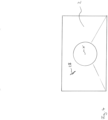
- the viewing direction of the lens 18 is directed forward in the direction of the longitudinal axis x, so that the camera 12 essentially captures an image as shown schematically in Fig. 4 is shown.
- Fig. 2 which shows a schematic top view of the front of the camera 12, the lens 18 is surrounded by several lighting devices 20, which can preferably also be controlled by the control device 10.
- a machining tool in the form of a milling cutter 22 is shown schematically on the carriage or the inspection unit 4, which can be extendable in the radial direction with respect to the longitudinal axis x.
- Structures on and in the wall of the sewer pipe 2 can be recognized in the image or video image recorded by the camera 12.
- the gap 24 of the connection point or sleeve between two pipe sections, a branch 26 and a damaged area 28 in the form of a crack are shown schematically.
- the control device 10 has an image evaluation device 30, which displays the image captured by the camera 18, as exemplified in Fig. 4 is shown, evaluated automatically.
- the image evaluation device 30 has a structure recognition module 32, which is designed to automatically recognize certain structures in the image.
- the structure recognition module 32 preferably uses an artificial intelligence, for example a neural one Network.
- Such a system can in particular be designed to be self-learning or trainable, so that it can automatically recognize certain structures. So in the captured image, as it is in Fig. 4 is shown, for example the damaged area 28 in the form of a crack can be identified by the structure recognition module 32.
- control device 10 can automatically carry out at least one action. She starts one of these, for example. B. based on a recognition signal emitted by the structure recognition module 32, which signals the recognition of a specific structure.
- control device 10 can use additional measuring systems or directly from the recorded image to detect the distance a of the detected damaged area 28 from the inspection unit 4 and then advance the inspection unit 4 by the distance a in the sewer pipe 2, as in Fig. 3 is shown.
- the inspection unit 4 is in the advanced position.
- the control device 10 is not shown again. It should be understood that this is trained in the same way as in Fig. 1 shown.
- the control device 10 controls a swivel drive of the camera 12 in such a way that the lens 18 is directed frontally towards the detected damaged area 28 in the radial direction to the longitudinal axis x, so that this can now be viewed in detail on the monitor 14.
- control device 10 This approach and positioning process can be initiated fully automatically by the control device 10, so that an operator then only has to look closely at the damaged area 28.
- the camera 12 could also be equipped with a zoom in order to be able to take a closer look at a damaged area.
- control device 10 could also control the lighting devices 20 to change the lighting for closer inspection.
- control device 10 could automatically control the processing tool 22 in order to automatically initiate a processing process, for example milling the junction of the branch 26, preferably under observation of the camera 12.
- the camera 12 could be equipped with a feed drive 34, which makes it possible to advance the camera 12 into the branch 26 after the inspection unit 4 has been positioned accordingly. This can also be done automatically if the structure recognition module 32 has recognized the branch 26. That is, the inspection unit 4 is positioned accordingly by the control device 10 and the camera 12 is automatically moved into the branch 26.
- the control device 10 can initiate any desired actions, which can basically include all functionalities of an inspection device, for example rinsing, adjusting a detergent supply, a measurement, data storage, etc.
- the measurement could, for example, be a height measurement using a position and/or location sensor 36 in the inspection unit 4. For example, after a damaged area 38 has been detected, its position or situation could be recorded and documented.
- the structure recognition module 32 can be designed as an autonomous system with the control device 10. However, it is also possible for the control device 10 to communicate with a central computing system 40 via a communication connection 38, as shown schematically in Fig. 1 is shown.
- the structure recognition module 32 could be completely or partially outsourced to a central computing system 40, whereby Image data recorded by the control device 10 would then be transmitted to the central computing system 40 via the communication interface 38. Alternatively or additionally, it is possible to train the structure recognition module 32 via the central computing system 40 or to supply it with basic data for structure recognition.
- the structure recognition module 32 can transmit its recorded or recognized structure data to the central computing system 40, so that basic data can be updated in this, which in turn can be made available to the structure recognition module 32 and preferably further structure recognition modules 32 via corresponding communication connections 38.
- the central computing system 40 can be connected via the Internet, so that in this way many cavity inspection systems with many structure recognition modules 32 can learn from each other and be updated together.
- control device 10 into the camera 12 or the inspection unit 4, so that it could be designed as an autonomously driving camera or an autonomously driving and working robot or sewer robot.
Landscapes
- Engineering & Computer Science (AREA)
- Physics & Mathematics (AREA)
- General Physics & Mathematics (AREA)
- Remote Sensing (AREA)
- Radar, Positioning & Navigation (AREA)
- Electromagnetism (AREA)
- Multimedia (AREA)
- Health & Medical Sciences (AREA)
- Life Sciences & Earth Sciences (AREA)
- Hydrology & Water Resources (AREA)
- Public Health (AREA)
- Water Supply & Treatment (AREA)
- Computer Vision & Pattern Recognition (AREA)
- Theoretical Computer Science (AREA)
- Investigating Materials By The Use Of Optical Means Adapted For Particular Applications (AREA)
Applications Claiming Priority (1)
| Application Number | Priority Date | Filing Date | Title |
|---|---|---|---|
| DE102018212216.4A DE102018212216A1 (de) | 2018-07-23 | 2018-07-23 | Hohlrauminspektionssystem |
Publications (3)
| Publication Number | Publication Date |
|---|---|
| EP3599510A1 EP3599510A1 (de) | 2020-01-29 |
| EP3599510C0 EP3599510C0 (de) | 2024-03-06 |
| EP3599510B1 true EP3599510B1 (de) | 2024-03-06 |
Family
ID=67438405
Family Applications (1)
| Application Number | Title | Priority Date | Filing Date |
|---|---|---|---|
| EP19187622.6A Active EP3599510B1 (de) | 2018-07-23 | 2019-07-22 | Hohlrauminspektionssystem |
Country Status (4)
| Country | Link |
|---|---|
| EP (1) | EP3599510B1 (pl) |
| DE (1) | DE102018212216A1 (pl) |
| ES (1) | ES2978503T3 (pl) |
| PL (1) | PL3599510T3 (pl) |
Families Citing this family (6)
| Publication number | Priority date | Publication date | Assignee | Title |
|---|---|---|---|---|
| DE102018212216A1 (de) | 2018-07-23 | 2020-01-23 | Ibak Helmut Hunger Gmbh & Co. Kg | Hohlrauminspektionssystem |
| DE102022205182B4 (de) * | 2022-05-24 | 2024-06-27 | Ibak Helmut Hunger Gmbh & Co Kg | Verfahren zur Steuerung einer Kamera eines Kanalrohrinspektionsgerätes sowie Kanalrohrinspektionsgerät mit angeordneter Kamera |
| DE102022205181A1 (de) | 2022-05-24 | 2023-11-30 | Ibak Helmut Hunger Gmbh & Co Kg | Kanalrohrinspektionssystem sowie Verfahren zur Steuerung eines Kanalrohrinspektionssystems |
| DE102023112061A1 (de) | 2023-05-09 | 2024-11-14 | Ipek International Gmbh | System und Verfahren zum Steuern einer Kamera eines Kanalinspektions- und/oder Wartungssystems |
| DE102023206685A1 (de) * | 2023-07-13 | 2025-01-16 | Ibak Helmut Hunger Gmbh & Co Kg | Kanalbearbeitungsvorrichtung |
| DE102023125686B4 (de) * | 2023-09-21 | 2025-07-10 | Ibak Helmut Hunger Gmbh & Co Kg | Hohlrauminspektionsvorrichtung und Verfahren zur Steuerung der Beleuchtung einer Hohlrauminspektionsvorrichtung |
Citations (11)
| Publication number | Priority date | Publication date | Assignee | Title |
|---|---|---|---|---|
| US20030023404A1 (en) | 2000-11-22 | 2003-01-30 | Osama Moselhi | Method and apparatus for the automated detection and classification of defects in sewer pipes |
| WO2006000271A1 (de) | 2004-06-23 | 2006-01-05 | Rico Gesellschaft Für Mikroelektronik | Verfahren zur steuerung einer rohrrevisionsanlage und zur auswertung der revisionsdaten |
| EP1639337A1 (de) | 2003-06-25 | 2006-03-29 | RICO GESELLSCHAFT FüR MIKROELEKTRONIK mbH | Kamerawagen |
| US20060290779A1 (en) | 2005-01-18 | 2006-12-28 | Reverte Carlos F | Autonomous inspector mobile platform |
| DE102010044465A1 (de) * | 2010-09-06 | 2012-03-08 | I.S.T. Innovative Sewer Technologies Gmbh | Vorrichtung zum Sanieren eines Rohres |
| DE202013100437U1 (de) | 2013-01-30 | 2013-02-06 | Ipek International Gmbh | Vorrichtung zur Abstandsmessung in Rohrleitungen |
| DE102013211795A1 (de) | 2013-06-21 | 2014-06-05 | Ibak Helmut Hunger Gmbh & Co. Kg | Detektorvorrichtung zum Erkennen von verborgenen Strukturen in Wandungen |
| EP3107047A1 (de) | 2015-06-15 | 2016-12-21 | iPEK International GmbH | System und verfahren zur ortung und darstellung von inspektionsdaten |
| US20170323163A1 (en) | 2016-05-06 | 2017-11-09 | City Of Long Beach | Sewer pipe inspection and diagnostic system and method |
| CN108038850A (zh) | 2017-12-08 | 2018-05-15 | 天津大学 | 一种基于深度学习的排水管道异常类型自动检测方法 |
| EP3599510A1 (de) | 2018-07-23 | 2020-01-29 | IBAK Helmut Hunger GmbH & Co. KG | Hohlrauminspektionssystem |
Family Cites Families (2)
| Publication number | Priority date | Publication date | Assignee | Title |
|---|---|---|---|---|
| DE9209821U1 (de) * | 1992-07-22 | 1993-11-11 | JT Elektronik GmbH, 88131 Lindau | Fräs- und Schleif-Einheit zum Abfräsen von in Rohren hineinreagende Abflußhindernisse |
| DE20308761U1 (de) * | 2003-06-05 | 2004-10-14 | Jt-Elektronik Gmbh | Kanalfahrwagen zur Untersuchung von Kanalrohren |
-
2018
- 2018-07-23 DE DE102018212216.4A patent/DE102018212216A1/de active Pending
-
2019
- 2019-07-22 EP EP19187622.6A patent/EP3599510B1/de active Active
- 2019-07-22 ES ES19187622T patent/ES2978503T3/es active Active
- 2019-07-22 PL PL19187622.6T patent/PL3599510T3/pl unknown
Patent Citations (12)
| Publication number | Priority date | Publication date | Assignee | Title |
|---|---|---|---|---|
| US20030023404A1 (en) | 2000-11-22 | 2003-01-30 | Osama Moselhi | Method and apparatus for the automated detection and classification of defects in sewer pipes |
| EP1639337A1 (de) | 2003-06-25 | 2006-03-29 | RICO GESELLSCHAFT FüR MIKROELEKTRONIK mbH | Kamerawagen |
| WO2006000271A1 (de) | 2004-06-23 | 2006-01-05 | Rico Gesellschaft Für Mikroelektronik | Verfahren zur steuerung einer rohrrevisionsanlage und zur auswertung der revisionsdaten |
| US20080021662A1 (en) | 2004-06-23 | 2008-01-24 | Hinn Albert K | Method For Controlling A Pipe Inspection System And For Evaluating The Inspection Data |
| US20060290779A1 (en) | 2005-01-18 | 2006-12-28 | Reverte Carlos F | Autonomous inspector mobile platform |
| DE102010044465A1 (de) * | 2010-09-06 | 2012-03-08 | I.S.T. Innovative Sewer Technologies Gmbh | Vorrichtung zum Sanieren eines Rohres |
| DE202013100437U1 (de) | 2013-01-30 | 2013-02-06 | Ipek International Gmbh | Vorrichtung zur Abstandsmessung in Rohrleitungen |
| DE102013211795A1 (de) | 2013-06-21 | 2014-06-05 | Ibak Helmut Hunger Gmbh & Co. Kg | Detektorvorrichtung zum Erkennen von verborgenen Strukturen in Wandungen |
| EP3107047A1 (de) | 2015-06-15 | 2016-12-21 | iPEK International GmbH | System und verfahren zur ortung und darstellung von inspektionsdaten |
| US20170323163A1 (en) | 2016-05-06 | 2017-11-09 | City Of Long Beach | Sewer pipe inspection and diagnostic system and method |
| CN108038850A (zh) | 2017-12-08 | 2018-05-15 | 天津大学 | 一种基于深度学习的排水管道异常类型自动检测方法 |
| EP3599510A1 (de) | 2018-07-23 | 2020-01-29 | IBAK Helmut Hunger GmbH & Co. KG | Hohlrauminspektionssystem |
Non-Patent Citations (31)
| Title |
|---|
| "Thesis", 1 July 2015, CONCORDIA UNIVERSITY, Montreal, Quebec, Canada, article DAHER SAMI: "Defect-based Condition Assessment Model and Protocol of Sewer Pipelines", pages: 1 - 215, XP093245810 |
| AHRARY A., ISHIKAWA M.: "Self-Localization of Autonomous Sewer Robots by Using a Stereo Camera and a Laser Scanner", NETWORKING, SENSING AND CONTROL, 2006. ICNSC '06. PROCEEDINGS OF THE 2 006 IEEE INTERNATIONAL CONFERENCE ON FT. LAUDERDALE, FL, USA 23-25 APRIL 2006, PISCATAWAY, NJ, USA,IEEE, 23 April 2006 (2006-04-23) - 25 April 2006 (2006-04-25), pages 78 - 83, XP010934561, ISBN: 978-1-4244-0065-2, DOI: 10.1109/ICNSC.2006.1673121 |
| AHRARY A., LI TIAN, KAMATA S., ISHIKAWA M.: "An Autonomous Sewer Robots Navigation Based on Stereo Camera Information", TOOLS WITH ARTIFICIAL INTELLIGENCE, 2005. ICTAI 05. 17TH IEEE INTERNAT IONAL CONFERENCE ON HONG KONG, CHINA 14-16 NOV. 2005, PISCATAWAY, NJ, USA,IEEE, 14 November 2005 (2005-11-14) - 16 November 2005 (2005-11-16), pages 628 - 633, XP010868038, ISBN: 978-0-7695-2488-7, DOI: 10.1109/ICTAI.2005.35 |
| ANONYMOUS: "Arbeitshilfen Abwasser: Planung, Bau und Betrieb von abwassertechnischen Anlagen in Liegenschaften des Bundes", ARBEITSHILFEN ABWASSER, BUNDESMINISTERIUM DER VERTEIDIGUNG BUNDESMINISTERIUM FÜR VERKEHR, BAU UND STADTENTWICKLUNG, pages 1 - 1110, XP093245768, Retrieved from the Internet <URL:https://www.bfr-abwasser.de/html/Materialien.1.04.html> |
| ANONYMOUS: "BMBF-Projekt AUZUKA auf der IFAT vorgestellt", 3R, 2 July 2018 (2018-07-02), pages 1 - 4, XP055723814, Retrieved from the Internet <URL:https://www.3r-rohre.de/aktuell/aus-der-praxis/02-07-2018-bmbf-projekt-auzuka-auf-der-ifat-vorgestellt/> [retrieved on 20200819] * |
| ANONYMOUS: "BMBF-Projekt AUZUKA auf der IFAT vorgestellt", 3R, pages 1 - 4, XP055723814, Retrieved from the Internet <URL:https://www.3r-rohre.de/aktuell/aus-der-praxis/02-07-2018-bmbf-projekt-auzuka-auf-der-ifat-vorgestellt/> [retrieved on 20200819] |
| ANONYMOUS: "Machine learning", WIKIPEDIA, pages 1 - 4, XP093245776, Retrieved from the Internet <URL:https://en.wikipedia.org/w/index.php?title=Machine_learning&oldid=249711943> |
| ANONYMOUS: "Mustererkennung", WIKIPEDIA, pages 1 - 6, XP093245772, Retrieved from the Internet <URL:https://de.wikipedia.org/w/index.php?title=Mustererkennung&oldid=173731192> |
| ANONYMOUS: "Pattern recognition", WIKIPEDIA, pages 1 - 3, XP093245774, Retrieved from the Internet <URL:https://en.wikipedia.org/w/index.php?title=Pattern_recognition&oldid=250253139> |
| D36 - Merkmalsgliederung des Patentanspruches 1 |
| D37 - Streitpatent in der ursprünglich Fassung |
| DURAN O., ALTHOEFER K., SENEVIRATNE L.D.: "Automated sewer inspection using image processing and a neural classifier", PROCEEDINGS OF THE 2002 INTERNATIONAL JOINT CONFERENCE ON NEURAL NETWORKS. IJCNN'02. HONOLULU, HAWAII, MAY 12 - 17, 2002., NEW YORK, NY : IEEE., US, 7 August 2002 (2002-08-07) - 17 May 2002 (2002-05-17), US , pages 1126 - 1131, XP093245782, ISBN: 978-0-7803-7278-8, DOI: 10.1109/IJCNN.2002.1007652 |
| GAJANAN K. CHOUDHARY ; SAYAN DEY: "Crack detection in concrete surfaces using image processing, fuzzy logic, and neural networks", ADVANCED COMPUTATIONAL INTELLIGENCE (ICACI), 2012 IEEE FIFTH INTERNATIONAL CONFERENCE ON, IEEE, 18 October 2012 (2012-10-18), pages 404 - 411, XP032331224, ISBN: 978-1-4673-1743-6, DOI: 10.1109/ICACI.2012.6463195 |
| GOOCH R.M., CLARKE T.A., ELLIS T.J.: "A semi-autonomous sewer surveillance and inspection vehicle", INTELLIGENT VEHICLES SYMPOSIUM, 1996., PROCEEDINGS OF THE 1996 IEEE TOKYO, JAPAN 19-20 SEPT. 1996, NEW YORK, NY, USA,IEEE, US, 19 September 1996 (1996-09-19) - 20 September 1996 (1996-09-20), US , pages 64 - 69, XP010209711, ISBN: 978-0-7803-3652-0, DOI: 10.1109/IVS.1996.566354 |
| GUO, W. ; SOIBELMAN, L. ; GARRETT, J.H.: "Automated defect detection for sewer pipeline inspection and condition assessment", AUTOMATION IN CONSTRUCTION, ELSEVIER, AMSTERDAM, NL, vol. 18, no. 5, 1 August 2009 (2009-08-01), AMSTERDAM, NL , pages 587 - 596, XP026826175, ISSN: 0926-5805, DOI: 10.1016/j.autcon.2008.12.003 |
| HERTZBERG J., KIRCHNER F.: "Landmark-based autonomous navigation in sewerage pipes", ADVANCED MOBILE ROBOT, 1996., PROCEEDINGS OF THE FIRST EUROMICRO WORKS HOP ON KAISERSLAUTERN, GERMANY 9-11 OCT. 1996, LOS ALAMITOS, CA, USA,IEEE COMPUT. SOC., US, 9 October 1996 (1996-10-09) - 11 October 1996 (1996-10-11), US , pages 68 - 73, XP010198353, ISBN: 978-0-8186-7695-6, DOI: 10.1109/EURBOT.1996.551883 |
| JAN WASCHNEWSKI: "Automatische Zustandsanalyse von Abwasserkanälen durch virtuelle Begehung; Vorstellung des BMBF-Projektes AUZUKA", - 13 July 2017 (2017-07-13), pages 1 - 14, XP055723803, Retrieved from the Internet <URL:https://web.archive.org/web/20210414234019/https://www.kompetenz-wasser.de/wp-content/uploads/2017/08/170713_ww42_waschnewski.pdf> [retrieved on 20200819] |
| JAN WASCHNEWSKI: "Automatische Zustandsanalyse von Abwasserkan�len durch virtuelle Begehung - Vorstellung des BMBF-Projektes AUZUKA -", 18 July 2017 (2017-07-18), pages 1 - 14, XP055723803, Retrieved from the Internet <URL:https://www.kompetenz-wasser.de/wp-content/uploads/2017/08/170713_ww42_waschnewski.pdf> [retrieved on 20200819] * |
| JT-ELEKTRONIK: "AUZUKA - Ein BMBF-Projekt mit sehr interessantem Messeauftritt", KANALINSPEKTEURE.DE, 26 June 2018 (2018-06-26), pages 1 - 4, XP055723812, Retrieved from the Internet <URL:https://www.kanalinspekteure.de/index.php?/technik.html/records/auzuka-ein-bmbf-projekt-mit-sehr-interessantem-messeauftritt-r30/> [retrieved on 20200819] * |
| JT-ELEKTRONIK: "AUZUKA - Ein BMBF-Projekt mit sehr interessantem Messeauftritt", KANALINSPEKTEURE.DE, pages 1 - 4, XP055723812, Retrieved from the Internet <URL:https://www.kanalinspekteure.de/index.php?/technik.html/records/auzuka-ein-bmbf-projekt-mit-sehr-interessantem-messeauftritt-r30/> [retrieved on 20200819] |
| KIRCHNER F., HERTZBERG J.: "A PROTOTYPE STUDY OF AN AUTONOMOUS ROBOT PLATFORM FOR SEWERAGE SYSTEM MAINTENANCE.", AUTONOMOUS ROBOTS, KLUWER ACADEMIC PUBLISHERS, DORDRECHT., NL, vol. 04., no. 04., 1 October 1997 (1997-10-01), NL , pages 319 - 331., XP000727674, ISSN: 0929-5593, DOI: 10.1023/A:1008896121662 |
| KLAUS-PETER BÖLKE: "Kanalinspektion: „Zustände erkennen und dokumentieren", 4. Auflage", 20 December 2013, SPRINGER VIEWEG, ISBN: 978-3-642-39220-7, article KLAUS-PETER BÖLKE: "11.1.1 Haltungsprotokolle", pages: 378 - 383, XP009559257, DOI: 10.1007/978-3-642-39221-4_11 |
| KLAUS-PETER BÖLKE: "Kanalinspektion: „Zustände erkennen und dokumentieren", 4. Auflage", 20 December 2013, SPRINGER VIEWEG, ISBN: 978-3-642-39220-7, article KLAUS-PETER BÖLKE: "12. Messverfahren", pages: 395 - 420, XP009559258, DOI: 10.1007/978-3-642-39221-4_12 |
| KLAUS-PETER BÖLKE: "Kanalinspektion: „Zustände erkennen und dokumentieren", 4. Auflage", 20 December 2013, SPRINGER VIEWEG, ISBN: 978-3-642-39220-7, article KLAUS-PETER BÖLKE: "5.6.2 Positionierung", pages: 121 - 122, XP009559256, DOI: 10.1007/978-3-642-39221-4_5 |
| MOHAMMED SAMIA, HALIM EMERA ABDEL, NOUR MOHAMMED, DEAN EL, NAGUIB ESMAIL M F, GALAL-EDEEN GALAL HASSAN: "Intelligent Framework for the Combining between GIS, Data Mining & Decision Support System", CONTEMPORARY ENGINEERING SCIENCES, HIKARI LTD., vol. 5, no. 12, 1 December 2012 (2012-12-01), pages 531 - 562, XP093245818, ISSN: 1313-6569, DOI: 10.12988/ces |
| MOSELHI, O. SHEHAB-ELDEEN, T.: "Automated detection of surface defects in water and sewer pipes", AUTOMATION IN CONSTRUCTION, ELSEVIER, AMSTERDAM, NL, vol. 8, no. 5, 1 June 1999 (1999-06-01), AMSTERDAM, NL , pages 581 - 588, XP004169978, ISSN: 0926-5805, DOI: 10.1016/S0926-5805(99)00007-2 |
| OSAMA MOSELHI, TARIQ SHEHAB-ELDEEN: "Classification of Defects in Sewer Pipes Using Neural Networks", JOURNAL OF INFRASTRUCTURE SYSTEMS, AMERICAN SOCIETY OF CIVIL ENGINEERS, NEW YORK, vol. 6, no. 3, 1 September 2000 (2000-09-01), New York , pages 97 - 104, XP009559259, ISSN: 1076-0342, DOI: 10.1061/(ASCE)1076-0342(2000)6:3(97) |
| THOMAS WERNER ET AL: "Projekt AUZUKA", JT-ELEKTRONIK NEWSLETTER 10/2018, 1 October 2018 (2018-10-01), XP055753658 * |
| THOMAS WERNER, WASCHNEWSKI JAN: "Projekt AUZUKA", JT-ELEKTRONIK NEWSLETTER 10/2018, JT-ELEKTRONIK GMBH, 1 October 2018 (2018-10-01), XP055753658 |
| THOMAS WERNER: "Roboter, Rost und Rohrbruch Robotik und neuronale Netze sichern kritische Infrastrukturen", INNOVISIONS, 31 March 2017 (2017-03-31), pages 1 - 2, XP055723808, Retrieved from the Internet <URL:https://www.fraunhofer-innovisions.de/maschinelles-lernen/roboter-rost-und-rohrbruch/> [retrieved on 20200819] * |
| THOMAS WERNER: "Roboter, Rost und Rohrbruch Robotik und neuronale Netze sichern kritische Infrastrukturen", INNOVISIONS, pages 1 - 2, XP055723808, Retrieved from the Internet <URL:https://www.fraunhofer-innovisions.de/maschinelles-lernen/roboter-rost-und-rohrbruch/> [retrieved on 20200819] |
Also Published As
| Publication number | Publication date |
|---|---|
| ES2978503T3 (es) | 2024-09-13 |
| DE102018212216A1 (de) | 2020-01-23 |
| EP3599510C0 (de) | 2024-03-06 |
| PL3599510T3 (pl) | 2024-07-15 |
| EP3599510A1 (de) | 2020-01-29 |
Similar Documents
| Publication | Publication Date | Title |
|---|---|---|
| EP3599510B1 (de) | Hohlrauminspektionssystem | |
| EP2975455B1 (de) | Fokussiersystem sowie kameraeinheit mit einem fokussiersystem | |
| EP1761759B1 (de) | Verfahren zur steuerung einer rohrrevisionsanlage und zur auswertung der revisionsdaten | |
| EP2423101B1 (de) | Unbemanntes Unterwasserfahrzeug und Verfahren zum Betrieb eines unbemannten Unterwasserfahrzeugs | |
| EP3912127B1 (de) | Verfahren und vorrichtung zur inspektion schwer erreichbarer komponenten | |
| DE202012100128U1 (de) | Erfassungssystem zur Informationsgewinnung in rohrartigen Elementen | |
| DE102014118457B4 (de) | System und Verfahren zum Steuern von Inspektions- und/oder Wartungseinheiten | |
| EP2886239A1 (de) | Verfahren und Vorrichtung zur Überwachung und Regelung der Bearbeitungsbahn bei einem Laser-Fügeprozess | |
| DE102013010010B4 (de) | Verfahren zum Betrieb eines Fahrerassistenzsystems zum Rangieren und/oder Parken | |
| EP3950159A1 (de) | Reinigungssystem, computerprogramm und datenträgersignal | |
| EP1266099B1 (de) | Verfahren zum wiederauffinden von vorgebbaren stellen in kanal- und rohrleitungssystemen | |
| DE202015006362U1 (de) | Reinigungseinrichtung zum Reinigen von Kanälen | |
| EP3416401B1 (de) | Mobiles transportmittel zum transportieren von datensammlern, datensammelsystem und datensammelverfahren | |
| DE102021110287A1 (de) | Verfahren und System zum automatisierten Kalibrieren von Sensoren | |
| DE202021003909U1 (de) | Rohr- und Kanalinspektionsvorrichtung | |
| EP4206814B1 (de) | Rohr- und kanalinspektionsvorrichtung | |
| DE102015119806A1 (de) | Verfahren zur Darstellung der Bearbeitung in einer Werkzeugmaschine | |
| DE102012112411B3 (de) | Pressbohrlenkvorrichtung | |
| DE102017123195A1 (de) | System und Verfahren zum Navigieren eines Flugzeugs in einer Halle | |
| DE102018210361B4 (de) | Verfahren zum Ermitteln einer Relativpose zwischen einem Fahrzeug und einem Zielobjekt | |
| DE112023005444T5 (de) | Inspektionswerkzeug mit Computervision | |
| EP4284012A1 (de) | Verfahren zur steuerung einer kamera eines kanalrohrinspektionsgerätes | |
| DE102023125686B4 (de) | Hohlrauminspektionsvorrichtung und Verfahren zur Steuerung der Beleuchtung einer Hohlrauminspektionsvorrichtung | |
| DE102017006180A1 (de) | Verfahren zum Betrieb eines Fahrzeugs | |
| WO2025051348A1 (de) | Ermittlung der räumlichen lage von zielobjekten für autonome roboter |
Legal Events
| Date | Code | Title | Description |
|---|---|---|---|
| PUAI | Public reference made under article 153(3) epc to a published international application that has entered the european phase |
Free format text: ORIGINAL CODE: 0009012 |
|
| STAA | Information on the status of an ep patent application or granted ep patent |
Free format text: STATUS: THE APPLICATION HAS BEEN PUBLISHED |
|
| AK | Designated contracting states |
Kind code of ref document: A1 Designated state(s): AL AT BE BG CH CY CZ DE DK EE ES FI FR GB GR HR HU IE IS IT LI LT LU LV MC MK MT NL NO PL PT RO RS SE SI SK SM TR |
|
| AX | Request for extension of the european patent |
Extension state: BA ME |
|
| STAA | Information on the status of an ep patent application or granted ep patent |
Free format text: STATUS: REQUEST FOR EXAMINATION WAS MADE |
|
| TPAC | Observations filed by third parties |
Free format text: ORIGINAL CODE: EPIDOSNTIPA |
|
| 17P | Request for examination filed |
Effective date: 20200703 |
|
| RBV | Designated contracting states (corrected) |
Designated state(s): AL AT BE BG CH CY CZ DE DK EE ES FI FR GB GR HR HU IE IS IT LI LT LU LV MC MK MT NL NO PL PT RO RS SE SI SK SM TR |
|
| STAA | Information on the status of an ep patent application or granted ep patent |
Free format text: STATUS: EXAMINATION IS IN PROGRESS |
|
| 17Q | First examination report despatched |
Effective date: 20210111 |
|
| REG | Reference to a national code |
Ref country code: DE Ref legal event code: R079 Ref country code: DE Ref legal event code: R079 Ref document number: 502019010719 Country of ref document: DE Free format text: PREVIOUS MAIN CLASS: G03B0037000000 Ipc: F16L0055280000 |
|
| GRAP | Despatch of communication of intention to grant a patent |
Free format text: ORIGINAL CODE: EPIDOSNIGR1 |
|
| STAA | Information on the status of an ep patent application or granted ep patent |
Free format text: STATUS: GRANT OF PATENT IS INTENDED |
|
| RIC1 | Information provided on ipc code assigned before grant |
Ipc: G03B 37/00 20060101ALI20231129BHEP Ipc: G01N 21/954 20060101ALI20231129BHEP Ipc: G01C 7/06 20060101ALI20231129BHEP Ipc: F16L 55/28 20060101AFI20231129BHEP |
|
| INTG | Intention to grant announced |
Effective date: 20231215 |
|
| GRAS | Grant fee paid |
Free format text: ORIGINAL CODE: EPIDOSNIGR3 |
|
| GRAA | (expected) grant |
Free format text: ORIGINAL CODE: 0009210 |
|
| STAA | Information on the status of an ep patent application or granted ep patent |
Free format text: STATUS: THE PATENT HAS BEEN GRANTED |
|
| AK | Designated contracting states |
Kind code of ref document: B1 Designated state(s): AL AT BE BG CH CY CZ DE DK EE ES FI FR GB GR HR HU IE IS IT LI LT LU LV MC MK MT NL NO PL PT RO RS SE SI SK SM TR |
|
| REG | Reference to a national code |
Ref country code: CH Ref legal event code: EP |
|
| REG | Reference to a national code |
Ref country code: DE Ref legal event code: R096 Ref document number: 502019010719 Country of ref document: DE |
|
| REG | Reference to a national code |
Ref country code: IE Ref legal event code: FG4D Free format text: LANGUAGE OF EP DOCUMENT: GERMAN |
|
| U01 | Request for unitary effect filed |
Effective date: 20240306 |
|
| U07 | Unitary effect registered |
Designated state(s): AT BE BG DE DK EE FI FR IT LT LU LV MT NL PT SE SI Effective date: 20240313 |
|
| PG25 | Lapsed in a contracting state [announced via postgrant information from national office to epo] |
Ref country code: GR Free format text: LAPSE BECAUSE OF FAILURE TO SUBMIT A TRANSLATION OF THE DESCRIPTION OR TO PAY THE FEE WITHIN THE PRESCRIBED TIME-LIMIT Effective date: 20240607 |
|
| PG25 | Lapsed in a contracting state [announced via postgrant information from national office to epo] |
Ref country code: RS Free format text: LAPSE BECAUSE OF FAILURE TO SUBMIT A TRANSLATION OF THE DESCRIPTION OR TO PAY THE FEE WITHIN THE PRESCRIBED TIME-LIMIT Effective date: 20240606 Ref country code: HR Free format text: LAPSE BECAUSE OF FAILURE TO SUBMIT A TRANSLATION OF THE DESCRIPTION OR TO PAY THE FEE WITHIN THE PRESCRIBED TIME-LIMIT Effective date: 20240306 |
|
| PG25 | Lapsed in a contracting state [announced via postgrant information from national office to epo] |
Ref country code: RS Free format text: LAPSE BECAUSE OF FAILURE TO SUBMIT A TRANSLATION OF THE DESCRIPTION OR TO PAY THE FEE WITHIN THE PRESCRIBED TIME-LIMIT Effective date: 20240606 Ref country code: NO Free format text: LAPSE BECAUSE OF FAILURE TO SUBMIT A TRANSLATION OF THE DESCRIPTION OR TO PAY THE FEE WITHIN THE PRESCRIBED TIME-LIMIT Effective date: 20240606 Ref country code: HR Free format text: LAPSE BECAUSE OF FAILURE TO SUBMIT A TRANSLATION OF THE DESCRIPTION OR TO PAY THE FEE WITHIN THE PRESCRIBED TIME-LIMIT Effective date: 20240306 Ref country code: GR Free format text: LAPSE BECAUSE OF FAILURE TO SUBMIT A TRANSLATION OF THE DESCRIPTION OR TO PAY THE FEE WITHIN THE PRESCRIBED TIME-LIMIT Effective date: 20240607 |
|
| U20 | Renewal fee for the european patent with unitary effect paid |
Year of fee payment: 6 Effective date: 20240703 |
|
| REG | Reference to a national code |
Ref country code: ES Ref legal event code: FG2A Ref document number: 2978503 Country of ref document: ES Kind code of ref document: T3 Effective date: 20240913 |
|
| PG25 | Lapsed in a contracting state [announced via postgrant information from national office to epo] |
Ref country code: IS Free format text: LAPSE BECAUSE OF FAILURE TO SUBMIT A TRANSLATION OF THE DESCRIPTION OR TO PAY THE FEE WITHIN THE PRESCRIBED TIME-LIMIT Effective date: 20240706 |
|
| PG25 | Lapsed in a contracting state [announced via postgrant information from national office to epo] |
Ref country code: SM Free format text: LAPSE BECAUSE OF FAILURE TO SUBMIT A TRANSLATION OF THE DESCRIPTION OR TO PAY THE FEE WITHIN THE PRESCRIBED TIME-LIMIT Effective date: 20240306 |
|
| PG25 | Lapsed in a contracting state [announced via postgrant information from national office to epo] |
Ref country code: CZ Free format text: LAPSE BECAUSE OF FAILURE TO SUBMIT A TRANSLATION OF THE DESCRIPTION OR TO PAY THE FEE WITHIN THE PRESCRIBED TIME-LIMIT Effective date: 20240306 |
|
| PG25 | Lapsed in a contracting state [announced via postgrant information from national office to epo] |
Ref country code: SK Free format text: LAPSE BECAUSE OF FAILURE TO SUBMIT A TRANSLATION OF THE DESCRIPTION OR TO PAY THE FEE WITHIN THE PRESCRIBED TIME-LIMIT Effective date: 20240306 |
|
| PG25 | Lapsed in a contracting state [announced via postgrant information from national office to epo] |
Ref country code: SM Free format text: LAPSE BECAUSE OF FAILURE TO SUBMIT A TRANSLATION OF THE DESCRIPTION OR TO PAY THE FEE WITHIN THE PRESCRIBED TIME-LIMIT Effective date: 20240306 Ref country code: SK Free format text: LAPSE BECAUSE OF FAILURE TO SUBMIT A TRANSLATION OF THE DESCRIPTION OR TO PAY THE FEE WITHIN THE PRESCRIBED TIME-LIMIT Effective date: 20240306 Ref country code: RO Free format text: LAPSE BECAUSE OF FAILURE TO SUBMIT A TRANSLATION OF THE DESCRIPTION OR TO PAY THE FEE WITHIN THE PRESCRIBED TIME-LIMIT Effective date: 20240306 Ref country code: IS Free format text: LAPSE BECAUSE OF FAILURE TO SUBMIT A TRANSLATION OF THE DESCRIPTION OR TO PAY THE FEE WITHIN THE PRESCRIBED TIME-LIMIT Effective date: 20240706 Ref country code: CZ Free format text: LAPSE BECAUSE OF FAILURE TO SUBMIT A TRANSLATION OF THE DESCRIPTION OR TO PAY THE FEE WITHIN THE PRESCRIBED TIME-LIMIT Effective date: 20240306 |
|
| REG | Reference to a national code |
Ref country code: DE Ref legal event code: R026 Ref document number: 502019010719 Country of ref document: DE |
|
| PLBI | Opposition filed |
Free format text: ORIGINAL CODE: 0009260 |
|
| PLAX | Notice of opposition and request to file observation + time limit sent |
Free format text: ORIGINAL CODE: EPIDOSNOBS2 |
|
| 26 | Opposition filed |
Opponent name: IPEK INTERNATIONAL GMBH Effective date: 20241205 |
|
| PG25 | Lapsed in a contracting state [announced via postgrant information from national office to epo] |
Ref country code: MC Free format text: LAPSE BECAUSE OF FAILURE TO SUBMIT A TRANSLATION OF THE DESCRIPTION OR TO PAY THE FEE WITHIN THE PRESCRIBED TIME-LIMIT Effective date: 20240306 |
|
| PLBB | Reply of patent proprietor to notice(s) of opposition received |
Free format text: ORIGINAL CODE: EPIDOSNOBS3 |
|
| PG25 | Lapsed in a contracting state [announced via postgrant information from national office to epo] |
Ref country code: IE Free format text: LAPSE BECAUSE OF NON-PAYMENT OF DUE FEES Effective date: 20240722 |
|
| U20 | Renewal fee for the european patent with unitary effect paid |
Year of fee payment: 7 Effective date: 20250709 |
|
| PGFP | Annual fee paid to national office [announced via postgrant information from national office to epo] |
Ref country code: ES Payment date: 20250819 Year of fee payment: 7 |
|
| PGFP | Annual fee paid to national office [announced via postgrant information from national office to epo] |
Ref country code: PL Payment date: 20250710 Year of fee payment: 7 |
|
| PGFP | Annual fee paid to national office [announced via postgrant information from national office to epo] |
Ref country code: GB Payment date: 20250724 Year of fee payment: 7 |
|
| PGFP | Annual fee paid to national office [announced via postgrant information from national office to epo] |
Ref country code: CH Payment date: 20250801 Year of fee payment: 7 |