EP3599501A1 - Heat-absorbing modulator-switch with two stacked rings - Google Patents
Heat-absorbing modulator-switch with two stacked rings Download PDFInfo
- Publication number
- EP3599501A1 EP3599501A1 EP19186973.4A EP19186973A EP3599501A1 EP 3599501 A1 EP3599501 A1 EP 3599501A1 EP 19186973 A EP19186973 A EP 19186973A EP 3599501 A1 EP3599501 A1 EP 3599501A1
- Authority
- EP
- European Patent Office
- Prior art keywords
- ring
- waveguide
- optical
- guide
- ring waveguide
- Prior art date
- Legal status (The legal status is an assumption and is not a legal conclusion. Google has not performed a legal analysis and makes no representation as to the accuracy of the status listed.)
- Granted
Links
- 239000000463 material Substances 0.000 claims abstract description 44
- 230000003287 optical effect Effects 0.000 claims abstract description 38
- 229910052710 silicon Inorganic materials 0.000 claims description 5
- 239000010703 silicon Substances 0.000 claims description 5
- 229910052581 Si3N4 Inorganic materials 0.000 claims description 3
- HQVNEWCFYHHQES-UHFFFAOYSA-N silicon nitride Chemical compound N12[Si]34N5[Si]62N3[Si]51N64 HQVNEWCFYHHQES-UHFFFAOYSA-N 0.000 claims description 3
- XUIMIQQOPSSXEZ-UHFFFAOYSA-N Silicon Chemical compound [Si] XUIMIQQOPSSXEZ-UHFFFAOYSA-N 0.000 description 10
- 229910004298 SiO 2 Inorganic materials 0.000 description 5
- 238000009826 distribution Methods 0.000 description 5
- 238000004519 manufacturing process Methods 0.000 description 4
- 230000008542 thermal sensitivity Effects 0.000 description 4
- 230000000694 effects Effects 0.000 description 3
- 238000005253 cladding Methods 0.000 description 2
- 229920003229 poly(methyl methacrylate) Polymers 0.000 description 2
- 239000004926 polymethyl methacrylate Substances 0.000 description 2
- 230000035945 sensitivity Effects 0.000 description 2
- 238000004088 simulation Methods 0.000 description 2
- 241000287107 Passer Species 0.000 description 1
- 229910010413 TiO 2 Inorganic materials 0.000 description 1
- GWEVSGVZZGPLCZ-UHFFFAOYSA-N Titan oxide Chemical compound O=[Ti]=O GWEVSGVZZGPLCZ-UHFFFAOYSA-N 0.000 description 1
- 238000013459 approach Methods 0.000 description 1
- 239000000969 carrier Substances 0.000 description 1
- 238000004891 communication Methods 0.000 description 1
- 230000008878 coupling Effects 0.000 description 1
- 238000010168 coupling process Methods 0.000 description 1
- 238000005859 coupling reaction Methods 0.000 description 1
- 230000007547 defect Effects 0.000 description 1
- 235000021183 entrée Nutrition 0.000 description 1
- 238000005530 etching Methods 0.000 description 1
- 229910052732 germanium Inorganic materials 0.000 description 1
- GNPVGFCGXDBREM-UHFFFAOYSA-N germanium atom Chemical compound [Ge] GNPVGFCGXDBREM-UHFFFAOYSA-N 0.000 description 1
- 230000005693 optoelectronics Effects 0.000 description 1
- 239000002861 polymer material Substances 0.000 description 1
- 230000001902 propagating effect Effects 0.000 description 1
- 238000001228 spectrum Methods 0.000 description 1
- 230000006641 stabilisation Effects 0.000 description 1
- 238000011105 stabilization Methods 0.000 description 1
- OGIDPMRJRNCKJF-UHFFFAOYSA-N titanium oxide Inorganic materials [Ti]=O OGIDPMRJRNCKJF-UHFFFAOYSA-N 0.000 description 1
Images
Classifications
-
- G—PHYSICS
- G02—OPTICS
- G02F—OPTICAL DEVICES OR ARRANGEMENTS FOR THE CONTROL OF LIGHT BY MODIFICATION OF THE OPTICAL PROPERTIES OF THE MEDIA OF THE ELEMENTS INVOLVED THEREIN; NON-LINEAR OPTICS; FREQUENCY-CHANGING OF LIGHT; OPTICAL LOGIC ELEMENTS; OPTICAL ANALOGUE/DIGITAL CONVERTERS
- G02F1/00—Devices or arrangements for the control of the intensity, colour, phase, polarisation or direction of light arriving from an independent light source, e.g. switching, gating or modulating; Non-linear optics
- G02F1/01—Devices or arrangements for the control of the intensity, colour, phase, polarisation or direction of light arriving from an independent light source, e.g. switching, gating or modulating; Non-linear optics for the control of the intensity, phase, polarisation or colour
- G02F1/015—Devices or arrangements for the control of the intensity, colour, phase, polarisation or direction of light arriving from an independent light source, e.g. switching, gating or modulating; Non-linear optics for the control of the intensity, phase, polarisation or colour based on semiconductor elements with at least one potential jump barrier, e.g. PN, PIN junction
- G02F1/025—Devices or arrangements for the control of the intensity, colour, phase, polarisation or direction of light arriving from an independent light source, e.g. switching, gating or modulating; Non-linear optics for the control of the intensity, phase, polarisation or colour based on semiconductor elements with at least one potential jump barrier, e.g. PN, PIN junction in an optical waveguide structure
-
- G—PHYSICS
- G02—OPTICS
- G02F—OPTICAL DEVICES OR ARRANGEMENTS FOR THE CONTROL OF LIGHT BY MODIFICATION OF THE OPTICAL PROPERTIES OF THE MEDIA OF THE ELEMENTS INVOLVED THEREIN; NON-LINEAR OPTICS; FREQUENCY-CHANGING OF LIGHT; OPTICAL LOGIC ELEMENTS; OPTICAL ANALOGUE/DIGITAL CONVERTERS
- G02F1/00—Devices or arrangements for the control of the intensity, colour, phase, polarisation or direction of light arriving from an independent light source, e.g. switching, gating or modulating; Non-linear optics
- G02F1/01—Devices or arrangements for the control of the intensity, colour, phase, polarisation or direction of light arriving from an independent light source, e.g. switching, gating or modulating; Non-linear optics for the control of the intensity, phase, polarisation or colour
- G02F1/0121—Operation of devices; Circuit arrangements, not otherwise provided for in this subclass
-
- G—PHYSICS
- G02—OPTICS
- G02F—OPTICAL DEVICES OR ARRANGEMENTS FOR THE CONTROL OF LIGHT BY MODIFICATION OF THE OPTICAL PROPERTIES OF THE MEDIA OF THE ELEMENTS INVOLVED THEREIN; NON-LINEAR OPTICS; FREQUENCY-CHANGING OF LIGHT; OPTICAL LOGIC ELEMENTS; OPTICAL ANALOGUE/DIGITAL CONVERTERS
- G02F1/00—Devices or arrangements for the control of the intensity, colour, phase, polarisation or direction of light arriving from an independent light source, e.g. switching, gating or modulating; Non-linear optics
- G02F1/01—Devices or arrangements for the control of the intensity, colour, phase, polarisation or direction of light arriving from an independent light source, e.g. switching, gating or modulating; Non-linear optics for the control of the intensity, phase, polarisation or colour
- G02F1/015—Devices or arrangements for the control of the intensity, colour, phase, polarisation or direction of light arriving from an independent light source, e.g. switching, gating or modulating; Non-linear optics for the control of the intensity, phase, polarisation or colour based on semiconductor elements with at least one potential jump barrier, e.g. PN, PIN junction
-
- G—PHYSICS
- G02—OPTICS
- G02F—OPTICAL DEVICES OR ARRANGEMENTS FOR THE CONTROL OF LIGHT BY MODIFICATION OF THE OPTICAL PROPERTIES OF THE MEDIA OF THE ELEMENTS INVOLVED THEREIN; NON-LINEAR OPTICS; FREQUENCY-CHANGING OF LIGHT; OPTICAL LOGIC ELEMENTS; OPTICAL ANALOGUE/DIGITAL CONVERTERS
- G02F1/00—Devices or arrangements for the control of the intensity, colour, phase, polarisation or direction of light arriving from an independent light source, e.g. switching, gating or modulating; Non-linear optics
- G02F1/01—Devices or arrangements for the control of the intensity, colour, phase, polarisation or direction of light arriving from an independent light source, e.g. switching, gating or modulating; Non-linear optics for the control of the intensity, phase, polarisation or colour
- G02F1/21—Devices or arrangements for the control of the intensity, colour, phase, polarisation or direction of light arriving from an independent light source, e.g. switching, gating or modulating; Non-linear optics for the control of the intensity, phase, polarisation or colour by interference
-
- H—ELECTRICITY
- H04—ELECTRIC COMMUNICATION TECHNIQUE
- H04B—TRANSMISSION
- H04B10/00—Transmission systems employing electromagnetic waves other than radio-waves, e.g. infrared, visible or ultraviolet light, or employing corpuscular radiation, e.g. quantum communication
- H04B10/50—Transmitters
-
- G—PHYSICS
- G02—OPTICS
- G02F—OPTICAL DEVICES OR ARRANGEMENTS FOR THE CONTROL OF LIGHT BY MODIFICATION OF THE OPTICAL PROPERTIES OF THE MEDIA OF THE ELEMENTS INVOLVED THEREIN; NON-LINEAR OPTICS; FREQUENCY-CHANGING OF LIGHT; OPTICAL LOGIC ELEMENTS; OPTICAL ANALOGUE/DIGITAL CONVERTERS
- G02F2203/00—Function characteristic
- G02F2203/15—Function characteristic involving resonance effects, e.g. resonantly enhanced interaction
Definitions
- the field of the invention is that of optical devices used in photonic and optoelectronic circuits.
- the invention relates more particularly to a resonant ring type device used to modulate or switch an optical signal.
- the devices which perform the modulation and switching functions are basically required in any optical communication system.
- An optical modulator performs the task of printing information carried by an electrical signal on a light signal. It thus encodes information initially of electronic type in optical form.
- An optical switch, or router is in turn a device which makes it possible to divert an optical input signal to one of a plurality of possible output ports. It thus routes a signal according to its intended destination.
- the modulators and switches are controlled by an electrical signal.
- an electrical signal waveform must be reproduced on the optical input signal to produce a modulated optical output signal.
- the electrical signal is used as a command line to establish the desired path between the input port and one of the output ports.
- Some devices can perform these two functions. This is the case, for example, with the Mach Zehnder interferometer or devices based on a resonant ring. In photonic circuits, it is generally the Mach Zehnder interferometers that are preferred. The main reason is that the operation of the rings is much more sensitive to manufacturing defects or temperature variations.
- Mach Zehnder interferometers are therefore generally more reliable, they have the disadvantage of being much less compact than resonant rings.
- the compactness is a very important parameter since the radio frequency electrical bandwidth is strongly impacted by the length of the access electrodes.
- these solutions complicate the control electronics and are therefore not possible in the case of a dense network of switches, for example a network optical on chip.
- a first solution to improve the thermal stability of a resonant ring consists in making it athermic in an active way.
- the article by Padmaraju et al., Integrated thermal stabilization of a microring modulator, Opt. Exp 2013 thus exposes to re-direct part of the output signal to a photodiode where the variation of optical power is used to apply a feedback on the ring via a heater and thus stabilize the resonance wavelength of l 'ring.
- This solution is efficient but energy consuming and more complex than a passive solution (need for a photodiode in the photonic circuit and a feedback loop in the control electronics).
- Another so-called passive solution consists in making the resonant ring athermal without an active feedback system. It is possible, for example, to use a material with a negative thermo-optical index as the sheath material of the waveguides. Guha et al., Athermal silicon microring resonators with titanium oxide cladding, Opt. Exp. 2013 thus reports a lowering of the thermal sensitivity from 0.1nm / K to 0.03nm / K by using a TiO 2 sheath which has an index shift under the effect of the temperature opposite to that of Si and therefore comes the compensate for. But this passive solution requires the introduction of an additional material in the manufacturing process and generates significant optical losses.
- the object of the invention is to propose a device for modulating or switching an optical signal of the resonant ring type which has a low thermal sensitivity without active feedback system, which is compatible with a standard manufacturing process and whose optical losses are limited.
- the invention provides a device for modulating or switching an optical signal comprising a first ring waveguide formed from a first material in which is made at least one p-n or p-i-n junction.
- the first ring waveguide is a subwavelength network.
- the device comprises a second ring waveguide arranged axially opposite the first ring waveguide.
- the second ring waveguide is formed of a second material which has a thermo-optical coefficient lower than the thermo-optical coefficient of the first material.
- the invention relates to a device for modulating or switching an optical signal which comprises first and second bus waveguides 10, 20 optically coupled to a first ring waveguide 30.
- the first bus waveguide 10 comprises an input port 11, commonly designated by port “In”, for receiving the optical signal to be modulated or switched and an output port 12, commonly designated by port “Through”.
- the second bus waveguide 20 has an input port 21, commonly known as an "Add” port, and an output port 22, commonly known as a "Drop” port.
- the first ring waveguide 30 has for example a radius of 40 ⁇ m. It is preferably sought to have the largest possible radius to increase the quality factor of the device and its modulation / switching efficiency. On the other hand, this radius is limited by the maximum modulation / switching frequency desired.
- the invention may in this regard advantageously find application for producing switches for which the switching frequency must be less than 1 GHz, or even a few hundred MHz.
- the first ring waveguide 30 is formed from a first material from which is made, typically by doping, at least one p-n or p-i-n junction. By varying the electrical potential at the terminals of this junction, a variation in the concentration of the carriers in the resonant cavity is created, which translates its resonance in the optical spectrum.
- the first material is typically silicon.
- the first material can also be germanium or a III-V material.
- the modulation case is more generic and implies that the signal available on the “Drop” output port 22 is adjusted at different intermediate levels between “ON” and “OFF”, the optical power of the signal to be modulated being therefore partially switched between the "Through” and "Drop” output ports.
- the modulation / switching device comprises a second ring waveguide 40 arranged axially opposite the first guide wave wave 30.
- the first and the second wave wave guide face each other, ie they are arranged opposite one another.
- the first and second waveguides are thus superimposed, with or without a space between them.
- the two ring waveguides 30, 40 are spaced from one another, for example by a distance of 200 nm.
- the distance separating the two ring waveguides 30, 40 must remain small enough to ensure optical coupling between the two ring waveguides. This distance is generally less than 400 nm, and in one possible embodiment, the two ring waveguides can even be placed side by side.
- the second ring waveguide may be above or below the first ring waveguide.
- the dimensions of the second ring waveguide 40 are chosen so as to guarantee single-mode operation at the working wavelength, for example at 1310 nm.
- the second ring waveguide 40 can be a strip guide (guide strip ) having for example a width (transverse to the direction of propagation of the light) of 700 nm and a height of 600 nm.
- the first ring waveguide 30 can be a rib guide ( rib guide) which has for example a central part of 250 nm wide resulting from an etching of 250 nm in depth in a guide of 300 nm of height.
- the first ring waveguide 30 has in its central part a pn junction parallel to the direction of propagation of light in the first ring waveguide.
- This junction is lateral on the figure 2 , but the invention also extends to a vertical junction. In the same way, it can be a pin junction.
- the first ring waveguide may have a plurality of pn or pin junctions arranged orthogonally to the direction of light propagation in the first ring waveguide. In this mode of embodiment, there are thus regions p and n interdigitated along the circumference of the first ring waveguide.
- the second ring waveguide 40 is formed from a second material which has a thermo-optical coefficient lower than the thermo-optical coefficient of the first material of the first ring waveguide 30.
- the second material may be SiN, SinO, AIN or even be a polymer material such as PMMA (polymethyl methacrylate). Materials are preferably chosen such that the thermo-optical coefficient of the second material is at least five times smaller than the thermo-optical coefficient of the first material.
- the thermo-optical coefficient of a silicon nitride can be 2.10 -5 K -1 where the thermo-optical coefficient of silicon is 2.10 -4 K -1 , or up to ten times less depending on filing conditions.
- the invention thus proposes to introduce into a stack of a photonic platform an additional layer of a second material less sensitive to temperature than the material of the first ring waveguide.
- This second material makes it possible to reduce the thermal sensitivity of the modulation / switching device so that it can operate without an active feedback system, at least for slight variations in temperature.
- the bus waveguides 10, 20 can be made of the second material, and thus be arranged in the layer of the stack where the second ring waveguide is found. Alternatively, they can be made of the first material, and thus be arranged in the layer of the stack where the first ring wave guide is found. In an alternative embodiment, the bus waveguides can be arranged in a third layer.
- the invention therefore proposes to use two layers of different materials to form the two ring waveguides facing each other, one (the first) ensuring the active modulation / switching function. and the other (the second) improving the passive properties of the ring.
- the optical signal must have an optical mode distributed over the two ring waveguides 30, 40.
- the second material generally has a much lower index than the first material, so that it is difficult to obtain a coupled mode whose optical power would be distributed over the two ring waveguides.
- the Si index is 3.5 where the SiN index is 1.9.
- the invention proposes that the first ring waveguide 30 forms a subwavelength network.
- its effective index approaches that of the second ring waveguide 40.
- sub-wavelength it is meant that the pitch of the grating is less than ⁇ / 2 n to avoid any diffraction effect, with n the effective index of the coupled mode.
- the period of the subwavelength network can be 350nm.
- the first ring wave guide therefore has along its circumference a set of radial slots F arranged periodically, two successive slots being separated by a pad P of the first material.
- the residual thickness of the first ring waveguide at the slots F is preferably between 50nm (below, the electrical access resistance may be too high) and 100nm (above, a mode propagation of a plate guide is likely to occur).
- the width of the pads P (in the direction of propagation of the light) is chosen in view of the limits on the pitch of the grating and on the manufacturing possibilities for adjusting the effective index of the first ring waveguide, which will controlling the distribution of the optical mode between the first ring waveguide 30 and the second ring waveguide 40.
- the distribution of light between the two ring waveguides is therefore essentially adjusted by adjusting the width of the first ring waveguide (transverse to the direction of light propagation) and the width of the studs (according to the direction of light propagation).
- the first ring waveguide 30 is a resonant device having good quality factors and therefore for which the modulation / switching is particularly effective.
- the modulation / switching efficiency can also be improved by increasing the amplitude of the electric modulation / switching control signal. It is therefore possible to favor an optical mode mainly in the second ring waveguide (to promote thermal insensitivity) without affecting the modulation / switching efficiency.
- the distribution of light between the ring waveguides is such that 5% to 10% of the optical signal is confined in the first ring waveguide.
- the intensity of the coupled mode propagating in the two ring waveguides is to a large extent confined in the second ring waveguide.
- the second material having a low index, the roughness of the walls is less important and the quality factor of the assembly is thereby increased.
- the losses induced by doping the first material are also reduced.
- the sub-lambda nature of the structuring of the first ring wave guide does not degrade the quality factor.
- the quality factor being important, the resonance is finer. It is therefore possible to switch the modulator / switch with a relatively low mode overlap rate by the first material.
- the first ring waveguide is here an Si ring
- the second ring waveguide is an SiN ring
- these ring waveguides are encapsulated in a SiO 2 cladding and their dimensions are those exemplified previously.
- the effective index of the coupled mode is 1.64.
- 80% of the light remains confined there.
Abstract
L'invention porte sur un dispositif de modulation ou de commutation d'un signal optique, comprenant un premier guide d'onde en anneau (30) formé en un premier matériau dans lequel est réalisée au moins une jonction p-n ou p-i-n, et un second guide d'onde en anneau (40) agencé axialement en regard du premier guide d'onde en anneau.Le second guide d'onde en anneau (40) est formé en un second matériau qui présente un coefficient thermo-optique inférieur au coefficient thermo-optique du premier matériau.Le premier guide d'onde en anneau (40) est un réseau sub-longueur d'onde.The invention relates to a device for modulating or switching an optical signal, comprising a first ring waveguide (30) formed from a first material in which at least one pn or pin junction is made, and a second ring wave guide (40) arranged axially opposite the first ring wave guide.The second ring wave guide (40) is formed from a second material which has a thermo-optical coefficient lower than the thermo coefficient -optics of the first material. The first ring waveguide (40) is a sub-wavelength grating.
Description
Le domaine de l'invention est celui des dispositifs optiques utilisés dans les circuits photoniques et optoélectroniques. L'invention concerne plus particulièrement un dispositif de type anneau résonnant utilisé pour moduler ou commuter un signal optique.The field of the invention is that of optical devices used in photonic and optoelectronic circuits. The invention relates more particularly to a resonant ring type device used to modulate or switch an optical signal.
Les dispositifs qui réalisent les fonctions de modulation et de commutation sont fondamentalement requis dans tout système de communication optique. Un modulateur optique assure la tâche d'imprimer sur un signal lumineux des informations portées par un signal électrique. Il vient ainsi encoder une information initialement de type électronique sous forme optique. Un commutateur optique, ou routeur, est quant à lui un dispositif qui permet de détourner un signal optique d'entrée vers l'un d'une pluralité de ports de sortie possibles. Il vient ainsi router un signal en fonction de sa destination prévue.The devices which perform the modulation and switching functions are basically required in any optical communication system. An optical modulator performs the task of printing information carried by an electrical signal on a light signal. It thus encodes information initially of electronic type in optical form. An optical switch, or router, is in turn a device which makes it possible to divert an optical input signal to one of a plurality of possible output ports. It thus routes a signal according to its intended destination.
Les modulateurs et les commutateurs sont commandés par un signal électrique. Dans le cas du modulateur, une forme d'onde du signal électrique doit être reproduite sur le signal d'entrée optique pour produire un signal de sortie optique modulé. Dans le cas du commutateur de routage, le signal électrique est utilisé en tant que ligne de commande pour établir le chemin souhaité entre le port d'entrée et l'un des ports de sortie.The modulators and switches are controlled by an electrical signal. In the case of the modulator, an electrical signal waveform must be reproduced on the optical input signal to produce a modulated optical output signal. In the case of the routing switch, the electrical signal is used as a command line to establish the desired path between the input port and one of the output ports.
Certains dispositifs peuvent assurer ces deux fonctions. C'est le cas par exemple de l'interféromètre de Mach Zehnder ou des dispositifs à base d'anneau résonnant. Dans les circuits photoniques, ce sont généralement les interféromètres de Mach Zehnder qui sont préférés. La raison principale réside dans le fait que le fonctionnement des anneaux est beaucoup plus sensible à des défauts de fabrication ou à des variations de température.Some devices can perform these two functions. This is the case, for example, with the Mach Zehnder interferometer or devices based on a resonant ring. In photonic circuits, it is generally the Mach Zehnder interferometers that are preferred. The main reason is that the operation of the rings is much more sensitive to manufacturing defects or temperature variations.
Si les interféromètres de Mach Zehnder sont donc généralement plus fiables, ils présentent l'inconvénient d'être beaucoup moins compacts que les anneaux résonnants. Or la compacité est un paramètre très important puisque la bande passante électrique radiofréquence est fortement impactée par la longueur des électrodes d'accès. Et s'il existe des solutions pour adapter les électrodes d'accès et continuer à augmenter la fréquence, ces solutions complexifient l'électronique de commande et ne sont donc pas envisageables dans le cas d'un réseau dense de commutateurs, par exemple un réseau optique sur puce. On cherche donc à substituer des anneaux résonnants stables thermiquement aux interféromètres de Mach Zehnder.If Mach Zehnder interferometers are therefore generally more reliable, they have the disadvantage of being much less compact than resonant rings. However, the compactness is a very important parameter since the radio frequency electrical bandwidth is strongly impacted by the length of the access electrodes. And if there are solutions to adapt the access electrodes and continue to increase the frequency, these solutions complicate the control electronics and are therefore not possible in the case of a dense network of switches, for example a network optical on chip. We therefore seek to substitute thermally stable resonant rings for Mach Zehnder interferometers.
Une première solution pour améliorer la stabilité thermique d'un anneau résonnant consiste à le rendre athermique de manière active. L'article de
Une autre solution dite passive consiste à rendre l'anneau résonant athermique sans système actif de rétroaction. On peut par exemple utiliser un matériau à indice thermo-optique négatif en tant que matériau de gaine des guides d'onde.
L'invention a pour objectif de proposer un dispositif de modulation ou de commutation d'un signal optique de type anneau résonnant qui présente une faible sensibilité thermique sans système actif de rétroaction, qui soit compatible avec un processus de fabrication standard et dont les pertes optiques sont limitées.The object of the invention is to propose a device for modulating or switching an optical signal of the resonant ring type which has a low thermal sensitivity without active feedback system, which is compatible with a standard manufacturing process and whose optical losses are limited.
A cet effet, l'invention propose un dispositif de modulation ou de commutation d'un signal optique comprenant un premier guide d'onde en anneau formé en un premier matériau dans lequel est réalisée au moins une jonction p-n ou p-i-n. Le premier guide d'onde en anneau est un réseau sub-longueur d'onde. Le dispositif comprend un second guide d'onde en anneau agencé axialement en regard du premier guide d'onde en anneau. Le second guide d'onde en anneau est formé en un second matériau qui présente un coefficient thermo-optique inférieur au coefficient thermo-optique du premier matériau.To this end, the invention provides a device for modulating or switching an optical signal comprising a first ring waveguide formed from a first material in which is made at least one p-n or p-i-n junction. The first ring waveguide is a subwavelength network. The device comprises a second ring waveguide arranged axially opposite the first ring waveguide. The second ring waveguide is formed of a second material which has a thermo-optical coefficient lower than the thermo-optical coefficient of the first material.
Certains aspects préférés mais non limitatifs de ce dispositif sont les suivants :
- le premier et le second guide d'onde en anneau sont espacés l'un de l'autre ;
- le premier guide d'onde en anneau est un guide à nervure et le second guide d'onde en anneau est un guide en bande ;
- l'au moins une jonction p-n ou p-i-n est une jonction parallèle à la direction de propagation de la lumière dans le premier guide d'onde en anneau ;
- l'au moins une jonction p-n ou p-i-n comprend une pluralité de jonctions p-n ou pi-n agencées orthogonalement à la direction de propagation de la lumière dans le premier guide d'onde en anneau ;
- le coefficient thermo-optique du second matériau est au moins cinq fois plus petit que le coefficient thermo-optique du premier matériau ;
- le premier matériau est du silicium et le second matériau est du nitrure de silicium ;
- 5% à 10% du signal optique est confiné dans le premier guide d'onde en anneau ;
- le réseau sub-longueur d'onde présente le long de la circonférence du premier guide d'onde en anneau un ensemble de fentes radiales, le premier guide d'onde en anneau ayant au niveau des fentes une épaisseur résiduelle comprise entre 50nm et 100nm ;
- il comprend en outre un premier et un deuxième guide d'onde de bus optiquement couplés au premier guide d'onde en anneau, le premier guide d'onde de bus comportant un port d'entrée pour recevoir le signal optique à moduler ou commuter et un premier port de sortie, le deuxième guide d'onde de bus comportant un deuxième port de sortie, chacun des premier et deuxième guides d'onde de bus étant formés en le second matériau.
- the first and second ring waveguides are spaced from each other;
- the first ring waveguide is a ribbed guide and the second ring waveguide is a band guide;
- the at least one pn or pin junction is a junction parallel to the direction of propagation of the light in the first ring waveguide;
- the at least one pn or pin junction comprises a plurality of pn or pi-n junctions arranged orthogonally to the direction of propagation of the light in the first ring waveguide;
- the thermo-optical coefficient of the second material is at least five times smaller than the thermo-optical coefficient of the first material;
- the first material is silicon and the second material is silicon nitride;
- 5% to 10% of the optical signal is confined in the first ring waveguide;
- the subwavelength network has along the circumference of the first ring waveguide a set of radial slots, the first waveguide ring having at the slots a residual thickness between 50nm and 100nm;
- it further comprises first and second bus waveguides optically coupled to the first ring waveguide, the first bus waveguide comprising an input port for receiving the optical signal to be modulated or switched and a first output port, the second bus waveguide having a second output port, each of the first and second bus waveguides being formed of the second material.
D'autres aspects, buts, avantages et caractéristiques de l'invention apparaîtront mieux à la lecture de la description détaillée suivante de formes de réalisation préférées de celle-ci, donnée à titre d'exemple non limitatif, et faite en référence aux dessins annexés sur lesquels :
- la
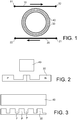
figure 1 est une vue schématique d'un dispositif conforme à l'invention ; - la
figure 2 est une vue en coupe radiale des premier et deuxième guide d'onde en anneau du dispositif selon l'invention ; - la
figure 3 est une vue de côté des premier et deuxième guide d'onde en anneau du dispositif selon l'invention, sur une portion de leur circonférence ; - la
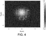
figure 4 illustre la répartition du mode optique entre les deux guides d'onde en anneau du dispositif selon l'invention.
- the
figure 1 is a schematic view of a device according to the invention; - the
figure 2 is a view in radial section of the first and second ring waveguides of the device according to the invention; - the
figure 3 is a side view of the first and second ring waveguides of the device according to the invention, over a portion of their circumference; - the
figure 4 illustrates the distribution of the optical mode between the two ring waveguides of the device according to the invention.
En référence à la
Le premier guide d'onde de bus 10 comporte un port d'entrée 11, communément désigné par port « In », pour recevoir le signal optique à moduler ou à commuter et un port de sortie 12, communément désigné par port « Through ». Le deuxième guide d'onde de bus 20 comporte un port d'entrée 21, communément désigné par port « Add », et un port de sortie 22, communément désigné par port « Drop ».The
Le premier guide d'onde en anneau 30 présente par exemple un rayon de 40µm. On cherche de préférence à avoir un rayon le plus important possible pour augmenter le facteur de qualité du dispositif et son efficacité de modulation/commutation. Mais a contrario, ce rayon est limité de par la fréquence maximale de modulation/commutation souhaitée. L'invention pourra à cet égard trouver avantageusement application pour réaliser des commutateurs pour lesquels la fréquence de commutation doit être inférieure à 1GHz, voire à quelques centaines de MHz.The
Le premier guide d'onde en anneau 30 est formé en un premier matériau dans lequel est réalisée, typiquement par dopage, au moins une jonction p-n ou p-i-n. En faisant varier le potentiel électrique aux bornes de cette jonction, on crée une variation de la concentration des porteurs dans la cavité résonante ce qui engendre une translation de sa résonance dans le spectre optique. Le premier matériau est typiquement du silicium. Le premier matériau peut également être du germanium ou un matériau III-V.The
Dans le cadre d'une application de commutation, la variation du potentiel électrique aux bornes de la jonction permet de faire passer l'anneau résonnant :
- d'un état « ON » où il est résonant à la longueur d'onde du signal optique reçu au port « In » 11 et permet de faire passer ce signal du premier guide de
bus 10 au deuxième guide debus 20 où on le retrouve sur le port de sortie « Drop » 22 ; - à un état « OFF » où sa fréquence de résonance n'est plus accordée avec la longueur d'onde du signal optique reçu au port « In » 11, le signal optique restant dans le même guide de
bus 10 de sorte qu'on le retrouve sur le port de sortie « Through » 12.
- an “ON” state where it is resonant to the wavelength of the optical signal received at the “In”
port 11 and allows this signal to pass from thefirst bus guide 10 to thesecond bus guide 20 where it is found on the “Drop”output port 22; - to an “OFF” state where its resonant frequency is no longer tuned to the wavelength of the optical signal received at the “In”
port 11, the optical signal remaining in thesame bus guide 10 so that it is found on the "Through"output port 12.
Le cas de la modulation est plus générique et implique que le signal disponible sur le port de sortie « Drop » 22 soit ajusté à différents niveaux intermédiaires entre « ON » et « OFF », la puissance optique du signal à moduler étant pour cela partiellement commutée entre les ports de sortie « Through » et « Drop ».The modulation case is more generic and implies that the signal available on the “Drop”
Dans le cadre de l'invention, le dispositif de modulation/commutation comporte un second guide d'onde en anneau 40 agencé axialement en regard du premier guide d'onde en anneau 30. Le premier et le second guide d'onde en anneau se font ainsi face, i.e. ils sont agencés en vis-à-vis l'un de l'autre. Le premier et le second guide d'onde sont ainsi superposés, avec ou non un espace entre eux.In the context of the invention, the modulation / switching device comprises a
On a représenté sur la
Sur ces figures, les deux guides d'onde en anneau 30, 40 sont espacés l'un de l'autre, par exemple d'une distance de 200nm. La distance séparant les deux guides d'onde en anneau 30, 40 doit rester suffisamment faible pour assurer un couplage optique entre les deux guides d'onde en anneau. Cette distance est d'une manière générale inférieure à 400nm, et dans un mode de réalisation possible les deux guides d'onde en anneau peuvent même être accolés l'un à l'autre. Dans un empilement photonique, le second guide d'onde en anneau peut être au-dessus ou en-dessous du premier guide d'onde en anneau.In these figures, the two
Les dimensions du second guide d'onde en anneau 40 sont choisies de manière à garantir un fonctionnement monomode à la longueur d'onde de travail, par exemple à 1310nm. Le second guide d'onde en anneau 40 peut être un guide en bande (guide strip) ayant par exemple une largeur (transversalement à la direction de propagation de la lumière) de 700nm et une hauteur de 600nm.The dimensions of the
Le premier guide d'onde en anneau 30 peut être un guide à nervure (guide rib) qui présente par exemple une partie centrale de 250 nm de large issue d'une gravure de 250nm de profondeur dans un guide de 300nm de hauteur.The
Sur la
Dans un mode de réalisation alternatif, le premier guide d'onde en anneau peut présenter une pluralité de jonctions p-n ou p-i-n agencées orthogonalement à la direction de propagation de la lumière dans le premier guide d'onde en anneau. Dans ce mode de réalisation, on retrouve ainsi des régions p et n interdigitées le long de la circonférence du premier guide d'onde en anneau.In an alternative embodiment, the first ring waveguide may have a plurality of pn or pin junctions arranged orthogonally to the direction of light propagation in the first ring waveguide. In this mode of embodiment, there are thus regions p and n interdigitated along the circumference of the first ring waveguide.
Le second guide d'onde en anneau 40 est formé en un second matériau qui présente un coefficient thermo-optique inférieur au coefficient thermo-optique du premier matériau du premier guide d'onde en anneau 30. Le second matériau peut être du SiN, du SinO, de l'AIN ou encore être un matériau polymère tel que du PMMA (polyméthacrylate de méthyle). On choisit de préférence des matériaux tels que le coefficient thermo-optique du second matériau est au moins cinq fois plus petit que le coefficient thermo-optique du premier matériau. A titre d'exemple, le coefficient thermo-optique d'un nitrure de silicium peut être de 2.10-5K-1 là où le coefficient thermo-optique du silicium est de 2.10-4K-1, soit jusqu'à dix fois moins selon les conditions de dépôt.The
L'invention propose ainsi d'introduire dans un empilement d'une plateforme photonique une couche supplémentaire en un second matériau moins sensible à la température que le matériau du premier guide d'onde en anneau. Ce second matériau permet de diminuer la sensibilité thermique du dispositif de modulation/commutation de sorte qu'il peut fonctionner sans système actif de rétroaction, à tout le moins pour des variations faibles de température. Les guides d'onde de bus 10, 20 peuvent être réalisés en le second matériau, et être ainsi agencées dans la couche de l'empilement où l'on retrouve le second guide d'onde en anneau. Alternativement, ils peuvent être réalisés en le premier matériau, et être ainsi agencées dans la couche de l'empilement où l'on retrouve le premier guide d'onde en anneau. Dans une réalisation alternative, les guides d'onde de bus peuvent être agencés dans une troisième couche.The invention thus proposes to introduce into a stack of a photonic platform an additional layer of a second material less sensitive to temperature than the material of the first ring waveguide. This second material makes it possible to reduce the thermal sensitivity of the modulation / switching device so that it can operate without an active feedback system, at least for slight variations in temperature. The
L'invention propose donc d'avoir recours à deux couches de matériaux différents pour former les deux guides d'onde en anneau en regard l'un de l'autre, l'un (le premier) assurant la fonction active de modulation/commutation et l'autre (le second) améliorant les propriétés passives de l'anneau. Pour cela le signal optique doit présenter un mode optique réparti sur les deux guides d'onde en anneau 30, 40.The invention therefore proposes to use two layers of different materials to form the two ring waveguides facing each other, one (the first) ensuring the active modulation / switching function. and the other (the second) improving the passive properties of the ring. For this, the optical signal must have an optical mode distributed over the two
Or le second matériau présente un indice généralement beaucoup plus faible que le premier matériau de sorte qu'il est difficile d'obtenir un mode couplé dont la puissance optique serait répartie sur les deux guides d'onde en anneau. A titre d'exemple, pour une longueur d'onde de 1310nm, l'indice du Si est de 3.5 là où l'indice du SiN est de 1.9.However, the second material generally has a much lower index than the first material, so that it is difficult to obtain a coupled mode whose optical power would be distributed over the two ring waveguides. As for example, for a wavelength of 1310nm, the Si index is 3.5 where the SiN index is 1.9.
Pour résoudre ce problème, et comme cela est visible sur la
La réduction de la largeur du premier guide d'onde en anneau permet également de répondre à ce problème, étant entendu que cette largeur ne peut être trop faible au risque de rendre l'alignement des dopages p et n difficilement contrôlable (ce serait par exemple le cas avec une largeur de 150nm).Reducing the width of the first ring waveguide also makes it possible to respond to this problem, it being understood that this width cannot be too small at the risk of making the alignment of the p and n dopings difficult to control (this would the case with a width of 150nm).
Le premier guide d'onde en anneau présente donc le long de sa circonférence un ensemble de fentes radiales F agencées périodiquement, deux fentes successives étant séparées par un plot P du premier matériau. L'épaisseur résiduelle du premier guide d'onde en anneau au niveau des fentes F est de préférence comprise entre 50nm (au-dessous, la résistance électrique d'accès peut être trop élevée) et 100nm (au-dessus, une propagation de modes d'un guide en plaque est susceptible de se produire).The first ring wave guide therefore has along its circumference a set of radial slots F arranged periodically, two successive slots being separated by a pad P of the first material. The residual thickness of the first ring waveguide at the slots F is preferably between 50nm (below, the electrical access resistance may be too high) and 100nm (above, a mode propagation of a plate guide is likely to occur).
La largeur des plots P (dans le sens de propagation de la lumière) est choisie au vu des limites sur le pas du réseau et sur les possibilités de fabrication pour ajuster l'indice effectif du premier guide d'onde en anneau, ce qui va contrôler la répartition du mode optique entre le premier guide d'onde en anneau 30 et le second guide d'onde en anneau 40. La répartition de lumière entre les deux guides d'onde en anneau est donc essentiellement réglée en ajustant la largeur du premier guide d'onde en anneau (transversalement à la direction de propagation de la lumière) et la largeur des plots (selon la direction de propagation de la lumière).The width of the pads P (in the direction of propagation of the light) is chosen in view of the limits on the pitch of the grating and on the manufacturing possibilities for adjusting the effective index of the first ring waveguide, which will controlling the distribution of the optical mode between the
Un compromis doit être trouvé entre un mode principalement dans le second guide d'onde en anneau 40, donc très peu sensible à la température mais avec une modulation/commutation peu efficace et un mode principalement dans le premier guide d'onde en anneau 30, donc avec une modulation/commutation efficace mais sensible à la température.A compromise must be found between a mode mainly in the
Le premier guide d'onde en anneau 30 est un dispositif résonant présentant de bons facteurs de qualité et donc pour lequel la modulation/commutation est particulièrement efficace. En outre, l'efficacité de modulation/commutation peut aussi être améliorée en augmentant l'amplitude du signal électrique de commande de la modulation/commutation. Il est donc possible de favoriser un mode optique principalement dans le second guide d'onde en anneau (pour favoriser l'insensibilité thermique) sans affecter l'efficacité de modulation/commutation. Ainsi, dans un mode de réalisation possible, la répartition de la lumière entre les guides d'onde en anneau est telle que 5% à 10% du signal optique est confiné dans le premier guide d'onde en anneau.The
Ainsi, l'intensité du mode couplé se propageant dans les deux guides d'onde en anneau est dans une large part confinée dans le second guide d'onde en anneau. Le second matériau ayant un indice faible, la rugosité des parois a moins d'importance et le facteur de qualité de l'ensemble s'en trouve augmentée. Les pertes induites par le dopage du premier matériau sont aussi diminuées. Le caractère sub-lambda de la structuration du premier guide d'onde en anneau ne dégrade pas le facteur de qualité. Le facteur de qualité étant important, la résonnance est plus fine. Il est donc possible de faire basculer le modulateur/commutateur avec un taux de recouvrement du mode par le premier matériau relativement faible.Thus, the intensity of the coupled mode propagating in the two ring waveguides is to a large extent confined in the second ring waveguide. The second material having a low index, the roughness of the walls is less important and the quality factor of the assembly is thereby increased. The losses induced by doping the first material are also reduced. The sub-lambda nature of the structuring of the first ring wave guide does not degrade the quality factor. The quality factor being important, the resonance is finer. It is therefore possible to switch the modulator / switch with a relatively low mode overlap rate by the first material.
On a représenté sur la
La sensibilité à la température de l'indice effectif du mode couplé est donnée par la formule suivante: ![]()
![]()
![]()
![]()
![]()
![]()
![]()
![]()
Ainsi, là où la sensibilité thermique dans le cas du seul anneau de silicium est de 1,62 × 10⁻⁴ K -1, elle n'est plus que de 0,29 × 10⁻⁴ K -1 pour l'exemple de réalisation de l'invention soit près de 6 fois moins.Thus, where the thermal sensitivity in the case of the single silicon ring is 1.62 × 10 -4 K -1 , it is only 0.29 × 10 -4 K -1 for the example of realization of the invention is almost 6 times less.
Un raisonnement similaire permet d'estimer les pertes optiques qui ont principalement lieu dans le premier guide d'onde de Si dopé. La simulation de mode permet d'accéder à l'indice imaginaire effectif du mode couplé k = 3 × 10⁻⁶ soit un gain d'un facteur 10 par rapport au cas du seul anneau de silicium. On relèvera que cette estimation ne prend en compte que l'effet des pertes associées au dopage dans le guide en Si, et qu'un gain encore plus important est attendu du fait de la moindre sensibilité à la rugosité dans le guide SiNSimilar reasoning makes it possible to estimate the optical losses which mainly take place in the first doped Si waveguide. The mode simulation provides access to the effective imaginary index of the coupled mode k = 3 × 10 -6, ie a gain of a factor of 10 compared to the case of the single silicon ring. It will be noted that this estimate only takes into account the effect of the losses associated with doping in the Si guide, and that an even greater gain is expected due to the lower sensitivity to roughness in the SiN guide.
Claims (10)
caractérisé en ce qu'il comprend un second guide d'onde en anneau (40) agencé axialement en regard du premier guide d'onde en anneau, en ce que le second guide d'onde en anneau (40) est formé en un second matériau qui présente un coefficient thermo-optique inférieur au coefficient thermo-optique du premier matériau et en ce que le premier guide d'onde en anneau (40) est un réseau sub-longueur d'onde.Device for modulating or switching an optical signal comprising a first ring waveguide (30) formed from a first material in which at least one pn or pin junction is made,
characterized in that it comprises a second ring wave guide (40) arranged axially opposite the first ring wave guide, in that the second ring wave guide (40) is formed in a second material which has a thermo-optical coefficient lower than the thermo-optical coefficient of the first material and in that the first ring waveguide (40) is a subwavelength network.
Applications Claiming Priority (1)
| Application Number | Priority Date | Filing Date | Title |
|---|---|---|---|
| FR1856931A FR3084481B1 (en) | 2018-07-25 | 2018-07-25 | ATHERMAL MODULATOR-SWITCH WITH TWO SUPERIMPOSED RINGS |
Publications (2)
| Publication Number | Publication Date |
|---|---|
| EP3599501A1 true EP3599501A1 (en) | 2020-01-29 |
| EP3599501B1 EP3599501B1 (en) | 2021-10-20 |
Family
ID=65685440
Family Applications (1)
| Application Number | Title | Priority Date | Filing Date |
|---|---|---|---|
| EP19186973.4A Active EP3599501B1 (en) | 2018-07-25 | 2019-07-18 | Heat-absorbing modulator-switch with two stacked rings |
Country Status (3)
| Country | Link |
|---|---|
| US (1) | US10768454B2 (en) |
| EP (1) | EP3599501B1 (en) |
| FR (1) | FR3084481B1 (en) |
Families Citing this family (1)
| Publication number | Priority date | Publication date | Assignee | Title |
|---|---|---|---|---|
| FR3107351B1 (en) | 2020-02-19 | 2022-02-04 | Commissariat Energie Atomique | Structured optical fiber sensor incorporating a tunable Vernier effect laser emission device |
Citations (2)
| Publication number | Priority date | Publication date | Assignee | Title |
|---|---|---|---|---|
| US20090274187A1 (en) * | 2006-01-11 | 2009-11-05 | Koji Kudo | Semiconductor Laser, Module and Optical Transmitter |
| US20140321848A1 (en) * | 2012-01-31 | 2014-10-30 | Fujitsu Limited | Optical transmitter and method for controlling operation state of optical transmitter |
Family Cites Families (16)
| Publication number | Priority date | Publication date | Assignee | Title |
|---|---|---|---|---|
| WO2009055440A2 (en) * | 2007-10-22 | 2009-04-30 | Massachusetts Institute Of Technology | Low-loss bloch wave guiding in open structures and highly compact efficient waveguide-crossing arrays |
| US7583874B2 (en) * | 2007-10-31 | 2009-09-01 | Massachusetts Institute Of Technology | Controlling optical resonances via optically induced potentials |
| US8385698B2 (en) * | 2007-12-12 | 2013-02-26 | Hewlett-Packard Development Company, L.P. | Controllable optical ring resonator having periodically spaced control electrodes |
| JP2009258527A (en) * | 2008-04-21 | 2009-11-05 | Hitachi Ltd | Optical device |
| WO2014142832A1 (en) * | 2013-03-13 | 2014-09-18 | 1Hewlett-Packard Development Company, L.P. | Coupled ring resonator system |
| KR102116977B1 (en) * | 2013-04-11 | 2020-05-29 | 삼성전자 주식회사 | Athermal optical modulator and method of manufacturing the same |
| WO2015129039A1 (en) * | 2014-02-26 | 2015-09-03 | 独立行政法人産業技術総合研究所 | Optical semiconductor device |
| FR3028050B1 (en) | 2014-10-29 | 2016-12-30 | Commissariat Energie Atomique | PRE-STRUCTURED SUBSTRATE FOR THE PRODUCTION OF PHOTONIC COMPONENTS, PHOTONIC CIRCUIT, AND METHOD OF MANUFACTURING THE SAME |
| US10133145B2 (en) * | 2015-01-22 | 2018-11-20 | Agency For Science, Technology And Research | Optical device and method of controlling the same |
| FR3055977B1 (en) | 2016-09-15 | 2018-09-28 | Commissariat A L'energie Atomique Et Aux Energies Alternatives | OPTICAL COUPLING DEVICE |
| FR3056306B1 (en) | 2016-09-20 | 2019-11-22 | Commissariat A L'energie Atomique Et Aux Energies Alternatives | OPTICAL GUIDE HAVING A PSEUDO-GRADIENT INDEX RISE |
| FR3064078B1 (en) * | 2017-03-17 | 2020-07-24 | Commissariat Energie Atomique | OPTOELECTRONIC DEVICE FOR GENERATING A FREQUENCY COMB |
| FR3066616B1 (en) | 2017-05-18 | 2019-06-14 | Commissariat A L'energie Atomique Et Aux Energies Alternatives | GUIDED LIGHT SOURCE, MANUFACTURING METHOD AND USE THEREOF FOR SINGLE PHOTON TRANSMISSION |
| FR3069070A1 (en) | 2017-07-17 | 2019-01-18 | Commissariat A L'energie Atomique Et Aux Energies Alternatives | OPTICAL FOCUSING DEVICE WITH INDEX PSEUDO GRADIENT |
| FR3070507B1 (en) | 2017-08-31 | 2019-09-13 | Commissariat A L'energie Atomique Et Aux Energies Alternatives | OPTICAL PHASE MATRIX WITH SIMPLIFIED ADDRESSING |
| FR3071626B1 (en) | 2017-09-26 | 2019-11-01 | Commissariat A L'energie Atomique Et Aux Energies Alternatives | OPTICAL COUPLING DEVICE FOR A PHOTONIC CIRCUIT. |
-
2018
- 2018-07-25 FR FR1856931A patent/FR3084481B1/en active Active
-
2019
- 2019-07-18 EP EP19186973.4A patent/EP3599501B1/en active Active
- 2019-07-22 US US16/518,141 patent/US10768454B2/en active Active
Patent Citations (2)
| Publication number | Priority date | Publication date | Assignee | Title |
|---|---|---|---|---|
| US20090274187A1 (en) * | 2006-01-11 | 2009-11-05 | Koji Kudo | Semiconductor Laser, Module and Optical Transmitter |
| US20140321848A1 (en) * | 2012-01-31 | 2014-10-30 | Fujitsu Limited | Optical transmitter and method for controlling operation state of optical transmitter |
Non-Patent Citations (5)
| Title |
|---|
| BISWAJEET GUHA ET AL: "Athermal silicon microring resonators with titanium oxide cladding", OPTICS EXPRESS, vol. 21, no. 22, 28 October 2013 (2013-10-28), pages 26557, XP055207093, DOI: 10.1364/OE.21.026557 * |
| DE PADMARAJU ET AL.: "Integrated thermal stabilization of a microring modulator", OPT. EXP, 2013 |
| GUHA ET AL.: "Athermal silicon microring resonators with titanium oxide cladding", OPT. EXP., 2013 |
| MOHAMMAD SOLTANI ET AL: "Enabling arbitrary wavelength frequency combs on chip : Enabling arbitrary wavelength frequency combs on chip", LASER & PHOTONICS REVIEWS, vol. 10, no. 1, 1 January 2016 (2016-01-01), DE, pages 158 - 162, XP055440273, ISSN: 1863-8880, DOI: 10.1002/lpor.201500226 * |
| PADMARAJU K ET AL: "Integrated thermal stabilization of a microring modulator", OPTICAL FIBER COMMUNICATION CONFERENCE AND EXPOSITION AND THE NATIONAL FIBER OPTIC ENGINEERS CONFERENCE (OFC/NFOEC), 2013, IEEE, 17 March 2013 (2013-03-17), pages 1 - 3, XP032678941, ISBN: 978-1-4799-0457-0, [retrieved on 20130614] * |
Also Published As
| Publication number | Publication date |
|---|---|
| FR3084481A1 (en) | 2020-01-31 |
| US20200033645A1 (en) | 2020-01-30 |
| FR3084481B1 (en) | 2021-07-23 |
| EP3599501B1 (en) | 2021-10-20 |
| US10768454B2 (en) | 2020-09-08 |
Similar Documents
| Publication | Publication Date | Title |
|---|---|---|
| Komljenovic et al. | Heterogeneous silicon photonic integrated circuits | |
| EP2411863B1 (en) | Semiconductor-on-insulator broadband optical modulator | |
| Bowers et al. | Recent advances in silicon photonic integrated circuits | |
| CN111224312B (en) | Tunable SOI laser | |
| Tang et al. | 50 Gb/s hybrid silicon traveling-wave electroabsorption modulator | |
| US8559470B2 (en) | Method and system for hybrid integration of a tunable laser and a phase modulator | |
| US20130235890A1 (en) | Tunable hybrid laser with carrier-induced phase control | |
| US20170082876A1 (en) | Detector remodulator | |
| EP3015888B1 (en) | Pre-structured substrate for producing photonic components, associated photonic circuit and manufacturing method | |
| JP2010027664A (en) | Optical semiconductor apparatus | |
| EP3190672A1 (en) | Semiconductor laser source | |
| US20210173237A1 (en) | Polarization splitter-rotator with embedded pin structure | |
| EP3869160B1 (en) | Sensor with structured optical fibre including a vernier effect tunable laser emission device | |
| EP3599501B1 (en) | Heat-absorbing modulator-switch with two stacked rings | |
| Dhiman | Silicon photonics: a review | |
| Pommarede et al. | Transmission OVER 50km at 10Gbs/s with a hybrid III-V on silicon integrated tunable laser and electro-absorption modulator | |
| Mandorlo et al. | Controlled multi-wavelength emission in full cmos compatible micro-lasers for on chip interconnections | |
| JP5164897B2 (en) | Optical filter | |
| WO2021004930A1 (en) | Assembly of an active semiconductor component and of a passive silicon-based optical component | |
| Ferrotti | Design, fabrication and characterization of a hybrid III-V on silicon transmitter for high-speed communications | |
| EP3869641B1 (en) | Tunable laser device utilizing vernier effect | |
| Maram et al. | Silicon microring modulator with a pin-diode-loaded multimode interferometer coupler | |
| EP2846424B1 (en) | Integrated optoelectronic device comprising a laser emission section and a section for processing the emitted optical signal | |
| Aihara et al. | Heterogeneously integrated membrane DFB laser and Si Mach-Zehnder modulator on Si photonics platform | |
| Liu et al. | Low-power electro-optical switch based on a iii-v microdisk cavity on a silicon-on-insulator circuit |
Legal Events
| Date | Code | Title | Description |
|---|---|---|---|
| PUAI | Public reference made under article 153(3) epc to a published international application that has entered the european phase |
Free format text: ORIGINAL CODE: 0009012 |
|
| STAA | Information on the status of an ep patent application or granted ep patent |
Free format text: STATUS: REQUEST FOR EXAMINATION WAS MADE |
|
| 17P | Request for examination filed |
Effective date: 20190718 |
|
| AK | Designated contracting states |
Kind code of ref document: A1 Designated state(s): AL AT BE BG CH CY CZ DE DK EE ES FI FR GB GR HR HU IE IS IT LI LT LU LV MC MK MT NL NO PL PT RO RS SE SI SK SM TR |
|
| AX | Request for extension of the european patent |
Extension state: BA ME |
|
| RIC1 | Information provided on ipc code assigned before grant |
Ipc: H04B 10/50 20130101ALI20210331BHEP Ipc: G02F 1/025 20060101ALI20210331BHEP Ipc: G02F 1/015 20060101AFI20210331BHEP |
|
| GRAP | Despatch of communication of intention to grant a patent |
Free format text: ORIGINAL CODE: EPIDOSNIGR1 |
|
| STAA | Information on the status of an ep patent application or granted ep patent |
Free format text: STATUS: GRANT OF PATENT IS INTENDED |
|
| INTG | Intention to grant announced |
Effective date: 20210528 |
|
| GRAS | Grant fee paid |
Free format text: ORIGINAL CODE: EPIDOSNIGR3 |
|
| GRAA | (expected) grant |
Free format text: ORIGINAL CODE: 0009210 |
|
| STAA | Information on the status of an ep patent application or granted ep patent |
Free format text: STATUS: THE PATENT HAS BEEN GRANTED |
|
| AK | Designated contracting states |
Kind code of ref document: B1 Designated state(s): AL AT BE BG CH CY CZ DE DK EE ES FI FR GB GR HR HU IE IS IT LI LT LU LV MC MK MT NL NO PL PT RO RS SE SI SK SM TR |
|
| REG | Reference to a national code |
Ref country code: GB Ref legal event code: FG4D Free format text: NOT ENGLISH |
|
| REG | Reference to a national code |
Ref country code: CH Ref legal event code: EP |
|
| REG | Reference to a national code |
Ref country code: DE Ref legal event code: R096 Ref document number: 602019008481 Country of ref document: DE |
|
| REG | Reference to a national code |
Ref country code: IE Ref legal event code: FG4D Free format text: LANGUAGE OF EP DOCUMENT: FRENCH |
|
| REG | Reference to a national code |
Ref country code: AT Ref legal event code: REF Ref document number: 1440419 Country of ref document: AT Kind code of ref document: T Effective date: 20211115 |
|
| REG | Reference to a national code |
Ref country code: LT Ref legal event code: MG9D |
|
| REG | Reference to a national code |
Ref country code: NL Ref legal event code: MP Effective date: 20211020 |
|
| REG | Reference to a national code |
Ref country code: AT Ref legal event code: MK05 Ref document number: 1440419 Country of ref document: AT Kind code of ref document: T Effective date: 20211020 |
|
| PG25 | Lapsed in a contracting state [announced via postgrant information from national office to epo] |
Ref country code: RS Free format text: LAPSE BECAUSE OF FAILURE TO SUBMIT A TRANSLATION OF THE DESCRIPTION OR TO PAY THE FEE WITHIN THE PRESCRIBED TIME-LIMIT Effective date: 20211020 Ref country code: LT Free format text: LAPSE BECAUSE OF FAILURE TO SUBMIT A TRANSLATION OF THE DESCRIPTION OR TO PAY THE FEE WITHIN THE PRESCRIBED TIME-LIMIT Effective date: 20211020 Ref country code: FI Free format text: LAPSE BECAUSE OF FAILURE TO SUBMIT A TRANSLATION OF THE DESCRIPTION OR TO PAY THE FEE WITHIN THE PRESCRIBED TIME-LIMIT Effective date: 20211020 Ref country code: BG Free format text: LAPSE BECAUSE OF FAILURE TO SUBMIT A TRANSLATION OF THE DESCRIPTION OR TO PAY THE FEE WITHIN THE PRESCRIBED TIME-LIMIT Effective date: 20220120 Ref country code: AT Free format text: LAPSE BECAUSE OF FAILURE TO SUBMIT A TRANSLATION OF THE DESCRIPTION OR TO PAY THE FEE WITHIN THE PRESCRIBED TIME-LIMIT Effective date: 20211020 |
|
| PG25 | Lapsed in a contracting state [announced via postgrant information from national office to epo] |
Ref country code: IS Free format text: LAPSE BECAUSE OF FAILURE TO SUBMIT A TRANSLATION OF THE DESCRIPTION OR TO PAY THE FEE WITHIN THE PRESCRIBED TIME-LIMIT Effective date: 20220220 Ref country code: SE Free format text: LAPSE BECAUSE OF FAILURE TO SUBMIT A TRANSLATION OF THE DESCRIPTION OR TO PAY THE FEE WITHIN THE PRESCRIBED TIME-LIMIT Effective date: 20211020 Ref country code: PT Free format text: LAPSE BECAUSE OF FAILURE TO SUBMIT A TRANSLATION OF THE DESCRIPTION OR TO PAY THE FEE WITHIN THE PRESCRIBED TIME-LIMIT Effective date: 20220221 Ref country code: PL Free format text: LAPSE BECAUSE OF FAILURE TO SUBMIT A TRANSLATION OF THE DESCRIPTION OR TO PAY THE FEE WITHIN THE PRESCRIBED TIME-LIMIT Effective date: 20211020 Ref country code: NO Free format text: LAPSE BECAUSE OF FAILURE TO SUBMIT A TRANSLATION OF THE DESCRIPTION OR TO PAY THE FEE WITHIN THE PRESCRIBED TIME-LIMIT Effective date: 20220120 Ref country code: NL Free format text: LAPSE BECAUSE OF FAILURE TO SUBMIT A TRANSLATION OF THE DESCRIPTION OR TO PAY THE FEE WITHIN THE PRESCRIBED TIME-LIMIT Effective date: 20211020 Ref country code: LV Free format text: LAPSE BECAUSE OF FAILURE TO SUBMIT A TRANSLATION OF THE DESCRIPTION OR TO PAY THE FEE WITHIN THE PRESCRIBED TIME-LIMIT Effective date: 20211020 Ref country code: HR Free format text: LAPSE BECAUSE OF FAILURE TO SUBMIT A TRANSLATION OF THE DESCRIPTION OR TO PAY THE FEE WITHIN THE PRESCRIBED TIME-LIMIT Effective date: 20211020 Ref country code: GR Free format text: LAPSE BECAUSE OF FAILURE TO SUBMIT A TRANSLATION OF THE DESCRIPTION OR TO PAY THE FEE WITHIN THE PRESCRIBED TIME-LIMIT Effective date: 20220121 Ref country code: ES Free format text: LAPSE BECAUSE OF FAILURE TO SUBMIT A TRANSLATION OF THE DESCRIPTION OR TO PAY THE FEE WITHIN THE PRESCRIBED TIME-LIMIT Effective date: 20211020 |
|
| REG | Reference to a national code |
Ref country code: DE Ref legal event code: R097 Ref document number: 602019008481 Country of ref document: DE |
|
| PG25 | Lapsed in a contracting state [announced via postgrant information from national office to epo] |
Ref country code: SM Free format text: LAPSE BECAUSE OF FAILURE TO SUBMIT A TRANSLATION OF THE DESCRIPTION OR TO PAY THE FEE WITHIN THE PRESCRIBED TIME-LIMIT Effective date: 20211020 Ref country code: SK Free format text: LAPSE BECAUSE OF FAILURE TO SUBMIT A TRANSLATION OF THE DESCRIPTION OR TO PAY THE FEE WITHIN THE PRESCRIBED TIME-LIMIT Effective date: 20211020 Ref country code: RO Free format text: LAPSE BECAUSE OF FAILURE TO SUBMIT A TRANSLATION OF THE DESCRIPTION OR TO PAY THE FEE WITHIN THE PRESCRIBED TIME-LIMIT Effective date: 20211020 Ref country code: EE Free format text: LAPSE BECAUSE OF FAILURE TO SUBMIT A TRANSLATION OF THE DESCRIPTION OR TO PAY THE FEE WITHIN THE PRESCRIBED TIME-LIMIT Effective date: 20211020 Ref country code: DK Free format text: LAPSE BECAUSE OF FAILURE TO SUBMIT A TRANSLATION OF THE DESCRIPTION OR TO PAY THE FEE WITHIN THE PRESCRIBED TIME-LIMIT Effective date: 20211020 Ref country code: CZ Free format text: LAPSE BECAUSE OF FAILURE TO SUBMIT A TRANSLATION OF THE DESCRIPTION OR TO PAY THE FEE WITHIN THE PRESCRIBED TIME-LIMIT Effective date: 20211020 |
|
| PLBE | No opposition filed within time limit |
Free format text: ORIGINAL CODE: 0009261 |
|
| STAA | Information on the status of an ep patent application or granted ep patent |
Free format text: STATUS: NO OPPOSITION FILED WITHIN TIME LIMIT |
|
| 26N | No opposition filed |
Effective date: 20220721 |
|
| PG25 | Lapsed in a contracting state [announced via postgrant information from national office to epo] |
Ref country code: AL Free format text: LAPSE BECAUSE OF FAILURE TO SUBMIT A TRANSLATION OF THE DESCRIPTION OR TO PAY THE FEE WITHIN THE PRESCRIBED TIME-LIMIT Effective date: 20211020 |
|
| PG25 | Lapsed in a contracting state [announced via postgrant information from national office to epo] |
Ref country code: SI Free format text: LAPSE BECAUSE OF FAILURE TO SUBMIT A TRANSLATION OF THE DESCRIPTION OR TO PAY THE FEE WITHIN THE PRESCRIBED TIME-LIMIT Effective date: 20211020 |
|
| PG25 | Lapsed in a contracting state [announced via postgrant information from national office to epo] |
Ref country code: MC Free format text: LAPSE BECAUSE OF FAILURE TO SUBMIT A TRANSLATION OF THE DESCRIPTION OR TO PAY THE FEE WITHIN THE PRESCRIBED TIME-LIMIT Effective date: 20211020 |
|
| REG | Reference to a national code |
Ref country code: CH Ref legal event code: PL |
|
| REG | Reference to a national code |
Ref country code: BE Ref legal event code: MM Effective date: 20220731 |
|
| PG25 | Lapsed in a contracting state [announced via postgrant information from national office to epo] |
Ref country code: LU Free format text: LAPSE BECAUSE OF NON-PAYMENT OF DUE FEES Effective date: 20220718 Ref country code: LI Free format text: LAPSE BECAUSE OF NON-PAYMENT OF DUE FEES Effective date: 20220731 Ref country code: CH Free format text: LAPSE BECAUSE OF NON-PAYMENT OF DUE FEES Effective date: 20220731 |
|
| PG25 | Lapsed in a contracting state [announced via postgrant information from national office to epo] |
Ref country code: IT Free format text: LAPSE BECAUSE OF FAILURE TO SUBMIT A TRANSLATION OF THE DESCRIPTION OR TO PAY THE FEE WITHIN THE PRESCRIBED TIME-LIMIT Effective date: 20211020 Ref country code: BE Free format text: LAPSE BECAUSE OF NON-PAYMENT OF DUE FEES Effective date: 20220731 |
|
| PG25 | Lapsed in a contracting state [announced via postgrant information from national office to epo] |
Ref country code: IE Free format text: LAPSE BECAUSE OF NON-PAYMENT OF DUE FEES Effective date: 20220718 |
|
| PGFP | Annual fee paid to national office [announced via postgrant information from national office to epo] |
Ref country code: GB Payment date: 20230724 Year of fee payment: 5 |
|
| PGFP | Annual fee paid to national office [announced via postgrant information from national office to epo] |
Ref country code: FR Payment date: 20230720 Year of fee payment: 5 Ref country code: DE Payment date: 20230720 Year of fee payment: 5 |
|
| PG25 | Lapsed in a contracting state [announced via postgrant information from national office to epo] |
Ref country code: HU Free format text: LAPSE BECAUSE OF FAILURE TO SUBMIT A TRANSLATION OF THE DESCRIPTION OR TO PAY THE FEE WITHIN THE PRESCRIBED TIME-LIMIT; INVALID AB INITIO Effective date: 20190718 |