EP3599480A1 - Lüfter mit integriertem sensor - Google Patents
Lüfter mit integriertem sensor Download PDFInfo
- Publication number
- EP3599480A1 EP3599480A1 EP19187553.3A EP19187553A EP3599480A1 EP 3599480 A1 EP3599480 A1 EP 3599480A1 EP 19187553 A EP19187553 A EP 19187553A EP 3599480 A1 EP3599480 A1 EP 3599480A1
- Authority
- EP
- European Patent Office
- Prior art keywords
- vehicle
- sensor
- impeller
- control device
- ventilation device
- Prior art date
- Legal status (The legal status is an assumption and is not a legal conclusion. Google has not performed a legal analysis and makes no representation as to the accuracy of the status listed.)
- Granted
Links
Images

Classifications
-
- B—PERFORMING OPERATIONS; TRANSPORTING
- B60—VEHICLES IN GENERAL
- B60H—ARRANGEMENTS OF HEATING, COOLING, VENTILATING OR OTHER AIR-TREATING DEVICES SPECIALLY ADAPTED FOR PASSENGER OR GOODS SPACES OF VEHICLES
- B60H1/00—Heating, cooling or ventilating devices
- B60H1/00457—Ventilation unit, e.g. combined with a radiator
-
- G—PHYSICS
- G01—MEASURING; TESTING
- G01S—RADIO DIRECTION-FINDING; RADIO NAVIGATION; DETERMINING DISTANCE OR VELOCITY BY USE OF RADIO WAVES; LOCATING OR PRESENCE-DETECTING BY USE OF THE REFLECTION OR RERADIATION OF RADIO WAVES; ANALOGOUS ARRANGEMENTS USING OTHER WAVES
- G01S17/00—Systems using the reflection or reradiation of electromagnetic waves other than radio waves, e.g. lidar systems
- G01S17/88—Lidar systems specially adapted for specific applications
- G01S17/93—Lidar systems specially adapted for specific applications for anti-collision purposes
- G01S17/931—Lidar systems specially adapted for specific applications for anti-collision purposes of land vehicles
-
- G—PHYSICS
- G01—MEASURING; TESTING
- G01S—RADIO DIRECTION-FINDING; RADIO NAVIGATION; DETERMINING DISTANCE OR VELOCITY BY USE OF RADIO WAVES; LOCATING OR PRESENCE-DETECTING BY USE OF THE REFLECTION OR RERADIATION OF RADIO WAVES; ANALOGOUS ARRANGEMENTS USING OTHER WAVES
- G01S7/00—Details of systems according to groups G01S13/00, G01S15/00, G01S17/00
- G01S7/48—Details of systems according to groups G01S13/00, G01S15/00, G01S17/00 of systems according to group G01S17/00
- G01S7/481—Constructional features, e.g. arrangements of optical elements
- G01S7/4817—Constructional features, e.g. arrangements of optical elements relating to scanning
-
- B—PERFORMING OPERATIONS; TRANSPORTING
- B60—VEHICLES IN GENERAL
- B60H—ARRANGEMENTS OF HEATING, COOLING, VENTILATING OR OTHER AIR-TREATING DEVICES SPECIALLY ADAPTED FOR PASSENGER OR GOODS SPACES OF VEHICLES
- B60H1/00—Heating, cooling or ventilating devices
- B60H1/00642—Control systems or circuits; Control members or indication devices for heating, cooling or ventilating devices
- B60H1/00735—Control systems or circuits characterised by their input, i.e. by the detection, measurement or calculation of particular conditions, e.g. signal treatment, dynamic models
- B60H1/00792—Arrangement of detectors
-
- B—PERFORMING OPERATIONS; TRANSPORTING
- B60—VEHICLES IN GENERAL
- B60H—ARRANGEMENTS OF HEATING, COOLING, VENTILATING OR OTHER AIR-TREATING DEVICES SPECIALLY ADAPTED FOR PASSENGER OR GOODS SPACES OF VEHICLES
- B60H1/00—Heating, cooling or ventilating devices
- B60H1/00642—Control systems or circuits; Control members or indication devices for heating, cooling or ventilating devices
- B60H1/00814—Control systems or circuits characterised by their output, for controlling particular components of the heating, cooling or ventilating installation
- B60H1/00821—Control systems or circuits characterised by their output, for controlling particular components of the heating, cooling or ventilating installation the components being ventilating, air admitting or air distributing devices
-
- B—PERFORMING OPERATIONS; TRANSPORTING
- B60—VEHICLES IN GENERAL
- B60H—ARRANGEMENTS OF HEATING, COOLING, VENTILATING OR OTHER AIR-TREATING DEVICES SPECIALLY ADAPTED FOR PASSENGER OR GOODS SPACES OF VEHICLES
- B60H1/00—Heating, cooling or ventilating devices
- B60H1/00642—Control systems or circuits; Control members or indication devices for heating, cooling or ventilating devices
- B60H1/00814—Control systems or circuits characterised by their output, for controlling particular components of the heating, cooling or ventilating installation
- B60H1/00878—Control systems or circuits characterised by their output, for controlling particular components of the heating, cooling or ventilating installation the components being temperature regulating devices
-
- G—PHYSICS
- G01—MEASURING; TESTING
- G01S—RADIO DIRECTION-FINDING; RADIO NAVIGATION; DETERMINING DISTANCE OR VELOCITY BY USE OF RADIO WAVES; LOCATING OR PRESENCE-DETECTING BY USE OF THE REFLECTION OR RERADIATION OF RADIO WAVES; ANALOGOUS ARRANGEMENTS USING OTHER WAVES
- G01S17/00—Systems using the reflection or reradiation of electromagnetic waves other than radio waves, e.g. lidar systems
- G01S17/88—Lidar systems specially adapted for specific applications
- G01S17/89—Lidar systems specially adapted for specific applications for mapping or imaging
-
- G—PHYSICS
- G01—MEASURING; TESTING
- G01S—RADIO DIRECTION-FINDING; RADIO NAVIGATION; DETERMINING DISTANCE OR VELOCITY BY USE OF RADIO WAVES; LOCATING OR PRESENCE-DETECTING BY USE OF THE REFLECTION OR RERADIATION OF RADIO WAVES; ANALOGOUS ARRANGEMENTS USING OTHER WAVES
- G01S7/00—Details of systems according to groups G01S13/00, G01S15/00, G01S17/00
- G01S7/48—Details of systems according to groups G01S13/00, G01S15/00, G01S17/00 of systems according to group G01S17/00
- G01S7/481—Constructional features, e.g. arrangements of optical elements
- G01S7/4811—Constructional features, e.g. arrangements of optical elements common to transmitter and receiver
- G01S7/4813—Housing arrangements
-
- G—PHYSICS
- G06—COMPUTING OR CALCULATING; COUNTING
- G06V—IMAGE OR VIDEO RECOGNITION OR UNDERSTANDING
- G06V20/00—Scenes; Scene-specific elements
- G06V20/50—Context or environment of the image
- G06V20/56—Context or environment of the image exterior to a vehicle by using sensors mounted on the vehicle
-
- H—ELECTRICITY
- H05—ELECTRIC TECHNIQUES NOT OTHERWISE PROVIDED FOR
- H05K—PRINTED CIRCUITS; CASINGS OR CONSTRUCTIONAL DETAILS OF ELECTRIC APPARATUS; MANUFACTURE OF ASSEMBLAGES OF ELECTRICAL COMPONENTS
- H05K7/00—Constructional details common to different types of electric apparatus
- H05K7/20—Modifications to facilitate cooling, ventilating, or heating
- H05K7/20009—Modifications to facilitate cooling, ventilating, or heating using a gaseous coolant in electronic enclosures
- H05K7/20136—Forced ventilation, e.g. by fans
-
- H—ELECTRICITY
- H05—ELECTRIC TECHNIQUES NOT OTHERWISE PROVIDED FOR
- H05K—PRINTED CIRCUITS; CASINGS OR CONSTRUCTIONAL DETAILS OF ELECTRIC APPARATUS; MANUFACTURE OF ASSEMBLAGES OF ELECTRICAL COMPONENTS
- H05K7/00—Constructional details common to different types of electric apparatus
- H05K7/20—Modifications to facilitate cooling, ventilating, or heating
- H05K7/20845—Modifications to facilitate cooling, ventilating, or heating for automotive electronic casings
-
- H—ELECTRICITY
- H05—ELECTRIC TECHNIQUES NOT OTHERWISE PROVIDED FOR
- H05K—PRINTED CIRCUITS; CASINGS OR CONSTRUCTIONAL DETAILS OF ELECTRIC APPARATUS; MANUFACTURE OF ASSEMBLAGES OF ELECTRICAL COMPONENTS
- H05K7/00—Constructional details common to different types of electric apparatus
- H05K7/20—Modifications to facilitate cooling, ventilating, or heating
- H05K7/2089—Modifications to facilitate cooling, ventilating, or heating for power electronics, e.g. for inverters for controlling motor
- H05K7/20945—Thermal management, e.g. inverter temperature control
-
- B—PERFORMING OPERATIONS; TRANSPORTING
- B60—VEHICLES IN GENERAL
- B60R—VEHICLES, VEHICLE FITTINGS, OR VEHICLE PARTS, NOT OTHERWISE PROVIDED FOR
- B60R11/00—Arrangements for holding or mounting articles, not otherwise provided for
- B60R2011/0042—Arrangements for holding or mounting articles, not otherwise provided for characterised by mounting means
- B60R2011/008—Adjustable or movable supports
- B60R2011/0085—Adjustable or movable supports with adjustment by rotation in their operational position
-
- G—PHYSICS
- G05—CONTROLLING; REGULATING
- G05D—SYSTEMS FOR CONTROLLING OR REGULATING NON-ELECTRIC VARIABLES
- G05D1/00—Control of position, course, altitude or attitude of land, water, air or space vehicles, e.g. using automatic pilots
- G05D1/02—Control of position or course in two dimensions
- G05D1/021—Control of position or course in two dimensions specially adapted to land vehicles
- G05D1/0231—Control of position or course in two dimensions specially adapted to land vehicles using optical position detecting means
Definitions
- the invention relates to a vehicle with a rotatably mounted sensor, set up to create an image of an environment of the vehicle, and a control device, set up to process data received from the sensor.
- the invention relates to a method for creating an image of an environment of a vehicle, with the step of rotating an impeller of a ventilation device set up to cool a control device of the vehicle.
- the recipient If the recipient is not to be found when the object is delivered, for example because he is working as a professional within the delivery times, he will either try to deliver the object again or the object will be in a branch of the delivery company, in a packing station, in a parcel box , deposited with a neighbor or the like for later collection by the recipient.
- Autonomous vehicles use sensors, in particular lidar sensors, to create an image of an environment of the vehicle, on the basis of which the vehicle moves autonomously along a predetermined or dynamically created route.
- lidar sensors represent a central element for autonomous locomotion, since the sensors deliver solid volume data regardless of the surrounding light conditions.
- lidar sensors in particular three-dimensional, 3D, lidar sensors are still expensive.
- the problem is solved by using a vehicle a rotatably mounted sensor, set up to create an image of an environment of the vehicle, a control device set up to process data received from the sensor. and a ventilation device configured to cool the control device by means of a rotatably mounted impeller, wherein the ventilation device and the sensor are rotationally coupled in such a way that the impeller also rotates the sensor about an axis of rotation.
- the control device is set up to move the vehicle autonomously, to calculate the image of the surroundings based on the environmental data obtained from the sensor and / or to move the vehicle autonomously depending on the created image.
- the control device can on the one hand process data received from the sensor, for example in order to create an electronic map of the environment, or to move the vehicle autonomously, in particular on the basis of the electronic map created.
- a high computing power that generates waste heat is regularly necessary for such control and / or computing tasks.
- the senor in particular a lidar sensor, is rotationally coupled to the impeller. If a 2D lidar is now used as a sensor, the rotary motion coupling has the effect that a three-dimensional image of the surroundings of the vehicle can be detected.
- the rotary movement generated anyway by the ventilation device for the impeller for the purpose of cooling the control device is transmitted to the sensor by the rotary movement coupling, so that the sensor also rotates about the axis of rotation.
- the proposed device can be used to easily capture the three-dimensional image of the surroundings of the vehicle, since the 2D lidar sensor can supply three-dimensional volume data of the surroundings of the vehicle due to the rotary movement . Since the wheels and lidar sensors of autonomous vehicles often rotate at the same speed, for example 5 to 10 revolutions per minute, it is advisable, as suggested, to couple the wheel and sensor to one another in order to transmit the rotational movement of the wheel to the sensor.
- the proposed vehicle treads a completely new path, since in the state of the art sensors, in particular lidar sensors, and ventilation devices of autonomous vehicles are always designed separately and in particular are not motion-coupled.
- the vehicle can be designed in different ways, which also includes a passenger car, abbreviated to a car, a delivery truck, a robot trolley, a picking truck or a truck.
- the vehicle preferably has a driver's cabin, behind which a loading space or a loading area for transporting objects is arranged.
- the vehicle is preferably designed as a delivery vehicle in order to transfer objects, for example, between a logistics center, "warehouse", warehouse and / or distribution center and recipients or senders of the objects.
- the recipients or senders of the objects can be people, packing stations and / or the aforementioned logistics centers, "warehouses", warehouses or distribution centers.
- the vehicle can also be used in a personalized manner by a deliverer along a predetermined or self-made route in order to transfer the objects to and / or take them to one or more destinations.
- the vehicle can preferably autonomously travel a predetermined or self-stretched distance and stop independently at one or more destinations at which an object can be removed from and / or parked in the loading space.
- the loading space can be designed as an open loading area with side, front and / or rear doors and / or flaps.
- the loading space can particularly preferably be completely closed by means of the doors against external influences, in particular weather influences, so that unauthorized third parties have no access to the objects transported in the loading space.
- the loading space further preferably has a cuboid volume and / or the loading space is provided with a rectangular base area as loading space and / or floor on which the objects can be placed next to one another and / or one above the other.
- the useful volume of the loading space can be, for example, ⁇ 4, ⁇ 8, or ⁇ 20 m 3 , so that objects with a weight of, for example, 650 kg, 1000 kg or 1350 kg can be transported as the payload.
- the loading space preferably has a rectangular and / or flat usable area on which the objects can be received, in particular stacked.
- the object can be any transportable object, in particular a product, a piece goods and / or a shipment.
- the object can be everyday items such as consumables or food as well as technical objects or equipment. Consignments such as, for example, letters, parcels and / or print products such as brochures, brochures or magazines can also be included.
- the control device preferably comprises a computer and / or computer which is provided with software in order to maneuver the vehicle on the basis of environmental data obtained from the sensor.
- the axis of rotation preferably extends in the direction of the surface normal of the loading area.
- rotationally coupled means either a rigid connection or a connection such that the sensor can also rotate independently of the impeller, for example can rotate faster than the impeller, but a rotational movement of the impeller is transmitted to the sensor in the manner of a “driving function”.
- the axis of rotation of the impeller is oriented orthogonally to a direction of travel of the vehicle.
- the control device can be set up to move the vehicle autonomously depending on the created image.
- the control device can be set up for the vehicle to move on the basis of predetermined data, for example on the basis of an electronic map.
- the ventilation device can be designed in any way.
- the ventilation device is designed as a radial fan.
- the ventilation device can also be designed as an axial fan.
- the impeller preferably has blades in order to extract waste heat from the control device.
- the ventilation device is preferably arranged and designed to extract waste heat from the control device and / or to extract waste heat from a driver's cabin of the vehicle. Control devices and possibly other systems available for autonomous driving in the vehicle not infrequently produce waste heat of more than 500 W due to the high computing power required for autonomous driving, which must be dissipated by the ventilation device in order for the vehicle to operate properly.
- the ventilation device is arranged above the control device and connected to it in such a way that the impeller sucks air in particular from an interior of the control device.
- the impeller can also extract external heat from the control device.
- the ventilation device is preferred arranged touching and / or adjacent above the control device.
- the ventilation device is further preferably designed to suck air out of the driver's cabin, as a result of which the driver's cab can be air-conditioned.
- the ventilation device can be designed to supply air heated by the control device to the driver's cab for heating the same.
- the ventilation device is further preferably designed to optionally supply heated air to the driver's cab by the control device and / or to extract air from the driver's cab.
- the senor, the control device and / or the ventilation device is provided in an exposed position on the vehicle.
- the sensor can detect the widest possible environment and thus a large-scale image of the surroundings of the vehicle, so that the control device can recognize obstacles at an early stage and / or create a map of the surroundings.
- the sensor, the control device and / or the ventilation device is arranged on a roof of the vehicle, in particular on and / or on a roof of a driver's cab of the vehicle, for example under a windshield of the roof.
- the sensor, the control device and the ventilation device are particularly preferably arranged one above the other on the roof of the driver's cab and / or a driver's cabin of the vehicle.
- the sensor is very particularly preferably arranged directly above and / or in one piece with the ventilation device.
- the impeller can be driven by a driving wind and / or by a motor.
- lateral openings can be provided in it, into which the head wind can flow and in this way can set the impeller in rotary motion.
- An additional motor if necessary, can be switched on in support and / or when the vehicle is at a standstill in order to ensure a minimum speed of the impeller and thus a minimum cooling capacity of the ventilation device.
- the cooling of the control device can be effected in a particularly energy-saving manner by such a configuration.
- the impeller and the sensor have a common axis of rotation.
- a coupling is preferably provided on the common axis of rotation, by means of which a rotary movement of the impeller is transmitted to the sensor, while the sensor can also rotate independently of the impeller.
- the ventilation device and the sensor are rotationally coupled by means of a gear.
- the gearbox has a gear ratio of 2: 1 or 3: 1. If the impeller requires a higher speed than the sensor to achieve minimum cooling, this higher speed can be set by the gear.
- the sensor is designed as a lidar sensor.
- a lidar sensor preferably sends out laser pulses and detects light scattered back from the atmosphere. A distance to the location of a scatter is calculated from a light propagation time of the impulses and thus the image of the surroundings is created.
- the lidar sensor can emit laser pulses and measure a distance to a surface of the surroundings reflecting the laser pulses using a so-called time-of-flight method.
- the sensor is preferably designed as a 2D lidar sensor.
- the 2D sensor is further preferably arranged such that, when the sensor is stationary, the 2D sensor can produce an image of the vertical as a two-dimensional image of the surroundings only in the direction of the vertical.
- the senor has a mirror which can be pivoted with respect to the horizontal.
- the sensor preferably has a motor by means of which the mirror can be pivoted. By swiveling the mirror, an image of the vertical can be created. By rotating the sensor and thus the mirror about the axis of rotation, which is preferred when the vehicle is not pivoted relative to the horizontal runs in the direction of the vertical, an image of the horizontal can also be created in order to obtain a three-dimensional image of the surroundings of the vehicle.
- the method comprises the step: Autonomous movement of the vehicle depending on the image created by the control device.
- the proposed method advantageously allows a three-dimensional image of the surroundings of the vehicle to be created, for example by means of a 2D lidar sensor.
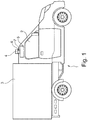
- Fig. 1 shows a vehicle 1 according to a preferred embodiment of the invention in a schematic side view.
- the vehicle 1 is designed as a battery-operated delivery vehicle with a driver's cabin 2 and a closed charging cabin 3 located behind it.
- objects of different types can be transferred without any human interaction, for example between a logistics center and a recipient and / or sender of the object.
- the vehicle 1 has a sensor 4 designed as a 2D lidar sensor, which in an exposed position on the vehicle 1 is arranged on a roof of the driver's cab 2 and is orthogonal to a loading area and / or the direction of travel of the vehicle 1 extending sensor axis of rotation is rotatably mounted.
- the sensor 4 has an all-round view that is limited only to the rear by the loading cabin 3.
- the lidar sensor 4 emits laser pulses and uses a so-called time-of-flight method to measure a distance from a surface of the surroundings reflecting the laser pulses, in order to create the image of the surroundings in this way.
- the vehicle 1 also has a computer-based control device 5, which is set up to autonomously move the vehicle 1 along a defined or dynamically determined route based on the image obtained by the sensor 4.
- the control device 5 can have further electrical components for autonomously controlling the vehicle 1.
- the control device 5 is also arranged on the roof of the driver's cab 2.
- a ventilation device 6 in the form of a radial fan is also provided, which has a rotatably mounted impeller 7, indicated in FIG Fig. 1 , An axis of rotation of the impeller 7 is oriented orthogonally to the loading area or the direction of travel of the vehicle 1.
- the control device 5 is arranged in direct contact on the roof of the driver's cab 2, so that waste heat can be extracted from an interior of the control device 5 by the impeller 7, indicated by an arrow. Touching the control device 5, the ventilation device 6 is initially spaced from the roof and subsequently the sensor 4 at the highest point above the roof.
- Fig. 2 shows the arrangement of the roof of the driver's cab 2, control device 5, ventilation device 6 with impeller 7 and sensor 4 in detail.
- Sensor 4 and impeller 7 are coupled to one another in such a way that the impeller 7 rotates the sensor 4 about the axis of rotation during a rotational movement.
- sensor 4 and impeller 7 have a rotationally coupled common axis such that on the one hand the impeller 7 driven by the driving wind or by a motor provided within the ventilation device 6 transmits a rotary movement of the impeller 7 to the sensor 4.
- the axis of rotation of the impeller 7 and the sensor axis of rotation of the sensor 4 coincide and are connected to one another in a rotationally coupled manner by two shafts running into one another and / or by a gear.
- the senor 4 can have its own motor in order to rotate the sensor 4 about the sensor axis of rotation. Since the sensor 4 can be rotated by the impeller 7 in this way, the proposed solution allows a 2D lidar 4 to be upgraded to a 3D lidar 4 in a simple manner: the sensor rotates due to the rotary movement transmitted from the impeller 7 to the sensor 4 4 around the sensor axis of rotation.
- a 2D lidar 4 is now pivoted orthogonally on the ventilation device 6, which would only record a two-dimensional image of a plane parallel to the vertical without a rotary movement provided by a mirror 8 which can be pivoted relative to the horizontal, one leads due to the Coupling of motion by the impeller to the sensor 4, rotary motion about the axis of rotation so that a three-dimensional image of the surroundings can be detected by the 2D lidar 4.
- Fig. 2 is the mirror 8 on the one hand by the rotary motion coupling in the Fig. 2 referred to as the Z-axis rotated sensor axis and on the other hand pivoted about the Y-axis by a motor of the sensor 4.
Landscapes
- Engineering & Computer Science (AREA)
- Physics & Mathematics (AREA)
- Thermal Sciences (AREA)
- Microelectronics & Electronic Packaging (AREA)
- General Physics & Mathematics (AREA)
- Remote Sensing (AREA)
- Radar, Positioning & Navigation (AREA)
- Computer Networks & Wireless Communication (AREA)
- Mechanical Engineering (AREA)
- Electromagnetism (AREA)
- Multimedia (AREA)
- Theoretical Computer Science (AREA)
- Optical Radar Systems And Details Thereof (AREA)
Abstract
Description
- Die Erfindung betrifft ein Fahrzeug mit einem drehbar gelagerten Sensor, eingerichtet ein Abbild einer Umgebung des Fahrzeugs zu erstellen, und einer Steuerungseinrichtung, eingerichtet von dem Sensor erhaltene Daten zu verarbeiten. Die Erfindung betrifft ein Verfahren zum Erstellen eines Abbilds einer Umgebung eines Fahrzeugs, mit dem Schritt Drehen eines Laufrads einer Ventilationseinrichtung, eingerichtet eine Steuerungseinrichtung des Fahrzeugs zu kühlen.
- Infolge steigenden Güterverkehrs durch Stück- und Sammelgutfahrten, LKW- oder Containertransporte, See- oder Luftfrachtpakettransporte im Rahmen von E-Commerce und Online-Versandhandelsangeboten hat sich die Anzahl an Transportgütern und insbesondere von Paketsendungen, Sendungen oder sonstigen transportablen Gütern, nachfolgend allgemein als Objekte bezeichnet, signifikant erhöht. Zwar ist es heutzutage möglich, eine Bestellung unabhängig von herkömmlichen Ladenöffnungszeiten Online zu tätigen, jedoch erfolgt die Lieferung des Objektes an den Empfänger fast ausschließlich mittels klassischer Zustellverfahren, beispielsweise durch Briefträger oder im Falle von Paketsendungen durch motorisierte Zustellfahrzeuge und im Wesentlichen nur innerhalb der Ladenöffnungszeiten. Ist der Empfänger bei der Lieferung des Objektes nicht anzutreffen, beispielsweise weil er als Berufstätiger innerhalb der Zustellzeiten seiner Arbeit nachgeht, wird entweder versucht, das Objekt ein weiteres Mal zuzustellen oder das Objekt wird in einer Filiale des Zustellunternehmens, in einer Packstation, in einem Paketkasten, bei einem Nachbarn oder dergleichen zur späteren Abholung durch den Empfänger hinterlegt.
- In jüngster Zeit sind daher Versuche unternommen worden, Objekte mittels unbemannter, autonomer Fahrzeuge an den Empfänger oder an eine Fachanlagenvorrichtung als Sammelpunkt zu liefern, beispielsweise an eine Packstation, welche im öffentlichen Raum für einen Stadtbezirk für eine Mehrzahl Empfänger oder im Vorgarten eines Hauses des Empfängers aufgestellt ist. Das Objekt kann außerhalb der Ladenöffnungs- oder Zustellzeiten aus der Fachanlagenvorrichtung entnommen oder in diese eingestellt werden.
- Autonome Fahrzeuge verwenden Sensoren, insbesondere Lidar-Sensoren, um ein Abbild einer Umgebung des Fahrzeugs zu erstellen, anhand dessen sich das Fahrzeug autonom entlang einer vorgegebenen oder dynamisch erstellten Route fortbewegt. Derartige Lidar-Sensoren stellen ein zentrales Element für die autonome Fortbewegung dar, da die Sensoren solide Volumendaten unabhängig von umgebenden Lichtbedingungen liefern. Trotz fortschreitender Verbreitung autonomer Fahrzeuge sind Lidar Sensoren, insbesondere dreidimensionale, 3D, Lidar-Sensoren noch immer kostenaufwendig.
- Ausgehend von dieser Situation ist es eine Aufgabe der vorliegenden Erfindung, ein Fahrzeug mit einem Sensor zum Erstellen eines Abbilds einer Umgebung des Fahrzeugs anzugeben, welcher im Vergleich zu aus dem Stand der Technik bekannten Sensoren günstiger herstellbar ist.
- Die Aufgabe der Erfindung wird durch die Merkmale des unabhängigen Anspruchs gelöst. Vorteilhafte Ausgestaltungen sind in den Unteransprüchen angegeben.
- Demnach wird die Aufgabe gelöst durch ein Fahrzeug mit
einem drehbar gelagerten Sensor, eingerichtet ein Abbild einer Umgebung des Fahrzeugs zu erstellen,
einer Steuerungseinrichtung, eingerichtet von dem Sensor erhaltene Daten zu verarbeiten. und
einer Ventilationseinrichtung, eingerichtet zum Kühlen der Steuerungseinrichtung mittels eines drehbar gelagerten Laufrads, wobei
die Ventilationseinrichtung und der Sensor derart drehbewegungsgekoppelt sind, dass das Laufrad den Sensor um eine Drehachse mitdreht. - Nach einer bevorzugten Weiterbildung ist die Steuerungseinrichtung eingerichtet, das Fahrzeug autonom fortzubewegen, anhand von dem Sensor erhaltenen Umgebungsdaten das Abbild der Umgebung zu berechnen und/oder das Fahrzeug in Abhängigkeit des erstellten Abbilds autonom fortzubewegen. Die Steuerungseinrichtung kann also einerseits von dem Sensor erhaltene Daten verarbeiten, beispielsweise um eine elektronische Karte der Umgebung zu erstellen, oder das Fahrzeug insbesondere anhand der erstellten elektronische Karte autonom fortzubewegen. In jeden Fall ist für derartige Steuerungs- und/oder Rechenaufgaben regelmäßig eine hohe Rechenleistungen notwendig, die Abwärme generiert.
- Ein wesentlicher Aspekt liegt darin, dass der Sensor, insbesondere ein Lidar-Sensor, drehbewegungsgekoppelt mit dem Laufrad ist. Sofern nun ein 2D-Lidar als Sensor verwendet wird, bewirkt die Drehbewegungskopplung, dass ein dreidimensionales Abbild der Umgebung des Fahrzeugs erfassbar ist. Die durch die Ventilationseinrichtung ohnehin für das Laufrad zwecks Kühlung der Steuerungseinrichtung erzeugte Drehbewegung wird durch die Drehbewegungskopplung auf den Sensor übertragen, so dass sich dieser um die Drehachse mitdreht. Sofern nun beispielsweise ein 2D-Lidar Sensor orthogonal verschwenkt als Sensor vorgesehen ist, kann durch die vorgeschlagene Vorrichtung in einfacher Weise das dreidimensionale Abbild der Umgebung des Fahrzeugs erfasst werden, da der 2D-Lidar Sensor durch die Drehbewegung dreidimensionale Volumendaten der Umgebung des Fahrzeugs liefern kann. Da Laufräder und Lidar-Sensoren autonomer Fahrzeuge sich oftmals mit gleicher Drehzahl von beispielsweise 5 bis 10 Umdrehungen pro Minute drehen, bietet sich wie vorgeschlagen an, Laufrad und Sensor miteinander zu koppeln, um die Drehbewegung des Laufrads auf den Sensor zu übertragen. Allerdings beschreitet das vorgeschlagene Fahrzeug einen ganz neuen Weg, da im Stand der Technik Sensoren, insbesondere Lidar-Sensoren, und Ventilationseinrichtungen autonomer Fahrzeuge immer separat und gerade nicht bewegungsgekoppelt ausgestaltet sind.
- Das Fahrzeug kann in unterschiedlicher Weise ausgestaltet sein, wobei ebenso ein Personenkraftwagen, abgekürzt PKW, ein Lieferwagen, ein Robotor-Rollwagen, ein Kommissionierwagen oder ein Lastkraftwagen mit umfasst ist. Bevorzugt weist das Fahrzeug eine Fahrerkabine auf, hinter der ein Laderaum oder eine Ladefläche zum Transportieren von Objekten angeordnet ist. Das Fahrzeug ist bevorzugt als Zustellfahrzeug ausgeführt, um Objekte beispielweise zwischen einem Logistikzentrum, "Warehouse", Lager und/oder Verteilzentrum und Empfängern bzw. Absendern der Objekte zu überbringen. Bei den Empfängern bzw. Absendern der Objekte kann es sich um Personen, Packstationen und/oder vorgenannte Logistikzentren, "Warehouses", Lager oder Verteilzentren handeln. Das Fahrzeug kann neben einer bevorzugten autonomen Fahrweise ebenso personifiziert durch einen Zusteller entlang einer vorgegebenen oder selbst zusammengestellten Wegstrecke eingesetzt werden, um die Objekte an einen oder mehrere Zielorte zu überbringen und/oder an diesen aufzunehmen. Grundsätzlich jedoch kann das Fahrzeug bevorzugt autonom eine vorgegebene oder selbst zusammengestreckte Wegstrecke zurücklegen und selbstständig an einem oder mehreren Zielorten anhalten, an denen ein Objekt aus dem Laderaum entnehmbar ist und/oder in diesem abstellbar ist.
- Der Laderaum kann als offene Ladefläche mit seitlichen, vorderen und/oder hinteren Türen und/oder Klappen ausgeführt sein. Besonders bevorzugt ist der Laderaum mittels der Türen gegen äußere Einflüsse insbesondere Witterungseinflüsse vollständig verschließbar, so dass unberechtigte Dritte keinen Zugriff auf die in dem Laderaum transportierten Objekte haben. Weiter bevorzugt weist der Laderaum ein quaderartiges Volumen auf und/oder ist der Laderaum mit einer rechteckigen Grundfläche als Ladefläche und/oder Boden versehen, auf dem die Objekte nebeneinander und/oder übereinander abstellbar sind. Das Nutzvolumen des Laderaums kann beispielsweise ≥ 4, ≥ 8, oder ≥ 20 m3 betragen, so dass als Nutzlast Objekte mit einem Gewicht von beispielsweise 650 kg, 1000 kg oder 1350 kg transportierbar sind. Der Laderaum weist bevorzugt eine rechteckige und/oder ebene Nutzfläche auf, auf der die Objekte aufnehmbar, insbesondere stapelbar sind.
- Bei dem Objekt kann es sich um einen beliebigen transportablen Gegenstand handeln, insbesondere um eine Ware, ein Stückgut und/oder eine Sendung. Das Objekt kann Gegenstände des täglichen Bedarfs, wie beispielsweise Verbrauchsmaterialien oder Lebensmittel sowie technische Gegenstände oder Gerätschaften umfassen. Ebenso können Sendungen wie beispielsweise Briefsendungen, Paketsendungen und/oder Print-Produkte wie Prospekte, Broschüren oder Zeitschriften umfasst sein. Die Steuerungseinrichtung umfasst bevorzugt einen Rechner und/oder Computer, der mit einer Software versehen ist, um anhand von von dem Sensor erhaltenen Umgebungsdaten das Fahrzeug zu manövrieren. Die Drehachse erstreckt sich bevorzugt in Richtung der Flächennormalen der Ladefläche. Der Begriff drehbewegungsgekoppelt meint entweder eine starre Verbindung oder eine Verbindung derart, dass sich der Sensor auch unabhängig von dem Laufrad drehen kann, beispielsweise schneller als das Laufrad drehen kann, jedoch eine Drehbewegung des Laufrads nach Art einer "Mitnahmefunktion" auf den Sensor übertragen wird. In bevorzugter Weiterbildung ist die Drehachse des Laufrads orthogonal zu einer Fortbewegungsrichtung des Fahrzeugs orientiert. Die Steuerungseinrichtung kann eingerichtet sein, das Fahrzeug in Abhängigkeit des erstellten Abbildes autonom fortzubewegen. Alternativ oder zusätzlich kann die Steuerungseinrichtung eingerichtet sein, dass Fahrzeug anhand vorgegebener Daten, beispielsweise anhand einer elektronischen Karte, fortbewegen.
- Grundsätzlich kann die Ventilationseinrichtung beliebig ausgestaltet sein. Gemäß einer bevorzugten Weiterbildung ist die Ventilationseinrichtung als Radiallüfter ausgeführt. Ebenso kann die Ventilationseinrichtung als Axialventilator ausgeführt sein. Das Laufrad weist bevorzugt Schaufeln auf, um Abwärme der Steuerungseinrichtung abzusaugen. Die Ventilationseinrichtung ist bevorzugt angeordnet und ausgestaltet, Abwärme der Steuerungseinrichtung abzusaugen und/oder Abwärme aus einer Fahrerkabine des Fahrzeugs abzusaugen. Steuerungseinrichtungen und gegebenenfalls weitere für autonomes Fahren in dem Fahrzeug vorhandene Systeme produzieren nicht selten aufgrund der für das autonome Fahren benötigten hohen Rechenleistung Abwärme von mehr als 500 W, die durch die Ventilationseinrichtung zum einwandfreien Betrieb des Fahrzeugs abzuführen ist.
- Gemäß einer bevorzugten Weiterbildung ist die Ventilationseinrichtung oberhalb der Steuerungseinrichtung angeordnet und mit dieser derart verbunden, dass das Laufrad insbesondere aus einem Innenraum der Steuerungseinrichtung Luft absaugt. Ebenso kann das Laufrad Außenwärme der Steuerungseinrichtung absaugen. Bevorzugt ist die Ventilationseinrichtung berührend und/oder angrenzend oberhalb der Steuerungseinrichtung angeordnet. Weiter bevorzugt ist die Ventilationseinrichtung ausgeführt, aus der Fahrerkabine Luft abzusaugen, wodurch sich eine Klimatisierung des Fahrerhauses erreichen lässt. Ebenso kann die Ventilationseinrichtung ausgeführt sein, durch die Steuerungseinrichtung erwärmte Luft dem Fahrerhaus zum Beheizen desselben zuzuführen. Weiter bevorzugt ist die Ventilationseinrichtung ausgeführt, wahlweise dem Fahrerhaus durch die Steuerungseinrichtung erwärmte Luft zuzuführen und/oder aus dem Fahrerhaus Luft abzusaugen.
- Gemäß einer anderen bevorzugten Weiterbildung ist der Sensor, die Steuerungseinrichtung und/oder die Ventilationseinrichtung an einer exponierten Position an dem Fahrzeug vorgesehen. Durch Anordnen an einer exponierten Position kann der Sensor ein möglichst weites Umfeld und damit weiträumiges Abbild der Umgebung des Fahrzeugs erfassen, so dass die Steuerungseinrichtung frühzeitig Hindernisse erkennen und/oder eine Karte der Umgebung erstellen kann. In diesem Zusammenhang ist weiter bevorzugt, dass der Sensor, die Steuerungseinrichtung und/oder die Ventilationseinrichtung an einem Dach des Fahrzeugs, insbesondere an und/oder auf einem Dach eines Fahrerhauses des Fahrzeugs, beispielsweise unter einem Windschild des Dachs, angeordnet ist. Besonders bevorzugt sind der Sensor, die Steuerungseinrichtung und die Ventilationseinrichtung übereinander auf dem Dach des Fahrerhauses und/oder einer Fahrerkabine des Fahrzeugs angeordnet. Ganz besonders bevorzugt ist der Sensor oberhalb der Ventilationseinrichtung, unmittelbar angrenzend und/oder einstückig mit dieser angeordnet.
- Gemäß einer anderen bevorzugten Weiterbildung ist das Laufrad durch Fahrwind und/oder durch einen Motor antreibbar. Zum Antreiben des Laufrads durch Fahrtwind können an diesem seitliche Öffnungen vorgesehen sein, in welche der Fahrtwind einströmen und derart das Laufrad in Drehbewegung versetzen kann. Ein gegebenenfalls zusätzlicher Motor kann unterstützend und/oder bei Stillstand des Fahrzeugs zugeschaltet werden, um eine Mindestdrehzahl des Laufrads und damit Mindestkühlleistung der Ventilationseinrichtung sicherzustellen. Im Falle eines batteriebetriebenen Fahrzeugs lässt sich durch eine solche Ausgestaltung die Kühlung der Steuerungseinrichtung besonders energiesparend bewirken.
- Nach einer anderen bevorzugten Weiterbildung weisen das Laufrad und der Sensor eine gemeinsame Drehachse auf. Bevorzugt ist an der gemeinsamen Drehachse eine Kupplung vorgesehen, durch welche eine Drehbewegung des Laufrads auf den Sensor übertragen wird, während der Sensor sich auch unabhängig von dem Laufrad drehen kann. Gemäß einer noch anderen bevorzugten Weiterbildung sind die Ventilationseinrichtung und der Sensor mittels eines Getriebes drehbewegungsgekoppelt. Das Getriebe weist beispielsweise ein Übersetzungsverhältnis von 2:1 oder 3:1 auf. Sofern das Laufrad zum Erzielen einer Mindestkühlung eine höhere Drehzahl als der Sensor benötigt, lässt sich diese höhere Drehzahl durch das Getriebe einstellen.
- Zum Ausgestalten des Sensors existieren grundsätzlich verschiedene Möglichkeiten. Gemäß einer besonders bevorzugten Weiterbildung ist der Sensor als Lidar-Sensor ausgebildet. Ein Lidar-Sensor sendet bevorzugt Laserimpulse aus und detektiert aus der Atmosphäre zurückgestreutes Licht. Aus einer Lichtlaufzeit der Impulse wird eine Entfernung zum Ort einer Streuung berechnet und derart das Abbild der Umgebung erstellt. Ebenso kann der Lidar Sensor Laserpulse aussenden und über ein sogenanntes Time-of-Flight Verfahren einen Abstand zu einer die Laserpulse reflektierenden Oberfläche der Umgebung messen. Bevorzugt ist der Sensor als 2D-Lidar Sensor ausgebildet. Weiter bevorzugt ist der 2D-Sensor derart angeordnet, dass, bei feststehendem Sensor, durch den 2D-Sensor ein Abbild der Vertikalen, als ein zweidimensionales Abbild der Umgebung nur in Richtung der Vertikalen, erstellbar ist. Durch Drehen des 2D-Sensors um die Drehachse lässt sich in vorteilhafter Weise ein dreidimensionales Abbild der Umgebung des Fahrzeugs erstellen, ohne dass dazu ein im Vergleich zu einem 2D-Lidar Sensor ein wesentlich kostenintensiverer 3D-Lidar Sensor und derart ein wesentlich komplexerer technischer Aufbau benötigt wird.
- Gemäß einer noch anderen bevorzugten Weiterbildung weist der Sensor einen gegenüber der Horizontalen verschwenkbaren Spiegel auf. Bevorzugt weist der Sensor einen Motor auf, mittels dessen der Spiegel verschwenkbar ist. Durch Verschwenken des Spiegels lässt sich ein Abbild der Vertikalen erstellen. Durch Verdrehen des Sensors und damit des Spiegels um die Drehachse, die bei gegenüber der Horizontalen unverschwenktem Fahrzeug bevorzugt in Richtung der Vertikalen verläuft, lässt sich zudem ein Abbild der Horizontalen erstellen, um im Ergebnis ein dreidimensionales Abbild der Umgebung des Fahrzeugs zu erhalten.
- Die Aufgabe der Erfindung wird zudem durch ein Verfahren zum Erstellen eines Abbilds einer Umgebung eines Fahrzeugs gelöst, mit den Schritten:
- Drehen eines Laufrads einer Ventilationseinrichtung, eingerichtet eine Steuerungseinrichtung des Fahrzeugs zu kühlen, und
- Mitdrehen eines mit dem Laufrad drehbewegungsgekoppelten Sensors, eingerichtet das Abbild der Umgebung des Fahrzeugs zu erstellen, um eine Drehachse.
- Gemäß einer bevorzugten Weiterbildung umfasst das Verfahren den Schritt:
Autonomes Fortbewegen des Fahrzeugs in Abhängigkeit des erstellten Abbilds durch die Steuerungseinrichtung. - Das vorgeschlagene Verfahren erlaubt in vorteilhafter Weise beispielsweise mittels eines 2D-Lidar Sensors ein dreidimensionales Abbild der Umgebung des Fahrzeugs zu erstellen.
- Weiterbildungen des Verfahrens sowie Vorteile desselben ergeben sich für den Fachmann in Analogie zu dem zuvor beschriebenen Fahrzeug.
- Nachfolgend wird die Erfindung unter Bezugnahme auf die anliegenden Zeichnungen anhand bevorzugter Ausführungsbeispiele näher erläutert.
- In den Zeichnungen zeigen
- Fig. 1
- eine schematische Ansicht eines Fahrzeugs gemäß einem bevorzugten Ausführungsbeispiel der Erfindung in einer Seitansicht, und
- Fig. 2
- einen Ausschnitt des Fahrzeugs gemäß
Fig. 1 . -
Fig. 1 zeigt ein Fahrzeug 1 gemäß einem bevorzugten Ausführungsbeispiel der Erfindung in einer schematischen Seitansicht. Das Fahrzeug 1 ist als batteriebetriebener Lieferwagen mit Fahrerkabine 2 und dahinter liegender, geschlossener Ladekabine 3 ausgeführt. Mittels des bevorzugt autonom ausgeführten Fahrzeugs 1 lassen sich Objekte unterschiedlicher Art beispielsweise zwischen einem Logistikzentrum und einem Empfänger und/oder Absender des Objektes gänzlich ohne menschliche Interaktion überbringen. - Zum Erzeugen eines Abbildes einer Umgebung des Fahrzeugs 1 weist das Fahrzeug 1 einen als 2D-Lidar Sensor ausgebildeten Sensor 4 auf, der an einer exponierten Position an dem Fahrzeug 1 vorliegend auf einem Dach der Fahrerkabine 2 angeordnet und um eine sich orthogonal zu einer Ladefläche und/oder Fortbewegungsrichtung des Fahrzeugs 1 erstreckende Sensordrehachse drehbar gelagert ist. Derart hat der Sensor 4 einen nur rückwärtig durch die Ladekabine 3 begrenzten Rundumblick. Der Lidar-Sensor 4 sendet Laserpulse aus und misst mittels eines sogenannten Time-of-Flight Verfahrens einen Abstand zu einer die Laserpulse reflektierenden Oberfläche der Umgebung, um derart das Abbild der Umgebung zu erstellen.
- Das Fahrzeug 1 weist ferner eine computerbasierte Steuerungseinrichtung 5 auf, welche eingerichtet ist, das Fahrzeug 1 aufgrund des durch den Sensor 4 erhaltenen Abbilds autonom entlang einer festgelegten oder dynamisch bestimmten Route fortzubewegen. Die Steuerungseinrichtung 5 kann weitere elektrische Komponenten zum autonomen Steuern des Fahrzeugs 1 aufweisen. Die Steuerungseinrichtung 5 ist ebenso auf dem Dach der Fahrerkabine 2 angeordnet.
- Um Abwärme der Steuerungseinrichtung 5 von nicht selten mehr als 500 W abzuführen, ist ferner eine Ventilationseinrichtung 6 in Form eines Radiallüfters vorgesehen, welche ein drehbar gelagertes Laufrad 7 aufweist, angedeutet in
Fig. 1 . Eine Drehachse des Laufrads 7 ist orthogonal zu der Ladefläche bzw. der Fortbewegungsrichtung des Fahrzeugs 1 orientiert ist. Die Steuerungseinrichtung 5 ist unmittelbar berührend auf dem Dach der Fahrerkabine 2 angeordnet, so dass durch das Laufrad 7 Abwärme aus einem Innenraum der Steuerungseinrichtung 5 absaugbar ist, angedeutet durch einen Pfeil. Berührend auf der Steuerungseinrichtung 5 ist beabstandet von dem Dach zunächst die Ventilationseinrichtung 6 und in der Folge am höchsten Punkt über dem Dach der Sensor 4 angeordnet.Fig. 2 zeigt die Anordnung von Dach der Fahrerkabine 2, Steuerungseinrichtung 5, Ventilationseinrichtung 6 mit Laufrad 7 und Sensor 4 im Detail. - Sensor 4 und Laufrad 7 sind drehbewegungsgekoppelt derart miteinander verbunden, dass das Laufrad 7 bei einer Drehbewegung den Sensor 4 um die Drehachse mitdreht. Dazu weisen Sensor 4 und Laufrad 7 eine dreh gekoppelte gemeinsame Achse derart auf, dass einerseits das durch Fahrwind oder durch einen innerhalb der Ventilationseinrichtung 6 vorgesehenen Motor angetriebene Laufrad 7 eine Drehbewegung des Laufrads 7 auf den Sensor 4 überträgt. Drehachse des Laufrads 7 und Sensordrehachse des Sensors 4 stimmen überein und sind durch zwei ineinanderlaufende Wellen und/oder über ein Getriebe miteinander drehbewegungsgekoppelt verbunden.
- Ebenso kann der Sensor 4 einen eigenen Motor aufweisen, um den Sensor 4 um die Sensordrehachse zu drehen. Da der Sensor 4 derart durch das Laufrad 7 drehbar ist, lässt sich durch die vorgeschlagene Lösung ein 2D-Lidar 4 in einfacher Weise zum einem 3D-Lidar 4 aufwerten: Durch die von dem Laufrad 7 auf den Sensor 4 übertragene Drehbewegung dreht sich der Sensor 4 um die Sensordrehachse. Sofern nun beispielsweise ein 2D-Lidar 4 orthogonal verschwenkt auf der Ventilationseinrichtung 6 angeordnet wird, welcher ohne Drehbewegung durch einen an dem Sensor 4 vorgesehenen gegenüber der Horizontalen verschwenkbaren Spiegel 8 nur ein zweidimensionales Abbild einer Ebene parallel zu der Vertikalen aufnehmen würde, führt eine aufgrund der Bewegungskopplung durch das Laufrad auf den Sensor 4 übertragene Drehbewegung um die Drehachse dazu, dass durch den 2D-Lidar 4 ein dreidimensionales Abbildung der Umgebung erfassbar ist. Bezugnehmend auf
Fig. 2 wird der Spiegel 8 einerseits durch die Drehbewegungskoppelung um die in derFig. 2 als Z-Achse bezeichnete Sensordrehachse verdreht und andererseits durch einen Motor des Sensors 4 um die Y-Achse verschwenkt. - Die beschriebenen Ausführungsbeispiele sind lediglich Beispiele, die im Rahmen der Ansprüche auf vielfältige Weise modifiziert und/oder ergänzt werden können. Jedes Merkmal, das für ein bestimmtes Ausführungsbeispiel beschrieben wurde, kann eigenständig oder in Kombination mit anderen Merkmalen in einem beliebigen anderen Ausführungsbeispiel genutzt werden. Jedes Merkmal, dass für ein Ausführungsbeispiel einer bestimmten Kategorie beschrieben wurde, kann auch in entsprechender Weise in einem Ausführungsbeispiel einer anderen Kategorie eingesetzt werden.
Bezugszeichenliste Fahrzeug 1 Fahrerkabine 2 Ladekabine 3 Sensor 4 Steuerungseinrichtung 5 Ventilationseinrichtung 6 Laufrad 7 Spiegel 8
Claims (15)
- Fahrzeug (1) mit
einem drehbar gelagerten Sensor (4), eingerichtet ein Abbild einer Umgebung des Fahrzeugs (1) zu erstellen,
einer Steuerungseinrichtung (5), eingerichtet von dem Sensor (4) erhaltene Daten zu verarbeiten und
einer Ventilationseinrichtung (6), eingerichtet zum Kühlen der Steuerungseinrichtung (5) mittels eines drehbar gelagerten Laufrads (2), wobei
die Ventilationseinrichtung (6) und der Sensor (4) derart drehbewegungsgekoppelt sind, dass das Laufrad (7) den Sensor (4) um eine Drehachse mitdreht. - Fahrzeug (1) nach dem vorhergehenden Anspruch, wobei die Steuerungseinrichtung (5) eingerichtet ist, das Fahrzeug (1) autonom fortzubewegen, anhand von dem Sensor (4) erhaltenen Umgebungsdaten das Abbild der Umgebung zu berechnen und/oder das Fahrzeug (1) in Abhängigkeit des erstellten Abbilds autonom fortzubewegen.
- Fahrzeug (1) nach einem der vorhergehenden Ansprüche, wobei die Drehachse des Laufrads (2) orthogonal zu einer Fortbewegungsrichtung des Fahrzeugs (1) orientiert ist.
- Fahrzeug (1) nach einem der vorhergehenden Ansprüche, wobei die Ventilationseinrichtung (6) als Radiallüfter ausgeführt ist.
- Fahrzeug (1) nach einem der vorhergehenden Ansprüche, wobei die Ventilationseinrichtung (1) oberhalb der Steuerungseinrichtung (5) angeordnet und mit dieser derart verbunden ist, dass das Laufrad (7) insbesondere aus einem Innenraum der Steuerungseinrichtung (5) Luft absaugt.
- Fahrzeug (1) nach einem der vorhergehenden Ansprüche, wobei der Sensor (4), die Steuerungseinrichtung (5) und/oder die Ventilationseinrichtung (6) an einer exponierten Position an dem Fahrzeug (1) vorgesehen ist.
- Fahrzeug (1) nach einem der vorhergehenden Ansprüche, wobei der Sensor (4), die Steuerungseinrichtung (5) und/oder die Ventilationseinrichtung (6) an einem Dach des Fahrzeugs (1), insbesondere an einem Dach einer Fahrerkabine (2) des Fahrzeugs (1), angeordnet ist.
- Fahrzeug (2) nach einem der vorhergehenden Ansprüche, wobei der Sensor (4) oberhalb der Ventilationseinrichtung (6) angeordnet ist.
- Fahrzeug (1) nach einem der vorhergehenden Ansprüche, wobei das Laufrad (7) durch Fahrwind und/oder durch einen Motor antreibbar ist.
- Fahrzeug (1) nach einem der vorhergehenden Ansprüche, wobei das Laufrad und der Sensor eine gemeinsame Drehachse aufweisen.
- Fahrzeug (1) nach einem der vorhergehenden Ansprüche, wobei die Ventilationseinrichtung (6) und der Sensor (4) mittels eines Getriebes drehbewegungsgekoppelt sind.
- Fahrzeug (1) nach einem der vorhergehenden Ansprüche, wobei der Sensor (4) als Lidar-Sensor ausgebildet ist
- Fahrzeug (1) nach einem der vorhergehenden Ansprüche, wobei der Sensor (4) einen gegenüber der Horizontalen verschwenkbaren Spiegel (8) aufweist.
- Verfahren zum Erstellen eines Abbilds einer Umgebung eines Fahrzeugs (1), mit den Schritten:Drehen eines Laufrads (2) einer Ventilationseinrichtung (6), eingerichtet eine Steuerungseinrichtung (5) des Fahrzeugs (1) zu kühlen, undMitdrehen eines mit dem Laufrad (2) drehbewegungsgekoppelten Sensors (4), eingerichtet das Abbild der Umgebung des Fahrzeugs (1) zu erstellen, um eine Drehachse.
- Verfahren nach dem vorherigen Anspruch, mit dem Schritt:
Autonomes Fortbewegen des Fahrzeugs (1) in Abhängigkeit des erstellten Abbilds durch die Steuerungseinrichtung (5).
Applications Claiming Priority (1)
| Application Number | Priority Date | Filing Date | Title |
|---|---|---|---|
| DE102018118007.1A DE102018118007A1 (de) | 2018-07-25 | 2018-07-25 | Lüfter mit integriertem Sensor |
Publications (2)
| Publication Number | Publication Date |
|---|---|
| EP3599480A1 true EP3599480A1 (de) | 2020-01-29 |
| EP3599480B1 EP3599480B1 (de) | 2022-09-07 |
Family
ID=67438368
Family Applications (1)
| Application Number | Title | Priority Date | Filing Date |
|---|---|---|---|
| EP19187553.3A Active EP3599480B1 (de) | 2018-07-25 | 2019-07-22 | Lüfter mit integriertem sensor |
Country Status (4)
| Country | Link |
|---|---|
| US (1) | US11609335B2 (de) |
| EP (1) | EP3599480B1 (de) |
| CN (1) | CN110843453B (de) |
| DE (1) | DE102018118007A1 (de) |
Families Citing this family (7)
| Publication number | Priority date | Publication date | Assignee | Title |
|---|---|---|---|---|
| US11041742B2 (en) * | 2019-09-27 | 2021-06-22 | Lyft, Inc. | Secure thermally-managed case for a sensing device |
| US12352900B2 (en) * | 2019-12-20 | 2025-07-08 | Waymo Llc | Light detection and ranging (lidar) device having a light-guide manifold |
| DE102020112311B3 (de) * | 2020-05-06 | 2021-05-20 | Audi Aktiengesellschaft | Kraftfahrzeug mit einem optischen Umgebungssensor und Verfahren zum Betrieb eines Kraftfahrzeugs |
| CA3141724A1 (en) * | 2020-12-30 | 2022-06-30 | Op-Hygiene Ip Gmbh | Smart module with adjustable time of flight sensor |
| DE102022134473A1 (de) * | 2022-12-22 | 2024-06-27 | Pepperl+Fuchs Se | Scanner zum Nachweisen von Objekten in einem Überwachungsbereich |
| DE102023115626A1 (de) * | 2023-06-15 | 2024-12-19 | Webasto SE | Fahrzeugdach, umfassend Sensormodul mit Umfeldsensoranordnung |
| CN118906717B (zh) * | 2024-10-11 | 2024-12-06 | 烟台大学 | 一种汽车轮胎保护装置 |
Citations (2)
| Publication number | Priority date | Publication date | Assignee | Title |
|---|---|---|---|---|
| DE102016201057A1 (de) * | 2016-01-26 | 2017-07-27 | Conti Temic Microelectronic Gmbh | Lidar-vorrichtung, fahrzeug und verfahren zum erfassen eines objekts |
| US20180109061A1 (en) * | 2016-10-17 | 2018-04-19 | Waymo Llc | Thermal Rotary Link |
Family Cites Families (17)
| Publication number | Priority date | Publication date | Assignee | Title |
|---|---|---|---|---|
| JP5462153B2 (ja) * | 2007-05-16 | 2014-04-02 | エルジー イノテック カンパニー リミテッド | 距離測定装置及びその方法 |
| CN102549405B (zh) * | 2009-07-31 | 2015-12-16 | Mts系统公司 | 风力涡轮机传动系统测试组件 |
| US9509357B2 (en) * | 2012-08-17 | 2016-11-29 | Motorola Solutions, Inc. | Removable vehicular rooftop communication system |
| EP3032278B1 (de) * | 2014-12-11 | 2017-03-22 | Sick Ag | Optoelektronischer Sensor |
| US9863403B2 (en) * | 2015-09-23 | 2018-01-09 | Toyota Motor Engineering & Manufacturing North America, Inc. | Wind turbine systems and air channels in vehicles for enhancing energy generation, cooling, and aerodynamics |
| US10527730B2 (en) * | 2015-10-22 | 2020-01-07 | Toyota Motor Engineering & Manufacturing North America, Inc. | Object detection system |
| KR20170071181A (ko) * | 2015-12-15 | 2017-06-23 | 한화테크윈 주식회사 | 회전체 |
| DE102015226502A1 (de) * | 2015-12-22 | 2017-06-22 | Robert Bosch Gmbh | Lidar-Abtasteinrichtung an einem Kraftfahrzeug |
| US9885526B2 (en) * | 2016-03-11 | 2018-02-06 | Ford Global Technologies, Llc | Cooling system for vehicle sensor modules |
| CN106054176A (zh) * | 2016-05-05 | 2016-10-26 | 高世恒 | 一种利用2d雷达实现空间探测的方法 |
| DE102016220708B4 (de) * | 2016-10-21 | 2026-02-19 | Volkswagen Aktiengesellschaft | Lidar-Sensor und Verfahren zum optischen Abtasten einer Umgebung |
| US20180113209A1 (en) * | 2016-10-21 | 2018-04-26 | Waymo Llc | Radar generated occupancy grid for autonomous vehicle perception and planning |
| CN206804857U (zh) * | 2017-05-05 | 2017-12-26 | 杭州欧镭激光技术有限公司 | 具有散热结构的激光探测装置 |
| CN107160958B (zh) * | 2017-05-05 | 2019-07-23 | 浙江零跑科技有限公司 | 一种汽车轮胎降温装置 |
| DE102017216241A1 (de) * | 2017-09-14 | 2019-03-14 | Robert Bosch Gmbh | Lidar-Anordnung mit Strömungskühlung |
| CN107678043A (zh) * | 2017-11-03 | 2018-02-09 | 南京视莱尔汽车电子有限公司 | 一种用于自动驾驶的新型车载雷达装置 |
| CN108020842B (zh) * | 2017-11-22 | 2021-09-28 | 苏州大学 | 一种磁悬浮风力驱动激光扫描雷达 |
-
2018
- 2018-07-25 DE DE102018118007.1A patent/DE102018118007A1/de not_active Ceased
-
2019
- 2019-07-22 EP EP19187553.3A patent/EP3599480B1/de active Active
- 2019-07-22 CN CN201910662287.7A patent/CN110843453B/zh not_active Expired - Fee Related
- 2019-07-24 US US16/520,834 patent/US11609335B2/en active Active
Patent Citations (2)
| Publication number | Priority date | Publication date | Assignee | Title |
|---|---|---|---|---|
| DE102016201057A1 (de) * | 2016-01-26 | 2017-07-27 | Conti Temic Microelectronic Gmbh | Lidar-vorrichtung, fahrzeug und verfahren zum erfassen eines objekts |
| US20180109061A1 (en) * | 2016-10-17 | 2018-04-19 | Waymo Llc | Thermal Rotary Link |
Also Published As
| Publication number | Publication date |
|---|---|
| DE102018118007A1 (de) | 2020-01-30 |
| EP3599480B1 (de) | 2022-09-07 |
| US20200033480A1 (en) | 2020-01-30 |
| CN110843453A (zh) | 2020-02-28 |
| US11609335B2 (en) | 2023-03-21 |
| CN110843453B (zh) | 2023-06-09 |
Similar Documents
| Publication | Publication Date | Title |
|---|---|---|
| EP3599480B1 (de) | Lüfter mit integriertem sensor | |
| DE112016006478B4 (de) | Erweitertes ladungstransportsystem | |
| DE102019131449A1 (de) | Fahrzeug und Zustellsystem | |
| DE102017123491B4 (de) | Fahrzeug zum autonomen Transportieren eines Objektes | |
| WO2017214652A1 (de) | Kommissioniersystem mit einem transportroboter zum unterfahren von einzelregalen und transportwagen | |
| EP3049879A2 (de) | Transportfahrzeug zum transport von lastregalen mit teilweise autonomem fahrbetrieb und verfahren zum betrieb des transportfahrzeugs | |
| WO2015155086A1 (de) | Anordnung zum überbringen einer sendung | |
| EP3559773B1 (de) | Verfahren zur navigation und selbstlokalisierung eines sich autonom fortbewegenden bearbeitungsgerätes | |
| EP3052427A2 (de) | Transportfahrzeug und verfahren zum störungsfreien transport von lastregalen in werkshallen mit funkabschattungen und mit teilweise autonomem fahrbetrieb | |
| DE102019203797B4 (de) | Antriebsvorrichtung für ein Verkehrsmittelwechselsystem und Verkehrsmittelwechselsystem | |
| EP3474205A1 (de) | Energieeffiziente auslieferung von sendungen | |
| EP3543928B1 (de) | Verfahren zum öffnen einer tür eines lieferwagens | |
| DE102016210627B4 (de) | Vorrichtung zum Aufbewahren und Transportieren von Bauteilen und Verfahren zur Versorgung mindestens einer Verarbeitungseinrichtung mit Bauteilen | |
| DE102021200339A1 (de) | Sortiersystem und Verfahren zum Steuern eines Sortiersystems | |
| DE102021121028B4 (de) | Frachtvorrichtung | |
| DE202013008718U1 (de) | Transportfahrzeug zum störungsfreien Transport von Lastregalen in Werkshallen mit Funkabschattungen und mit teilweise autonomem Fahrbetrieb | |
| EP3899825A1 (de) | Verfahren zur autonomen fahrzeugreinigung | |
| DE102022105979A1 (de) | Transportsystem | |
| DE102019212634A1 (de) | Verfahren zum Liefern oder Abholen eines Gegenstands an ein/von einem Kraftfahrzeug, Steuereinrichtung, Koordinationseinrichtung, System zur Übergabe eines vorbestimmten Gegenstands, und Kraftfahrzeug | |
| CN109987015A (zh) | 一种利用微型物流车的自动送货装置及自动送货方法 | |
| DE102019202917A1 (de) | Verfahren zur Lieferung von Artikeln durch ein unbemanntes Luftfahrzeug an ein Kraftfahrzeug | |
| DE102017114875B3 (de) | Verfahren zum Ausliefern von mit einer Zieladresse versehenen Objekten unter Verwendung eines Transportfahrzeugs | |
| CN212637280U (zh) | 一种两栖智能物流配送小车 | |
| DE102025122947A1 (de) | Struktur und Verfahren zum Be-/Entladen von Fracht eines Fahrzeugs | |
| DE202021004425U1 (de) | Logistiksystem zur Planung und Abwicklung von Warensendungen |
Legal Events
| Date | Code | Title | Description |
|---|---|---|---|
| PUAI | Public reference made under article 153(3) epc to a published international application that has entered the european phase |
Free format text: ORIGINAL CODE: 0009012 |
|
| STAA | Information on the status of an ep patent application or granted ep patent |
Free format text: STATUS: THE APPLICATION HAS BEEN PUBLISHED |
|
| AK | Designated contracting states |
Kind code of ref document: A1 Designated state(s): AL AT BE BG CH CY CZ DE DK EE ES FI FR GB GR HR HU IE IS IT LI LT LU LV MC MK MT NL NO PL PT RO RS SE SI SK SM TR |
|
| AX | Request for extension of the european patent |
Extension state: BA ME |
|
| STAA | Information on the status of an ep patent application or granted ep patent |
Free format text: STATUS: REQUEST FOR EXAMINATION WAS MADE |
|
| 17P | Request for examination filed |
Effective date: 20200630 |
|
| RBV | Designated contracting states (corrected) |
Designated state(s): AL AT BE BG CH CY CZ DE DK EE ES FI FR GB GR HR HU IE IS IT LI LT LU LV MC MK MT NL NO PL PT RO RS SE SI SK SM TR |
|
| STAA | Information on the status of an ep patent application or granted ep patent |
Free format text: STATUS: EXAMINATION IS IN PROGRESS |
|
| 17Q | First examination report despatched |
Effective date: 20200925 |
|
| GRAP | Despatch of communication of intention to grant a patent |
Free format text: ORIGINAL CODE: EPIDOSNIGR1 |
|
| STAA | Information on the status of an ep patent application or granted ep patent |
Free format text: STATUS: GRANT OF PATENT IS INTENDED |
|
| INTG | Intention to grant announced |
Effective date: 20220421 |
|
| GRAS | Grant fee paid |
Free format text: ORIGINAL CODE: EPIDOSNIGR3 |
|
| GRAA | (expected) grant |
Free format text: ORIGINAL CODE: 0009210 |
|
| STAA | Information on the status of an ep patent application or granted ep patent |
Free format text: STATUS: THE PATENT HAS BEEN GRANTED |
|
| AK | Designated contracting states |
Kind code of ref document: B1 Designated state(s): AL AT BE BG CH CY CZ DE DK EE ES FI FR GB GR HR HU IE IS IT LI LT LU LV MC MK MT NL NO PL PT RO RS SE SI SK SM TR |
|
| REG | Reference to a national code |
Ref country code: GB Ref legal event code: FG4D Free format text: NOT ENGLISH |
|
| REG | Reference to a national code |
Ref country code: CH Ref legal event code: EP Ref country code: AT Ref legal event code: REF Ref document number: 1517504 Country of ref document: AT Kind code of ref document: T Effective date: 20220915 |
|
| REG | Reference to a national code |
Ref country code: IE Ref legal event code: FG4D Free format text: LANGUAGE OF EP DOCUMENT: GERMAN |
|
| REG | Reference to a national code |
Ref country code: DE Ref legal event code: R096 Ref document number: 502019005547 Country of ref document: DE |
|
| REG | Reference to a national code |
Ref country code: LT Ref legal event code: MG9D |
|
| REG | Reference to a national code |
Ref country code: NL Ref legal event code: MP Effective date: 20220907 |
|
| PG25 | Lapsed in a contracting state [announced via postgrant information from national office to epo] |
Ref country code: SE Free format text: LAPSE BECAUSE OF FAILURE TO SUBMIT A TRANSLATION OF THE DESCRIPTION OR TO PAY THE FEE WITHIN THE PRESCRIBED TIME-LIMIT Effective date: 20220907 Ref country code: RS Free format text: LAPSE BECAUSE OF FAILURE TO SUBMIT A TRANSLATION OF THE DESCRIPTION OR TO PAY THE FEE WITHIN THE PRESCRIBED TIME-LIMIT Effective date: 20220907 Ref country code: NO Free format text: LAPSE BECAUSE OF FAILURE TO SUBMIT A TRANSLATION OF THE DESCRIPTION OR TO PAY THE FEE WITHIN THE PRESCRIBED TIME-LIMIT Effective date: 20221207 Ref country code: LV Free format text: LAPSE BECAUSE OF FAILURE TO SUBMIT A TRANSLATION OF THE DESCRIPTION OR TO PAY THE FEE WITHIN THE PRESCRIBED TIME-LIMIT Effective date: 20220907 Ref country code: LT Free format text: LAPSE BECAUSE OF FAILURE TO SUBMIT A TRANSLATION OF THE DESCRIPTION OR TO PAY THE FEE WITHIN THE PRESCRIBED TIME-LIMIT Effective date: 20220907 Ref country code: FI Free format text: LAPSE BECAUSE OF FAILURE TO SUBMIT A TRANSLATION OF THE DESCRIPTION OR TO PAY THE FEE WITHIN THE PRESCRIBED TIME-LIMIT Effective date: 20220907 |
|
| PG25 | Lapsed in a contracting state [announced via postgrant information from national office to epo] |
Ref country code: HR Free format text: LAPSE BECAUSE OF FAILURE TO SUBMIT A TRANSLATION OF THE DESCRIPTION OR TO PAY THE FEE WITHIN THE PRESCRIBED TIME-LIMIT Effective date: 20220907 Ref country code: GR Free format text: LAPSE BECAUSE OF FAILURE TO SUBMIT A TRANSLATION OF THE DESCRIPTION OR TO PAY THE FEE WITHIN THE PRESCRIBED TIME-LIMIT Effective date: 20221208 |
|
| PG25 | Lapsed in a contracting state [announced via postgrant information from national office to epo] |
Ref country code: SM Free format text: LAPSE BECAUSE OF FAILURE TO SUBMIT A TRANSLATION OF THE DESCRIPTION OR TO PAY THE FEE WITHIN THE PRESCRIBED TIME-LIMIT Effective date: 20220907 Ref country code: RO Free format text: LAPSE BECAUSE OF FAILURE TO SUBMIT A TRANSLATION OF THE DESCRIPTION OR TO PAY THE FEE WITHIN THE PRESCRIBED TIME-LIMIT Effective date: 20220907 Ref country code: PT Free format text: LAPSE BECAUSE OF FAILURE TO SUBMIT A TRANSLATION OF THE DESCRIPTION OR TO PAY THE FEE WITHIN THE PRESCRIBED TIME-LIMIT Effective date: 20230109 Ref country code: ES Free format text: LAPSE BECAUSE OF FAILURE TO SUBMIT A TRANSLATION OF THE DESCRIPTION OR TO PAY THE FEE WITHIN THE PRESCRIBED TIME-LIMIT Effective date: 20220907 Ref country code: CZ Free format text: LAPSE BECAUSE OF FAILURE TO SUBMIT A TRANSLATION OF THE DESCRIPTION OR TO PAY THE FEE WITHIN THE PRESCRIBED TIME-LIMIT Effective date: 20220907 |
|
| PG25 | Lapsed in a contracting state [announced via postgrant information from national office to epo] |
Ref country code: SK Free format text: LAPSE BECAUSE OF FAILURE TO SUBMIT A TRANSLATION OF THE DESCRIPTION OR TO PAY THE FEE WITHIN THE PRESCRIBED TIME-LIMIT Effective date: 20220907 Ref country code: PL Free format text: LAPSE BECAUSE OF FAILURE TO SUBMIT A TRANSLATION OF THE DESCRIPTION OR TO PAY THE FEE WITHIN THE PRESCRIBED TIME-LIMIT Effective date: 20220907 Ref country code: IS Free format text: LAPSE BECAUSE OF FAILURE TO SUBMIT A TRANSLATION OF THE DESCRIPTION OR TO PAY THE FEE WITHIN THE PRESCRIBED TIME-LIMIT Effective date: 20230107 Ref country code: EE Free format text: LAPSE BECAUSE OF FAILURE TO SUBMIT A TRANSLATION OF THE DESCRIPTION OR TO PAY THE FEE WITHIN THE PRESCRIBED TIME-LIMIT Effective date: 20220907 |
|
| REG | Reference to a national code |
Ref country code: DE Ref legal event code: R097 Ref document number: 502019005547 Country of ref document: DE |
|
| PG25 | Lapsed in a contracting state [announced via postgrant information from national office to epo] |
Ref country code: NL Free format text: LAPSE BECAUSE OF FAILURE TO SUBMIT A TRANSLATION OF THE DESCRIPTION OR TO PAY THE FEE WITHIN THE PRESCRIBED TIME-LIMIT Effective date: 20220907 Ref country code: AL Free format text: LAPSE BECAUSE OF FAILURE TO SUBMIT A TRANSLATION OF THE DESCRIPTION OR TO PAY THE FEE WITHIN THE PRESCRIBED TIME-LIMIT Effective date: 20220907 |
|
| P01 | Opt-out of the competence of the unified patent court (upc) registered |
Effective date: 20230526 |
|
| PLBE | No opposition filed within time limit |
Free format text: ORIGINAL CODE: 0009261 |
|
| STAA | Information on the status of an ep patent application or granted ep patent |
Free format text: STATUS: NO OPPOSITION FILED WITHIN TIME LIMIT |
|
| PG25 | Lapsed in a contracting state [announced via postgrant information from national office to epo] |
Ref country code: DK Free format text: LAPSE BECAUSE OF FAILURE TO SUBMIT A TRANSLATION OF THE DESCRIPTION OR TO PAY THE FEE WITHIN THE PRESCRIBED TIME-LIMIT Effective date: 20220907 |
|
| 26N | No opposition filed |
Effective date: 20230608 |
|
| PG25 | Lapsed in a contracting state [announced via postgrant information from national office to epo] |
Ref country code: SI Free format text: LAPSE BECAUSE OF FAILURE TO SUBMIT A TRANSLATION OF THE DESCRIPTION OR TO PAY THE FEE WITHIN THE PRESCRIBED TIME-LIMIT Effective date: 20220907 |
|
| PG25 | Lapsed in a contracting state [announced via postgrant information from national office to epo] |
Ref country code: MC Free format text: LAPSE BECAUSE OF FAILURE TO SUBMIT A TRANSLATION OF THE DESCRIPTION OR TO PAY THE FEE WITHIN THE PRESCRIBED TIME-LIMIT Effective date: 20220907 |
|
| PG25 | Lapsed in a contracting state [announced via postgrant information from national office to epo] |
Ref country code: MC Free format text: LAPSE BECAUSE OF FAILURE TO SUBMIT A TRANSLATION OF THE DESCRIPTION OR TO PAY THE FEE WITHIN THE PRESCRIBED TIME-LIMIT Effective date: 20220907 |
|
| REG | Reference to a national code |
Ref country code: CH Ref legal event code: PL |
|
| REG | Reference to a national code |
Ref country code: BE Ref legal event code: MM Effective date: 20230731 |
|
| PG25 | Lapsed in a contracting state [announced via postgrant information from national office to epo] |
Ref country code: LU Free format text: LAPSE BECAUSE OF NON-PAYMENT OF DUE FEES Effective date: 20230722 |
|
| PG25 | Lapsed in a contracting state [announced via postgrant information from national office to epo] |
Ref country code: LU Free format text: LAPSE BECAUSE OF NON-PAYMENT OF DUE FEES Effective date: 20230722 |
|
| REG | Reference to a national code |
Ref country code: IE Ref legal event code: MM4A |
|
| PG25 | Lapsed in a contracting state [announced via postgrant information from national office to epo] |
Ref country code: CH Free format text: LAPSE BECAUSE OF NON-PAYMENT OF DUE FEES Effective date: 20230731 |
|
| PG25 | Lapsed in a contracting state [announced via postgrant information from national office to epo] |
Ref country code: IT Free format text: LAPSE BECAUSE OF FAILURE TO SUBMIT A TRANSLATION OF THE DESCRIPTION OR TO PAY THE FEE WITHIN THE PRESCRIBED TIME-LIMIT Effective date: 20220907 Ref country code: BE Free format text: LAPSE BECAUSE OF NON-PAYMENT OF DUE FEES Effective date: 20230731 |
|
| PG25 | Lapsed in a contracting state [announced via postgrant information from national office to epo] |
Ref country code: IE Free format text: LAPSE BECAUSE OF NON-PAYMENT OF DUE FEES Effective date: 20230722 |
|
| PG25 | Lapsed in a contracting state [announced via postgrant information from national office to epo] |
Ref country code: IE Free format text: LAPSE BECAUSE OF NON-PAYMENT OF DUE FEES Effective date: 20230722 |
|
| PGFP | Annual fee paid to national office [announced via postgrant information from national office to epo] |
Ref country code: DE Payment date: 20240729 Year of fee payment: 6 |
|
| PGFP | Annual fee paid to national office [announced via postgrant information from national office to epo] |
Ref country code: GB Payment date: 20240725 Year of fee payment: 6 |
|
| PGFP | Annual fee paid to national office [announced via postgrant information from national office to epo] |
Ref country code: FR Payment date: 20240730 Year of fee payment: 6 |
|
| PG25 | Lapsed in a contracting state [announced via postgrant information from national office to epo] |
Ref country code: BG Free format text: LAPSE BECAUSE OF FAILURE TO SUBMIT A TRANSLATION OF THE DESCRIPTION OR TO PAY THE FEE WITHIN THE PRESCRIBED TIME-LIMIT Effective date: 20220907 |
|
| PG25 | Lapsed in a contracting state [announced via postgrant information from national office to epo] |
Ref country code: BG Free format text: LAPSE BECAUSE OF FAILURE TO SUBMIT A TRANSLATION OF THE DESCRIPTION OR TO PAY THE FEE WITHIN THE PRESCRIBED TIME-LIMIT Effective date: 20220907 |
|
| PG25 | Lapsed in a contracting state [announced via postgrant information from national office to epo] |
Ref country code: CY Free format text: LAPSE BECAUSE OF FAILURE TO SUBMIT A TRANSLATION OF THE DESCRIPTION OR TO PAY THE FEE WITHIN THE PRESCRIBED TIME-LIMIT; INVALID AB INITIO Effective date: 20190722 |
|
| PG25 | Lapsed in a contracting state [announced via postgrant information from national office to epo] |
Ref country code: HU Free format text: LAPSE BECAUSE OF FAILURE TO SUBMIT A TRANSLATION OF THE DESCRIPTION OR TO PAY THE FEE WITHIN THE PRESCRIBED TIME-LIMIT; INVALID AB INITIO Effective date: 20190722 |
|
| REG | Reference to a national code |
Ref country code: AT Ref legal event code: MM01 Ref document number: 1517504 Country of ref document: AT Kind code of ref document: T Effective date: 20240722 |
|
| PG25 | Lapsed in a contracting state [announced via postgrant information from national office to epo] |
Ref country code: AT Free format text: LAPSE BECAUSE OF NON-PAYMENT OF DUE FEES Effective date: 20240722 |
|
| PG25 | Lapsed in a contracting state [announced via postgrant information from national office to epo] |
Ref country code: TR Free format text: LAPSE BECAUSE OF FAILURE TO SUBMIT A TRANSLATION OF THE DESCRIPTION OR TO PAY THE FEE WITHIN THE PRESCRIBED TIME-LIMIT Effective date: 20220907 |
|
| REG | Reference to a national code |
Ref country code: DE Ref legal event code: R119 Ref document number: 502019005547 Country of ref document: DE |
|
| GBPC | Gb: european patent ceased through non-payment of renewal fee |
Effective date: 20250722 |
|
| PG25 | Lapsed in a contracting state [announced via postgrant information from national office to epo] |
Ref country code: GB Free format text: LAPSE BECAUSE OF NON-PAYMENT OF DUE FEES Effective date: 20250722 |
|
| PG25 | Lapsed in a contracting state [announced via postgrant information from national office to epo] |
Ref country code: DE Free format text: LAPSE BECAUSE OF NON-PAYMENT OF DUE FEES Effective date: 20260203 |
|
| PGFP | Annual fee paid to national office [announced via postgrant information from national office to epo] |
Ref country code: AT Payment date: 20260410 Year of fee payment: 5 |
|
| PG25 | Lapsed in a contracting state [announced via postgrant information from national office to epo] |
Ref country code: FR Free format text: LAPSE BECAUSE OF NON-PAYMENT OF DUE FEES Effective date: 20250731 |