EP3599378A1 - Fluid-conducting pipe - Google Patents
Fluid-conducting pipe Download PDFInfo
- Publication number
- EP3599378A1 EP3599378A1 EP19188134.1A EP19188134A EP3599378A1 EP 3599378 A1 EP3599378 A1 EP 3599378A1 EP 19188134 A EP19188134 A EP 19188134A EP 3599378 A1 EP3599378 A1 EP 3599378A1
- Authority
- EP
- European Patent Office
- Prior art keywords
- fluid
- conducting pipe
- fact
- pipe
- polymeric material
- Prior art date
- Legal status (The legal status is an assumption and is not a legal conclusion. Google has not performed a legal analysis and makes no representation as to the accuracy of the status listed.)
- Granted
Links
Images


Classifications
-
- F—MECHANICAL ENGINEERING; LIGHTING; HEATING; WEAPONS; BLASTING
- F16—ENGINEERING ELEMENTS AND UNITS; GENERAL MEASURES FOR PRODUCING AND MAINTAINING EFFECTIVE FUNCTIONING OF MACHINES OR INSTALLATIONS; THERMAL INSULATION IN GENERAL
- F16L—PIPES; JOINTS OR FITTINGS FOR PIPES; SUPPORTS FOR PIPES, CABLES OR PROTECTIVE TUBING; MEANS FOR THERMAL INSULATION IN GENERAL
- F16L55/00—Devices or appurtenances for use in, or in connection with, pipes or pipe systems
- F16L55/02—Energy absorbers; Noise absorbers
-
- F—MECHANICAL ENGINEERING; LIGHTING; HEATING; WEAPONS; BLASTING
- F04—POSITIVE - DISPLACEMENT MACHINES FOR LIQUIDS; PUMPS FOR LIQUIDS OR ELASTIC FLUIDS
- F04B—POSITIVE-DISPLACEMENT MACHINES FOR LIQUIDS; PUMPS
- F04B39/00—Component parts, details, or accessories, of pumps or pumping systems specially adapted for elastic fluids, not otherwise provided for in, or of interest apart from, groups F04B25/00 - F04B37/00
- F04B39/12—Casings; Cylinders; Cylinder heads; Fluid connections
- F04B39/123—Fluid connections
-
- F—MECHANICAL ENGINEERING; LIGHTING; HEATING; WEAPONS; BLASTING
- F04—POSITIVE - DISPLACEMENT MACHINES FOR LIQUIDS; PUMPS FOR LIQUIDS OR ELASTIC FLUIDS
- F04B—POSITIVE-DISPLACEMENT MACHINES FOR LIQUIDS; PUMPS
- F04B39/00—Component parts, details, or accessories, of pumps or pumping systems specially adapted for elastic fluids, not otherwise provided for in, or of interest apart from, groups F04B25/00 - F04B37/00
- F04B39/0027—Pulsation and noise damping means
- F04B39/0055—Pulsation and noise damping means with a special shape of fluid passage, e.g. bends, throttles, diameter changes, pipes
-
- F—MECHANICAL ENGINEERING; LIGHTING; HEATING; WEAPONS; BLASTING
- F04—POSITIVE - DISPLACEMENT MACHINES FOR LIQUIDS; PUMPS FOR LIQUIDS OR ELASTIC FLUIDS
- F04B—POSITIVE-DISPLACEMENT MACHINES FOR LIQUIDS; PUMPS
- F04B39/00—Component parts, details, or accessories, of pumps or pumping systems specially adapted for elastic fluids, not otherwise provided for in, or of interest apart from, groups F04B25/00 - F04B37/00
- F04B39/0027—Pulsation and noise damping means
- F04B39/0055—Pulsation and noise damping means with a special shape of fluid passage, e.g. bends, throttles, diameter changes, pipes
- F04B39/0061—Pulsation and noise damping means with a special shape of fluid passage, e.g. bends, throttles, diameter changes, pipes using muffler volumes
-
- F—MECHANICAL ENGINEERING; LIGHTING; HEATING; WEAPONS; BLASTING
- F04—POSITIVE - DISPLACEMENT MACHINES FOR LIQUIDS; PUMPS FOR LIQUIDS OR ELASTIC FLUIDS
- F04B—POSITIVE-DISPLACEMENT MACHINES FOR LIQUIDS; PUMPS
- F04B39/00—Component parts, details, or accessories, of pumps or pumping systems specially adapted for elastic fluids, not otherwise provided for in, or of interest apart from, groups F04B25/00 - F04B37/00
- F04B39/02—Lubrication
- F04B39/0223—Lubrication characterised by the compressor type
- F04B39/023—Hermetic compressors
-
- F—MECHANICAL ENGINEERING; LIGHTING; HEATING; WEAPONS; BLASTING
- F16—ENGINEERING ELEMENTS AND UNITS; GENERAL MEASURES FOR PRODUCING AND MAINTAINING EFFECTIVE FUNCTIONING OF MACHINES OR INSTALLATIONS; THERMAL INSULATION IN GENERAL
- F16L—PIPES; JOINTS OR FITTINGS FOR PIPES; SUPPORTS FOR PIPES, CABLES OR PROTECTIVE TUBING; MEANS FOR THERMAL INSULATION IN GENERAL
- F16L9/00—Rigid pipes
- F16L9/12—Rigid pipes of plastics with or without reinforcement
-
- F—MECHANICAL ENGINEERING; LIGHTING; HEATING; WEAPONS; BLASTING
- F05—INDEXING SCHEMES RELATING TO ENGINES OR PUMPS IN VARIOUS SUBCLASSES OF CLASSES F01-F04
- F05C—INDEXING SCHEME RELATING TO MATERIALS, MATERIAL PROPERTIES OR MATERIAL CHARACTERISTICS FOR MACHINES, ENGINES OR PUMPS OTHER THAN NON-POSITIVE-DISPLACEMENT MACHINES OR ENGINES
- F05C2225/00—Synthetic polymers, e.g. plastics; Rubber
Definitions
- the present invention refers to a fluid-conducting pipe of a reciprocating compressor discharge system. Said pipe is configured so as to reduce the noise generated in high angular speed reciprocating compressors.
- reciprocating compressors of refrigeration apparatus comprise refrigerant discharge systems, which usually include acoustic filters consisting of expansion chambers and interconnecting pipes, in addition to an outlet piping of the compressor.
- reciprocating compressors operate at different angular speeds, depending on the volume of the compartment to be cooled, and the required cooling temperature, for example.
- the operating frequency of the compressor itself may coincide with the natural frequency of its discharge piping. This coincidence, or resonance, causes amplification of the vibrational energy in the discharge piping, generating high noise level in the compressor and/or breakage of the pipe by fatigue.
- the maximum angular speed of the compressor is limited to values around 4500 rpm, which is equivalent to an operating frequency of 75 Hz, to avoid coincidence between the operating frequency and the first natural frequency of the discharge piping, which is around 85 Hz.
- some embodiments require higher angular speeds of operation of the reciprocating compressor.
- the present invention is basically aimed at solving the problem of noise and the breakage of the pipe deriving from the resonance of the discharge piping in reciprocating compressors operating at high angular speed regimes.
- said vibrational energy dissipation element is a spring.
- said vibrational energy dissipation element has geometry: spiral with constant spire diameter and periodic segments of uniform or variable lengths with each segment section being misaligned relative to each other; or spiral with variable spire diameter along each segment; or spiral with constant spire diameter along its length.
- said fluid-conducting pipe has the function of a discharge pipe of said reciprocating compressor.
- said fluid-conducting pipe is made of polymeric material without thermoforming.
- said polymeric material is selected from: Perfluoroalkoxy Alkane (PFA) and Fluorinated Ethylene and Propylene (FEP).
- PFA Perfluoroalkoxy Alkane
- FEP Fluorinated Ethylene and Propylene
- said reciprocating compressor comprises at least one expansion chamber.
- the present invention refers to a fluid-conducting pipe provided with a specific construction, which allows to solve the problem of noise and/or breakage of the pipe deriving from the resonance of the discharge piping in reciprocating compressors operating at high angular speed regimes (above 4,500 rpm), economically feasible, and technically efficient.
- the peak of noise level generated by reciprocating compressors is characterized precisely at rotations above 4,500 rpm, so that constructions directed for this problem are highly necessary.
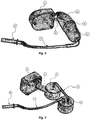
- the fluid-conducting pipe of the present invention is preferably applicable to a discharge system of a reciprocating compressor (1) comprising a first piping portion (3), a first expansion chamber (4), a second piping portion (5), and a second expansion chamber (6).
- Said first piping portion (3) connects a discharge chamber (2) of the compressor (1) to the first expansion chamber 4.
- the second piping portion (5) connects the first expansion chamber (4) to the second expansion chamber (6).
- the discharge pipe (7) of the compressor connects the second expansion chamber (6) to an outlet pipe (8) of the compressor (1).
- the discharge system comprises two expansion chambers.
- the system may comprise only one expansion chamber or more than two expansion chambers.
- the discharge chamber of the compressor (1) although contributing to the attenuation of dynamic pressures (pulsations), it plays a key role in the energy efficiency performance of the compressor.
- the piping portions and the expansion chambers are sized to attenuate the dynamic pressures deriving from the pumping of refrigerant gas in the compressor.
- the structure of these components can be rigid or flexible as long as it meets the requirements of mechanical strength.
- the discharge pipe and the outlet pipe of the compressor are sequentially connected in the last expansion chamber, and they have the function of conducting the compressed refrigerant gas out of the compressor.
- the structure of such pipes is preferentially and relatively flexible to impart little vibrational energy from the inner mechanical assembly to the casing during the refrigerant gas compression process.
- the fluid-conducting pipe preferably acts as a discharge pipe (7), made of polymeric material.
- the piping made of polymeric material has lower stiffness and density, which implies a lower capacity to amplify the vibrational mechanical energy generated by the gas compression process at high angular speed of the compressor (1).
- polymeric materials have higher damping compared to metallic materials traditionally used in the state of the art.
- the discharge pipe (7) made of polymeric material does not present thermoforming.
- the pipe may be composed of polymeric materials, preferably Perfluoroalkoxy Alkane (PFA) and Fluorinated Ethylene and Propylene (FEP).
- PFA Perfluoroalkoxy Alkane
- FEP Fluorinated Ethylene and Propylene
- the discharge pipe (7) made of polymeric material comprises at least one vibrational energy dissipation element (9) disposed on its outer surface.
- vibrational energy dissipation element (9) generates friction during vibration of the discharge pipe. This friction dissipation effect is potentiated when the radial clearances between the pipe and the spring exist and are not large. When these clearances do not exist, the dissipation is minimized; on the other hand, when the radial clearances are very large, an effect of mechanical beats is generated, which may generate unwanted noise.
- said vibrational energy dissipation element (9) is a spring arranged around said discharge pipe (7) made of polymeric material, which is more susceptible to shape variation caused by various effects, such as, alteration of the mechanical properties arising from the high temperature and aging of the polymeric material and pipe manufacturing tolerances. Therefore, the use of the polymeric pipe with the spring can generate the drawback of the greater variability of the radial clearances compared to the metallic pipes with springs.
- such a spring assumes irregularly arranged spires, as shown in Figures 6 and 7 , and it may also have regularly arranged spires, as shown in Figure 5 .
- said dissipation element has a spiral geometry with constant spire diameter along its entire length.
- the constituent material of this element is preferably metallic, and it may alternatively be of polymeric material.
- the vibrational energy dissipation element has a spiral geometry with constant spire diameter; however, the periodic segments of uniform or variable lengths have each segment section misaligned relative to each other along its length.
- the spire diameters are variable along each segment, which may have uniform or non-uniform lengths. At the end of each segment, there are few spires with smaller diameters with the function of keeping the entire structure of the spring fixed in the pipe, while the other spires have larger spire diameter and may exhibit movement relative to the pipe to generate friction.
- the construction proposed in the present invention is capable of reducing noises generated by reciprocating compressors operating at a high angular speed regime, more efficiently than the solutions described in the state of the art.
Landscapes
- Engineering & Computer Science (AREA)
- General Engineering & Computer Science (AREA)
- Mechanical Engineering (AREA)
- Compressor (AREA)
- Compressors, Vaccum Pumps And Other Relevant Systems (AREA)
Abstract

Description
- The present invention refers to a fluid-conducting pipe of a reciprocating compressor discharge system. Said pipe is configured so as to reduce the noise generated in high angular speed reciprocating compressors.
- As is well known in the state of the art, reciprocating compressors of refrigeration apparatus comprise refrigerant discharge systems, which usually include acoustic filters consisting of expansion chambers and interconnecting pipes, in addition to an outlet piping of the compressor.
- It is also well known that reciprocating compressors operate at different angular speeds, depending on the volume of the compartment to be cooled, and the required cooling temperature, for example.
- For reciprocating compressors operating at high angular speed, the operating frequency of the compressor itself may coincide with the natural frequency of its discharge piping. This coincidence, or resonance, causes amplification of the vibrational energy in the discharge piping, generating high noise level in the compressor and/or breakage of the pipe by fatigue.
- In order to mitigate the generated noise, several solutions have been proposed in the state of the art. In some solutions, the maximum angular speed of the compressor is limited to values around 4500 rpm, which is equivalent to an operating frequency of 75 Hz, to avoid coincidence between the operating frequency and the first natural frequency of the discharge piping, which is around 85 Hz. However, some embodiments require higher angular speeds of operation of the reciprocating compressor.
- Alternatively, other solutions of the state of the art propose that the natural frequencies of the discharge piping and the surroundings of such frequencies be avoided, particularly with the use of angular speed control via electronic logic. However, this solution option penalizes the performance of the compressor, since it limits the angular speeds of operation.
- Furthermore, as an additional alternative, there is proposed in the state of the art the increase of the natural frequencies of the discharge piping, which implies in increasing the dynamic stiffness of the piping. Indirectly, this increases the vibration at low frequencies.
- Alternative solution is proposed by document
WO 2005/106250 A1 AT010136U1 - It is based on this scenario that the present invention arises.
- Therefore, the present invention is basically aimed at solving the problem of noise and the breakage of the pipe deriving from the resonance of the discharge piping in reciprocating compressors operating at high angular speed regimes.
- It is also another object of the present invention to provide a reciprocating compressor discharge system that is economically feasible, and technically efficient in reducing the generated noise.
- All objects of the present invention are achieved by means of a fluid-conducting pipe of a reciprocating compressor, made of polymeric material, and further comprising at least one vibrational energy dissipation element.
- In a preferred embodiment, said vibrational energy dissipation element is a spring.
- In another preferred embodiment, said vibrational energy dissipation element has geometry: spiral with constant spire diameter and periodic segments of uniform or variable lengths with each segment section being misaligned relative to each other; or spiral with variable spire diameter along each segment; or spiral with constant spire diameter along its length.
- In another preferred embodiment, said fluid-conducting pipe has the function of a discharge pipe of said reciprocating compressor.
- In another preferred embodiment, said fluid-conducting pipe is made of polymeric material without thermoforming.
- In another preferred embodiment, said polymeric material is selected from: Perfluoroalkoxy Alkane (PFA) and Fluorinated Ethylene and Propylene (FEP).
- In another preferred embodiment, said reciprocating compressor comprises at least one expansion chamber.
- The preferred embodiment of the present invention is described in detail based on the listed figures, which have a merely exemplifying and nonlimiting character, since adaptations and modifications may be made without thereby departing from the scope of the claimed protection.
-
Figure 1 refers to a graph that demonstrates the increase of noise in reciprocating compressors at angular speeds above 4,500 rpm. -
Figures 2 to 4 refer to a schematic view of the discharge system of a reciprocating compressor comprising the fluid-conducting pipe of the present invention with two expansion chambers. -
Figure 5 refers to a first embodiment of the fluid-conducting pipe provided with a vibrational energy dissipation element. -
Figure 6 refers to a second embodiment of the fluid-conducting pipe provided with a vibrational energy dissipation element. -
Figure 7 refers to a third embodiment of the fluid-conducting pipe provided with a vibrational energy dissipation element. - As shown in the figures, the present invention refers to a fluid-conducting pipe provided with a specific construction, which allows to solve the problem of noise and/or breakage of the pipe deriving from the resonance of the discharge piping in reciprocating compressors operating at high angular speed regimes (above 4,500 rpm), economically feasible, and technically efficient.
- As shown in
Figure 1 , the peak of noise level generated by reciprocating compressors is characterized precisely at rotations above 4,500 rpm, so that constructions directed for this problem are highly necessary. - Thus, the fluid-conducting pipe of the present invention is preferably applicable to a discharge system of a reciprocating compressor (1) comprising a first piping portion (3), a first expansion chamber (4), a second piping portion (5), and a second expansion chamber (6). Said first piping portion (3) connects a discharge chamber (2) of the compressor (1) to the
first expansion chamber 4. The second piping portion (5) connects the first expansion chamber (4) to the second expansion chamber (6). The discharge pipe (7) of the compressor connects the second expansion chamber (6) to an outlet pipe (8) of the compressor (1). - Preferably, the discharge system comprises two expansion chambers. Alternatively, the system may comprise only one expansion chamber or more than two expansion chambers.
- The discharge chamber of the compressor (1), although contributing to the attenuation of dynamic pressures (pulsations), it plays a key role in the energy efficiency performance of the compressor. The piping portions and the expansion chambers are sized to attenuate the dynamic pressures deriving from the pumping of refrigerant gas in the compressor. The structure of these components can be rigid or flexible as long as it meets the requirements of mechanical strength. The discharge pipe and the outlet pipe of the compressor are sequentially connected in the last expansion chamber, and they have the function of conducting the compressed refrigerant gas out of the compressor.
- The structure of such pipes is preferentially and relatively flexible to impart little vibrational energy from the inner mechanical assembly to the casing during the refrigerant gas compression process.
- According to the present invention, the fluid-conducting pipe preferably acts as a discharge pipe (7), made of polymeric material. The piping made of polymeric material has lower stiffness and density, which implies a lower capacity to amplify the vibrational mechanical energy generated by the gas compression process at high angular speed of the compressor (1).
- In addition, polymeric materials have higher damping compared to metallic materials traditionally used in the state of the art.
- Preferably, the discharge pipe (7) made of polymeric material does not present thermoforming.
- The pipe may be composed of polymeric materials, preferably Perfluoroalkoxy Alkane (PFA) and Fluorinated Ethylene and Propylene (FEP).
- Furthermore, according to the present invention, the discharge pipe (7) made of polymeric material comprises at least one vibrational energy dissipation element (9) disposed on its outer surface.
- This is necessary because the noise reduction produced by the discharge pipe in polymeric material is not sufficient as an attenuator for situations of reciprocating compressors operating at higher rotation regimes.
- The use of the vibrational energy dissipation element (9) generates friction during vibration of the discharge pipe. This friction dissipation effect is potentiated when the radial clearances between the pipe and the spring exist and are not large. When these clearances do not exist, the dissipation is minimized; on the other hand, when the radial clearances are very large, an effect of mechanical beats is generated, which may generate unwanted noise.
- Preferably, said vibrational energy dissipation element (9) is a spring arranged around said discharge pipe (7) made of polymeric material, which is more susceptible to shape variation caused by various effects, such as, alteration of the mechanical properties arising from the high temperature and aging of the polymeric material and pipe manufacturing tolerances. Therefore, the use of the polymeric pipe with the spring can generate the drawback of the greater variability of the radial clearances compared to the metallic pipes with springs.
- In the context of such problems of radial clearances, in a preferred embodiment, such a spring assumes irregularly arranged spires, as shown in
Figures 6 and 7 , and it may also have regularly arranged spires, as shown inFigure 5 . - In the construction of
Figure 5 , said dissipation element has a spiral geometry with constant spire diameter along its entire length. The constituent material of this element is preferably metallic, and it may alternatively be of polymeric material. - The possibility of irregular arrangement of the spires enables the radial clearances between the spring and the pipe to be adaptively controlled, since these clearances are influential in the dissipation of the vibrational energy.
- In the construction of
Figures 6 , the vibrational energy dissipation element has a spiral geometry with constant spire diameter; however, the periodic segments of uniform or variable lengths have each segment section misaligned relative to each other along its length. - In the construction of
Figure 7 , the spire diameters are variable along each segment, which may have uniform or non-uniform lengths. At the end of each segment, there are few spires with smaller diameters with the function of keeping the entire structure of the spring fixed in the pipe, while the other spires have larger spire diameter and may exhibit movement relative to the pipe to generate friction. - Accordingly, the construction proposed in the present invention is capable of reducing noises generated by reciprocating compressors operating at a high angular speed regime, more efficiently than the solutions described in the state of the art.
- It is important to emphasize that the above description has the sole purpose of describing, in an exemplary manner, the particular embodiment of the present invention. Therefore, it is clear that modifications, variations and constructive combinations of the elements performing the same function substantially in the same manner to achieve the same results, remain within the scope of protection defined by the appended claims.
Claims (7)
- Fluid-conducting pipe of a reciprocating compressor (1), characterized by the fact that it is made of polymeric material, and further comprises at least one vibrational energy dissipation element (9).
- Fluid-conducting pipe according to claim 1, characterized by the fact that said vibrational energy dissipation element (9) is a spring.
- Fluid-conducting pipe according to claim 2, characterized by the fact that said vibrational energy dissipation element (9) has geometry:- spiral with constant spire diameter and periodic segments of uniform or variable lengths with each segment section being misaligned relative to each other; or- spiral with variable spire diameter along each segment with uniform or variable lengths; or- spiral with constant spire diameter along its length.
- Fluid-conducting pipe according to any one of claims 1 to 3, characterized by the fact that said fluid-conducting pipe has the function of a discharge pipe (7) of said reciprocating compressor (1).
- Fluid-conducting pipe according to any one of claims 1 to 4, characterized by the fact that said fluid-conducting pipe is made of polymeric material without thermoforming.
- Fluid-conducting pipe according to any one of claims 1 to 5, characterized by the fact that the polymeric material is selected from: Perfluoroalkoxy Alkane (PFA) and Fluorinated Ethylene and Propylene (FEP).
- Fluid-conducting pipe according to any one of claims 1 to 6, characterized by the fact that said reciprocating compressor (1) comprises at least one expansion chamber.
Applications Claiming Priority (1)
| Application Number | Priority Date | Filing Date | Title |
|---|---|---|---|
| BR102018015458-3A BR102018015458B1 (en) | 2018-07-27 | 2018-07-27 | FLUID CONDUCTOR TUBE |
Publications (2)
| Publication Number | Publication Date |
|---|---|
| EP3599378A1 true EP3599378A1 (en) | 2020-01-29 |
| EP3599378B1 EP3599378B1 (en) | 2021-05-19 |
Family
ID=67438742
Family Applications (1)
| Application Number | Title | Priority Date | Filing Date |
|---|---|---|---|
| EP19188134.1A Active EP3599378B1 (en) | 2018-07-27 | 2019-07-24 | Fluid-conducting pipe |
Country Status (6)
| Country | Link |
|---|---|
| US (1) | US20200032944A1 (en) |
| EP (1) | EP3599378B1 (en) |
| JP (1) | JP2020016235A (en) |
| CN (1) | CN110778484B (en) |
| BR (1) | BR102018015458B1 (en) |
| ES (1) | ES2883804T3 (en) |
Cited By (1)
| Publication number | Priority date | Publication date | Assignee | Title |
|---|---|---|---|---|
| EP4293226A1 (en) * | 2022-06-16 | 2023-12-20 | LG Electronics Inc. | Reciprocating compressor |
Families Citing this family (1)
| Publication number | Priority date | Publication date | Assignee | Title |
|---|---|---|---|---|
| KR20250080621A (en) * | 2023-11-28 | 2025-06-05 | 엘지전자 주식회사 | Compressor |
Citations (7)
| Publication number | Priority date | Publication date | Assignee | Title |
|---|---|---|---|---|
| FR2571814A1 (en) * | 1984-10-15 | 1986-04-18 | Euroflex | Flexible hose for conveying fluid |
| WO1997031188A1 (en) * | 1996-02-20 | 1997-08-28 | Matsushita Refrigeration Company | Inverter-controlled sealed compressor |
| US20020009370A1 (en) * | 2000-06-13 | 2002-01-24 | Kueon Young-Su | Exhausting spring structure for high-pressure discharging pipe of compressor |
| US20020127123A1 (en) * | 2001-03-12 | 2002-09-12 | Sung-Tae Lee | Compressor |
| WO2005106250A1 (en) | 2004-04-28 | 2005-11-10 | Acc Austria Gmbh | Refrigerant compressor |
| US20060093497A1 (en) * | 2004-11-02 | 2006-05-04 | Lg Electronics Inc. | Compressor |
| AT10136U1 (en) | 2007-10-05 | 2008-09-15 | Acc Austria Gmbh | REFRIGERANT COMPRESSOR |
Family Cites Families (15)
| Publication number | Priority date | Publication date | Assignee | Title |
|---|---|---|---|---|
| JPH09137779A (en) * | 1995-11-16 | 1997-05-27 | Sanyo Electric Co Ltd | Refrigerant compressor |
| DE19547565C1 (en) * | 1995-12-20 | 1997-04-30 | Richard Norres | Tube or ducting with sound attenuation used in e.g. gas turbine applications |
| JP2001012602A (en) * | 1999-06-25 | 2001-01-16 | Sony Corp | Coil spring |
| US7055812B2 (en) * | 2002-09-30 | 2006-06-06 | Bal Seal Engineering Co., Inc. | Canted coil springs various designs |
| KR100564439B1 (en) * | 2003-11-14 | 2006-03-29 | 엘지전자 주식회사 | Hermetic Compressor |
| DE10354782B3 (en) * | 2003-11-21 | 2005-07-14 | Westfalia Metallschlauchtechnik Gmbh & Co. Kg | Torsional decoupling element for pipelines subject to vibration has bellows-type components offset axially to pipe axis of adjacent line system |
| CN1782372A (en) * | 2004-11-29 | 2006-06-07 | 乐金电子(天津)电器有限公司 | Vibration reducing device for reciprocating compressor |
| CN1782373A (en) * | 2004-11-29 | 2006-06-07 | 乐金电子(天津)电器有限公司 | Vibrative noise reducing device for reciprocating compressor |
| BRPI0613759A2 (en) * | 2005-07-22 | 2011-02-08 | Fisher & Paykel Appliances Ltd | flexible discharge duct refrigeration compressor |
| ATE543712T1 (en) * | 2009-03-20 | 2012-02-15 | Voith Patent Gmbh | ENERGY ABSORPTION ELEMENT AND SHOCK PROTECTION WITH AN ENERGY ABSORPTION ELEMENT |
| KR101299553B1 (en) * | 2011-09-06 | 2013-08-23 | 엘지전자 주식회사 | Reciprocating compressor with gas bearing |
| BRPI1105017B1 (en) * | 2011-11-25 | 2020-06-16 | Embraco Indústria De Compressores E Soluções E Refrigeração Ltda. | RESONANT SPRING DEFORMATION CONTROL DEVICE IN A LINEAR ACTUATION UNIT |
| BR102012026728A2 (en) * | 2012-10-18 | 2014-08-26 | Whirlpool Sa | EXPANSION CHAMBER FOR ALTERNATIVE COMPRESSOR UNLOADING LINE |
| CN105298798A (en) * | 2014-07-15 | 2016-02-03 | 珠海格力节能环保制冷技术研究中心有限公司 | Reciprocating linear compressor and inner exhaust tube set thereof |
| CN205990998U (en) * | 2016-06-14 | 2017-03-01 | 惠而浦股份有限公司 | It is introduced into the constructional device in the gas extraction system of reciprocating compressor |
-
2018
- 2018-07-27 BR BR102018015458-3A patent/BR102018015458B1/en active IP Right Grant
-
2019
- 2019-07-17 JP JP2019131643A patent/JP2020016235A/en active Pending
- 2019-07-18 US US16/515,189 patent/US20200032944A1/en not_active Abandoned
- 2019-07-24 EP EP19188134.1A patent/EP3599378B1/en active Active
- 2019-07-24 ES ES19188134T patent/ES2883804T3/en active Active
- 2019-07-26 CN CN201910679340.4A patent/CN110778484B/en active Active
Patent Citations (7)
| Publication number | Priority date | Publication date | Assignee | Title |
|---|---|---|---|---|
| FR2571814A1 (en) * | 1984-10-15 | 1986-04-18 | Euroflex | Flexible hose for conveying fluid |
| WO1997031188A1 (en) * | 1996-02-20 | 1997-08-28 | Matsushita Refrigeration Company | Inverter-controlled sealed compressor |
| US20020009370A1 (en) * | 2000-06-13 | 2002-01-24 | Kueon Young-Su | Exhausting spring structure for high-pressure discharging pipe of compressor |
| US20020127123A1 (en) * | 2001-03-12 | 2002-09-12 | Sung-Tae Lee | Compressor |
| WO2005106250A1 (en) | 2004-04-28 | 2005-11-10 | Acc Austria Gmbh | Refrigerant compressor |
| US20060093497A1 (en) * | 2004-11-02 | 2006-05-04 | Lg Electronics Inc. | Compressor |
| AT10136U1 (en) | 2007-10-05 | 2008-09-15 | Acc Austria Gmbh | REFRIGERANT COMPRESSOR |
Cited By (2)
| Publication number | Priority date | Publication date | Assignee | Title |
|---|---|---|---|---|
| EP4293226A1 (en) * | 2022-06-16 | 2023-12-20 | LG Electronics Inc. | Reciprocating compressor |
| US12338807B2 (en) | 2022-06-16 | 2025-06-24 | Lg Electronics Inc. | Reciprocating compressor |
Also Published As
| Publication number | Publication date |
|---|---|
| US20200032944A1 (en) | 2020-01-30 |
| ES2883804T3 (en) | 2021-12-09 |
| JP2020016235A (en) | 2020-01-30 |
| CN110778484B (en) | 2023-06-23 |
| CN110778484A (en) | 2020-02-11 |
| BR102018015458B1 (en) | 2021-12-21 |
| BR102018015458A2 (en) | 2020-02-11 |
| EP3599378B1 (en) | 2021-05-19 |
Similar Documents
| Publication | Publication Date | Title |
|---|---|---|
| CN105317660B (en) | The manufacturing method of Linearkompressor, the housing of Linearkompressor and the housing | |
| US9714648B2 (en) | Linear compressor | |
| EP3599378B1 (en) | Fluid-conducting pipe | |
| US6935848B2 (en) | Discharge muffler placement in a compressor | |
| JP5866004B2 (en) | Hermetic compressor and heat pump device | |
| WO2007124552A1 (en) | Resonator arrangement in an acoustic muffler for a refrigeration compressor | |
| JP2004218934A (en) | Expansion type muffler, refrigeration cycle circuit using the same, and method of manufacturing the same | |
| US9353773B2 (en) | Mounting arrangement for a suction muffler in a linear motor compressor | |
| US11536501B2 (en) | Oil separator with integrated muffler | |
| CN106662090A (en) | Hermetic compressor and refrigeration device | |
| US7494328B2 (en) | NVH and gas pulsation reduction in AC compressor | |
| US7585161B2 (en) | Compressor | |
| WO2008098330A2 (en) | Constructive arrangement of an acoustic filter for a refrigeration compressor | |
| WO2014057602A1 (en) | Compressor | |
| EP2580475B1 (en) | A hermetic compressor | |
| JP2020193576A (en) | Scroll compressor and refrigerator with the same | |
| KR100527587B1 (en) | Noise reducing structure of reciprocating compressor | |
| US20040213682A1 (en) | Hermetic compressor | |
| CN114017336B (en) | Compressor and Refrigeration Equipment | |
| KR102734939B1 (en) | Rear head of swash plate compressor | |
| JP7833049B2 (en) | Compressor device and compressor assembly comprising such compressor device | |
| WO2025082964A1 (en) | A scroll compressor having a middle shell with a barrel-shaped section | |
| EP4602308A1 (en) | Heat pump comprising a vibration influencer | |
| CN106489025B (en) | Compressor with a compressor housing having a plurality of compressor blades | |
| CN114017342A (en) | Compressor and refrigeration equipment thereof |
Legal Events
| Date | Code | Title | Description |
|---|---|---|---|
| PUAI | Public reference made under article 153(3) epc to a published international application that has entered the european phase |
Free format text: ORIGINAL CODE: 0009012 |
|
| STAA | Information on the status of an ep patent application or granted ep patent |
Free format text: STATUS: THE APPLICATION HAS BEEN PUBLISHED |
|
| AK | Designated contracting states |
Kind code of ref document: A1 Designated state(s): AL AT BE BG CH CY CZ DE DK EE ES FI FR GB GR HR HU IE IS IT LI LT LU LV MC MK MT NL NO PL PT RO RS SE SI SK SM TR |
|
| AX | Request for extension of the european patent |
Extension state: BA ME |
|
| STAA | Information on the status of an ep patent application or granted ep patent |
Free format text: STATUS: REQUEST FOR EXAMINATION WAS MADE |
|
| 17P | Request for examination filed |
Effective date: 20200729 |
|
| RBV | Designated contracting states (corrected) |
Designated state(s): AL AT BE BG CH CY CZ DE DK EE ES FI FR GB GR HR HU IE IS IT LI LT LU LV MC MK MT NL NO PL PT RO RS SE SI SK SM TR |
|
| GRAP | Despatch of communication of intention to grant a patent |
Free format text: ORIGINAL CODE: EPIDOSNIGR1 |
|
| STAA | Information on the status of an ep patent application or granted ep patent |
Free format text: STATUS: GRANT OF PATENT IS INTENDED |
|
| INTG | Intention to grant announced |
Effective date: 20201208 |
|
| GRAS | Grant fee paid |
Free format text: ORIGINAL CODE: EPIDOSNIGR3 |
|
| GRAA | (expected) grant |
Free format text: ORIGINAL CODE: 0009210 |
|
| STAA | Information on the status of an ep patent application or granted ep patent |
Free format text: STATUS: THE PATENT HAS BEEN GRANTED |
|
| AK | Designated contracting states |
Kind code of ref document: B1 Designated state(s): AL AT BE BG CH CY CZ DE DK EE ES FI FR GB GR HR HU IE IS IT LI LT LU LV MC MK MT NL NO PL PT RO RS SE SI SK SM TR |
|
| REG | Reference to a national code |
Ref country code: GB Ref legal event code: FG4D |
|
| REG | Reference to a national code |
Ref country code: CH Ref legal event code: EP |
|
| REG | Reference to a national code |
Ref country code: DE Ref legal event code: R096 Ref document number: 602019004678 Country of ref document: DE |
|
| REG | Reference to a national code |
Ref country code: AT Ref legal event code: REF Ref document number: 1394228 Country of ref document: AT Kind code of ref document: T Effective date: 20210615 |
|
| REG | Reference to a national code |
Ref country code: IE Ref legal event code: FG4D |
|
| REG | Reference to a national code |
Ref country code: LT Ref legal event code: MG9D |
|
| REG | Reference to a national code |
Ref country code: NL Ref legal event code: MP Effective date: 20210519 Ref country code: SK Ref legal event code: T3 Ref document number: E 38099 Country of ref document: SK |
|
| PG25 | Lapsed in a contracting state [announced via postgrant information from national office to epo] |
Ref country code: FI Free format text: LAPSE BECAUSE OF FAILURE TO SUBMIT A TRANSLATION OF THE DESCRIPTION OR TO PAY THE FEE WITHIN THE PRESCRIBED TIME-LIMIT Effective date: 20210519 Ref country code: HR Free format text: LAPSE BECAUSE OF FAILURE TO SUBMIT A TRANSLATION OF THE DESCRIPTION OR TO PAY THE FEE WITHIN THE PRESCRIBED TIME-LIMIT Effective date: 20210519 Ref country code: LT Free format text: LAPSE BECAUSE OF FAILURE TO SUBMIT A TRANSLATION OF THE DESCRIPTION OR TO PAY THE FEE WITHIN THE PRESCRIBED TIME-LIMIT Effective date: 20210519 Ref country code: BG Free format text: LAPSE BECAUSE OF FAILURE TO SUBMIT A TRANSLATION OF THE DESCRIPTION OR TO PAY THE FEE WITHIN THE PRESCRIBED TIME-LIMIT Effective date: 20210819 |
|
| PG25 | Lapsed in a contracting state [announced via postgrant information from national office to epo] |
Ref country code: PT Free format text: LAPSE BECAUSE OF FAILURE TO SUBMIT A TRANSLATION OF THE DESCRIPTION OR TO PAY THE FEE WITHIN THE PRESCRIBED TIME-LIMIT Effective date: 20210920 Ref country code: RS Free format text: LAPSE BECAUSE OF FAILURE TO SUBMIT A TRANSLATION OF THE DESCRIPTION OR TO PAY THE FEE WITHIN THE PRESCRIBED TIME-LIMIT Effective date: 20210519 Ref country code: SE Free format text: LAPSE BECAUSE OF FAILURE TO SUBMIT A TRANSLATION OF THE DESCRIPTION OR TO PAY THE FEE WITHIN THE PRESCRIBED TIME-LIMIT Effective date: 20210519 Ref country code: PL Free format text: LAPSE BECAUSE OF FAILURE TO SUBMIT A TRANSLATION OF THE DESCRIPTION OR TO PAY THE FEE WITHIN THE PRESCRIBED TIME-LIMIT Effective date: 20210519 Ref country code: NO Free format text: LAPSE BECAUSE OF FAILURE TO SUBMIT A TRANSLATION OF THE DESCRIPTION OR TO PAY THE FEE WITHIN THE PRESCRIBED TIME-LIMIT Effective date: 20210819 Ref country code: LV Free format text: LAPSE BECAUSE OF FAILURE TO SUBMIT A TRANSLATION OF THE DESCRIPTION OR TO PAY THE FEE WITHIN THE PRESCRIBED TIME-LIMIT Effective date: 20210519 Ref country code: IS Free format text: LAPSE BECAUSE OF FAILURE TO SUBMIT A TRANSLATION OF THE DESCRIPTION OR TO PAY THE FEE WITHIN THE PRESCRIBED TIME-LIMIT Effective date: 20210919 |
|
| REG | Reference to a national code |
Ref country code: ES Ref legal event code: FG2A Ref document number: 2883804 Country of ref document: ES Kind code of ref document: T3 Effective date: 20211209 |
|
| PG25 | Lapsed in a contracting state [announced via postgrant information from national office to epo] |
Ref country code: NL Free format text: LAPSE BECAUSE OF FAILURE TO SUBMIT A TRANSLATION OF THE DESCRIPTION OR TO PAY THE FEE WITHIN THE PRESCRIBED TIME-LIMIT Effective date: 20210519 |
|
| PG25 | Lapsed in a contracting state [announced via postgrant information from national office to epo] |
Ref country code: SM Free format text: LAPSE BECAUSE OF FAILURE TO SUBMIT A TRANSLATION OF THE DESCRIPTION OR TO PAY THE FEE WITHIN THE PRESCRIBED TIME-LIMIT Effective date: 20210519 Ref country code: RO Free format text: LAPSE BECAUSE OF FAILURE TO SUBMIT A TRANSLATION OF THE DESCRIPTION OR TO PAY THE FEE WITHIN THE PRESCRIBED TIME-LIMIT Effective date: 20210519 Ref country code: CZ Free format text: LAPSE BECAUSE OF FAILURE TO SUBMIT A TRANSLATION OF THE DESCRIPTION OR TO PAY THE FEE WITHIN THE PRESCRIBED TIME-LIMIT Effective date: 20210519 Ref country code: DK Free format text: LAPSE BECAUSE OF FAILURE TO SUBMIT A TRANSLATION OF THE DESCRIPTION OR TO PAY THE FEE WITHIN THE PRESCRIBED TIME-LIMIT Effective date: 20210519 Ref country code: EE Free format text: LAPSE BECAUSE OF FAILURE TO SUBMIT A TRANSLATION OF THE DESCRIPTION OR TO PAY THE FEE WITHIN THE PRESCRIBED TIME-LIMIT Effective date: 20210519 |
|
| REG | Reference to a national code |
Ref country code: DE Ref legal event code: R097 Ref document number: 602019004678 Country of ref document: DE |
|
| PLBE | No opposition filed within time limit |
Free format text: ORIGINAL CODE: 0009261 |
|
| STAA | Information on the status of an ep patent application or granted ep patent |
Free format text: STATUS: NO OPPOSITION FILED WITHIN TIME LIMIT |
|
| PG25 | Lapsed in a contracting state [announced via postgrant information from national office to epo] |
Ref country code: MC Free format text: LAPSE BECAUSE OF FAILURE TO SUBMIT A TRANSLATION OF THE DESCRIPTION OR TO PAY THE FEE WITHIN THE PRESCRIBED TIME-LIMIT Effective date: 20210519 |
|
| REG | Reference to a national code |
Ref country code: BE Ref legal event code: MM Effective date: 20210731 |
|
| 26N | No opposition filed |
Effective date: 20220222 |
|
| PG25 | Lapsed in a contracting state [announced via postgrant information from national office to epo] |
Ref country code: IS Free format text: LAPSE BECAUSE OF FAILURE TO SUBMIT A TRANSLATION OF THE DESCRIPTION OR TO PAY THE FEE WITHIN THE PRESCRIBED TIME-LIMIT Effective date: 20210919 Ref country code: LU Free format text: LAPSE BECAUSE OF NON-PAYMENT OF DUE FEES Effective date: 20210724 Ref country code: FR Free format text: LAPSE BECAUSE OF NON-PAYMENT OF DUE FEES Effective date: 20210731 Ref country code: AL Free format text: LAPSE BECAUSE OF FAILURE TO SUBMIT A TRANSLATION OF THE DESCRIPTION OR TO PAY THE FEE WITHIN THE PRESCRIBED TIME-LIMIT Effective date: 20210519 |
|
| REG | Reference to a national code |
Ref country code: DE Ref legal event code: R082 Ref document number: 602019004678 Country of ref document: DE Representative=s name: SCHIEBER - FARAGO PATENTANWAELTE, DE Ref country code: DE Ref legal event code: R082 Ref document number: 602019004678 Country of ref document: DE Representative=s name: FARAGO PATENTANWALTSGESELLSCHAFT MBH, DE |
|
| PG25 | Lapsed in a contracting state [announced via postgrant information from national office to epo] |
Ref country code: IE Free format text: LAPSE BECAUSE OF NON-PAYMENT OF DUE FEES Effective date: 20210724 Ref country code: BE Free format text: LAPSE BECAUSE OF NON-PAYMENT OF DUE FEES Effective date: 20210731 |
|
| REG | Reference to a national code |
Ref country code: DE Ref legal event code: R082 Ref document number: 602019004678 Country of ref document: DE Representative=s name: SCHIEBER - FARAGO PATENTANWAELTE, DE |
|
| PGFP | Annual fee paid to national office [announced via postgrant information from national office to epo] |
Ref country code: IT Payment date: 20220801 Year of fee payment: 4 Ref country code: ES Payment date: 20220928 Year of fee payment: 4 |
|
| REG | Reference to a national code |
Ref country code: CH Ref legal event code: PL |
|
| PG25 | Lapsed in a contracting state [announced via postgrant information from national office to epo] |
Ref country code: LI Free format text: LAPSE BECAUSE OF NON-PAYMENT OF DUE FEES Effective date: 20220731 Ref country code: CH Free format text: LAPSE BECAUSE OF NON-PAYMENT OF DUE FEES Effective date: 20220731 |
|
| PG25 | Lapsed in a contracting state [announced via postgrant information from national office to epo] |
Ref country code: CY Free format text: LAPSE BECAUSE OF FAILURE TO SUBMIT A TRANSLATION OF THE DESCRIPTION OR TO PAY THE FEE WITHIN THE PRESCRIBED TIME-LIMIT Effective date: 20210519 |
|
| PG25 | Lapsed in a contracting state [announced via postgrant information from national office to epo] |
Ref country code: HU Free format text: LAPSE BECAUSE OF FAILURE TO SUBMIT A TRANSLATION OF THE DESCRIPTION OR TO PAY THE FEE WITHIN THE PRESCRIBED TIME-LIMIT; INVALID AB INITIO Effective date: 20190724 Ref country code: GR Free format text: LAPSE BECAUSE OF FAILURE TO SUBMIT A TRANSLATION OF THE DESCRIPTION OR TO PAY THE FEE WITHIN THE PRESCRIBED TIME-LIMIT Effective date: 20210519 |
|
| GBPC | Gb: european patent ceased through non-payment of renewal fee |
Effective date: 20230724 |
|
| PG25 | Lapsed in a contracting state [announced via postgrant information from national office to epo] |
Ref country code: MK Free format text: LAPSE BECAUSE OF FAILURE TO SUBMIT A TRANSLATION OF THE DESCRIPTION OR TO PAY THE FEE WITHIN THE PRESCRIBED TIME-LIMIT Effective date: 20210519 Ref country code: GB Free format text: LAPSE BECAUSE OF NON-PAYMENT OF DUE FEES Effective date: 20230724 |
|
| PG25 | Lapsed in a contracting state [announced via postgrant information from national office to epo] |
Ref country code: IT Free format text: LAPSE BECAUSE OF NON-PAYMENT OF DUE FEES Effective date: 20230724 |
|
| REG | Reference to a national code |
Ref country code: ES Ref legal event code: FD2A Effective date: 20240827 |
|
| PG25 | Lapsed in a contracting state [announced via postgrant information from national office to epo] |
Ref country code: MT Free format text: LAPSE BECAUSE OF FAILURE TO SUBMIT A TRANSLATION OF THE DESCRIPTION OR TO PAY THE FEE WITHIN THE PRESCRIBED TIME-LIMIT Effective date: 20210519 |
|
| PG25 | Lapsed in a contracting state [announced via postgrant information from national office to epo] |
Ref country code: ES Free format text: LAPSE BECAUSE OF NON-PAYMENT OF DUE FEES Effective date: 20230725 |
|
| PG25 | Lapsed in a contracting state [announced via postgrant information from national office to epo] |
Ref country code: ES Free format text: LAPSE BECAUSE OF NON-PAYMENT OF DUE FEES Effective date: 20230725 |
|
| PGFP | Annual fee paid to national office [announced via postgrant information from national office to epo] |
Ref country code: TR Payment date: 20250627 Year of fee payment: 7 |
|
| PGFP | Annual fee paid to national office [announced via postgrant information from national office to epo] |
Ref country code: DE Payment date: 20250720 Year of fee payment: 7 |
|
| PGFP | Annual fee paid to national office [announced via postgrant information from national office to epo] |
Ref country code: AT Payment date: 20250721 Year of fee payment: 7 |
|
| PGFP | Annual fee paid to national office [announced via postgrant information from national office to epo] |
Ref country code: SK Payment date: 20250709 Year of fee payment: 7 |