EP3599357A1 - Hochdruckverdichter für ein triebwerk - Google Patents
Hochdruckverdichter für ein triebwerk Download PDFInfo
- Publication number
- EP3599357A1 EP3599357A1 EP19187370.2A EP19187370A EP3599357A1 EP 3599357 A1 EP3599357 A1 EP 3599357A1 EP 19187370 A EP19187370 A EP 19187370A EP 3599357 A1 EP3599357 A1 EP 3599357A1
- Authority
- EP
- European Patent Office
- Prior art keywords
- quasi
- stator
- rotor
- stage
- pressure compressor
- Prior art date
- Legal status (The legal status is an assumption and is not a legal conclusion. Google has not performed a legal analysis and makes no representation as to the accuracy of the status listed.)
- Granted
Links
Images
Classifications
-
- F—MECHANICAL ENGINEERING; LIGHTING; HEATING; WEAPONS; BLASTING
- F04—POSITIVE - DISPLACEMENT MACHINES FOR LIQUIDS; PUMPS FOR LIQUIDS OR ELASTIC FLUIDS
- F04D—NON-POSITIVE-DISPLACEMENT PUMPS
- F04D19/00—Axial-flow pumps
- F04D19/02—Multi-stage pumps
-
- F—MECHANICAL ENGINEERING; LIGHTING; HEATING; WEAPONS; BLASTING
- F01—MACHINES OR ENGINES IN GENERAL; ENGINE PLANTS IN GENERAL; STEAM ENGINES
- F01D—NON-POSITIVE DISPLACEMENT MACHINES OR ENGINES, e.g. STEAM TURBINES
- F01D1/00—Non-positive-displacement machines or engines, e.g. steam turbines
- F01D1/02—Non-positive-displacement machines or engines, e.g. steam turbines with stationary working-fluid guiding means and bladed or like rotor, e.g. multi-bladed impulse steam turbines
- F01D1/10—Non-positive-displacement machines or engines, e.g. steam turbines with stationary working-fluid guiding means and bladed or like rotor, e.g. multi-bladed impulse steam turbines having two or more stages subjected to working-fluid flow without essential intermediate pressure change, i.e. with velocity stages
-
- F—MECHANICAL ENGINEERING; LIGHTING; HEATING; WEAPONS; BLASTING
- F02—COMBUSTION ENGINES; HOT-GAS OR COMBUSTION-PRODUCT ENGINE PLANTS
- F02C—GAS-TURBINE PLANTS; AIR INTAKES FOR JET-PROPULSION PLANTS; CONTROLLING FUEL SUPPLY IN AIR-BREATHING JET-PROPULSION PLANTS
- F02C3/00—Gas-turbine plants characterised by the use of combustion products as the working fluid
- F02C3/04—Gas-turbine plants characterised by the use of combustion products as the working fluid having a turbine driving a compressor
- F02C3/06—Gas-turbine plants characterised by the use of combustion products as the working fluid having a turbine driving a compressor the compressor comprising only axial stages
-
- F—MECHANICAL ENGINEERING; LIGHTING; HEATING; WEAPONS; BLASTING
- F04—POSITIVE - DISPLACEMENT MACHINES FOR LIQUIDS; PUMPS FOR LIQUIDS OR ELASTIC FLUIDS
- F04D—NON-POSITIVE-DISPLACEMENT PUMPS
- F04D29/00—Details, component parts, or accessories
- F04D29/18—Rotors
- F04D29/181—Axial flow rotors
-
- F—MECHANICAL ENGINEERING; LIGHTING; HEATING; WEAPONS; BLASTING
- F04—POSITIVE - DISPLACEMENT MACHINES FOR LIQUIDS; PUMPS FOR LIQUIDS OR ELASTIC FLUIDS
- F04D—NON-POSITIVE-DISPLACEMENT PUMPS
- F04D29/00—Details, component parts, or accessories
- F04D29/40—Casings; Connections of working fluid
- F04D29/52—Casings; Connections of working fluid for axial pumps
- F04D29/54—Fluid-guiding means, e.g. diffusers
- F04D29/541—Specially adapted for elastic fluid pumps
-
- F—MECHANICAL ENGINEERING; LIGHTING; HEATING; WEAPONS; BLASTING
- F05—INDEXING SCHEMES RELATING TO ENGINES OR PUMPS IN VARIOUS SUBCLASSES OF CLASSES F01-F04
- F05D—INDEXING SCHEME FOR ASPECTS RELATING TO NON-POSITIVE-DISPLACEMENT MACHINES OR ENGINES, GAS-TURBINES OR JET-PROPULSION PLANTS
- F05D2250/00—Geometry
- F05D2250/30—Arrangement of components
-
- Y—GENERAL TAGGING OF NEW TECHNOLOGICAL DEVELOPMENTS; GENERAL TAGGING OF CROSS-SECTIONAL TECHNOLOGIES SPANNING OVER SEVERAL SECTIONS OF THE IPC; TECHNICAL SUBJECTS COVERED BY FORMER USPC CROSS-REFERENCE ART COLLECTIONS [XRACs] AND DIGESTS
- Y02—TECHNOLOGIES OR APPLICATIONS FOR MITIGATION OR ADAPTATION AGAINST CLIMATE CHANGE
- Y02T—CLIMATE CHANGE MITIGATION TECHNOLOGIES RELATED TO TRANSPORTATION
- Y02T50/00—Aeronautics or air transport
- Y02T50/60—Efficient propulsion technologies, e.g. for aircraft
Definitions
- the present invention relates to a high pressure compressor for an engine.
- the engine is functionally divided into a compressor, combustion chamber and turbine. Air drawn in is compressed in the compressor and burned in the downstream combustion chamber with added kerosene. The resulting hot gas, a mixture of combustion gas and air, flows through the downstream turbine and is expanded. Energy is also partially removed from the flowing gas in order to drive the compressor or, in the case of a turbofan engine, also the fan.
- the present subject is initially directed to a module of the compressor, namely the high pressure compressor.
- the present invention is based on the technical problem of specifying a particularly advantageous high-pressure compressor for an engine.
- the blade tightness (English solidity ) is the reciprocal of the division ratio T / L (the division ratio is the ratio of the circumferential distance of the blades to the blade chord length ).
- the values of the 2nd and 3rd quasi-levels are clearly below what would initially be assumed with a view to a stable design.
- the rotor impermeability would be increased by at least 10%, and also by several percent in the case of the stators.
- the blade leak tightness of the stator of the fourth quasi-stage would be somewhat less than in the present case.
- a certain increase or shift of the blade tightness in the rear area enables the indicated reductions in the front quasi stages, whereby sufficient stability is still achieved (partial load is considered here, which is particularly critical).
- reducing the blade tightness is an advantage in terms of efficiency.
- the lower the blade tightness the smaller the wetted area, the smaller the friction losses.
- a reduction in fuel or kerosene consumption can result not only in the context of the efficiency, but also as a result of a lower weight due to the lower blade tightness.
- cost savings are also possible insofar as the lower blade tightness or number of blades also one lower number of components can mean what is particularly relevant for adjustable stators.
- At least the front steps are preferably equipped with adjustment stators.
- the quasi-stages referred to in the present case are each constructed from a stator with a rotor following in the direction of flow of the compressor gas.
- the stator of the 1st quasi-stage could be regarded as an inlet grille and the subsequent rotor-stator pairs each as a stage (the respective stator follows the rotor in the stages).
- the blade tightness of the first four quasi stages lies in the following areas: Tab. 2 1st QA stator 1.14 to 1.18, especially 1.16 rotor 1.61 to 1.65, in particular 1.63 2nd QA stator 1.24 to 1.28, especially 1.26 rotor 1.44 to 1.48, especially 1.46 3rd QA stator 1.31 to 1.35, in particular 1.33 rotor 1.27 to 1.31, especially 1.29 4. QS stator 1.46 to 1.50, especially 1.48 rotor 1.26 to 1.30, especially 1.28
- the blade tightness of the stators is not distributed equidistantly over the circumference, which can help prevent external, intermediate or self-excitation, for example.
- the following division of the blade tightness can be preferred: Tab. 3 bottom Top min Max min Max Stator (1st QA) 1.02 1.13 1.07 1.19 Stator (2nd QA) 1.19 1.37 1.08 1.26 Stator (3rd QA) 1.16 1.37 1.25 1.41 Stator (4th QA) 1.41 1.67 1.34 1.58
- the blade tightness specified in Table 1 is realized with the following blade numbers, which are each given in an interval (min / max) and with a particularly preferred value: Tab. 4 min Max prefers 1st QA stator 37 41 39 rotor 24 28 26 2nd QA stator 42 46 44 rotor 34 38 36 3rd QA stator 52 56 54 rotor 48 52 50 4. QS stator 76 80 78 rotor 52 56 54
- the present high-pressure compressor is preferably made up of eight real stages and an inlet grille.
- the latter forms the stator of the first quasi level.
- the number of blades in the 1st stage is comparatively low in relation to the 8th stage, the rotor of which can preferably have 55 blades.
- a ratio of the number of blades of the rotor of the eighth quasi stage to the number of blades of the rotor of the first quasi stage can generally be, for example, between 2 and 2.2.
- the invention also relates to a compressor with a high pressure compressor and a low pressure compressor disclosed herein.
- the high-pressure compressor is preferably constructed in eight stages, the low-pressure compressor in three stages.
- the invention also relates to an engine with a compressor or high-pressure compressor discussed here.
- a high-pressure compressor pressure ratio of the high-pressure compressor has a share of at most 40% of a total compressor pressure ratio of the entire compressor, with at most 35% or 30% being further and particularly preferred.
- Preferred lower limits can be, for example, at least 15%, 20% or 25% (increasingly preferred in the order in which they are mentioned).
- the so-called cruise condition also referred to as the Aero Design Point (ADP), is considered here.
- the high pressure compressor has a high pressure compressor pressure ratio of at least 13, preferably at least 14.
- An upper limit can be at most 16.
- the first four stages of the high pressure compressor preferably have a pressure ratio of at most 6.5, preferably at most 6.1, a possible lower limit is at least 5.
- the engine is a transmission fan engine.
- the fan can have, for example, a number of blades of at least 18 and at most 25, with around 20 blades being particularly preferred. It is preferably a two-shaft engine.
- the ratio of fan diameter to compressor length can be around 2.2 (2.2 +/- 0.1), the ratio of compressor length to compressor diameter around 2.1 (2.1 +/- 0.1).
- the fan pressure ratio is at most 1.5, preferably around 1.4.
- the fan is preferably a geared fan.
- FIG. 1 shows a turbofan engine 1 in an axial section. It is functionally divided into compressor 2, combustion chamber 3 and turbine 4.
- compressor 2 which is made up of a low-pressure compressor 2.1 and a high-pressure compressor 2.2
- intake air is compressed.
- Kerosene is then mixed in the combustion chamber 3 and this mixture is burned.
- the hot gas is expanded in the turbine 4, with energy being partially removed from the hot gas (via the movement of the rotors). This is used on the one hand to drive the rotors of the compressor 2, and on the other hand to drive the fan 5, which essentially generates the feed of the turbofan engine 1.
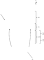
- FIG. 2 shows a part of the high pressure compressor 2.2, namely the first four quasi stages 21-24, the high pressure compressor 2.2 is constructed in eight stages.
- Each of the quasi stages 21-24 has a stator 21.1,22.1,23.1,24.1 and a downstream one Rotor 21.2,22.2,23.2,24.2 on. If one were to look at steps from the rotor and the subsequent stator as an alternative, the stator 21.1 would have to be considered as an inlet grille ( Inlet Guide Vane , IGV).
- IGV Inlet Guide Vane
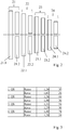
- the blade tightness or blade numbers of the quasi stages 21-24 according to Figure 2 are in Figure 3 specified (in the third column the blade tightness, in the fourth the blade number). Especially in the 2nd and 3rd quasi step 22,23, the values are significantly reduced compared to a conventional design. They are below what would normally be considered necessary for the design of a stable compressor.
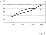
- FIG. 4 shows the blade tightness d of the stators compared to such a conventional design.
- the solid line corresponds to the design according to the invention, the dashed line to the reference design.
- the blade tightness in the fourth quasi-stage was increased somewhat.
Landscapes
- Engineering & Computer Science (AREA)
- Mechanical Engineering (AREA)
- General Engineering & Computer Science (AREA)
- Chemical & Material Sciences (AREA)
- Combustion & Propulsion (AREA)
- Physics & Mathematics (AREA)
- Fluid Mechanics (AREA)
- Structures Of Non-Positive Displacement Pumps (AREA)
Abstract
- in der ersten Quasistufe (21) für den Stator (21.1) bei mindestens 1,04 und höchstens 1,16 und für den Rotor (21.2) bei mindestens 1,46 und höchstens 1,67 liegt;
- in der zweiten Quasistufe (22) für den Stator (22.1) bei mindestens 1,13 und höchstens 1,32 und für den Rotor (22.2) bei mindestens 1,32 und höchstens 1,61 liegt;
- in der dritten Quasistufe (23) für den Stator (23.1) bei mindestens 1,20 und höchstens 1,39 und für den Rotor (23.2) bei mindestens 1,16 und höchstens 1,41 liegt;
- in der vierten Quasistufe (24) für den Stator (24.1) bei mindestens 1,37 und höchstens 1,63 und für den Rotor (24.2) bei mindestens 1,15 und höchstens 1,41 liegt.
Description
- Die vorliegende Erfindung betrifft einen Hochdruckverdichter für ein Triebwerk.
- Das Triebwerk gliedert sich funktional in Verdichter, Brennkammer und Turbine. Dabei wird angesaugte Luft im Verdichter komprimiert und in der nachgelagerten Brennkammer mit hinzugemischtem Kerosin verbrannt. Das entstehende Heißgas, eine Mischung aus Verbrennungsgas und Luft, durchströmt die nachgelagerte Turbine und wird dabei expandiert. Dem strömenden Gas wird dabei anteilig auch Energie entzogen, um den Verdichter bzw. im Falle eines Mantelstromtriebwerks auch den Fan anzutreiben. Der vorliegende Gegenstand richtet sich zunächst auf ein Modul des Verdichters, nämlich den Hochdruckverdichter.
- Der vorliegenden Erfindung liegt das technische Problem zugrunde, einen besonders vorteilhaften Hochdruckverdichter für ein Triebwerk anzugeben.
- Dies wird erfindungsgemäß mit dem Hochdruckverdichter gemäß Anspruch 1 gelöst. Dieser weist vier aufeinanderfolgende Quasistufen (QS) mit jeweils einem Stator und einem nachgelagerten Rotor auf, die sich durch folgende Schaufeldichtigkeiten im Mittelschnitt bei halber Kanalhöhe auszeichnen:
Tab. 1 min max 1. QS Stator 1,04 1,19 Rotor 1,46 1,67 2. QS Stator 1,13 1,32 Rotor 1,32 1,61 3. QS Stator 1,2 1,39 Rotor 1,16 1,41 4. QS Stator 1,37 1,63 Rotor 1,15 1,41 - Die Schaufeldichtigkeit (englisch solidity) ist der Kehrwert des Teilungsverhältnisses T/L (das Teilungsverhältnis ergibt sich als Verhältnis des Umfangsabstands der Schaufeln zur Schaufelsehnenlänge). Bei Betrachtung der vorliegend angegebenen Schaufeldichtigkeiten liegen speziell die Werte der 2. und 3. Quasistufe deutlich unter dem, was mit Blick auf eine stabile Auslegung zunächst angenommen werden würde. In einer konventionellen Herangehensweise würde man für die Rotoren dort die Schaufeldichtigkeit um mindestens 10 % höher ansiedeln, und auch im Falle der Statoren um mehrere Prozent. Umgekehrt wäre in einem solchen Referenzdesign, das sich nach konventionellen Kriterien ergeben würde, die Schaufeldichtigkeit des Stators der 4. Quasistufe etwas geringer als vorliegend. Es wurde jedoch festgestellt, dass durch eine gewisse Erhöhung bzw. Verlagerung der Schaufeldichtigkeit in den hinteren Bereich die angegebenen Absenkungen in den vorderen Quasistufen möglich werden, wobei noch immer hinreichend Stabilität erzielt wird (betrachtet wird hierbei Teillast, die besonders kritisch ist).
- Generell ist die Verringerung der Schaufeldichtigkeit hinsichtlich des Wirkungsgrads von Vorteil. Je geringer die Schaufeldichtigkeit, je geringer also die benetzte Fläche ist, desto kleiner werden auch die Reibungsverluste. Eine Verringerung des Treibstoff- bzw. Kerosinverbrauchs kann sich jedoch nicht nur im Kontext des Wirkungsgrads ergeben, sondern auch infolge eines aufgrund der geringeren Schaufeldichtigkeit geringeren Gewichts. Speziell bei den Statoren ist eine Kostenersparnis auch insoweit möglich, als die geringere Schaufeldichtigkeit bzw. Schaufelzahl auch eine geringere Zahl an Bauteilen bedeuten kann, was besonders bei verstellbaren Statoren relevant wird. Bevorzugt sind zumindest die vorderen Stufen mit Verstellstatoren bestückt.
- Die Verringerung der Schaufeldichtigkeiten in der 2. und 3. Quasistufe kann somit aus unterschiedlichen Gründen von Vorteil sein. Etwas vereinfacht zusammengefasst wird diese vorteilhafte Auslegung der 2. und 3. Quasistufe durch eine Erhöhung und damit auf den ersten Blick bzw. für sich betrachtet nachteilige Auslegung der 4. Quasistufe möglich.
- Bevorzugte Ausführungsformen finden sich in den abhängigen Ansprüchen und der gesamten Offenbarung, wobei bei der Darstellung der Merkmale nicht immer im Einzelnen zwischen Vorrichtungs- oder Verwendungsaspekten unterschieden wird; jedenfalls implizit ist die Offenbarung hinsichtlich sämtlicher Anspruchskategorien zu lesen. Sie betrifft insbesondere stets sowohl den Hochdruckverdichter als auch den gesamten Verdichter oder auch ein Triebwerk damit.
- Die vorliegend in Bezug genommenen Quasistufen sind jeweils aus einem Stator mit einem in Strömungsrichtung des Verdichtergases darauffolgenden Rotor aufgebaut. In einer alternativen Betrachtungsweise könnte der Stator der 1. Quasistufe als Einlassgitter betrachtet werden und die darauffolgenden Rotor-Stator-Paare jeweils als Stufe (in den Stufen folgt der jeweilige Stator auf den Rotor).
- In bevorzugter Ausgestaltung liegen die Schaufeldichtigkeiten der ersten vier Quasistufen in den folgenden Bereichen:
Tab. 2 1. QS Stator 1,14 bis 1,18, insbesondere 1,16 Rotor 1,61 bis 1,65, insbesondere 1,63 2. QS Stator 1,24 bis 1,28, insbesondere 1,26 Rotor 1,44 bis 1,48, insbesondere 1,46 3. QS Stator 1,31 bis 1,35, insbesondere 1,33 Rotor 1,27 bis 1,31, insbesondere 1,29 4. QS Stator 1,46 bis 1,50, insbesondere 1,48 Rotor 1,26 bis 1,30, insbesondere 1,28 - In bevorzugter Ausgestaltung sind die Schaufeldichtigkeiten der Statoren über den Umfang nicht äquidistant verteilt, was bspw. Fremd-, Zwischen oder Eigenanregungen vorbeugen helfen kann. Dabei wird, bezogen auf die Einbaulage des Hochdruckverdichters, also bezogen auf das am Flugzeug montierte Triebwerk, zwischen einer unteren Hälfte des Stators (bottom) und einer oberen Hälfte (top) unterschieden. Bevorzugt kann hierbei folgende Aufteilung der Schaufeldichtigkeiten sein:
Tab. 3 bottom top min max min max Stator (1. QS) 1,02 1,13 1,07 1,19 Stator (2. QS) 1,19 1,37 1,08 1,26 Stator (3. QS) 1,16 1,37 1,25 1,41 Stator (4. QS) 1,41 1,67 1,34 1,58 - In bevorzugter Ausgestaltung werden die in Tab. 1 angegebenen Schaufeldichtigkeiten mit folgenden Schaufelzahlen realisiert, die jeweils in einem Intervall (min/max) und mit einem besonders bevorzugten Wert angegeben sind:
Tab. 4 min max bevorzugt 1. QS Stator 37 41 39 Rotor 24 28 26 2. QS Stator 42 46 44 Rotor 34 38 36 3. QS Stator 52 56 54 Rotor 48 52 50 4. QS Stator 76 80 78 Rotor 52 56 54 - Generell ist der vorliegende Hochdruckverdichter bevorzugt aus acht echten Stufen und einem Einlassgitter aufgebaut. Bei Betrachtung der Quasistufen bildet Letzteres den Stator der 1. Quasistufe. Bei dem vorliegenden Hochdruckverdichter ist die Anzahl der Schaufeln der 1. Stufe vergleichsweise niedrig im Verhältnis zur 8. Stufe, deren Rotor bevorzugt 55 Schaufeln haben kann. Ein Verhältnis aus Schaufelzahl des Rotors der 8. Quasistufe zu Schaufelzahl des Rotors der 1. Quasistufe kann generell bspw. zwischen 2 und 2,2 liegen.
- Die Erfindung betrifft auch einen Verdichter mit einem vorliegend offenbarten Hochdruckverdichter und einem Niederdruckverdichter. Der Hochdruckverdichter ist bevorzugt achtstufig aufgebaut, der Niederdruckverdichter dreistufig.
- Die Erfindung betrifft auch ein Triebwerk mit einem vorliegend diskutierten Verdichter bzw. Hochdruckverdichter.
- In bevorzugter Ausgestaltung hat ein Hochdruckverdichterdruckverhältnis des Hochdruckverdichters an einem Gesamtverdichterdruckverhältnis des gesamten Verdichters einen Anteil von höchstens 40 %, wobei höchstens 35 % bzw. 30 % weiter und besonders bevorzugt sind. Bevorzugte Untergrenzen können bspw. bei mindestens 15 %, 20 % bzw. 25 % liegen (in der Reihenfolge der Nennung zunehmend bevorzugt). Betrachtet wird hierbei die sogenannte Cruise-Bedingung, auch als Aero Design Point (ADP) bezeichnet.
- Bei einer bevorzugten Ausführungsform hat der Hochdruckverdichter ein Hochdruckverdichterdruckverhältnis von mindestens 13, vorzugsweise mindestens 14. Eine Obergrenze kann bei höchstens 16 liegen. Die ersten vier Stufen des Hochdruckverdichters haben bevorzugt ein Druckverhältnis von höchstens 6,5, vorzugsweise höchstens 6,1, eine mögliche Untergrenze liegt bei mindestens 5.
- Das Triebwerk ist in bevorzugter Ausgestaltung ein Getriebefan-Triebwerk. Der Fan kann bspw. eine Schaufelzahl von mindestens 18 und höchstens 25 haben, wobei rund 20 Schaufeln besonders bevorzugt sind. Bevorzugt handelt es sich um ein Zweiwellentriebwerk. Das Verhältnis von Fan-Durchmesser zu Verdichterlänge kann bei rund 2,2 liegen (2,2 +/- 0,1), das Verhältnis von Verdichterlänge zu Verdichterdurchmesser bei rund 2,1 (2,1 +/- 0,1).
- In bevorzugter Ausgestaltung liegt das Fandruckverhältnis bei höchstens 1,5, bevorzugt sind rund 1,4. Bei dem Fan handelt es sich bevorzugt um einen Getriebefan.
- Im Folgenden wird die Erfindung anhand eines Ausführungsbeispiels näher erläutert, wobei die einzelnen Merkmale im Rahmen der nebengeordneten Ansprüche auch in anderer Kombination erfindungswesentlich sein können und auch weiterhin nicht im Einzelnen zwischen den unterschiedlichen Anspruchskategorien unterschieden wird.
- Im Einzelnen zeigt
- Figur 1
- einen schematischen Axialschnitt eines Mantelstromtriebwerks;
- Figur 2
- in schematischer Darstellung einen Teil eines erfindungsgemäßen Hochdruckverdichters für ein Mantelstromtriebwerk;
- Figur 3
- die Schaufeldichtigkeiten bzw. Schaufelzahlen der ersten vier Quasistufen des Hochdruckverdichters gemäß
Figur 2 ; - Figur 4
- in einem Diagramm die Schaufeldichtigkeit der Statoren der ersten vier Quasistufen im Vergleich zu einer konventionellen Auslegung.
-
Figur 1 zeigt ein Mantelstromtriebwerk 1 in einem Axialschnitt. Es gliedert sich funktional in Verdichter 2, Brennkammer 3 und Turbine 4. In dem Verdichter 2, der aus einem Niederdruckverdichter 2.1 und einem Hochdruckverdichter 2.2 aufgebaut ist, wird angesaugte Luft komprimiert. In der Brennkammer 3 wird dann Kerosin hinzugemischt und wird diese Mischung verbrannt. Das Heißgas wird in der Turbine 4 expandiert, wobei dem Heißgas anteilig Energie entzogen wird (über die Bewegung der Rotoren). Diese wird zum einen zum Antreiben der Rotoren der Verdichters 2 genutzt, zum anderen zum Antreiben des Fans 5, der wesentlich den Vorschub des Mantelstromtriebwerks 1 erzeugt. -
Figur 2 zeigt einen Teil des Hochdruckverdichters 2.2, nämlich die ersten vier Quasistufen 21-24, insgesamt ist der Hochdruckverdichter 2.2 acht-stufig aufgebaut. Jede der Quasistufen 21-24 weist einen Stator 21.1,22.1,23.1,24.1 und einen nachgelagerten Rotor 21.2,22.2,23.2,24.2 auf. Würde man alternativ Stufen aus Rotor und darauffolgenden Stator betrachten, wäre der Stator 21.1 als Einlassgitter (Inlet Guide Vane, IGV) zu betrachten. - Die Schaufeldichtigkeiten bzw. Schaufelzahlen der Quasistufen 21-24 gemäß
Figur 2 sind inFigur 3 angegeben (in der dritten Spalte die Schaufeldichtigkeiten, in der vierten die Schaufelzahlen). Speziell in der 2. und 3. Quasistufe 22,23 sind die Werte gegenüber einer konventionellen Auslegung deutlich verringert. Sie liegen unter dem, was man gewöhnlich für das Design eines stabilen Verdichters als notwendig betrachten würde. -
Figur 4 zeigt die Schaufeldichtigkeit d der Statoren im Vergleich zu einem solchen konventionellen Design. Die durchgezogene Linie entspricht der erfindungsgemäßen Auslegung, die strichlierte Linie dem Referenzdesign. Neben der Absenkung in der 2. und 3. Quasistufe 22,23 ist ferner zu erkennen, dass die Schaufeldichtigkeit in der 4. Quasistufe etwas erhöht wurde. Es wird auf die Bemerkungen in der Beschreibungseinleitung verwiesen.BEZUGSZEICHENLISTE Triebwerk 1 Verdichter 2 Niederdruckverdichter 2.1 Hochdruckverdichter 2.2 Fan 5 Erste Quasistufe 21 Stator 21.1 Rotor 21.2 Zweite Quasistufe 22 Stator 22.1 Rotor 22.2 Dritte Quasistufe 23 Stator 23.1 Rotor 23.2 Vierte Quasistufe 24 Stator 24.1 Rotor 24.2 Schaufeldichtigkeit d
Claims (15)
- Hochdruckverdichter (2.2) für ein Triebwerk (1), mit einer ersten (21), zweiten (22), dritten (23) und vierten Quasistufe (24), mit jeweils einem Stator (21.1-24.1) und einem nachgelagerten Rotor (21.2-24.2), wobei eine jeweilige Schaufeldichtigkeit (d) im Mittelschnitt- in der ersten Quasistufe (21)
für den Stator (21.1) bei mindestens 1,04 und höchstens 1,18 und für den Rotor (21.2) bei mindestens 1,46 und höchstens 1,67 liegt;- in der zweiten Quasistufe (22)
für den Stator (22.1) bei mindestens 1,13 und höchstens 1,32 und für den Rotor (22.2) bei mindestens 1,32 und höchstens 1,61 liegt;- in der dritten Quasistufe (23)
für den Stator (23.1) bei mindestens 1,20 und höchstens 1,39 und für den Rotor (23.2) bei mindestens 1,16 und höchstens 1,41 liegt;- in der vierten Quasistufe (24)
für den Stator (24.1) bei mindestens 1,37 und höchstens 1,63 und für den Rotor (24.2) bei mindestens 1,15 und höchstens 1,41 liegt. - Hochdruckverdichter (2.2) nach Anspruch 1, bei welchem die jeweilige Schaufeldichtigkeit (d) im Mittelschnitt- für den Stator (21.1) der ersten Quasistufe (21) im Bereich von 1,14 bis 1,18, insbesondere bei 1,16, liegt;- für den Stator (22.1) der zweiten Quasistufe (22) im Bereich von 1,24 bis 1,28, insbesondere bei 1,26, liegt;- für den Stator (23.1) der dritten Quasistufe (23) im Bereich von 1,31 bis 1,35, insbesondere bei 1,33, liegt;- für den Stator (24.1) der vierten Quasistufe (24) im Bereich von 1,46 bis 1,50, insbesondere bei 1,48, liegt.
- Hochdruckverdichter (2.2) nach Anspruch 1 oder 2, bei welchem die jeweilige Schaufeldichtigkeit (d) im Mittelschnitt- für den Rotor (21.2) der ersten Quasistufe (21) im Bereich von 1,61 bis 1,65, insbesondere bei 1,63, liegt;- für den Rotor (22.2) der zweiten Quasistufe (22) im Bereich von 1,44 bis 1,48, insbesondere bei 1,46, liegt;- für den Rotor (23.2) der dritten Quasistufe (23) im Bereich von 1,27 bis 1,31, insbesondere bei 1,29, liegt;- für den Rotor (24.2) der vierten Quasistufe (24) im Bereich von 1,26 bis 1,30, insbesondere bei 1,28 liegt.
- Hochdruckverdichter (2.2) nach einem der vorstehenden Ansprüche, bei welchem jeweils in einer, bezogen auf eine Einbaulage des Hochdruckverdichters (2.2), unteren Hälfte des jeweiligen Stators (21.1-24.1) eine jeweilige Schaufeldichtigkeit (d) im Mittelschnitt- in der ersten Quasistufe (21) bei mindestens 1,02 und höchstens 1,13 liegt;- in der zweiten Quasistufe (22) bei mindestens 1,19 und höchstens 1,37 liegt;- in der dritten Quasistufe (23) bei mindestens 1,16 und höchstens 1,37 liegt;- in der vierten Quasistufe (24) bei mindestens 1,41 und höchstens 1,67 liegt.
- Hochdruckverdichter (2.2) nach einem der vorstehenden Ansprüche, bei welchem jeweils in einer, bezogen auf eine Einbaulage des Hochdruckverdichters (2.2), oberen Hälfte des jeweiligen Stators (21.1-24.1) eine jeweilige Schaufeldichtigkeit (d) im Mittelschnitt- in der ersten Quasistufe (21) bei mindestens 1,07 und höchstens 1,19 liegt;- in der zweiten Quasistufe (22) bei mindestens 1,08 und höchstens 1,26 liegt;- in der dritten Quasistufe (23) bei mindestens 1,25 und höchstens 1,41 liegt;- in der vierten Quasistufe (24) bei mindestens 1,34 und höchstens 1,58 liegt.
- Hochdruckverdichter (2.2) nach einem der vorstehenden Ansprüche, bei welchem eine jeweilige Schaufelzahl- in der ersten Quasistufe (21)
für den Stator (21.1) bei mindestens 37 und höchstens 41 und für den Rotor (21.2) bei mindestens 24 und höchstens 28 liegt;- in der zweiten Quasistufe (22)
für den Stator (22.1) bei mindestens 42 und höchstens 46 und für den Rotor (22.2) bei mindestens 34 und höchstens 38 liegt;- in der dritten Quasistufe (23)
für den Stator (23.1) bei mindestens 52 und höchstens 56 und für den Rotor (23.2) bei mindestens 48 und höchstens 52 liegt;- in der vierten Quasistufe (24)
für den Stator (24.1) bei mindestens 76 und höchstens 80 und für den Rotor (24.2) bei mindestens 52 und höchstens 56 liegt. - Hochdruckverdichter (2.2) nach einem der vorstehenden Ansprüche, bei welchem eine jeweilige Schaufelzahl- für den Stator (21.1) der ersten Quasistufe (21) bei 39 liegt;- für den Stator (22.1) der zweiten Quasistufe (22) bei 44 liegt;- für den Stator (23.1) der dritten Quasistufe (23) bei 54 liegt;- für den Stator (24.1) der vierten Quasistufe (24) bei 78 liegt.
- Hochdruckverdichter (2.2) nach einem der vorstehenden Ansprüche, bei welchem eine jeweilige Schaufelzahl- für den Rotor (21.2) der ersten Quasistufe (21) bei 26 liegt;- für den Rotor (22.2) der zweiten Quasistufe (22) bei 36 liegt;- für den Rotor (23.2) der dritten Quasistufe (23) bei 50 liegt;- für den Rotor (24.2) der vierten Quasistufe (24) bei 54 liegt.
- Verdichter (2) umfassend einen Hochdruckverdichter (2.2) nach einem der vorstehenden Ansprüche, der insgesamt achtstufig aufgebaut ist, und einen dreistufigen Niederdruckverdichter (2.1).
- Triebwerk (1) mit einem Hochdruckverdichter (2.2) nach einem der Ansprüche 1 bis 8 oder einem Verdichter (2) nach Anspruch 9.
- Triebwerk (1) nach Anspruch 10, bei welchem ein Hochdruckverdichterdruckverhältnis des Hochdruckverdichters (2.2) an einem Gesamtverdichterdruckverhältnis des gesamten Verdichters (2) einen Anteil von höchstens 40 % hat.
- Triebwerk (1) nach Anspruch 10 oder 11, bei welchem der Hochdruckverdichter (2) ein Verdichterdruckverhältnis von mindestens 13 und höchstens 16 aufweist und die ersten vier Stufen des Hochdruckverdichters (2.2) ein Druckverhältnis von mindestens 5 und höchstens 6,5 aufweisen.
- Triebwerk (1) nach einem der Ansprüche 10 bis 12 mit einem Getriebefan.
- Triebwerk (1) nach einem der Ansprüche 10 bis 12 mit einem Fan (5), insbesondere Getriebefan, wobei ein Fandruckverhältnis bei höchstens 1,5 liegt.
- Triebwerk (1) nach 13 oder 14, bei welchem ein Verhältnis von Fan-Durchmesser zu Verdichterlänge bei mindestens 2 liegt.
Applications Claiming Priority (1)
| Application Number | Priority Date | Filing Date | Title |
|---|---|---|---|
| DE102018212176.1A DE102018212176A1 (de) | 2018-07-23 | 2018-07-23 | Hochdruckverdichter für ein Triebwerk |
Publications (3)
| Publication Number | Publication Date |
|---|---|
| EP3599357A1 true EP3599357A1 (de) | 2020-01-29 |
| EP3599357A9 EP3599357A9 (de) | 2021-04-21 |
| EP3599357B1 EP3599357B1 (de) | 2021-09-22 |
Family
ID=67438220
Family Applications (1)
| Application Number | Title | Priority Date | Filing Date |
|---|---|---|---|
| EP19187370.2A Active EP3599357B1 (de) | 2018-07-23 | 2019-07-19 | Hochdruckverdichter für ein triebwerk |
Country Status (3)
| Country | Link |
|---|---|
| US (1) | US11085453B2 (de) |
| EP (1) | EP3599357B1 (de) |
| DE (1) | DE102018212176A1 (de) |
Families Citing this family (2)
| Publication number | Priority date | Publication date | Assignee | Title |
|---|---|---|---|---|
| US10371168B2 (en) * | 2015-04-07 | 2019-08-06 | United Technologies Corporation | Modal noise reduction for gas turbine engine |
| DE102018212176A1 (de) * | 2018-07-23 | 2020-01-23 | MTU Aero Engines AG | Hochdruckverdichter für ein Triebwerk |
Citations (3)
| Publication number | Priority date | Publication date | Assignee | Title |
|---|---|---|---|---|
| US20160123236A1 (en) * | 2013-10-17 | 2016-05-05 | Mitsubishi Heavy Industries, Ltd. | Compressor and gas turbine |
| US20160265547A1 (en) * | 2015-03-12 | 2016-09-15 | Rolls-Royce Corporation | Multi-stage co-rotating variable pitch fan |
| US20180023511A1 (en) * | 2011-07-05 | 2018-01-25 | United Technologies Corporation | Efficient, low pressure ratio propulsor for gas turbine engines |
Family Cites Families (12)
| Publication number | Priority date | Publication date | Assignee | Title |
|---|---|---|---|---|
| DE10326533A1 (de) * | 2003-06-12 | 2005-01-05 | Mtu Aero Engines Gmbh | Rotor für eine Gasturbine sowie Gasturbine |
| US7374403B2 (en) * | 2005-04-07 | 2008-05-20 | General Electric Company | Low solidity turbofan |
| US7743497B2 (en) | 2005-10-06 | 2010-06-29 | General Electric Company | Method of providing non-uniform stator vane spacing in a compressor |
| DE102006060694B4 (de) | 2006-12-18 | 2020-07-09 | Rolls-Royce Deutschland Ltd & Co Kg | Rotor- und Statorschaufel-Anordnung für ein Gasturbinentriebwerk |
| US8534991B2 (en) | 2009-11-20 | 2013-09-17 | United Technologies Corporation | Compressor with asymmetric stator and acoustic cutoff |
| US9909505B2 (en) * | 2011-07-05 | 2018-03-06 | United Technologies Corporation | Efficient, low pressure ratio propulsor for gas turbine engines |
| EP2696078B1 (de) * | 2012-08-09 | 2019-10-02 | MTU Aero Engines AG | Beschaufelter Rotor für eine Turbomaschine und zugehöriges Montageverfahren |
| DE102013224081B4 (de) | 2013-11-26 | 2015-11-05 | Man Diesel & Turbo Se | Verdichter |
| US9874221B2 (en) * | 2014-12-29 | 2018-01-23 | General Electric Company | Axial compressor rotor incorporating splitter blades |
| US9470093B2 (en) * | 2015-03-18 | 2016-10-18 | United Technologies Corporation | Turbofan arrangement with blade channel variations |
| US10526894B1 (en) * | 2016-09-02 | 2020-01-07 | United Technologies Corporation | Short inlet with low solidity fan exit guide vane arrangements |
| DE102018212176A1 (de) * | 2018-07-23 | 2020-01-23 | MTU Aero Engines AG | Hochdruckverdichter für ein Triebwerk |
-
2018
- 2018-07-23 DE DE102018212176.1A patent/DE102018212176A1/de not_active Withdrawn
-
2019
- 2019-07-19 EP EP19187370.2A patent/EP3599357B1/de active Active
- 2019-07-22 US US16/518,057 patent/US11085453B2/en active Active
Patent Citations (3)
| Publication number | Priority date | Publication date | Assignee | Title |
|---|---|---|---|---|
| US20180023511A1 (en) * | 2011-07-05 | 2018-01-25 | United Technologies Corporation | Efficient, low pressure ratio propulsor for gas turbine engines |
| US20160123236A1 (en) * | 2013-10-17 | 2016-05-05 | Mitsubishi Heavy Industries, Ltd. | Compressor and gas turbine |
| US20160265547A1 (en) * | 2015-03-12 | 2016-09-15 | Rolls-Royce Corporation | Multi-stage co-rotating variable pitch fan |
Non-Patent Citations (1)
| Title |
|---|
| THADDEUS FOWLER: "Jet engines and propulsion systems for engineers", 1 January 1989 (1989-01-01), Cincinnati, pages 1,2, 106 - 108, XP055645505, Retrieved from the Internet <URL:http://www.neoblackpanther.com/jet_engine/Jet-Engines-Engine.pdf> [retrieved on 20191122] * |
Also Published As
| Publication number | Publication date |
|---|---|
| US20200024948A1 (en) | 2020-01-23 |
| EP3599357B1 (de) | 2021-09-22 |
| US11085453B2 (en) | 2021-08-10 |
| DE102018212176A1 (de) | 2020-01-23 |
| EP3599357A9 (de) | 2021-04-21 |
Similar Documents
| Publication | Publication Date | Title |
|---|---|---|
| EP2096260B1 (de) | Strömungsarbeitsmaschine mit Rotorenanordnungen mit niedrigen Rotoraustrittswinkeln | |
| EP2024644A1 (de) | Diffusor | |
| WO2009103278A1 (de) | Zirkulationsstruktur für einen turboverdichter | |
| DE19653839A1 (de) | Rotor eines Turbogenerators mit direkter Gaskühlung | |
| EP3686396A1 (de) | Leitgitter für eine strömungsmaschine | |
| DE102010037047A1 (de) | Stark umlenkende Diffusorstrebe mit Überströmschlitzen | |
| DE102015219556A1 (de) | Diffusor für Radialverdichter, Radialverdichter und Turbomaschine mit Radialverdichter | |
| EP1970542B2 (de) | Drosselgradabhängige Schaufelverstellung bei Strömungsarbeitsmaschinen | |
| EP3599357B1 (de) | Hochdruckverdichter für ein triebwerk | |
| EP1836401B1 (de) | Verfahren zur modifikation eines mehrstufigen verdichters | |
| EP3492701B1 (de) | Turbomaschinen-strömungskanal | |
| DE112023003353T5 (de) | Luftleitbleche einer verdichterstatorleitschauffel | |
| DE102013224081B4 (de) | Verdichter | |
| EP1632648A2 (de) | Strömungsstruktur für eine Gasturbine | |
| DE112018006001T5 (de) | Turbine | |
| DE202013004444U1 (de) | Laufschaufel für einen Verdichter und Verdichter mit einer solchen Laufschaufel | |
| EP2665896B1 (de) | Zwischengehäuse einer Gasturbine mit einer aussen liegenden Begrenzungswand welche stromaufwärts einer Stützrippe eine in Umfangrichtung verändernde Kontur aufweist zur Verringerung der Sekundärströmungsverluste | |
| DE102010044819A1 (de) | Axialturbine und ein Verfahren zum Abführen eines Stroms von einer Axialturbine | |
| DE102006060694B4 (de) | Rotor- und Statorschaufel-Anordnung für ein Gasturbinentriebwerk | |
| EP4100653B1 (de) | Stabilisatorkanal eines verdichters | |
| CH708447A2 (de) | Turbomaschine mit Schaufelpositionierung. | |
| EP4158204A1 (de) | Stabilisatorkanal eines verdichters | |
| DE102006026968A1 (de) | Strömungsarbeitsmaschine mit Rotoren hoher spezifischer Energieabgabe | |
| DE102013008145A1 (de) | Laufschaufel für einen Verdichter und Verdichter mit einer solchen Laufschaufel | |
| DE102021200125A1 (de) | Schaufelcluster einer Strömungsmaschine |
Legal Events
| Date | Code | Title | Description |
|---|---|---|---|
| PUAI | Public reference made under article 153(3) epc to a published international application that has entered the european phase |
Free format text: ORIGINAL CODE: 0009012 |
|
| STAA | Information on the status of an ep patent application or granted ep patent |
Free format text: STATUS: THE APPLICATION HAS BEEN PUBLISHED |
|
| AK | Designated contracting states |
Kind code of ref document: A1 Designated state(s): AL AT BE BG CH CY CZ DE DK EE ES FI FR GB GR HR HU IE IS IT LI LT LU LV MC MK MT NL NO PL PT RO RS SE SI SK SM TR |
|
| AX | Request for extension of the european patent |
Extension state: BA ME |
|
| STAA | Information on the status of an ep patent application or granted ep patent |
Free format text: STATUS: REQUEST FOR EXAMINATION WAS MADE |
|
| 17P | Request for examination filed |
Effective date: 20200729 |
|
| RBV | Designated contracting states (corrected) |
Designated state(s): AL AT BE BG CH CY CZ DE DK EE ES FI FR GB GR HR HU IE IS IT LI LT LU LV MC MK MT NL NO PL PT RO RS SE SI SK SM TR |
|
| GRAP | Despatch of communication of intention to grant a patent |
Free format text: ORIGINAL CODE: EPIDOSNIGR1 |
|
| STAA | Information on the status of an ep patent application or granted ep patent |
Free format text: STATUS: GRANT OF PATENT IS INTENDED |
|
| INTG | Intention to grant announced |
Effective date: 20210414 |
|
| GRAS | Grant fee paid |
Free format text: ORIGINAL CODE: EPIDOSNIGR3 |
|
| GRAA | (expected) grant |
Free format text: ORIGINAL CODE: 0009210 |
|
| STAA | Information on the status of an ep patent application or granted ep patent |
Free format text: STATUS: THE PATENT HAS BEEN GRANTED |
|
| AK | Designated contracting states |
Kind code of ref document: B1 Designated state(s): AL AT BE BG CH CY CZ DE DK EE ES FI FR GB GR HR HU IE IS IT LI LT LU LV MC MK MT NL NO PL PT RO RS SE SI SK SM TR |
|
| REG | Reference to a national code |
Ref country code: GB Ref legal event code: FG4D Free format text: NOT ENGLISH |
|
| REG | Reference to a national code |
Ref country code: IE Ref legal event code: FG4D Free format text: LANGUAGE OF EP DOCUMENT: GERMAN |
|
| REG | Reference to a national code |
Ref country code: DE Ref legal event code: R096 Ref document number: 502019002328 Country of ref document: DE |
|
| REG | Reference to a national code |
Ref country code: CH Ref legal event code: EP Ref country code: AT Ref legal event code: REF Ref document number: 1432493 Country of ref document: AT Kind code of ref document: T Effective date: 20211015 |
|
| REG | Reference to a national code |
Ref country code: LT Ref legal event code: MG9D |
|
| REG | Reference to a national code |
Ref country code: NL Ref legal event code: MP Effective date: 20210922 |
|
| PG25 | Lapsed in a contracting state [announced via postgrant information from national office to epo] |
Ref country code: LT Free format text: LAPSE BECAUSE OF FAILURE TO SUBMIT A TRANSLATION OF THE DESCRIPTION OR TO PAY THE FEE WITHIN THE PRESCRIBED TIME-LIMIT Effective date: 20210922 Ref country code: BG Free format text: LAPSE BECAUSE OF FAILURE TO SUBMIT A TRANSLATION OF THE DESCRIPTION OR TO PAY THE FEE WITHIN THE PRESCRIBED TIME-LIMIT Effective date: 20211222 Ref country code: HR Free format text: LAPSE BECAUSE OF FAILURE TO SUBMIT A TRANSLATION OF THE DESCRIPTION OR TO PAY THE FEE WITHIN THE PRESCRIBED TIME-LIMIT Effective date: 20210922 Ref country code: NO Free format text: LAPSE BECAUSE OF FAILURE TO SUBMIT A TRANSLATION OF THE DESCRIPTION OR TO PAY THE FEE WITHIN THE PRESCRIBED TIME-LIMIT Effective date: 20211222 Ref country code: RS Free format text: LAPSE BECAUSE OF FAILURE TO SUBMIT A TRANSLATION OF THE DESCRIPTION OR TO PAY THE FEE WITHIN THE PRESCRIBED TIME-LIMIT Effective date: 20210922 Ref country code: SE Free format text: LAPSE BECAUSE OF FAILURE TO SUBMIT A TRANSLATION OF THE DESCRIPTION OR TO PAY THE FEE WITHIN THE PRESCRIBED TIME-LIMIT Effective date: 20210922 Ref country code: FI Free format text: LAPSE BECAUSE OF FAILURE TO SUBMIT A TRANSLATION OF THE DESCRIPTION OR TO PAY THE FEE WITHIN THE PRESCRIBED TIME-LIMIT Effective date: 20210922 |
|
| PG25 | Lapsed in a contracting state [announced via postgrant information from national office to epo] |
Ref country code: LV Free format text: LAPSE BECAUSE OF FAILURE TO SUBMIT A TRANSLATION OF THE DESCRIPTION OR TO PAY THE FEE WITHIN THE PRESCRIBED TIME-LIMIT Effective date: 20210922 Ref country code: GR Free format text: LAPSE BECAUSE OF FAILURE TO SUBMIT A TRANSLATION OF THE DESCRIPTION OR TO PAY THE FEE WITHIN THE PRESCRIBED TIME-LIMIT Effective date: 20211223 |
|
| PG25 | Lapsed in a contracting state [announced via postgrant information from national office to epo] |
Ref country code: IS Free format text: LAPSE BECAUSE OF FAILURE TO SUBMIT A TRANSLATION OF THE DESCRIPTION OR TO PAY THE FEE WITHIN THE PRESCRIBED TIME-LIMIT Effective date: 20220122 Ref country code: SK Free format text: LAPSE BECAUSE OF FAILURE TO SUBMIT A TRANSLATION OF THE DESCRIPTION OR TO PAY THE FEE WITHIN THE PRESCRIBED TIME-LIMIT Effective date: 20210922 Ref country code: RO Free format text: LAPSE BECAUSE OF FAILURE TO SUBMIT A TRANSLATION OF THE DESCRIPTION OR TO PAY THE FEE WITHIN THE PRESCRIBED TIME-LIMIT Effective date: 20210922 Ref country code: PT Free format text: LAPSE BECAUSE OF FAILURE TO SUBMIT A TRANSLATION OF THE DESCRIPTION OR TO PAY THE FEE WITHIN THE PRESCRIBED TIME-LIMIT Effective date: 20220124 Ref country code: PL Free format text: LAPSE BECAUSE OF FAILURE TO SUBMIT A TRANSLATION OF THE DESCRIPTION OR TO PAY THE FEE WITHIN THE PRESCRIBED TIME-LIMIT Effective date: 20210922 Ref country code: NL Free format text: LAPSE BECAUSE OF FAILURE TO SUBMIT A TRANSLATION OF THE DESCRIPTION OR TO PAY THE FEE WITHIN THE PRESCRIBED TIME-LIMIT Effective date: 20210922 Ref country code: ES Free format text: LAPSE BECAUSE OF FAILURE TO SUBMIT A TRANSLATION OF THE DESCRIPTION OR TO PAY THE FEE WITHIN THE PRESCRIBED TIME-LIMIT Effective date: 20210922 Ref country code: EE Free format text: LAPSE BECAUSE OF FAILURE TO SUBMIT A TRANSLATION OF THE DESCRIPTION OR TO PAY THE FEE WITHIN THE PRESCRIBED TIME-LIMIT Effective date: 20210922 Ref country code: CZ Free format text: LAPSE BECAUSE OF FAILURE TO SUBMIT A TRANSLATION OF THE DESCRIPTION OR TO PAY THE FEE WITHIN THE PRESCRIBED TIME-LIMIT Effective date: 20210922 Ref country code: AL Free format text: LAPSE BECAUSE OF FAILURE TO SUBMIT A TRANSLATION OF THE DESCRIPTION OR TO PAY THE FEE WITHIN THE PRESCRIBED TIME-LIMIT Effective date: 20210922 |
|
| REG | Reference to a national code |
Ref country code: DE Ref legal event code: R097 Ref document number: 502019002328 Country of ref document: DE |
|
| PG25 | Lapsed in a contracting state [announced via postgrant information from national office to epo] |
Ref country code: DK Free format text: LAPSE BECAUSE OF FAILURE TO SUBMIT A TRANSLATION OF THE DESCRIPTION OR TO PAY THE FEE WITHIN THE PRESCRIBED TIME-LIMIT Effective date: 20210922 |
|
| PLBE | No opposition filed within time limit |
Free format text: ORIGINAL CODE: 0009261 |
|
| STAA | Information on the status of an ep patent application or granted ep patent |
Free format text: STATUS: NO OPPOSITION FILED WITHIN TIME LIMIT |
|
| 26N | No opposition filed |
Effective date: 20220623 |
|
| PG25 | Lapsed in a contracting state [announced via postgrant information from national office to epo] |
Ref country code: SI Free format text: LAPSE BECAUSE OF FAILURE TO SUBMIT A TRANSLATION OF THE DESCRIPTION OR TO PAY THE FEE WITHIN THE PRESCRIBED TIME-LIMIT Effective date: 20210922 |
|
| PG25 | Lapsed in a contracting state [announced via postgrant information from national office to epo] |
Ref country code: IT Free format text: LAPSE BECAUSE OF FAILURE TO SUBMIT A TRANSLATION OF THE DESCRIPTION OR TO PAY THE FEE WITHIN THE PRESCRIBED TIME-LIMIT Effective date: 20210922 |
|
| PG25 | Lapsed in a contracting state [announced via postgrant information from national office to epo] |
Ref country code: MC Free format text: LAPSE BECAUSE OF FAILURE TO SUBMIT A TRANSLATION OF THE DESCRIPTION OR TO PAY THE FEE WITHIN THE PRESCRIBED TIME-LIMIT Effective date: 20210922 |
|
| REG | Reference to a national code |
Ref country code: CH Ref legal event code: PL |
|
| REG | Reference to a national code |
Ref country code: BE Ref legal event code: MM Effective date: 20220731 |
|
| PG25 | Lapsed in a contracting state [announced via postgrant information from national office to epo] |
Ref country code: LU Free format text: LAPSE BECAUSE OF NON-PAYMENT OF DUE FEES Effective date: 20220719 Ref country code: LI Free format text: LAPSE BECAUSE OF NON-PAYMENT OF DUE FEES Effective date: 20220731 Ref country code: CH Free format text: LAPSE BECAUSE OF NON-PAYMENT OF DUE FEES Effective date: 20220731 |
|
| PG25 | Lapsed in a contracting state [announced via postgrant information from national office to epo] |
Ref country code: BE Free format text: LAPSE BECAUSE OF NON-PAYMENT OF DUE FEES Effective date: 20220731 |
|
| PG25 | Lapsed in a contracting state [announced via postgrant information from national office to epo] |
Ref country code: IE Free format text: LAPSE BECAUSE OF NON-PAYMENT OF DUE FEES Effective date: 20220719 |
|
| PG25 | Lapsed in a contracting state [announced via postgrant information from national office to epo] |
Ref country code: HU Free format text: LAPSE BECAUSE OF FAILURE TO SUBMIT A TRANSLATION OF THE DESCRIPTION OR TO PAY THE FEE WITHIN THE PRESCRIBED TIME-LIMIT; INVALID AB INITIO Effective date: 20190719 |
|
| PG25 | Lapsed in a contracting state [announced via postgrant information from national office to epo] |
Ref country code: SM Free format text: LAPSE BECAUSE OF FAILURE TO SUBMIT A TRANSLATION OF THE DESCRIPTION OR TO PAY THE FEE WITHIN THE PRESCRIBED TIME-LIMIT Effective date: 20210922 Ref country code: MK Free format text: LAPSE BECAUSE OF FAILURE TO SUBMIT A TRANSLATION OF THE DESCRIPTION OR TO PAY THE FEE WITHIN THE PRESCRIBED TIME-LIMIT Effective date: 20210922 Ref country code: CY Free format text: LAPSE BECAUSE OF FAILURE TO SUBMIT A TRANSLATION OF THE DESCRIPTION OR TO PAY THE FEE WITHIN THE PRESCRIBED TIME-LIMIT Effective date: 20210922 |
|
| PG25 | Lapsed in a contracting state [announced via postgrant information from national office to epo] |
Ref country code: MT Free format text: LAPSE BECAUSE OF FAILURE TO SUBMIT A TRANSLATION OF THE DESCRIPTION OR TO PAY THE FEE WITHIN THE PRESCRIBED TIME-LIMIT Effective date: 20210922 |
|
| REG | Reference to a national code |
Ref country code: AT Ref legal event code: MM01 Ref document number: 1432493 Country of ref document: AT Kind code of ref document: T Effective date: 20240719 |
|
| PGFP | Annual fee paid to national office [announced via postgrant information from national office to epo] |
Ref country code: DE Payment date: 20250722 Year of fee payment: 7 |
|
| PGFP | Annual fee paid to national office [announced via postgrant information from national office to epo] |
Ref country code: GB Payment date: 20250724 Year of fee payment: 7 |
|
| PG25 | Lapsed in a contracting state [announced via postgrant information from national office to epo] |
Ref country code: AT Free format text: LAPSE BECAUSE OF NON-PAYMENT OF DUE FEES Effective date: 20240719 |
|
| PGFP | Annual fee paid to national office [announced via postgrant information from national office to epo] |
Ref country code: FR Payment date: 20250723 Year of fee payment: 7 |
|
| PG25 | Lapsed in a contracting state [announced via postgrant information from national office to epo] |
Ref country code: TR Free format text: LAPSE BECAUSE OF FAILURE TO SUBMIT A TRANSLATION OF THE DESCRIPTION OR TO PAY THE FEE WITHIN THE PRESCRIBED TIME-LIMIT Effective date: 20210922 |
|
| PGFP | Annual fee paid to national office [announced via postgrant information from national office to epo] |
Ref country code: AT Payment date: 20260410 Year of fee payment: 5 |