EP3598613B1 - Moteur électrique avec agencement d'engrenage magnétique - Google Patents
Moteur électrique avec agencement d'engrenage magnétique Download PDFInfo
- Publication number
- EP3598613B1 EP3598613B1 EP18183964.8A EP18183964A EP3598613B1 EP 3598613 B1 EP3598613 B1 EP 3598613B1 EP 18183964 A EP18183964 A EP 18183964A EP 3598613 B1 EP3598613 B1 EP 3598613B1
- Authority
- EP
- European Patent Office
- Prior art keywords
- electric machine
- electric
- venting
- electric motor
- gear arrangement
- Prior art date
- Legal status (The legal status is an assumption and is not a legal conclusion. Google has not performed a legal analysis and makes no representation as to the accuracy of the status listed.)
- Active
Links
- 230000005291 magnetic effect Effects 0.000 title claims description 120
- 238000013022 venting Methods 0.000 claims description 177
- 238000004804 winding Methods 0.000 claims description 35
- 239000000463 material Substances 0.000 claims description 32
- 230000003068 static effect Effects 0.000 claims description 31
- 229910052751 metal Inorganic materials 0.000 claims description 22
- 239000002184 metal Substances 0.000 claims description 22
- 230000003014 reinforcing effect Effects 0.000 claims description 10
- 238000001514 detection method Methods 0.000 claims description 8
- 230000005294 ferromagnetic effect Effects 0.000 claims description 6
- 230000005540 biological transmission Effects 0.000 claims description 4
- 238000009527 percussion Methods 0.000 claims description 3
- 238000001816 cooling Methods 0.000 description 41
- 230000015572 biosynthetic process Effects 0.000 description 6
- 230000000903 blocking effect Effects 0.000 description 6
- HLQDGCWIOSOMDP-UHFFFAOYSA-N 2,3,4,5-tetrachlorobiphenyl Chemical compound ClC1=C(Cl)C(Cl)=CC(C=2C=CC=CC=2)=C1Cl HLQDGCWIOSOMDP-UHFFFAOYSA-N 0.000 description 5
- 238000002955 isolation Methods 0.000 description 5
- 239000004411 aluminium Substances 0.000 description 4
- 229910052782 aluminium Inorganic materials 0.000 description 4
- XAGFODPZIPBFFR-UHFFFAOYSA-N aluminium Chemical compound [Al] XAGFODPZIPBFFR-UHFFFAOYSA-N 0.000 description 4
- 238000005498 polishing Methods 0.000 description 4
- 238000006073 displacement reaction Methods 0.000 description 3
- 230000000694 effects Effects 0.000 description 3
- 238000010891 electric arc Methods 0.000 description 3
- 238000003780 insertion Methods 0.000 description 3
- 230000037431 insertion Effects 0.000 description 3
- 238000000465 moulding Methods 0.000 description 3
- 239000011347 resin Substances 0.000 description 3
- 229920005989 resin Polymers 0.000 description 3
- 238000010079 rubber tapping Methods 0.000 description 3
- 230000006378 damage Effects 0.000 description 2
- 230000007613 environmental effect Effects 0.000 description 2
- 239000006260 foam Substances 0.000 description 2
- 238000001746 injection moulding Methods 0.000 description 2
- 238000004519 manufacturing process Methods 0.000 description 2
- 239000004065 semiconductor Substances 0.000 description 2
- 239000013589 supplement Substances 0.000 description 2
- 229920001410 Microfiber Polymers 0.000 description 1
- 241000283903 Ovis aries Species 0.000 description 1
- 238000009825 accumulation Methods 0.000 description 1
- 230000003213 activating effect Effects 0.000 description 1
- 238000007664 blowing Methods 0.000 description 1
- 238000010276 construction Methods 0.000 description 1
- 230000007547 defect Effects 0.000 description 1
- 230000008030 elimination Effects 0.000 description 1
- 238000003379 elimination reaction Methods 0.000 description 1
- 238000005516 engineering process Methods 0.000 description 1
- 230000003628 erosive effect Effects 0.000 description 1
- 239000012530 fluid Substances 0.000 description 1
- 230000004907 flux Effects 0.000 description 1
- 230000017525 heat dissipation Effects 0.000 description 1
- 230000001976 improved effect Effects 0.000 description 1
- 230000001939 inductive effect Effects 0.000 description 1
- 238000009413 insulation Methods 0.000 description 1
- 230000007257 malfunction Effects 0.000 description 1
- 239000003658 microfiber Substances 0.000 description 1
- 230000002093 peripheral effect Effects 0.000 description 1
- 238000006748 scratching Methods 0.000 description 1
- 230000002393 scratching effect Effects 0.000 description 1
- 208000037974 severe injury Diseases 0.000 description 1
- 230000009528 severe injury Effects 0.000 description 1
- 239000007858 starting material Substances 0.000 description 1
- 210000002268 wool Anatomy 0.000 description 1
Images


Classifications
-
- H—ELECTRICITY
- H02—GENERATION; CONVERSION OR DISTRIBUTION OF ELECTRIC POWER
- H02K—DYNAMO-ELECTRIC MACHINES
- H02K9/00—Arrangements for cooling or ventilating
- H02K9/02—Arrangements for cooling or ventilating by ambient air flowing through the machine
- H02K9/04—Arrangements for cooling or ventilating by ambient air flowing through the machine having means for generating a flow of cooling medium
- H02K9/06—Arrangements for cooling or ventilating by ambient air flowing through the machine having means for generating a flow of cooling medium with fans or impellers driven by the machine shaft
-
- H—ELECTRICITY
- H02—GENERATION; CONVERSION OR DISTRIBUTION OF ELECTRIC POWER
- H02K—DYNAMO-ELECTRIC MACHINES
- H02K1/00—Details of the magnetic circuit
- H02K1/06—Details of the magnetic circuit characterised by the shape, form or construction
- H02K1/22—Rotating parts of the magnetic circuit
- H02K1/32—Rotating parts of the magnetic circuit with channels or ducts for flow of cooling medium
-
- B—PERFORMING OPERATIONS; TRANSPORTING
- B25—HAND TOOLS; PORTABLE POWER-DRIVEN TOOLS; MANIPULATORS
- B25F—COMBINATION OR MULTI-PURPOSE TOOLS NOT OTHERWISE PROVIDED FOR; DETAILS OR COMPONENTS OF PORTABLE POWER-DRIVEN TOOLS NOT PARTICULARLY RELATED TO THE OPERATIONS PERFORMED AND NOT OTHERWISE PROVIDED FOR
- B25F5/00—Details or components of portable power-driven tools not particularly related to the operations performed and not otherwise provided for
- B25F5/001—Gearings, speed selectors, clutches or the like specially adapted for rotary tools
-
- B—PERFORMING OPERATIONS; TRANSPORTING
- B25—HAND TOOLS; PORTABLE POWER-DRIVEN TOOLS; MANIPULATORS
- B25F—COMBINATION OR MULTI-PURPOSE TOOLS NOT OTHERWISE PROVIDED FOR; DETAILS OR COMPONENTS OF PORTABLE POWER-DRIVEN TOOLS NOT PARTICULARLY RELATED TO THE OPERATIONS PERFORMED AND NOT OTHERWISE PROVIDED FOR
- B25F5/00—Details or components of portable power-driven tools not particularly related to the operations performed and not otherwise provided for
- B25F5/008—Cooling means
-
- H—ELECTRICITY
- H02—GENERATION; CONVERSION OR DISTRIBUTION OF ELECTRIC POWER
- H02K—DYNAMO-ELECTRIC MACHINES
- H02K1/00—Details of the magnetic circuit
- H02K1/06—Details of the magnetic circuit characterised by the shape, form or construction
- H02K1/12—Stationary parts of the magnetic circuit
-
- H—ELECTRICITY
- H02—GENERATION; CONVERSION OR DISTRIBUTION OF ELECTRIC POWER
- H02K—DYNAMO-ELECTRIC MACHINES
- H02K1/00—Details of the magnetic circuit
- H02K1/06—Details of the magnetic circuit characterised by the shape, form or construction
- H02K1/12—Stationary parts of the magnetic circuit
- H02K1/20—Stationary parts of the magnetic circuit with channels or ducts for flow of cooling medium
-
- H—ELECTRICITY
- H02—GENERATION; CONVERSION OR DISTRIBUTION OF ELECTRIC POWER
- H02K—DYNAMO-ELECTRIC MACHINES
- H02K1/00—Details of the magnetic circuit
- H02K1/06—Details of the magnetic circuit characterised by the shape, form or construction
- H02K1/22—Rotating parts of the magnetic circuit
- H02K1/27—Rotor cores with permanent magnets
- H02K1/2786—Outer rotors
- H02K1/2787—Outer rotors the magnetisation axis of the magnets being perpendicular to the rotor axis
- H02K1/2789—Outer rotors the magnetisation axis of the magnets being perpendicular to the rotor axis the rotor consisting of two or more circumferentially positioned magnets
- H02K1/2791—Surface mounted magnets; Inset magnets
-
- H—ELECTRICITY
- H02—GENERATION; CONVERSION OR DISTRIBUTION OF ELECTRIC POWER
- H02K—DYNAMO-ELECTRIC MACHINES
- H02K11/00—Structural association of dynamo-electric machines with electric components or with devices for shielding, monitoring or protection
- H02K11/20—Structural association of dynamo-electric machines with electric components or with devices for shielding, monitoring or protection for measuring, monitoring, testing, protecting or switching
- H02K11/21—Devices for sensing speed or position, or actuated thereby
-
- H—ELECTRICITY
- H02—GENERATION; CONVERSION OR DISTRIBUTION OF ELECTRIC POWER
- H02K—DYNAMO-ELECTRIC MACHINES
- H02K7/00—Arrangements for handling mechanical energy structurally associated with dynamo-electric machines, e.g. structural association with mechanical driving motors or auxiliary dynamo-electric machines
- H02K7/003—Couplings; Details of shafts
-
- H—ELECTRICITY
- H02—GENERATION; CONVERSION OR DISTRIBUTION OF ELECTRIC POWER
- H02K—DYNAMO-ELECTRIC MACHINES
- H02K7/00—Arrangements for handling mechanical energy structurally associated with dynamo-electric machines, e.g. structural association with mechanical driving motors or auxiliary dynamo-electric machines
- H02K7/10—Structural association with clutches, brakes, gears, pulleys or mechanical starters
- H02K7/11—Structural association with clutches, brakes, gears, pulleys or mechanical starters with dynamo-electric clutches
-
- H—ELECTRICITY
- H02—GENERATION; CONVERSION OR DISTRIBUTION OF ELECTRIC POWER
- H02K—DYNAMO-ELECTRIC MACHINES
- H02K7/00—Arrangements for handling mechanical energy structurally associated with dynamo-electric machines, e.g. structural association with mechanical driving motors or auxiliary dynamo-electric machines
- H02K7/10—Structural association with clutches, brakes, gears, pulleys or mechanical starters
- H02K7/116—Structural association with clutches, brakes, gears, pulleys or mechanical starters with gears
-
- H—ELECTRICITY
- H02—GENERATION; CONVERSION OR DISTRIBUTION OF ELECTRIC POWER
- H02K—DYNAMO-ELECTRIC MACHINES
- H02K9/00—Arrangements for cooling or ventilating
- H02K9/02—Arrangements for cooling or ventilating by ambient air flowing through the machine
- H02K9/04—Arrangements for cooling or ventilating by ambient air flowing through the machine having means for generating a flow of cooling medium
-
- H—ELECTRICITY
- H02—GENERATION; CONVERSION OR DISTRIBUTION OF ELECTRIC POWER
- H02K—DYNAMO-ELECTRIC MACHINES
- H02K11/00—Structural association of dynamo-electric machines with electric components or with devices for shielding, monitoring or protection
- H02K11/20—Structural association of dynamo-electric machines with electric components or with devices for shielding, monitoring or protection for measuring, monitoring, testing, protecting or switching
- H02K11/21—Devices for sensing speed or position, or actuated thereby
- H02K11/215—Magnetic effect devices, e.g. Hall-effect or magneto-resistive elements
-
- H—ELECTRICITY
- H02—GENERATION; CONVERSION OR DISTRIBUTION OF ELECTRIC POWER
- H02K—DYNAMO-ELECTRIC MACHINES
- H02K21/00—Synchronous motors having permanent magnets; Synchronous generators having permanent magnets
- H02K21/12—Synchronous motors having permanent magnets; Synchronous generators having permanent magnets with stationary armatures and rotating magnets
- H02K21/22—Synchronous motors having permanent magnets; Synchronous generators having permanent magnets with stationary armatures and rotating magnets with magnets rotating around the armatures, e.g. flywheel magnetos
-
- H—ELECTRICITY
- H02—GENERATION; CONVERSION OR DISTRIBUTION OF ELECTRIC POWER
- H02K—DYNAMO-ELECTRIC MACHINES
- H02K49/00—Dynamo-electric clutches; Dynamo-electric brakes
- H02K49/10—Dynamo-electric clutches; Dynamo-electric brakes of the permanent-magnet type
- H02K49/102—Magnetic gearings, i.e. assembly of gears, linear or rotary, by which motion is magnetically transferred without physical contact
-
- H—ELECTRICITY
- H02—GENERATION; CONVERSION OR DISTRIBUTION OF ELECTRIC POWER
- H02K—DYNAMO-ELECTRIC MACHINES
- H02K7/00—Arrangements for handling mechanical energy structurally associated with dynamo-electric machines, e.g. structural association with mechanical driving motors or auxiliary dynamo-electric machines
- H02K7/14—Structural association with mechanical loads, e.g. with hand-held machine tools or fans
- H02K7/145—Hand-held machine tool
Definitions
- the present invention refers to the field of electric motors for driving electric power tools and other appliances such as, for example, vacuum cleaners, kitchen machines, food processors, mixers and electric vehicles.
- the invention refers to an electric machine comprising an electric motor and a magnetic gear arrangement.
- the electric motor is a brushless motor of the so-called outrunner type and comprises:
- the magnetic gear arrangement is located in a manner displaced along the longitudinal axis in respect to the electric motor and comprises:
- the first rotating magnetic element of the magnetic gear arrangement is rotatable about the longitudinal axis and connected to the external rotor of the electric motor in a torque-proof manner
- the second rotating magnetic element is rotatable about the longitudinal axis, located internally in respect to the third number of permanent magnets and connected to the output shaft of the electric machine in a torque proof manner
- the modulator is static.
- the modulator of the magnetic gear arrangement may be connected to the stator of the electric motor.
- Electric motors for use in a wide variety of appliances are well known in the prior art.
- brushless motors can do without a commutator and brushes in sliding contact with the commutator for continuously switching the polarity of the electric windings during operation of the motor.
- the advantages of brushless motors over brushed motors are high power to weight ratio, high speed, elimination of ionizing sparks from the commutator, and overall reduction of electromagnetic interference (EMI).
- Brushless motors have an electronic control for switching the polarity of the electric windings.
- Brushless motors have less friction and longer lifetime (no brush and commutator erosion). Their working life is only limited by the lifetime of their bearings.
- Brushless motors find applications in such places as computer peripherals (disk drives, printers), hand-held power tools, and vehicles ranging from model aircraft to automobiles, boats and aircraft.
- a brushless motor for use in electric power tools may be operated with direct current (BLDC) or with an alternating current (BLAC).
- Electric motors of the outrunner type have the advantage that the internal stator carries the electric windings which can be contacted much easier than if they were rotating.
- Magnetic gear arrangements are also well-known in the prior art. They are primarily used in very large appliances where large forces and torque values have to be transmitted or translated. Magnetic gear arrangements find applications in such places as wind turbines, electric generators of hydroelectric power stations, fluid pumps, in particular in the field of oil and gas exploitation, and cranes.
- Various embodiments of magnetic gear arrangements have been developed, for example by Magnomatics Ltd., Sheffield, S2 5BQ, United Kingdom; MAG SOAR, 28341 Valdemoro, Madrid, Spain; and Sintex a/s, 9500 Hobro, Denmark.
- the electric machine described herein includes a so-called coaxial magnetic gear arrangement, where a rotating input element rotates about the same longitudinal axis as an output shaft.
- WO2012093670 A1 discloses a magnetic gear with a main portion that is provided with three rotors such as inner rotor, outer rotor and intermediate rotor. The outer rotor is connected to a fan.
- US2014216841 A1 discloses a generator that includes a rotor, a stator, and a clutch configured to selectively disengage the rotor.
- the generator can include the rotor, a stator, a shaft, a clutch, a fan, and a housing.
- the rotor can incorporate permanent magnets or other magnetic flux-inducing elements.
- a radially outer member of the clutch can be fixed to the fan, which in turn can be fixed to the rotor.
- JP2011033166 A discloses a magnetic gear for vehicle, including inner and outer rotors respectively connected with input and output shafts supported in cantilevered manner by bearings coaxially mounted at housings.
- Electric isolation is a major issue in all types of electric motors, in order to achieve a desired degree of operational safety for the user of an appliance operated by an electric motor.
- the stator itself or the radially extending anchors, around which the wire coils of the electric windings are wrapped, are always isolated from the rest of the motor, in order to avoid a short circuit and to provide for proper functioning of the motor.
- an electric arc could be formed between the electric motor and the housing of the appliance and/or the output shaft thereby forming high voltages and/or currents at the housing and/or the output shaft, which could provoke a severe injury of a user operating the appliance.
- the formation of electric arcs is avoided by providing air gaps of certain dimensions (e.g. at least 6 mm) or additional electrically isolating material (e.g. plastic, resin) between the electric motor and the housing.
- air gaps of certain dimensions e.g. at least 6 mm
- additional electrically isolating material e.g. plastic, resin
- the housing is simply made of plastic material, so even if an electric arc is formed between the electric motor and the housing of the appliance, the high voltages and/or currents are not transferred to the user due to the electrically isolating characteristics of the plastic material.
- the output shaft made of metal and/or a working element attached to the output shaft and often made at least partially of metal (e.g. provided with metal inserts) may still be subject to high voltages and/or currents due to the formation of an electric arc between the electric motor and the output shaft. If the user gets in touch with these metal parts, he could be severely injured.
- an object of the present invention to provide for an electric machine which overcomes the above drawbacks.
- it is an object to provide for a cost efficient and compact but nonetheless powerful and reliable electric machine having a simple design and which can be effectively cooled.
- it is desirous to provide for an electric machine of modular design allowing an easy, fast and cost efficient construction of different electric machines for various needs and appliances.
- the electric machine should be double-isolated in order to avoid the formation of electric arcs between the electric motor and the housing and/or the output shaft even if high voltages (e.g. 3.750 V and higher) are applied to the electric motor.
- the electric machine of the above identified kind is equipped with a venting element which is attached to or forms part of at least one of the rotating parts of the electric machine.
- the rotating parts comprise the external rotor of the electric motor, the first rotating element and the second rotating element of the magnetic gear arrangement.
- the venting element automatically rotates together with at least one of the rotating parts to which it is attached.
- the rotating venting element provides for a forced cooling air stream along the components of the electric machine. In this manner, the thermal characteristics of the electric machine are significantly improved.
- the electric machine according to the present invention has the advantage that it has very good cooling characteristics. This is particularly important with electric machines using brushless motors because the maximum power that can be applied to a brushless motor is limited almost exclusively by heat; too much heat weakens the magnets of the rotor and will damage the stator winding's insulation.
- the additional venting element actively creates an air stream for cooling the electric machine, in particular the electric motor, and more particular the internal stator of the motor.
- the venting element may be designed such that the air stream flows from the environment surrounding the electric machine into the electric machine (the venting element has an aspiration functionality) or from the inside of the electric machine into the environment (the venting element has a blowing functionality).
- the additional venting element is integrated into the rest of the electric machine and makes an integral part thereof.
- the venting element may be designed separately from the electric motor and the magnetic gear arrangement. Alternatively, the venting element may be designed in a single part together with one or more parts of the electric motor and/or the magnetic gear arrangement, in which the
- the venting element is made of an electrically isolating material, in particular a plastic material.
- the venting element comprises reinforcing metal sections, in particular at least one metal ring, embedded in or surrounding the electrically isolating material of the venting element.
- the electric machine has the advantage that the venting element additionally provides for an electric isolation between the electric motor and the magnetic gear arrangement, in particular the output shaft. Hence, the electric machine can fulfil the requirements of a double-isolated electric machine without the necessity of additional isolating elements (air gaps or isolating material).
- the electrically isolating material of the venting element is located and dimensioned in such a manner that the formation of electric arcs between the electric motor and the magnetic gear arrangement, in particular the output shaft, can be avoided even if high voltages (3.750 V or higher) are applied to the electric motor.
- the venting element is attached to or forms part of the second rotating element of the magnetic gear arrangement, preferably on a surface of the second rotating element facing the electric motor.
- the rotating venting element creates an air stream running through one or more bearings guiding the output shaft in respect to a static component of the electric machine, through one or more venting openings provided in a bottom plate of the electric machine surrounding the output shaft, through the internal parts of the magnetic gear arrangement, through the internal parts of the electric motor, and/or through venting openings provided in an upper end wall separating the electric motor from the environment.
- the venting element may support the fourth number of permanent magnets of the second rotating element of the gear arrangement.
- the venting element may be manufactured separately from the second rotating element or as an integral part therewith. In that case, the venting element could be co-moulded together with the fourth number of permanent magnets.
- the second rotating element and the venting element could form a single common part comprising the fourth number of permanent magnets (affixed to the common part or inserted therein).
- the venting element comprises electrically isolating material and is located between the electric motor and the magnetic gear arrangement, thereby electrically isolating the electric motor from the magnetic gear arrangement.
- the most crucial parts of the electric machine in terms of electric isolation that is the electric motor (to which high voltages are applied or where high voltages may occur) and the magnetic gear arrangement (eventually connected to the output shaft of the electric machine) are electrically isolated in respect to one another. This provides for a double-isolated electric machine avoiding the formation of electric arcs between the electric motor and the housing and/or the output shaft even if high voltages (e.g. 3.750 V and higher) are applied to the electric motor.
- this embodiment allows an easy realization of a modular design of the electric machine .
- This can be achieved, for example, by realizing the electric motor, the venting element and the magnetic gear arrangement as separate pre-fabricated devices, which can be attached to one another during manufacturing of the electric machine.
- a specific electric motor having the desired characteristics e.g. speed and torque
- the desired output power may depend on the appliance, in which the electric machine is used, and/or the gear ratio of the magnetic gear arrangement used.
- a specific venting element having the desired cooling characteristics e.g.
- air volume conveyed per time unit; m 3 /sec) can be selected from a plurality of venting elements with different cooling characteristics.
- the desired degree of cooling may depend on the type of electric motor used and/or an external environmental temperature.
- a specific magnetic gear arrangement having the desired gear ratio can be selected from a plurality of magnetic gear arrangements with different gear ratios.
- the desired gear ratio may depend on a desired torque value and/or rotational speed of the output shaft.
- the selected electric motor, venting element and magnetic gear arrangement are then fixedly attached to one another in order to form the modular electric machine.
- the attachment regions of the plurality of electric motors and venting elements on the one hand and of the plurality of venting elements and magnetic gear arrangements on the other hand are identical or at least compatible with one another, in order to allow attachment of any selected electric motor to any selected venting element and of any selected venting element to any selected magnetic gear arrangement.
- the venting element is designed as a radial venting element providing for a radial air stream into or out of the electric machine.
- the venting element comprises a plurality of venting blades having an extension essentially parallel to the longitudinal axis and with a radial component.
- the venting blades are oriented such that during operation of the electric machine the air stream is drawn radially from the environment surrounding the electric machine into an internal part of the electric machine.
- the venting element is advantageously of an aspiration type.
- the venting blades may have any desired inclination in order to realise a desired air stream (direction and volume).
- An inclination of the venting blades may be effected about a first axis running parallel to the longitudinal axis of the electric machine and/or about a second axis running transversely to the longitudinal axis.
- the venting blades may all have the same inclination or different inclinations.
- the venting blades Preferably, in a view along the longitudinal axis, the venting blades have an inclination of over 45° in respect to a radial direction.
- the aspirated air stream may be used for cooling the internal part of the entire electric machine, including the electric motor and the magnetic gear arrangement.
- the electric machine has at least one air guiding element which guides a bigger part of the air stream coming from the venting element towards the electric motor or which guides an air flow coming from the electric motor towards the venting element.
- the air guiding elements may be separate elements provided in the electric machine or they may be parts of the electric motor and/or the magnetic gear arrangement anyway provided in the electric machine. It is possible to locate and/or form those parts of the electric motor and/or the magnetic gear arrangement in a special manner in order to allow them to better fulfil the air guiding functionality.
- cover plate to the output shaft and/or the second rotating element of the magnetic gear arrangement.
- the cover plate rotates together with the output shaft. It covers most part of the magnetic gear arrangement and separates it from the venting element, leaving only a small annular air gap between the external circumference of the cover plate and an internal surface of the first rotating element of the magnetic gear arrangement and/or of the venting element.
- the electric machine comprises an upper end wall separating the electric motor from the environment, with at least one venting opening which opens towards the internal stator of the electric motor.
- the at least one venting opening allows an air stream to flow from the environment, through the venting element along the internal electric stator windings and through the venting openings back into the environment or vice versa.
- a printed circuit board (PCB) for an electric connector and other electric and electronic components of the electric machine is located between the internal stator of the electric motor and the upper end wall, it is suggested that the PCB is equipped with through holes corresponding (in position and size) to the venting openings of the upper end wall. In that case the airflow running through the electric machine would also provide for cooling of the PCB and the electric and electronic components attached thereto.
- a PCB is provided between the electric motor and the upper end wall of the electric machine, it may be desirous that the venting element is designed such that an air stream enters the electric machine through the venting openings of the upper end wall and cools the PCB first before it reaches the internal stator of the electric motor. In that way the sensitive and delicate electric and electronic components of the PCB are cooled with fresh air from the environment before the air is heated up by the internal electric stator windings. Usually, the heat dissipated by the electric and electronic components of the PCB is less than the heat dissipated by the internal electric stator windings.
- the electric machine according to the present invention has the advantage that the electric motor has no internal motor shaft because the torque produced by the electric motor is transmitted to the first rotating element of the magnetic gear arrangement and eventually to the output shaft by means of the external rotor.
- the space, where in conventional electric motors of the inrunner type the motor shaft is located, can be used for other components.
- the internal stator comprises a central carrier element having an axial extension along the longitudinal axis, to which the first number of radially extending anchors is attached around which the wire coils of the electric windings are wrapped.
- the central carrier element comprises a venting channel having an axial extension along the longitudinal axis and opening into a central opening in an upper end wall of the electric machine.
- the cooling channel provides for a direct connection of the venting element with the environment.
- the space where in conventional electric motors the internal motor shaft is located is used for achieving an additional cooling effect.
- Part of the cooling air stream conveyed by the venting element will flow through the venting channel of the central carrier element.
- Heat created during operation of the electric motor in the wire coils of the electric windings is directly transmitted to the anchors by thermal conduction and further to the central carrier element. At least some of the heat is then transferred to the air flowing through the venting channel and is dissipated into the environment.
- This embodiment provides for an additional internal cooling of the stator of the electric motor, which supplements the external cooling of the stator achieved by means of the airflow running along the wire coils of the electric windings, in order to achieve a particularly efficient cooling of the electric motor.
- the venting element is located between the external rotor of the electric motor and the first rotating element of the magnetic gear arrangement, preferably fixed to the external rotor of the electric motor and/or to the first rotating element of the magnetic gear arrangement in a torque proof manner.
- the venting element does not require a separate drive, but is automatically driven together with the external rotor of the electric motor during operation of the electric machine. The rotation of the venting element is transmitted to the first rotating element of the magnetic gear arrangement.
- the rotational speed of the venting element is automatically adjusted to the required amount of cooling: The faster the electric machine is operated, the more heat is generated by the electric machine, in particular by the current running through the wire coils of the electric windings of the internal stator of the electric motor. With the increasing speed of the electric machine the venting element is rotated faster together with the external rotor of the electric motor thereby creating a stronger airflow (larger air volume per time unit; m 3 /sec).
- the electrically isolating material of the venting element is a plastic material.
- a venting element comprising plastic material can be easily and cheaply manufactured, for example by injection moulding.
- Plastic material has very good electrically isolating characteristics, is durable, strong and light in weight.
- the electrically isolating material could also be any kind of resin.
- the venting element has reinforcing metal sections, in particular at least one metal ring, embedded in or surrounding the electrically isolating material of the venting element, for safe attachment of the venting element to the external rotor of the electric motor and/or to the first rotating element of the magnetic gear arrangement.
- the reinforcing metal sections are preferably provided at the attachment regions of the venting element, with which it is attached to the external rotor and the first rotating element.
- the venting element comprising the electrically isolating material and the reinforcing metal sections is preferably manufactured by co-moulding.
- metal rings could be co-moulded into a plastic material of the venting element for reinforcing the venting element at the attachment regions.
- the venting element could be fixedly attached to the external rotor and/or the first rotating element by means of a press-fit connection or a snap-lock connection.
- blocking elements could be provided, interacting between the venting element and the external rotor and/or between the venting element and the first rotating element, in order to prevent the rotational displacement of the venting element about the longitudinal axis in respect to the external rotor and/or the first rotating element.
- the blocking elements could comprise, for example, one or more protrusions (e.g. pins) interacting with respective depressions (e.g. holes).
- the venting element supports the third number of permanent magnets of the first rotating element of the gear arrangement.
- the third number of permanent magnets may be integrated in the venting element or may be formed separately from the venting element and attached thereto.
- the venting element and the first rotating element are one and the same part provided with a third number of receiving sections (e.g. depressions) into which the permanent magnets of the first rotating element may be inserted.
- the third number of permanent magnets are held between a part of the venting element facing the magnetic gear arrangement and a part of the first rotating element of the magnetic gear arrangement facing the venting element.
- a typical brushless DC motor has permanent magnets which rotate around a fixed armature, eliminating problems associated with connecting current to the moving armature.
- An electronic controller replaces the brush/commutator assembly of the brushed DC motor, which continually switches the phase to the windings to keep the motor turning.
- the controller performs similar timed electric power distribution by using a solid-state circuit with semiconductor switches such as transistors rather than the brush/commutator system.
- Brushless motor commutation can be implemented in software using a microcontroller or microprocessor computer, or may alternatively be implemented in analogue hardware, or in digital firmware using an FPGA. Commutation with electronics instead of brushes allows for greater flexibility and capabilities not available with brushed DC motors, including speed limiting, and a holding torque when stationary.
- the electronic controller requires information in respect to the current rotational position (angle) of the rotor.
- the angular information can be deduced from electric values (e.g. voltage curve, current curve) of the motor without the use of dedicated angular sensors.
- this requires an electronic controller with a microprocessor which operates at a very high clock rate, which increases with the rotational speed of the electric motor and, hence, with the rate at which the polarities of the electric stator windings are switched.
- the electric machine comprises at least one first contactless position detection sensor for determining a rotational position (angle) of the external rotor of the electric motor in respect to the internal stator.
- a sensor By detecting the current angle of the rotor by means of a sensor, an electronic controller with a microprocessor operating at a lower clock rate can be used for the commutation.
- the sensor is preferably embodied as a Hall-sensor.
- the sensor is preferably attached to the internal stator or another static component of the electric machine, which makes it particularly easy to contact for providing electric energy (e.g. an electric current) to the sensor and for tapping a sensor signal (e.g. an electric voltage) created by the sensor during operation of the electric machine.
- the use of the sensor allows a precise, safe and reliable switching of the polarities of the electric stator windings.
- the electric machine comprises at least one second contactless position detection sensor for determining a rotational position (speed) of the second rotating element of the gear transmission and/or of the output shaft of the electric machine. From the detected positions over time the speed can be determined.
- an electronic controller of the electric machine can control the speed by means of a closed loop control in order to maintain the speed of the output shaft constantly at a desired value independent of external influences (e.g. the requested load or torque value).
- the sensor is preferably embodied as a Hall-sensor.
- the sensor is preferably attached to the static modulator of the magnetic gear arrangement or any other static component of the electric machine, which makes it particularly easy to contact for providing electric energy (e.g.
- a sensor signal e.g. an electric voltage
- the use of the sensor allows a precise, safe and reliable operation of the electric machine keeping the speed of the output shaft at a desired constant value irrespective of external influences.
- the electric machine according to the present invention has the above-identified advantageous in particular when used in an electric power tool comprising a housing and an electric motor and a magnetic gear arrangement both located within the housing, and further comprising an output shaft to which a working element can be attached.
- the electric motor and the magnetic gear arrangement of the power tool form part of an electric machine according to the present invention.
- the power tool is particularly calm during operation (a result of low vibrations and low noise of the electric machine), small in dimensions and light in weight (a result of the highly integrated, compact and lightweight electric machine), powerful (a result of the overall design of the electric machine, including the enhanced cooling of the electric motor, allowing an efficient operation) and safe (a result of the double-insulated design of the electric machine).
- the electric power tool is one of a sander, a polisher, a grinder, a drill, a percussion drill and an electric screwdriver.
- the working element performs one of a purely rotational, a random-orbital a roto-orbital (gear driven) and a purely orbital working movement.
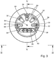
- FIG. 1 shows a preferred embodiment of an electric machine 30 according to the present invention in a perspective view.
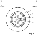
- the electric machine 30 comprises a longitudinal axis 24, along the extension of which are located an electric motor 15, a venting element 22 and a magnetic gear arrangement 20.
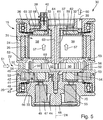
- the electric motor 15 may be an alternating current (AC) or a direct current (DC) motor. It is a brushless motor of the so-called outrunner type and comprises an internal stator 31 (see Figs. 5 and 8 ) with a first number of electric windings 32 in the form of wire coils disposed circumferentially around the longitudinal axis 24 of the electric machine 30.
- the stator 31 is connected to or forms part of a static component 33 of the electric machine 30.
- the stator 31 comprises a central carrier element 37 connected to or forming part of the static component 33.
- the carrier element 37 has an axial extension along the longitudinal axis 24.
- a first number of radially extending anchors 38 is attached to the carrier element 37.
- the wire coils of the electric windings 32 are wrapped around these anchors 38. End wires 39 of the electric windings 32 all end in an electric connector 40, which is provided with a total of three electric contacts, one for each of three phases of the electric motor 15.
- the electric motor 15 further comprises an external rotor 34 with a second number of permanent magnets 35 of polarities alternating in a circumferential direction.
- the rotor 34 rotates externally around the stator 31 about the longitudinal axis 24 during operation of the electric motor 15.
- Ball bearings 36 are provided between the static component 33 and the rotor 34.
- the ball bearings 36 may be part of a bearing ring or ball race.
- the electric machine 30 is provided with a total of six electric windings 32 and with a total of four permanent magnets 35. However, different numbers of electric windings 32 and permanent magnets 35 can be chosen depending on the individual requirements.
- the magnetic gear arrangement 20 is located in a manner displaced along the longitudinal axis 24 in respect to the electric motor 15.
- the magnetic gear arrangement 20 comprises a first rotating element 41 with a third number of permanent magnets 42 rotatable about the longitudinal axis 24 and indirectly connected to the external rotor 34 of the electric motor 15 by means of the venting element 22 in a torque-proof manner.
- Ball bearings 43 are provided between the static component 33 and the first rotating element 41.
- the ball bearings 43 may be part of a bearing ring or ball race.
- the magnetic gear arrangement 20 comprises a second rotating element 44 with a fourth number of permanent magnets 45 located internally in respect to the third number of permanent magnets 42.
- the second rotating element 44 can also rotate about the longitudinal axis 24 and is connected to an output shaft 46 of the electric machine 30 in a torque proof manner.
- the output shaft 46 is provided with an external thread.
- Ball bearings 47 are provided between the static component 33 and the second rotating element 44.
- the ball bearings 47 may be part of a bearing ring or ball race.
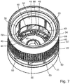
- the magnetic gear arrangement 20 comprises a static modulator 48 comprising a fifth number of ferromagnetic elements 49 disposed between the third number of permanent magnets 42 and the fourth number of permanent magnets 45.
- the modulator 48 is connected to or forms part of the static component 33.
- the polarities of the third and fourth number of permanent magnets 42, 45 alternate in a circumferential direction.
- the third number of permanent magnets 42 differs from the fourth number of permanent magnets 45.
- the magnetic gear arrangement 20 is provided with a total of four permanent magnets 42 of the first rotating element 41, two with positive polarity and two with negative polarity, and with a total of ten permanent magnets 45 of the second rotating element 44, five with positive polarity and five with negative polarity.
- the static modulator 48 comprises a total of seven ferromagnetic elements 49.
- different numbers of permanent magnets 42 and permanent magnets 45 can be chosen depending on the individual requirements.
- the number of ferromagnetic elements 49 of the static modulator 48 which depending on the individual requirements can differ from seven.
- the first rotating element 41 rotates faster than the second rotating element 44.
- the magnetic gear transmission 20 leads to a reduction of the rotational speed of the output shaft 46 (the output shaft 46 rotates slower than the rotor 34 of the motor 15) and to an increase of the torque which can be applied by the output shaft 46.
- the venting element 22 is located between the electric motor 15 and the magnetic gear arrangement 20.
- the venting element 22 comprises electrically isolating material, e.g. plastic or resin, and electrically isolates the electric motor 15 from the magnetic gear arrangement 20 and the output shaft 46, respectively.
- a plastic venting element 22 can be easily and cheaply manufactured, for example by injection moulding.
- the venting element 22 also rotates about the longitudinal axis 24.
- the venting element 22 is located between the external rotor 34 of the electric motor 15 and the first rotating element 41 of the magnetic gear arrangement 20 and rotates together with these parts.
- the venting element 22 is fixed to the external rotor 34 and to the first rotating element 41 in a torque proof manner.
- the venting element 22 is designed as a radial venting element providing for a radial air stream 51 into or out of the electric machine 30. It is provided with a plurality of venting blades 50 having an extension essentially parallel to the longitudinal axis 24 and with a radial component. In this embodiment the venting blades 50 are oriented such that during operation of the electric machine 30 and rotation in a given direction about the axis 24 an air stream 51 is drawn radially from the environment surrounding the electric machine 30 into an internal part of the electric machine 30. Preferably, in a view along the longitudinal axis 24, the venting blades 50 have an inclination of over 45° in respect to a radial direction (see Figs. 1 and 6 ).
- venting blades 50 can be modified in order to provide for an air stream 51 according to desired characteristics in term of direction and conveyed air volume.
- the venting blades 50 can have an even or plane extension or they can be curved about individual axes running parallel in respect to the longitudinal axis 24.
- the venting blades 50 can be provided with a reinforcing structure 52 (see Fig. 1 ).
- venting element 22 Due to the venting element 22 the electric machine 30 has very good cooling characteristics.
- the additional venting element 22 actively creates an air stream 51 for cooling the electric machine 30, in particular the electric motor 15, and more particular the internal stator 31 of the motor 15 with its electric stator windings 32.
- the venting element 22 has reinforcing metal sections 53, in particular at least one metal ring, embedded in or surrounding the electrically isolating material of the venting element 22, for safe attachment of the venting element 22 to the external rotor 34 of the electric motor 15 and/or to the first rotating element 41 of the magnetic gear arrangement 20.
- the metal sections 53 are provided in attachment regions of the venting element 22, where it is attached to the external rotor 34 and/or the first rotating element 41.
- the venting element 22 comprising the electrically isolating material and the reinforcing metal sections 53 is preferably manufactured by co-moulding.
- the venting element 22 could be fixedly attached to the external rotor 34 and/or the first rotating element 41 by means of a press-fit connection or a snap-lock connection.
- blocking elements (not shown) could be provided interacting between the venting element 22 and the external rotor 34 and/or between the venting element 22 and the first rotating element 41, in order to prevent a rotational displacement of the venting element 22 about the longitudinal axis 24 in respect to the external rotor 34 and/or the first rotating element 41.
- the blocking elements could comprise, for example, one or more protrusions (e.g. pins) interacting with respective depressions (e.g. holes).
- the electric machine 30 has the advantage that the venting element 22 also provides for an electric isolation between the electric motor 15 and the magnetic gear arrangement 20 and the output shaft 46, respectively.
- the electric machine 30 can fulfil the requirements of a double-isolated electric machine without the necessity of additional isolating elements.
- the electrically isolating material of the venting element 22 is located and dimensioned such that the formation of electric arcs between the electric motor 15 and the magnetic gear arrangement 20, in particular the output shaft 46, is prevented even if in exceptional cases high voltages (3.750 V or higher) are applied to the electric motor 15 by accident or for reasons of malfunction or defects of the electric machine 30.
- a modular design can be easily realised with the electric machine 30. This can be achieved, for example, by realizing the electric motor 15, the venting element 22 and the magnetic gear arrangement 20 as separate devices, which can be fixedly attached to one another during manufacturing of the electric machine 30.
- a specific electric motor 15 having the desired characteristics can be selected from a plurality of available electric motors with different characteristics.
- the desired output power may depend on the appliance, in which the electric machine 30 is used, and/or the gear ratio of the magnetic gear arrangement 20 used.
- a specific venting element 22 having the desired cooling characteristics can be selected from a plurality of available venting elements with different cooling characteristics.
- the desired degree of cooling may depend on the type of electric motor 15 used and/or an external environmental temperature.
- a specific magnetic gear arrangement 20 having the desired gear ratio can be selected from a plurality of available magnetic gear arrangements with different gear ratios.
- the desired gear ratio may depend on a desired torque value and/or rotational speed of the output shaft 46.
- the selected electric motor 15, venting element 22 and magnetic gear arrangement 20 are then fixedly attached to one another in order to form the modular electric machine 30.
- the attachment regions between the plurality of electric motors 15 and venting elements 22 on the one hand and between the plurality of venting elements 22 and magnetic gear arrangements 20 on the other hand are compatible with one another, in order to allow attachment of any selected electric motor 15 to any selected venting element 22 and of any selected venting element 22 to any selected magnetic gear arrangement 20.
- the aspirated air stream 51 may be used for cooling the internal part of the entire electric machine 30, including the electric motor 15 and the magnetic gear arrangement 20.
- the electric machine 30 has air guiding elements which guide a bigger part (airflow 57) of the air stream 51 coming from the venting element 22 towards the electric motor 15.
- a cover plate 54 is used as an air guiding element. It covers most part of the magnetic gear arrangement 20 thereby separating it from the venting element 22, leaving only a small annular air gap 56 between an outer circumference of the cover plate 54 and an internal surface of a lower part of the venting element 22 directed towards the magnetic gear arrangement 20.
- the cover plate 54 is attached to the output shaft 46 by means of a central screw 55 and rotates together with the second rotating element 44 of the magnetic gear arrangement 20.
- the cover plate 54 guides the bigger part 57 of the air stream 51 coming from the venting element 22 towards the electric motor 15 and in particular along the electric stator windings 32.
- the electric machine 30 comprises an upper end wall 58 separating the electric motor 15 from the environment, with at least one venting opening 59 which opens towards the internal stator 31 of the electric motor 15.
- the venting openings 59 allow an air stream 51 to flow from the environment, through the venting element 22 along the internal electric stator windings 32 and through the venting openings 59 as air stream 60 back into the environment or vice versa.
- a printed circuit board (PCB) 61 for the electric connector 40 and other electric and electronic components (not shown), e.g.
- a microprocessor, of the electric machine 30 is located between the internal stator 31 of the electric motor 15 and the upper end wall 58, it is suggested that the PCB 61 is equipped with through holes 62 corresponding in position and size to the venting openings 59 of the upper end wall 58.
- the airflow 57 running through the electric machine 30 also provides for cooling of the PCB 61 and the electric and electronic components attached thereto.
- the electric motor 15 has no internal motor shaft because the torque produced by the electric motor 15 is transmitted by means of the external rotor 34.
- the space, where in conventional electric motors the internal motor shaft is located, can be used for other components.
- the internal stator 31 comprises the central carrier element 37 which comprises a venting channel 63 with a longitudinal extension along the longitudinal axis 24 and leading into a central opening 64 in the upper end wall 58 of the electric machine 30. Hence, an additional internal cooling effect is achieved. Part of the cooling airflow 57 provoked by the venting element 22 will flow through the venting channel 63 of the central carrier element 37.
- Heat created in the wire coils of the electric windings 32 during operation of the electric motor 15 is directly transferred to the anchors 38 and further to the central carrier element 37 by thermal conduction. At least some of the heat is then transferred to the air flowing through the venting channel 63 and dissipated into the environment through the opening 64.
- the additional internal cooling of the electric stator 31 of the electric motor 15 supplements the external cooling of the stator 31 achieved by means of the airflow 57 running along the wire coils of the electric windings 32, thereby achieving a particularly efficient cooling of the electric motor 15.
- the venting element 22 may support the third number of permanent magnets 42 of the first rotating element 41 of the magnetic gear arrangement 20.
- the third number of permanent magnets 42 may be integrated in the venting element 22 (e.g. by co-moulding) or they may be formed separately from the venting element 22 and attached thereto. It could also be possible that the venting element 22 and the first rotating element 41 are one and the same part provided with a third number of receiving sections into which the permanent magnets 42 of the first rotating element 41 are inserted. Alternatively, it could be possible that the third number of permanent magnets 42 of the first rotating element 41 are held between a part of the venting element 22 directed towards the magnetic gear arrangement 20 and a part of the first rotating element 41 of the magnetic gear arrangement 20 facing the venting element 22. By fixedly attaching the venting element 22 to the first rotating element 41, the permanent magnets 42 are held (e.g. clamped) in their respective positions.
- the electric motor 15 has permanent magnets 35 which rotate around the fixed stator 31, eliminating problems associated with connecting current to a moving stator.
- An electronic controller e.g. provided on the PCB 61 or externally replaces the brush/ commutator assembly of a brushed DC motor and continually switches the phase to the windings 32 to keep the motor 15 turning.
- the controller performs similar timed electric power distribution by using a solid-state circuit with semiconductor switches such as transistors rather than the brush/commutator system.
- the electronic controller requires information in respect to the current rotational position (angle) of the rotor 34.
- the angular information can be deduced from electric values (e.g. voltage curve, current curve) of the motor 15 without the use of dedicated angular sensors.
- this requires an electronic controller with a microprocessor which operates at a very high clock rate. The required clock rate increases with the rotational speed of the electric motor 15 and the rate at which the polarities of the electric stator windings 32 are switched.
- the electric machine 30 comprises at least one first contactless position detection sensor 65 for determining a rotational position (angle) of the external rotor 34 of the electric motor 15 in respect to the internal stator 31.
- a sensor 65 By detecting the current angle of the rotor 34 by means of a sensor 65, an electronic controller with a microprocessor which operates at a lower clock rate can be used for the commutation.
- the sensor 65 is preferably embodied as a Hall-sensor. When a current flows through a Hall element, it delivers a voltage transversely to the current flow through the action of a perpendicular magnetic field.
- the Hall-sensor 65 can deliver a voltage through the action of the magnetic field created by the permanent magnets 35, thereby allowing detection of the angular position of the permanent magnets 35 and of the rotor 34.
- the sensor 65 is preferably attached to the static component 33 or the internal stator 31 of the motor 15, which makes it particularly easy to contact in order to provide electric energy (e.g. an electric current) to the sensor 65 and to tap a sensor signal (e.g. an electric voltage) created by the sensor 65 during operation of the electric machine 30.
- electric energy e.g. an electric current
- sensor signal e.g. an electric voltage
- bearings 36 which have a contactless position detection sensor integrated therein.
- the use of the sensor 65 provides for a precise, safe and reliable switching of the polarities of the electric stator windings 32 for operation of the electric machine 30.
- the electric machine 30 comprises at least one second contactless position detection sensor 66 for determining a rotational position of the second rotating element 44 of the gear transmission 20 and/or of the output shaft 46 of the electric machine 30 in respect to the static component 33. From the current position over time a rotational speed can be determined. By detecting the current speed of the output shaft 46 with the sensor 66, an electronic controller of the electric machine 30 can control the speed of the output shaft 46 by means of a closed loop control in order to maintain it constantly at a desired value independent of external influences (e.g. a requested load or torque value).
- the sensor 66 is preferably embodied as a Hall-sensor. The sensor 66 may detect the magnetic field created by the permanent magnets 45 of the second rotating element 44.
- the sensor 66 is preferably attached to the static component 33 or the static modulator 49 of the magnetic gear arrangement 20, which makes it particularly easy to contact for providing electric energy (e.g. an electric current) to the sensor 66 and for tapping a sensor signal (e.g. an electric voltage) created by the sensor 66 during operation of the electric machine 30.
- electric energy e.g. an electric current
- sensor signal e.g. an electric voltage
- the rotor 34 of the electric motor 15 is made of metal, e.g. aluminium. At least part of its external surface may be provided with fins 67 (see Fig. 1 ) preferably extending parallel to the longitudinal axis 24. These fins 67 increase the external surface area of the rotor 34, thereby providing for an enhanced cooling effect. Further, during operation of the electric machine 30 the fins 67 rotate together with the rotor 34 and create air turmoils in the environment surrounding the electric machine 30. This avoids accumulation of hot air in a housing of an appliance in which the electric machine 30 is used, for example in the housing 2 of a power tool 1 (see Figs. 9 and 10 ). These air turmoils provide for a better exchange of the air contained in the housing and for a more efficient cooling of the electric machine 30.
- the first rotating part 41 of the magnetic gear arrangement 20 is made of metal, e.g. aluminium.
- the venting element 22 is preferably made of a plastic material with reinforcing metal inserts 53 in its attachment regions where it is attached to the rotor 34 and the first rotating part 41.
- the second rotating part 44 of the magnetic gear arrangement 20 is preferably made of a plastic material.
- the output shaft 46 is preferably made of metal, e.g. aluminium.
- the static component 33 is preferably made of metal, e.g. aluminium.
- the cover plate 54 is preferably made of a plastic material. The second rotating part 44 of the magnetic gear arrangement 20 and the cover plate 54 could be realized as one and the same component.
- the static modulator 48 is preferably attached to the lower static component 33 by means of screws 68 (see Fig. 7 ).
- the second rotating part 44 of the magnetic gear arrangement 20 is preferably attached to the output shaft 46 by means of the central screw 55.
- blocking elements could be provided interacting between the second rotating part 44 and the output shaft 46, in order to prevent the rotational displacement of the output shaft 46 about the longitudinal axis 24 in respect to the second rotating part 44.
- the blocking elements could comprise, for example, one or more protrusions (e.g. pins) interacting with respective depressions (e.g. holes).
- the second rotating part 44 comprises a receiving section 69 into which an insertion part 70 of the output shaft 46 is inserted and thereafter fixed by means of the central screw 55 in a direction parallel to the longitudinal axis 24.
- the outer circumferential surface of the insertion part 70 corresponds to the inner circumferential surface of the receiving section 69.
- the inner circumferential surface of the receiving section 69 as well as the outer circumferential surface of the insertion part 70 are both not rotationally symmetric in respect to the longitudinal axis 24 (see Fig. 7 ). They have, for example, the form of a triangle, a rectangle or any other polygonal form.
- the inner circumferential surface of the receiving section 69 has an annular form with plane or even surfaces on two opposing sides. In this way a torque can be transmitted from the second rotating part 44 to the output shaft 46.
- the electric machine 30 comprises three units rotating at different speeds in respect to one another.
- a first static unit comprises the static component 33, the stator 31 with the carrier element 37, the anchors 38 and the electric windings 32, the upper end wall 58, the PCB 61 with the connector 40, and the static modulator 48 with the ferromagnetic elements 49.
- a second fast rotating unit comprises the rotor 34 with the permanent magnets 35, the venting element 22 with the venting blades 50 and the first rotating part 41 with the permanent magnets 42.
- the fast rotating second unit is rotatably mounted to the static first unit by means of the ball bearings 36, 43.
- a third unit rotating slower than the second unit comprises the second rotating element 44 with the permanent magnets 45, the cover plate 54 and the output shaft 46.
- the slowly rotating third unit is rotatably mounted to the static first unit by means of the ball bearings 47.
- the electric machine 30 according to the invention can be used in any electric appliance.
- Figs. 9 and 10 show an example for such an appliance in the form of an electric power tool 1.
- the power tool 1 equipped with the electric machine 30 is particularly calm during operation (a result of low vibrations and low noise of the electric machine 30), small in dimensions and light in weight (a result of the highly integrated, compact and lightweight electric machine 30), powerful (a result of the overall design of the electric machine 30, including the enhanced cooling of the electric motor 15, allowing an efficient operation) and safe (a result of the double-insulated design of the electric machine 30).
- the power tool 1 is shown as a polishing machine (polisher), alternatively the power tool 1 could be any one of a sander, a grinder, a drill, a percussion drill and an electric screwdriver.
- Fig. 9 shows another embodiment of the present invention. All the above explanations previously made in respect to the first embodiment shown in Figs. 1 to 8 shall apply to the embodiment of Fig. 9 , too, unless explicitly mentioned otherwise in the following.
- the venting element 50 is no longer attached to the external rotor 34 of the electric motor 15 and to the first rotating element 41 of the magnetic gear arrangement 20. Rather, it can be seen that the rotor 34 is directly attached to the first rotating element 41 in a torque proof manner. It can be further seen that the venting element 50 is attached to the second rotating part 44 of the magnetic gear arrangement 20.
- venting element 50 is located on a top surface of the cover plate 54 which is attached to the output shaft 46 by means of the central screw 55 and which rotates together with the second rotating element 44 of the magnetic gear arrangement 20.
- the venting element 50 could even be made in a single common part with the cover plate 54, as both are preferably made of plastic material.
- the connection between the venting element 50 and the second rotating part 44 of the magnetic gear arrangement 20 should be torque proof in order to make the venting element 50 rotate together with the second rotating part 44 during operation of the electric machine 30.
- This embodiment may have an advantage compared to the first embodiment in terms of structural stability of the fast rotating parts of the electric machine 30, in particular of the rotor 34 and the first rotating part 41. It may be slightly inferior to the first in terms of cooling efficiency stop nonetheless, the second embodiment also provides for an additional cooling of internal parts of the electric machine 30.
- venting element 50 rotates together with the second rotating part 44 of the magnetic gear arrangement 20.
- the venting element 50 being of the aspiration type will then create a cooling air stream 57 along the internal windings 32 of the starter 31 of the electric motor 15.
- air 50' from the environment will enter the electric machine, for example through the bearings 47, which do not seal the static element 33 and the output shaft 46 in an airtight manner.
- additional venting openings could be provided in the bottom part of the static element 33 connecting the environment with the second rotating part 44 or the venting element 50, respectively.
- the air could then flow through the magnetic gear arrangement 20 and the circular gap 56 provided between the fast rotating rotor 34 and first rotating part 41, respectively, on the one hand and an external circumferential border of the cover plate 54 and the venting element 50, respectively, on the other hand. Then, the air stream will continue to flow through the static part of the electric motor 15, in particular along the windings 32 and through the venting channel 63. Finally, the air stream 60 will leave the internal part of the electric machine 30 through the venting openings 59 and the central opening 64 provided in the upper end wall 58 and through the through holes 62 provided in the PCB 61, if present.
- Fig. 12 In contrast to what is shown in Fig. 9 , it would be possible to realise the rotor 34 and the first rotating element 41 as a single common part. Such an embodiment is shown in Fig. 12 . In that embodiment, instead of providing two separate sets of permanent magnets, the second number of permanent magnets 35 for the rotor 34 and the third number of permanent magnets 42 for the first rotating part 41, these permanent magnets 35, 42 are each realised as single common magnets extending all the way from the rotor 34 to the first rotating part 41.
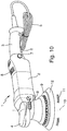
- Fig. 10 shows an example of a hand held and hand guided electric power tool 1 according to the present invention in a perspective view.
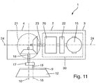
- Fig. 11 shows a schematic longitudinal section through the power tool 1 of Fig. 10 .
- the power tool 1 is embodied as a random orbital polishing machine (or polisher).
- the polisher 1 has a housing 2, essentially made of a plastic material.
- the housing 2 is provided with a handle 3 at its rear end and a grip 4 at its front end in order to allow a user of the tool 1 to hold the tool 1 with both hands and apply a certain amount of pressure on the grip 4 during the intended use of the tool 1.
- An electric power supply line 5 with an electric plug at its distal end exits the housing 2 at the rear end of the handle 3.
- a switch 6 is provided for activating and deactivating the power tool 1.
- the switch 6 can be continuously held in its activated position by means of a push button 7.
- the power tool 1 can be provided with adjustment means (not shown) for setting the rotational speed of the tool's electric motor 15 (see Fig. 11 ) located inside the housing 2 to a desired value.
- the housing 2 can be provided with cooling openings 8 for allowing heat from electronic components and/or the electric motor 15 both located inside the housing 2 to dissipate into the environment and/or for allowing cooling air from the environment to enter into the housing 2.
- the power tool 1 shown in Fig. 10 has an electric motor 15.
- the electric motor 15 is preferably of the brushless type.
- the tool 1 could additionally or alternatively be equipped with a rechargeable or exchangeable battery (not shown) located at least partially inside the housing 2. In that case the electric energy for driving the electric motor 15 and for operating the other electronic components of the tool 1 would be provided by the battery. If despite the presence of a battery the electric cable 5 was still present, the battery could be charged with an electric current from the mains power supply before, during or after operation of the power tool 1.
- the presence of a battery would allow the use of an electric motor 15 which is not operated at the mains power supply voltage (230V in Europe or 110V in the US and other countries), but rather at a reduced voltage of, for example, 12V, 24V, 36V or 42V depending on the voltage provided by the battery.
- the power tool 1 has a disk-like working element 9 (or backing pad) rotatable about a rotational axis 10.
- the working element 9 of the tool 1 shown in Fig. 10 performs a random orbital rotational movement 11.
- the working element 9 performs a first rotational movement about a first rotational axis corresponding to rotational axis 10.
- another second axis 16 (see Fig. 11 ) is defined about which the working element 9 is freely rotatable independently from the rotation of the working element 9 about the first rotational axis 10.
- the second axis 16 runs through the balance point of the working element 9 and parallel to the rotational axis 10.
- the random orbital movement 11 is realized by means of an eccentric element 17 attached to a tool shaft 18 in a torque proof manner and in which a rotational shaft 19 of the working element 9 is held and guided freely rotatable about axis 16.
- the working element 9 is made of a semi-rigid material, preferably a plastic material, which on the one hand is rigid enough to carry and support a tool accessory 12 for performing a desired work (e.g. polishing or sanding the surface of a vehicle body, a boat or aircraft hull) during the intended use of the power tool 1 and to apply a force to the working element 9 and the tool accessory 12 in a direction downwards and essentially parallel to the working element's rotational axis 10 and which on the other hand is flexible enough to avoid damage or scratching of a surface to be worked by the working element 9 or the tool accessory 12, respectively.
- a desired work e.g. polishing or sanding the surface of a vehicle body, a boat or aircraft hull
- the tool accessory 12 may be a polishing material comprising but not limited to a foam or sponge pad, a microfiber pad, and a real or synthetic lambs' wool pad.
- the tool accessory 12 is embodied as a foam or sponge pad.
- the bottom surface of the working element 9 is provided with means for releasably attaching the tool accessory 12.
- the attachment means can comprise a first layer of a hook-and-loop fastener (or Velcro®) on the bottom surface of the working element 9, wherein the top surface of the tool accessory 12 is provided with a corresponding second layer of the hook-and-loop fastener.
- the two layers of the hook-and-loop fastener interact with one another in order to releasably but safely fix the tool accessory 12 to the bottom surface of the working element 9.
- the working element 9 and the tool accessory 12 may be embodied differently.
- the power tool 1 according to the present invention can be any type of power tool provided with a working element 9 performing some kind of working movement (purely rotational, roto-orbital (gear driven), random orbital or purely orbital).
- the electric motor 15 makes part of an electric machine 30 according to the present invention which also comprises a magnetic gear arrangement 20 as well as a venting element 22 located between the electric motor 15 and the magnetic gear arrangement 20.
- the magnetic gear arrangement 20 is of the coaxial type, where a rotating input element (an external rotor of the electric motor 5) rotates about the same longitudinal axis 24 of the electric machine 30 as an output shaft 23.
- the power tool one is provided with a bevel gear arrangement 21 for translating a rotation of the output axis about the longitudinal axis 24 into a rotation of the tool shaft 18 about the rotational axis 10.
- the rotational speeds of the output shaft 23 and of the tool shaft 18 may be the same or defer from one another.
- the bevel gear arrangement 21 is necessary because the power tool 1 is an angular polisher, where the output shaft 23 runs in a certain angle (preferably between 90° and below 180°) in respect to the tool shaft 18. In the shown embodiment the angle is exactly 90°.
- the present invention has been explained by means of one possible embodiment in the form of an electric machine 30 for use in an angular random orbital polisher 1.
- the electric machine 30 according to the present invention can be used in a variety of other appliances, too.
- the working element 9 may perform one of a purely rotational, a random-orbital a roto-orbital (gear driven) and a purely orbital working movement 11.
Landscapes
- Engineering & Computer Science (AREA)
- Power Engineering (AREA)
- Mechanical Engineering (AREA)
- Microelectronics & Electronic Packaging (AREA)
- Connection Of Motors, Electrical Generators, Mechanical Devices, And The Like (AREA)
- Motor Or Generator Frames (AREA)
- Motor Or Generator Cooling System (AREA)
Claims (14)
- Machine électrique (30) comprenant un moteur électrique (15) et un dispositif d'engrenage magnétique (20),- dans lequel le moteur électrique (15) est un moteur sans balais,- dans lequel le moteur électrique (15) comprend- un stator (31) avec un premier nombre d'enroulements électriques (32) sous la forme de bobines de fil disposées circonférentiellement autour d'un axe longitudinal (24) de la machine électrique (30) et- un rotor (34) avec un deuxième nombre d'aimants permanents (35) de polarités alternées pouvant tourner par rapport au stator (31) autour de l'axe longitudinal (24) pendant le fonctionnement du moteur électrique (15),- dans lequel l'agencement d'engrenage magnétique (20) est situé d'une manière déplacée le long de l'axe longitudinal (24) par rapport au moteur électrique (15), et- dans lequel le dispositif d'engrenage magnétique (20) comprend- un premier élément magnétique (41) avec un troisième nombre d'aimants permanents (42),- un deuxième élément magnétique (44) avec un quatrième nombre d'aimants permanents (45), et- un modulateur (48) comprenant un cinquième nombre d'éléments ferromagnétiques (49) disposés entre le troisième nombre d'aimants permanents (42) et le quatrième nombre d'aimants permanents (45),- dans lequel le premier élément magnétique (41), le deuxième élément magnétique (44) et le modulateur (48) peuvent tourner l'un par rapport à l'autre autour de l'axe longitudinal, dans lequel l'un des éléments (41, 44) ou le modulateur (48) est connecté au rotor (34) du moteur électrique (15) d'une manière résistante au couple, et dans lequel un autre des éléments (41, 44) ou le modulateur (48) est connecté à un arbre de sortie (46) de la machine électrique (30) d'une manière résistante au couple, et- dans lequel le moteur électrique (15) comprend un stator interne (31) et un rotor externe (34) pouvant tourner extérieurement autour du stator (31) autour de l'axe longitudinal (24) pendant le fonctionnement du moteur électrique (15),caractérisé en ce que- un élément de ventilation (22) est fixé à ou fait partie d'au moins une des parties rotatives (34 ; 41 ; 44) de la machine électrique (30),- l'élément de ventilation (22) est situé entre le rotor externe (34) du moteur électrique (15) et le premier élément magnétique (41) du dispositif d'engrenage magnétique (20), et- l'élément d'aération (22) est constitué d'un matériau isolant électriquement, en particulier d'une matière plastique, isolant ainsi électriquement le moteur électrique (15) du dispositif d'engrenage magnétique (20).
- Machine électrique (30) selon la revendication 1, dans laquelle- le premier élément magnétique (41) peut tourner autour de l'axe longitudinal (24) et est relié au rotor externe (34) du moteur électrique (15) de manière à résister au couple,- le deuxième élément magnétique (44) est rotatif autour de l'axe longitudinal (24), situé à l'intérieur par rapport au troisième nombre d'aimants permanents (42) et connecté à l'arbre de sortie (46) de la machine électrique (30) de manière à résister au couple, et- le modulateur (48) est statique.
- Machine électrique (30) selon la revendication 1 ou 2, dans laquelle l'élément de ventilation (22) comprend des sections métalliques de renforcement (53), en particulier au moins un anneau métallique, noyé dans ou entourant le matériau d'isolation électrique de l'élément de ventilation (22), pour une fixation sûre de l'élément de ventilation (22) sur l'au moins une des parties rotatives (34 ; 41 ; 44).
- Machine électrique (30) selon l'une des revendications précédentes, dans laquelle l'élément de ventilation (22) est fixé au rotor externe (34) du moteur électrique (15) et au premier élément magnétique (41) du dispositif d'engrenage magnétique (20) de manière à résister au couple.
- Machine électrique (30) selon l'une des revendications précédentes, dans laquelle l'élément de ventilation (22) supporte le troisième nombre d'aimants permanents (42) du premier élément magnétique (41) du dispositif d'engrenages (20).
- Machine électrique (30) selon l'une des revendications précédentes, dans laquelle l'élément de ventilation (22) est conçu comme un élément de ventilation radial prévoyant un flux d'air radial (51) dans ou hors de la machine électrique (30).
- Machine électrique (30) selon la revendication 6, dans laquelle l'élément de ventilation (22) comprend une pluralité de lames d'aération (50) ayant une extension essentiellement parallèle à l'axe longitudinal (24) et avec une composante radiale, les lames d'aération (50) étant orientées de telle sorte que pendant le fonctionnement de la machine électrique (30), le flux d'air (51) est aspiré radialement à travers l'élément de ventilation (22).
- Machine électrique (30) selon la revendication 6 ou 7, dans laquelle la machine électrique (30) a au moins un élément de guidage d'air (54) qui guide une plus grande partie (57) du flux d'air radial (51) provenant de l'élément de ventilation (22) vers le moteur électrique (15) ou qui guide une plus grande partie du flux d'air provenant du moteur électrique (15) vers l'élément de ventilation (22).
- Machine électrique (30) selon l'une des revendications précédentes, dans laquelle la machine électrique (30) comprend une paroi d'extrémité supérieure (58) avec au moins une ouverture de ventilation (59) qui s'ouvre vers le stator interne (31) du moteur électrique (15).
- Machine électrique (30) selon l'une des revendications précédentes, dans laquelle le stator interne (31) comprend un élément porteur central (37) ayant une extension axiale le long de l'axe longitudinal (24), auquel est fixé le premier nombre d'ancrages (38) s'étendant radialement autour desquels les bobines de fil des enroulements électriques (32) sont enroulées, dans laquelle l'élément porteur central (37) comprend un canal de ventilation (63) ayant une extension axiale le long de l'axe longitudinal (24) et menant à une ouverture centrale (64) dans une paroi d'extrémité supérieure (58) de la machine électrique (30).
- Machine électrique (30) selon l'une des revendications précédentes, dans laquelle la machine électrique (30) comprend au moins un premier capteur de détection de position sans contact (65) pour déterminer une position de rotation du rotor externe (34) du moteur électrique (15) par rapport au stator interne (31).
- Machine électrique (30) selon l'une des revendications précédentes, dans laquelle la machine électrique (30) comprend au moins un deuxième capteur de détection de position sans contact (66) pour déterminer une position de rotation du deuxième élément magnétique (44) de la transmission d'engrenage (20) et/ou de l'arbre de sortie (46) de la machine électrique (30).
- Outil électrique (1) comprenant un boîtier (2) et un moteur électrique (15) et un dispositif d'engrenage magnétique (20) tous deux situés à l'intérieur du boîtier (2), et comprenant en outre un arbre d'outil (18) auquel est fixé un élément de travail (9), dans lequel le moteur électrique (15) et le dispositif d'engrenage magnétique (20) font partie d'une machine électrique (30) selon l'une des revendications précédentes.
- Outil électrique (1) selon la revendication 13, dans lequel l'outil électrique (1) est l'un parmi une ponceuse, un polisseur, une meuleuse, une perceuse, une perceuse à percussion et un tournevis électrique, et/ou dans lequel l'élément de travail (9) effectue l'un parmi un mouvement de travail purement rotatif, un mouvement orbital aléatoire, un mouvement roto-orbital et un mouvement purement orbital.
Priority Applications (3)
| Application Number | Priority Date | Filing Date | Title |
|---|---|---|---|
| EP18183964.8A EP3598613B1 (fr) | 2018-07-17 | 2018-07-17 | Moteur électrique avec agencement d'engrenage magnétique |
| US16/460,500 US11165297B2 (en) | 2018-07-17 | 2019-07-02 | Electric motor with magnetic gear arrangement |
| CN201910602290.XA CN110729853B (zh) | 2018-07-17 | 2019-07-05 | 具有磁性齿轮布置的电动机 |
Applications Claiming Priority (1)
| Application Number | Priority Date | Filing Date | Title |
|---|---|---|---|
| EP18183964.8A EP3598613B1 (fr) | 2018-07-17 | 2018-07-17 | Moteur électrique avec agencement d'engrenage magnétique |
Publications (2)
| Publication Number | Publication Date |
|---|---|
| EP3598613A1 EP3598613A1 (fr) | 2020-01-22 |
| EP3598613B1 true EP3598613B1 (fr) | 2021-09-08 |
Family
ID=62981097
Family Applications (1)
| Application Number | Title | Priority Date | Filing Date |
|---|---|---|---|
| EP18183964.8A Active EP3598613B1 (fr) | 2018-07-17 | 2018-07-17 | Moteur électrique avec agencement d'engrenage magnétique |
Country Status (3)
| Country | Link |
|---|---|
| US (1) | US11165297B2 (fr) |
| EP (1) | EP3598613B1 (fr) |
| CN (1) | CN110729853B (fr) |
Families Citing this family (5)
| Publication number | Priority date | Publication date | Assignee | Title |
|---|---|---|---|---|
| AU2020269749B2 (en) * | 2019-05-08 | 2023-11-16 | Lg Electronics Inc. | Blender |
| CN111697780B (zh) * | 2020-06-22 | 2023-02-17 | 深圳市吉胜华力科技有限公司 | 一种电磁涡流离合器风扇 |
| DE102020119589A1 (de) | 2020-07-24 | 2022-01-27 | Intrasys Gmbh Innovative Transportsysteme | Wicklungsanordnung für einen Linearmotor mit parallel angeordneten Spulenpaaren aus einem zusammenhängenden elektrischen Leiter |
| EP3967457B1 (fr) | 2020-09-10 | 2024-03-20 | Guido Valentini | Outil électrique à batterie guidé à la main |
| EP4063660A1 (fr) * | 2021-03-26 | 2022-09-28 | Hilti Aktiengesellschaft | Machine-outil avec un arbre moteur et une roue de ventilateur, comportant un accouplement magnétique entre l'arbre de moteur et la roue de ventilateur |
Citations (1)
| Publication number | Priority date | Publication date | Assignee | Title |
|---|---|---|---|---|
| JP2011033166A (ja) * | 2009-08-05 | 2011-02-17 | Mitsubishi Electric Corp | 磁気ギヤおよびそれを搭載した車両 |
Family Cites Families (16)
| Publication number | Priority date | Publication date | Assignee | Title |
|---|---|---|---|---|
| GB2194686A (en) * | 1986-09-03 | 1988-03-09 | Johnson Electric Ind Mfg | Electric motor with velocity indicating device |
| JP2001298922A (ja) * | 2000-04-10 | 2001-10-26 | Fuji Electric Co Ltd | バーニアモータ |
| ITMI20030961A1 (it) * | 2003-05-14 | 2004-11-15 | Guido Valentini | Utensile motorizzato con capacita' di aspirazione e raccolta polvere. |
| ATE411473T1 (de) * | 2004-03-16 | 2008-10-15 | Ebm Papst St Georgen Gmbh & Co | Anordnung mit einem elektronisch kommutierten aussenläufermotor |
| GB2457226B (en) * | 2008-01-11 | 2013-01-09 | Magnomatics Ltd | Drives for sealed systems |
| US7804215B2 (en) * | 2008-09-30 | 2010-09-28 | General Electric Company | Integrated cooling concept for magnetically geared machine |
| CN201608593U (zh) * | 2009-12-18 | 2010-10-13 | 刘志广 | 一种集成有散热装置的永磁同步曳引机电机 |
| US8446060B1 (en) * | 2010-01-12 | 2013-05-21 | Richard H. Lugg | Magnetic advanced gas-turbine transmission with radial aero-segmented nanomagnetic-drive (MAGTRAN) |
| WO2011159674A1 (fr) * | 2010-06-14 | 2011-12-22 | Black & Decker Inc. | Ensemble stator pour moteur sans balai dans un outil électrique |
| JP2012147513A (ja) * | 2011-01-07 | 2012-08-02 | Hitachi Ltd | 磁気ギヤ及びそれを有する回転機 |
| CN102611222B (zh) * | 2012-02-22 | 2014-10-29 | 北京交通大学 | 自带齿轮式搅风结构的电机通风系统 |
| US8985253B2 (en) * | 2013-02-05 | 2015-03-24 | Honda Motor Co., Ltd. | Generators and vehicles having auxiliary power generation systems |
| US10253676B2 (en) * | 2013-12-20 | 2019-04-09 | Magna Powertrain Bad Homburg GmbH | Molded rotor for cooling fan motor |
| FR3026246B1 (fr) * | 2014-09-18 | 2018-03-30 | Moteurs Leroy-Somer | Machine electrique tournante comportant au moins un stator et au moins deux rotors. |
| CN106329859A (zh) * | 2015-06-17 | 2017-01-11 | 香港理工大学 | 双转子对旋式永磁无刷风力发电机 |
| CN107355528A (zh) * | 2016-05-10 | 2017-11-17 | 德昌电机(深圳)有限公司 | 一种驱动装置及应用该驱动装置的电动工具 |
-
2018
- 2018-07-17 EP EP18183964.8A patent/EP3598613B1/fr active Active
-
2019
- 2019-07-02 US US16/460,500 patent/US11165297B2/en active Active
- 2019-07-05 CN CN201910602290.XA patent/CN110729853B/zh active Active
Patent Citations (1)
| Publication number | Priority date | Publication date | Assignee | Title |
|---|---|---|---|---|
| JP2011033166A (ja) * | 2009-08-05 | 2011-02-17 | Mitsubishi Electric Corp | 磁気ギヤおよびそれを搭載した車両 |
Also Published As
| Publication number | Publication date |
|---|---|
| EP3598613A1 (fr) | 2020-01-22 |
| CN110729853B (zh) | 2021-11-05 |
| CN110729853A (zh) | 2020-01-24 |
| US11165297B2 (en) | 2021-11-02 |
| US20200028396A1 (en) | 2020-01-23 |
Similar Documents
| Publication | Publication Date | Title |
|---|---|---|
| EP3598613B1 (fr) | Moteur électrique avec agencement d'engrenage magnétique | |
| US20220166283A1 (en) | Brushless motor for a power tool | |
| EP2391480B1 (fr) | Outil électrique | |
| EP3166213B1 (fr) | Outil electrique | |
| JP5435212B2 (ja) | ディスクグラインダ | |
| EP4250541A2 (fr) | Moteur sans balai à rotor externe doté d'un ventilateur axial | |
| US8628380B2 (en) | Direct motor-drive portable angle grinder | |
| US9662760B2 (en) | Hand-held power tool having an electronically commutated electric motor and an integrated electronics system | |
| EP3656503B1 (fr) | Outil électrique de ponçage ou de polissage orbital aléatoire guidé à la main portatif | |
| JP6460123B2 (ja) | 電動工具 | |
| EP3501753B1 (fr) | Outil à moteur électrique ou pneumatique guidé et/ou tenu à la main | |
| EP4087094A1 (fr) | Moteur sans balai à rotor externe et ensemble engrenage planétaire pour outil électrique | |
| KR20090010561U (ko) | 냉각팬이 내장된 bldc 모터 | |
| WO2022238623A1 (fr) | Ensemble arbre de rotor, procédé de fabrication d'ensemble arbre de rotor et dispositifs comprenant l'ensemble arbre de rotor | |
| PL215996B1 (pl) | Elektronarzędzie z napędem bezpośrednim, zwłaszcza ręczna szlifierka kątowa |
Legal Events
| Date | Code | Title | Description |
|---|---|---|---|
| PUAI | Public reference made under article 153(3) epc to a published international application that has entered the european phase |
Free format text: ORIGINAL CODE: 0009012 |
|
| STAA | Information on the status of an ep patent application or granted ep patent |
Free format text: STATUS: THE APPLICATION HAS BEEN PUBLISHED |
|
| AK | Designated contracting states |
Kind code of ref document: A1 Designated state(s): AL AT BE BG CH CY CZ DE DK EE ES FI FR GB GR HR HU IE IS IT LI LT LU LV MC MK MT NL NO PL PT RO RS SE SI SK SM TR |
|
| AX | Request for extension of the european patent |
Extension state: BA ME |
|
| STAA | Information on the status of an ep patent application or granted ep patent |
Free format text: STATUS: REQUEST FOR EXAMINATION WAS MADE |
|
| 17P | Request for examination filed |
Effective date: 20200722 |
|
| RBV | Designated contracting states (corrected) |
Designated state(s): AL AT BE BG CH CY CZ DE DK EE ES FI FR GB GR HR HU IE IS IT LI LT LU LV MC MK MT NL NO PL PT RO RS SE SI SK SM TR |
|
| GRAP | Despatch of communication of intention to grant a patent |
Free format text: ORIGINAL CODE: EPIDOSNIGR1 |
|
| STAA | Information on the status of an ep patent application or granted ep patent |
Free format text: STATUS: GRANT OF PATENT IS INTENDED |
|
| INTG | Intention to grant announced |
Effective date: 20210426 |
|
| GRAS | Grant fee paid |
Free format text: ORIGINAL CODE: EPIDOSNIGR3 |
|
| GRAA | (expected) grant |
Free format text: ORIGINAL CODE: 0009210 |
|
| STAA | Information on the status of an ep patent application or granted ep patent |
Free format text: STATUS: THE PATENT HAS BEEN GRANTED |
|
| AK | Designated contracting states |
Kind code of ref document: B1 Designated state(s): AL AT BE BG CH CY CZ DE DK EE ES FI FR GB GR HR HU IE IS IT LI LT LU LV MC MK MT NL NO PL PT RO RS SE SI SK SM TR |
|
| REG | Reference to a national code |
Ref country code: GB Ref legal event code: FG4D |
|
| REG | Reference to a national code |
Ref country code: AT Ref legal event code: REF Ref document number: 1429445 Country of ref document: AT Kind code of ref document: T Effective date: 20210915 Ref country code: CH Ref legal event code: EP |
|
| REG | Reference to a national code |
Ref country code: IE Ref legal event code: FG4D |
|
| REG | Reference to a national code |
Ref country code: DE Ref legal event code: R096 Ref document number: 602018023146 Country of ref document: DE |
|
| REG | Reference to a national code |
Ref country code: LT Ref legal event code: MG9D |
|
| REG | Reference to a national code |
Ref country code: NL Ref legal event code: MP Effective date: 20210908 |
|
| PG25 | Lapsed in a contracting state [announced via postgrant information from national office to epo] |
Ref country code: LT Free format text: LAPSE BECAUSE OF FAILURE TO SUBMIT A TRANSLATION OF THE DESCRIPTION OR TO PAY THE FEE WITHIN THE PRESCRIBED TIME-LIMIT Effective date: 20210908 Ref country code: BG Free format text: LAPSE BECAUSE OF FAILURE TO SUBMIT A TRANSLATION OF THE DESCRIPTION OR TO PAY THE FEE WITHIN THE PRESCRIBED TIME-LIMIT Effective date: 20211208 Ref country code: NO Free format text: LAPSE BECAUSE OF FAILURE TO SUBMIT A TRANSLATION OF THE DESCRIPTION OR TO PAY THE FEE WITHIN THE PRESCRIBED TIME-LIMIT Effective date: 20211208 Ref country code: FI Free format text: LAPSE BECAUSE OF FAILURE TO SUBMIT A TRANSLATION OF THE DESCRIPTION OR TO PAY THE FEE WITHIN THE PRESCRIBED TIME-LIMIT Effective date: 20210908 Ref country code: ES Free format text: LAPSE BECAUSE OF FAILURE TO SUBMIT A TRANSLATION OF THE DESCRIPTION OR TO PAY THE FEE WITHIN THE PRESCRIBED TIME-LIMIT Effective date: 20210908 Ref country code: HR Free format text: LAPSE BECAUSE OF FAILURE TO SUBMIT A TRANSLATION OF THE DESCRIPTION OR TO PAY THE FEE WITHIN THE PRESCRIBED TIME-LIMIT Effective date: 20210908 Ref country code: RS Free format text: LAPSE BECAUSE OF FAILURE TO SUBMIT A TRANSLATION OF THE DESCRIPTION OR TO PAY THE FEE WITHIN THE PRESCRIBED TIME-LIMIT Effective date: 20210908 Ref country code: SE Free format text: LAPSE BECAUSE OF FAILURE TO SUBMIT A TRANSLATION OF THE DESCRIPTION OR TO PAY THE FEE WITHIN THE PRESCRIBED TIME-LIMIT Effective date: 20210908 |
|
| REG | Reference to a national code |
Ref country code: AT Ref legal event code: MK05 Ref document number: 1429445 Country of ref document: AT Kind code of ref document: T Effective date: 20210908 |
|
| PG25 | Lapsed in a contracting state [announced via postgrant information from national office to epo] |
Ref country code: LV Free format text: LAPSE BECAUSE OF FAILURE TO SUBMIT A TRANSLATION OF THE DESCRIPTION OR TO PAY THE FEE WITHIN THE PRESCRIBED TIME-LIMIT Effective date: 20210908 Ref country code: GR Free format text: LAPSE BECAUSE OF FAILURE TO SUBMIT A TRANSLATION OF THE DESCRIPTION OR TO PAY THE FEE WITHIN THE PRESCRIBED TIME-LIMIT Effective date: 20211209 |
|
| PG25 | Lapsed in a contracting state [announced via postgrant information from national office to epo] |
Ref country code: AT Free format text: LAPSE BECAUSE OF FAILURE TO SUBMIT A TRANSLATION OF THE DESCRIPTION OR TO PAY THE FEE WITHIN THE PRESCRIBED TIME-LIMIT Effective date: 20210908 |
|
| PG25 | Lapsed in a contracting state [announced via postgrant information from national office to epo] |
Ref country code: IS Free format text: LAPSE BECAUSE OF FAILURE TO SUBMIT A TRANSLATION OF THE DESCRIPTION OR TO PAY THE FEE WITHIN THE PRESCRIBED TIME-LIMIT Effective date: 20220108 Ref country code: SM Free format text: LAPSE BECAUSE OF FAILURE TO SUBMIT A TRANSLATION OF THE DESCRIPTION OR TO PAY THE FEE WITHIN THE PRESCRIBED TIME-LIMIT Effective date: 20210908 Ref country code: SK Free format text: LAPSE BECAUSE OF FAILURE TO SUBMIT A TRANSLATION OF THE DESCRIPTION OR TO PAY THE FEE WITHIN THE PRESCRIBED TIME-LIMIT Effective date: 20210908 Ref country code: RO Free format text: LAPSE BECAUSE OF FAILURE TO SUBMIT A TRANSLATION OF THE DESCRIPTION OR TO PAY THE FEE WITHIN THE PRESCRIBED TIME-LIMIT Effective date: 20210908 Ref country code: PT Free format text: LAPSE BECAUSE OF FAILURE TO SUBMIT A TRANSLATION OF THE DESCRIPTION OR TO PAY THE FEE WITHIN THE PRESCRIBED TIME-LIMIT Effective date: 20220110 Ref country code: PL Free format text: LAPSE BECAUSE OF FAILURE TO SUBMIT A TRANSLATION OF THE DESCRIPTION OR TO PAY THE FEE WITHIN THE PRESCRIBED TIME-LIMIT Effective date: 20210908 Ref country code: NL Free format text: LAPSE BECAUSE OF FAILURE TO SUBMIT A TRANSLATION OF THE DESCRIPTION OR TO PAY THE FEE WITHIN THE PRESCRIBED TIME-LIMIT Effective date: 20210908 Ref country code: EE Free format text: LAPSE BECAUSE OF FAILURE TO SUBMIT A TRANSLATION OF THE DESCRIPTION OR TO PAY THE FEE WITHIN THE PRESCRIBED TIME-LIMIT Effective date: 20210908 Ref country code: CZ Free format text: LAPSE BECAUSE OF FAILURE TO SUBMIT A TRANSLATION OF THE DESCRIPTION OR TO PAY THE FEE WITHIN THE PRESCRIBED TIME-LIMIT Effective date: 20210908 Ref country code: AL Free format text: LAPSE BECAUSE OF FAILURE TO SUBMIT A TRANSLATION OF THE DESCRIPTION OR TO PAY THE FEE WITHIN THE PRESCRIBED TIME-LIMIT Effective date: 20210908 |
|
| REG | Reference to a national code |
Ref country code: DE Ref legal event code: R097 Ref document number: 602018023146 Country of ref document: DE |
|
| PLBE | No opposition filed within time limit |
Free format text: ORIGINAL CODE: 0009261 |
|
| STAA | Information on the status of an ep patent application or granted ep patent |
Free format text: STATUS: NO OPPOSITION FILED WITHIN TIME LIMIT |
|
| PG25 | Lapsed in a contracting state [announced via postgrant information from national office to epo] |
Ref country code: DK Free format text: LAPSE BECAUSE OF FAILURE TO SUBMIT A TRANSLATION OF THE DESCRIPTION OR TO PAY THE FEE WITHIN THE PRESCRIBED TIME-LIMIT Effective date: 20210908 |
|
| 26N | No opposition filed |
Effective date: 20220609 |
|
| PG25 | Lapsed in a contracting state [announced via postgrant information from national office to epo] |
Ref country code: SI Free format text: LAPSE BECAUSE OF FAILURE TO SUBMIT A TRANSLATION OF THE DESCRIPTION OR TO PAY THE FEE WITHIN THE PRESCRIBED TIME-LIMIT Effective date: 20210908 |
|
| REG | Reference to a national code |
Ref country code: DE Ref legal event code: R082 Ref document number: 602018023146 Country of ref document: DE Representative=s name: WOERZ PATENTANWAELTE PARTNERSCHAFTSGESELLSCHAF, DE |
|
| PG25 | Lapsed in a contracting state [announced via postgrant information from national office to epo] |
Ref country code: MC Free format text: LAPSE BECAUSE OF FAILURE TO SUBMIT A TRANSLATION OF THE DESCRIPTION OR TO PAY THE FEE WITHIN THE PRESCRIBED TIME-LIMIT Effective date: 20210908 |
|
| REG | Reference to a national code |
Ref country code: CH Ref legal event code: PL |
|
| REG | Reference to a national code |
Ref country code: BE Ref legal event code: MM Effective date: 20220731 |
|
| PG25 | Lapsed in a contracting state [announced via postgrant information from national office to epo] |
Ref country code: LU Free format text: LAPSE BECAUSE OF NON-PAYMENT OF DUE FEES Effective date: 20220717 Ref country code: LI Free format text: LAPSE BECAUSE OF NON-PAYMENT OF DUE FEES Effective date: 20220731 Ref country code: CH Free format text: LAPSE BECAUSE OF NON-PAYMENT OF DUE FEES Effective date: 20220731 |
|
| PG25 | Lapsed in a contracting state [announced via postgrant information from national office to epo] |
Ref country code: BE Free format text: LAPSE BECAUSE OF NON-PAYMENT OF DUE FEES Effective date: 20220731 |
|
| P01 | Opt-out of the competence of the unified patent court (upc) registered |
Effective date: 20230513 |
|
| PG25 | Lapsed in a contracting state [announced via postgrant information from national office to epo] |
Ref country code: IE Free format text: LAPSE BECAUSE OF NON-PAYMENT OF DUE FEES Effective date: 20220717 |
|
| PGFP | Annual fee paid to national office [announced via postgrant information from national office to epo] |
Ref country code: IT Payment date: 20230731 Year of fee payment: 6 Ref country code: GB Payment date: 20230724 Year of fee payment: 6 |
|
| PGFP | Annual fee paid to national office [announced via postgrant information from national office to epo] |
Ref country code: FR Payment date: 20230724 Year of fee payment: 6 Ref country code: DE Payment date: 20230922 Year of fee payment: 6 |
|
| PG25 | Lapsed in a contracting state [announced via postgrant information from national office to epo] |
Ref country code: HU Free format text: LAPSE BECAUSE OF FAILURE TO SUBMIT A TRANSLATION OF THE DESCRIPTION OR TO PAY THE FEE WITHIN THE PRESCRIBED TIME-LIMIT; INVALID AB INITIO Effective date: 20180717 |
|
| PG25 | Lapsed in a contracting state [announced via postgrant information from national office to epo] |
Ref country code: MK Free format text: LAPSE BECAUSE OF FAILURE TO SUBMIT A TRANSLATION OF THE DESCRIPTION OR TO PAY THE FEE WITHIN THE PRESCRIBED TIME-LIMIT Effective date: 20210908 Ref country code: CY Free format text: LAPSE BECAUSE OF FAILURE TO SUBMIT A TRANSLATION OF THE DESCRIPTION OR TO PAY THE FEE WITHIN THE PRESCRIBED TIME-LIMIT Effective date: 20210908 |