EP3598564A1 - Passive protection battery module structure and manufacturing method therefor - Google Patents
Passive protection battery module structure and manufacturing method therefor Download PDFInfo
- Publication number
- EP3598564A1 EP3598564A1 EP17900751.3A EP17900751A EP3598564A1 EP 3598564 A1 EP3598564 A1 EP 3598564A1 EP 17900751 A EP17900751 A EP 17900751A EP 3598564 A1 EP3598564 A1 EP 3598564A1
- Authority
- EP
- European Patent Office
- Prior art keywords
- fireproof
- thermally insulating
- insulating spacer
- battery cells
- battery
- Prior art date
- Legal status (The legal status is an assumption and is not a legal conclusion. Google has not performed a legal analysis and makes no representation as to the accuracy of the status listed.)
- Granted
Links
Images

Classifications
-
- H—ELECTRICITY
- H01—ELECTRIC ELEMENTS
- H01M—PROCESSES OR MEANS, e.g. BATTERIES, FOR THE DIRECT CONVERSION OF CHEMICAL ENERGY INTO ELECTRICAL ENERGY
- H01M10/00—Secondary cells; Manufacture thereof
- H01M10/04—Construction or manufacture in general
-
- H—ELECTRICITY
- H01—ELECTRIC ELEMENTS
- H01M—PROCESSES OR MEANS, e.g. BATTERIES, FOR THE DIRECT CONVERSION OF CHEMICAL ENERGY INTO ELECTRICAL ENERGY
- H01M10/00—Secondary cells; Manufacture thereof
- H01M10/60—Heating or cooling; Temperature control
- H01M10/61—Types of temperature control
- H01M10/613—Cooling or keeping cold
-
- H—ELECTRICITY
- H01—ELECTRIC ELEMENTS
- H01M—PROCESSES OR MEANS, e.g. BATTERIES, FOR THE DIRECT CONVERSION OF CHEMICAL ENERGY INTO ELECTRICAL ENERGY
- H01M10/00—Secondary cells; Manufacture thereof
- H01M10/04—Construction or manufacture in general
- H01M10/0468—Compression means for stacks of electrodes and separators
-
- H—ELECTRICITY
- H01—ELECTRIC ELEMENTS
- H01M—PROCESSES OR MEANS, e.g. BATTERIES, FOR THE DIRECT CONVERSION OF CHEMICAL ENERGY INTO ELECTRICAL ENERGY
- H01M10/00—Secondary cells; Manufacture thereof
- H01M10/60—Heating or cooling; Temperature control
- H01M10/62—Heating or cooling; Temperature control specially adapted for specific applications
- H01M10/625—Vehicles
-
- H—ELECTRICITY
- H01—ELECTRIC ELEMENTS
- H01M—PROCESSES OR MEANS, e.g. BATTERIES, FOR THE DIRECT CONVERSION OF CHEMICAL ENERGY INTO ELECTRICAL ENERGY
- H01M10/00—Secondary cells; Manufacture thereof
- H01M10/60—Heating or cooling; Temperature control
- H01M10/64—Heating or cooling; Temperature control characterised by the shape of the cells
- H01M10/647—Prismatic or flat cells, e.g. pouch cells
-
- H—ELECTRICITY
- H01—ELECTRIC ELEMENTS
- H01M—PROCESSES OR MEANS, e.g. BATTERIES, FOR THE DIRECT CONVERSION OF CHEMICAL ENERGY INTO ELECTRICAL ENERGY
- H01M10/00—Secondary cells; Manufacture thereof
- H01M10/60—Heating or cooling; Temperature control
- H01M10/65—Means for temperature control structurally associated with the cells
- H01M10/658—Means for temperature control structurally associated with the cells by thermal insulation or shielding
-
- H—ELECTRICITY
- H01—ELECTRIC ELEMENTS
- H01M—PROCESSES OR MEANS, e.g. BATTERIES, FOR THE DIRECT CONVERSION OF CHEMICAL ENERGY INTO ELECTRICAL ENERGY
- H01M50/00—Constructional details or processes of manufacture of the non-active parts of electrochemical cells other than fuel cells, e.g. hybrid cells
- H01M50/20—Mountings; Secondary casings or frames; Racks, modules or packs; Suspension devices; Shock absorbers; Transport or carrying devices; Holders
- H01M50/233—Mountings; Secondary casings or frames; Racks, modules or packs; Suspension devices; Shock absorbers; Transport or carrying devices; Holders characterised by physical properties of casings or racks, e.g. dimensions
- H01M50/24—Mountings; Secondary casings or frames; Racks, modules or packs; Suspension devices; Shock absorbers; Transport or carrying devices; Holders characterised by physical properties of casings or racks, e.g. dimensions adapted for protecting batteries from their environment, e.g. from corrosion
-
- H—ELECTRICITY
- H01—ELECTRIC ELEMENTS
- H01M—PROCESSES OR MEANS, e.g. BATTERIES, FOR THE DIRECT CONVERSION OF CHEMICAL ENERGY INTO ELECTRICAL ENERGY
- H01M2200/00—Safety devices for primary or secondary batteries
- H01M2200/10—Temperature sensitive devices
-
- H—ELECTRICITY
- H01—ELECTRIC ELEMENTS
- H01M—PROCESSES OR MEANS, e.g. BATTERIES, FOR THE DIRECT CONVERSION OF CHEMICAL ENERGY INTO ELECTRICAL ENERGY
- H01M2220/00—Batteries for particular applications
- H01M2220/20—Batteries in motive systems, e.g. vehicle, ship, plane
-
- Y—GENERAL TAGGING OF NEW TECHNOLOGICAL DEVELOPMENTS; GENERAL TAGGING OF CROSS-SECTIONAL TECHNOLOGIES SPANNING OVER SEVERAL SECTIONS OF THE IPC; TECHNICAL SUBJECTS COVERED BY FORMER USPC CROSS-REFERENCE ART COLLECTIONS [XRACs] AND DIGESTS
- Y02—TECHNOLOGIES OR APPLICATIONS FOR MITIGATION OR ADAPTATION AGAINST CLIMATE CHANGE
- Y02E—REDUCTION OF GREENHOUSE GAS [GHG] EMISSIONS, RELATED TO ENERGY GENERATION, TRANSMISSION OR DISTRIBUTION
- Y02E60/00—Enabling technologies; Technologies with a potential or indirect contribution to GHG emissions mitigation
- Y02E60/10—Energy storage using batteries
-
- Y—GENERAL TAGGING OF NEW TECHNOLOGICAL DEVELOPMENTS; GENERAL TAGGING OF CROSS-SECTIONAL TECHNOLOGIES SPANNING OVER SEVERAL SECTIONS OF THE IPC; TECHNICAL SUBJECTS COVERED BY FORMER USPC CROSS-REFERENCE ART COLLECTIONS [XRACs] AND DIGESTS
- Y02—TECHNOLOGIES OR APPLICATIONS FOR MITIGATION OR ADAPTATION AGAINST CLIMATE CHANGE
- Y02P—CLIMATE CHANGE MITIGATION TECHNOLOGIES IN THE PRODUCTION OR PROCESSING OF GOODS
- Y02P70/00—Climate change mitigation technologies in the production process for final industrial or consumer products
- Y02P70/50—Manufacturing or production processes characterised by the final manufactured product
Definitions
- the present application relates to PACK for power batteries, more particularly to a battery module structure with passive protection and a fabrication method thereof.
- the ternary battery is advantageous over the phosphoric acid iron batteries in energy densities, but worse in safety.
- the latest announced subsidies for new energy vehicles are tightly linked to the energy density of battery systems of electric vehicles, but the traditional phosphoric acid iron batteries cannot meet higher requirements for the energy density.
- a battery module with passive protection structure and a fabrication method thereof are provided by the present invention as a technical solution to the deficiencies of the prior art, which improve the safety of the ternary batteries and delay or even avoid a chain reaction caused by an overheated individual battery cell.
- the present invention provides a battery module structure with passive protection, comprising: a plurality of battery cells 4, a fireproof and thermally insulating spacer 3 and a casing; the plurality of battery cells 4 are arranged in the casing, and the fireproof and thermally insulating spacer 3 is provided between the battery cells 4; and the fireproof and thermally insulating spacer 3 comprises a substrate coated with a fireproof and thermally insulating coating made of a material that foams when heated.
- the substrate of the fireproof and thermally insulating spacer 3 is a mica sheet; a thickness of the mica sheet is 0.2 mm with an error range of 0.02 mm; and a thickness of the fireproof and thermally insulating coating is 0.3 mm with an error range of 0.03 mm; and the mica sheet is coated with the fireproof and thermally insulating coating on one side, and the other side of the mica sheet is coated with an adhesive to bond with a battery cell 4 adjacent to the fireproof and thermally insulating spacer.
- the fireproof and thermally insulating coating of the fireproof and thermally insulating spacer 3 is evenly coated on the substrate and foams to absorb a heat conducted by the substrate at a preset temperature.
- the casing comprises end plates 1 on both ends and a side plate 2 on a side; the battery cells 4, the fireproof and thermally insulating spacer 3 provided therebetween and the end plates 1 on both ends are integrally bonded by a double-sided adhesive with a high viscosity; and the end plates 1 are riveted with the side plate 2 through a rivet.
- the present invention provides a fabrication method of the battery module structure with passive protection, comprising the following steps:
- the step of fixing of the fireproof and thermally insulating spacer 3 between the battery cells 4 comprises the following steps: bonding the battery cells 4 and the fireproof and thermally insulating spacer 3 therebetween via the double-sided adhesive with a high viscosity, and fixing the battery cells and the fireproof and thermally insulating spacer by a pressure transferred from the end plates 1 on both ends.
- the fabrication method further comprises: after a fireproof and thermally insulating coating is applied on the substrate of the fireproof and thermally insulating spacer 3, performing a corona treatment on the fireproof thermal insulation coating.
- the battery module structure with passive protection and the fabrication method thereof are provided by the present invention.
- the battery cells of the battery module are respectively spaced by the fireproof and thermally insulating spacer; and an excellent thermal insulation is achieved by the fireproof and thermally insulating spacer due to a mica sheet and the endothermic foaming of the fireproof and thermally insulating coating when heated, such that the risk of having a thermal runaway or even breaking the explosion-proof valve when the battery cells are overheated is effectively delayed or avoided in case that the adjacent battery cell is overcharged or has a thermal runaway under a high temperature. This gives sufficient time for people in the vehicle to evacuate, ensuring the personnel safety.
- a battery module with passive protection which comprises a plurality of battery cells 4, a fireproof and thermally insulating spacer 3 and a casing.
- the battery cells 4 are provided in the casing, and the fireproof and thermally insulating spacer 3 is provided between the battery cells 4 and comprises a substrate 31 coated with a fireproof and thermally insulating coating 32 made of a material that foams when heated.
- the battery cells in the battery module are respectively spaced by the fireproof and thermally insulating spacer 3.
- An excellent thermal insulation can be achieved by the fireproof and thermally insulating spacer 3 due to a mica sheet and the endothermic foaming of the fireproof and thermally insulating coating when heated, such that the risk of having a thermal runaway or even breaking the explosion-proof valve when the battery cells are overheated can be effectively delayed or avoided in case that the adjacent battery cell is overcharged or has a thermal runaway under a high temperature. This gives sufficient time for people in the vehicle to evacuate, ensuring the personnel safety.
- the substrate 31 of the fireproof and thermally insulating spacer 3 is a mica sheet; a thickness of the mica sheet is 0.2 mm with an error range of 0.02 mm, e.g. the thickness of the substrate 31 could be 0.2 mm.
- the thickness of the fireproof and thermally insulating coating could be 0.3mm with an error range of 0.03 mm, e.g. the thickness of the fireproof and thermally insulating coating could be 0.3 mm.
- the mica sheet is coated with the fireproof and thermally insulating coating on one side, and the other side of mica sheet is covered with an adhesive. The adhesive fixes the fireproof and thermally insulating spacer 3 with a battery cell 4 by bonding.
- the fireproof and thermally insulating coating 31 of the fireproof and thermally insulating spacer 3 is evenly coated on the substrate 31 and massively absorbs the heat conducted by the substrate by foaming rapidly at a preset temperature (e.g. at a temperature of 120°C), and the purpose of fireproofing and thermal insulation is achieved through the chemical foaming mechanism.
- the casing comprises end plates 1 on both ends and a side plate 2 on a side.
- the battery cells 4, the fireproof and thermally insulating spacer 3 provided therebetween and the end plates 1 on both ends are integrally bonded by a double-sided adhesive with a high viscosity; and the end plates 1 are riveted with the side plate 2 through a rivet, such that the battery cells 4 and the fireproof and thermally insulating spacer 3 are packaged in the casing.
- the battery module with passive protection has various embodiments, and a preferred embodiment of the battery module with passive protection will be described in detail with reference to FIGS. 1-4 .
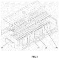
- a battery module with passive protection with 20 battery cells comprising two end plates 1, two side plates 2, 19 fireproof and thermally insulating spacers 3 and 20 ternary VDA battery cells 4.
- Each end of the 20 ternary VDA battery cells 4 is arranged with an end plate 1.
- the ternary VDA battery cell 4 and the fireproof and thermally insulating spacers 3 are pressed to a desire size by a pressure device and are firmly bonded by a double-sided adhesive.
- the end plates 1 are riveted with the side plates 2 through a rivet.
- the 20 ternary VDA battery cells 4 are respectively spaced by the fireproof and thermally insulating spacers 3, and with the adhesive 33 on the fireproof thermally and insulating spacer 3 and the double-sided adhesive with the high viscosity, the ternary VDA battery cells 4 are firmly bonded with the fireproof and thermally insulating spacers 3.
- the size of a rivet hole on the side plate 2 is designed to be sufficient when the ternary VDA battery cells 4 and the fireproof and thermally insulating spacers 3 are pressed to a desired size with a preset pressure that is over 100Kg, such that the side plates 2 are riveted with the end plates 1 by a stainless steel rivet of shear resistance as a whole frame after the rivet holes on the side plates 2 aligned with the rivet holes on the end plates 1.
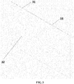
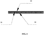
- the fireproof and thermally insulating spacer 3 comprises a mica sheet substrate 31, the fireproof and thermally insulating coating 32 and the adhesive 33 on a back of the mica sheet.
- the mica sheet substrate 31 contains more than 90% mica and has a bending strength of at least 160 MPa, which provides a sufficient mechanical strength while having a great thermal insulation and insulation performance, so the required strength of the substrate for applying the fireproof and thermally insulating coatings is reached.
- the chemical compositions of the fireproof and thermally insulating coating 32 has a polymer structure which can rapidly foam at a high temperature to absorb a large amount of heat, achieving the purpose of fireproofing and thermal insulation through a chemical foaming mechanism.
- the double-sided adhesive between the ternary VDA battery cell 4 and the fireproof and thermally insulating spacer 3 and the adhesive 33 on the fireproof and thermally insulating spacer 3 are required to withstand a high temperature of at least 80°C and with a viscosity larger than 24 hrs/0.5 Kg.
- the safety of the battery module is greatly improved by providing a spacer excellent in fireproofing and thermal insulating between the ternary VDA battery cells of the battery module with passive protection of the embodiment, which prevents the abnormality of one battery cell from spreading over the whole battery module and causes no threat to personnel safety.
- Step 102 the battery cells 4 and the fireproof and thermally insulating spacers 3 are bonded via the double-sided adhesive with a high viscosity and are fixed by a pressure transferred from the end plates 1 on both ends.
- the fabrication method further comprises the following steps: after the fireproof and thermally insulating coating is applied on the substrate of the fireproof and thermally insulating spacer 3, the corona treatment is performed on the fireproof and thermally insulating coating, such that the battery cell is firmly bonded with the double-sided adhesive.
- the fabrication method is provided based on the battery module with passive protection provided in the first aspect. It should be noted that the fabrication method will change as the battery module with passive protection changes, so it will not be limited herein.
- the battery cells in the battery module are respectively spaced by the fireproof and thermally insulating spacers.
- An excellent thermal insulation can be achieved by the fireproof and thermally insulating spacers due to a mica sheet and the endothermic foaming of the fireproof and thermally insulating coating when heated, such that the risk of having a thermal runaway or even breaking the explosion-proof valve when the battery cells are overheated can be effectively delayed or avoided in case that the adjacent battery cell is overcharged or has a thermal runaway under a high temperature. This gives sufficient time for people in the vehicle to evacuate, ensuring the personnel safety.
- the present invention provides a battery module with passive protection and a fabrication thereof, relating to PACK of the power battery.
- the cells in the battery module are respectively spaced by the fireproof and thermally insulating spacers.
- An excellent thermal insulation can be provided by the fireproof and thermally insulating spacer due to a mica sheet and the endothermic foaming of the fireproof and thermally insulating coating when heated, such that the risk of having a thermal runaway or even breaking the explosion-proof valve when the battery cells are overheated can be effectively delayed or avoided in case that the adjacent battery cell is overcharged or has a thermal runaway under a high temperature, which gives sufficient time for people in the vehicle to evacuate, thus ensuring the personnel safety. Therefore, the present application has excellent industrial application prospects.
Landscapes
- Chemical & Material Sciences (AREA)
- Chemical Kinetics & Catalysis (AREA)
- Electrochemistry (AREA)
- General Chemical & Material Sciences (AREA)
- Engineering & Computer Science (AREA)
- Manufacturing & Machinery (AREA)
- Battery Mounting, Suspending (AREA)
- Secondary Cells (AREA)
Abstract
Description
- The present application relates to PACK for power batteries, more particularly to a battery module structure with passive protection and a fabrication method thereof.
- Safety of power vehicles has become a focus of people's attention as the power vehicles are popularized, especially for the ternary batteries. The ternary battery is advantageous over the phosphoric acid iron batteries in energy densities, but worse in safety. As the subsidy policy changes, the latest announced subsidies for new energy vehicles are tightly linked to the energy density of battery systems of electric vehicles, but the traditional phosphoric acid iron batteries cannot meet higher requirements for the energy density.
- However, chemical components of the ternary battery has a strong activity, which may lead to the thermal runaway under a temperature over 120°C, and the battery cell is overcharged due to the failure of the battery management system (BMS), which may cause dangerous accidents to damage personnel safety.
- Therefore, it is of great importance to improve the safety of the ternary battery with ternary battery cells when an energy density of the battery pack is higher than 120 Wh/Kg and to ensure the safety of people in the vehicle when extreme circumstances such as overheating of individual battery cells occur.
- A battery module with passive protection structure and a fabrication method thereof are provided by the present invention as a technical solution to the deficiencies of the prior art, which improve the safety of the ternary batteries and delay or even avoid a chain reaction caused by an overheated individual battery cell.
- In a first aspect, the present invention provides a battery module structure with passive protection, comprising: a plurality of
battery cells 4, a fireproof and thermally insulatingspacer 3 and a casing;
the plurality ofbattery cells 4 are arranged in the casing, and the fireproof and thermally insulatingspacer 3 is provided between thebattery cells 4; and the fireproof and thermally insulatingspacer 3 comprises a substrate coated with a fireproof and thermally insulating coating made of a material that foams when heated. - In some embodiments, the substrate of the fireproof and thermally insulating
spacer 3 is a mica sheet; a thickness of the mica sheet is 0.2 mm with an error range of 0.02 mm; and a thickness of the fireproof and thermally insulating coating is 0.3 mm with an error range of 0.03 mm; and the mica sheet is coated with the fireproof and thermally insulating coating on one side, and the other side of the mica sheet is coated with an adhesive to bond with abattery cell 4 adjacent to the fireproof and thermally insulating spacer. - In some embodiments, the fireproof and thermally insulating coating of the fireproof and thermally insulating
spacer 3 is evenly coated on the substrate and foams to absorb a heat conducted by the substrate at a preset temperature. - In some embodiments, the casing comprises
end plates 1 on both ends and aside plate 2 on a side; thebattery cells 4, the fireproof and thermally insulatingspacer 3 provided therebetween and theend plates 1 on both ends are integrally bonded by a double-sided adhesive with a high viscosity; and theend plates 1 are riveted with theside plate 2 through a rivet. - In the second aspect, the present invention provides a fabrication method of the battery module structure with passive protection, comprising the following steps:
- providing
battery cells 4 in the casing; - fixing the fireproof and thermally insulating
spacer 3 between thebattery cells 4; wherein the fireproof and thermally insulatingspacer 3 comprises the substrate coated with the fireproof and thermally insulating coating made of the material that foams when heated; and - applying a pressure larger than a preset pressure to a
battery cell 4 via theend plates 1 on both ends of the casing to move theend plates 1 on both ends towards thebattery cells 4, and fixing theend plates 1 with theside plate 2 of the casing through the rivet after reaching a limit position. - In some embodiments, the step of fixing of the fireproof and thermally insulating
spacer 3 between thebattery cells 4 comprises the following steps:
bonding thebattery cells 4 and the fireproof and thermally insulatingspacer 3 therebetween via the double-sided adhesive with a high viscosity, and fixing the battery cells and the fireproof and thermally insulating spacer by a pressure transferred from theend plates 1 on both ends. - In some embodiments, the fabrication method further comprises:
after a fireproof and thermally insulating coating is applied on the substrate of the fireproof and thermally insulatingspacer 3, performing a corona treatment on the fireproof thermal insulation coating. - The battery module structure with passive protection and the fabrication method thereof are provided by the present invention. In the provided battery module with passive protection, the battery cells of the battery module are respectively spaced by the fireproof and thermally insulating spacer; and an excellent thermal insulation is achieved by the fireproof and thermally insulating spacer due to a mica sheet and the endothermic foaming of the fireproof and thermally insulating coating when heated, such that the risk of having a thermal runaway or even breaking the explosion-proof valve when the battery cells are overheated is effectively delayed or avoided in case that the adjacent battery cell is overcharged or has a thermal runaway under a high temperature. This gives sufficient time for people in the vehicle to evacuate, ensuring the personnel safety.
-
-
FIG. 1 is a perspective view of a battery module structure with passive protection with 20 battery cells according to an embodiment of the present invention; -
FIG. 2 is an exploded view of the battery module structure with passive protection with 20 battery cells according to an embodiment of the present invention; -
FIG. 3 is a perspective view of a fireproof and thermally insulating spacer according to an embodiment of the present invention; and -
FIG. 4 is a partial enlarged view of the fireproof and thermally insulating spacer according to an embodiment of the present invention. - The embodiments of the present invention will be thoroughly described in conjunction with the accompanying drawings to further illustrate the objectives, technical solutions, and advantages of the present invention. Apparently, the mentioned embodiments are only a part of the embodiments of the present invention. All other embodiments obtained by the skilled in the art based on the embodiments of the present invention without creative efforts shall fall within the scope of the present invention.
- In the first aspect, as shown in
FIGS. 1-4 , illustrated is a battery module with passive protection, which comprises a plurality ofbattery cells 4, a fireproof and thermally insulatingspacer 3 and a casing. - The
battery cells 4 are provided in the casing, and the fireproof and thermally insulatingspacer 3 is provided between thebattery cells 4 and comprises asubstrate 31 coated with a fireproof and thermally insulatingcoating 32 made of a material that foams when heated. - In this embodiment, the battery cells in the battery module are respectively spaced by the fireproof and thermally insulating
spacer 3. An excellent thermal insulation can be achieved by the fireproof and thermally insulatingspacer 3 due to a mica sheet and the endothermic foaming of the fireproof and thermally insulating coating when heated, such that the risk of having a thermal runaway or even breaking the explosion-proof valve when the battery cells are overheated can be effectively delayed or avoided in case that the adjacent battery cell is overcharged or has a thermal runaway under a high temperature. This gives sufficient time for people in the vehicle to evacuate, ensuring the personnel safety. - In some embodiments, the
substrate 31 of the fireproof and thermally insulatingspacer 3 is a mica sheet; a thickness of the mica sheet is 0.2 mm with an error range of 0.02 mm, e.g. the thickness of thesubstrate 31 could be 0.2 mm. The thickness of the fireproof and thermally insulating coating could be 0.3mm with an error range of 0.03 mm, e.g. the thickness of the fireproof and thermally insulating coating could be 0.3 mm. The mica sheet is coated with the fireproof and thermally insulating coating on one side, and the other side of mica sheet is covered with an adhesive. The adhesive fixes the fireproof and thermally insulatingspacer 3 with abattery cell 4 by bonding. - In some embodiments, the fireproof and thermally insulating
coating 31 of the fireproof and thermally insulatingspacer 3 is evenly coated on thesubstrate 31 and massively absorbs the heat conducted by the substrate by foaming rapidly at a preset temperature (e.g. at a temperature of 120°C), and the purpose of fireproofing and thermal insulation is achieved through the chemical foaming mechanism. - In some embodiments, the casing comprises
end plates 1 on both ends and aside plate 2 on a side. Thebattery cells 4, the fireproof and thermally insulatingspacer 3 provided therebetween and theend plates 1 on both ends are integrally bonded by a double-sided adhesive with a high viscosity; and theend plates 1 are riveted with theside plate 2 through a rivet, such that thebattery cells 4 and the fireproof and thermally insulatingspacer 3 are packaged in the casing. - It should be understood that the battery module with passive protection has various embodiments, and a preferred embodiment of the battery module with passive protection will be described in detail with reference to
FIGS. 1-4 . - In this embodiment, illustrated is a battery module with passive protection with 20 battery cells, comprising two
end plates 1, twoside plates 2, 19 fireproof and thermally insulatingspacers 3 and 20 ternaryVDA battery cells 4. Each end of the 20 ternaryVDA battery cells 4 is arranged with anend plate 1. The ternaryVDA battery cell 4 and the fireproof and thermally insulatingspacers 3 are pressed to a desire size by a pressure device and are firmly bonded by a double-sided adhesive. Theend plates 1 are riveted with theside plates 2 through a rivet. - The 20 ternary
VDA battery cells 4 are respectively spaced by the fireproof and thermally insulatingspacers 3, and with theadhesive 33 on the fireproof thermally andinsulating spacer 3 and the double-sided adhesive with the high viscosity, the ternaryVDA battery cells 4 are firmly bonded with the fireproof and thermally insulatingspacers 3. The size of a rivet hole on theside plate 2 is designed to be sufficient when the ternaryVDA battery cells 4 and the fireproof and thermally insulatingspacers 3 are pressed to a desired size with a preset pressure that is over 100Kg, such that theside plates 2 are riveted with theend plates 1 by a stainless steel rivet of shear resistance as a whole frame after the rivet holes on theside plates 2 aligned with the rivet holes on theend plates 1. - The fireproof and thermally insulating
spacer 3 comprises amica sheet substrate 31, the fireproof and thermally insulatingcoating 32 and theadhesive 33 on a back of the mica sheet. Themica sheet substrate 31 contains more than 90% mica and has a bending strength of at least 160 MPa, which provides a sufficient mechanical strength while having a great thermal insulation and insulation performance, so the required strength of the substrate for applying the fireproof and thermally insulating coatings is reached. The chemical compositions of the fireproof and thermally insulatingcoating 32 has a polymer structure which can rapidly foam at a high temperature to absorb a large amount of heat, achieving the purpose of fireproofing and thermal insulation through a chemical foaming mechanism. After the fireproof and thermally insulatingcoating 32 is coated on themica sheet substrate 31, a corona treatment is performed to ensure that the bonding between themica sheet substrate 31 and the ternary VDA battery cell through the double-sided adhesive is firm and reliable. The double-sided adhesive between the ternaryVDA battery cell 4 and the fireproof and thermally insulatingspacer 3 and theadhesive 33 on the fireproof and thermally insulatingspacer 3 are required to withstand a high temperature of at least 80°C and with a viscosity larger than 24 hrs/0.5 Kg. - The safety of the battery module is greatly improved by providing a spacer excellent in fireproofing and thermal insulating between the ternary VDA battery cells of the battery module with passive protection of the embodiment, which prevents the abnormality of one battery cell from spreading over the whole battery module and causes no threat to personnel safety.
- In the second aspect, illustrated is a fabrication method of the battery module with passive protection, comprising the following steps:
- S101) the
battery cells 4 are provided in the casing; - S102) the fireproof and thermally insulating
spacer 3 is provided between thebattery cells 4, where the fireproof and thermally insulatingspacer 3 comprises the substrate coated with the fireproof and thermally insulating coating made of the material that foams when heated; - S103) a pressure larger than the preset pressure is applied to the
battery cells 4 via theend plates 1 on both ends of the battery case to move theend plates 1 of both ends towards thebattery cell 4, and theend plates 1 are fixed with theside plate 2 of the casing through a rivet after reaching a limit position. - Further, in Step 102, the
battery cells 4 and the fireproof and thermally insulatingspacers 3 are bonded via the double-sided adhesive with a high viscosity and are fixed by a pressure transferred from theend plates 1 on both ends. - In addition, the fabrication method further comprises the following steps: after the fireproof and thermally insulating coating is applied on the substrate of the fireproof and thermally insulating
spacer 3, the corona treatment is performed on the fireproof and thermally insulating coating, such that the battery cell is firmly bonded with the double-sided adhesive. - The fabrication method is provided based on the battery module with passive protection provided in the first aspect. It should be noted that the fabrication method will change as the battery module with passive protection changes, so it will not be limited herein.
- In summary, in the battery module with passive protection and the fabrication method thereof provided by the embodiments of the present invention, the battery cells in the battery module are respectively spaced by the fireproof and thermally insulating spacers. An excellent thermal insulation can be achieved by the fireproof and thermally insulating spacers due to a mica sheet and the endothermic foaming of the fireproof and thermally insulating coating when heated, such that the risk of having a thermal runaway or even breaking the explosion-proof valve when the battery cells are overheated can be effectively delayed or avoided in case that the adjacent battery cell is overcharged or has a thermal runaway under a high temperature. This gives sufficient time for people in the vehicle to evacuate, ensuring the personnel safety.
- The above embodiments are only an illustration rather than a limiting to the technical solutions of the present invention. It should be noted that modifications of the technical solutions described in the foregoing embodiments or equivalent replacements of the technical features can be made by the skilled in the art based on the present application, which shall fall within the scope of the present invention.
- The present invention provides a battery module with passive protection and a fabrication thereof, relating to PACK of the power battery. In the battery module with passive protection, the cells in the battery module are respectively spaced by the fireproof and thermally insulating spacers. An excellent thermal insulation can be provided by the fireproof and thermally insulating spacer due to a mica sheet and the endothermic foaming of the fireproof and thermally insulating coating when heated, such that the risk of having a thermal runaway or even breaking the explosion-proof valve when the battery cells are overheated can be effectively delayed or avoided in case that the adjacent battery cell is overcharged or has a thermal runaway under a high temperature, which gives sufficient time for people in the vehicle to evacuate, thus ensuring the personnel safety. Therefore, the present application has excellent industrial application prospects.
Claims (7)
- A battery module structure with passive protection, comprising a plurality of battery cells (4), a fireproof and thermally insulating spacer (3) and a casing;
characterized in that the battery cells (4) are arranged in the casing, and the fireproof and thermally insulating spacer (3) is provided between the battery cells (4); and
the fireproof and thermally insulating spacer (3) comprises a substrate (31) coated with a fireproof and thermally insulating coating (32) made of a material that foams when heated. - The battery module structure according to claim 1, characterized in that the substrate (31) of the fireproof and thermally insulating spacer (3) is a mica sheet; a thickness of the mica sheet is 0.2 mm with an error range of 0.02 mm; and a thickness of the fireproof and thermally insulating coating (32) is 0.3 mm with an error range of 0.03 mm; and
the mica sheet is coated with the fireproof and thermally insulating coating (32) on one side, and the other side of the mica sheet is coated with an adhesive (33) to bond with a battery cell (4) adjacent to the fireproof and thermally insulating spacer (3). - The battery module structure according to claim 1, characterized in that the fireproof and thermally insulating coating of the fireproof and thermally insulating spacer (3) is evenly coated on the substrate (31) and foams to absorb a heat conducted by the substrate at a preset temperature.
- The battery module structure according to claim 1, characterized in that the casing comprises end plates (1) on both ends and a side plate (2) on a side;
the battery cells (4), the fireproof and thermally insulating spacer (3) provided therebetween and the end plates (1) on both ends are integrally bonded by a double-sided adhesive with a high viscosity; and the end plates (1) are riveted with the side plate (2) through a rivet. - A fabrication method of the battery module structure according to any one of claims 1-4, comprising:providing the battery cells (4) in the casing;fixing the fireproof and thermally insulating spacer (3) between the battery cells (4); wherein the fireproof and thermally insulating spacer (3) comprises the substrate coated with the fireproof and thermally insulating coating made of the material that foams when heated; andapplying a pressure larger than a preset pressure to the battery cells (4) via the end plates (1) on both ends of the casing to move the end plates (1) on both ends towards the battery cells (4), and fixing the end plates (1) with the side plate (2) of the casing through the rivet after reaching a limit position.
- The fabrication method according to claim 5, characterized in that the step of fixing of the fireproof and thermally insulating spacer (3) between the battery cells (4) comprises the following steps:
bonding the battery cells (4) and the fireproof and thermally insulating spacer (3) therebetween via the double-sided adhesive with a high viscosity, and fixing the battery cells and the fireproof and thermally insulating spacer by a pressure transferred from the end plates (1) on both ends. - The fabrication method according to claim 5, further comprising:
after a fireproof and thermally insulating coating is applied on the substrate of the fireproof and thermally insulating spacer (3), performing a corona treatment on the fireproof thermal insulation coating.
Applications Claiming Priority (2)
| Application Number | Priority Date | Filing Date | Title |
|---|---|---|---|
| CN201710150039.5A CN106785225A (en) | 2017-03-14 | 2017-03-14 | Passive protection battery module structure and manufacturing method thereof |
| PCT/CN2017/109409 WO2018166216A1 (en) | 2017-03-14 | 2017-11-03 | Passive protection battery module structure and manufacturing method therefor |
Publications (4)
| Publication Number | Publication Date |
|---|---|
| EP3598564A1 true EP3598564A1 (en) | 2020-01-22 |
| EP3598564A4 EP3598564A4 (en) | 2020-12-02 |
| EP3598564B1 EP3598564B1 (en) | 2023-07-19 |
| EP3598564C0 EP3598564C0 (en) | 2023-07-19 |
Family
ID=58962628
Family Applications (1)
| Application Number | Title | Priority Date | Filing Date |
|---|---|---|---|
| EP17900751.3A Active EP3598564B1 (en) | 2017-03-14 | 2017-11-03 | Passive protection battery module structure and manufacturing method therefor |
Country Status (3)
| Country | Link |
|---|---|
| EP (1) | EP3598564B1 (en) |
| CN (1) | CN106785225A (en) |
| WO (1) | WO2018166216A1 (en) |
Cited By (3)
| Publication number | Priority date | Publication date | Assignee | Title |
|---|---|---|---|---|
| EP3828988A4 (en) * | 2019-03-06 | 2021-09-22 | LG Chem, Ltd. | ESS MODULE HAVING A STRUCTURE ALLOWING THE PREVENTION OF EXTERNAL EXPOSURE OF A FLAME, AND BATTERY PACK EQUIPPED WITH THIS MODULE |
| US11777158B2 (en) | 2018-02-06 | 2023-10-03 | Lg Energy Solution, Ltd. | Battery module and battery pack including same |
| US11870094B2 (en) | 2019-07-03 | 2024-01-09 | Lg Energy Solution, Ltd. | Battery module, battery rack comprising same, and power storage device |
Families Citing this family (36)
| Publication number | Priority date | Publication date | Assignee | Title |
|---|---|---|---|---|
| CN106785225A (en) * | 2017-03-14 | 2017-05-31 | 合肥国轩高科动力能源有限公司 | Passive protection battery module structure and manufacturing method thereof |
| CN107834632A (en) * | 2017-11-09 | 2018-03-23 | 威艾能源(惠州)有限公司 | A kind of battery bag |
| CN109888412B (en) * | 2017-12-06 | 2023-05-05 | 蔚来控股有限公司 | Battery system thermal runaway simulation device and simulation method |
| CN108899464B (en) * | 2018-07-02 | 2024-09-10 | 蜂巢能源(武汉)有限公司 | A busbar of a battery module and a battery module |
| CN209249548U (en) * | 2018-12-30 | 2019-08-13 | 宁德时代新能源科技股份有限公司 | A battery module and battery pack |
| CN111668404B (en) * | 2019-03-07 | 2024-12-03 | 宁德时代新能源科技股份有限公司 | Battery module and battery pack |
| CN112011293B (en) * | 2019-05-28 | 2022-10-04 | 3M创新有限公司 | Curable pressure-sensitive adhesive composition, curable pressure-sensitive adhesive tape and battery pack |
| JP7580400B2 (en) * | 2019-05-28 | 2024-11-11 | スリーエム イノベイティブ プロパティズ カンパニー | Curable pressure-sensitive adhesive composition, curable pressure-sensitive adhesive tape, and battery pack |
| CN110435269A (en) * | 2019-06-27 | 2019-11-12 | 惠州市保瑞新材料有限公司 | A kind of fire resistant composite material and preparation method |
| US12090354B2 (en) | 2019-09-05 | 2024-09-17 | Samsung Sdi Co., Ltd. | Energy storage module |
| US11735795B2 (en) | 2019-09-05 | 2023-08-22 | Samsung Sdi Co., Ltd. | Energy storage module |
| US12057598B2 (en) | 2019-09-05 | 2024-08-06 | Samsung Sdi Co., Ltd. | Energy storage module including extinguisher sheet |
| US11848461B2 (en) | 2019-09-05 | 2023-12-19 | Samsung Sdi Co., Ltd. | Energy storage module |
| US11764430B2 (en) | 2019-09-05 | 2023-09-19 | Samsung Sdi Co., Ltd. | Energy storage module |
| US12300848B2 (en) | 2019-09-05 | 2025-05-13 | Samsung Sdi Co., Ltd. | Energy storage module including extinguisher sheet |
| CN110459715A (en) * | 2019-09-05 | 2019-11-15 | 台州市黄岩双盛塑模有限公司 | Composite battery case |
| US12288895B2 (en) | 2019-09-05 | 2025-04-29 | Samsung Sdi Co., Ltd. | Energy storage module |
| US11764438B2 (en) | 2019-09-05 | 2023-09-19 | Samsung Sdi Co., Ltd. | Energy storage module having extinguisher sheet |
| US11728541B2 (en) | 2019-09-05 | 2023-08-15 | Samsung Sdi Co., Ltd. | Energy storage module |
| US12355098B2 (en) | 2019-09-05 | 2025-07-08 | Samsung Sdi Co., Ltd. | Energy storage module |
| US11569546B2 (en) | 2019-09-05 | 2023-01-31 | Samsung Sdi Co., Ltd. | Energy storage module |
| US11735788B2 (en) | 2019-09-05 | 2023-08-22 | Samsung Sdi Co., Ltd. | Energy storage module including insulation spacers and an extinguisher sheet |
| US11771935B2 (en) | 2019-09-05 | 2023-10-03 | Samsung Sdi Co., Ltd. | Energy storage module |
| US11799167B2 (en) | 2019-09-05 | 2023-10-24 | Samsung Sdi Co., Ltd. | Energy storage module having extinguisher sheet |
| CN110605777B (en) * | 2019-09-17 | 2024-04-30 | 苏州可川电子科技股份有限公司 | Process for solving problem of rubberizing of 3D (three-dimensional) mica surface |
| CN111129371A (en) * | 2019-12-24 | 2020-05-08 | 奇瑞新能源汽车股份有限公司 | Device and method for protecting thermal runaway of power battery of electric automobile |
| CN111293249B (en) * | 2020-03-13 | 2023-08-29 | 苏州清陶新能源科技有限公司 | Soft package battery module and assembly method thereof |
| CN113540657B (en) * | 2020-04-15 | 2022-10-14 | 上海汽车集团股份有限公司 | A method and device for thermal runaway impact protection of a high-efficiency power battery |
| CN111725454B (en) * | 2020-06-12 | 2022-11-22 | 上汽通用汽车有限公司 | Battery module and battery pack assembly |
| KR102929045B1 (en) * | 2020-08-07 | 2026-02-19 | 주식회사 엘지에너지솔루션 | Battery module and battery pack including the same |
| CN114141460B (en) * | 2020-09-03 | 2024-08-16 | 上海大学 | A fireproof packaging method for MOV |
| CN214068782U (en) * | 2021-01-18 | 2021-08-27 | 中国第一汽车股份有限公司 | Protective cover for delaying thermal runaway and battery assembly |
| CN113206338B (en) * | 2021-03-24 | 2024-08-16 | 合众新能源汽车股份有限公司 | A structure for delaying thermal runaway time of electric vehicle power battery |
| CN113451698A (en) * | 2021-07-23 | 2021-09-28 | 湖北亿纬动力有限公司 | CTP battery package and car |
| KR102910589B1 (en) * | 2022-12-02 | 2026-01-12 | 주식회사 엘지에너지솔루션 | Battery module |
| JP7791313B2 (en) * | 2022-12-02 | 2025-12-23 | エルジー エナジー ソリューション リミテッド | Battery Module |
Family Cites Families (16)
| Publication number | Priority date | Publication date | Assignee | Title |
|---|---|---|---|---|
| CN1967928A (en) * | 2006-11-09 | 2007-05-23 | 曾坚义 | High magnification series-parallel connection method of lithium ion battery |
| US20080280198A1 (en) * | 2007-05-07 | 2008-11-13 | Ajith Kuttannair Kumar | Battery mechanical packaging |
| JP5269200B2 (en) * | 2009-06-08 | 2013-08-21 | パナソニック株式会社 | Battery pack |
| CN201629380U (en) * | 2010-03-19 | 2010-11-10 | 江苏双登集团有限公司 | Soft-packing lithium-ion traction battery pack for electric automobile |
| EP2555276A1 (en) * | 2010-03-30 | 2013-02-06 | Panasonic Corporation | Battery pack |
| JP2012033464A (en) * | 2010-07-02 | 2012-02-16 | Sanyo Electric Co Ltd | Battery pack |
| CN103296334B (en) * | 2013-03-07 | 2015-02-18 | 上海电气钠硫储能技术有限公司 | Sodium-sulfur battery module |
| CN205355091U (en) * | 2015-12-16 | 2016-06-29 | 东莞新能德科技有限公司 | Battery and group battery with nanometer lacquer structure |
| CN205231210U (en) * | 2015-12-29 | 2016-05-11 | 宁德时代新能源科技股份有限公司 | Power battery module |
| CN205609583U (en) * | 2016-04-22 | 2016-09-28 | 宁德时代新能源科技股份有限公司 | Battery module |
| CN205828455U (en) * | 2016-05-06 | 2016-12-21 | 中信国安盟固利动力科技有限公司 | A kind of electrokinetic cell module |
| CN205828458U (en) * | 2016-05-31 | 2016-12-21 | 北京华特时代电动汽车技术有限公司 | Power battery box |
| CN205900627U (en) * | 2016-07-21 | 2017-01-18 | 北京新能源汽车股份有限公司 | Power battery and automobile with same |
| CN106450569A (en) * | 2016-10-18 | 2017-02-22 | 华霆(合肥)动力技术有限公司 | Power battery module and power battery pack safety device |
| CN206564306U (en) * | 2017-03-14 | 2017-10-17 | 合肥国轩高科动力能源有限公司 | Passive protection battery module structure |
| CN106785225A (en) * | 2017-03-14 | 2017-05-31 | 合肥国轩高科动力能源有限公司 | Passive protection battery module structure and manufacturing method thereof |
-
2017
- 2017-03-14 CN CN201710150039.5A patent/CN106785225A/en active Pending
- 2017-11-03 EP EP17900751.3A patent/EP3598564B1/en active Active
- 2017-11-03 WO PCT/CN2017/109409 patent/WO2018166216A1/en not_active Ceased
Cited By (5)
| Publication number | Priority date | Publication date | Assignee | Title |
|---|---|---|---|---|
| US11777158B2 (en) | 2018-02-06 | 2023-10-03 | Lg Energy Solution, Ltd. | Battery module and battery pack including same |
| EP3828988A4 (en) * | 2019-03-06 | 2021-09-22 | LG Chem, Ltd. | ESS MODULE HAVING A STRUCTURE ALLOWING THE PREVENTION OF EXTERNAL EXPOSURE OF A FLAME, AND BATTERY PACK EQUIPPED WITH THIS MODULE |
| US11881592B2 (en) | 2019-03-06 | 2024-01-23 | Lg Energy Solution, Ltd. | ESS module having structure capable of preventing external exposure of flame and ESS pack including the same |
| US11870094B2 (en) | 2019-07-03 | 2024-01-09 | Lg Energy Solution, Ltd. | Battery module, battery rack comprising same, and power storage device |
| US12341218B2 (en) | 2019-07-03 | 2025-06-24 | Lg Energy Solution, Ltd. | Battery module, battery rack comprising same, and power storage device |
Also Published As
| Publication number | Publication date |
|---|---|
| WO2018166216A1 (en) | 2018-09-20 |
| EP3598564B1 (en) | 2023-07-19 |
| EP3598564C0 (en) | 2023-07-19 |
| EP3598564A4 (en) | 2020-12-02 |
| CN106785225A (en) | 2017-05-31 |
Similar Documents
| Publication | Publication Date | Title |
|---|---|---|
| EP3598564B1 (en) | Passive protection battery module structure and manufacturing method therefor | |
| JP7354842B2 (en) | Partition members and assembled batteries | |
| CN106935927B (en) | Battery module and vehicle including same | |
| US8597812B2 (en) | Thermally conductive member and battery pack device using same | |
| EP3852185A1 (en) | Power supply device | |
| US20170025722A1 (en) | Heater for electric vehicle batteries | |
| CN107078243A (en) | The battery module fixed with unit | |
| KR20230084222A (en) | Battery assembly, its components and manufacturing method | |
| JP2009016275A (en) | Secondary battery, assembled battery and vehicle | |
| KR20140004643A (en) | Assembly of an electrode stack of an electrochemical energy storage device | |
| KR101772800B1 (en) | Secondary battery | |
| KR20180128770A (en) | Electrode Assembly Manufacturing Method for Battery Cell of Secondary Battery | |
| US20210359355A1 (en) | Battery module with temperature control | |
| US9048463B2 (en) | Pouch-cell battery arrangement and corresponding production method and use | |
| EP4513633A1 (en) | Battery module having heat dissipation and insulation function and battery pack comprising same | |
| CN214706141U (en) | Battery pack | |
| WO2013164932A1 (en) | Battery apparatus | |
| CN206564306U (en) | Passive protection battery module structure | |
| US10116014B2 (en) | Method for manufacturing an energy store | |
| CN110249478A (en) | Current collecting systems for battery modules, battery modules and vehicles | |
| CN211828870U (en) | Battery module | |
| US11699828B2 (en) | Battery including tensioning band bonded to side walls of battery cells by band bonding material | |
| JP7670514B2 (en) | Thermal control sheet for battery pack and battery pack | |
| CA2909816C (en) | Fuel battery | |
| CN205335304U (en) | Battery |
Legal Events
| Date | Code | Title | Description |
|---|---|---|---|
| STAA | Information on the status of an ep patent application or granted ep patent |
Free format text: STATUS: THE INTERNATIONAL PUBLICATION HAS BEEN MADE |
|
| PUAI | Public reference made under article 153(3) epc to a published international application that has entered the european phase |
Free format text: ORIGINAL CODE: 0009012 |
|
| STAA | Information on the status of an ep patent application or granted ep patent |
Free format text: STATUS: REQUEST FOR EXAMINATION WAS MADE |
|
| 17P | Request for examination filed |
Effective date: 20191014 |
|
| AK | Designated contracting states |
Kind code of ref document: A1 Designated state(s): AL AT BE BG CH CY CZ DE DK EE ES FI FR GB GR HR HU IE IS IT LI LT LU LV MC MK MT NL NO PL PT RO RS SE SI SK SM TR |
|
| AX | Request for extension of the european patent |
Extension state: BA ME |
|
| DAV | Request for validation of the european patent (deleted) | ||
| DAX | Request for extension of the european patent (deleted) | ||
| A4 | Supplementary search report drawn up and despatched |
Effective date: 20201103 |
|
| RIC1 | Information provided on ipc code assigned before grant |
Ipc: H01M 10/647 20140101ALI20201028BHEP Ipc: H01M 10/625 20140101ALI20201028BHEP Ipc: H01M 2/10 20060101ALI20201028BHEP Ipc: H01M 10/658 20140101ALI20201028BHEP Ipc: H01M 10/613 20140101AFI20201028BHEP Ipc: H01M 10/04 20060101ALI20201028BHEP |
|
| REG | Reference to a national code |
Ref country code: DE Ref legal event code: R079 Free format text: PREVIOUS MAIN CLASS: H01M0010613000 Ipc: H01M0050240000 Ref document number: 602017071649 Country of ref document: DE |
|
| GRAP | Despatch of communication of intention to grant a patent |
Free format text: ORIGINAL CODE: EPIDOSNIGR1 |
|
| STAA | Information on the status of an ep patent application or granted ep patent |
Free format text: STATUS: GRANT OF PATENT IS INTENDED |
|
| RIC1 | Information provided on ipc code assigned before grant |
Ipc: H01M 10/04 19740701ALI20230109BHEP Ipc: H01M 10/658 20140101ALI20230109BHEP Ipc: H01M 10/647 20140101ALI20230109BHEP Ipc: H01M 10/625 20140101ALI20230109BHEP Ipc: H01M 10/613 20140101ALI20230109BHEP Ipc: H01M 50/24 20210101AFI20230109BHEP |
|
| INTG | Intention to grant announced |
Effective date: 20230207 |
|
| GRAS | Grant fee paid |
Free format text: ORIGINAL CODE: EPIDOSNIGR3 |
|
| GRAA | (expected) grant |
Free format text: ORIGINAL CODE: 0009210 |
|
| STAA | Information on the status of an ep patent application or granted ep patent |
Free format text: STATUS: THE PATENT HAS BEEN GRANTED |
|
| AK | Designated contracting states |
Kind code of ref document: B1 Designated state(s): AL AT BE BG CH CY CZ DE DK EE ES FI FR GB GR HR HU IE IS IT LI LT LU LV MC MK MT NL NO PL PT RO RS SE SI SK SM TR |
|
| REG | Reference to a national code |
Ref country code: GB Ref legal event code: FG4D |
|
| REG | Reference to a national code |
Ref country code: CH Ref legal event code: EP |
|
| REG | Reference to a national code |
Ref country code: DE Ref legal event code: R096 Ref document number: 602017071649 Country of ref document: DE |
|
| REG | Reference to a national code |
Ref country code: IE Ref legal event code: FG4D |
|
| U01 | Request for unitary effect filed |
Effective date: 20230719 |
|
| U07 | Unitary effect registered |
Designated state(s): AT BE BG DE DK EE FI FR IT LT LU LV MT NL PT SE SI Effective date: 20230725 |
|
| REG | Reference to a national code |
Ref country code: LT Ref legal event code: MG9D |
|
| U20 | Renewal fee for the european patent with unitary effect paid |
Year of fee payment: 7 Effective date: 20231122 |
|
| PG25 | Lapsed in a contracting state [announced via postgrant information from national office to epo] |
Ref country code: GR Free format text: LAPSE BECAUSE OF FAILURE TO SUBMIT A TRANSLATION OF THE DESCRIPTION OR TO PAY THE FEE WITHIN THE PRESCRIBED TIME-LIMIT Effective date: 20231020 |
|
| PG25 | Lapsed in a contracting state [announced via postgrant information from national office to epo] |
Ref country code: IS Free format text: LAPSE BECAUSE OF FAILURE TO SUBMIT A TRANSLATION OF THE DESCRIPTION OR TO PAY THE FEE WITHIN THE PRESCRIBED TIME-LIMIT Effective date: 20231119 |
|
| PG25 | Lapsed in a contracting state [announced via postgrant information from national office to epo] |
Ref country code: RS Free format text: LAPSE BECAUSE OF FAILURE TO SUBMIT A TRANSLATION OF THE DESCRIPTION OR TO PAY THE FEE WITHIN THE PRESCRIBED TIME-LIMIT Effective date: 20230719 Ref country code: NO Free format text: LAPSE BECAUSE OF FAILURE TO SUBMIT A TRANSLATION OF THE DESCRIPTION OR TO PAY THE FEE WITHIN THE PRESCRIBED TIME-LIMIT Effective date: 20231019 Ref country code: IS Free format text: LAPSE BECAUSE OF FAILURE TO SUBMIT A TRANSLATION OF THE DESCRIPTION OR TO PAY THE FEE WITHIN THE PRESCRIBED TIME-LIMIT Effective date: 20231119 Ref country code: HR Free format text: LAPSE BECAUSE OF FAILURE TO SUBMIT A TRANSLATION OF THE DESCRIPTION OR TO PAY THE FEE WITHIN THE PRESCRIBED TIME-LIMIT Effective date: 20230719 Ref country code: GR Free format text: LAPSE BECAUSE OF FAILURE TO SUBMIT A TRANSLATION OF THE DESCRIPTION OR TO PAY THE FEE WITHIN THE PRESCRIBED TIME-LIMIT Effective date: 20231020 |
|
| PG25 | Lapsed in a contracting state [announced via postgrant information from national office to epo] |
Ref country code: PL Free format text: LAPSE BECAUSE OF FAILURE TO SUBMIT A TRANSLATION OF THE DESCRIPTION OR TO PAY THE FEE WITHIN THE PRESCRIBED TIME-LIMIT Effective date: 20230719 |
|
| REG | Reference to a national code |
Ref country code: DE Ref legal event code: R097 Ref document number: 602017071649 Country of ref document: DE |
|
| PG25 | Lapsed in a contracting state [announced via postgrant information from national office to epo] |
Ref country code: ES Free format text: LAPSE BECAUSE OF FAILURE TO SUBMIT A TRANSLATION OF THE DESCRIPTION OR TO PAY THE FEE WITHIN THE PRESCRIBED TIME-LIMIT Effective date: 20230719 |
|
| PG25 | Lapsed in a contracting state [announced via postgrant information from national office to epo] |
Ref country code: SM Free format text: LAPSE BECAUSE OF FAILURE TO SUBMIT A TRANSLATION OF THE DESCRIPTION OR TO PAY THE FEE WITHIN THE PRESCRIBED TIME-LIMIT Effective date: 20230719 Ref country code: RO Free format text: LAPSE BECAUSE OF FAILURE TO SUBMIT A TRANSLATION OF THE DESCRIPTION OR TO PAY THE FEE WITHIN THE PRESCRIBED TIME-LIMIT Effective date: 20230719 Ref country code: ES Free format text: LAPSE BECAUSE OF FAILURE TO SUBMIT A TRANSLATION OF THE DESCRIPTION OR TO PAY THE FEE WITHIN THE PRESCRIBED TIME-LIMIT Effective date: 20230719 Ref country code: CZ Free format text: LAPSE BECAUSE OF FAILURE TO SUBMIT A TRANSLATION OF THE DESCRIPTION OR TO PAY THE FEE WITHIN THE PRESCRIBED TIME-LIMIT Effective date: 20230719 Ref country code: SK Free format text: LAPSE BECAUSE OF FAILURE TO SUBMIT A TRANSLATION OF THE DESCRIPTION OR TO PAY THE FEE WITHIN THE PRESCRIBED TIME-LIMIT Effective date: 20230719 |
|
| PLBE | No opposition filed within time limit |
Free format text: ORIGINAL CODE: 0009261 |
|
| STAA | Information on the status of an ep patent application or granted ep patent |
Free format text: STATUS: NO OPPOSITION FILED WITHIN TIME LIMIT |
|
| 26N | No opposition filed |
Effective date: 20240422 |
|
| REG | Reference to a national code |
Ref country code: CH Ref legal event code: PL |
|
| PG25 | Lapsed in a contracting state [announced via postgrant information from national office to epo] |
Ref country code: MC Free format text: LAPSE BECAUSE OF FAILURE TO SUBMIT A TRANSLATION OF THE DESCRIPTION OR TO PAY THE FEE WITHIN THE PRESCRIBED TIME-LIMIT Effective date: 20230719 |
|
| PG25 | Lapsed in a contracting state [announced via postgrant information from national office to epo] |
Ref country code: CH Free format text: LAPSE BECAUSE OF NON-PAYMENT OF DUE FEES Effective date: 20231130 |
|
| PG25 | Lapsed in a contracting state [announced via postgrant information from national office to epo] |
Ref country code: MC Free format text: LAPSE BECAUSE OF FAILURE TO SUBMIT A TRANSLATION OF THE DESCRIPTION OR TO PAY THE FEE WITHIN THE PRESCRIBED TIME-LIMIT Effective date: 20230719 Ref country code: CH Free format text: LAPSE BECAUSE OF NON-PAYMENT OF DUE FEES Effective date: 20231130 |
|
| REG | Reference to a national code |
Ref country code: IE Ref legal event code: MM4A |
|
| PG25 | Lapsed in a contracting state [announced via postgrant information from national office to epo] |
Ref country code: IE Free format text: LAPSE BECAUSE OF NON-PAYMENT OF DUE FEES Effective date: 20231103 |
|
| PG25 | Lapsed in a contracting state [announced via postgrant information from national office to epo] |
Ref country code: IE Free format text: LAPSE BECAUSE OF NON-PAYMENT OF DUE FEES Effective date: 20231103 |
|
| U20 | Renewal fee for the european patent with unitary effect paid |
Year of fee payment: 8 Effective date: 20241125 |
|
| PG25 | Lapsed in a contracting state [announced via postgrant information from national office to epo] |
Ref country code: CY Free format text: LAPSE BECAUSE OF FAILURE TO SUBMIT A TRANSLATION OF THE DESCRIPTION OR TO PAY THE FEE WITHIN THE PRESCRIBED TIME-LIMIT; INVALID AB INITIO Effective date: 20171103 |
|
| PG25 | Lapsed in a contracting state [announced via postgrant information from national office to epo] |
Ref country code: HU Free format text: LAPSE BECAUSE OF FAILURE TO SUBMIT A TRANSLATION OF THE DESCRIPTION OR TO PAY THE FEE WITHIN THE PRESCRIBED TIME-LIMIT; INVALID AB INITIO Effective date: 20171103 |
|
| PG25 | Lapsed in a contracting state [announced via postgrant information from national office to epo] |
Ref country code: TR Free format text: LAPSE BECAUSE OF FAILURE TO SUBMIT A TRANSLATION OF THE DESCRIPTION OR TO PAY THE FEE WITHIN THE PRESCRIBED TIME-LIMIT Effective date: 20230719 |
|
| U20 | Renewal fee for the european patent with unitary effect paid |
Year of fee payment: 9 Effective date: 20251127 |
|
| PGFP | Annual fee paid to national office [announced via postgrant information from national office to epo] |
Ref country code: GB Payment date: 20251126 Year of fee payment: 9 |