EP3598204A2 - Mikrooptisches system zur herstellung visueller bilder mit kinematischen bewegungseffekten - Google Patents
Mikrooptisches system zur herstellung visueller bilder mit kinematischen bewegungseffekten Download PDFInfo
- Publication number
- EP3598204A2 EP3598204A2 EP18768308.1A EP18768308A EP3598204A2 EP 3598204 A2 EP3598204 A2 EP 3598204A2 EP 18768308 A EP18768308 A EP 18768308A EP 3598204 A2 EP3598204 A2 EP 3598204A2
- Authority
- EP
- European Patent Office
- Prior art keywords
- area
- optical element
- microoptical
- function
- areas
- Prior art date
- Legal status (The legal status is an assumption and is not a legal conclusion. Google has not performed a legal analysis and makes no representation as to the accuracy of the status listed.)
- Granted
Links
Images



Classifications
-
- G—PHYSICS
- G02—OPTICS
- G02B—OPTICAL ELEMENTS, SYSTEMS OR APPARATUS
- G02B3/00—Simple or compound lenses
- G02B3/0006—Arrays
- G02B3/0037—Arrays characterized by the distribution or form of lenses
- G02B3/0056—Arrays characterized by the distribution or form of lenses arranged along two different directions in a plane, e.g. honeycomb arrangement of lenses
-
- B—PERFORMING OPERATIONS; TRANSPORTING
- B42—BOOKBINDING; ALBUMS; FILES; SPECIAL PRINTED MATTER
- B42D—BOOKS; BOOK COVERS; LOOSE LEAVES; PRINTED MATTER CHARACTERISED BY IDENTIFICATION OR SECURITY FEATURES; PRINTED MATTER OF SPECIAL FORMAT OR STYLE NOT OTHERWISE PROVIDED FOR; DEVICES FOR USE THEREWITH AND NOT OTHERWISE PROVIDED FOR; MOVABLE-STRIP WRITING OR READING APPARATUS
- B42D25/00—Information-bearing cards or sheet-like structures characterised by identification or security features; Manufacture thereof
- B42D25/20—Information-bearing cards or sheet-like structures characterised by identification or security features; Manufacture thereof characterised by a particular use or purpose
- B42D25/29—Securities; Bank notes
-
- B—PERFORMING OPERATIONS; TRANSPORTING
- B42—BOOKBINDING; ALBUMS; FILES; SPECIAL PRINTED MATTER
- B42D—BOOKS; BOOK COVERS; LOOSE LEAVES; PRINTED MATTER CHARACTERISED BY IDENTIFICATION OR SECURITY FEATURES; PRINTED MATTER OF SPECIAL FORMAT OR STYLE NOT OTHERWISE PROVIDED FOR; DEVICES FOR USE THEREWITH AND NOT OTHERWISE PROVIDED FOR; MOVABLE-STRIP WRITING OR READING APPARATUS
- B42D25/00—Information-bearing cards or sheet-like structures characterised by identification or security features; Manufacture thereof
- B42D25/30—Identification or security features, e.g. for preventing forgery
- B42D25/324—Reliefs
-
- B—PERFORMING OPERATIONS; TRANSPORTING
- B42—BOOKBINDING; ALBUMS; FILES; SPECIAL PRINTED MATTER
- B42D—BOOKS; BOOK COVERS; LOOSE LEAVES; PRINTED MATTER CHARACTERISED BY IDENTIFICATION OR SECURITY FEATURES; PRINTED MATTER OF SPECIAL FORMAT OR STYLE NOT OTHERWISE PROVIDED FOR; DEVICES FOR USE THEREWITH AND NOT OTHERWISE PROVIDED FOR; MOVABLE-STRIP WRITING OR READING APPARATUS
- B42D25/00—Information-bearing cards or sheet-like structures characterised by identification or security features; Manufacture thereof
- B42D25/30—Identification or security features, e.g. for preventing forgery
- B42D25/328—Diffraction gratings; Holograms
-
- B—PERFORMING OPERATIONS; TRANSPORTING
- B42—BOOKBINDING; ALBUMS; FILES; SPECIAL PRINTED MATTER
- B42D—BOOKS; BOOK COVERS; LOOSE LEAVES; PRINTED MATTER CHARACTERISED BY IDENTIFICATION OR SECURITY FEATURES; PRINTED MATTER OF SPECIAL FORMAT OR STYLE NOT OTHERWISE PROVIDED FOR; DEVICES FOR USE THEREWITH AND NOT OTHERWISE PROVIDED FOR; MOVABLE-STRIP WRITING OR READING APPARATUS
- B42D25/00—Information-bearing cards or sheet-like structures characterised by identification or security features; Manufacture thereof
- B42D25/30—Identification or security features, e.g. for preventing forgery
- B42D25/355—Security threads
-
- G—PHYSICS
- G02—OPTICS
- G02B—OPTICAL ELEMENTS, SYSTEMS OR APPARATUS
- G02B3/00—Simple or compound lenses
- G02B3/02—Simple or compound lenses with non-spherical faces
- G02B3/08—Simple or compound lenses with non-spherical faces with discontinuous faces, e.g. Fresnel lens
-
- G—PHYSICS
- G02—OPTICS
- G02B—OPTICAL ELEMENTS, SYSTEMS OR APPARATUS
- G02B5/00—Optical elements other than lenses
- G02B5/18—Diffraction gratings
- G02B5/1809—Diffraction gratings with pitch less than or comparable to the wavelength
-
- G—PHYSICS
- G02—OPTICS
- G02B—OPTICAL ELEMENTS, SYSTEMS OR APPARATUS
- G02B5/00—Optical elements other than lenses
- G02B5/18—Diffraction gratings
- G02B5/1814—Diffraction gratings structurally combined with one or more further optical elements, e.g. lenses, mirrors, prisms or other diffraction gratings
- G02B5/1819—Plural gratings positioned on the same surface, e.g. array of gratings
-
- G—PHYSICS
- G02—OPTICS
- G02B—OPTICAL ELEMENTS, SYSTEMS OR APPARATUS
- G02B5/00—Optical elements other than lenses
- G02B5/18—Diffraction gratings
- G02B5/1861—Reflection gratings characterised by their structure, e.g. step profile, contours of substrate or grooves, pitch variations, materials
-
- G—PHYSICS
- G02—OPTICS
- G02B—OPTICAL ELEMENTS, SYSTEMS OR APPARATUS
- G02B5/00—Optical elements other than lenses
- G02B5/18—Diffraction gratings
- G02B5/1876—Diffractive Fresnel lenses; Zone plates; Kinoforms
- G02B5/188—Plurality of such optical elements formed in or on a supporting substrate
-
- G—PHYSICS
- G03—PHOTOGRAPHY; CINEMATOGRAPHY; ANALOGOUS TECHNIQUES USING WAVES OTHER THAN OPTICAL WAVES; ELECTROGRAPHY; HOLOGRAPHY
- G03H—HOLOGRAPHIC PROCESSES OR APPARATUS
- G03H1/00—Holographic processes or apparatus using light, infrared or ultraviolet waves for obtaining holograms or for obtaining an image from them; Details peculiar thereto
- G03H1/0005—Adaptation of holography to specific applications
- G03H1/0011—Adaptation of holography to specific applications for security or authentication
-
- G—PHYSICS
- G07—CHECKING-DEVICES
- G07D—HANDLING OF COINS OR VALUABLE PAPERS, e.g. TESTING, SORTING BY DENOMINATIONS, COUNTING, DISPENSING, CHANGING OR DEPOSITING
- G07D7/00—Testing specially adapted to determine the identity or genuineness of valuable papers or for segregating those which are unacceptable, e.g. banknotes that are alien to a currency
- G07D7/003—Testing specially adapted to determine the identity or genuineness of valuable papers or for segregating those which are unacceptable, e.g. banknotes that are alien to a currency using security elements
-
- G—PHYSICS
- G07—CHECKING-DEVICES
- G07D—HANDLING OF COINS OR VALUABLE PAPERS, e.g. TESTING, SORTING BY DENOMINATIONS, COUNTING, DISPENSING, CHANGING OR DEPOSITING
- G07D7/00—Testing specially adapted to determine the identity or genuineness of valuable papers or for segregating those which are unacceptable, e.g. banknotes that are alien to a currency
- G07D7/06—Testing specially adapted to determine the identity or genuineness of valuable papers or for segregating those which are unacceptable, e.g. banknotes that are alien to a currency using wave or particle radiation
- G07D7/12—Visible light, infrared or ultraviolet radiation
-
- G—PHYSICS
- G07—CHECKING-DEVICES
- G07D—HANDLING OF COINS OR VALUABLE PAPERS, e.g. TESTING, SORTING BY DENOMINATIONS, COUNTING, DISPENSING, CHANGING OR DEPOSITING
- G07D7/00—Testing specially adapted to determine the identity or genuineness of valuable papers or for segregating those which are unacceptable, e.g. banknotes that are alien to a currency
- G07D7/20—Testing patterns thereon
- G07D7/202—Testing patterns thereon using pattern matching
- G07D7/207—Matching patterns that are created by the interaction of two or more layers, e.g. moiré patterns
-
- G—PHYSICS
- G03—PHOTOGRAPHY; CINEMATOGRAPHY; ANALOGOUS TECHNIQUES USING WAVES OTHER THAN OPTICAL WAVES; ELECTROGRAPHY; HOLOGRAPHY
- G03H—HOLOGRAPHIC PROCESSES OR APPARATUS
- G03H1/00—Holographic processes or apparatus using light, infrared or ultraviolet waves for obtaining holograms or for obtaining an image from them; Details peculiar thereto
- G03H1/22—Processes or apparatus for obtaining an optical image from holograms
- G03H1/2202—Reconstruction geometries or arrangements
- G03H2001/2223—Particular relationship between light source, hologram and observer
Definitions
- microoptical system of the formation of visual images with kinematic effects of motion claimed as the invention belongs primarily to the type of devices used to establish the authenticity of products and can be efficiently used for protecting bank notes, securities, documents, plastic cards, and excise stamps.
- patent of invention EA017394(B1 )
- the effects of kinematic motion of fragments are formed by off-axis Fresnel lenses.
- the microoptical system described in patent of invention EA017394(B1 )
- the observer sees an image made up of dots. Every dot of the image is formed by an off-axis Fresnel lens with the preferred size ranging from 0.5 to 1.5 mm.
- the image may consist of digits, letters, or symbols.
- the purpose of this invention is to extend, compared to the prototype, the capabilities of visual control to holographic threads with widths smaller than 5 mm.
- Aim of the present invention is to extend the range of angles where kinematic effects of the motion of image fragments are observed when the optical element is tilted, and also to improve the protection of microoptical systems against counterfeit and limit the number of technologies that allow synthesizing the said visual effect.
- the designated task of obtaining the designated technical result is achieved in the claimed microoptical system of the formation of visual images as per claim 1, which consists of flat diffractive optical element whose domain Q has the form of rectangle Ixl ⁇ L x /2
- Function ⁇ (y) is a periodic extension of function ⁇ (y) defined over interval
- the microoptical system When the microoptical system is illuminated by a point light source then at diffraction angles smaller than 60° the observer sees over the entire area Q of the optical element an image consisting of black and white stripes, which changes if the optical element is tilted right/left within the tilt-angle interval -15° ⁇ ⁇ ⁇ 15°.
- the kinematic effect of motion consists in the motion of black and white stripes when the optical element is tilted up/down within the tilt-angle interval -30° ⁇ ⁇ ⁇ 30°.
- the microoptical system as per claim 2 differs from the microoptical system as per claim 1 in that the area Q of the optical element where phase function ⁇ (x,y) is equal to zero is filled with diffraction gratings of various orientations and periods, which do not exceed 0.6 microns.
- the microoptical system is illuminated by a point light source at diffraction angles smaller than 60° the observer sees over the entire Q area an image consisting of black and white stripes. Which does not change when the optical element is turned right/left within the tilt angle interval -15° ⁇ ⁇ ⁇ 15°.
- the kinematic effect of motion consists in the motion of black and white stripes when the optical element is tilted up/down within the tilt angle interval -30° ⁇ ⁇ ⁇ 30°. At diffraction angles greater than 60° the observer sees another color image.
- the microoptical system as per claim 3 is a flat reflecting diffractive optical element with area Q in the form of a rectangle, Ixl ⁇ L x /2,
- Area Q contains two special non-overlapping subareas: area Q 1 consisting of points (x,y) of area Q with positive x coordinates, and area Q 2 consisting of points (x,y) of area Q with negative x coordinates.
- Function ⁇ (y) defined over the entire area Q is the periodic extension of function ⁇ (y) defined on the interval lyl ⁇ T ⁇ /2 so that ⁇ (y) equals 1 if
- T ⁇ and ⁇ are the given parameters such that ⁇ /T ⁇ ⁇ 1 ⁇ 2.
- the period T ⁇ of Fresnel lenses along the Oy axis, which is equal to T ⁇ L y /M, differs from period T ⁇ by no more than 5%.
- the microoptical system When the microoptical system is illuminated by a point light source at diffraction angles smaller than 60° the observer sees in areas Q 1 and Q 2 images made up of black and white stripes, which do not change when the optical element is turned right/left within the tilt angle interval -15° ⁇ ⁇ ⁇ 15°.
- the kinematic effect consists in the motion of black and white stripes when the optical element is tilted up/down in the tilt angle interval -30° ⁇ ⁇ ⁇ 30°, and black and white stripes in areas Q 1 and Q 2 move in opposite directions.
- the microoptical system as per claim 4 differs from the microoptical system as per claim 3 in that the area Q of the optical element where phase function ⁇ (x,y) is equal to zero is filled with diffraction gratings of various orientations and periods, which do not exceed 0.6 microns.
- the microoptical system is illuminated by a point light source at diffraction angles smaller than 60° the observer sees in areas Q 1 and Q 2 images consisting of black and white stripes, which do not change if the optical element is turned right/left within the turn angle interval -15° ⁇ ⁇ ⁇ 15°.
- the kinematic effect of consists in the motion of black and white stripes when the optical element is tilted up/down within the tilt angle interval -30° ⁇ ⁇ ⁇ 30°, and the stripes in areas Q 1 and Q 2 move in opposite directions. At diffraction angles greater than 60° the observer sees a different image.
- the microoptical system as per claim 5 is a flat reflecting diffractive optical element with area Q in the form of a rectangle, Ixl ⁇ L x /2,
- Area Q contains two special non-overlapping subareas: area Q 1 consisting of points (x,y) of area Q with positive x coordinates, and area Q 2 consisting of points (x,y) of area Q with negative x coordinates.
- Function ⁇ 1 (y) defined over area Q 1 is the periodic extension of function ⁇ 1 (y) defined on the interval lyl ⁇ T ⁇ 1 /2 so that ⁇ 1 (y) equals 1 if
- Function ⁇ 2 (y) defined over area Q 2 is the periodic extension of function ⁇ 2 (y) defined on the interval
- T ⁇ 1 , T ⁇ 2 , ⁇ 1 and ⁇ 2 are the given parameters such that ⁇ 1 /T ⁇ 1 ⁇ 1 ⁇ 2 and ⁇ 2 /T ⁇ 2 ⁇ 1 ⁇ 2.
- the period T ⁇ of Fresnel lenses along the Oy axis, which is equal to T ⁇ L y /M, differs from the periods T ⁇ 1 and T ⁇ 2 by no more than 5%.
- the microoptical system When the microoptical system is illuminated by a point light source at diffraction angles smaller than 60° the observer sees in areas Q 1 and Q 2 images made up of black and white stripes, which do not change when the optical element is turned right/left within the tilt angle interval -15° ⁇ ⁇ ⁇ 15°.
- the kinematic effect consists in the motion of black and white stripes when the optical element is tilted up/down in the tilt angle interval -30° ⁇ ⁇ ⁇ 30°, and black and white stripes in areas Q 1 and Q 2 move in opposite directions.
- the microoptical system as per claim 6 differs from the microoptical system as per claim 5 in that the area Q of the optical element where phase function ⁇ (x,y) is equal to zero is filled with diffraction gratings of various orientations and periods, which do not exceed 0.6 microns.
- the microoptical system is illuminated by a point light source at diffraction angles smaller than 60° the observer sees in areas Q 1 and Q 2 images consisting of black and white stripes, which do not change if the optical element is turned right/left within the turn angle interval -15° ⁇ ⁇ ⁇ 15°.
- the kinematic effect consists in the motion of black and white stripes when the optical element is tilted up/down in the tilt angle interval -30° ⁇ ⁇ ⁇ 30°, and black and white stripes in areas Q 1 and Q 2 move in opposite directions. In the case of diffraction angles greater than 60° the observer sees a different color image.
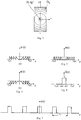
- Fig. 1 shows the domain where the optical element is defined
- Fig. 2 shows the scheme of the partition of the optical element into elementary areas Q ij
- Fig. 3 shows the structure of the axial Fresnel lens in area Q ij
- Fig. 4 shows the phase functions ⁇ + (y) and ⁇ - (y) of the axial Fresnel lenses
- Fig. 5 shows the binary version of the phase function ⁇ (y) of the axial Fresnel lens
- Fig. 6 shows the plot of function ⁇ (y)
- Fig. 7 shows the plot of function ⁇ (y);
- Fig. 1 shows the domain where the optical element is defined
- Fig. 2 shows the scheme of the partition of the optical element into elementary areas Q ij
- Fig. 3 shows the structure of the axial Fresnel lens in area Q ij
- Fig. 4 shows the phase functions ⁇ + (y) and ⁇ - (y) of the axial Fresnel lenses
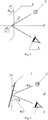
- Fig. 8 shows schematically the mutual positions of the light source and the observer with respect to the microoptical system
- Fig. 9 shows the scheme of observation of the microoptical system in the case where the optical element is tilted up/down by angle ⁇
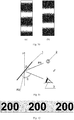
- Fig. 10 shows the variants of the images formed by the microoptical system as per claims 1 and 2 for two different diffraction angles smaller than 60°
- Fig. 11 shows the scheme of observation of the microoptical system in the case of diffraction angles ⁇ > 60
- Fig. 12 shows the variant of the color image seen by the observer at diffraction angles greater than 60°
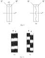
- Fig. 13 shows the variants of the partitioning of the optical element Q into areas Q 1 Q 2 ;
- Fig. 9 shows schematically the mutual positions of the light source and the observer with respect to the microoptical system
- Fig. 9 shows the scheme of observation of the microoptical system in the case where the optical element is tilted up/down by angle ⁇
- Fig. 10 shows
- Fig. 14 shows variants of images formed by the microoptical system as per claims 3 - 6 at diffraction angles smaller than 60°;
- Fig. 15 shows a fragment of the structure of the microrelief of the microoptical system as per claim 4;
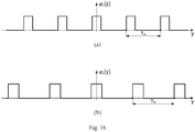
- Fig. 16 shows the plots of functions ⁇ 1 (y) and ⁇ 2 (y) as per claims 5 and 6;
- Fig. 17 shows a fragment of the structure of the microrelief of the microoptical system as per claim 6;
- Fig. 18 shows an example of the partition of a 4.5 mm wide security thread into areas Q 1 and Q 2 ;
- Fig. 19 shows images seen by the observer at diffraction angles smaller than 60° (a) and greater than 60° (b) for a 4.5 mm wide security thread.
- the microoptical system claimed in this invention is a flat optical phase element consisting of multilevel diffraction elements - axial Fresnel lenses and diffraction gratings.
- Fig. 1 shows area Q where the optical element as per claims 1-6 is defined. Area Q has the form of an L x ⁇ L y rectangle centered on the origin of the Cartesian coordinate system Oxy.
- Fig. 2 shows the partition scheme of the optical element into elementary areas Q ij . The center of each elementary area Q ij is located at the point with the coordinates (x i ,y j ). The sizes of the elementary areas do not exceed 250 microns.
- the rectangle is elongate along the Oy axis, i.e., L y >L x .
- the microoptical system is formed using axial Fresnel lenses.
- Fig. 3 shows schematically the mutual positions of the Fresnel lenses in elementary areas Q ij .
- the solid lines show the contours of the phase function.
- We use the functions ⁇ + (x,y) and ⁇ - (x,y) defined by the formula ⁇ (x,y) C ⁇ (x 2 +y 2 ), where C is the given parameter as the phase functions for concave and convex lenses, respectively.
- the phase functions shown in Fig. 4 correspond to multilevel phase elements ( A.V. Goncharsky and A.A. Goncharsky, Computer Optics and Computer Holography, Moscow: Moscow University Press, 2004, ISBN 5-211-04902-0 ). This is the preferred variant for the formation of microoptical systems in accordance with the claimed invention.
- Fig. 5 shows the variant of a binary phase element. Unlike the phase function of a multilevel flat optical element the phase function of a binary optical element takes only two values. Only multilevel axial Fresnel lenses with a parabolic function are used in all claims.
- Phase function ⁇ (x,y) uniquely determines the microrelief of the flat optical element in area Q. Given the phase function it is possible to compute the depth of the microrelief at each point (x, y) of area Q.
- Fig. 8 shows schematically the arrangement of microoptical system 1 relative to the Oxy plane.
- the microoptical system is illuminated by point light source 2 located in the Oyz plane.
- the optical element may turn about the Ox axis by angle ⁇ . Let us denote the turn angle of the optical element about the Oy axis as ⁇ .
- the eye of the observer is located in the Oyz plane.
- the optical element is turned up/down about the Ox axis and left/right about the Oy axis.
- Fig. 9 shows the scheme of observation for microoptical system 1 in the range of diffraction angles smaller than 60°.
- Diffraction angle ⁇ is measured as the angle between the zero order of diffraction denoted as ray R2 in Fig. 9 and the direction toward observer's eye 3.
- the direction of ray R2 coincides with the direction of the ray from light source 2 reflected from the optical element (ray R1) if the phase function of the optical element is constant, i.e., if the optical element is a mirror.
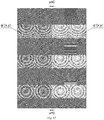
- Fig. 10 shows two images seen by the observer at different angles ⁇ smaller than 60°.
- the image at diffraction angles smaller than 60° is formed via fragments of axial Fresnel lenses with a parabolic phase function.
- the size of the outermost Fresnel zones is an important parameter characterizing flat axial Fresnel lenses. In the preferred version of the invention the size of the outermost Fresnel zones does not exceed 1.2 microns. Because the size of rectangular Fresnel lenses does not exceed 250 microns and the size of the outermost Fresnel zones does not exceed 1.2 microns the lens produces a horizontally wide directivity diagram of the light reflected from the microoptical system.
- Fresnel lenses form an image consisting of horizontal black and white stripes, which does not change if the optical element is turned about the Oy axis left/right by angles ⁇ lying within the ⁇ 15° interval.
- the kinematic effect consists in the motion of black-and-white stripes when the microoptical system is tilted up/down by angles within the ⁇ 30° interval.
- Fresnel lenses cannot be seen by human eye because their size does not exceed 250 microns, which makes the claimed invention essentially different from the prototype where the diameter of Fresnel lenses in the preferred variant ranges from 0.5 to 1.5 mm. the chosen parameters make it possible to form an image, which, unlike that of the prototype, does not consist of isolated points but has the form of solid bright black and white strips, which move in the vertical direction when the optical element is tilted up/down.
- An essential difference from the prototype is that the claimed microoptical system uses multilevel optical elements as Fresnel lenses. It because of the use of multilevel optical elements that the behavior of the motion of stripes does not change across the zero order of diffraction, which corresponds to the transition from positive angles of the tilt of the optical element, ⁇ > 0, to negative angles ⁇ ⁇ 0.
- the microoptical system as per claim 2 differs from the microoptical system as per claim 1 in that area Q of the optical element where the phase function ⁇ (x,y) equals zero is filled with diffraction gratings of various orientations and various periods, which do not exceed 0.6 microns.
- area Q of the optical element where the phase function ⁇ (x,y) equals zero is filled with diffraction gratings of various orientations and various periods, which do not exceed 0.6 microns.
- Fig. 11 shows the observation scheme of the microoptical system art large diffraction angles ⁇ > 60°.
- diffraction angle ⁇ is measured as the angle between the direction toward the observer 3 and the zero order of diffraction R2.
- Figs. 9 and 11 differ only by the value of angle ⁇ .
- Large tilts of the optical element correspond to large angles ⁇ and hence to large diffraction angles ⁇ .
- the parameters of the microrelief of the microoptical system are chosen so that at diffraction angles greater than 60° the image is formed by diffraction gratings.
- the sizes of diffraction gratings do not exceed 200 microns and therefore grating fragments cannot be seen by the observer.
- Fig. 12 shows a variant of such a color image in representative colors. Black and gray correspond to green and red color, respectively.
- area Q is subdivided inti two areas Q 1 and Q 2 as shown in Fig. 13 .
- the boundary between areas Q 1 and Q 2 may have the form of both a straight line as shown in Fig. 13(a) and of an undulating line as shown in Fig. 13(b) .
- the microoptical system as per claim 3 has optical-element area subdivided into areas Q 1 and Q 2 .
- phase functions ⁇ + ij (x,y) in area Q 1 and ⁇ - ij (x,y) in area Q 2 differ only in sign.
- Functions ⁇ (y) coincide in areas Q 1 and Q 2 .
- Function ⁇ (y) which is defined over the entire area Q, is the periodic extension of function ⁇ (y) defined on the interval lyl ⁇ T ⁇ /2.
- Function ⁇ (y) equals 1 if lyl ⁇ ⁇ /2 and equals 0 if
- Fig. 14 shows the variants of the images of the microoptical system as per claims 3 - 6 at various diffraction angles smaller than 60°.
- the microoptical system as per claim 4 differs in that area Q of the optical element where phase function ⁇ (x,y) equals zero is filled with diffraction gratings of various orientations and various periods, which do not exceed 0.6 microns.
- Fig. 15 shows a fragment of the microstructure of the microoptical system as per claim 4.
- the presented fragment has the size of 400 microns along the Ox axis and 608.4 microns along the Oy axis.
- the depth of the microrelief at point (x,y) is proportional to darkening at that point.
- the microoptical system as per claim 5 has area Q of the optical element subdivided into areas Q 1 and Q 2 . Each of the areas Q 1 and Q 2 is subdivided into elementary areas Q 1 ij and Q 2 ij .
- phase functions ⁇ ij (x,y) in areas Q 1 and Q 2 coincide.
- Functions ⁇ 1 (y) and ⁇ 2 (y) in areas Q 1 and Q 2 are different.
- Functions ⁇ 1 (y) and ⁇ 2 (y) are chosen as follows.
- Function ⁇ 1 (y) defined in area Q 1 is the periodic extension of function ⁇ 1 (y) defined on the
- Function ⁇ 2 (y) defined in area Q 2 is the periodic extension of function ⁇ 2 ( Y ) defined on the
- the parameters T ⁇ 1 , T ⁇ 2 , ⁇ 1' and ⁇ 2 are given parameters such that ⁇ 1 /T ⁇ 1 ⁇ 1 ⁇ 2, ⁇ 2 /T ⁇ 2 ⁇ 1 ⁇ 2.
- T ⁇ 1 ⁇ T ⁇ ⁇ T ⁇ 2 or T ⁇ 2 ⁇ T ⁇ ⁇ T ⁇ 1 - is satisfied.
- Fig. 16 shows plots of functions ⁇ 1 (y) and ⁇ 2 (y).
- Fig. 17 shows a fragment of the microstructure of the microoptical system as per claim 6.
- the phase functions ⁇ ij (x,y) in areas Q 1 and Q 2 coincide, but functions ⁇ 1 (y) and ⁇ 2 (y) are different.
- the depth of the microrelief at point (x,y) is proportional to darkening at that point.
- Fig. 18 shows another variant of the partition of the security thread into areas Q 1 and Q 2 . Such a variant can be efficiently used if the width of the thread is greater than 4 mm.
- Fig. 19 shows the images seen by the observer at diffraction angles smaller than 60° (a) and greater than 60° (b) for a 4.5 mm wide security thread. The effect of the motion of black and white stripes at diffraction angles smaller than 60° is easy to control visually. At diffraction angles greater than 60° the observer sees another color image over the entire area of the optical element.
- Microoptical systems proposed in the claimed invention are made using electron-beam technology. Electron-beam lithography provides very high resolution (0.1 microns or better) and ensures the required accuracy of the production of the microrelief - about 20 nanometers. Currently, several hundred companies produce security holograms. Practically all these companies use optical technologies to record the originals of security features. Optical methods of the synthesis of originals include the technologies KineMax, Kinegram, etc. ( van Renesse, Rudolf L, Optical Document Security, 3rd ed.
- microoptical systems were made in the form of a 2 mm, 3 mm and 4.5 mm wide reflecting holographic thread for protecting bank notes and securities.
- the size of Q ij rectangles was about 100x200 microns.
- the minimal size of the outermost Fresnel zone is of about 1.2 microns.
- the number of Fresnel zones is on the order of 50.
- the size of the central zone is about 10 microns.
- Figs. 9 and 11 show the scheme of observation of the microoptical system at diffraction angles ⁇ ⁇ 60° and ⁇ > 60°, respectively.
- diffraction gratings with the periods of 0.45 and 0.55 micron were used.
- the size of the fragments pf diffraction gratings is 20 microns.
- a microoptical system was made in the form of a 2 mm wide holographic security thread.
- Fig. 2 shows the scheme of the partitioning of the optical element into elementary areas Q ij .
- the phase function ⁇ + ij (x,y) was used for the formation of Fresnel lenses.
- Fig. 12 shows the color image seen at large diffraction angles (greater than 60°).
- Fig. 10 shows the monochrome image seen at diffraction angles smaller than 60°.
- the monochrome image consists of black and white stripes, which move when the holographic thread is tilted up/down.
- a microoptical system was made in the form of a 3 mm wide holographic security thread.
- Fig. 2 shows the scheme of the partitioning of the optical element into areas Q 1 and Q 2 .
- the phase functions ⁇ + ij (x,y) and ⁇ - ij (x,y) were used for areas Q 1 and Q 2 , respectively.
- Fig. 13(a) shows the color image seen at large diffraction angles (greater than 60°).
- Fig. 12 shows the monochrome image seen at diffraction angles smaller than 60°.
- the monochrome image consists of black and white stripes, which move toward each other when the holographic thread is tilted up/down.
- a microoptical system was made in the form of a 3 mm wide holographic security thread.
- Fig. 13(b) shows the scheme of the partitioning of the optical element into areas Q 1 and Q 2 .
- the phase functions ⁇ + ij (x,y) was used for areas Q 1 and Q 2 , respectively.
- Fig. 12 shows the color image seen at large diffraction angles (greater than 60°).
- Fig. 14 shows the monochrome image seen at diffraction angles smaller than 60°.
- the monochrome image consists of black and white stripes, which move toward each other when the holographic thread is tilted up/down.
- a microoptical system was made in the form of a 4.5 mm wide holographic security thread.
- Fig. 18 shows the scheme of the partitioning of the optical element Q into areas Q 1 and Q 2 .
- the phase functions ⁇ + ij (x,y) and ⁇ - ij (x,y) were used for areas Q 1 and Q 2 , respectively.
- Fig. 19(b) shows the color image seen at large diffraction angles greater than 60°.
- Fig. 19(a) shows the monochrome image seen at diffraction angles smaller than 60°.
- Visual images are easy to control.
- Microoptical systems are securely protected against counterfeit.
- Microoptical systems claimed in the invention can be used to protect bank notes, securities, documents, excise stamps, and plastic cards.
Landscapes
- Physics & Mathematics (AREA)
- General Physics & Mathematics (AREA)
- Optics & Photonics (AREA)
- Engineering & Computer Science (AREA)
- Health & Medical Sciences (AREA)
- Computer Security & Cryptography (AREA)
- General Health & Medical Sciences (AREA)
- Toxicology (AREA)
- Business, Economics & Management (AREA)
- Accounting & Taxation (AREA)
- Finance (AREA)
- Computer Vision & Pattern Recognition (AREA)
- Diffracting Gratings Or Hologram Optical Elements (AREA)
- Inspection Of Paper Currency And Valuable Securities (AREA)
- Credit Cards Or The Like (AREA)
Applications Claiming Priority (2)
| Application Number | Priority Date | Filing Date | Title |
|---|---|---|---|
| EA201700240A EA030058B1 (ru) | 2017-03-15 | 2017-03-15 | Микрооптическая система формирования визуальных изображений с кинематическими эффектами движения |
| PCT/RU2018/000156 WO2018169450A2 (ru) | 2017-03-15 | 2018-03-13 | Микрооптическая система формирования визуальных изображений с кинематическими эффектами движения |
Publications (3)
| Publication Number | Publication Date |
|---|---|
| EP3598204A2 true EP3598204A2 (de) | 2020-01-22 |
| EP3598204A4 EP3598204A4 (de) | 2020-12-16 |
| EP3598204B1 EP3598204B1 (de) | 2022-02-09 |
Family
ID=61244311
Family Applications (1)
| Application Number | Title | Priority Date | Filing Date |
|---|---|---|---|
| EP18768308.1A Active EP3598204B1 (de) | 2017-03-15 | 2018-03-13 | Mikrooptisches system zur herstellung visueller bilder mit kinematischen bewegungseffekten |
Country Status (3)
| Country | Link |
|---|---|
| EP (1) | EP3598204B1 (de) |
| EA (1) | EA030058B1 (de) |
| WO (1) | WO2018169450A2 (de) |
Cited By (2)
| Publication number | Priority date | Publication date | Assignee | Title |
|---|---|---|---|---|
| WO2023281123A1 (fr) | 2021-07-09 | 2023-01-12 | Surys | Composants optiques de sécurité, fabrication de tels composants et documents sécurisés équipés de tels composants |
| EP4484174A1 (de) * | 2023-06-30 | 2025-01-01 | Joanneum Research Forschungsgesellschaft mbH | Mikrostruktur mit optischen effekten |
Families Citing this family (2)
| Publication number | Priority date | Publication date | Assignee | Title |
|---|---|---|---|---|
| EA034156B1 (ru) * | 2019-02-20 | 2020-01-13 | Общество С Ограниченной Ответственностью "Центр Компьютерной Голографии" | Микрооптическая система формирования визуальных изображений с кинематическими эффектами движения |
| CN114919311A (zh) * | 2021-02-03 | 2022-08-19 | 中钞特种防伪科技有限公司 | 一种防伪元件 |
Family Cites Families (11)
| Publication number | Priority date | Publication date | Assignee | Title |
|---|---|---|---|---|
| DE4436192C1 (de) * | 1994-10-11 | 1996-03-21 | Kurz Leonhard Fa | Strukturanordnung, insbesondere für ein Sicherheitselement |
| ES2654209T5 (es) * | 2005-05-18 | 2021-09-30 | Visual Physics Llc | Sistema de presentación de imágenes y de seguridad micro-óptico |
| DE102007029204A1 (de) * | 2007-06-25 | 2009-01-08 | Giesecke & Devrient Gmbh | Sicherheitselement |
| EA017394B1 (ru) | 2010-03-09 | 2012-12-28 | Ооо "Центр Компьютерной Голографии" | Микрооптическая система формирования визуальных изображений |
| RU2430836C1 (ru) * | 2010-07-29 | 2011-10-10 | Федеральное Государственное Унитарное Предприятие "Гознак" (Фгуп "Гознак") | Многослойный защитный элемент с переменным оптическим эффектом и защищенный от подделки документ |
| RU127208U1 (ru) | 2012-10-11 | 2013-04-20 | Общество С Ограниченной Ответственностью "Центр Компьютерной Голографии" | Микрооптическая система формирования визуальных изображений |
| EA026552B1 (ru) * | 2014-03-20 | 2017-04-28 | Общество С Ограниченной Ответственностью "Центр Компьютерной Голографии" | Микрооптическая система формирования динамических визуальных изображений |
| RU149690U1 (ru) * | 2014-03-25 | 2015-01-20 | Общество С Ограниченной Ответственностью "Центр Компьютерной Голографии" | Микрооптическая система формирования визуальных изображений |
| FR3019496A1 (fr) * | 2014-04-07 | 2015-10-09 | Hologram Ind | Composant optique de securite a effet reflectif, fabrication d'un tel composant et document securise equipe d'un tel composant |
| TW201605655A (zh) * | 2014-07-29 | 2016-02-16 | 西克帕控股有限公司 | 用於由磁場產生裝置產生凹形磁力線所製成之光學效果層之場內硬化之方法 |
| DE102016007784A1 (de) * | 2016-06-24 | 2017-12-28 | Giesecke+Devrient Currency Technology Gmbh | Optisch variables Sicherheitselement |
-
2017
- 2017-03-15 EA EA201700240A patent/EA030058B1/ru not_active IP Right Cessation
-
2018
- 2018-03-13 EP EP18768308.1A patent/EP3598204B1/de active Active
- 2018-03-13 WO PCT/RU2018/000156 patent/WO2018169450A2/ru not_active Ceased
Cited By (5)
| Publication number | Priority date | Publication date | Assignee | Title |
|---|---|---|---|---|
| WO2023281123A1 (fr) | 2021-07-09 | 2023-01-12 | Surys | Composants optiques de sécurité, fabrication de tels composants et documents sécurisés équipés de tels composants |
| FR3124980A1 (fr) * | 2021-07-09 | 2023-01-13 | Surys | Composants optiques de sécurité, fabrication de tels composants et documents sécurisés équipés de tels composants |
| US12246553B2 (en) | 2021-07-09 | 2025-03-11 | Surys | Optical security components, manufacture of such components and secure documents equipped with such components |
| EP4484174A1 (de) * | 2023-06-30 | 2025-01-01 | Joanneum Research Forschungsgesellschaft mbH | Mikrostruktur mit optischen effekten |
| WO2025003285A1 (de) * | 2023-06-30 | 2025-01-02 | Joanneum Research Forschungsgesellschaft Mbh | Mikrostruktur mit optischen effekten |
Also Published As
| Publication number | Publication date |
|---|---|
| EP3598204B1 (de) | 2022-02-09 |
| EA201700240A2 (ru) | 2018-02-28 |
| EA030058B1 (ru) | 2018-06-29 |
| EA201700240A3 (ru) | 2018-03-30 |
| WO2018169450A2 (ru) | 2018-09-20 |
| WO2018169450A3 (ru) | 2019-01-31 |
| EP3598204A4 (de) | 2020-12-16 |
Similar Documents
| Publication | Publication Date | Title |
|---|---|---|
| RU2591089C2 (ru) | Защитный элемент с оптически переменным поверхностным узором | |
| US6924934B2 (en) | Diffractive safety element | |
| CN101711203B (zh) | 具有放大的三维摩尔图像的安全元件 | |
| EP3598204B1 (de) | Mikrooptisches system zur herstellung visueller bilder mit kinematischen bewegungseffekten | |
| CN103260893B (zh) | 具有布置在基底上的光学元件的、用于产生悬浮在基底上方或下方的光斑图像的显示元件 | |
| US10625532B2 (en) | Security element | |
| US10639925B2 (en) | Visually variable security element | |
| CN105437822B (zh) | 具有反射性的面区域的光学可变的安全元件 | |
| EP2600332B1 (de) | Mehrschichtiges sicherheitselement mit veränderlichem optischem effekt und fälschungssicheres dokument | |
| AU2016101590A4 (en) | A 3d micromirror device | |
| DE10129939A1 (de) | Optisch variables Flächenmuster | |
| WO2011110185A1 (ru) | Микрооптическая система формирования визуальных изображений | |
| RU127208U1 (ru) | Микрооптическая система формирования визуальных изображений | |
| EP3929001A1 (de) | Mikrooptisches system zur formung visueller bilder | |
| RU149690U1 (ru) | Микрооптическая система формирования визуальных изображений | |
| JP6338315B2 (ja) | 表示体 | |
| AU2009324136A1 (en) | Optical device and method of manufacture | |
| EP2955564B1 (de) | Optisch variables element | |
| EP4067107B1 (de) | Verfahren zum synthetisieren planarer diffraktiver optischer elemente | |
| RU190048U1 (ru) | Микрооптическая система для формирования 2D изображений | |
| EP3842252B1 (de) | Mikrooptisches system zur erzeugung eines 3d-bildes in der nullten beugungsordnung | |
| RU152465U1 (ru) | Микрооптическая система формирования изображений для визуального контроля подлинности изделий | |
| RU140190U1 (ru) | Микрооптическая система формирования изображений для визуального и инструментального контроля | |
| JP2023107332A (ja) | 光輝性動画模様形成体 | |
| RU212103U1 (ru) | Микрооптическое устройство формирования изображений для визуального контроля |
Legal Events
| Date | Code | Title | Description |
|---|---|---|---|
| STAA | Information on the status of an ep patent application or granted ep patent |
Free format text: STATUS: THE INTERNATIONAL PUBLICATION HAS BEEN MADE |
|
| PUAI | Public reference made under article 153(3) epc to a published international application that has entered the european phase |
Free format text: ORIGINAL CODE: 0009012 |
|
| STAA | Information on the status of an ep patent application or granted ep patent |
Free format text: STATUS: REQUEST FOR EXAMINATION WAS MADE |
|
| 17P | Request for examination filed |
Effective date: 20190919 |
|
| AK | Designated contracting states |
Kind code of ref document: A2 Designated state(s): AL AT BE BG CH CY CZ DE DK EE ES FI FR GB GR HR HU IE IS IT LI LT LU LV MC MK MT NL NO PL PT RO RS SE SI SK SM TR |
|
| A4 | Supplementary search report drawn up and despatched |
Effective date: 20201112 |
|
| RIC1 | Information provided on ipc code assigned before grant |
Ipc: B42D 25/328 20140101ALI20201106BHEP Ipc: B42D 25/30 20140101ALI20201106BHEP Ipc: G03H 1/22 20060101ALN20201106BHEP Ipc: G02B 3/08 20060101ALI20201106BHEP Ipc: G02B 5/18 20060101ALI20201106BHEP Ipc: B42D 25/355 20140101ALI20201106BHEP Ipc: B42D 25/29 20140101ALI20201106BHEP Ipc: B42D 25/324 20140101ALI20201106BHEP Ipc: G07D 7/00 20160101ALI20201106BHEP Ipc: G02B 27/42 20060101AFI20201106BHEP Ipc: G02B 3/00 20060101ALI20201106BHEP |
|
| RIC1 | Information provided on ipc code assigned before grant |
Ipc: G03H 1/22 20060101ALN20211013BHEP Ipc: G07D 7/12 20160101ALI20211013BHEP Ipc: G07D 7/207 20160101ALI20211013BHEP Ipc: G03H 1/00 20060101ALI20211013BHEP Ipc: B42D 25/355 20140101ALI20211013BHEP Ipc: B42D 25/29 20140101ALI20211013BHEP Ipc: B42D 25/324 20140101ALI20211013BHEP Ipc: G07D 7/00 20160101ALI20211013BHEP Ipc: G02B 5/18 20060101ALI20211013BHEP Ipc: G02B 3/08 20060101ALI20211013BHEP Ipc: B42D 25/30 20140101ALI20211013BHEP Ipc: G02B 3/00 20060101ALI20211013BHEP Ipc: B42D 25/328 20140101ALI20211013BHEP Ipc: G02B 27/42 20060101AFI20211013BHEP |
|
| GRAP | Despatch of communication of intention to grant a patent |
Free format text: ORIGINAL CODE: EPIDOSNIGR1 |
|
| STAA | Information on the status of an ep patent application or granted ep patent |
Free format text: STATUS: GRANT OF PATENT IS INTENDED |
|
| RIC1 | Information provided on ipc code assigned before grant |
Ipc: G03H 1/22 20060101ALN20211109BHEP Ipc: G07D 7/12 20160101ALI20211109BHEP Ipc: G07D 7/207 20160101ALI20211109BHEP Ipc: G03H 1/00 20060101ALI20211109BHEP Ipc: B42D 25/355 20140101ALI20211109BHEP Ipc: B42D 25/29 20140101ALI20211109BHEP Ipc: B42D 25/324 20140101ALI20211109BHEP Ipc: G07D 7/00 20160101ALI20211109BHEP Ipc: G02B 5/18 20060101ALI20211109BHEP Ipc: G02B 3/08 20060101ALI20211109BHEP Ipc: B42D 25/30 20140101ALI20211109BHEP Ipc: G02B 3/00 20060101ALI20211109BHEP Ipc: B42D 25/328 20140101ALI20211109BHEP Ipc: G02B 27/42 20060101AFI20211109BHEP |
|
| INTG | Intention to grant announced |
Effective date: 20211125 |
|
| GRAS | Grant fee paid |
Free format text: ORIGINAL CODE: EPIDOSNIGR3 |
|
| GRAA | (expected) grant |
Free format text: ORIGINAL CODE: 0009210 |
|
| STAA | Information on the status of an ep patent application or granted ep patent |
Free format text: STATUS: THE PATENT HAS BEEN GRANTED |
|
| AK | Designated contracting states |
Kind code of ref document: B1 Designated state(s): AL AT BE BG CH CY CZ DE DK EE ES FI FR GB GR HR HU IE IS IT LI LT LU LV MC MK MT NL NO PL PT RO RS SE SI SK SM TR |
|
| REG | Reference to a national code |
Ref country code: GB Ref legal event code: FG4D |
|
| REG | Reference to a national code |
Ref country code: CH Ref legal event code: EP Ref country code: AT Ref legal event code: REF Ref document number: 1467864 Country of ref document: AT Kind code of ref document: T Effective date: 20220215 |
|
| REG | Reference to a national code |
Ref country code: IE Ref legal event code: FG4D |
|
| REG | Reference to a national code |
Ref country code: DE Ref legal event code: R096 Ref document number: 602018030609 Country of ref document: DE |
|
| REG | Reference to a national code |
Ref country code: LT Ref legal event code: MG9D |
|
| REG | Reference to a national code |
Ref country code: NL Ref legal event code: MP Effective date: 20220209 |
|
| REG | Reference to a national code |
Ref country code: AT Ref legal event code: MK05 Ref document number: 1467864 Country of ref document: AT Kind code of ref document: T Effective date: 20220209 |
|
| PG25 | Lapsed in a contracting state [announced via postgrant information from national office to epo] |
Ref country code: SE Free format text: LAPSE BECAUSE OF FAILURE TO SUBMIT A TRANSLATION OF THE DESCRIPTION OR TO PAY THE FEE WITHIN THE PRESCRIBED TIME-LIMIT Effective date: 20220209 Ref country code: RS Free format text: LAPSE BECAUSE OF FAILURE TO SUBMIT A TRANSLATION OF THE DESCRIPTION OR TO PAY THE FEE WITHIN THE PRESCRIBED TIME-LIMIT Effective date: 20220209 Ref country code: PT Free format text: LAPSE BECAUSE OF FAILURE TO SUBMIT A TRANSLATION OF THE DESCRIPTION OR TO PAY THE FEE WITHIN THE PRESCRIBED TIME-LIMIT Effective date: 20220609 Ref country code: NO Free format text: LAPSE BECAUSE OF FAILURE TO SUBMIT A TRANSLATION OF THE DESCRIPTION OR TO PAY THE FEE WITHIN THE PRESCRIBED TIME-LIMIT Effective date: 20220509 Ref country code: NL Free format text: LAPSE BECAUSE OF FAILURE TO SUBMIT A TRANSLATION OF THE DESCRIPTION OR TO PAY THE FEE WITHIN THE PRESCRIBED TIME-LIMIT Effective date: 20220209 Ref country code: LT Free format text: LAPSE BECAUSE OF FAILURE TO SUBMIT A TRANSLATION OF THE DESCRIPTION OR TO PAY THE FEE WITHIN THE PRESCRIBED TIME-LIMIT Effective date: 20220209 Ref country code: HR Free format text: LAPSE BECAUSE OF FAILURE TO SUBMIT A TRANSLATION OF THE DESCRIPTION OR TO PAY THE FEE WITHIN THE PRESCRIBED TIME-LIMIT Effective date: 20220209 Ref country code: ES Free format text: LAPSE BECAUSE OF FAILURE TO SUBMIT A TRANSLATION OF THE DESCRIPTION OR TO PAY THE FEE WITHIN THE PRESCRIBED TIME-LIMIT Effective date: 20220209 Ref country code: BG Free format text: LAPSE BECAUSE OF FAILURE TO SUBMIT A TRANSLATION OF THE DESCRIPTION OR TO PAY THE FEE WITHIN THE PRESCRIBED TIME-LIMIT Effective date: 20220509 |
|
| PG25 | Lapsed in a contracting state [announced via postgrant information from national office to epo] |
Ref country code: PL Free format text: LAPSE BECAUSE OF FAILURE TO SUBMIT A TRANSLATION OF THE DESCRIPTION OR TO PAY THE FEE WITHIN THE PRESCRIBED TIME-LIMIT Effective date: 20220209 Ref country code: LV Free format text: LAPSE BECAUSE OF FAILURE TO SUBMIT A TRANSLATION OF THE DESCRIPTION OR TO PAY THE FEE WITHIN THE PRESCRIBED TIME-LIMIT Effective date: 20220209 Ref country code: GR Free format text: LAPSE BECAUSE OF FAILURE TO SUBMIT A TRANSLATION OF THE DESCRIPTION OR TO PAY THE FEE WITHIN THE PRESCRIBED TIME-LIMIT Effective date: 20220510 Ref country code: FI Free format text: LAPSE BECAUSE OF FAILURE TO SUBMIT A TRANSLATION OF THE DESCRIPTION OR TO PAY THE FEE WITHIN THE PRESCRIBED TIME-LIMIT Effective date: 20220209 Ref country code: AT Free format text: LAPSE BECAUSE OF FAILURE TO SUBMIT A TRANSLATION OF THE DESCRIPTION OR TO PAY THE FEE WITHIN THE PRESCRIBED TIME-LIMIT Effective date: 20220209 |
|
| PG25 | Lapsed in a contracting state [announced via postgrant information from national office to epo] |
Ref country code: IS Free format text: LAPSE BECAUSE OF FAILURE TO SUBMIT A TRANSLATION OF THE DESCRIPTION OR TO PAY THE FEE WITHIN THE PRESCRIBED TIME-LIMIT Effective date: 20220609 |
|
| PG25 | Lapsed in a contracting state [announced via postgrant information from national office to epo] |
Ref country code: SM Free format text: LAPSE BECAUSE OF FAILURE TO SUBMIT A TRANSLATION OF THE DESCRIPTION OR TO PAY THE FEE WITHIN THE PRESCRIBED TIME-LIMIT Effective date: 20220209 Ref country code: SK Free format text: LAPSE BECAUSE OF FAILURE TO SUBMIT A TRANSLATION OF THE DESCRIPTION OR TO PAY THE FEE WITHIN THE PRESCRIBED TIME-LIMIT Effective date: 20220209 Ref country code: RO Free format text: LAPSE BECAUSE OF FAILURE TO SUBMIT A TRANSLATION OF THE DESCRIPTION OR TO PAY THE FEE WITHIN THE PRESCRIBED TIME-LIMIT Effective date: 20220209 Ref country code: EE Free format text: LAPSE BECAUSE OF FAILURE TO SUBMIT A TRANSLATION OF THE DESCRIPTION OR TO PAY THE FEE WITHIN THE PRESCRIBED TIME-LIMIT Effective date: 20220209 Ref country code: DK Free format text: LAPSE BECAUSE OF FAILURE TO SUBMIT A TRANSLATION OF THE DESCRIPTION OR TO PAY THE FEE WITHIN THE PRESCRIBED TIME-LIMIT Effective date: 20220209 Ref country code: CZ Free format text: LAPSE BECAUSE OF FAILURE TO SUBMIT A TRANSLATION OF THE DESCRIPTION OR TO PAY THE FEE WITHIN THE PRESCRIBED TIME-LIMIT Effective date: 20220209 |
|
| REG | Reference to a national code |
Ref country code: CH Ref legal event code: PL |
|
| REG | Reference to a national code |
Ref country code: DE Ref legal event code: R097 Ref document number: 602018030609 Country of ref document: DE |
|
| PG25 | Lapsed in a contracting state [announced via postgrant information from national office to epo] |
Ref country code: MC Free format text: LAPSE BECAUSE OF FAILURE TO SUBMIT A TRANSLATION OF THE DESCRIPTION OR TO PAY THE FEE WITHIN THE PRESCRIBED TIME-LIMIT Effective date: 20220209 Ref country code: AL Free format text: LAPSE BECAUSE OF FAILURE TO SUBMIT A TRANSLATION OF THE DESCRIPTION OR TO PAY THE FEE WITHIN THE PRESCRIBED TIME-LIMIT Effective date: 20220209 |
|
| REG | Reference to a national code |
Ref country code: BE Ref legal event code: MM Effective date: 20220331 |
|
| PLBE | No opposition filed within time limit |
Free format text: ORIGINAL CODE: 0009261 |
|
| STAA | Information on the status of an ep patent application or granted ep patent |
Free format text: STATUS: NO OPPOSITION FILED WITHIN TIME LIMIT |
|
| 26N | No opposition filed |
Effective date: 20221110 |
|
| PG25 | Lapsed in a contracting state [announced via postgrant information from national office to epo] |
Ref country code: LU Free format text: LAPSE BECAUSE OF NON-PAYMENT OF DUE FEES Effective date: 20220313 Ref country code: LI Free format text: LAPSE BECAUSE OF NON-PAYMENT OF DUE FEES Effective date: 20220331 Ref country code: IE Free format text: LAPSE BECAUSE OF NON-PAYMENT OF DUE FEES Effective date: 20220313 Ref country code: CH Free format text: LAPSE BECAUSE OF NON-PAYMENT OF DUE FEES Effective date: 20220331 |
|
| PG25 | Lapsed in a contracting state [announced via postgrant information from national office to epo] |
Ref country code: SI Free format text: LAPSE BECAUSE OF FAILURE TO SUBMIT A TRANSLATION OF THE DESCRIPTION OR TO PAY THE FEE WITHIN THE PRESCRIBED TIME-LIMIT Effective date: 20220209 Ref country code: BE Free format text: LAPSE BECAUSE OF NON-PAYMENT OF DUE FEES Effective date: 20220331 |
|
| PG25 | Lapsed in a contracting state [announced via postgrant information from national office to epo] |
Ref country code: IT Free format text: LAPSE BECAUSE OF FAILURE TO SUBMIT A TRANSLATION OF THE DESCRIPTION OR TO PAY THE FEE WITHIN THE PRESCRIBED TIME-LIMIT Effective date: 20220209 |
|
| PG25 | Lapsed in a contracting state [announced via postgrant information from national office to epo] |
Ref country code: MK Free format text: LAPSE BECAUSE OF FAILURE TO SUBMIT A TRANSLATION OF THE DESCRIPTION OR TO PAY THE FEE WITHIN THE PRESCRIBED TIME-LIMIT Effective date: 20220209 Ref country code: CY Free format text: LAPSE BECAUSE OF FAILURE TO SUBMIT A TRANSLATION OF THE DESCRIPTION OR TO PAY THE FEE WITHIN THE PRESCRIBED TIME-LIMIT Effective date: 20220209 |
|
| PG25 | Lapsed in a contracting state [announced via postgrant information from national office to epo] |
Ref country code: HU Free format text: LAPSE BECAUSE OF FAILURE TO SUBMIT A TRANSLATION OF THE DESCRIPTION OR TO PAY THE FEE WITHIN THE PRESCRIBED TIME-LIMIT; INVALID AB INITIO Effective date: 20180313 |
|
| PG25 | Lapsed in a contracting state [announced via postgrant information from national office to epo] |
Ref country code: TR Free format text: LAPSE BECAUSE OF FAILURE TO SUBMIT A TRANSLATION OF THE DESCRIPTION OR TO PAY THE FEE WITHIN THE PRESCRIBED TIME-LIMIT Effective date: 20220209 |
|
| PG25 | Lapsed in a contracting state [announced via postgrant information from national office to epo] |
Ref country code: MT Free format text: LAPSE BECAUSE OF FAILURE TO SUBMIT A TRANSLATION OF THE DESCRIPTION OR TO PAY THE FEE WITHIN THE PRESCRIBED TIME-LIMIT Effective date: 20220209 |
|
| PGFP | Annual fee paid to national office [announced via postgrant information from national office to epo] |
Ref country code: GB Payment date: 20260107 Year of fee payment: 9 |
|
| PGFP | Annual fee paid to national office [announced via postgrant information from national office to epo] |
Ref country code: DE Payment date: 20251015 Year of fee payment: 9 |
|
| PGFP | Annual fee paid to national office [announced via postgrant information from national office to epo] |
Ref country code: FR Payment date: 20260107 Year of fee payment: 9 |