EP3597983B1 - Sensor system and distance sensor module - Google Patents
Sensor system and distance sensor module Download PDFInfo
- Publication number
- EP3597983B1 EP3597983B1 EP19177008.0A EP19177008A EP3597983B1 EP 3597983 B1 EP3597983 B1 EP 3597983B1 EP 19177008 A EP19177008 A EP 19177008A EP 3597983 B1 EP3597983 B1 EP 3597983B1
- Authority
- EP
- European Patent Office
- Prior art keywords
- distance sensor
- distance
- housing
- sensor module
- swivel joint
- Prior art date
- Legal status (The legal status is an assumption and is not a legal conclusion. Google has not performed a legal analysis and makes no representation as to the accuracy of the status listed.)
- Active
Links
- 230000001681 protective effect Effects 0.000 claims description 18
- 238000012544 monitoring process Methods 0.000 claims description 8
- 125000006850 spacer group Chemical group 0.000 claims description 8
- 230000005693 optoelectronics Effects 0.000 claims description 6
- 238000001514 detection method Methods 0.000 description 5
- 238000011156 evaluation Methods 0.000 description 5
- 238000011161 development Methods 0.000 description 3
- 230000003287 optical effect Effects 0.000 description 2
- 238000012360 testing method Methods 0.000 description 2
- 238000000034 method Methods 0.000 description 1
- 230000001105 regulatory effect Effects 0.000 description 1
Images


Classifications
-
- F—MECHANICAL ENGINEERING; LIGHTING; HEATING; WEAPONS; BLASTING
- F16—ENGINEERING ELEMENTS AND UNITS; GENERAL MEASURES FOR PRODUCING AND MAINTAINING EFFECTIVE FUNCTIONING OF MACHINES OR INSTALLATIONS; THERMAL INSULATION IN GENERAL
- F16P—SAFETY DEVICES IN GENERAL; SAFETY DEVICES FOR PRESSES
- F16P3/00—Safety devices acting in conjunction with the control or operation of a machine; Control arrangements requiring the simultaneous use of two or more parts of the body
- F16P3/12—Safety devices acting in conjunction with the control or operation of a machine; Control arrangements requiring the simultaneous use of two or more parts of the body with means, e.g. feelers, which in case of the presence of a body part of a person in or near the danger zone influence the control or operation of the machine
- F16P3/14—Safety devices acting in conjunction with the control or operation of a machine; Control arrangements requiring the simultaneous use of two or more parts of the body with means, e.g. feelers, which in case of the presence of a body part of a person in or near the danger zone influence the control or operation of the machine the means being photocells or other devices sensitive without mechanical contact
- F16P3/144—Safety devices acting in conjunction with the control or operation of a machine; Control arrangements requiring the simultaneous use of two or more parts of the body with means, e.g. feelers, which in case of the presence of a body part of a person in or near the danger zone influence the control or operation of the machine the means being photocells or other devices sensitive without mechanical contact using light grids
-
- G—PHYSICS
- G01—MEASURING; TESTING
- G01V—GEOPHYSICS; GRAVITATIONAL MEASUREMENTS; DETECTING MASSES OR OBJECTS; TAGS
- G01V8/00—Prospecting or detecting by optical means
- G01V8/10—Detecting, e.g. by using light barriers
- G01V8/20—Detecting, e.g. by using light barriers using multiple transmitters or receivers
Definitions
- the present invention relates to a distance sensor module according to the preamble of claim 1 and a sensor system according to the preamble of claim 5.
- Contactless protective devices are often used to secure tools on robots or the processes between the tools and the workpieces.
- the EP 1 813 967 B1 discloses a light curtain with modules that can be strung together.
- the US 2001/0040213 A1 discloses light grid modules that can be connected to one another via a swivel joint.
- the DE 10 2015 112 656 A1 discloses a robot with individual sensors on a robot arm.
- the WO00 / 54077A1 discloses a light curtain, the light curtain comprising a light-emitting arrangement and a corresponding light-detecting arrangement, the light-emitting arrangement and the light-detecting arrangement having interconnectable first and second light curtain modules with two rounded distal ends which are arranged electrically and mechanically with one another or to be connected to a connection line.
- One object of the invention is to provide a distance sensor module which can be combined with other distance sensor modules in order to form a protective field around a tool or a workpiece on a robot arm.
- a distance sensor module having a housing with at least one distance sensor, the housing having at least one swivel joint with an axis of rotation and two opposite connection points, each connection point having a connection element for connection to an adjacent distance sensor module , wherein a longitudinally adjustable holding arm is arranged on the housing and the longitudinally adjustable holding arm is attached to the swivel joint.
- a sensor system with optoelectronic distance sensor modules for monitoring a danger area on a movable machine part with at least one protective field the optoelectronic distance sensors being arranged in a ring in a first ring on the movable machine part, with a tool on the movable machine part is arranged
- the distance sensor modules each have a housing with at least one distance sensor, wherein the housing has at least one swivel joint with an axis of rotation and has two opposite connection points, each connection point has a connecting element for connecting to an adjacent distance sensor module, a longitudinally adjustable on the housing Holding arm is arranged and the longitudinally adjustable holding arm is attached to the swivel joint.
- the sensor system is used for safe monitoring of the danger area or a monitoring area of the movable machine part.
- safety is safety in the sense of machine safety.
- the EN / IEC 61496 standard regulates the requirements for a safe sensor or a safe electro-sensitive protective device (ESPE) to protect danger areas.
- Machine safety is regulated in the EN13849 standard.
- Safety is guaranteed, for example, by a two-channel or two-channel diverse structure of an evaluation unit for fault detection and functional testing.
- the distance measuring sensor or distance sensor according to The present invention is, for example, designed to be intrinsically safe and detects internal errors. If an error is discovered, an error signal is generated, for example.
- the sensor or distance sensor also has an optional sensor test.
- An evaluation unit detects protective field violations and can output a safety-related switch-off signal in order to stop a dangerous movement of the part or the robot or to brake the part or the robot.
- This can e.g. B. via safe switching signals, e.g. OSSD signals (Output Safety Switching Device signals) or safe distance data, distance data or safe location data of the input handle event can be realized.
- the evaluation unit is designed with two channels.
- the distance sensor modules form a holder in which the contactless distance sensors can be integrated. Due to the housing of the distance sensor module, a movable chain can be formed with which the most varied arrangements of the distance sensor modules can be implemented. This enables human-robot collaboration applications with different robot tool geometries or workpiece geometries to be secured.
- the housing consists of at least two housing parts that are connected to one another via the swivel joint.
- the multiple distance sensors are connected to an evaluation unit for evaluating the distance sensors.
- the cable routing of the individual distance sensors can easily be done via the swivel joint.
- the lines do not have to be interrupted, since the mechanically detachable interface for setting up the sensor system is not the swivel joint, but the detachable connection point.
- the sensor system according to the present invention can be set up by the user himself, according to the given geometrical conditions.
- the swivel joints allow the geometry to be precisely adapted to given mechanical adapters.
- the distance sensors are, for example, arranged at a distance from one another along the ring, each sensor forming a flat protective field.
- the protective fields together approximate, for example, the lateral surface of a cylinder or truncated cone or rotational hyperboloid.
- the distance sensors are evenly spaced. Due to the even spacing of the sensors and an identical angular alignment of the detection beams, an almost uniform resolution within the protective field is achieved.
- the distance sensors are non-contact distance measuring distance sensors, the distance sensors having a detection beam for detecting objects in the monitoring area.
- the distance sensors can each have a linear or flat protective field.
- the flat protective field is fan-shaped with a certain opening angle of, for example, 2 ° to 20 °.
- the housing has at least two distance sensors, the swivel joint being arranged between the distance sensors.
- the distance sensors are optionally arranged in the housing in such a way that when distance sensor modules are connected, equidistant distances are present at the same joint angles, i.e. the same distances between the optical axes of the distance sensors, the distance sensors of a distance sensor module and adjacent distance sensor modules.
- the distance sensors are optionally arranged in the housing in such a way that when distance sensor modules are connected, equidistant distances are present at the same joint angles, i.e. the same distances between the optical axes of the distance sensors, the distance sensors of a distance sensor module and adjacent distance sensor modules.
- the connecting element is an electrical and mechanical plug connection.
- This provides a simple electrical connection between the modules.
- the plug connection optionally has latching means in order to mechanically secure the connection.
- the plug connection defines the mechanical distances between the distance sensors.
- At least one spacer is arranged between the distance sensor modules. This allows a distance between the distance sensor modules to be set. By using several spacers, the distance can be increased modularly.
- the spacers form a modular sensor system that can be flexibly adapted to the desired dimensions and to the desired number of distance sensors.
- a longitudinally adjustable holding arm is arranged on at least one housing.
- the distance sensor module can be fastened to the robot arm or a receiving body of the robot arm by the holder arm.
- the holding arm is designed to be adjustable in length.
- Each distance sensor module is preferably fastened to the receiving body with a respective holding arm.
- the longitudinally adjustable holding arm is attached to the swivel joint.
- the axis of rotation of the swivel joint is identical to the fastening axis of the holding arm.
- Figure 1 shows a distance sensor module 2, the distance sensor module 2 having a housing 8 with at least one distance sensor 9, the housing 8 having at least one swivel joint 10 with an axis of rotation 11 and two oppositely arranged connection points 12, each connection point 12 having a connecting element 13 for connection with an adjacent distance sensor module.
- the housing 8 consists of at least two housing parts 17, 18 which are connected to one another via the swivel joint 10.
- the distance sensors 9 are non-contact distance-measuring distance sensors 9, the distance sensors 9 having a detection beam for detecting objects in the monitoring area.
- the connecting element 13 is an electrical and mechanical plug connection 14. This provides a simple electrical connection between the modules 2.
- the plug connection 14 optionally has latching means for this purpose, to mechanically secure the connection.
- the plug connection 14 defines the mechanical distances between the distance sensors 9.
- the housing 8 has at least two distance sensors 9, the swivel joint 10 being arranged between the distance sensors 9.
- the distance sensors 9 are optionally arranged in the housing 8 in such a way that when distance sensor modules 2 are connected, equidistant distances are present at the same joint angles, i.e. the same distances between the optical axes of the distance sensors 9 of a distance sensor module 2 and adjacent distance sensor modules 2. By arranging at least two distance sensors 9 per distance sensor module 2, the number of swivel joints 10 is virtually halved.
- Figure 3 shows a sensor system 1 with optoelectronic distance sensor modules 2 for monitoring a danger area 3 on a movable machine part with at least one protective field 5, the optoelectronic distance sensors 9 being arranged in a ring in a first ring on the movable machine part, a tool being arranged on the movable machine part, wherein the distance sensor modules 2 each have a housing 8 with at least one distance sensor 9, wherein the housing 8 has at least one swivel joint 10 with an axis of rotation and has two opposing connection points 12, each connection point 12 having a connection element 13 for connection to an adjacent distance sensor module 2.
- the sensor system 1 is used to safely monitor the danger area 3 or a monitoring area of the movable machine part.
- the distance sensors 9 form according to Figure 3 a holder in which the contactless distance sensors 9 can be integrated. Due to the housing 8 of the distance sensor module 2, a movable chain can be formed with which the most varied arrangements of the distance sensor modules 2 can be realized. This enables human-robot collaboration applications with different robot tool geometries or workpiece geometries to be secured.
- the multiple distance sensors 9 are connected to an evaluation unit for evaluating the distance sensors 9.
- the line routing of the individual distance sensors 9 can take place simply via the swivel joint 10.
- the lines do not have to be interrupted since the mechanically detachable interface for setting up the sensor system 1 is not the swivel joint 10, but the detachable connection point 12.
- the sensor system 1 according to Figure 3 the user can assemble it himself, according to the given geometrical conditions.
- the swivel joints 10 allow the geometry to be precisely adapted to predetermined mechanical adapters.
- the distance sensors 9 can each have a linear or flat protective field 5.
- the flat protective field 5 is designed in a fan shape with a certain opening angle of, for example, 2 ° to 20 °.
- a longitudinally adjustable holding arm 15 is arranged on at least one housing 8.
- the distance sensor module 2 can be attached to the robot arm or a receiving body of the robot arm by the holder arm 15.
- the holding arm 15 is optionally designed to be adjustable in length.
- Each distance sensor module 2 is preferably fastened to the receiving body with a respective holding arm 15.
- the longitudinally adjustable holding arm 15 is attached to the swivel joint 10.
- the axis of rotation of the swivel joint 10 is identical to the fastening axis of the holding arm.
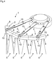
- the distance sensors 9 are for example according to Figure 4 arranged along the ring spaced apart from one another, each distance sensor forming a flat protective field.
- the protective fields together approximate, for example, the lateral surface of a cylinder or truncated cone or rotational hyperboloid
- the distance sensors 9 are evenly spaced. Due to the uniform spacing of the distance sensors 9 and an identical angular alignment of the detection beams, an almost uniform resolution within the protective field 5 is achieved.
- At least one spacer is arranged between the distance sensor modules.
- a distance between the distance sensor modules or a distance between the distance sensors can be set.
- the distance can be increased modularly.
- the spacers create a modular sensor system formed, which can be flexibly adapted to the desired dimensions and the desired number of distance sensors.
Description
Die vorliegende Erfindung betrifft ein Distanzsensormodul gemäß dem Oberbegriff von Anspruch 1 und ein Sensorsystem gemäß dem Oberbegriff von Anspruch 5.The present invention relates to a distance sensor module according to the preamble of claim 1 and a sensor system according to the preamble of
Zur Absicherung von Werkzeugen an Robotern bzw. der Prozesse der Werkzeuge mit den Werkstücken werden häufig berührungslos wirkende Schutzeinrichtungen verwendet.Contactless protective devices are often used to secure tools on robots or the processes between the tools and the workpieces.
Die Absicherung mit nur einer beispielsweisen immer gleichen Sensoranordnung stellt eine Herausforderung dar, weil die Geometrien der Werkzeuge und Werkstücke applikationsspezifisch sehr unterschiedlich sind.The protection with only one, for example, always the same sensor arrangement is a challenge because the geometries of the tools and workpieces are very different depending on the application.
Die
Die
Die
Die
Eine Aufgabe der Erfindung besteht darin, ein Distanzsensormodul bereitzustellen, welches mit anderen Distanzsensormodulen kombinierbar ist, um ein Schutzfeld um ein Werkzeug oder ein Werkstück an einem Roboterarm zu bilden.One object of the invention is to provide a distance sensor module which can be combined with other distance sensor modules in order to form a protective field around a tool or a workpiece on a robot arm.
Die Aufgabe wird gemäß Anspruch 1 gelöst durch ein Distanzsensormodul, wobei das Distanzsensormodul ein Gehäuse mit mindestens einem Distanzsensor aufweist, wobei das Gehäuse mindestens ein Drehgelenk mit einer Drehachse aufweist und zwei entgegengesetzte Verbindungsstellen aufweist, wobei jede Verbindungsstelle ein Verbindungselement aufweist zur Verbindung mit einem benachbarten Distanzsensormodul, wobei an dem Gehäuse ein längsverstellbarer Haltearm angeordnet ist und der längsverstellbare Haltearm an dem Drehgelenk befestigt ist.The object is achieved according to claim 1 by a distance sensor module, the distance sensor module having a housing with at least one distance sensor, the housing having at least one swivel joint with an axis of rotation and two opposite connection points, each connection point having a connection element for connection to an adjacent distance sensor module , wherein a longitudinally adjustable holding arm is arranged on the housing and the longitudinally adjustable holding arm is attached to the swivel joint.
Die Aufgabe wird weiter gemäß Anspruch 5 gelöst durch ein Sensorsystem mit optoelektronischen Distanzsensormodulen zur Überwachung eines Gefahrenbereichs an einem bewegbaren Maschinenteil mit mindestens einem Schutzfeld, wobei die optoelektronischen Distanzsensoren ringförmig in einem ersten Ring an dem bewegbaren Maschinenteil angeordnet sind, wobei an dem bewegbaren Maschinenteil ein Werkzeug angeordnet ist, wobei die Distanzsensormodule jeweils ein Gehäuse mit mindestens einem Distanzsensor aufweisen, wobei das Gehäuse mindestens ein Drehgelenk mit einer Drehachse aufweist und zwei entgegengesetzte Verbindungsstellen aufweist, wobei jede Verbindungsstelle ein Verbindungselement aufweist zur Verbindung mit einem benachbarten Distanzsensormodul, wobei an dem Gehäuse ein längsverstellbarer Haltearm angeordnet ist und der längsverstellbare Haltearm an dem Drehgelenk befestigt ist.The object is further achieved according to
Das Sensorsystem dient zum sicheren Überwachen des Gefahrenbereichs bzw. eines Überwachungsbereichs des bewegbaren Maschinenteils.The sensor system is used for safe monitoring of the danger area or a monitoring area of the movable machine part.
Sicherheit ist gemäß vorliegender Erfindung Sicherheit im Sinne von Maschinensicherheit. Beispielsweise regelt die Norm EN/IEC 61496 die Anforderungen an einen sicheren Sensor bzw. eine sichere berührungslos wirkende Schutzeinrichtung (BWS) zur Absicherung von Gefahrenbereichen. Maschinensicherheit ist in der Norm EN13849 geregelt. Die Sicherheit wird beispielsweise durch einen zweikanaligen oder zweikanalig diversitären Aufbau einer Auswerteeinheit zur Fehleraufdeckung und zur Funktionsprüfung gewährleistet. Der abstandsmessende Sensor bzw. Distanzsensor gemäß vorliegender Erfindung ist beispielsweise eigensicher ausgebildet und erkennt interne Fehler. Bei Entdeckung eines Fehlers wird beispielsweise ein Fehlersignal generiert. Weiter verfügt der Sensor bzw. Distanzsensor optional über eine Sensortestung.According to the present invention, safety is safety in the sense of machine safety. For example, the EN / IEC 61496 standard regulates the requirements for a safe sensor or a safe electro-sensitive protective device (ESPE) to protect danger areas. Machine safety is regulated in the EN13849 standard. Safety is guaranteed, for example, by a two-channel or two-channel diverse structure of an evaluation unit for fault detection and functional testing. The distance measuring sensor or distance sensor according to The present invention is, for example, designed to be intrinsically safe and detects internal errors. If an error is discovered, an error signal is generated, for example. The sensor or distance sensor also has an optional sensor test.
Eine Auswerteeinheit erkennt Schutzfeldverletzungen und kann ein sicherheitsgerichtetes Abschaltsignal ausgeben, um eine gefahrbringende Bewegung des Teils bzw. des Roboters zu stoppen bzw. das Teil oder den Roboter abzubremsen. Das kann z. B. über sichere Schaltsignale, z.B. OSSD-Signale (Output Safety Switching Device-Signale) oder sichere Distanzdaten, Abstandsdaten bzw. sichere Ortsdaten des Ein griffsereignisses realisiert werden. Beispielsweise ist die Auswerteeinheit zweikanalig ausgebildet.An evaluation unit detects protective field violations and can output a safety-related switch-off signal in order to stop a dangerous movement of the part or the robot or to brake the part or the robot. This can e.g. B. via safe switching signals, e.g. OSSD signals (Output Safety Switching Device signals) or safe distance data, distance data or safe location data of the input handle event can be realized. For example, the evaluation unit is designed with two channels.
Die Distanzsensormodule bilden einen Halter, in den die berührungslos wirkenden Distanzsensoren integrierbar sind. Aufgrund des Gehäuses des Distanzsensormoduls kann eine bewegliche Kette gebildet werden, mit der unterschiedlichste Anordnungen der Distanzsensormodule realisiert werden können. Damit lassen sich Mensch-Roboter-Kollaborations-Anwendungen mit unterschiedlichen Roboter-Werkzeuggeometrien oder Werkstückgeometrien absichern.The distance sensor modules form a holder in which the contactless distance sensors can be integrated. Due to the housing of the distance sensor module, a movable chain can be formed with which the most varied arrangements of the distance sensor modules can be implemented. This enables human-robot collaboration applications with different robot tool geometries or workpiece geometries to be secured.
Das Gehäuse besteht aus mindestens zwei Gehäuseteilen, die über das Drehgelenk miteinander verbunden sind.The housing consists of at least two housing parts that are connected to one another via the swivel joint.
Die mehreren Distanzsensoren sind mit einer Auswerteeinheit zur Auswertung der Distanzsensoren verbunden. Die Leitungsführung der einzelnen Distanzsensoren kann einfach über das Drehgelenk erfolgen. Dabei müssen die Leitungen nicht unterbrochen werden, da die mechanisch lösbare Schnittstelle zum Aufbau des Sensorsystems nicht das Drehgelenk ist, sondern die lösbare Verbindungsstelle.The multiple distance sensors are connected to an evaluation unit for evaluating the distance sensors. The cable routing of the individual distance sensors can easily be done via the swivel joint. The lines do not have to be interrupted, since the mechanically detachable interface for setting up the sensor system is not the swivel joint, but the detachable connection point.
Das Sensorsystem gemäß vorliegender Erfindung kann der Anwender selbst aufbauen, entsprechend den vorgegebenen geometrischen Gegebenheiten. Durch die Drehgelenke lässt sich die Geometrie genau an vorgegebene mechanische Adapter anpassen.The sensor system according to the present invention can be set up by the user himself, according to the given geometrical conditions. The swivel joints allow the geometry to be precisely adapted to given mechanical adapters.
Jedoch kann es auch vorgesehen sein, das Sensorsystem direkt beim Hersteller in der Produktion aufzubauen und manipulationssicher an den Anwender auszuliefern.However, provision can also be made to set up the sensor system directly at the manufacturer's production facility and to deliver it to the user in a tamper-proof manner.
Die Distanzsensoren sind beispielsweise entlang dem Ring beabstandet zueinander angeordnet, wobei jeder Sensor ein flächiges Schutzfeld bildet. Die Schutzfelder nähern zusammen beispielsweise die Mantelfläche eines Zylinders oder Kegelstumpfes oder Rotationshyperboloids an.The distance sensors are, for example, arranged at a distance from one another along the ring, each sensor forming a flat protective field. The protective fields together approximate, for example, the lateral surface of a cylinder or truncated cone or rotational hyperboloid.
Optional weisen die Distanzsensoren gleichmäßige Abstände auf. Durch die gleichmäßigen Abstände der Sensoren und eine jeweils identische Winkelausrichtung der Detektionsstrahlen wird eine nahezu gleichmäßige Auflösung innerhalb des Schutzfeldes erreicht.Optionally, the distance sensors are evenly spaced. Due to the even spacing of the sensors and an identical angular alignment of the detection beams, an almost uniform resolution within the protective field is achieved.
Die Distanzsensoren sind berührungslos wirkende abstandsmessende Distanzsensoren, wobei die Distanzsensoren einen Detektionsstrahl zum Erfassen von Objekten im Überwachungsbereich aufweisen.The distance sensors are non-contact distance measuring distance sensors, the distance sensors having a detection beam for detecting objects in the monitoring area.
Die Distanzsensoren können jeweils ein linienförmiges oder flächiges Schutzfeld aufweisen. Das flächige Schutzfeld ist fächerförmig ausgebildet mit einem bestimmten Öffnungswinkel von beispielsweise 2° bis 20°.The distance sensors can each have a linear or flat protective field. The flat protective field is fan-shaped with a certain opening angle of, for example, 2 ° to 20 °.
In Weiterbildung der Erfindung weist das Gehäuse mindestens zwei Distanzsensoren auf, wobei zwischen den Distanzsensoren das Drehgelenk angeordnet ist.In a further development of the invention, the housing has at least two distance sensors, the swivel joint being arranged between the distance sensors.
Die Distanzsensoren sind dabei optional so im Gehäuse angeordnet, dass bei einer Verbindung von Distanzsensormodulen bei gleichen Gelenkwinkeln äquidistante Abstände, also gleiche Abstände zwischen den optischen Achsen der Distanzsensoren, der Distanzsensoren eines Distanzsensormoduls und benachbarter Distanzsensormodule vorliegen. Durch die Anordnung von mindestens zwei Distanzsensoren pro Distanzsensormodul wird die Anzahl der Drehgelenke quasi halbiert.The distance sensors are optionally arranged in the housing in such a way that when distance sensor modules are connected, equidistant distances are present at the same joint angles, i.e. the same distances between the optical axes of the distance sensors, the distance sensors of a distance sensor module and adjacent distance sensor modules. By arranging at least two distance sensors per distance sensor module, the number of swivel joints is almost halved.
In Weiterbildung der Erfindung ist das Verbindungselement eine elektrische und mechanische Steckverbindung. Dadurch ist eine einfache elektrische Verbindung zwischen den Modulen bereitgestellt. Die Steckverbindung weist hierzu optional Rastmittel auf, um die Verbindung mechanisch zu sichern. Die Steckverbindung definiert dabei die mechanischen Abstände zwischen den Distanzsensoren.In a further development of the invention, the connecting element is an electrical and mechanical plug connection. This provides a simple electrical connection between the modules. For this purpose, the plug connection optionally has latching means in order to mechanically secure the connection. The plug connection defines the mechanical distances between the distance sensors.
In Weiterbildung der Erfindung ist zwischen den Distanzsensormodulen mindestens ein Distanzstück angeordnet. Dadurch kann ein Abstand der Distanzsensormodule zueinander eingestellt werden. Durch eine Verwendung mehrerer Distanzstücke kann der Abstand modular vergrößert werden. Durch die Distanzstücke wird ein modulares Sensorsystem gebildet, welches flexibel an die gewünschten Abmessungen und an die gewünschte Anzahl an Distanzsensoren angepasst werden kann.In a further development of the invention, at least one spacer is arranged between the distance sensor modules. This allows a distance between the distance sensor modules to be set. By using several spacers, the distance can be increased modularly. The spacers form a modular sensor system that can be flexibly adapted to the desired dimensions and to the desired number of distance sensors.
Gemäß der Erfindung ist an mindestens einem Gehäuse ein längsverstellbarer Haltearm angeordnet. Durch den Halterarm kann das Distanzsensormodul an dem Roboterarm bzw. einem Aufnahmekörper des Roboterarms befestigt werden. Der Haltearm ist dabei längenverstellbar ausgebildet. Bevorzugt ist jedes Distanzsensormodul mit jeweils einem Haltearm an dem Aufnahmekörper befestigt.According to the invention, a longitudinally adjustable holding arm is arranged on at least one housing. The distance sensor module can be fastened to the robot arm or a receiving body of the robot arm by the holder arm. The holding arm is designed to be adjustable in length. Each distance sensor module is preferably fastened to the receiving body with a respective holding arm.
Gemäß der Erfindung ist der längsverstellbare Haltearm an dem Drehgelenk befestigt. Dadurch ist die Drehachse des Drehgelenks identisch mit der Befestigungsachse des Haltearms.According to the invention, the longitudinally adjustable holding arm is attached to the swivel joint. As a result, the axis of rotation of the swivel joint is identical to the fastening axis of the holding arm.
Die Erfindung wird nachstehend auch hinsichtlich weiterer Vorteile und Merkmale unter Bezugnahme auf die beigefügte Zeichnung anhand von Ausführungsbeispielen erläutert. Die Figuren der Zeichnung zeigen in:
- Figur 1
- ein Distanzsensormodul mit einem Distanzsensor und einem Drehgelenk;
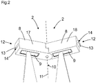
Figur 2- ein Distanzsensormodul mit zwei Distanzsensoren und einem Drehgelenk zwischen den Distanzsensoren;
Figur 3- ein Sensorsystem aus Distanzsensormodulen;
- Figur 4
- ein Sensorsystem aus Distanzsensormodulen und Haltearmen;
- Figure 1
- a distance sensor module with a distance sensor and a swivel joint;
- Figure 2
- a distance sensor module with two distance sensors and a swivel joint between the distance sensors;
- Figure 3
- a sensor system made up of distance sensor modules;
- Figure 4
- a sensor system made up of distance sensor modules and holding arms;
In den nachfolgenden Figuren sind identische Teile mit identischen Bezugszeichen versehen.In the following figures, identical parts are provided with identical reference symbols.
Das Gehäuse 8 besteht aus mindestens zwei Gehäuseteilen 17, 18 die über das Drehgelenk 10 miteinander verbunden sind.The
Die Distanzsensoren 9 sind berührungslos wirkende abstandsmessende Distanzsensoren 9, wobei die Distanzsensoren 9 einen Detektionsstrahl zum Erfassen von Objekten im Überwachungsbereich aufweisen.The
Gemäß
Gemäß
Die Distanzsensoren 9 sind dabei optional so im Gehäuse 8 angeordnet, dass bei einer Verbindung von Distanzsensormodulen 2 bei gleichen Gelenkwinkeln äquidistante Abstände, also gleiche Abstände zwischen den optischen Achsen der Distanzsensoren 9 eines Distanzsensormoduls 2 und benachbarter Distanzsensormodule 2 vorliegen. Durch die Anordnung von mindestens zwei Distanzsensoren 9 pro Distanzsensormodul 2 wird die Anzahl der Drehgelenke 10 quasi halbiert.The
Das Sensorsystem 1 dient zum sicheren Überwachen des Gefahrenbereichs 3 bzw. eines Überwachungsbereichs des bewegbaren Maschinenteils.The sensor system 1 is used to safely monitor the
Die Distanzsensoren 9 bilden gemäß
Die mehreren Distanzsensoren 9 sind mit einer Auswerteeinheit zur Auswertung der Distanzsensoren 9 verbunden. Die Leitungsführung der einzelnen Distanzsensoren 9 kann einfach über das Drehgelenk 10 erfolgen. Dabei müssen die Leitungen nicht unterbrochen werden, da die mechanisch lösbare Schnittstelle zum Aufbau des Sensorsystems 1 nicht das Drehgelenk 10 ist, sondern die lösbare Verbindungsstelle 12.The
Das Sensorsystem 1 gemäß
Die Distanzsensoren 9 können jeweils ein linienförmiges oder flächiges Schutzfeld 5 aufweisen. Das flächige Schutzfeld 5 ist fächerförmig ausgebildet mit einem bestimmten Öffnungswinkel von beispielsweise 2° bis 20°.The
Gemäß
Gemäß
Die Distanzsensoren 9 sind beispielsweise gemäß
Optional weisen die Distanzsensoren 9 gleichmäßige Abstände auf. Durch die gleichmäßigen Abstände der Distanzsensoren 9 und eine jeweils identische Winkelausrichtung der Detektionsstrahlen wird eine nahezu gleichmäßige Auflösung innerhalb des Schutzfeldes 5 erreicht.Optionally, the
Gemäß einer nicht dargestellten Ausführungsform ist zwischen den Distanzsensormodulen mindestens ein Distanzstück angeordnet. Dadurch kann ein Abstand der Distanzsensormodule zueinander bzw. ein Abstand der Distanzsensoren zueinander eingestellt werden. Durch eine Verwendung mehrerer Distanzstücke kann der Abstand modular vergrößert werden. Durch die Distanzstücke wird ein modulares Sensorsystem gebildet, welches flexibel an die gewünschten Abmessungen und an die gewünschte Anzahl an Distanzsensoren angepasst werden kann.According to an embodiment not shown, at least one spacer is arranged between the distance sensor modules. As a result, a distance between the distance sensor modules or a distance between the distance sensors can be set. By using several spacers, the distance can be increased modularly. The spacers create a modular sensor system formed, which can be flexibly adapted to the desired dimensions and the desired number of distance sensors.
Bezugszeichen:
- 1
- Sensorsystem
- 2
- Distanzsensormodule
- 3
- Gefahrenbereich
- 5
- Schutzfeld
- 8
- Gehäuse
- 9
- Distanzsensor
- 10
- Drehgelenk
- 11
- Drehachse
- 12
- Verbindungsstellen
- 13
- Verbindungselement
- 14
- Steckverbindung
- 15
- Haltearm
- 16
- Distanzstück
- 17
- Gehäuseteil
- 18
- Gehäuseteil
- 1
- Sensor system
- 2
- Distance sensor modules
- 3
- Danger zone
- 5
- Protective field
- 8th
- casing
- 9
- Distance sensor
- 10
- Swivel joint
- 11
- Axis of rotation
- 12
- Connection points
- 13
- Connecting element
- 14th
- Connector
- 15th
- Holding arm
- 16
- Spacer
- 17th
- Housing part
- 18th
- Housing part
Claims (5)
- Distance sensor module (2), the distance sensor module (2) having a housing (8) with at least one distance sensor (9), the housing (8) having at least one swivel joint (10) with an axis of rotation (11) and having two connecting points (12) arranged opposite one another on the housing (8), each connection point (12) having a connection element (13) for connection to an adjacent distance sensor module (2), characterized in that a longitudinally adjustable holding arm (15) is arranged on the housing (8) and the longitudinally adjustable holding arm (15) is attached to the swivel joint (10).
- Distance sensor module (2) according to claim 1, characterized in that the housing has at least two distance sensors, the swivel joint being arranged between the distance sensors.
- Distance sensor module (2) according to at least one of the preceding claims, characterized in that the connecting element (13) is an electrical and a mechanical plug-in connection (14).
- Distance sensor module (2) according to at least one of the preceding claims, characterized in that at least one spacer is arranged between the distance sensor modules.
- Sensor system (1) with optoelectronic distance sensor modules (2) for monitoring a danger area (3) on a movable machine part with at least one protective field (5), wherein the optoelectronic distance sensor modules (2) are arranged in a ring on the movable machine part (4), wherein a tool is arranged on the movable machine part, characterized in that the distance sensor modules are designed according to one of the claims 1 to 4.
Applications Claiming Priority (1)
| Application Number | Priority Date | Filing Date | Title |
|---|---|---|---|
| DE102018117372.5A DE102018117372B4 (en) | 2018-07-18 | 2018-07-18 | Sensor system and distance sensor module |
Publications (2)
| Publication Number | Publication Date |
|---|---|
| EP3597983A1 EP3597983A1 (en) | 2020-01-22 |
| EP3597983B1 true EP3597983B1 (en) | 2020-10-14 |
Family
ID=66857615
Family Applications (1)
| Application Number | Title | Priority Date | Filing Date |
|---|---|---|---|
| EP19177008.0A Active EP3597983B1 (en) | 2018-07-18 | 2019-05-28 | Sensor system and distance sensor module |
Country Status (2)
| Country | Link |
|---|---|
| EP (1) | EP3597983B1 (en) |
| DE (1) | DE102018117372B4 (en) |
Family Cites Families (7)
| Publication number | Priority date | Publication date | Assignee | Title |
|---|---|---|---|---|
| JPH0690900B2 (en) * | 1988-11-14 | 1994-11-14 | 株式会社キーエンス | Multi-axis photoelectric switch |
| EP1161694B1 (en) * | 1999-03-11 | 2008-12-10 | Omron Scientific Technologies, Inc. | Modular articulated light curtain |
| US6635862B2 (en) * | 2000-03-10 | 2003-10-21 | Scientific Technologies Incorporated | Mixed architecture light curtain system |
| DE102006003954A1 (en) * | 2006-01-26 | 2007-08-02 | Sick Ag | light Curtain |
| DE102009017466A1 (en) * | 2009-04-03 | 2010-10-07 | Balluff Gmbh | Photointerrupter |
| DE202014102335U1 (en) * | 2014-05-19 | 2015-08-24 | Sick Ag | sensor system |
| DE102015112656A1 (en) * | 2015-07-31 | 2017-02-02 | Sick Ag | Distance sensor |
-
2018
- 2018-07-18 DE DE102018117372.5A patent/DE102018117372B4/en not_active Expired - Fee Related
-
2019
- 2019-05-28 EP EP19177008.0A patent/EP3597983B1/en active Active
Non-Patent Citations (1)
| Title |
|---|
| None * |
Also Published As
| Publication number | Publication date |
|---|---|
| DE102018117372B4 (en) | 2020-04-02 |
| EP3597983A1 (en) | 2020-01-22 |
| DE102018117372A1 (en) | 2020-01-23 |
Similar Documents
| Publication | Publication Date | Title |
|---|---|---|
| EP3136127B1 (en) | Distance sensor and method with a distance sensor | |
| EP2231369B1 (en) | Robot and method for monitoring the torque on such a robot | |
| DE102019110882B4 (en) | Securing a moving machine part | |
| EP0106033A2 (en) | Feeler head for two or more coordinates measurement | |
| DE102014110548A1 (en) | Robotic arm system and method for calibrating parallelism | |
| DE102016213965A1 (en) | Plug-in adapter, adjustment instrument and associated robot | |
| DE102018216692B3 (en) | Robot hand guiding device | |
| DE69933947T2 (en) | METHOD FOR CELL ALIGNMENT AND IDENTIFICATION AND CALIBRATION OF A ROBOT TOOL | |
| DE102017103938A1 (en) | Device for measuring the roughness of a workpiece surface | |
| DE102016114835A1 (en) | robotic device | |
| EP3597983B1 (en) | Sensor system and distance sensor module | |
| EP3441200A1 (en) | Referencing method and device for industrial robots | |
| EP3578867B1 (en) | Sensor system with optoelectronic distance sensors | |
| DE102013221899A1 (en) | industrial robots | |
| DE202017104603U1 (en) | System for securing a machine | |
| DE202018104132U1 (en) | Sensor system and distance sensor module | |
| EP3578324B1 (en) | Sensor system with optoelectronic distance sensors | |
| DE102006041251B4 (en) | Device for detecting objects in a surveillance area | |
| EP2943313B1 (en) | Mechanical interface, module system and machine | |
| DE202020101253U1 (en) | system | |
| DE60024823T2 (en) | DEVICE FOR AUTOMATIC VERIFICATION OF CONNECTIONS TO ELECTRICAL HIGH VOLTAGE CABLES | |
| EP3875228B1 (en) | System for monitoring a hazard area at a movable machine part | |
| DE102012014249B4 (en) | Protective device for securing the movement of a robot arm that can be adjusted over several axes | |
| DE102018113362B4 (en) | Sensor system with optoelectronic distance sensor modules | |
| DE102020110340B4 (en) | robot |
Legal Events
| Date | Code | Title | Description |
|---|---|---|---|
| PUAI | Public reference made under article 153(3) epc to a published international application that has entered the european phase |
Free format text: ORIGINAL CODE: 0009012 |
|
| STAA | Information on the status of an ep patent application or granted ep patent |
Free format text: STATUS: THE APPLICATION HAS BEEN PUBLISHED |
|
| AK | Designated contracting states |
Kind code of ref document: A1 Designated state(s): AL AT BE BG CH CY CZ DE DK EE ES FI FR GB GR HR HU IE IS IT LI LT LU LV MC MK MT NL NO PL PT RO RS SE SI SK SM TR |
|
| AX | Request for extension of the european patent |
Extension state: BA ME |
|
| RAP1 | Party data changed (applicant data changed or rights of an application transferred) |
Owner name: SICK AG |
|
| STAA | Information on the status of an ep patent application or granted ep patent |
Free format text: STATUS: REQUEST FOR EXAMINATION WAS MADE |
|
| 17P | Request for examination filed |
Effective date: 20200312 |
|
| RBV | Designated contracting states (corrected) |
Designated state(s): AL AT BE BG CH CY CZ DE DK EE ES FI FR GB GR HR HU IE IS IT LI LT LU LV MC MK MT NL NO PL PT RO RS SE SI SK SM TR |
|
| GRAP | Despatch of communication of intention to grant a patent |
Free format text: ORIGINAL CODE: EPIDOSNIGR1 |
|
| STAA | Information on the status of an ep patent application or granted ep patent |
Free format text: STATUS: GRANT OF PATENT IS INTENDED |
|
| RIC1 | Information provided on ipc code assigned before grant |
Ipc: F16P 3/14 20060101AFI20200616BHEP Ipc: G01V 8/20 20060101ALI20200616BHEP |
|
| INTG | Intention to grant announced |
Effective date: 20200707 |
|
| GRAS | Grant fee paid |
Free format text: ORIGINAL CODE: EPIDOSNIGR3 |
|
| GRAA | (expected) grant |
Free format text: ORIGINAL CODE: 0009210 |
|
| STAA | Information on the status of an ep patent application or granted ep patent |
Free format text: STATUS: THE PATENT HAS BEEN GRANTED |
|
| AK | Designated contracting states |
Kind code of ref document: B1 Designated state(s): AL AT BE BG CH CY CZ DE DK EE ES FI FR GB GR HR HU IE IS IT LI LT LU LV MC MK MT NL NO PL PT RO RS SE SI SK SM TR |
|
| REG | Reference to a national code |
Ref country code: GB Ref legal event code: FG4D Free format text: NOT ENGLISH |
|
| REG | Reference to a national code |
Ref country code: AT Ref legal event code: REF Ref document number: 1323932 Country of ref document: AT Kind code of ref document: T Effective date: 20201015 Ref country code: CH Ref legal event code: EP |
|
| REG | Reference to a national code |
Ref country code: DE Ref legal event code: R096 Ref document number: 502019000294 Country of ref document: DE |
|
| REG | Reference to a national code |
Ref country code: IE Ref legal event code: FG4D Free format text: LANGUAGE OF EP DOCUMENT: GERMAN |
|
| REG | Reference to a national code |
Ref country code: NL Ref legal event code: MP Effective date: 20201014 |
|
| PG25 | Lapsed in a contracting state [announced via postgrant information from national office to epo] |
Ref country code: RS Free format text: LAPSE BECAUSE OF FAILURE TO SUBMIT A TRANSLATION OF THE DESCRIPTION OR TO PAY THE FEE WITHIN THE PRESCRIBED TIME-LIMIT Effective date: 20201014 Ref country code: PT Free format text: LAPSE BECAUSE OF FAILURE TO SUBMIT A TRANSLATION OF THE DESCRIPTION OR TO PAY THE FEE WITHIN THE PRESCRIBED TIME-LIMIT Effective date: 20210215 Ref country code: FI Free format text: LAPSE BECAUSE OF FAILURE TO SUBMIT A TRANSLATION OF THE DESCRIPTION OR TO PAY THE FEE WITHIN THE PRESCRIBED TIME-LIMIT Effective date: 20201014 Ref country code: NO Free format text: LAPSE BECAUSE OF FAILURE TO SUBMIT A TRANSLATION OF THE DESCRIPTION OR TO PAY THE FEE WITHIN THE PRESCRIBED TIME-LIMIT Effective date: 20210114 Ref country code: GR Free format text: LAPSE BECAUSE OF FAILURE TO SUBMIT A TRANSLATION OF THE DESCRIPTION OR TO PAY THE FEE WITHIN THE PRESCRIBED TIME-LIMIT Effective date: 20210115 |
|
| REG | Reference to a national code |
Ref country code: LT Ref legal event code: MG4D |
|
| PG25 | Lapsed in a contracting state [announced via postgrant information from national office to epo] |
Ref country code: BG Free format text: LAPSE BECAUSE OF FAILURE TO SUBMIT A TRANSLATION OF THE DESCRIPTION OR TO PAY THE FEE WITHIN THE PRESCRIBED TIME-LIMIT Effective date: 20210114 Ref country code: PL Free format text: LAPSE BECAUSE OF FAILURE TO SUBMIT A TRANSLATION OF THE DESCRIPTION OR TO PAY THE FEE WITHIN THE PRESCRIBED TIME-LIMIT Effective date: 20201014 Ref country code: LV Free format text: LAPSE BECAUSE OF FAILURE TO SUBMIT A TRANSLATION OF THE DESCRIPTION OR TO PAY THE FEE WITHIN THE PRESCRIBED TIME-LIMIT Effective date: 20201014 Ref country code: IS Free format text: LAPSE BECAUSE OF FAILURE TO SUBMIT A TRANSLATION OF THE DESCRIPTION OR TO PAY THE FEE WITHIN THE PRESCRIBED TIME-LIMIT Effective date: 20210214 Ref country code: SE Free format text: LAPSE BECAUSE OF FAILURE TO SUBMIT A TRANSLATION OF THE DESCRIPTION OR TO PAY THE FEE WITHIN THE PRESCRIBED TIME-LIMIT Effective date: 20201014 Ref country code: ES Free format text: LAPSE BECAUSE OF FAILURE TO SUBMIT A TRANSLATION OF THE DESCRIPTION OR TO PAY THE FEE WITHIN THE PRESCRIBED TIME-LIMIT Effective date: 20201014 |
|
| PG25 | Lapsed in a contracting state [announced via postgrant information from national office to epo] |
Ref country code: HR Free format text: LAPSE BECAUSE OF FAILURE TO SUBMIT A TRANSLATION OF THE DESCRIPTION OR TO PAY THE FEE WITHIN THE PRESCRIBED TIME-LIMIT Effective date: 20201014 Ref country code: NL Free format text: LAPSE BECAUSE OF FAILURE TO SUBMIT A TRANSLATION OF THE DESCRIPTION OR TO PAY THE FEE WITHIN THE PRESCRIBED TIME-LIMIT Effective date: 20201014 |
|
| REG | Reference to a national code |
Ref country code: DE Ref legal event code: R097 Ref document number: 502019000294 Country of ref document: DE |
|
| PG25 | Lapsed in a contracting state [announced via postgrant information from national office to epo] |
Ref country code: CZ Free format text: LAPSE BECAUSE OF FAILURE TO SUBMIT A TRANSLATION OF THE DESCRIPTION OR TO PAY THE FEE WITHIN THE PRESCRIBED TIME-LIMIT Effective date: 20201014 Ref country code: EE Free format text: LAPSE BECAUSE OF FAILURE TO SUBMIT A TRANSLATION OF THE DESCRIPTION OR TO PAY THE FEE WITHIN THE PRESCRIBED TIME-LIMIT Effective date: 20201014 Ref country code: SM Free format text: LAPSE BECAUSE OF FAILURE TO SUBMIT A TRANSLATION OF THE DESCRIPTION OR TO PAY THE FEE WITHIN THE PRESCRIBED TIME-LIMIT Effective date: 20201014 Ref country code: SK Free format text: LAPSE BECAUSE OF FAILURE TO SUBMIT A TRANSLATION OF THE DESCRIPTION OR TO PAY THE FEE WITHIN THE PRESCRIBED TIME-LIMIT Effective date: 20201014 Ref country code: RO Free format text: LAPSE BECAUSE OF FAILURE TO SUBMIT A TRANSLATION OF THE DESCRIPTION OR TO PAY THE FEE WITHIN THE PRESCRIBED TIME-LIMIT Effective date: 20201014 Ref country code: LT Free format text: LAPSE BECAUSE OF FAILURE TO SUBMIT A TRANSLATION OF THE DESCRIPTION OR TO PAY THE FEE WITHIN THE PRESCRIBED TIME-LIMIT Effective date: 20201014 |
|
| PLBE | No opposition filed within time limit |
Free format text: ORIGINAL CODE: 0009261 |
|
| STAA | Information on the status of an ep patent application or granted ep patent |
Free format text: STATUS: NO OPPOSITION FILED WITHIN TIME LIMIT |
|
| PG25 | Lapsed in a contracting state [announced via postgrant information from national office to epo] |
Ref country code: DK Free format text: LAPSE BECAUSE OF FAILURE TO SUBMIT A TRANSLATION OF THE DESCRIPTION OR TO PAY THE FEE WITHIN THE PRESCRIBED TIME-LIMIT Effective date: 20201014 |
|
| 26N | No opposition filed |
Effective date: 20210715 |
|
| PG25 | Lapsed in a contracting state [announced via postgrant information from national office to epo] |
Ref country code: IT Free format text: LAPSE BECAUSE OF FAILURE TO SUBMIT A TRANSLATION OF THE DESCRIPTION OR TO PAY THE FEE WITHIN THE PRESCRIBED TIME-LIMIT Effective date: 20201014 Ref country code: AL Free format text: LAPSE BECAUSE OF FAILURE TO SUBMIT A TRANSLATION OF THE DESCRIPTION OR TO PAY THE FEE WITHIN THE PRESCRIBED TIME-LIMIT Effective date: 20201014 |
|
| PG25 | Lapsed in a contracting state [announced via postgrant information from national office to epo] |
Ref country code: SI Free format text: LAPSE BECAUSE OF FAILURE TO SUBMIT A TRANSLATION OF THE DESCRIPTION OR TO PAY THE FEE WITHIN THE PRESCRIBED TIME-LIMIT Effective date: 20201014 |
|
| PG25 | Lapsed in a contracting state [announced via postgrant information from national office to epo] |
Ref country code: LU Free format text: LAPSE BECAUSE OF NON-PAYMENT OF DUE FEES Effective date: 20210528 Ref country code: MC Free format text: LAPSE BECAUSE OF FAILURE TO SUBMIT A TRANSLATION OF THE DESCRIPTION OR TO PAY THE FEE WITHIN THE PRESCRIBED TIME-LIMIT Effective date: 20201014 |
|
| REG | Reference to a national code |
Ref country code: BE Ref legal event code: MM Effective date: 20210531 |
|
| PG25 | Lapsed in a contracting state [announced via postgrant information from national office to epo] |
Ref country code: IE Free format text: LAPSE BECAUSE OF NON-PAYMENT OF DUE FEES Effective date: 20210528 |
|
| PG25 | Lapsed in a contracting state [announced via postgrant information from national office to epo] |
Ref country code: IS Free format text: LAPSE BECAUSE OF FAILURE TO SUBMIT A TRANSLATION OF THE DESCRIPTION OR TO PAY THE FEE WITHIN THE PRESCRIBED TIME-LIMIT Effective date: 20210214 Ref country code: FR Free format text: LAPSE BECAUSE OF NON-PAYMENT OF DUE FEES Effective date: 20210531 |
|
| PG25 | Lapsed in a contracting state [announced via postgrant information from national office to epo] |
Ref country code: BE Free format text: LAPSE BECAUSE OF NON-PAYMENT OF DUE FEES Effective date: 20210531 |
|
| REG | Reference to a national code |
Ref country code: CH Ref legal event code: PL |
|
| PG25 | Lapsed in a contracting state [announced via postgrant information from national office to epo] |
Ref country code: LI Free format text: LAPSE BECAUSE OF NON-PAYMENT OF DUE FEES Effective date: 20220531 Ref country code: CH Free format text: LAPSE BECAUSE OF NON-PAYMENT OF DUE FEES Effective date: 20220531 |
|
| PG25 | Lapsed in a contracting state [announced via postgrant information from national office to epo] |
Ref country code: CY Free format text: LAPSE BECAUSE OF FAILURE TO SUBMIT A TRANSLATION OF THE DESCRIPTION OR TO PAY THE FEE WITHIN THE PRESCRIBED TIME-LIMIT Effective date: 20201014 |
|
| PG25 | Lapsed in a contracting state [announced via postgrant information from national office to epo] |
Ref country code: HU Free format text: LAPSE BECAUSE OF FAILURE TO SUBMIT A TRANSLATION OF THE DESCRIPTION OR TO PAY THE FEE WITHIN THE PRESCRIBED TIME-LIMIT; INVALID AB INITIO Effective date: 20190528 |
|
| PGFP | Annual fee paid to national office [announced via postgrant information from national office to epo] |
Ref country code: DE Payment date: 20230519 Year of fee payment: 5 |
|
| GBPC | Gb: european patent ceased through non-payment of renewal fee |
Effective date: 20230528 |