EP3597885A1 - Gear train architecture for a multi-spool gas turbine engine - Google Patents
Gear train architecture for a multi-spool gas turbine engine Download PDFInfo
- Publication number
- EP3597885A1 EP3597885A1 EP19193921.4A EP19193921A EP3597885A1 EP 3597885 A1 EP3597885 A1 EP 3597885A1 EP 19193921 A EP19193921 A EP 19193921A EP 3597885 A1 EP3597885 A1 EP 3597885A1
- Authority
- EP
- European Patent Office
- Prior art keywords
- compressor
- spool
- turbine
- engine
- shaft
- Prior art date
- Legal status (The legal status is an assumption and is not a legal conclusion. Google has not performed a legal analysis and makes no representation as to the accuracy of the status listed.)
- Granted
Links
- 238000004891 communication Methods 0.000 claims description 7
- 239000012530 fluid Substances 0.000 claims description 6
- 230000009467 reduction Effects 0.000 claims description 6
- 230000008878 coupling Effects 0.000 claims description 5
- 238000010168 coupling process Methods 0.000 claims description 5
- 238000005859 coupling reaction Methods 0.000 claims description 5
- 239000007789 gas Substances 0.000 description 22
- 239000000567 combustion gas Substances 0.000 description 6
- 238000012546 transfer Methods 0.000 description 6
- 230000006835 compression Effects 0.000 description 4
- 238000007906 compression Methods 0.000 description 4
- 239000000446 fuel Substances 0.000 description 3
- 238000009434 installation Methods 0.000 description 3
- 238000000034 method Methods 0.000 description 2
- 238000012986 modification Methods 0.000 description 2
- 230000004048 modification Effects 0.000 description 2
- 230000002457 bidirectional effect Effects 0.000 description 1
- 238000013461 design Methods 0.000 description 1
- 230000014509 gene expression Effects 0.000 description 1
- 230000006872 improvement Effects 0.000 description 1
- 230000008569 process Effects 0.000 description 1
- 238000012552 review Methods 0.000 description 1
- 238000011144 upstream manufacturing Methods 0.000 description 1
Images
Classifications
-
- F—MECHANICAL ENGINEERING; LIGHTING; HEATING; WEAPONS; BLASTING
- F02—COMBUSTION ENGINES; HOT-GAS OR COMBUSTION-PRODUCT ENGINE PLANTS
- F02C—GAS-TURBINE PLANTS; AIR INTAKES FOR JET-PROPULSION PLANTS; CONTROLLING FUEL SUPPLY IN AIR-BREATHING JET-PROPULSION PLANTS
- F02C7/00—Features, components parts, details or accessories, not provided for in, or of interest apart form groups F02C1/00 - F02C6/00; Air intakes for jet-propulsion plants
- F02C7/36—Power transmission arrangements between the different shafts of the gas turbine plant, or between the gas-turbine plant and the power user
-
- F—MECHANICAL ENGINEERING; LIGHTING; HEATING; WEAPONS; BLASTING
- F02—COMBUSTION ENGINES; HOT-GAS OR COMBUSTION-PRODUCT ENGINE PLANTS
- F02C—GAS-TURBINE PLANTS; AIR INTAKES FOR JET-PROPULSION PLANTS; CONTROLLING FUEL SUPPLY IN AIR-BREATHING JET-PROPULSION PLANTS
- F02C3/00—Gas-turbine plants characterised by the use of combustion products as the working fluid
- F02C3/14—Gas-turbine plants characterised by the use of combustion products as the working fluid characterised by the arrangement of the combustion chamber in the plant
- F02C3/145—Gas-turbine plants characterised by the use of combustion products as the working fluid characterised by the arrangement of the combustion chamber in the plant the combustion chamber being in the reverse flow-type
-
- B—PERFORMING OPERATIONS; TRANSPORTING
- B64—AIRCRAFT; AVIATION; COSMONAUTICS
- B64D—EQUIPMENT FOR FITTING IN OR TO AIRCRAFT; FLIGHT SUITS; PARACHUTES; ARRANGEMENTS OR MOUNTING OF POWER PLANTS OR PROPULSION TRANSMISSIONS IN AIRCRAFT
- B64D27/00—Arrangement or mounting of power plant in aircraft; Aircraft characterised thereby
- B64D27/02—Aircraft characterised by the type or position of power plant
- B64D27/10—Aircraft characterised by the type or position of power plant of gas-turbine type
-
- B—PERFORMING OPERATIONS; TRANSPORTING
- B64—AIRCRAFT; AVIATION; COSMONAUTICS
- B64D—EQUIPMENT FOR FITTING IN OR TO AIRCRAFT; FLIGHT SUITS; PARACHUTES; ARRANGEMENTS OR MOUNTING OF POWER PLANTS OR PROPULSION TRANSMISSIONS IN AIRCRAFT
- B64D35/00—Transmitting power from power plant to propellers or rotors; Arrangements of transmissions
- B64D35/04—Transmitting power from power plant to propellers or rotors; Arrangements of transmissions characterised by the transmission driving a plurality of propellers or rotors
-
- F—MECHANICAL ENGINEERING; LIGHTING; HEATING; WEAPONS; BLASTING
- F01—MACHINES OR ENGINES IN GENERAL; ENGINE PLANTS IN GENERAL; STEAM ENGINES
- F01D—NON-POSITIVE DISPLACEMENT MACHINES OR ENGINES, e.g. STEAM TURBINES
- F01D15/00—Adaptations of machines or engines for special use; Combinations of engines with devices driven thereby
- F01D15/12—Combinations with mechanical gearing
-
- F—MECHANICAL ENGINEERING; LIGHTING; HEATING; WEAPONS; BLASTING
- F01—MACHINES OR ENGINES IN GENERAL; ENGINE PLANTS IN GENERAL; STEAM ENGINES
- F01D—NON-POSITIVE DISPLACEMENT MACHINES OR ENGINES, e.g. STEAM TURBINES
- F01D25/00—Component parts, details, or accessories, not provided for in, or of interest apart from, other groups
- F01D25/18—Lubricating arrangements
-
- F—MECHANICAL ENGINEERING; LIGHTING; HEATING; WEAPONS; BLASTING
- F01—MACHINES OR ENGINES IN GENERAL; ENGINE PLANTS IN GENERAL; STEAM ENGINES
- F01D—NON-POSITIVE DISPLACEMENT MACHINES OR ENGINES, e.g. STEAM TURBINES
- F01D5/00—Blades; Blade-carrying members; Heating, heat-insulating, cooling or antivibration means on the blades or the members
- F01D5/02—Blade-carrying members, e.g. rotors
- F01D5/026—Shaft to shaft connections
-
- F—MECHANICAL ENGINEERING; LIGHTING; HEATING; WEAPONS; BLASTING
- F02—COMBUSTION ENGINES; HOT-GAS OR COMBUSTION-PRODUCT ENGINE PLANTS
- F02C—GAS-TURBINE PLANTS; AIR INTAKES FOR JET-PROPULSION PLANTS; CONTROLLING FUEL SUPPLY IN AIR-BREATHING JET-PROPULSION PLANTS
- F02C3/00—Gas-turbine plants characterised by the use of combustion products as the working fluid
- F02C3/04—Gas-turbine plants characterised by the use of combustion products as the working fluid having a turbine driving a compressor
- F02C3/08—Gas-turbine plants characterised by the use of combustion products as the working fluid having a turbine driving a compressor the compressor comprising at least one radial stage
-
- F—MECHANICAL ENGINEERING; LIGHTING; HEATING; WEAPONS; BLASTING
- F02—COMBUSTION ENGINES; HOT-GAS OR COMBUSTION-PRODUCT ENGINE PLANTS
- F02C—GAS-TURBINE PLANTS; AIR INTAKES FOR JET-PROPULSION PLANTS; CONTROLLING FUEL SUPPLY IN AIR-BREATHING JET-PROPULSION PLANTS
- F02C3/00—Gas-turbine plants characterised by the use of combustion products as the working fluid
- F02C3/04—Gas-turbine plants characterised by the use of combustion products as the working fluid having a turbine driving a compressor
- F02C3/10—Gas-turbine plants characterised by the use of combustion products as the working fluid having a turbine driving a compressor with another turbine driving an output shaft but not driving the compressor
-
- F—MECHANICAL ENGINEERING; LIGHTING; HEATING; WEAPONS; BLASTING
- F02—COMBUSTION ENGINES; HOT-GAS OR COMBUSTION-PRODUCT ENGINE PLANTS
- F02C—GAS-TURBINE PLANTS; AIR INTAKES FOR JET-PROPULSION PLANTS; CONTROLLING FUEL SUPPLY IN AIR-BREATHING JET-PROPULSION PLANTS
- F02C3/00—Gas-turbine plants characterised by the use of combustion products as the working fluid
- F02C3/04—Gas-turbine plants characterised by the use of combustion products as the working fluid having a turbine driving a compressor
- F02C3/107—Gas-turbine plants characterised by the use of combustion products as the working fluid having a turbine driving a compressor with two or more rotors connected by power transmission
- F02C3/113—Gas-turbine plants characterised by the use of combustion products as the working fluid having a turbine driving a compressor with two or more rotors connected by power transmission with variable power transmission between rotors
-
- F—MECHANICAL ENGINEERING; LIGHTING; HEATING; WEAPONS; BLASTING
- F02—COMBUSTION ENGINES; HOT-GAS OR COMBUSTION-PRODUCT ENGINE PLANTS
- F02C—GAS-TURBINE PLANTS; AIR INTAKES FOR JET-PROPULSION PLANTS; CONTROLLING FUEL SUPPLY IN AIR-BREATHING JET-PROPULSION PLANTS
- F02C6/00—Plural gas-turbine plants; Combinations of gas-turbine plants with other apparatus; Adaptations of gas- turbine plants for special use
- F02C6/20—Adaptations of gas-turbine plants for driving vehicles
- F02C6/206—Adaptations of gas-turbine plants for driving vehicles the vehicles being airscrew driven
-
- F—MECHANICAL ENGINEERING; LIGHTING; HEATING; WEAPONS; BLASTING
- F02—COMBUSTION ENGINES; HOT-GAS OR COMBUSTION-PRODUCT ENGINE PLANTS
- F02C—GAS-TURBINE PLANTS; AIR INTAKES FOR JET-PROPULSION PLANTS; CONTROLLING FUEL SUPPLY IN AIR-BREATHING JET-PROPULSION PLANTS
- F02C7/00—Features, components parts, details or accessories, not provided for in, or of interest apart form groups F02C1/00 - F02C6/00; Air intakes for jet-propulsion plants
- F02C7/06—Arrangements of bearings; Lubricating
-
- F—MECHANICAL ENGINEERING; LIGHTING; HEATING; WEAPONS; BLASTING
- F02—COMBUSTION ENGINES; HOT-GAS OR COMBUSTION-PRODUCT ENGINE PLANTS
- F02C—GAS-TURBINE PLANTS; AIR INTAKES FOR JET-PROPULSION PLANTS; CONTROLLING FUEL SUPPLY IN AIR-BREATHING JET-PROPULSION PLANTS
- F02C7/00—Features, components parts, details or accessories, not provided for in, or of interest apart form groups F02C1/00 - F02C6/00; Air intakes for jet-propulsion plants
- F02C7/32—Arrangement, mounting, or driving, of auxiliaries
-
- F—MECHANICAL ENGINEERING; LIGHTING; HEATING; WEAPONS; BLASTING
- F02—COMBUSTION ENGINES; HOT-GAS OR COMBUSTION-PRODUCT ENGINE PLANTS
- F02K—JET-PROPULSION PLANTS
- F02K3/00—Plants including a gas turbine driving a compressor or a ducted fan
- F02K3/02—Plants including a gas turbine driving a compressor or a ducted fan in which part of the working fluid by-passes the turbine and combustion chamber
- F02K3/04—Plants including a gas turbine driving a compressor or a ducted fan in which part of the working fluid by-passes the turbine and combustion chamber the plant including ducted fans, i.e. fans with high volume, low pressure outputs, for augmenting the jet thrust, e.g. of double-flow type
- F02K3/06—Plants including a gas turbine driving a compressor or a ducted fan in which part of the working fluid by-passes the turbine and combustion chamber the plant including ducted fans, i.e. fans with high volume, low pressure outputs, for augmenting the jet thrust, e.g. of double-flow type with front fan
-
- F—MECHANICAL ENGINEERING; LIGHTING; HEATING; WEAPONS; BLASTING
- F16—ENGINEERING ELEMENTS AND UNITS; GENERAL MEASURES FOR PRODUCING AND MAINTAINING EFFECTIVE FUNCTIONING OF MACHINES OR INSTALLATIONS; THERMAL INSULATION IN GENERAL
- F16H—GEARING
- F16H57/00—General details of gearing
- F16H57/04—Features relating to lubrication or cooling or heating
- F16H57/048—Type of gearings to be lubricated, cooled or heated
- F16H57/0493—Gearings with spur or bevel gears
- F16H57/0495—Gearings with spur or bevel gears with fixed gear ratio
-
- F—MECHANICAL ENGINEERING; LIGHTING; HEATING; WEAPONS; BLASTING
- F05—INDEXING SCHEMES RELATING TO ENGINES OR PUMPS IN VARIOUS SUBCLASSES OF CLASSES F01-F04
- F05D—INDEXING SCHEME FOR ASPECTS RELATING TO NON-POSITIVE-DISPLACEMENT MACHINES OR ENGINES, GAS-TURBINES OR JET-PROPULSION PLANTS
- F05D2220/00—Application
- F05D2220/30—Application in turbines
- F05D2220/32—Application in turbines in gas turbines
- F05D2220/323—Application in turbines in gas turbines for aircraft propulsion, e.g. jet engines
-
- F—MECHANICAL ENGINEERING; LIGHTING; HEATING; WEAPONS; BLASTING
- F05—INDEXING SCHEMES RELATING TO ENGINES OR PUMPS IN VARIOUS SUBCLASSES OF CLASSES F01-F04
- F05D—INDEXING SCHEME FOR ASPECTS RELATING TO NON-POSITIVE-DISPLACEMENT MACHINES OR ENGINES, GAS-TURBINES OR JET-PROPULSION PLANTS
- F05D2220/00—Application
- F05D2220/30—Application in turbines
- F05D2220/32—Application in turbines in gas turbines
- F05D2220/324—Application in turbines in gas turbines to drive unshrouded, low solidity propeller
-
- F—MECHANICAL ENGINEERING; LIGHTING; HEATING; WEAPONS; BLASTING
- F05—INDEXING SCHEMES RELATING TO ENGINES OR PUMPS IN VARIOUS SUBCLASSES OF CLASSES F01-F04
- F05D—INDEXING SCHEME FOR ASPECTS RELATING TO NON-POSITIVE-DISPLACEMENT MACHINES OR ENGINES, GAS-TURBINES OR JET-PROPULSION PLANTS
- F05D2220/00—Application
- F05D2220/30—Application in turbines
- F05D2220/32—Application in turbines in gas turbines
- F05D2220/329—Application in turbines in gas turbines in helicopters
-
- F—MECHANICAL ENGINEERING; LIGHTING; HEATING; WEAPONS; BLASTING
- F05—INDEXING SCHEMES RELATING TO ENGINES OR PUMPS IN VARIOUS SUBCLASSES OF CLASSES F01-F04
- F05D—INDEXING SCHEME FOR ASPECTS RELATING TO NON-POSITIVE-DISPLACEMENT MACHINES OR ENGINES, GAS-TURBINES OR JET-PROPULSION PLANTS
- F05D2230/00—Manufacture
- F05D2230/70—Disassembly methods
-
- F—MECHANICAL ENGINEERING; LIGHTING; HEATING; WEAPONS; BLASTING
- F05—INDEXING SCHEMES RELATING TO ENGINES OR PUMPS IN VARIOUS SUBCLASSES OF CLASSES F01-F04
- F05D—INDEXING SCHEME FOR ASPECTS RELATING TO NON-POSITIVE-DISPLACEMENT MACHINES OR ENGINES, GAS-TURBINES OR JET-PROPULSION PLANTS
- F05D2230/00—Manufacture
- F05D2230/72—Maintenance
-
- F—MECHANICAL ENGINEERING; LIGHTING; HEATING; WEAPONS; BLASTING
- F05—INDEXING SCHEMES RELATING TO ENGINES OR PUMPS IN VARIOUS SUBCLASSES OF CLASSES F01-F04
- F05D—INDEXING SCHEME FOR ASPECTS RELATING TO NON-POSITIVE-DISPLACEMENT MACHINES OR ENGINES, GAS-TURBINES OR JET-PROPULSION PLANTS
- F05D2240/00—Components
- F05D2240/60—Shafts
- F05D2240/61—Hollow
-
- F—MECHANICAL ENGINEERING; LIGHTING; HEATING; WEAPONS; BLASTING
- F05—INDEXING SCHEMES RELATING TO ENGINES OR PUMPS IN VARIOUS SUBCLASSES OF CLASSES F01-F04
- F05D—INDEXING SCHEME FOR ASPECTS RELATING TO NON-POSITIVE-DISPLACEMENT MACHINES OR ENGINES, GAS-TURBINES OR JET-PROPULSION PLANTS
- F05D2250/00—Geometry
- F05D2250/30—Arrangement of components
- F05D2250/36—Arrangement of components in inner-outer relationship, e.g. shaft-bearing arrangements
-
- F—MECHANICAL ENGINEERING; LIGHTING; HEATING; WEAPONS; BLASTING
- F05—INDEXING SCHEMES RELATING TO ENGINES OR PUMPS IN VARIOUS SUBCLASSES OF CLASSES F01-F04
- F05D—INDEXING SCHEME FOR ASPECTS RELATING TO NON-POSITIVE-DISPLACEMENT MACHINES OR ENGINES, GAS-TURBINES OR JET-PROPULSION PLANTS
- F05D2260/00—Function
- F05D2260/30—Retaining components in desired mutual position
- F05D2260/31—Retaining bolts or nuts
-
- F—MECHANICAL ENGINEERING; LIGHTING; HEATING; WEAPONS; BLASTING
- F05—INDEXING SCHEMES RELATING TO ENGINES OR PUMPS IN VARIOUS SUBCLASSES OF CLASSES F01-F04
- F05D—INDEXING SCHEME FOR ASPECTS RELATING TO NON-POSITIVE-DISPLACEMENT MACHINES OR ENGINES, GAS-TURBINES OR JET-PROPULSION PLANTS
- F05D2260/00—Function
- F05D2260/30—Retaining components in desired mutual position
- F05D2260/36—Retaining components in desired mutual position by a form fit connection, e.g. by interlocking
-
- F—MECHANICAL ENGINEERING; LIGHTING; HEATING; WEAPONS; BLASTING
- F05—INDEXING SCHEMES RELATING TO ENGINES OR PUMPS IN VARIOUS SUBCLASSES OF CLASSES F01-F04
- F05D—INDEXING SCHEME FOR ASPECTS RELATING TO NON-POSITIVE-DISPLACEMENT MACHINES OR ENGINES, GAS-TURBINES OR JET-PROPULSION PLANTS
- F05D2260/00—Function
- F05D2260/40—Transmission of power
- F05D2260/403—Transmission of power through the shape of the drive components
- F05D2260/4031—Transmission of power through the shape of the drive components as in toothed gearing
- F05D2260/40311—Transmission of power through the shape of the drive components as in toothed gearing of the epicyclical, planetary or differential type
-
- F—MECHANICAL ENGINEERING; LIGHTING; HEATING; WEAPONS; BLASTING
- F05—INDEXING SCHEMES RELATING TO ENGINES OR PUMPS IN VARIOUS SUBCLASSES OF CLASSES F01-F04
- F05D—INDEXING SCHEME FOR ASPECTS RELATING TO NON-POSITIVE-DISPLACEMENT MACHINES OR ENGINES, GAS-TURBINES OR JET-PROPULSION PLANTS
- F05D2260/00—Function
- F05D2260/98—Lubrication
-
- Y—GENERAL TAGGING OF NEW TECHNOLOGICAL DEVELOPMENTS; GENERAL TAGGING OF CROSS-SECTIONAL TECHNOLOGIES SPANNING OVER SEVERAL SECTIONS OF THE IPC; TECHNICAL SUBJECTS COVERED BY FORMER USPC CROSS-REFERENCE ART COLLECTIONS [XRACs] AND DIGESTS
- Y02—TECHNOLOGIES OR APPLICATIONS FOR MITIGATION OR ADAPTATION AGAINST CLIMATE CHANGE
- Y02T—CLIMATE CHANGE MITIGATION TECHNOLOGIES RELATED TO TRANSPORTATION
- Y02T50/00—Aeronautics or air transport
- Y02T50/40—Weight reduction
-
- Y—GENERAL TAGGING OF NEW TECHNOLOGICAL DEVELOPMENTS; GENERAL TAGGING OF CROSS-SECTIONAL TECHNOLOGIES SPANNING OVER SEVERAL SECTIONS OF THE IPC; TECHNICAL SUBJECTS COVERED BY FORMER USPC CROSS-REFERENCE ART COLLECTIONS [XRACs] AND DIGESTS
- Y02—TECHNOLOGIES OR APPLICATIONS FOR MITIGATION OR ADAPTATION AGAINST CLIMATE CHANGE
- Y02T—CLIMATE CHANGE MITIGATION TECHNOLOGIES RELATED TO TRANSPORTATION
- Y02T50/00—Aeronautics or air transport
- Y02T50/60—Efficient propulsion technologies, e.g. for aircraft
Definitions
- the application relates to gas turbine engines and, more particularly, to a gear train architecture for a multi-spool engine.
- Multi-spool gas turbine engines typically have a tower shaft for providing a drive input to an accessory gear box (AGB) asymmetrically mounted on a side of the engine.
- AGB accessory gear box
- Such engine architecture may contribute to an increase in diameter of the engine envelope.
- the extension of the tower shaft through the gaspath may impact the engine's aerodynamic performance.
- a multi-spool gas turbine engine comprising: a low pressure (LP) spool; a high pressure (HP) spool fluidly connected to the LP spool by a gaspath, the LP spool comprising an LP compressor and an LP turbine, the HP spool comprising an HP turbine and an HP compressor; an accessory gear box (AGB), the LP compressor positioned between the HP compressor and the AGB; and first and second gear trains positioned between the HP compressor and the LP compressor and radially inwardly from the gaspath, the first gear train coupling the LP turbine to the LP compressor, the second gear train coupling the HP spool to the AGB.
- LP low pressure
- HP high pressure
- the AGB may have an input shaft, the input shaft extending through a central bore of the LP compressor into meshing engagement with a gear of the second gear train.
- a gear ratio of the first gear train may be selected to permit the LP compressor to rotate at a different speed than the LP turbine.
- the engine may be an aircraft engine having a reverse flow configuration including an air inlet disposed aft of the LP compressor along an intended direction of travel of the aircraft engine.
- the AGB (50) may be disposed aft of the air inlet,
- the aircraft engine may be a turboprop engine including a reduction gear drivingly connected to the LP turbine, the reduction gear box disposed forward of the LP turbine.
- the gaspath may have an inner gaspath wall.
- the first and second gear trains may be contained in a central chamber circumscribed by the inner gaspath wall.
- the central chamber may contain oil.
- the central chamber may be fluidly connected to an oil chamber of the AGB, thereby providing for a combined oil sump for the AGB and the first and second gear trains.
- the LP spool may comprise an LP shaft.
- the LP shaft may have an end disposed between the HP compressor and the LP compressor, said end of the LP shaft providing a drive input to the first gear train.
- the gaspath may have an inner gaspath wall, the inner gaspath wall providing support to the first and second gear trains.
- a multi-spool gas turbine engine comprising: a low pressure (LP) spool; a high pressure (HP) spool fluidly connected to the LP spool via a gaspath, the LP spool and the HP spool being mounted for rotation about a central axis; the LP pressure spool comprising an LP compressor and an LP turbine , the HP spool comprising an HP turbine and an HP compressor; an accessory gear box (AGB) drivingly connected to the HP spool, the LP compressor being axially positioned between the HP compressor and the AGB and drivingly connected to the LP turbine via a gear train positioned axially between the HP compressor and the LP compressor and radially inwardly from the gaspath.
- LP low pressure
- HP high pressure
- the LP turbine may be drivingly mounted to an LP shaft extending axially along the central axis within an HP shaft connecting the HP turbine to the HP compressor.
- the LP shaft may have one end thereof projecting axially out of the HP shaft, said gear train being provided at said one end of the LP shaft.
- gear train may be contained within a central chamber circumscribed by an inner gaspath wall between the HP compressor and the LP compressor.
- the gear train may comprise a first gear mounted to said one end of the LP shaft.
- the first gear may be in meshing engagement with a second gear provided at a first end of a transfer shaft, a third gear provided at a second end of the transfer shaft, and a fourth gear provided on said LP compressor.
- the fourth gear may be in meshing engagement with the third gear.
- the engine may be an aircraft engine.
- the AGB may be aft of the LP compressor along an intended direction of travel of the aircraft engine.
- the LP compressor may be aft of the HP compressor.
- the HP compressor may be aft of the HP turbine.
- the HP turbine may be aft of the LP turbine.
- the LP turbine may be drivingly connected to an output drive shaft having a front end configured to drivingly engage a rotatable load.
- the LP turbine may be aft of the front end of the output drive shaft.
- a further gear train may be provided between the HP compressor and the LP compressor.
- the further gear train may interconnect the HP spool to an input drive shaft of the AGB.
- the input drive shaft may extend axially through a central bore of the LP compressor.
- a reverse flow gas turbine engine comprising: an output drive shaft having a front end configurable to drivingly engage a rotatable load; a low pressure (LP) spool including an LP turbine drivingly engaged to the output drive shaft, and an LP compressor drivingly connected to the LP turbine via a gear train, the LP turbine disposed forward of the LP compressor relative to a front end of the output drive shaft; and a high pressure HP spool including an HP turbine and an HP compressor drivingly engaged to an HP shaft rotatable independently of the LP spool, the HP compressor disposed forward of the LP compressor and in fluid communication therewith via a gaspath, and the HP turbine disposed aft of the LP turbine and in fluid communication therewith through said gaspath; wherein the gear train interconnecting the LP compressor and the LP turbine is disposed between the LP compressor
- the reverse flow gas turbine engine may further comprise an accessory gearbox (AGB).
- AGB may be mounted aft of the LP compressor.
- the AGB may have an input shaft extending through a central bore of the LP compressor.
- the input shaft may be drivingly connected to the HP spool via a further gear train.
- the gear train and the further gear train may be housed in a same chamber circumscribed by an inner gaspath wall of the gaspath.
- the chamber in which are disposed the gear train and the further gear train may be in fluid flow communication with an oil chamber of the AGB axially through the center of the LP compressor.
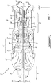
- Fig. 1 illustrates a gas turbine engine 10 of a type preferably provided for use in subsonic flight, generally comprising in serial flow communication an air inlet 11, a compressor section 12 for pressurizing the air from the air inlet 11, a combustor 13 in which the compressed air is mixed with fuel and ignited for generating an annular stream of hot combustion gases, a turbine section 14 for extracting energy from the combustion gases, an exhaust outlet 15 through which the combustion gases exit the engine 10.
- the engine 10 further has a drive output shaft 16 having a front end configured to drive a rotatable load (not shown).
- the rotatable load can, for instance, take the form of a propeller or a rotor, such as a helicopter main rotor.
- the engine 10 can be configured as a turboprop engine or a turboshaft engine.
- Fig. 1 illustrates a turboprop configuration.
- the gas turbine engine 10 has a centerline or longitudinal center axis 17 about which the compressor and turbine rotors rotate.
- the gas turbine engine 10 has an axially extending central core which defines a gaspath 18 through which gases flow, as depicted by flow arrows in Fig. 1 .
- the exemplary embodiment shown in Fig. 1 is a "reverse-flow” engine because gases flow through the gaspath 18 from the air inlet 11 at a rear portion thereof, to the exhaust outlet 15 at a front portion thereof. This is in contrast to "through-flow" gas turbine engines in which gases flow through the core of the engine from a front portion to a rear portion.
- the direction of the flow of gases through the gaspath 18 of the engine 10 disclosed herein can be better appreciated by considering that the gases flow through the gaspath 18 in the same direction D as the one along which an aircraft engine travels during flight. Stated differently, gases flow through the engine 10 from a rear end thereof towards the output shaft 16.
- forward and “aft” used herein refer to the relative disposition of components of the engine 10, in correspondence to the “forward” and “aft” directions of the engine 10 and aircraft including the engine 10 as defined with respect to the direction of travel.
- a component of the engine 10 that is “forward” of another component is arranged within the engine 10 such that it is located closer to output shaft 16 (e.g. closer to the propeller in a turboprop application).
- a component of the engine 10 that is “aft” of another component is arranged within the engine 10 such that it is further away from the output shaft 16.
- the engine 10 has multiple spools which perform compression to pressurize the air received through the air inlet 11, and which extract energy from the combustion gases before they exit the gaspath 18 via the exhaust outlet 15. More particularly, the illustrated embodiment comprises a low pressure (LP) spool 20 and a high pressure (HP) spool 40 mounted for rotation about the engine central axis.
- the LP and HP spools 20, 40 are independently rotatable about the central axis 17.
- the term "spool” is herein intended to broadly refer to drivingly connected turbine and compressor rotors and is, thus, not limited to a compressor and turbine assembly on a single shaft. As will be seen hereinbelow, it also includes a rotary assembly with multiple shafts geared together.
- the LP spool 20 includes at least one component to compress the air that is part of the compressor section 12, and at least one component to extract energy from the combustion gases that is part of the turbine section 14. More particularly, the LP spool 20 has a low pressure turbine 21, also known as a power turbine, which may include different number of stages (three stages in the illustrated embodiment), and which drives an LP compressor 22 (also referred to as a boost).
- the low pressure turbine 21 drives the low pressure compressor 22, thereby causing the LP compressor 22 to pressurize incoming air from the air inlet 11.
- the LP compressor 22 is disposed just forward of the air inlet 11. Both the LP turbine 21 and the LP compressor 22 are disposed along the center axis 17.
- both the LP turbine 21 and the LP compressor 22 include rotatable components having an axis of rotation that is coaxial with the center axis 17. It is understood that they can each include one or more stages depending upon the desired engine thermodynamic cycle.
- the LP turbine 21 is forward of the LP compressor 22.
- the LP turbine 21 is also aft of the exhaust outlet 15.
- the LP spool 20 further comprises an LP shaft 23 (also known as a power shaft) coaxial with the center axis 17 of the engine 10.
- the LP turbine 21 is drivingly connected to the LP shaft 23.
- the LP shaft 23 allows the LP turbine 21 to drive the LP compressor 22 during operation of the engine 10.
- the LP shaft 23 may be drivingly connected to the LP compressor 22 via a gear train to allow the LP compressor 22 to run at a different rotational speed from the LP turbine 21.
- AGB axially mounted accessory gear box
- the LP shaft 23 is not limited to the configuration depicted in Fig. 1 .
- it could be divided into serially interconnectable sections. Splines or other suitable connections could be provided between adjacent shaft sections to transfer torque from the LP turbine 21.
- the LP shaft 23 also extends axially forwardly from the LP turbine 21 for driving the output shaft 16.
- the LP shaft 23 is drivingly connected to the output shaft 16 via a suitable reduction gear box (RGB) 31.
- a rotatable load, a propeller (not shown) according to the illustrated example, is connectable to a front end of the output shaft 16.
- the LP turbine 21 can be used to drive the rotatable load (e.g. the propeller) at a reduced speed relative to the speed of the LP turbine 21.
- the LP turbine 21 drives the rotatable load such that a rotational drive produced by the LP turbine 21 is transferred to the rotatable load via the LP shaft 23, the RGB 31 and the output shaft 16 coming out forwardly from the RGB 31.
- the rotatable load can therefore be any suitable component, or any combination of suitable components, that is capable of receiving the rotational drive from the LP turbine section 21.
- the RGB 31 processes and outputs the rotational drive transferred thereto from the LP turbine 21 via the LP shaft 23 through known gear reduction techniques.
- the RGB 31 allows for the load (e.g. the propeller according to the illustrated turboprop example) to be driven at its optimal rotational speed, which is different from the rotational speed of the LP turbine 21.
- the RGB 31 is axially mounted at the front end of the engine.
- the RGB 31 has an input and an output axis parallel (coaxial in the illustrated embodiment) to the central axis 17 of the engine 10.
- the rotational load (which may include, but is not limited to, helicopter main rotor(s) and/or tail rotor(s), propeller(s) for a tilt-rotor aircraft, pump(s), generator(s), gas compressor(s), marine propeller(s), etc.) is driven by the LP turbine 21 via the RGB 31, or the RGB 31 may be omitted such that the output of the engine 10 is provided directly by the LP shaft 23.
- the LP shaft 23 with the portions thereof extending forward and aft of the LP turbine 21 provides the engine 10 with bidirectional drive. Modularity criteria for gas turbine engines may require the use of distinct shaft sections in opposed axial directions from the LP turbine 21.
- the LP shaft sections may be directly or indirectly connected together.
- the LP shaft 23 can be integral with a first segment of the LP shaft extending axially between the LP compressor 22 and the LP turbine 21, and a second segment extending between the rotatable load and the LP turbine 21. Whether the LP shaft 23 is integral or segmented, the LP turbine 21 provides rotational drive outputted at each end of the LP shaft 23.
- the LP turbine 21 drives both the rotatable load and the LP compressor 22. Furthermore, the rotatable load, when mounted to the engine 10, and the LP compressor 22 are disposed on opposite ends of the LP turbine 21. It can thus be appreciated that one or more low pressure turbine stages are used to drive elements in front of the LP turbine (e.g. propeller, RGB 31, etc.) as well as to drive elements to the rear of the LP turbine (e.g. LP compressor 22). This configuration of the LP turbine 21 allows it to simultaneously drive the rotatable load and the LP compressor 22.
- the LP turbine 21 drives both the rotatable load and the LP compressor 22.
- the HP spool 40 has at least one component to compress the air that is part of the compressor section 12, and at least one component to extract energy from the combustion gases that is part of the turbine section 14.
- the HP spool 40 is also disposed along the center axis 17 and includes an HP turbine 41 (also referred to as the compressor turbine) drivingly engaged (e.g. directly connected) to an HP compressor 42 by an HP shaft 43 rotating independently of the LP shaft 23.
- the HP shaft 43 is a hollow shaft which rotates around the LP shaft 23. That is the LP shaft 23 extends axially through the HP shaft 43.
- the HP turbine 41 and the HP compressor 42 can each include one or more stages of rotors, depending upon the desired engine thermodynamic cycle, for example.
- the HP compressor 42 includes a centrifugal compressor 42a or impeller and an axial compressor 42b, both of which are driven by the HP turbine 41.
- torque is transferred from HP turbine 41 to the HP compressor 42 via HP shaft 43.
- the HP turbine 41 is aft of the LP turbine 21, and forward of the combustor 13.
- the HP compressor 42 is aft of the combustor 13, and forward of the LP compressor 22. From this arrangement of the HP turbine 41 and the HP compressor 42, it can be appreciated that during operation of the engine 10, the LP compressor 22 driven by the LP turbine 21 feeds pressurized air to the HP compressor 42. Therefore, the pressurized air flow produced by the LP compressor 22 is provided to the HP compressor 42 and contributes to the work of both the LP turbine 21 and the HP turbine 41. This arrangement provides for a boosted reverse flow engine.
- the presence of the above-described LP and HP spools 20, 40 provides the engine 10 with a "split compressor" arrangement. More particularly, some of the work required to compress the incoming air is transferred from the HP compressor 42 to the LP compressor 22. In other words, some of the compression work is transferred from the HP turbine 41 to the more efficient LP turbine 21. This transfer of work may contribute to higher pressure ratios while maintaining a relatively small number of rotors. In a particular embodiment, higher pressure ratios allow for higher power density, better engine specific fuel consumption (SFC), and a lower turbine inlet temperature (sometimes referred to as "T4") for a given power. These factors can contribute to a lower overall weight for the engine 10.
- SFC engine specific fuel consumption
- T4 turbine inlet temperature
- the transfer of compression work from the HP compressor 42 to the LP compressor 22 contrasts with some conventional reverse-flow engines, in which the high pressure compressor (and thus the high pressure turbine) perform all of the compression work.
- the LP turbine 21 is the "low-speed" and “low pressure” turbine section when compared to the HP turbine 41.
- the LP turbine 21 is sometimes referred to as the "power turbine”.
- the turbine rotors of the HP turbine 41 spin at a higher rotational speed than the turbine rotors of the LP turbine 21 given the closer proximity of the HP turbine 41 to the outlet of the combustor 13. Consequently, the compressor rotors of the HP compressor 42 may rotate at a higher rotational speed than the compressor rotors of the LP compressor 22.
- the HP turbine 41 and the HP compressor 42 can have any suitable mechanical arrangement to achieve the above-described split compressor functionality.
- the HP shaft 43 extends concentrically about the LP shaft 23 and is independently rotatable relative thereto.
- the relative rotation between the HP shaft 43 and the LP shaft 23 allow the shafts 23, 43 to rotate at different rotational speeds, thereby allowing the HP compressor 42 and the LP compressor 22 to rotate at different rotational speeds.
- the HP shaft 43 can be mechanically supported by the LP shaft 23 using bearings or the like.
- the engine 10 also includes an accessory gearbox (AGB) 50.
- the AGB 50 receives a rotational input from the HP spool 40 and, in turn, drives accessories (e.g. fuel pump, starter-generator, oil pump, scavenge pump, etc.) that contribute to the functionality of the engine 10.
- accessories e.g. fuel pump, starter-generator, oil pump, scavenge pump, etc.
- the AGB 50 can be designed with side-facing accessories, top-facing accessories, or rear-facing accessories depending on the installation needs.
- the AGB 50 is concentrically mounted axially aft of the LP compressor 22 as an axial extension of the engine envelope.
- the axial positioning of the AGB 50 allows minimizing the diameter of the envelope of the engine as compared to a split compressor or boosted engine having the AGB mounted on a side of the engine and connected to the HP spool via a tower shaft.
- the AGB is accommodated within the envelope of the engine in a plane normal to the central axis 17.
- the AGB input drive axis is coaxial to the LP compressor centerline and the engine central axis 17.
- the drive input to the AGB 50 can be provided centrally through the center of the LP compressor 22, thereby eliminating the need for a tower shaft and an externally mounted gear arrangement.
- conventional reverse flow engines like the well-known PT6 engine manufactured by Pratt & Whitney Canada
- the presence of the LP compressor 22 axially between the HP compressor 42 and the AGB 50 physically interferes with the connection of the AGB 50 with the HP spool 40.
- this particular problem is overcome by passing the input drive shaft 52 of the AGB 50 centrally through the LP compressor 22.
- the AGB input shaft 52 extends along the engine central axis 17 through the central bore of the LP compressor 22.
- a first gear train 54 is provided for drivingly connecting the AGB input shaft 52 to the HP compressor 42.
- the first gear train 54 comprises a geared shaft 56 having a first gear 58 in meshing engagement with a corresponding gear 60 at a distal end of the AGB drive shaft 52 and a second gear 62 in meshing engagement with a corresponding gear 64 at the rear end of the HP shaft 43 or HP compressor 42.
- a discontinuity between the LP shaft 23 and the LP compressor 22 is provided and the LP shaft 23 is drivingly connected to the LP compressor 22 via a second gear train 66. Indeed, if the LP shaft 23 was to extend continuously to the LP compressor 22, the AGB input shaft 52 could not be geared to the geared shaft 56, which is disposed radially outwardly relative to the LP shaft 23.
- the second gear train 66 comprises a geared shaft 68 comprising a first gear 70 in meshing engagement with a corresponding gear 72 at the rear end of the LP shaft 23 and a second gear 74 in meshing engagement with a corresponding gear 76 on a hub portion projecting axially forwardly from the LP compressor 22.
- the gear connection between the LP turbine 21 and the LP compressor 22 is also advantageous in that it allows to drive the LP compressor at a different speed than the LP turbine. It can thus allow for overall thermodynamic cycle performance improvement.
- the first and second gear trains 54 and 66 are contained in a central chamber or cavity 80 of the gas generator case 81 ( Figs. 1 and 4 ) radially inwardly of the gaspath 18 axially between the HP and LP compressors 42 and 22.
- the central cavity 80 is circumscribed by the compressor inner gaspath wall 82. This provides for a compact arrangement.
- the use of the inner gaspath wall 82 to house the gear trains 54, 66 eliminates the need for an additional gear casing.
- the inner gaspath wall 82 in addition to forming a flow boundary surface for the gaspath 18, thus, also acts as a casing for housing the first and second gear trains 54, 66 and to provide support thereto. In addition to housing and supporting the gear trains 54, 66, the inner gaspath wall 82 also provides a sump to contain the oil required to lubricate the gears.
- Broken line 83 in Fig. 3 is representative of the oil level that may be contained in the sump.
- the oil feed and return lines may be passed through a hollow strut or vane extending radially through the gaspath, as depicted by flow arrows in Fig. 3 .
- the central cavity 80 may be formed by the gas generator case and the inlet case of the engine 10. In this way access to the gear trains 54, 66 may be readily provided by removing the inlet case from the engine 10.
- the central cavity 80 housing the gear trains 54, 66 is fluidly connected to AGB 50. Oil from the cavity 80 can flow into the oil chamber of the AGB and vice versa. That is the oil reservoir of both modules (1- the first and second gear trains and 2- the AGB) on opposed sides of the LP compressor are combined using their own individual sump capacity. The oil from both modules can travel axially centrally through the LP compressor 22 and be collected in the sump of the other module.
- first and second gear trains 54, 66 could adopt various configurations.
- the configuration illustrated in Figs. 1 and 2 is given for illustrative purposes only.
- the output of the first and second gear trains could be asymmetric relative to the rotation axis of the LP and HP spools.
- the output of the first and second gear trains is concentric to the axis 17.
- the embodiments of the engine 10 disclosed herein provide a mechanical architecture of turbomachinery that allows for a split compressor system in a compact PT6 type configuration.
- a split compressor engine in a reverse flow or through flow configuration may be used for aircraft nose installations, as well as for wing installations.
- the gear trains 54, 66 eliminate the need for a tower shaft an externally mounted gear train for connecting the AGB 50 to the HP spool 40. In this way not shaft has to be passed across the gaspath to drivingly connect the HP spool to the AGB, thereby avoiding performances losses.
- the compressor aerodynamics can be improved by eliminating the service strut typically used to pass the tower shaft.
- the engine weight may be reduced by eliminating the need of an upstream transfer case.
- the position of the hardware used to build the gear trains may be designed for an optimal clearance from the LP rotor center.
Abstract
Description
- The application relates to gas turbine engines and, more particularly, to a gear train architecture for a multi-spool engine.
- Multi-spool gas turbine engines typically have a tower shaft for providing a drive input to an accessory gear box (AGB) asymmetrically mounted on a side of the engine. Such engine architecture may contribute to an increase in diameter of the engine envelope. Also, the extension of the tower shaft through the gaspath may impact the engine's aerodynamic performance.
- There is, thus, a need for new engine architecture.
- In one aspect, there is provided a multi-spool gas turbine engine comprising: a low pressure (LP) spool; a high pressure (HP) spool fluidly connected to the LP spool by a gaspath, the LP spool comprising an LP compressor and an LP turbine, the HP spool comprising an HP turbine and an HP compressor; an accessory gear box (AGB), the LP compressor positioned between the HP compressor and the AGB; and first and second gear trains positioned between the HP compressor and the LP compressor and radially inwardly from the gaspath, the first gear train coupling the LP turbine to the LP compressor, the second gear train coupling the HP spool to the AGB.
- In an embodiment of the above the AGB may have an input shaft, the input shaft extending through a central bore of the LP compressor into meshing engagement with a gear of the second gear train.
- In an embodiment of any of the above, a gear ratio of the first gear train may be selected to permit the LP compressor to rotate at a different speed than the LP turbine.
- In an embodiment of any of the above, the engine may be an aircraft engine having a reverse flow configuration including an air inlet disposed aft of the LP compressor along an intended direction of travel of the aircraft engine. The AGB (50) may be disposed aft of the air inlet,
- In an embodiment of any of the above, the aircraft engine may be a turboprop engine including a reduction gear drivingly connected to the LP turbine, the reduction gear box disposed forward of the LP turbine.
- In an embodiment of any of the above the gaspath may have an inner gaspath wall. The first and second gear trains may be contained in a central chamber circumscribed by the inner gaspath wall. The central chamber may contain oil.
- In an embodiment of any of the above the central chamber may be fluidly connected to an oil chamber of the AGB, thereby providing for a combined oil sump for the AGB and the first and second gear trains.
- In an embodiment of any of the above the LP spool may comprise an LP shaft. The LP shaft may have an end disposed between the HP compressor and the LP compressor, said end of the LP shaft providing a drive input to the first gear train.
- In an embodiment of any of the above the gaspath may have an inner gaspath wall, the inner gaspath wall providing support to the first and second gear trains.
- In another aspect, there is provided a multi-spool gas turbine engine comprising: a low pressure (LP) spool; a high pressure (HP) spool fluidly connected to the LP spool via a gaspath, the LP spool and the HP spool being mounted for rotation about a central axis; the LP pressure spool comprising an LP compressor and an LP turbine , the HP spool comprising an HP turbine and an HP compressor; an accessory gear box (AGB) drivingly connected to the HP spool, the LP compressor being axially positioned between the HP compressor and the AGB and drivingly connected to the LP turbine via a gear train positioned axially between the HP compressor and the LP compressor and radially inwardly from the gaspath.
- In an embodiment of any of the above the LP turbine may be drivingly mounted to an LP shaft extending axially along the central axis within an HP shaft connecting the HP turbine to the HP compressor. The LP shaft may have one end thereof projecting axially out of the HP shaft, said gear train being provided at said one end of the LP shaft.
- In an embodiment of any of the above the gear train may be contained within a central chamber circumscribed by an inner gaspath wall between the HP compressor and the LP compressor.
- In an embodiment of any of the above the gear train may comprise a first gear mounted to said one end of the LP shaft. The first gear may be in meshing engagement with a second gear provided at a first end of a transfer shaft, a third gear provided at a second end of the transfer shaft, and a fourth gear provided on said LP compressor. The fourth gear may be in meshing engagement with the third gear.
- In an embodiment of any of the above the engine may be an aircraft engine. The AGB may be aft of the LP compressor along an intended direction of travel of the aircraft engine. The LP compressor may be aft of the HP compressor. The HP compressor may be aft of the HP turbine. The HP turbine may be aft of the LP turbine. The LP turbine may be drivingly connected to an output drive shaft having a front end configured to drivingly engage a rotatable load. The LP turbine may be aft of the front end of the output drive shaft.
- In an embodiment of any of the above, a further gear train may be provided between the HP compressor and the LP compressor. The further gear train may interconnect the HP spool to an input drive shaft of the AGB. The input drive shaft may extend axially through a central bore of the LP compressor.
- In an embodiment of any of the above, the central chamber may contain oil, and the central chamber may be fluidly connected to an oil chamber of the AGB.In a further aspect, there is provided a reverse flow gas turbine engine, comprising: an output drive shaft having a front end configurable to drivingly engage a rotatable load; a low pressure (LP) spool including an LP turbine drivingly engaged to the output drive shaft, and an LP compressor drivingly connected to the LP turbine via a gear train, the LP turbine disposed forward of the LP compressor relative to a front end of the output drive shaft; and a high pressure HP spool including an HP turbine and an HP compressor drivingly engaged to an HP shaft rotatable independently of the LP spool, the HP compressor disposed forward of the LP compressor and in fluid communication therewith via a gaspath, and the HP turbine disposed aft of the LP turbine and in fluid communication therewith through said gaspath; wherein the gear train interconnecting the LP compressor and the LP turbine is disposed between the LP compressor and the HP compressor and radially inwardly from the gaspath.
- In an embodiment of any of the above, the reverse flow gas turbine engine may further comprise an accessory gearbox (AGB). The AGB may be mounted aft of the LP compressor.
- In an embodiment of any of the above, the AGB may have an input shaft extending through a central bore of the LP compressor. The input shaft may be drivingly connected to the HP spool via a further gear train. The gear train and the further gear train may be housed in a same chamber circumscribed by an inner gaspath wall of the gaspath.
- In an embodiment of any of the above, the chamber in which are disposed the gear train and the further gear train may be in fluid flow communication with an oil chamber of the AGB axially through the center of the LP compressor.
- Reference is now made to the accompanying figures in which:
-
Fig. 1 is a schematic cross-sectional view of a multi-spool gas turbine engine; -
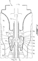
Fig. 2 is an enlarged cross-section of the engine shown inFig. 1 and illustrates first and second gear trains incorporated in the center cavity of the gas generator case between the HP compressor and the LP compressor to respectively interconnect the LP turbine to the LP compressor and the HP spool to an axially mounted accessory gearbox (AGB) driven through the center of the LP compressor; -
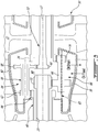
Fig. 3 is an enlarged cross-section view of the first and second gear trains and illustrates an oil line capacity of the case structure housing the gear trains, the case structure being formed by the compressor inner gaspath wall; and -
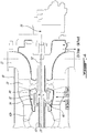
Fig. 4 is an enlarged cross-section view illustrating how the oil sump of the gear train module between the HP compressor and the LP compressor and that of the AGB are combined to provide a combined oil tank. -
Fig. 1 illustrates agas turbine engine 10 of a type preferably provided for use in subsonic flight, generally comprising in serial flow communication anair inlet 11, acompressor section 12 for pressurizing the air from theair inlet 11, acombustor 13 in which the compressed air is mixed with fuel and ignited for generating an annular stream of hot combustion gases, aturbine section 14 for extracting energy from the combustion gases, anexhaust outlet 15 through which the combustion gases exit theengine 10. Theengine 10 further has adrive output shaft 16 having a front end configured to drive a rotatable load (not shown). The rotatable load can, for instance, take the form of a propeller or a rotor, such as a helicopter main rotor. Depending on the intended use, theengine 10 can be configured as a turboprop engine or a turboshaft engine.Fig. 1 illustrates a turboprop configuration. Thegas turbine engine 10 has a centerline orlongitudinal center axis 17 about which the compressor and turbine rotors rotate. - The
gas turbine engine 10 has an axially extending central core which defines agaspath 18 through which gases flow, as depicted by flow arrows inFig. 1 . The exemplary embodiment shown inFig. 1 is a "reverse-flow" engine because gases flow through thegaspath 18 from theair inlet 11 at a rear portion thereof, to theexhaust outlet 15 at a front portion thereof. This is in contrast to "through-flow" gas turbine engines in which gases flow through the core of the engine from a front portion to a rear portion. The direction of the flow of gases through thegaspath 18 of theengine 10 disclosed herein can be better appreciated by considering that the gases flow through thegaspath 18 in the same direction D as the one along which an aircraft engine travels during flight. Stated differently, gases flow through theengine 10 from a rear end thereof towards theoutput shaft 16. - It will thus be appreciated that the expressions "forward" and "aft" used herein refer to the relative disposition of components of the
engine 10, in correspondence to the "forward" and "aft" directions of theengine 10 and aircraft including theengine 10 as defined with respect to the direction of travel. In the embodiment shown, a component of theengine 10 that is "forward" of another component is arranged within theengine 10 such that it is located closer to output shaft 16 (e.g. closer to the propeller in a turboprop application). Similarly, a component of theengine 10 that is "aft" of another component is arranged within theengine 10 such that it is further away from theoutput shaft 16. - Still referring to
Fig. 1 , theengine 10 has multiple spools which perform compression to pressurize the air received through theair inlet 11, and which extract energy from the combustion gases before they exit thegaspath 18 via theexhaust outlet 15. More particularly, the illustrated embodiment comprises a low pressure (LP)spool 20 and a high pressure (HP)spool 40 mounted for rotation about the engine central axis. The LP and HP spools 20, 40 are independently rotatable about thecentral axis 17. The term "spool" is herein intended to broadly refer to drivingly connected turbine and compressor rotors and is, thus, not limited to a compressor and turbine assembly on a single shaft. As will be seen hereinbelow, it also includes a rotary assembly with multiple shafts geared together. - The
LP spool 20 includes at least one component to compress the air that is part of thecompressor section 12, and at least one component to extract energy from the combustion gases that is part of theturbine section 14. More particularly, theLP spool 20 has alow pressure turbine 21, also known as a power turbine, which may include different number of stages (three stages in the illustrated embodiment), and which drives an LP compressor 22 (also referred to as a boost). Thelow pressure turbine 21 drives thelow pressure compressor 22, thereby causing theLP compressor 22 to pressurize incoming air from theair inlet 11. TheLP compressor 22 is disposed just forward of theair inlet 11. Both theLP turbine 21 and theLP compressor 22 are disposed along thecenter axis 17. In the depicted embodiment, both theLP turbine 21 and theLP compressor 22 include rotatable components having an axis of rotation that is coaxial with thecenter axis 17. It is understood that they can each include one or more stages depending upon the desired engine thermodynamic cycle. - The
LP turbine 21 is forward of theLP compressor 22. TheLP turbine 21 is also aft of theexhaust outlet 15. TheLP compressor 22 is forward of theair inlet 11. This arrangement of theLP turbine 21 and theLP compressor 22 provides for a reverse-flow engine 10 that has one or more LP compressor stages located at the rear of theengine 10, and which are driven by one or more low pressure turbine stages located at the front of theengine 10. - The
LP spool 20 further comprises an LP shaft 23 (also known as a power shaft) coaxial with thecenter axis 17 of theengine 10. TheLP turbine 21 is drivingly connected to theLP shaft 23. TheLP shaft 23 allows theLP turbine 21 to drive theLP compressor 22 during operation of theengine 10. As will be discussed in greater details hereinbelow, theLP shaft 23 may be drivingly connected to theLP compressor 22 via a gear train to allow theLP compressor 22 to run at a different rotational speed from theLP turbine 21. This can provide more flexibility in the selection of design points for theLP compressor 22 while at the same time allowing to drivingly connect an axially mounted accessory gear box (AGB) to theHP spool 40 centrally through theLP compressor 22, thereby minimizing the engine envelope in a direction radial from theengine axis 17. - It is understood that the
LP shaft 23 is not limited to the configuration depicted inFig. 1 . For instance, instead of being provided in the form of a one piece through shaft, it could be divided into serially interconnectable sections. Splines or other suitable connections could be provided between adjacent shaft sections to transfer torque from theLP turbine 21. - Still referring to
Fig. 1 , it can be appreciated that theLP shaft 23 also extends axially forwardly from theLP turbine 21 for driving theoutput shaft 16. TheLP shaft 23 is drivingly connected to theoutput shaft 16 via a suitable reduction gear box (RGB) 31. A rotatable load, a propeller (not shown) according to the illustrated example, is connectable to a front end of theoutput shaft 16. In this way, theLP turbine 21 can be used to drive the rotatable load (e.g. the propeller) at a reduced speed relative to the speed of theLP turbine 21. In such a configuration, during operation of theengine 10, theLP turbine 21 drives the rotatable load such that a rotational drive produced by theLP turbine 21 is transferred to the rotatable load via theLP shaft 23, theRGB 31 and theoutput shaft 16 coming out forwardly from theRGB 31. The rotatable load can therefore be any suitable component, or any combination of suitable components, that is capable of receiving the rotational drive from theLP turbine section 21. - The
RGB 31 processes and outputs the rotational drive transferred thereto from theLP turbine 21 via theLP shaft 23 through known gear reduction techniques. TheRGB 31 allows for the load (e.g. the propeller according to the illustrated turboprop example) to be driven at its optimal rotational speed, which is different from the rotational speed of theLP turbine 21. TheRGB 31 is axially mounted at the front end of the engine. TheRGB 31 has an input and an output axis parallel (coaxial in the illustrated embodiment) to thecentral axis 17 of theengine 10. - In an alternate embodiment where the
engine 10 is a turboshaft, the rotational load (which may include, but is not limited to, helicopter main rotor(s) and/or tail rotor(s), propeller(s) for a tilt-rotor aircraft, pump(s), generator(s), gas compressor(s), marine propeller(s), etc.) is driven by theLP turbine 21 via theRGB 31, or theRGB 31 may be omitted such that the output of theengine 10 is provided directly by theLP shaft 23. - The
LP shaft 23 with the portions thereof extending forward and aft of theLP turbine 21 provides theengine 10 with bidirectional drive. Modularity criteria for gas turbine engines may require the use of distinct shaft sections in opposed axial directions from theLP turbine 21. The LP shaft sections may be directly or indirectly connected together. Alternately, theLP shaft 23 can be integral with a first segment of the LP shaft extending axially between theLP compressor 22 and theLP turbine 21, and a second segment extending between the rotatable load and theLP turbine 21. Whether theLP shaft 23 is integral or segmented, theLP turbine 21 provides rotational drive outputted at each end of theLP shaft 23. - In light of the preceding, it can be appreciated that the
LP turbine 21 drives both the rotatable load and theLP compressor 22. Furthermore, the rotatable load, when mounted to theengine 10, and theLP compressor 22 are disposed on opposite ends of theLP turbine 21. It can thus be appreciated that one or more low pressure turbine stages are used to drive elements in front of the LP turbine (e.g. propeller,RGB 31, etc.) as well as to drive elements to the rear of the LP turbine (e.g. LP compressor 22). This configuration of theLP turbine 21 allows it to simultaneously drive the rotatable load and theLP compressor 22. - Still referring to
Fig. 1 , theHP spool 40 has at least one component to compress the air that is part of thecompressor section 12, and at least one component to extract energy from the combustion gases that is part of theturbine section 14. TheHP spool 40 is also disposed along thecenter axis 17 and includes an HP turbine 41 (also referred to as the compressor turbine) drivingly engaged (e.g. directly connected) to anHP compressor 42 by anHP shaft 43 rotating independently of theLP shaft 23. In the illustrated embodiment, theHP shaft 43 is a hollow shaft which rotates around theLP shaft 23. That is theLP shaft 23 extends axially through theHP shaft 43. Similarly to theLP turbine 21 and theLP compressor 22, theHP turbine 41 and theHP compressor 42 can each include one or more stages of rotors, depending upon the desired engine thermodynamic cycle, for example. In the depicted embodiment, theHP compressor 42 includes acentrifugal compressor 42a or impeller and anaxial compressor 42b, both of which are driven by theHP turbine 41. During operation of theengine 10, torque is transferred fromHP turbine 41 to theHP compressor 42 viaHP shaft 43. - In the illustrated reverse flow engine configuration, the
HP turbine 41 is aft of theLP turbine 21, and forward of thecombustor 13. TheHP compressor 42 is aft of thecombustor 13, and forward of theLP compressor 22. From this arrangement of theHP turbine 41 and theHP compressor 42, it can be appreciated that during operation of theengine 10, theLP compressor 22 driven by theLP turbine 21 feeds pressurized air to theHP compressor 42. Therefore, the pressurized air flow produced by theLP compressor 22 is provided to theHP compressor 42 and contributes to the work of both theLP turbine 21 and theHP turbine 41. This arrangement provides for a boosted reverse flow engine. - It can thus be appreciated that the presence of the above-described LP and HP spools 20, 40 provides the
engine 10 with a "split compressor" arrangement. More particularly, some of the work required to compress the incoming air is transferred from theHP compressor 42 to theLP compressor 22. In other words, some of the compression work is transferred from theHP turbine 41 to the moreefficient LP turbine 21. This transfer of work may contribute to higher pressure ratios while maintaining a relatively small number of rotors. In a particular embodiment, higher pressure ratios allow for higher power density, better engine specific fuel consumption (SFC), and a lower turbine inlet temperature (sometimes referred to as "T4") for a given power. These factors can contribute to a lower overall weight for theengine 10. The transfer of compression work from theHP compressor 42 to theLP compressor 22 contrasts with some conventional reverse-flow engines, in which the high pressure compressor (and thus the high pressure turbine) perform all of the compression work. - In light of the preceding, it can be appreciated that the
LP turbine 21 is the "low-speed" and "low pressure" turbine section when compared to theHP turbine 41. TheLP turbine 21 is sometimes referred to as the "power turbine". The turbine rotors of theHP turbine 41 spin at a higher rotational speed than the turbine rotors of theLP turbine 21 given the closer proximity of theHP turbine 41 to the outlet of thecombustor 13. Consequently, the compressor rotors of theHP compressor 42 may rotate at a higher rotational speed than the compressor rotors of theLP compressor 22. - The
HP turbine 41 and theHP compressor 42 can have any suitable mechanical arrangement to achieve the above-described split compressor functionality. For example, and as shown inFig. 1 , theHP shaft 43 extends concentrically about theLP shaft 23 and is independently rotatable relative thereto. The relative rotation between theHP shaft 43 and theLP shaft 23 allow theshafts HP compressor 42 and theLP compressor 22 to rotate at different rotational speeds. TheHP shaft 43 can be mechanically supported by theLP shaft 23 using bearings or the like. - Still referring to the embodiment shown in
Fig. 1 , theengine 10 also includes an accessory gearbox (AGB) 50. TheAGB 50 receives a rotational input from theHP spool 40 and, in turn, drives accessories (e.g. fuel pump, starter-generator, oil pump, scavenge pump, etc.) that contribute to the functionality of theengine 10. TheAGB 50 can be designed with side-facing accessories, top-facing accessories, or rear-facing accessories depending on the installation needs. - According to the illustrated embodiment, the
AGB 50 is concentrically mounted axially aft of theLP compressor 22 as an axial extension of the engine envelope. The axial positioning of theAGB 50 allows minimizing the diameter of the envelope of the engine as compared to a split compressor or boosted engine having the AGB mounted on a side of the engine and connected to the HP spool via a tower shaft. In the illustrated embodiment, the AGB is accommodated within the envelope of the engine in a plane normal to thecentral axis 17. - In the illustrated embodiment, the AGB input drive axis is coaxial to the LP compressor centerline and the engine
central axis 17. By so aligning the input axis of theAGB 50 relative to the LP compressor centerline, the drive input to theAGB 50 can be provided centrally through the center of theLP compressor 22, thereby eliminating the need for a tower shaft and an externally mounted gear arrangement. However, unlike conventional reverse flow engines (like the well-known PT6 engine manufactured by Pratt & Whitney Canada), which do not include a compressor boost, the presence of theLP compressor 22 axially between theHP compressor 42 and theAGB 50 physically interferes with the connection of theAGB 50 with theHP spool 40. In the illustrated embodiment, this particular problem is overcome by passing theinput drive shaft 52 of theAGB 50 centrally through theLP compressor 22. As best shown inFig. 2 , theAGB input shaft 52 extends along the enginecentral axis 17 through the central bore of theLP compressor 22. Afirst gear train 54 is provided for drivingly connecting theAGB input shaft 52 to theHP compressor 42. In the illustrated embodiment, thefirst gear train 54 comprises a gearedshaft 56 having afirst gear 58 in meshing engagement with acorresponding gear 60 at a distal end of theAGB drive shaft 52 and asecond gear 62 in meshing engagement with acorresponding gear 64 at the rear end of theHP shaft 43 orHP compressor 42. To physically permit this gear drive connection between theAGB input shaft 52 and theHP spool 40 through the center of theLP compressor 22, a discontinuity between theLP shaft 23 and theLP compressor 22 is provided and theLP shaft 23 is drivingly connected to theLP compressor 22 via asecond gear train 66. Indeed, if theLP shaft 23 was to extend continuously to theLP compressor 22, theAGB input shaft 52 could not be geared to the gearedshaft 56, which is disposed radially outwardly relative to theLP shaft 23. - According to the illustrated embodiment, the
second gear train 66 comprises a gearedshaft 68 comprising afirst gear 70 in meshing engagement with acorresponding gear 72 at the rear end of theLP shaft 23 and asecond gear 74 in meshing engagement with acorresponding gear 76 on a hub portion projecting axially forwardly from theLP compressor 22. As mentioned herein above, the gear connection between theLP turbine 21 and theLP compressor 22 is also advantageous in that it allows to drive the LP compressor at a different speed than the LP turbine. It can thus allow for overall thermodynamic cycle performance improvement. - In the illustrated embodiment, the first and
second gear trains cavity 80 of the gas generator case 81 (Figs. 1 and4 ) radially inwardly of thegaspath 18 axially between the HP andLP compressors central cavity 80 is circumscribed by the compressorinner gaspath wall 82. This provides for a compact arrangement. The use of theinner gaspath wall 82 to house thegear trains - The
inner gaspath wall 82 in addition to forming a flow boundary surface for thegaspath 18, thus, also acts as a casing for housing the first andsecond gear trains gear trains inner gaspath wall 82 also provides a sump to contain the oil required to lubricate the gears.Broken line 83 inFig. 3 is representative of the oil level that may be contained in the sump. The oil feed and return lines may be passed through a hollow strut or vane extending radially through the gaspath, as depicted by flow arrows inFig. 3 . - The
central cavity 80 may be formed by the gas generator case and the inlet case of theengine 10. In this way access to thegear trains engine 10. - As shown in
Fig. 4 , thecentral cavity 80 housing thegear trains AGB 50. Oil from thecavity 80 can flow into the oil chamber of the AGB and vice versa. That is the oil reservoir of both modules (1- the first and second gear trains and 2- the AGB) on opposed sides of the LP compressor are combined using their own individual sump capacity. The oil from both modules can travel axially centrally through theLP compressor 22 and be collected in the sump of the other module. - It is understood that the first and
second gear trains Figs. 1 and2 is given for illustrative purposes only. For instance, the output of the first and second gear trains could be asymmetric relative to the rotation axis of the LP and HP spools. In the illustrated embodiment, the output of the first and second gear trains is concentric to theaxis 17. - It can thus be appreciated that at least some of the embodiments of the
engine 10 disclosed herein provide a mechanical architecture of turbomachinery that allows for a split compressor system in a compact PT6 type configuration. Such a split compressor engine in a reverse flow or through flow configuration may be used for aircraft nose installations, as well as for wing installations. The gear trains 54, 66 eliminate the need for a tower shaft an externally mounted gear train for connecting theAGB 50 to theHP spool 40. In this way not shaft has to be passed across the gaspath to drivingly connect the HP spool to the AGB, thereby avoiding performances losses. The compressor aerodynamics can be improved by eliminating the service strut typically used to pass the tower shaft. The engine weight may be reduced by eliminating the need of an upstream transfer case. The position of the hardware used to build the gear trains may be designed for an optimal clearance from the LP rotor center. - The above description is meant to be exemplary only, and one skilled in the art will recognize that changes may be made to the embodiments described without departing from the scope of the invention disclosed. Modifications which fall within the scope of the present invention will be apparent to those skilled in the art, in light of a review of this disclosure, and such modifications are intended to fall within the appended claims.
Claims (15)
- A multi-spool gas turbine engine (10) comprising:a low pressure (LP) spool (20);a high pressure (HP) spool (40) fluidly connected to the LP spool (20) via a gaspath (18), the LP spool (20) and the HP spool (40) being mounted for rotation about a central axis (17);the LP spool (20) comprising an LP compressor (22) and an LP turbine (21), the HP spool (40) comprising an HP turbine (41) and an HP compressor (42); andan accessory gear box (AGB) (50) drivingly connected to the HP spool (40), the LP compressor (22) being axially positioned between the HP compressor (42) and the AGB (50) and drivingly connected to the LP turbine (21) via a gear train (66) positioned axially between the HP compressor (42) and the LP compressor (22) and radially inwardly from the gaspath (18).
- The multi-spool gas turbine engine (10) defined in claim 1, wherein the LP turbine (21) is drivingly mounted to an LP shaft (23) extending axially along the central axis (17) within an HP shaft (43) connecting the HP turbine (41) to the HP compressor (42), the LP shaft (23) having one end thereof projecting axially out of the HP shaft (43), said gear train (66) being provided at said one end of the LP shaft (23).
- The multi-spool gas turbine engine (10) defined in claim 1 or 2, wherein the gear train (66) is contained within a central chamber (80) circumscribed by an inner gaspath wall (82) between the HP compressor (42) and the LP compressor (22).
- The multi-spool gas turbine engine (10) defined in any preceding claim, wherein the engine (10) is an aircraft engine (10), the AGB (50) is aft of the LP compressor (22) along an intended direction of travel (D) of the aircraft engine (10), the LP compressor (22) is aft of the HP compressor (42), the HP compressor (42) is aft of the HP turbine (41), the HP turbine (41) is aft of the LP turbine (21), the LP turbine (21) is drivingly connected to an output drive shaft (16) having a front end configured to drivingly engage a rotatable load, and the LP turbine (21) being aft of the front end of the output drive shaft (16).
- The multi-spool gas turbine engine (10) defined in claim 4, wherein a further gear train (54) is provided between the HP compressor (42) and the LP compressor (22), the further gear train (54) interconnecting the HP spool (40) to an input drive shaft (52) of the AGB (50), the input drive shaft (16) extending axially through a central bore of the LP compressor (22).
- A reverse flow gas turbine engine (10), comprising:an output drive shaft (16) having a front end configurable to drivingly engage a rotatable load;a low pressure (LP) spool (20) including an LP turbine (21) drivingly engaged to the output drive shaft (16), and an LP compressor (22) drivingly connected to the LP turbine (21) via a gear train (66), the LP turbine (21) disposed forward of the LP compressor (22) relative to a front end of the output drive shaft (16); anda high pressure HP spool (40) including an HP turbine (41) and an HP compressor (42) drivingly engaged to an HP shaft (43) rotatable independently of the LP spool (20), the HP compressor (42) disposed forward of the LP compressor (22) and in fluid communication therewith via a gaspath (18), and the HP turbine (41) disposed aft of the LP turbine (21) and in fluid communication therewith through said gaspath (18), wherein the gear train (66) coupling the LP compressor (22) to the LP turbine (21) is disposed between the LP compressor (22) and the HP compressor (42) and radially inwardly from the gaspath (18).
- The reverse flow gas turbine engine (10) defined in claim 6, further comprising an accessory gearbox (AGB) (50), the AGB (50) being mounted aft of the LP compressor (22).
- The reverse flow gas turbine engine (10) defined in claim 7, wherein the AGB (50) has an input shaft (52) extending through a central bore of the LP compressor (22), the input shaft (52) being drivingly connected to the HP spool (40) via a further gear train (54), the gear train (66) and the further gear train (54) being housed in a same chamber (80) circumscribed by an inner gaspath wall (82) of the gaspath (18), and the chamber (80) in which are disposed the gear train (66) and the further gear train (54) is in fluid flow communication with an oil chamber of the AGB (50) axially through the center of the LP compressor (22).
- A multi-spool gas turbine engine (10) comprising:a low pressure (LP) spool (20);a high pressure (HP) spool (40) fluidly connected to the LP spool by a gaspath (18) , the LP spool (20) comprising an LP compressor (22) and an LP turbine (21), the HP spool (40) comprising an HP turbine (41) and an HP compressor (42);an accessory gear box (AGB) (50), the LP compressor (22) positioned between the HP compressor (42) and the AGB (50); andfirst and second gear trains (66, 54) positioned between the HP compressor (42) and the LP compressor (22) and radially inwardly from the gaspath (18), the first gear train (66) coupling the LP turbine (21) to the LP compressor (22), the second gear train (54) coupling the HP spool (40) to the AGB (50).
- The multi-spool gas turbine engine (10) defined in claim 9, wherein the AGB (50) has an input shaft (52), the input shaft (52) extending through a central bore of the LP compressor (22) into meshing engagement with a gear (58) of the second gear train (54).
- The multi-spool gas turbine engine (10) defined in claim 9 or 10, wherein a gear ratio of the first gear train (66) is selected to permit the LP compressor (22) to rotate at a different speed than the LP turbine (21).
- The multi-spool gas turbine engine (10) defined in any of claims 9 to 11, wherein the engine (10) is an aircraft engine (10) having a reverse flow configuration including an air inlet (11) disposed aft of the LP compressor (22) along an intended direction (D) of travel of the aircraft engine (10), the AGB (50) is disposed aft of the air inlet (11), and the aircraft engine (10) is optionally a turboprop engine (10) including a reduction gear box (31) drivingly connected to the LP turbine (21), the reduction gear box (31) disposed forward of the LP turbine (21).
- The multi-spool gas turbine engine (10) defined in any of claims 9 to 12, wherein the gaspath (18) has an inner gaspath wall (82), the first and second gear trains (66, 54) are contained in a central chamber (80) circumscribed by the inner gaspath wall (82), the central chamber (80) contains oil, and the central chamber (80) is optionally fluidly connected to an oil chamber of the AGB (50), thereby providing for a combined oil sump for the AGB (50) and the first and second gear trains (66, 54).
- The multi-spool gas turbine engine (10) defined in any of claims 9 to 13, wherein the LP spool (20) comprises an LP shaft (23), the LP shaft (23) having an end disposed between the HP compressor (42) and the LP compressor (22), said end of the LP shaft (23) providing a drive input to the first gear train (66).
- The multi-spool gas turbine engine (10) defined in any of claims 9 to 14, wherein the gaspath (18) has an inner gaspath wall (82), the inner gaspath wall (82) providing support to the first and second gear trains (66, 54).
Applications Claiming Priority (11)
| Application Number | Priority Date | Filing Date | Title |
|---|---|---|---|
| US201662363949P | 2016-07-19 | 2016-07-19 | |
| US201662363952P | 2016-07-19 | 2016-07-19 | |
| US201662363955P | 2016-07-19 | 2016-07-19 | |
| US201662363956P | 2016-07-19 | 2016-07-19 | |
| US201662363947P | 2016-07-19 | 2016-07-19 | |
| US15/384,959 US10883424B2 (en) | 2016-07-19 | 2016-12-20 | Multi-spool gas turbine engine architecture |
| US15/407,445 US10767567B2 (en) | 2016-07-19 | 2017-01-17 | Multi-spool gas turbine engine architecture |
| US15/407,414 US10458340B2 (en) | 2016-07-19 | 2017-01-17 | Turbine shaft power take-off |
| US15/407,423 US10393027B2 (en) | 2016-07-19 | 2017-01-17 | Gas turbine engine shaft architecture and associated method of disassembly |
| US15/407,439 US10690061B2 (en) | 2016-07-19 | 2017-01-17 | Gear train architecture for a multi-spool gas turbine engine |
| EP17182094.7A EP3309371B1 (en) | 2016-07-19 | 2017-07-19 | Gear train architecture for a multi-spool gas turbine engine |
Related Parent Applications (1)
| Application Number | Title | Priority Date | Filing Date |
|---|---|---|---|
| EP17182094.7A Division EP3309371B1 (en) | 2016-07-19 | 2017-07-19 | Gear train architecture for a multi-spool gas turbine engine |
Publications (2)
| Publication Number | Publication Date |
|---|---|
| EP3597885A1 true EP3597885A1 (en) | 2020-01-22 |
| EP3597885B1 EP3597885B1 (en) | 2022-04-20 |
Family
ID=59381171
Family Applications (7)
| Application Number | Title | Priority Date | Filing Date |
|---|---|---|---|
| EP17182076.4A Active EP3273031B1 (en) | 2016-07-19 | 2017-07-19 | Gas turbine engine shaft architecture and associated method of disassembly |
| EP17182087.1A Active EP3273032B1 (en) | 2016-07-19 | 2017-07-19 | A multi-spool gas turbine engine architecture |
| EP19193921.4A Active EP3597885B1 (en) | 2016-07-19 | 2017-07-19 | Gear train architecture for a multi-spool gas turbine engine |
| EP17182102.8A Active EP3273034B1 (en) | 2016-07-19 | 2017-07-19 | A multi-spool gas turbine engine architecture |
| EP19193794.5A Active EP3597884B1 (en) | 2016-07-19 | 2017-07-19 | A multi-spool gas turbine engine architecture |
| EP17182096.2A Active EP3273033B1 (en) | 2016-07-19 | 2017-07-19 | Turbine shaft power take-off |
| EP19183868.9A Active EP3572638B1 (en) | 2016-07-19 | 2017-07-19 | Turboprop engine |
Family Applications Before (2)
| Application Number | Title | Priority Date | Filing Date |
|---|---|---|---|
| EP17182076.4A Active EP3273031B1 (en) | 2016-07-19 | 2017-07-19 | Gas turbine engine shaft architecture and associated method of disassembly |
| EP17182087.1A Active EP3273032B1 (en) | 2016-07-19 | 2017-07-19 | A multi-spool gas turbine engine architecture |
Family Applications After (4)
| Application Number | Title | Priority Date | Filing Date |
|---|---|---|---|
| EP17182102.8A Active EP3273034B1 (en) | 2016-07-19 | 2017-07-19 | A multi-spool gas turbine engine architecture |
| EP19193794.5A Active EP3597884B1 (en) | 2016-07-19 | 2017-07-19 | A multi-spool gas turbine engine architecture |
| EP17182096.2A Active EP3273033B1 (en) | 2016-07-19 | 2017-07-19 | Turbine shaft power take-off |
| EP19183868.9A Active EP3572638B1 (en) | 2016-07-19 | 2017-07-19 | Turboprop engine |
Country Status (2)
| Country | Link |
|---|---|
| EP (7) | EP3273031B1 (en) |
| PL (7) | PL3273031T3 (en) |
Families Citing this family (10)
| Publication number | Priority date | Publication date | Assignee | Title |
|---|---|---|---|---|
| US11415063B2 (en) | 2016-09-15 | 2022-08-16 | Pratt & Whitney Canada Corp. | Reverse-flow gas turbine engine |
| US10883424B2 (en) | 2016-07-19 | 2021-01-05 | Pratt & Whitney Canada Corp. | Multi-spool gas turbine engine architecture |
| US11035293B2 (en) | 2016-09-15 | 2021-06-15 | Pratt & Whitney Canada Corp. | Reverse flow gas turbine engine with offset RGB |
| US10465611B2 (en) | 2016-09-15 | 2019-11-05 | Pratt & Whitney Canada Corp. | Reverse flow multi-spool gas turbine engine with aft-end accessory gearbox drivingly connected to both high pressure spool and low pressure spool |
| US10815899B2 (en) | 2016-11-15 | 2020-10-27 | Pratt & Whitney Canada Corp. | Gas turbine engine accessories arrangement |
| US10808624B2 (en) * | 2017-02-09 | 2020-10-20 | Pratt & Whitney Canada Corp. | Turbine rotor with low over-speed requirements |
| US10746188B2 (en) | 2017-03-14 | 2020-08-18 | Pratt & Whitney Canada Corp. | Inter-shaft bearing connected to a compressor boost system |
| CN110821677A (en) | 2018-08-08 | 2020-02-21 | 普拉特 - 惠特尼加拿大公司 | Multi-engine system and method |
| US11174916B2 (en) | 2019-03-21 | 2021-11-16 | Pratt & Whitney Canada Corp. | Aircraft engine reduction gearbox |
| US11268453B1 (en) | 2021-03-17 | 2022-03-08 | Pratt & Whitney Canada Corp. | Lubrication system for aircraft engine reduction gearbox |
Citations (3)
| Publication number | Priority date | Publication date | Assignee | Title |
|---|---|---|---|---|
| WO2005061873A1 (en) * | 2003-12-22 | 2005-07-07 | Pratt & Whitney Canada Corp. | Gas turbine engine architecture |
| EP2728140A2 (en) * | 2012-10-31 | 2014-05-07 | Rolls-Royce Deutschland Ltd & Co KG | Booster assembly for gas turbine engine comprising a gearing |
| WO2015122948A2 (en) * | 2013-12-05 | 2015-08-20 | United Technologies Corporation | Gas turbine engines with intercoolers and recuperators |
Family Cites Families (11)
| Publication number | Priority date | Publication date | Assignee | Title |
|---|---|---|---|---|
| GB603283A (en) * | 1946-06-27 | 1948-06-11 | Power Jets Res & Dev Ltd | Improvements in or relating to internal combustion turbine power plants |
| US4611464A (en) * | 1984-05-02 | 1986-09-16 | United Technologies Corporation | Rotor assembly for a gas turbine engine and method of disassembly |
| US20060137355A1 (en) * | 2004-12-27 | 2006-06-29 | Pratt & Whitney Canada Corp. | Fan driven emergency generator |
| US20080075590A1 (en) * | 2006-09-27 | 2008-03-27 | Thomas Ory Moniz | Gas turbine engine assembly and method of assembling same |
| WO2008045068A1 (en) * | 2006-10-12 | 2008-04-17 | United Technologies Corporation | Turbofan engine with variable area fan nozzle and low spool generator for emergency power generation and method for providing emergency power. |
| GB0903423D0 (en) * | 2009-03-02 | 2009-04-08 | Rolls Royce Plc | Variable drive gas turbine engine |
| US8176725B2 (en) * | 2009-09-09 | 2012-05-15 | United Technologies Corporation | Reversed-flow core for a turbofan with a fan drive gear system |
| JP5016706B2 (en) * | 2009-11-04 | 2012-09-05 | 川崎重工業株式会社 | Aircraft starter generator |
| US20140252160A1 (en) * | 2013-03-07 | 2014-09-11 | United Technologies Corporation | Reverse flow gas turbine engine removable core |
| IL228274A (en) * | 2013-09-03 | 2016-10-31 | Israel Aerospace Ind Ltd | Turbofan engine and method for converting a turbofan engine |
| US9890846B2 (en) * | 2014-12-08 | 2018-02-13 | General Electric Company | Gearbox with sealed accessory vent |
-
2017
- 2017-07-19 PL PL17182076T patent/PL3273031T3/en unknown
- 2017-07-19 PL PL19183868T patent/PL3572638T3/en unknown
- 2017-07-19 PL PL17182102T patent/PL3273034T3/en unknown
- 2017-07-19 PL PL17182087T patent/PL3273032T3/en unknown
- 2017-07-19 EP EP17182076.4A patent/EP3273031B1/en active Active
- 2017-07-19 EP EP17182087.1A patent/EP3273032B1/en active Active
- 2017-07-19 PL PL19193921.4T patent/PL3597885T3/en unknown
- 2017-07-19 PL PL17182096T patent/PL3273033T3/en unknown
- 2017-07-19 EP EP19193921.4A patent/EP3597885B1/en active Active
- 2017-07-19 PL PL19193794.5T patent/PL3597884T3/en unknown
- 2017-07-19 EP EP17182102.8A patent/EP3273034B1/en active Active
- 2017-07-19 EP EP19193794.5A patent/EP3597884B1/en active Active
- 2017-07-19 EP EP17182096.2A patent/EP3273033B1/en active Active
- 2017-07-19 EP EP19183868.9A patent/EP3572638B1/en active Active
Patent Citations (3)
| Publication number | Priority date | Publication date | Assignee | Title |
|---|---|---|---|---|
| WO2005061873A1 (en) * | 2003-12-22 | 2005-07-07 | Pratt & Whitney Canada Corp. | Gas turbine engine architecture |
| EP2728140A2 (en) * | 2012-10-31 | 2014-05-07 | Rolls-Royce Deutschland Ltd & Co KG | Booster assembly for gas turbine engine comprising a gearing |
| WO2015122948A2 (en) * | 2013-12-05 | 2015-08-20 | United Technologies Corporation | Gas turbine engines with intercoolers and recuperators |
Also Published As
| Publication number | Publication date |
|---|---|
| EP3273033B1 (en) | 2020-12-02 |
| EP3273031B1 (en) | 2019-07-03 |
| EP3273034A1 (en) | 2018-01-24 |
| EP3597885B1 (en) | 2022-04-20 |
| PL3273034T3 (en) | 2020-06-15 |
| PL3273033T3 (en) | 2021-06-28 |
| EP3597884A1 (en) | 2020-01-22 |
| PL3273031T3 (en) | 2019-12-31 |
| EP3273033A1 (en) | 2018-01-24 |
| EP3597884B1 (en) | 2022-04-20 |
| EP3572638A1 (en) | 2019-11-27 |
| EP3572638B1 (en) | 2020-12-23 |
| EP3273032A2 (en) | 2018-01-24 |
| EP3273032B1 (en) | 2019-08-28 |
| PL3572638T3 (en) | 2021-07-05 |
| PL3597885T3 (en) | 2022-07-18 |
| PL3273032T3 (en) | 2020-04-30 |
| EP3273034B1 (en) | 2020-01-01 |
| EP3273031A1 (en) | 2018-01-24 |
| PL3597884T3 (en) | 2022-08-29 |
| EP3273032A3 (en) | 2018-04-18 |
Similar Documents
| Publication | Publication Date | Title |
|---|---|---|
| EP3309371B1 (en) | Gear train architecture for a multi-spool gas turbine engine | |
| US11773785B2 (en) | Reverse-flow gas turbine engine | |
| EP3597885B1 (en) | Gear train architecture for a multi-spool gas turbine engine | |
| US11041443B2 (en) | Multi-spool gas turbine engine architecture | |
| EP3321488B1 (en) | Gas turbine engine accessories arrangement | |
| EP3296541B1 (en) | Reverse flow gas turbine engine with offset reduction gearbox | |
| CA2970389A1 (en) | Gear train architecture for a multi-spool gas turbine engine |
Legal Events
| Date | Code | Title | Description |
|---|---|---|---|
| PUAI | Public reference made under article 153(3) epc to a published international application that has entered the european phase |
Free format text: ORIGINAL CODE: 0009012 |
|
| STAA | Information on the status of an ep patent application or granted ep patent |
Free format text: STATUS: THE APPLICATION HAS BEEN PUBLISHED |
|
| AC | Divisional application: reference to earlier application |
Ref document number: 3309371 Country of ref document: EP Kind code of ref document: P |
|
| AK | Designated contracting states |
Kind code of ref document: A1 Designated state(s): AL AT BE BG CH CY CZ DE DK EE ES FI FR GB GR HR HU IE IS IT LI LT LU LV MC MK MT NL NO PL PT RO RS SE SI SK SM TR |
|
| STAA | Information on the status of an ep patent application or granted ep patent |
Free format text: STATUS: REQUEST FOR EXAMINATION WAS MADE |
|
| 17P | Request for examination filed |
Effective date: 20200721 |
|
| RBV | Designated contracting states (corrected) |
Designated state(s): AL AT BE BG CH CY CZ DE DK EE ES FI FR GB GR HR HU IE IS IT LI LT LU LV MC MK MT NL NO PL PT RO RS SE SI SK SM TR |
|
| GRAP | Despatch of communication of intention to grant a patent |
Free format text: ORIGINAL CODE: EPIDOSNIGR1 |
|
| STAA | Information on the status of an ep patent application or granted ep patent |
Free format text: STATUS: GRANT OF PATENT IS INTENDED |
|
| INTG | Intention to grant announced |
Effective date: 20211122 |
|
| GRAS | Grant fee paid |
Free format text: ORIGINAL CODE: EPIDOSNIGR3 |
|
| GRAA | (expected) grant |
Free format text: ORIGINAL CODE: 0009210 |
|
| STAA | Information on the status of an ep patent application or granted ep patent |
Free format text: STATUS: THE PATENT HAS BEEN GRANTED |
|
| AC | Divisional application: reference to earlier application |
Ref document number: 3309371 Country of ref document: EP Kind code of ref document: P |
|
| AK | Designated contracting states |
Kind code of ref document: B1 Designated state(s): AL AT BE BG CH CY CZ DE DK EE ES FI FR GB GR HR HU IE IS IT LI LT LU LV MC MK MT NL NO PL PT RO RS SE SI SK SM TR |
|
| REG | Reference to a national code |
Ref country code: GB Ref legal event code: FG4D |
|
| REG | Reference to a national code |
Ref country code: CH Ref legal event code: EP |
|
| REG | Reference to a national code |
Ref country code: IE Ref legal event code: FG4D |
|
| REG | Reference to a national code |
Ref country code: DE Ref legal event code: R096 Ref document number: 602017056419 Country of ref document: DE |
|
| REG | Reference to a national code |
Ref country code: AT Ref legal event code: REF Ref document number: 1485310 Country of ref document: AT Kind code of ref document: T Effective date: 20220515 |
|
| REG | Reference to a national code |
Ref country code: LT Ref legal event code: MG9D |
|
| REG | Reference to a national code |
Ref country code: NL Ref legal event code: MP Effective date: 20220420 |
|
| REG | Reference to a national code |
Ref country code: AT Ref legal event code: MK05 Ref document number: 1485310 Country of ref document: AT Kind code of ref document: T Effective date: 20220420 |
|
| PG25 | Lapsed in a contracting state [announced via postgrant information from national office to epo] |
Ref country code: NL Free format text: LAPSE BECAUSE OF FAILURE TO SUBMIT A TRANSLATION OF THE DESCRIPTION OR TO PAY THE FEE WITHIN THE PRESCRIBED TIME-LIMIT Effective date: 20220420 |
|
| PG25 | Lapsed in a contracting state [announced via postgrant information from national office to epo] |
Ref country code: SE Free format text: LAPSE BECAUSE OF FAILURE TO SUBMIT A TRANSLATION OF THE DESCRIPTION OR TO PAY THE FEE WITHIN THE PRESCRIBED TIME-LIMIT Effective date: 20220420 Ref country code: PT Free format text: LAPSE BECAUSE OF FAILURE TO SUBMIT A TRANSLATION OF THE DESCRIPTION OR TO PAY THE FEE WITHIN THE PRESCRIBED TIME-LIMIT Effective date: 20220822 Ref country code: NO Free format text: LAPSE BECAUSE OF FAILURE TO SUBMIT A TRANSLATION OF THE DESCRIPTION OR TO PAY THE FEE WITHIN THE PRESCRIBED TIME-LIMIT Effective date: 20220720 Ref country code: LT Free format text: LAPSE BECAUSE OF FAILURE TO SUBMIT A TRANSLATION OF THE DESCRIPTION OR TO PAY THE FEE WITHIN THE PRESCRIBED TIME-LIMIT Effective date: 20220420 Ref country code: HR Free format text: LAPSE BECAUSE OF FAILURE TO SUBMIT A TRANSLATION OF THE DESCRIPTION OR TO PAY THE FEE WITHIN THE PRESCRIBED TIME-LIMIT Effective date: 20220420 Ref country code: GR Free format text: LAPSE BECAUSE OF FAILURE TO SUBMIT A TRANSLATION OF THE DESCRIPTION OR TO PAY THE FEE WITHIN THE PRESCRIBED TIME-LIMIT Effective date: 20220721 Ref country code: FI Free format text: LAPSE BECAUSE OF FAILURE TO SUBMIT A TRANSLATION OF THE DESCRIPTION OR TO PAY THE FEE WITHIN THE PRESCRIBED TIME-LIMIT Effective date: 20220420 Ref country code: ES Free format text: LAPSE BECAUSE OF FAILURE TO SUBMIT A TRANSLATION OF THE DESCRIPTION OR TO PAY THE FEE WITHIN THE PRESCRIBED TIME-LIMIT Effective date: 20220420 Ref country code: BG Free format text: LAPSE BECAUSE OF FAILURE TO SUBMIT A TRANSLATION OF THE DESCRIPTION OR TO PAY THE FEE WITHIN THE PRESCRIBED TIME-LIMIT Effective date: 20220720 Ref country code: AT Free format text: LAPSE BECAUSE OF FAILURE TO SUBMIT A TRANSLATION OF THE DESCRIPTION OR TO PAY THE FEE WITHIN THE PRESCRIBED TIME-LIMIT Effective date: 20220420 |
|
| PG25 | Lapsed in a contracting state [announced via postgrant information from national office to epo] |
Ref country code: RS Free format text: LAPSE BECAUSE OF FAILURE TO SUBMIT A TRANSLATION OF THE DESCRIPTION OR TO PAY THE FEE WITHIN THE PRESCRIBED TIME-LIMIT Effective date: 20220420 Ref country code: LV Free format text: LAPSE BECAUSE OF FAILURE TO SUBMIT A TRANSLATION OF THE DESCRIPTION OR TO PAY THE FEE WITHIN THE PRESCRIBED TIME-LIMIT Effective date: 20220420 Ref country code: IS Free format text: LAPSE BECAUSE OF FAILURE TO SUBMIT A TRANSLATION OF THE DESCRIPTION OR TO PAY THE FEE WITHIN THE PRESCRIBED TIME-LIMIT Effective date: 20220820 |
|
| REG | Reference to a national code |
Ref country code: DE Ref legal event code: R097 Ref document number: 602017056419 Country of ref document: DE |
|
| PG25 | Lapsed in a contracting state [announced via postgrant information from national office to epo] |
Ref country code: SM Free format text: LAPSE BECAUSE OF FAILURE TO SUBMIT A TRANSLATION OF THE DESCRIPTION OR TO PAY THE FEE WITHIN THE PRESCRIBED TIME-LIMIT Effective date: 20220420 Ref country code: SK Free format text: LAPSE BECAUSE OF FAILURE TO SUBMIT A TRANSLATION OF THE DESCRIPTION OR TO PAY THE FEE WITHIN THE PRESCRIBED TIME-LIMIT Effective date: 20220420 Ref country code: RO Free format text: LAPSE BECAUSE OF FAILURE TO SUBMIT A TRANSLATION OF THE DESCRIPTION OR TO PAY THE FEE WITHIN THE PRESCRIBED TIME-LIMIT Effective date: 20220420 Ref country code: EE Free format text: LAPSE BECAUSE OF FAILURE TO SUBMIT A TRANSLATION OF THE DESCRIPTION OR TO PAY THE FEE WITHIN THE PRESCRIBED TIME-LIMIT Effective date: 20220420 Ref country code: DK Free format text: LAPSE BECAUSE OF FAILURE TO SUBMIT A TRANSLATION OF THE DESCRIPTION OR TO PAY THE FEE WITHIN THE PRESCRIBED TIME-LIMIT Effective date: 20220420 |
|
| PLBE | No opposition filed within time limit |
Free format text: ORIGINAL CODE: 0009261 |
|
| STAA | Information on the status of an ep patent application or granted ep patent |
Free format text: STATUS: NO OPPOSITION FILED WITHIN TIME LIMIT |
|
| PG25 | Lapsed in a contracting state [announced via postgrant information from national office to epo] |
Ref country code: MC Free format text: LAPSE BECAUSE OF FAILURE TO SUBMIT A TRANSLATION OF THE DESCRIPTION OR TO PAY THE FEE WITHIN THE PRESCRIBED TIME-LIMIT Effective date: 20220420 |
|
| REG | Reference to a national code |
Ref country code: CH Ref legal event code: PL |
|
| 26N | No opposition filed |
Effective date: 20230123 |
|
| REG | Reference to a national code |
Ref country code: BE Ref legal event code: MM Effective date: 20220731 |
|
| PG25 | Lapsed in a contracting state [announced via postgrant information from national office to epo] |
Ref country code: AL Free format text: LAPSE BECAUSE OF FAILURE TO SUBMIT A TRANSLATION OF THE DESCRIPTION OR TO PAY THE FEE WITHIN THE PRESCRIBED TIME-LIMIT Effective date: 20220420 |
|
| PG25 | Lapsed in a contracting state [announced via postgrant information from national office to epo] |
Ref country code: LU Free format text: LAPSE BECAUSE OF NON-PAYMENT OF DUE FEES Effective date: 20220719 Ref country code: LI Free format text: LAPSE BECAUSE OF NON-PAYMENT OF DUE FEES Effective date: 20220731 Ref country code: CH Free format text: LAPSE BECAUSE OF NON-PAYMENT OF DUE FEES Effective date: 20220731 |
|
| PG25 | Lapsed in a contracting state [announced via postgrant information from national office to epo] |
Ref country code: SI Free format text: LAPSE BECAUSE OF FAILURE TO SUBMIT A TRANSLATION OF THE DESCRIPTION OR TO PAY THE FEE WITHIN THE PRESCRIBED TIME-LIMIT Effective date: 20220420 Ref country code: BE Free format text: LAPSE BECAUSE OF NON-PAYMENT OF DUE FEES Effective date: 20220731 |
|
| P01 | Opt-out of the competence of the unified patent court (upc) registered |
Effective date: 20230530 |
|
| PG25 | Lapsed in a contracting state [announced via postgrant information from national office to epo] |
Ref country code: IE Free format text: LAPSE BECAUSE OF NON-PAYMENT OF DUE FEES Effective date: 20220719 |
|
| PGFP | Annual fee paid to national office [announced via postgrant information from national office to epo] |
Ref country code: FR Payment date: 20230621 Year of fee payment: 7 Ref country code: CZ Payment date: 20230623 Year of fee payment: 7 |
|
| PGFP | Annual fee paid to national office [announced via postgrant information from national office to epo] |
Ref country code: PL Payment date: 20230621 Year of fee payment: 7 |
|
| PGFP | Annual fee paid to national office [announced via postgrant information from national office to epo] |
Ref country code: GB Payment date: 20230620 Year of fee payment: 7 |
|
| PGFP | Annual fee paid to national office [announced via postgrant information from national office to epo] |
Ref country code: DE Payment date: 20230620 Year of fee payment: 7 |
|
| PG25 | Lapsed in a contracting state [announced via postgrant information from national office to epo] |
Ref country code: IT Free format text: LAPSE BECAUSE OF FAILURE TO SUBMIT A TRANSLATION OF THE DESCRIPTION OR TO PAY THE FEE WITHIN THE PRESCRIBED TIME-LIMIT Effective date: 20220420 |
|
| PG25 | Lapsed in a contracting state [announced via postgrant information from national office to epo] |
Ref country code: HU Free format text: LAPSE BECAUSE OF FAILURE TO SUBMIT A TRANSLATION OF THE DESCRIPTION OR TO PAY THE FEE WITHIN THE PRESCRIBED TIME-LIMIT; INVALID AB INITIO Effective date: 20170719 |