EP3597873A1 - Stability margin and clearance control using power extraction and assist of a gas turbine engine - Google Patents
Stability margin and clearance control using power extraction and assist of a gas turbine engine Download PDFInfo
- Publication number
- EP3597873A1 EP3597873A1 EP19187008.8A EP19187008A EP3597873A1 EP 3597873 A1 EP3597873 A1 EP 3597873A1 EP 19187008 A EP19187008 A EP 19187008A EP 3597873 A1 EP3597873 A1 EP 3597873A1
- Authority
- EP
- European Patent Office
- Prior art keywords
- spool
- low
- speed spool
- auxiliary power
- speed
- Prior art date
- Legal status (The legal status is an assumption and is not a legal conclusion. Google has not performed a legal analysis and makes no representation as to the accuracy of the status listed.)
- Granted
Links
Images




Classifications
-
- F—MECHANICAL ENGINEERING; LIGHTING; HEATING; WEAPONS; BLASTING
- F01—MACHINES OR ENGINES IN GENERAL; ENGINE PLANTS IN GENERAL; STEAM ENGINES
- F01D—NON-POSITIVE DISPLACEMENT MACHINES OR ENGINES, e.g. STEAM TURBINES
- F01D11/00—Preventing or minimising internal leakage of working-fluid, e.g. between stages
- F01D11/08—Preventing or minimising internal leakage of working-fluid, e.g. between stages for sealing space between rotor blade tips and stator
- F01D11/14—Adjusting or regulating tip-clearance, i.e. distance between rotor-blade tips and stator casing
-
- F—MECHANICAL ENGINEERING; LIGHTING; HEATING; WEAPONS; BLASTING
- F02—COMBUSTION ENGINES; HOT-GAS OR COMBUSTION-PRODUCT ENGINE PLANTS
- F02K—JET-PROPULSION PLANTS
- F02K5/00—Plants including an engine, other than a gas turbine, driving a compressor or a ducted fan
-
- F—MECHANICAL ENGINEERING; LIGHTING; HEATING; WEAPONS; BLASTING
- F01—MACHINES OR ENGINES IN GENERAL; ENGINE PLANTS IN GENERAL; STEAM ENGINES
- F01D—NON-POSITIVE DISPLACEMENT MACHINES OR ENGINES, e.g. STEAM TURBINES
- F01D11/00—Preventing or minimising internal leakage of working-fluid, e.g. between stages
- F01D11/08—Preventing or minimising internal leakage of working-fluid, e.g. between stages for sealing space between rotor blade tips and stator
- F01D11/14—Adjusting or regulating tip-clearance, i.e. distance between rotor-blade tips and stator casing
- F01D11/16—Adjusting or regulating tip-clearance, i.e. distance between rotor-blade tips and stator casing by self-adjusting means
-
- F—MECHANICAL ENGINEERING; LIGHTING; HEATING; WEAPONS; BLASTING
- F01—MACHINES OR ENGINES IN GENERAL; ENGINE PLANTS IN GENERAL; STEAM ENGINES
- F01D—NON-POSITIVE DISPLACEMENT MACHINES OR ENGINES, e.g. STEAM TURBINES
- F01D13/00—Combinations of two or more machines or engines
-
- F—MECHANICAL ENGINEERING; LIGHTING; HEATING; WEAPONS; BLASTING
- F01—MACHINES OR ENGINES IN GENERAL; ENGINE PLANTS IN GENERAL; STEAM ENGINES
- F01D—NON-POSITIVE DISPLACEMENT MACHINES OR ENGINES, e.g. STEAM TURBINES
- F01D19/00—Starting of machines or engines; Regulating, controlling, or safety means in connection therewith
-
- F—MECHANICAL ENGINEERING; LIGHTING; HEATING; WEAPONS; BLASTING
- F01—MACHINES OR ENGINES IN GENERAL; ENGINE PLANTS IN GENERAL; STEAM ENGINES
- F01D—NON-POSITIVE DISPLACEMENT MACHINES OR ENGINES, e.g. STEAM TURBINES
- F01D21/00—Shutting-down of machines or engines, e.g. in emergency; Regulating, controlling, or safety means not otherwise provided for
- F01D21/04—Shutting-down of machines or engines, e.g. in emergency; Regulating, controlling, or safety means not otherwise provided for responsive to undesired position of rotor relative to stator or to breaking-off of a part of the rotor, e.g. indicating such position
-
- F—MECHANICAL ENGINEERING; LIGHTING; HEATING; WEAPONS; BLASTING
- F02—COMBUSTION ENGINES; HOT-GAS OR COMBUSTION-PRODUCT ENGINE PLANTS
- F02C—GAS-TURBINE PLANTS; AIR INTAKES FOR JET-PROPULSION PLANTS; CONTROLLING FUEL SUPPLY IN AIR-BREATHING JET-PROPULSION PLANTS
- F02C3/00—Gas-turbine plants characterised by the use of combustion products as the working fluid
- F02C3/04—Gas-turbine plants characterised by the use of combustion products as the working fluid having a turbine driving a compressor
-
- F—MECHANICAL ENGINEERING; LIGHTING; HEATING; WEAPONS; BLASTING
- F02—COMBUSTION ENGINES; HOT-GAS OR COMBUSTION-PRODUCT ENGINE PLANTS
- F02K—JET-PROPULSION PLANTS
- F02K3/00—Plants including a gas turbine driving a compressor or a ducted fan
- F02K3/02—Plants including a gas turbine driving a compressor or a ducted fan in which part of the working fluid by-passes the turbine and combustion chamber
- F02K3/04—Plants including a gas turbine driving a compressor or a ducted fan in which part of the working fluid by-passes the turbine and combustion chamber the plant including ducted fans, i.e. fans with high volume, low pressure outputs, for augmenting the jet thrust, e.g. of double-flow type
- F02K3/06—Plants including a gas turbine driving a compressor or a ducted fan in which part of the working fluid by-passes the turbine and combustion chamber the plant including ducted fans, i.e. fans with high volume, low pressure outputs, for augmenting the jet thrust, e.g. of double-flow type with front fan
-
- F—MECHANICAL ENGINEERING; LIGHTING; HEATING; WEAPONS; BLASTING
- F01—MACHINES OR ENGINES IN GENERAL; ENGINE PLANTS IN GENERAL; STEAM ENGINES
- F01D—NON-POSITIVE DISPLACEMENT MACHINES OR ENGINES, e.g. STEAM TURBINES
- F01D11/00—Preventing or minimising internal leakage of working-fluid, e.g. between stages
- F01D11/08—Preventing or minimising internal leakage of working-fluid, e.g. between stages for sealing space between rotor blade tips and stator
- F01D11/14—Adjusting or regulating tip-clearance, i.e. distance between rotor-blade tips and stator casing
- F01D11/20—Actively adjusting tip-clearance
-
- F—MECHANICAL ENGINEERING; LIGHTING; HEATING; WEAPONS; BLASTING
- F01—MACHINES OR ENGINES IN GENERAL; ENGINE PLANTS IN GENERAL; STEAM ENGINES
- F01D—NON-POSITIVE DISPLACEMENT MACHINES OR ENGINES, e.g. STEAM TURBINES
- F01D11/00—Preventing or minimising internal leakage of working-fluid, e.g. between stages
- F01D11/08—Preventing or minimising internal leakage of working-fluid, e.g. between stages for sealing space between rotor blade tips and stator
- F01D11/14—Adjusting or regulating tip-clearance, i.e. distance between rotor-blade tips and stator casing
- F01D11/20—Actively adjusting tip-clearance
- F01D11/22—Actively adjusting tip-clearance by mechanically actuating the stator or rotor components, e.g. moving shroud sections relative to the rotor
-
- F—MECHANICAL ENGINEERING; LIGHTING; HEATING; WEAPONS; BLASTING
- F01—MACHINES OR ENGINES IN GENERAL; ENGINE PLANTS IN GENERAL; STEAM ENGINES
- F01D—NON-POSITIVE DISPLACEMENT MACHINES OR ENGINES, e.g. STEAM TURBINES
- F01D15/00—Adaptations of machines or engines for special use; Combinations of engines with devices driven thereby
- F01D15/10—Adaptations for driving, or combinations with, electric generators
-
- F—MECHANICAL ENGINEERING; LIGHTING; HEATING; WEAPONS; BLASTING
- F01—MACHINES OR ENGINES IN GENERAL; ENGINE PLANTS IN GENERAL; STEAM ENGINES
- F01D—NON-POSITIVE DISPLACEMENT MACHINES OR ENGINES, e.g. STEAM TURBINES
- F01D17/00—Regulating or controlling by varying flow
- F01D17/02—Arrangement of sensing elements
-
- F—MECHANICAL ENGINEERING; LIGHTING; HEATING; WEAPONS; BLASTING
- F02—COMBUSTION ENGINES; HOT-GAS OR COMBUSTION-PRODUCT ENGINE PLANTS
- F02C—GAS-TURBINE PLANTS; AIR INTAKES FOR JET-PROPULSION PLANTS; CONTROLLING FUEL SUPPLY IN AIR-BREATHING JET-PROPULSION PLANTS
- F02C7/00—Features, components parts, details or accessories, not provided for in, or of interest apart form groups F02C1/00 - F02C6/00; Air intakes for jet-propulsion plants
- F02C7/26—Starting; Ignition
- F02C7/268—Starting drives for the rotor, acting directly on the rotor of the gas turbine to be started
- F02C7/275—Mechanical drives
-
- F—MECHANICAL ENGINEERING; LIGHTING; HEATING; WEAPONS; BLASTING
- F02—COMBUSTION ENGINES; HOT-GAS OR COMBUSTION-PRODUCT ENGINE PLANTS
- F02C—GAS-TURBINE PLANTS; AIR INTAKES FOR JET-PROPULSION PLANTS; CONTROLLING FUEL SUPPLY IN AIR-BREATHING JET-PROPULSION PLANTS
- F02C7/00—Features, components parts, details or accessories, not provided for in, or of interest apart form groups F02C1/00 - F02C6/00; Air intakes for jet-propulsion plants
- F02C7/32—Arrangement, mounting, or driving, of auxiliaries
-
- F—MECHANICAL ENGINEERING; LIGHTING; HEATING; WEAPONS; BLASTING
- F02—COMBUSTION ENGINES; HOT-GAS OR COMBUSTION-PRODUCT ENGINE PLANTS
- F02C—GAS-TURBINE PLANTS; AIR INTAKES FOR JET-PROPULSION PLANTS; CONTROLLING FUEL SUPPLY IN AIR-BREATHING JET-PROPULSION PLANTS
- F02C7/00—Features, components parts, details or accessories, not provided for in, or of interest apart form groups F02C1/00 - F02C6/00; Air intakes for jet-propulsion plants
- F02C7/36—Power transmission arrangements between the different shafts of the gas turbine plant, or between the gas-turbine plant and the power user
-
- F—MECHANICAL ENGINEERING; LIGHTING; HEATING; WEAPONS; BLASTING
- F05—INDEXING SCHEMES RELATING TO ENGINES OR PUMPS IN VARIOUS SUBCLASSES OF CLASSES F01-F04
- F05D—INDEXING SCHEME FOR ASPECTS RELATING TO NON-POSITIVE-DISPLACEMENT MACHINES OR ENGINES, GAS-TURBINES OR JET-PROPULSION PLANTS
- F05D2220/00—Application
- F05D2220/30—Application in turbines
- F05D2220/32—Application in turbines in gas turbines
-
- F—MECHANICAL ENGINEERING; LIGHTING; HEATING; WEAPONS; BLASTING
- F05—INDEXING SCHEMES RELATING TO ENGINES OR PUMPS IN VARIOUS SUBCLASSES OF CLASSES F01-F04
- F05D—INDEXING SCHEME FOR ASPECTS RELATING TO NON-POSITIVE-DISPLACEMENT MACHINES OR ENGINES, GAS-TURBINES OR JET-PROPULSION PLANTS
- F05D2220/00—Application
- F05D2220/50—Application for auxiliary power units (APU's)
-
- F—MECHANICAL ENGINEERING; LIGHTING; HEATING; WEAPONS; BLASTING
- F05—INDEXING SCHEMES RELATING TO ENGINES OR PUMPS IN VARIOUS SUBCLASSES OF CLASSES F01-F04
- F05D—INDEXING SCHEME FOR ASPECTS RELATING TO NON-POSITIVE-DISPLACEMENT MACHINES OR ENGINES, GAS-TURBINES OR JET-PROPULSION PLANTS
- F05D2220/00—Application
- F05D2220/70—Application in combination with
- F05D2220/76—Application in combination with an electrical generator
-
- F—MECHANICAL ENGINEERING; LIGHTING; HEATING; WEAPONS; BLASTING
- F05—INDEXING SCHEMES RELATING TO ENGINES OR PUMPS IN VARIOUS SUBCLASSES OF CLASSES F01-F04
- F05D—INDEXING SCHEME FOR ASPECTS RELATING TO NON-POSITIVE-DISPLACEMENT MACHINES OR ENGINES, GAS-TURBINES OR JET-PROPULSION PLANTS
- F05D2260/00—Function
- F05D2260/80—Diagnostics
-
- F—MECHANICAL ENGINEERING; LIGHTING; HEATING; WEAPONS; BLASTING
- F05—INDEXING SCHEMES RELATING TO ENGINES OR PUMPS IN VARIOUS SUBCLASSES OF CLASSES F01-F04
- F05D—INDEXING SCHEME FOR ASPECTS RELATING TO NON-POSITIVE-DISPLACEMENT MACHINES OR ENGINES, GAS-TURBINES OR JET-PROPULSION PLANTS
- F05D2270/00—Control
- F05D2270/01—Purpose of the control system
- F05D2270/02—Purpose of the control system to control rotational speed (n)
- F05D2270/023—Purpose of the control system to control rotational speed (n) of different spools or shafts
-
- F—MECHANICAL ENGINEERING; LIGHTING; HEATING; WEAPONS; BLASTING
- F05—INDEXING SCHEMES RELATING TO ENGINES OR PUMPS IN VARIOUS SUBCLASSES OF CLASSES F01-F04
- F05D—INDEXING SCHEME FOR ASPECTS RELATING TO NON-POSITIVE-DISPLACEMENT MACHINES OR ENGINES, GAS-TURBINES OR JET-PROPULSION PLANTS
- F05D2270/00—Control
- F05D2270/01—Purpose of the control system
- F05D2270/10—Purpose of the control system to cope with, or avoid, compressor flow instabilities
-
- F—MECHANICAL ENGINEERING; LIGHTING; HEATING; WEAPONS; BLASTING
- F05—INDEXING SCHEMES RELATING TO ENGINES OR PUMPS IN VARIOUS SUBCLASSES OF CLASSES F01-F04
- F05D—INDEXING SCHEME FOR ASPECTS RELATING TO NON-POSITIVE-DISPLACEMENT MACHINES OR ENGINES, GAS-TURBINES OR JET-PROPULSION PLANTS
- F05D2270/00—Control
- F05D2270/01—Purpose of the control system
- F05D2270/10—Purpose of the control system to cope with, or avoid, compressor flow instabilities
- F05D2270/101—Compressor surge or stall
- F05D2270/102—Compressor surge or stall caused by working fluid flow velocity profile distortion
-
- F—MECHANICAL ENGINEERING; LIGHTING; HEATING; WEAPONS; BLASTING
- F05—INDEXING SCHEMES RELATING TO ENGINES OR PUMPS IN VARIOUS SUBCLASSES OF CLASSES F01-F04
- F05D—INDEXING SCHEME FOR ASPECTS RELATING TO NON-POSITIVE-DISPLACEMENT MACHINES OR ENGINES, GAS-TURBINES OR JET-PROPULSION PLANTS
- F05D2270/00—Control
- F05D2270/30—Control parameters, e.g. input parameters
- F05D2270/301—Pressure
-
- F—MECHANICAL ENGINEERING; LIGHTING; HEATING; WEAPONS; BLASTING
- F05—INDEXING SCHEMES RELATING TO ENGINES OR PUMPS IN VARIOUS SUBCLASSES OF CLASSES F01-F04
- F05D—INDEXING SCHEME FOR ASPECTS RELATING TO NON-POSITIVE-DISPLACEMENT MACHINES OR ENGINES, GAS-TURBINES OR JET-PROPULSION PLANTS
- F05D2270/00—Control
- F05D2270/30—Control parameters, e.g. input parameters
- F05D2270/304—Spool rotational speed
Definitions
- the present disclosure relates generally to gas turbine engines and, more particularly, methods and apparatus used to control stability and turbine rotor blade clearance in gas turbine engines during transient operation.
- a gas turbine engine typically includes a fan section, a compressor section, a combustor section and a turbine section. Air entering the compressor section is compressed and delivered into the combustion section, where it is mixed with fuel and ignited to generate a high-speed exhaust gas flow. The high-energy exhaust gas flow expands through the turbine section to drive the compressor and the fan section.
- the compressor section typically includes low and high pressure compressors, and the turbine section includes low and high pressure turbines.
- the high pressure turbine drives the high pressure compressor through an outer shaft to form a high spool, and the low pressure turbine drives the low pressure compressor through an inner shaft to form a low spool.
- the fan section may also be driven by the low spool inner shaft, either directly or indirectly through a fan drive gear system.
- compressor stall is a limiting factor in the operation of gas turbine engines.
- an unstable flow may develop in the compressor section during acceleration.
- Such unstable flow may lead to stall, which may increase turbine temperature and mechanical vibration and decrease rotor tip clearance.
- the compressor operating line may shift significantly with respect to steady-state conditions.
- the flow exiting the compressor as a function of pressure may be significantly reduced as fuel flow is increased during an engine acceleration transient, thereby substantially changing the compressor operating line.
- a method of maintaining rotor tip clearance during a transient operation of a gas turbine engine includes applying auxiliary high spool power to a high speed spool for a first time period, applying low spool auxiliary power to a low speed spool for a second time period, sensing one or more operational parameters of the gas turbine engine during the transient operation, and ceasing application of power to the high speed spool, based on the one or more operational parameters.
- the applying high spool auxiliary power to the high speed spool comprises driving a high spool shaft connected to the high speed spool.
- the applying low spool auxiliary power to the low speed spool comprises driving a low spool shaft connected to the low speed spool.
- the driving the high spool shaft comprises powering a high spool tower-shaft via an electric motor.
- the driving the low spool shaft comprises powering a low spool tower-shaft via an electric motor.
- the one or more operational parameters includes a high speed spool rotational speed and a low speed spool rotational speed. In various embodiments, the one or more operational parameters includes a high pressure compressor pressure ratio and a low pressure compressor pressure ratio.
- the transient operation is a step climb
- the applying the high spool auxiliary power to the high speed spool for the first time period and the applying the low spool auxiliary power to the low speed spool for the second time period are configured to commence simultaneously and the applying high spool auxiliary power to a high speed spool ceases following the first time period.
- the applying low spool auxiliary power to the low speed spool continues until expiration of the step climb.
- a rotational speed of the high speed spool remains constant following the first time period.
- the system includes a high speed spool connecting a high pressure compressor to a high pressure turbine, a low speed spool connecting a low pressure compressor to a low pressure turbine, a high speed spool auxiliary power input configured to provide power for a first time period during the transient operation, a low speed spool auxiliary power input configured to provide power for a second time period during the transient operation, and a controller configured to monitor performance of the gas turbine engine during the transient operation and to cease power to the high speed auxiliary power input based on one or more sensed parameters.
- the high speed spool auxiliary power input comprises a high spool tower shaft connected to the high speed spool.
- the low speed spool auxiliary power input comprises a low spool tower shaft connected to the low speed spool.
- a high spool tower shaft electric motor is connected to the high spool tower shaft.
- a low spool tower shaft electric motor connected to the low spool tower shaft.
- a high speed spool rotational speed sensor and a low speed spool rotational speed sensor are configured to provide the one or more sensed parameters to the full authority digital engine control.
- a high pressure inlet pressure sensor and a high pressure outlet pressure sensor at the high pressure compressor are configured to provide the one or more sensed parameters to the controller.
- a low pressure inlet pressure sensor and a low pressure outlet pressure sensor at the low pressure compressor are configured to provide the one or more sensed parameters to the controller.
- the transient operation is a step climb and the controller is configured to cease power to the high speed spool auxiliary power input following the first time period.
- a rotational speed of the high speed spool remains constant following the first time period.
- references to "a,” “an” or “the” may include one or more than one and that reference to an item in the singular may also include the item in the plural. Further, all ranges may include upper and lower values and all ranges and ratio limits disclosed herein may be combined.
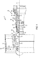
- FIG. 1 schematically illustrates a gas turbine engine 20.
- the gas turbine engine 20 is disclosed herein as a two-spool turbofan that generally incorporates a fan section 22, a compressor section 24, a combustor section 26 and a turbine section 28.
- Alternative engines might include an augmenter section (not shown) among other systems or features.
- the fan section 22 drives air along a bypass flow path B in a bypass duct defined within a nacelle 15, while the compressor section 24 drives air along a primary or core flow path C for compression and communication into the combustor section 26 and then expansion through the turbine section 28.
- the gas turbine engine 20 generally includes a low speed spool 30 and a high speed spool 32 mounted for rotation about an engine central longitudinal axis A relative to an engine static structure 36 via several bearing systems 38. It should be understood that various bearing systems at various locations may alternatively or additionally be provided and the location of the several bearing systems 38 may be varied as appropriate to the application.
- the low speed spool 30 generally includes an inner shaft 40 that interconnects a fan 42, a low pressure compressor 44 and a low pressure turbine 46.
- the inner shaft 40 is connected to the fan 42 through a speed change mechanism, which in this gas turbine engine 20 is illustrated as a fan drive gear system 48 configured to drive the fan 42 at a lower speed than the low speed spool 30.
- the high speed spool 32 includes an outer shaft 50 that interconnects a high pressure compressor 52 and a high pressure turbine 54.
- a combustor 56 is arranged in the gas turbine engine 20 between the high pressure compressor 52 and the high pressure turbine 54.
- a mid-turbine frame 57 of the engine static structure 36 is arranged generally between the high pressure turbine 54 and the low pressure turbine 46 and may include airfoils 59 in the core flow path C for guiding the flow into the low pressure turbine 46.
- the mid-turbine frame 57 further supports the several bearing systems 38 in the turbine section 28.
- the inner shaft 40 and the outer shaft 50 are concentric and rotate via the several bearing systems 38 about the engine central longitudinal axis A, which is collinear with their longitudinal axes.
- each of the positions of the fan section 22, the compressor section 24, the combustor section 26, the turbine section 28, and the fan drive gear system 48 may be varied.
- the fan drive gear system 48 may be located aft of the combustor section 26 or even aft of the turbine section 28, and the fan section 22 may be positioned forward or aft of the fan drive gear system 48.
- the air in the core flow path is compressed by the low pressure compressor 44 and then the high pressure compressor 52, mixed and burned with fuel in the combustor 56, and then expanded over the high pressure turbine 54 and low pressure turbine 46.
- the low pressure turbine 46 and the high pressure turbine 54 rotationally drive the respective low speed spool 30 and the high speed spool 32 in response to the expansion.
- the low speed spool 30 may be engaged with and configured to drive a low spool tower shaft and the high speed spool 32 may be engaged with and configured to be driven by a high spool tower shaft.
- the low spool tower shaft and the high spool tower shaft may be engaged with motors, generators and a differential gear box, collectively configured for power extraction, amplification and redistribution within and among the various components of the gas turbine engine 20.
- a generic compressor map 200 with speed lines 202, operating line 204, stall line 206, and stall margin 208, as shown in FIG. 2 illustrates the compressor stall margin limit in greater detail.
- nominal compressor performance is depicted as a series of lines of constant corrected compressor speed (e.g., the speed lines 202) defining the relationship of compressor pressure ratio as a function of compressor corrected flow at that speed.
- the compressor stall line indicating the upper limit of stall-free operation is depicted as a stall pressure ratio as a function of corrected flow.
- a transient such as produced by rapid acceleration following an increase in fuel flow rate to the combustor, the compressor accelerates from a first rotational speed 210 to a second rotational speed 212 and, under normal conditions (e.g., stall free conditions) follows a transient operating line 214 while accelerating from the first rotational speed 210 to the second rotational speed 212.
- Such transient may occur, for example, during a step climb or a takeoff climb or during an acceleration.
- TSM transient stall margin
- PRstall PRstall
- PR PR is the pressure ratio of the transient operating line 214.
- Stall of the compressor may occur where TSM ⁇ 0 - e.g., where the transient operating line 214 exceeds the stall line 206.
- the gas turbine engine 320 generally includes a low speed spool 330 and a high speed spool 332 mounted for rotation about an engine central longitudinal axis A.
- the low speed spool 330 generally includes an inner shaft 340 that interconnects a fan 342, a low pressure compressor 344 and a low pressure turbine 346.
- the high speed spool 332 includes an outer shaft 350 that interconnects a high pressure compressor 352 and a high pressure turbine 354.
- a combustor 356 is arranged in the gas turbine engine 320 between the high pressure compressor 352 and the high pressure turbine 354.
- the inner shaft 340 and the outer shaft 350 are concentric and rotate via bearing systems about the engine central longitudinal axis A, which is collinear with the longitudinal axes of the inner shaft 340 and the outer shaft 350.
- the gas turbine engine 320 further includes a low spool power assist 360 and a high spool power assist 362.
- the low spool power assist 360 is connected to the low speed spool 330 by a low spool tower shaft 302 and the high spool power assist 362 is connected to the high speed spool 332 by a high spool tower shaft 304.
- the low spool tower shaft 302 includes a low spool bevel gear 310 in meshing engagement with a low spool gear pedestal 312.
- the low spool gear pedestal 312 is coupled to the low speed spool 330, which is similar to the low speed spool 30 described above with reference to FIG. 1 .
- the high spool tower shaft 304 includes a high spool bevel gear 306 in meshing engagement with a high spool gear pedestal 308.
- the high spool gear pedestal 308 is coupled to the high speed spool 332, which is similar to the high speed spool 32 described above with reference to FIG. 1 .
- the high spool gear pedestal 308 and the low spool gear pedestal 312 are mounted on the high speed spool 332 and the low speed spool 330, respectively.
- the low spool power assist 360 is connected directly to the low speed spool 330 by a low spool shaft 361 and the high spool power assist 362 is connected directly to the high speed spool 332 by a high spool shaft 363.
- Such embodiments may be configured, by way of example, as one or more power assist motors positioned in a tail cone and connected to the low speed spool 330 by the low spool shaft 361 to the high speed spool 332 by the high spool shaft 363.
- the low spool power assist 360 and the high spool power assist 362 are electric motors powered by one or more of an auxiliary power unit a storage battery or a capacitor, each of which may be interconnected to provide the required assist to the gas turbine engine during transient operation.
- the low spool power assist 360 and the high spool power assist 362 comprise turbine units configured to operate, for example, by pressurized fluid, such as air, supplied by or bled from an auxiliary power unit.
- the gas turbine engine 320 further includes an inlet pressure sensor 364 and an outlet pressure sensor 365 at the low pressure compressor 344 and an inlet pressure sensor 366 and an outlet pressure sensor 367 at the high pressure compressor 352.
- the gas turbine engine further includes a low spool speed sensor 368 and a high spool speed sensor 369.
- the various sensors provide outputs to a controller which, in various embodiments, is linked to or is part of a full authority digital engine control (“FADEC") 370 that controls operation of the low spool power assist 360 and the high spool power assist 362.
- the various pressure outputs input to the FADEC may be synthesized from related data, including spool speeds and flow rate and temperature data.
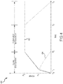
- the power assist schedule 400 comprises an input to a FADEC, such as, for example, the FADEC 370 described above with reference to FIG. 3 , and controls power inputs to a low spool power assist and a high spool power assist, such as, for example, the low spool power assist 360 and the high spool power assist 362 described above with reference to FIG. 3 .
- a transient e.g., an acceleration caused by an increase in fuel flow to the combustor of a gas turbine engine, such as, for example, the gas turbine engine 320 described above with reference to FIG.
- the low spool power assist and the high spool power assist will be operated at different power levels for different periods of time.
- the low spool power assist follows a low spool power assist schedule 402 and the high spool power assist follows a high spool power assist schedule 404.
- the response of the high spool power assist is related to the fuel addition and the operating line control desired for each type of maneuver performed (e.g. takeoff or step climb).
- the response of the low spool power assist is related to the power necessary to maintain a substantially flat high spool response (e.g., a substantially constant rotational speed (N2) of the high spool) after the high spool has accelerated to its quasi-steady state value with low spool assist active. (See, e.g., FIG. 5C ).
- the magnitude of the low spool power assist can also be related to the amount of power assist the engine requires to develop its necessary amount of thrust and the capability of the power electronics.
- both the low spool power assist and the high spool power assist are activated until a first time T1 and first power level P1 are reached.
- first time T1 power to the high spool power assist is phased out during the period of time until a second time T2 is reached, and remains at zero for the duration of the transient.
- power to the low spool power assist increases to a second power level P2.
- the low spool power assist remains at the second power level until a third time T3, following which power to the low spool power assist is gradually phased out until a fourth time T4 is reached.
- power to the low spool power assist remains at power level P2 until altitude is reached, after which the power is gradually phased out.
- the duration of the low spool power assist is related to whether the engine benefits from continued supplemental boost supplied via the low spool power assist.
- One such configuration incorporates a low spool power assist that continues throughout a maneuver, e.g., during a step climb to a higher altitude, beyond the point where transient operation substantially terminates (e.g., out to time T4 in FIG. 4 ).
- This configuration has the potential to reconfigure thermodynamic parameters - e.g., the various Brayton cycle parameters - in order to operate more efficiently at the expense of added weight from batteries or other means of supplying external power to provide the power assist.
- Another such configuration incorporates a low spool power assist during the transient period only, after which the low spool power assist gradually reduces to zero.
- the two-phase approach to power assist provides a first phase (0 ⁇ t ⁇ T2) that controls OpLine management - e.g., management of the transient stall margin to remain within the boundaries of the operating line and the stall line - and a second phase (T2 ⁇ t ⁇ T3 or T4) that controls tip clearance management within the high pressure turbine.
- the boundary between the OpLine management phase and the tip clearance management phase may overlap - e.g., the tip clearance management phase commences before the OpLine management phase terminates.
- FIGS. 5A, 5B and 5C graphs depicting compressor performance, tip clearance and high spool speed (N2), respectively, are provided, during a transient involving a step climb, in accordance with various embodiments.
- a first speed line 510 and a second speed line 512, an operating line 504, a stall line 506, and a stall margin 508 are depicted in similar fashion to the lines described above with reference to FIG. 2 .
- a baseline transient operating line 514 illustrates the behavior of the compressor during a transient, from the first speed line 510 to the second speed line 512 and then back toward the first speed line 510, with no power provided to either the first (or low) spool power assist or to the second (or high) spool power assist.
- the transient stall margin characteristics of the baseline transient operating line 514 are consistent with those described above with reference to FIG. 2 - e.g., the baseline transient operating line approaches the stall line during the transient phase prior to returning to the operating line 504.
- a hybrid transient operating line 515 is also provided, in accordance with the two-phase power assist described above with reference to FIG. 4 . As indicated, during the transient, the hybrid operating line remains substantially on or close to the operating line 504 and, advantageously, maintains a lower transient stall margin ("TSM”) than does the baseline mode of operation.
- TSM transient stall margin
- a baseline tip clearance plot 552 indicates a sudden decrease in clearance of the rotor tips to a minimum value TCB in the high pressure turbine following initiation of the transient at T0, followed by a slow relaxation of the tip clearance back to a steady state value.
- the reduction in tip clearance corresponds with the rapid increase in rotational speed of the high pressure turbine following the increase in the rate of fuel flow, thereby suggesting a benefit in reducing the speed of the high speed spool as quickly as possible following the initial transient.
- a hybrid tip clearance plot 554 also indicates a sudden decrease in clearance of the rotor tips to a minimum value TCH in the high pressure turbine following initiation of the transient at T0, followed by a slow relaxation of the tip clearance back to a steady state value.
- the minimum value of tip clearance TCH may be substantially greater than the minimum value of tip clearance TCB for the baseline case, leading to a more desirable transient operating condition.
- a graph 560 depicts rotational speed (N2) of the high speed spool above a nominal operating speed N20 prior to initiation of the transient at T0.
- a baseline rotational speed plot 562 indicates a rapid rise in rotational speed to a maximum value N2B, following initiation of the transient at T0, followed by a slight relaxation in speed to a steady state value.
- a hybrid rotational speed plot 564 indicates a rapid rise in rotational speed to a maximum value N2H, which is also near its steady state value.
- the maximum value of the hybrid case (N2H) is substantially less than the maximum value of the baseline case (N2B) as is the situation for both steady state values.
- the lower value of rotational speed for the hybrid case (N2H) is believed to correspond with and lead to the more favorable value of tip clearance described above and depicted in the hybrid tip clearance plot 554.
- FIGS. 4 and 5A, 5B and 5C further beneficial aspects of the two-phase application of power to the low spool power assist and to the high spool power assist may be seen.
- Applying power to both the low spool power assist and to the high spool power assist during the first phase of the transient - e.g., from T0 to T2 - increases the rotational speed of the high speed spool.
- Phasing out the high spool power assist at T2 then allows the high speed spool to maintain a constant speed (N2H) throughout the transient following the initial acceleration from N0.
- N2H constant speed
- Continued operation of the low spool power assist - e.g., from T2 to T3 or T4 - enables the high speed spool to operate at a lower rotational speed than might otherwise be required during the transient, thereby maintaining an acceptable tip clearance in the high pressure turbine between the rotor tips and the turbine casing.
- a control diagram 600 for operation of a controller is provided, illustrating sensor inputs and the flow of data obtained from the sensor inputs to schedule the high spool and low spool power assists, in accordance with various embodiments.
- the control diagram 600 provides for an electronic engine controller 602 (or controller).
- Inputs to the electronic engine controller 602 include altitude and Mach number data, obtained from an altitude and Mach number sensor(s) 604 ("Alt, MN"); throttle level sensing, obtained from a throttle lever angle sensor 606 ("TLA Request”); low spool speed data, obtained from a low spool speed sensor 608 ("N1"); temperature data, obtained from a temperature sensor 610 ("T2") positioned proximate an inlet to the low pressure compressor; low pressure compressor outlet relief bleed data, obtained from a feedback sensor 612 (“B25 POS”) configured to provide feedback data relative to the operational status of a bleed valve positioned proximate the exit of the low pressure compressor; tip clearance control data, obtained from an active clearance control sensor 614 (“ACC POS”) and high spool speed data, obtained from a high spool speed sensor 616 (“N2").
- Alt, MN altitude and Mach number sensor(s) 604
- TLA Request throttle lever angle sensor 606
- N1 low spool speed data
- the electronic engine controller 602 determines a low spool speed setting 618 (“N1CSET”) based on the throttle lever angle sensor 606 and a corrected low spool speed value 620 (“N1C2”), based on the corrected mass flow proximate the inlet of the low pressure compressor.
- N1CSET low spool speed setting 618
- N1C2 corrected low spool speed value 620
- the difference between N1CSET and N1C2 may be used to adjust the level of power assist applied to one or both of the low speed spool and the high speed spool.
- a temperature value 622 (“T25SYN”) proximate the outlet of the low pressure compressor may be synthesized based on the corrected low speed spool value 620, the feedback sensor 612 ("B25 POS"), and the tip clearance control data, obtained from the active clearance control sensor 614 ("ACC POS").
- active clearance control may be affected by spraying cooling fluid - e.g., compressed air bled from a compressor stage - about the outer surface of the engine casing, causing the engine casing to contract in a radial direction.
- the clearance control sensor may operate indirectly by measuring the temperature of the engine casing and the temperature of the gas within the turbine or directly by measuring the actual tip clearance between the blade tips and the inner surface of the engine casing.
- a corrected high spool speed value 624 (“N2C25") is determined using the temperature value 622 (“T25SYN”) and the high spool speed data, obtained from the high spool speed sensor 616 ("N2").
- the data representing the corrected high spool speed value 624 (“N2C25”), the tip clearance control data, obtained from the active clearance control sensor 614 ("ACC POS") and the high spool speed data, obtained from the high spool speed sensor 616 (“N2”) may be used to adjust the level of power assist applied to either or both of the low speed spool and the high speed spool.
- the levels of low and high power assist determined by the electronic engine controller 602 are finally provided by a low and high assist command module 626 and then provided as a low spool command 628 and a high spool command 630 to the mechanisms - e.g., the electric motor(s) used to provide auxiliary power to a low spool power assist and a high spool power assist as described above.
- references to "one embodiment”, “an embodiment”, “various embodiments”, etc. indicate that the embodiment described may include a particular feature, structure, or characteristic, but every embodiment may not necessarily include the particular feature, structure, or characteristic. Moreover, such phrases are not necessarily referring to the same embodiment. Further, when a particular feature, structure, or characteristic is described in connection with an embodiment, it is submitted that it is within the knowledge of one skilled in the art to affect such feature, structure, or characteristic in connection with other embodiments whether or not explicitly described. After reading the description, it will be apparent to one skilled in the relevant art(s) how to implement the disclosure in alternative embodiments.
Landscapes
- Engineering & Computer Science (AREA)
- Mechanical Engineering (AREA)
- General Engineering & Computer Science (AREA)
- Chemical & Material Sciences (AREA)
- Combustion & Propulsion (AREA)
- Control Of Positive-Displacement Air Blowers (AREA)
Abstract
Description
- The present disclosure relates generally to gas turbine engines and, more particularly, methods and apparatus used to control stability and turbine rotor blade clearance in gas turbine engines during transient operation.
- A gas turbine engine typically includes a fan section, a compressor section, a combustor section and a turbine section. Air entering the compressor section is compressed and delivered into the combustion section, where it is mixed with fuel and ignited to generate a high-speed exhaust gas flow. The high-energy exhaust gas flow expands through the turbine section to drive the compressor and the fan section. The compressor section typically includes low and high pressure compressors, and the turbine section includes low and high pressure turbines. The high pressure turbine drives the high pressure compressor through an outer shaft to form a high spool, and the low pressure turbine drives the low pressure compressor through an inner shaft to form a low spool. The fan section may also be driven by the low spool inner shaft, either directly or indirectly through a fan drive gear system.
- Over the course of an operating cycle of a gas turbine engine, the compressor section may experience compressor stall. Compressor stall is a limiting factor in the operation of gas turbine engines. For example, an unstable flow may develop in the compressor section during acceleration. Such unstable flow may lead to stall, which may increase turbine temperature and mechanical vibration and decrease rotor tip clearance. During transient engine operation (e.g., during engine acceleration), the compressor operating line may shift significantly with respect to steady-state conditions. For example, the flow exiting the compressor as a function of pressure may be significantly reduced as fuel flow is increased during an engine acceleration transient, thereby substantially changing the compressor operating line. Methods and apparatus tending to reduce the onset of stall during transient operation are therefore desirable.
- A method of maintaining rotor tip clearance during a transient operation of a gas turbine engine is disclosed. In various embodiments, the method includes applying auxiliary high spool power to a high speed spool for a first time period, applying low spool auxiliary power to a low speed spool for a second time period, sensing one or more operational parameters of the gas turbine engine during the transient operation, and ceasing application of power to the high speed spool, based on the one or more operational parameters.
- In various embodiments, the applying high spool auxiliary power to the high speed spool comprises driving a high spool shaft connected to the high speed spool. In various embodiments, the applying low spool auxiliary power to the low speed spool comprises driving a low spool shaft connected to the low speed spool. In various embodiments, the driving the high spool shaft comprises powering a high spool tower-shaft via an electric motor. In various embodiments, the driving the low spool shaft comprises powering a low spool tower-shaft via an electric motor.
- In various embodiments, the one or more operational parameters includes a high speed spool rotational speed and a low speed spool rotational speed. In various embodiments, the one or more operational parameters includes a high pressure compressor pressure ratio and a low pressure compressor pressure ratio.
- In various embodiments, the transient operation is a step climb, the applying the high spool auxiliary power to the high speed spool for the first time period and the applying the low spool auxiliary power to the low speed spool for the second time period are configured to commence simultaneously and the applying high spool auxiliary power to a high speed spool ceases following the first time period. In various embodiments, the applying low spool auxiliary power to the low speed spool continues until expiration of the step climb. In various embodiments, a rotational speed of the high speed spool remains constant following the first time period.
- A system for maintaining acceptable rotor tip clearance during a transient operation of a gas turbine engine is disclosed. In various embodiments, the system includes a high speed spool connecting a high pressure compressor to a high pressure turbine, a low speed spool connecting a low pressure compressor to a low pressure turbine, a high speed spool auxiliary power input configured to provide power for a first time period during the transient operation, a low speed spool auxiliary power input configured to provide power for a second time period during the transient operation, and a controller configured to monitor performance of the gas turbine engine during the transient operation and to cease power to the high speed auxiliary power input based on one or more sensed parameters.
- In various embodiments, the high speed spool auxiliary power input comprises a high spool tower shaft connected to the high speed spool. In various embodiments, the low speed spool auxiliary power input comprises a low spool tower shaft connected to the low speed spool. In various embodiments, a high spool tower shaft electric motor is connected to the high spool tower shaft. In various embodiments, a low spool tower shaft electric motor connected to the low spool tower shaft.
- In various embodiments, a high speed spool rotational speed sensor and a low speed spool rotational speed sensor are configured to provide the one or more sensed parameters to the full authority digital engine control. In various embodiments, a high pressure inlet pressure sensor and a high pressure outlet pressure sensor at the high pressure compressor are configured to provide the one or more sensed parameters to the controller. In various embodiments, a low pressure inlet pressure sensor and a low pressure outlet pressure sensor at the low pressure compressor are configured to provide the one or more sensed parameters to the controller.
- In various embodiments, the transient operation is a step climb and the controller is configured to cease power to the high speed spool auxiliary power input following the first time period. In various embodiments, a rotational speed of the high speed spool remains constant following the first time period.
- The subject matter of the present disclosure is particularly pointed out and distinctly claimed in the concluding portion of the specification. A more complete understanding of the present disclosure, however, may best be obtained by referring to the following detailed description and claims in connection with the following drawings. While the drawings illustrate various embodiments employing the principles described herein, the drawings do not limit the scope of the claims.
-
FIG. 1 is a cross sectional schematic view of a gas turbine engine, in accordance with various embodiments; -
FIG. 2 is a graph illustrating a compressor map and transient behavior of a compressor, in accordance with various embodiments; -
FIG. 3 is a schematic diagram of a gas turbine engine, in accordance with various embodiments; -
FIG. 4 is a graph illustrating a power input schedule to high and low spools of a gas turbine engine, in accordance with various embodiments; -
FIGS. 5A, 5B and 5C are graphs showing compressor performance, turbine rotor tip clearance and high speed spool rotational speed, in accordance with various embodiments; and -
FIG. 6 is a control diagram, illustrating sensor inputs and power assist outputs, in accordance with various embodiments. - The following detailed description of various embodiments herein makes reference to the accompanying drawings, which show various embodiments by way of illustration. While these various embodiments are described in sufficient detail to enable those skilled in the art to practice the disclosure, it should be understood that other embodiments may be realized and that changes may be made without departing from the scope of the disclosure. Thus, the detailed description herein is presented for purposes of illustration only and not of limitation. Furthermore, any reference to singular includes plural embodiments, and any reference to more than one component or step may include a singular embodiment or step. Also, any reference to attached, fixed, connected, or the like may include permanent, removable, temporary, partial, full or any other possible attachment option. Additionally, any reference to without contact (or similar phrases) may also include reduced contact or minimal contact. It should also be understood that unless specifically stated otherwise, references to "a," "an" or "the" may include one or more than one and that reference to an item in the singular may also include the item in the plural. Further, all ranges may include upper and lower values and all ranges and ratio limits disclosed herein may be combined.
- Referring now to the drawings,
FIG. 1 schematically illustrates agas turbine engine 20. Thegas turbine engine 20 is disclosed herein as a two-spool turbofan that generally incorporates afan section 22, acompressor section 24, acombustor section 26 and aturbine section 28. Alternative engines might include an augmenter section (not shown) among other systems or features. Thefan section 22 drives air along a bypass flow path B in a bypass duct defined within anacelle 15, while thecompressor section 24 drives air along a primary or core flow path C for compression and communication into thecombustor section 26 and then expansion through theturbine section 28. Although depicted as a two-spool turbofan gas turbine engine in the disclosed non-limiting embodiment, it will be understood that the concepts described herein are not limited to use with two-spool turbofans as the teachings may be applied to other types of turbine engines, including three-spool architectures. - The
gas turbine engine 20 generally includes alow speed spool 30 and ahigh speed spool 32 mounted for rotation about an engine central longitudinal axis A relative to an enginestatic structure 36 viaseveral bearing systems 38. It should be understood that various bearing systems at various locations may alternatively or additionally be provided and the location of theseveral bearing systems 38 may be varied as appropriate to the application. Thelow speed spool 30 generally includes aninner shaft 40 that interconnects afan 42, alow pressure compressor 44 and alow pressure turbine 46. Theinner shaft 40 is connected to thefan 42 through a speed change mechanism, which in thisgas turbine engine 20 is illustrated as a fan drive gear system 48 configured to drive thefan 42 at a lower speed than thelow speed spool 30. Thehigh speed spool 32 includes anouter shaft 50 that interconnects ahigh pressure compressor 52 and ahigh pressure turbine 54. - A
combustor 56 is arranged in thegas turbine engine 20 between thehigh pressure compressor 52 and thehigh pressure turbine 54. Amid-turbine frame 57 of the enginestatic structure 36 is arranged generally between thehigh pressure turbine 54 and thelow pressure turbine 46 and may includeairfoils 59 in the core flow path C for guiding the flow into thelow pressure turbine 46. Themid-turbine frame 57 further supports theseveral bearing systems 38 in theturbine section 28. Theinner shaft 40 and theouter shaft 50 are concentric and rotate via theseveral bearing systems 38 about the engine central longitudinal axis A, which is collinear with their longitudinal axes. It will be appreciated that each of the positions of thefan section 22, thecompressor section 24, thecombustor section 26, theturbine section 28, and the fan drive gear system 48 may be varied. For example, the fan drive gear system 48 may be located aft of thecombustor section 26 or even aft of theturbine section 28, and thefan section 22 may be positioned forward or aft of the fan drive gear system 48. - During operation of the
gas turbine engine 20, the air in the core flow path is compressed by thelow pressure compressor 44 and then thehigh pressure compressor 52, mixed and burned with fuel in thecombustor 56, and then expanded over thehigh pressure turbine 54 andlow pressure turbine 46. Thelow pressure turbine 46 and thehigh pressure turbine 54 rotationally drive the respectivelow speed spool 30 and thehigh speed spool 32 in response to the expansion. As will be described in further detail below, thelow speed spool 30 may be engaged with and configured to drive a low spool tower shaft and thehigh speed spool 32 may be engaged with and configured to be driven by a high spool tower shaft. The low spool tower shaft and the high spool tower shaft may be engaged with motors, generators and a differential gear box, collectively configured for power extraction, amplification and redistribution within and among the various components of thegas turbine engine 20. - The operation and performance of the
gas turbine engine 20 during transient operation may be affected by aerodynamic stall associated with thecompressor section 24. This condition typically results from excessive compressor airfoil loading, resulting in flow separation from the suction sides of one or more airfoils within thecompressor section 24. Significant degradation of compressor and engine performance may result from such aerodynamic stall. Ageneric compressor map 200 withspeed lines 202, operatingline 204,stall line 206, and stallmargin 208, as shown inFIG. 2 , illustrates the compressor stall margin limit in greater detail. In this figure, nominal compressor performance is depicted as a series of lines of constant corrected compressor speed (e.g., the speed lines 202) defining the relationship of compressor pressure ratio as a function of compressor corrected flow at that speed. Furthermore, the compressor stall line indicating the upper limit of stall-free operation is depicted as a stall pressure ratio as a function of corrected flow. During a transient, such as produced by rapid acceleration following an increase in fuel flow rate to the combustor, the compressor accelerates from a firstrotational speed 210 to a secondrotational speed 212 and, under normal conditions (e.g., stall free conditions) follows atransient operating line 214 while accelerating from the firstrotational speed 210 to the secondrotational speed 212. Such transient may occur, for example, during a step climb or a takeoff climb or during an acceleration. As illustrated, during the transient, thestall margin 208 typical of steady state operation (or very slow acceleration) is reduced to atransient stall margin 216. The transient stall margin ("TSM") may be expressed as TSM = (PRstall - PR)/PR ∗ 100, where PRstall is the pressure ratio at thestall line 206 and PR is the pressure ratio of thetransient operating line 214. Stall of the compressor may occur where TSM ≤ 0 - e.g., where thetransient operating line 214 exceeds thestall line 206. - Referring now to
FIG. 3 , a schematic illustration of agas turbine engine 320 is provided. Similar to the description above with reference toFIG. 1 , thegas turbine engine 320 generally includes alow speed spool 330 and ahigh speed spool 332 mounted for rotation about an engine central longitudinal axis A. Thelow speed spool 330 generally includes aninner shaft 340 that interconnects afan 342, alow pressure compressor 344 and alow pressure turbine 346. Thehigh speed spool 332 includes anouter shaft 350 that interconnects ahigh pressure compressor 352 and ahigh pressure turbine 354. Acombustor 356 is arranged in thegas turbine engine 320 between thehigh pressure compressor 352 and thehigh pressure turbine 354. Theinner shaft 340 and theouter shaft 350 are concentric and rotate via bearing systems about the engine central longitudinal axis A, which is collinear with the longitudinal axes of theinner shaft 340 and theouter shaft 350. - The
gas turbine engine 320 further includes a lowspool power assist 360 and a highspool power assist 362. In various embodiments, the lowspool power assist 360 is connected to thelow speed spool 330 by a lowspool tower shaft 302 and the highspool power assist 362 is connected to thehigh speed spool 332 by a highspool tower shaft 304. In various embodiments, the lowspool tower shaft 302 includes a lowspool bevel gear 310 in meshing engagement with a lowspool gear pedestal 312. The lowspool gear pedestal 312 is coupled to thelow speed spool 330, which is similar to thelow speed spool 30 described above with reference toFIG. 1 . Similarly, the highspool tower shaft 304 includes a highspool bevel gear 306 in meshing engagement with a highspool gear pedestal 308. The highspool gear pedestal 308 is coupled to thehigh speed spool 332, which is similar to thehigh speed spool 32 described above with reference toFIG. 1 . In various embodiments, the highspool gear pedestal 308 and the lowspool gear pedestal 312 are mounted on thehigh speed spool 332 and thelow speed spool 330, respectively. - In various embodiments, the low
spool power assist 360 is connected directly to thelow speed spool 330 by alow spool shaft 361 and the highspool power assist 362 is connected directly to thehigh speed spool 332 by ahigh spool shaft 363. Such embodiments may be configured, by way of example, as one or more power assist motors positioned in a tail cone and connected to thelow speed spool 330 by thelow spool shaft 361 to thehigh speed spool 332 by thehigh spool shaft 363. In various embodiments, the lowspool power assist 360 and the highspool power assist 362 are electric motors powered by one or more of an auxiliary power unit a storage battery or a capacitor, each of which may be interconnected to provide the required assist to the gas turbine engine during transient operation. In various embodiments, the lowspool power assist 360 and the highspool power assist 362 comprise turbine units configured to operate, for example, by pressurized fluid, such as air, supplied by or bled from an auxiliary power unit. - In various embodiments, the
gas turbine engine 320 further includes aninlet pressure sensor 364 and anoutlet pressure sensor 365 at thelow pressure compressor 344 and aninlet pressure sensor 366 and anoutlet pressure sensor 367 at thehigh pressure compressor 352. In various embodiments, the gas turbine engine further includes a lowspool speed sensor 368 and a highspool speed sensor 369. During a transient operation, the various sensors provide outputs to a controller which, in various embodiments, is linked to or is part of a full authority digital engine control ("FADEC") 370 that controls operation of the lowspool power assist 360 and the highspool power assist 362. In various embodiments, the various pressure outputs input to the FADEC may be synthesized from related data, including spool speeds and flow rate and temperature data. - Referring now to
FIG. 4 , apower assist schedule 400 is illustrated, in accordance with various embodiments. In various embodiments, thepower assist schedule 400 comprises an input to a FADEC, such as, for example, theFADEC 370 described above with reference toFIG. 3 , and controls power inputs to a low spool power assist and a high spool power assist, such as, for example, the lowspool power assist 360 and the high spool power assist 362 described above with reference toFIG. 3 . In various embodiments, during a transient - e.g., an acceleration caused by an increase in fuel flow to the combustor of a gas turbine engine, such as, for example, thegas turbine engine 320 described above with reference toFIG. 3 - the low spool power assist and the high spool power assist will be operated at different power levels for different periods of time. For example, during such transient, the low spool power assist follows a low spoolpower assist schedule 402 and the high spool power assist follows a high spoolpower assist schedule 404. The response of the high spool power assist is related to the fuel addition and the operating line control desired for each type of maneuver performed (e.g. takeoff or step climb). The response of the low spool power assist is related to the power necessary to maintain a substantially flat high spool response (e.g., a substantially constant rotational speed (N2) of the high spool) after the high spool has accelerated to its quasi-steady state value with low spool assist active. (See, e.g.,FIG. 5C ). The magnitude of the low spool power assist can also be related to the amount of power assist the engine requires to develop its necessary amount of thrust and the capability of the power electronics. - By way of non-limiting example, in various embodiments, following commencement of the transient - e.g., following an increase in the rate of fuel flow to the combustor initiated by movement of the throttle - both the low spool power assist and the high spool power assist are activated until a first time T1 and first power level P1 are reached. Following the first time T1, power to the high spool power assist is phased out during the period of time until a second time T2 is reached, and remains at zero for the duration of the transient. During this same period of time, power to the low spool power assist increases to a second power level P2. During, for example, a transient not involving a change in altitude, the low spool power assist remains at the second power level until a third time T3, following which power to the low spool power assist is gradually phased out until a fourth time T4 is reached. During other transients, such as, for example, those accompanying a step climb or a takeoff climb, power to the low spool power assist remains at power level P2 until altitude is reached, after which the power is gradually phased out. In various embodiments, the duration of the low spool power assist is related to whether the engine benefits from continued supplemental boost supplied via the low spool power assist. One such configuration incorporates a low spool power assist that continues throughout a maneuver, e.g., during a step climb to a higher altitude, beyond the point where transient operation substantially terminates (e.g., out to time T4 in
FIG. 4 ). This configuration has the potential to reconfigure thermodynamic parameters - e.g., the various Brayton cycle parameters - in order to operate more efficiently at the expense of added weight from batteries or other means of supplying external power to provide the power assist. Another such configuration incorporates a low spool power assist during the transient period only, after which the low spool power assist gradually reduces to zero. As will be discussed further below, the two-phase approach to power assist provides a first phase (0 ≤ t ≤ T2) that controls OpLine management - e.g., management of the transient stall margin to remain within the boundaries of the operating line and the stall line - and a second phase (T2 ≤ t ≤ T3 or T4) that controls tip clearance management within the high pressure turbine. In various embodiments, however, the boundary between the OpLine management phase and the tip clearance management phase may overlap - e.g., the tip clearance management phase commences before the OpLine management phase terminates. - Referring now to
FIGS. 5A, 5B and 5C , graphs depicting compressor performance, tip clearance and high spool speed (N2), respectively, are provided, during a transient involving a step climb, in accordance with various embodiments. Referring to the graph ofcompressor performance 500, afirst speed line 510 and asecond speed line 512, anoperating line 504, astall line 506, and astall margin 508 are depicted in similar fashion to the lines described above with reference toFIG. 2 . A baselinetransient operating line 514 illustrates the behavior of the compressor during a transient, from thefirst speed line 510 to thesecond speed line 512 and then back toward thefirst speed line 510, with no power provided to either the first (or low) spool power assist or to the second (or high) spool power assist. The transient stall margin characteristics of the baselinetransient operating line 514 are consistent with those described above with reference toFIG. 2 - e.g., the baseline transient operating line approaches the stall line during the transient phase prior to returning to theoperating line 504. A hybridtransient operating line 515 is also provided, in accordance with the two-phase power assist described above with reference toFIG. 4 . As indicated, during the transient, the hybrid operating line remains substantially on or close to theoperating line 504 and, advantageously, maintains a lower transient stall margin ("TSM") than does the baseline mode of operation. - Referring now to the graph depicting
tip clearance 550 inFIG. 5B , a baselinetip clearance plot 552 indicates a sudden decrease in clearance of the rotor tips to a minimum value TCB in the high pressure turbine following initiation of the transient at T0, followed by a slow relaxation of the tip clearance back to a steady state value. In various embodiments, the reduction in tip clearance corresponds with the rapid increase in rotational speed of the high pressure turbine following the increase in the rate of fuel flow, thereby suggesting a benefit in reducing the speed of the high speed spool as quickly as possible following the initial transient. Referring still to the same graph, a hybridtip clearance plot 554 also indicates a sudden decrease in clearance of the rotor tips to a minimum value TCH in the high pressure turbine following initiation of the transient at T0, followed by a slow relaxation of the tip clearance back to a steady state value. However, in the hybrid case, the minimum value of tip clearance TCH may be substantially greater than the minimum value of tip clearance TCB for the baseline case, leading to a more desirable transient operating condition. - Referring now to
FIG. 5C , agraph 560 depicts rotational speed (N2) of the high speed spool above a nominal operating speed N20 prior to initiation of the transient at T0. A baselinerotational speed plot 562 indicates a rapid rise in rotational speed to a maximum value N2B, following initiation of the transient at T0, followed by a slight relaxation in speed to a steady state value. Referring to the same graph, a hybridrotational speed plot 564 indicates a rapid rise in rotational speed to a maximum value N2H, which is also near its steady state value. Advantageously, the maximum value of the hybrid case (N2H) is substantially less than the maximum value of the baseline case (N2B) as is the situation for both steady state values. The lower value of rotational speed for the hybrid case (N2H) is believed to correspond with and lead to the more favorable value of tip clearance described above and depicted in the hybridtip clearance plot 554. - Referring now to
FIGS. 4 and5A, 5B and 5C , further beneficial aspects of the two-phase application of power to the low spool power assist and to the high spool power assist may be seen. Applying power to both the low spool power assist and to the high spool power assist during the first phase of the transient - e.g., from T0 to T2 - increases the rotational speed of the high speed spool. The increased speed of the high speed spool is desirable for OpLine management, such that the transient stall margin may be kept as within a desirable margin - e.g., TSM = 10-20% - during the transient. Phasing out the high spool power assist at T2 then allows the high speed spool to maintain a constant speed (N2H) throughout the transient following the initial acceleration from N0. Continued operation of the low spool power assist - e.g., from T2 to T3 or T4 - enables the high speed spool to operate at a lower rotational speed than might otherwise be required during the transient, thereby maintaining an acceptable tip clearance in the high pressure turbine between the rotor tips and the turbine casing. - Referring now to
FIG. 6 , a control diagram 600 for operation of a controller is provided, illustrating sensor inputs and the flow of data obtained from the sensor inputs to schedule the high spool and low spool power assists, in accordance with various embodiments. In various embodiments, the control diagram 600 provides for an electronic engine controller 602 (or controller). Inputs to theelectronic engine controller 602 include altitude and Mach number data, obtained from an altitude and Mach number sensor(s) 604 ("Alt, MN"); throttle level sensing, obtained from a throttle lever angle sensor 606 ("TLA Request"); low spool speed data, obtained from a low spool speed sensor 608 ("N1"); temperature data, obtained from a temperature sensor 610 ("T2") positioned proximate an inlet to the low pressure compressor; low pressure compressor outlet relief bleed data, obtained from a feedback sensor 612 ("B25 POS") configured to provide feedback data relative to the operational status of a bleed valve positioned proximate the exit of the low pressure compressor; tip clearance control data, obtained from an active clearance control sensor 614 ("ACC POS") and high spool speed data, obtained from a high spool speed sensor 616 ("N2"). - In various embodiments, the
electronic engine controller 602 determines a low spool speed setting 618 ("N1CSET") based on the throttlelever angle sensor 606 and a corrected low spool speed value 620 ("N1C2"), based on the corrected mass flow proximate the inlet of the low pressure compressor. In various embodiments, the difference between N1CSET and N1C2 may be used to adjust the level of power assist applied to one or both of the low speed spool and the high speed spool. In various embodiments, a temperature value 622 ("T25SYN") proximate the outlet of the low pressure compressor may be synthesized based on the corrected lowspeed spool value 620, the feedback sensor 612 ("B25 POS"), and the tip clearance control data, obtained from the active clearance control sensor 614 ("ACC POS"). In various embodiments, active clearance control may be affected by spraying cooling fluid - e.g., compressed air bled from a compressor stage - about the outer surface of the engine casing, causing the engine casing to contract in a radial direction. Further, in various embodiments, the clearance control sensor may operate indirectly by measuring the temperature of the engine casing and the temperature of the gas within the turbine or directly by measuring the actual tip clearance between the blade tips and the inner surface of the engine casing. In various embodiments, a corrected high spool speed value 624 ("N2C25") is determined using the temperature value 622 ("T25SYN") and the high spool speed data, obtained from the high spool speed sensor 616 ("N2"). In various embodiments, the data representing the corrected high spool speed value 624 ("N2C25"), the tip clearance control data, obtained from the active clearance control sensor 614 ("ACC POS") and the high spool speed data, obtained from the high spool speed sensor 616 ("N2") may be used to adjust the level of power assist applied to either or both of the low speed spool and the high speed spool. In various embodiments, the levels of low and high power assist determined by theelectronic engine controller 602 are finally provided by a low and highassist command module 626 and then provided as alow spool command 628 and ahigh spool command 630 to the mechanisms - e.g., the electric motor(s) used to provide auxiliary power to a low spool power assist and a high spool power assist as described above. - Finally, it should be understood that any of the above described concepts can be used alone or in combination with any or all of the other above described concepts. Although various embodiments have been disclosed and described, one of ordinary skill in this art would recognize that certain modifications would come within the scope of this disclosure. Accordingly, the description is not intended to be exhaustive or to limit the principles described or illustrated herein to any precise form. Many modifications and variations are possible in light of the above teaching.
- Benefits, other advantages, and solutions to problems have been described herein with regard to specific embodiments. Furthermore, the connecting lines shown in the various figures contained herein are intended to represent exemplary functional relationships and/or physical couplings between the various elements. It should be noted that many alternative or additional functional relationships or physical connections may be present in a practical system. However, the benefits, advantages, solutions to problems, and any elements that may cause any benefit, advantage, or solution to occur or become more pronounced are not to be construed as critical, required, or essential features or elements of the disclosure. The scope of the disclosure is accordingly to be limited by nothing other than the appended claims, in which reference to an element in the singular is not intended to mean "one and only one" unless explicitly so stated, but rather "one or more." Moreover, where a phrase similar to "at least one of A, B, or C" is used in the claims, it is intended that the phrase be interpreted to mean that A alone may be present in an embodiment, B alone may be present in an embodiment, C alone may be present in an embodiment, or that any combination of the elements A, B and C may be present in a single embodiment; for example, A and B, A and C, B and C, or A and B and C. Different cross-hatching is used throughout the figures to denote different parts but not necessarily to denote the same or different materials.
- Systems, methods and apparatus are provided herein. In the detailed description herein, references to "one embodiment", "an embodiment", "various embodiments", etc., indicate that the embodiment described may include a particular feature, structure, or characteristic, but every embodiment may not necessarily include the particular feature, structure, or characteristic. Moreover, such phrases are not necessarily referring to the same embodiment. Further, when a particular feature, structure, or characteristic is described in connection with an embodiment, it is submitted that it is within the knowledge of one skilled in the art to affect such feature, structure, or characteristic in connection with other embodiments whether or not explicitly described. After reading the description, it will be apparent to one skilled in the relevant art(s) how to implement the disclosure in alternative embodiments.
- Furthermore, no element, component, or method step in the present disclosure is intended to be dedicated to the public regardless of whether the element, component, or method step is explicitly recited in the claims. No claim element herein is to be construed under the provisions of 35 U.S.C. 112(f) unless the element is expressly recited using the phrase "means for." As used herein, the terms "comprises", "comprising", or any other variation thereof, are intended to cover a non-exclusive inclusion, such that a process, method, article, or apparatus that comprises a list of elements does not include only those elements but may include other elements not expressly listed or inherent to such process, method, article, or apparatus.
Claims (15)
- A method of maintaining rotor tip clearance during a transient operation of a gas turbine engine, comprising:applying high spool auxiliary power to a high speed spool for a first time period;applying low spool auxiliary power to a low speed spool for a second time period;sensing one or more operational parameters of the gas turbine engine during the transient operation; andceasing application of power to the high speed spool, based on the one or more operational parameters.
- The method of claim 1, wherein the applying the high spool auxiliary power to the high speed spool comprises driving a high spool shaft connected to the high speed spool.
- The method of claim 1 or 2, wherein the applying the low spool auxiliary power to the low speed spool comprises driving a low spool shaft connected to the low speed spool.
- The method of claim 2 or 3, wherein the driving the high spool shaft comprises powering a high spool tower-shaft via an electric motor.
- The method of claim 3 or 4, wherein the driving the low spool shaft comprises powering a low spool tower-shaft via an electric motor.
- The method of any preceding claim, wherein the one or more operational parameters includes a high speed spool rotational speed and a low speed spool rotational speed.
- The method of claim 6, wherein the one or more operational parameters includes a high pressure compressor pressure ratio and a low pressure compressor pressure ratio.
- The method of any preceding claim, wherein the transient operation is a step climb, wherein the applying the high spool auxiliary power to the high speed spool for the first time period and the applying the low spool auxiliary power to the low speed spool for the second time period is configured to commence simultaneously and wherein the applying the high spool auxiliary power to a high speed spool ceases following the first time period.
- The method of claim 8, wherein the applying the low spool auxiliary power to the low speed spool continues until expiration of the step climb,
wherein, optionally, a rotational speed of the high speed spool remains constant following the first time period. - A system for maintaining rotor tip clearance during a transient operation of a gas turbine engine, comprising:a high speed spool connecting a high pressure compressor to a high pressure turbine;a low speed spool connecting a low pressure compressor to a low pressure turbine;a high speed spool auxiliary power input configured to provide high spool power for a first time period during the transient operation;a low speed spool auxiliary power input configured to provide low spool power for a second time period during the transient operation; anda controller configured to monitor performance of the gas turbine engine during the transient operation and to cease the high spool power to the high speed auxiliary power input based on one or more sensed parameters.
- The system of claim 10, wherein the high speed spool auxiliary power input comprises a high spool tower shaft connected to the high speed spool.
- The system of claim 11, wherein the low speed spool auxiliary power input comprises a low spool tower shaft connected to the low speed spool.
- The system of claim 12, further comprising a high spool tower shaft electric motor connected to the high spool tower shaft.
- The system of claim 13, further comprising a low spool tower shaft electric motor connected to the low spool tower shaft.
- The system of claim 14, further comprising a high speed spool rotational speed sensor and a low speed spool rotational speed sensor configured to provide the one or more sensed parameters to the full authority digital engine control,
optionally further comprising a high pressure inlet pressure sensor and a high pressure outlet pressure sensor at the high pressure compressor configured to provide the one or more sensed parameters to the controller,
optionally further comprising a low pressure inlet pressure sensor and a low pressure outlet pressure sensor at the low pressure compressor configured to provide the one or more sensed parameters to the controller,
wherein, optionally, the transient operation is a step climb and the controller is configured to cease power to the high speed spool auxiliary power input, following the first time period,
wherein, optionally, at least one of a high pressure compressor pressure ratio and a low pressure compressor pressure ratio is synthesized from the one or more sensed parameters by the controller.
Applications Claiming Priority (1)
| Application Number | Priority Date | Filing Date | Title |
|---|---|---|---|
| US16/039,929 US10934972B2 (en) | 2018-07-19 | 2018-07-19 | Stability margin and clearance control using power extraction and assist of a gas turbine engine |
Publications (2)
| Publication Number | Publication Date |
|---|---|
| EP3597873A1 true EP3597873A1 (en) | 2020-01-22 |
| EP3597873B1 EP3597873B1 (en) | 2021-06-16 |
Family
ID=67437993
Family Applications (1)
| Application Number | Title | Priority Date | Filing Date |
|---|---|---|---|
| EP19187008.8A Active EP3597873B1 (en) | 2018-07-19 | 2019-07-18 | Stability margin and clearance control using power extraction and assist of a gas turbine engine |
Country Status (2)
| Country | Link |
|---|---|
| US (1) | US10934972B2 (en) |
| EP (1) | EP3597873B1 (en) |
Families Citing this family (19)
| Publication number | Priority date | Publication date | Assignee | Title |
|---|---|---|---|---|
| FR3093769B1 (en) * | 2019-03-15 | 2021-04-02 | Safran Aircraft Engines | Method of regulating the temperature of the exhaust gases of a turbomachine |
| GB2584696A (en) * | 2019-06-12 | 2020-12-16 | Rolls Royce Plc | Generating electrical power at high thrust conditions |
| GB2584693A (en) * | 2019-06-12 | 2020-12-16 | Rolls Royce Plc | Improving deceleration of a gas turbine |
| GB2584694B (en) * | 2019-06-12 | 2024-01-03 | Rolls Royce Plc | Preventing surge |
| US11415065B2 (en) * | 2019-08-12 | 2022-08-16 | Raytheon Technologies Corporation | Material fatigue improvement for hybrid propulsion systems |
| US11215117B2 (en) * | 2019-11-08 | 2022-01-04 | Raytheon Technologies Corporation | Gas turbine engine having electric motor applying power to the high pressure spool shaft and method for operating same |
| US11428171B2 (en) * | 2019-12-06 | 2022-08-30 | General Electric Company | Electric machine assistance for multi-spool turbomachine operation and control |
| US11655725B2 (en) | 2021-07-15 | 2023-05-23 | Pratt & Whitney Canada Corp. | Active clearance control system and method for an aircraft engine |
| US20230047326A1 (en) * | 2021-08-13 | 2023-02-16 | Pratt & Whitney Canada Corp. | Control for electrically assisted turbines |
| FR3128198A1 (en) * | 2021-10-20 | 2023-04-21 | Zipair | Method for controlling a thrust unit for a propulsion device |
| FR3133643A1 (en) * | 2022-03-15 | 2023-09-22 | Safran Aircraft Engines | Engine assembly control method and unit |
| US20230374944A1 (en) * | 2022-05-19 | 2023-11-23 | Raytheon Technologies Corporation | Systems and methods of dual-spool power management |
| US12480449B2 (en) | 2022-08-22 | 2025-11-25 | General Electric Company | Propulsion system including an electric machine for starting a gas turbine engine |
| US12228085B2 (en) * | 2022-10-28 | 2025-02-18 | Pratt & Whitney Canada Corp. | System and method for thrust linearization with thrust lever angle |
| US20240200465A1 (en) * | 2022-12-20 | 2024-06-20 | General Electric Company | Methods and apparatus to target engine operating cycle conditions for clearance control |
| US11933232B1 (en) * | 2023-02-21 | 2024-03-19 | General Electric Company | Hybrid-electric gas turbine engine and method of operating |
| US20250026333A1 (en) * | 2023-07-18 | 2025-01-23 | Raytheon Technologies Corporation | Hybrid Electric Power Dependent Active Clearance Control |
| US20250027425A1 (en) * | 2023-07-18 | 2025-01-23 | Rtx Corporation | Turbine engine tip clearance control utilizing electric machine |
| US12583605B2 (en) * | 2024-03-22 | 2026-03-24 | Rtx Corporation | Fast thrust response using optimal power splitting in hybrid electric aircraft |
Citations (5)
| Publication number | Priority date | Publication date | Assignee | Title |
|---|---|---|---|---|
| EP0798454A2 (en) * | 1996-03-28 | 1997-10-01 | ROLLS-ROYCE plc | Gas turbine engine system |
| US20010001845A1 (en) * | 1998-12-23 | 2001-05-24 | Khalid Syed J. | Method and apparatus for use in control of clearances in a gas turbine engine |
| FR3024751A1 (en) * | 2014-08-05 | 2016-02-12 | Snecma | CONTROL UNIT FOR CONTROLLING A GAME BETWEEN AUBES AND A TURBINE RING |
| EP3130783A1 (en) * | 2015-08-14 | 2017-02-15 | General Electric Company | Gas turbine engine stall margin management |
| EP3246528A1 (en) * | 2016-05-18 | 2017-11-22 | Rolls-Royce Corporation | Low pressure generator with electrical assembly for gas turbine engine |
Family Cites Families (27)
| Publication number | Priority date | Publication date | Assignee | Title |
|---|---|---|---|---|
| GB2411437B (en) * | 2004-02-28 | 2007-10-24 | Rolls Royce Plc | Aircraft gas turbine engines |
| US7285871B2 (en) | 2004-08-25 | 2007-10-23 | Honeywell International, Inc. | Engine power extraction control system |
| US7513120B2 (en) * | 2005-04-08 | 2009-04-07 | United Technologies Corporation | Electrically coupled supercharger for a gas turbine engine |
| US7552582B2 (en) * | 2005-06-07 | 2009-06-30 | Honeywell International Inc. | More electric aircraft power transfer systems and methods |
| US7481062B2 (en) * | 2005-12-30 | 2009-01-27 | Honeywell International Inc. | More electric aircraft starter-generator multi-speed transmission system |
| US7861533B2 (en) * | 2006-04-21 | 2011-01-04 | Pratt & Whitney Canada Corp | Relighting a turbofan engine |
| US7997085B2 (en) * | 2006-09-27 | 2011-08-16 | General Electric Company | Gas turbine engine assembly and method of assembling same |
| US20080148881A1 (en) * | 2006-12-21 | 2008-06-26 | Thomas Ory Moniz | Power take-off system and gas turbine engine assembly including same |
| US20090205341A1 (en) * | 2008-02-20 | 2009-08-20 | Muldoon Marc J | Gas turbine engine with twin towershaft accessory gearbox |
| US8039983B2 (en) * | 2008-12-02 | 2011-10-18 | The Boeing Company | Systems and methods for providing AC power from multiple turbine engine spools |
| US20100162719A1 (en) * | 2008-12-31 | 2010-07-01 | Bowman Ray F | Gas turbine engine |
| JP5016706B2 (en) * | 2009-11-04 | 2012-09-05 | 川崎重工業株式会社 | Aircraft starter generator |
| US8684304B2 (en) * | 2010-11-16 | 2014-04-01 | Rolls-Royce Corporation | Aircraft, propulsion system, and system for taxiing an aircraft |
| US8690099B2 (en) * | 2010-11-16 | 2014-04-08 | Rolls-Royce Corporation | Aircraft and propulsion system |
| US8727270B2 (en) * | 2010-11-16 | 2014-05-20 | Rolls-Royce Corporation | Aircraft, propulsion system, and system for taxiing an aircraft |
| US20120221157A1 (en) * | 2011-02-28 | 2012-08-30 | Hamilton Sundstrand Corporation | Low pressure spool emergency generator |
| US20130076120A1 (en) * | 2011-02-28 | 2013-03-28 | Hamilton Sundstrand Corporation | Aircraft emergency power system |
| US9200592B2 (en) * | 2011-06-28 | 2015-12-01 | United Technologies Corporation | Mechanism for turbine engine start from low spool |
| US20130031912A1 (en) * | 2011-08-01 | 2013-02-07 | Hamilton Sundstrand Corporation | Gas turbine start architecture |
| US20130098060A1 (en) * | 2011-10-21 | 2013-04-25 | Gabriel L. Suciu | Gas turbine engine onboard starter/generator system to absorb excess power |
| US9045996B2 (en) | 2012-11-20 | 2015-06-02 | Honeywell International Inc. | Gas turbine engine optimization by electric power transfer |
| GB2520024B (en) | 2013-11-06 | 2016-02-03 | Ge Aviat Systems Ltd | Electrical power system for an aircraft |
| FR3024755B1 (en) | 2014-08-08 | 2019-06-21 | Safran Aircraft Engines | HYBRIDIZING THE COMPRESSORS OF A TURBOJET ENGINE |
| US10336461B2 (en) * | 2016-01-05 | 2019-07-02 | The Boeing Company | Aircraft engine and associated method for driving the fan with the low pressure shaft during taxi operations |
| US10377498B2 (en) * | 2016-01-21 | 2019-08-13 | The Boeing Company | Aircraft and associated method for providing electrical energy to an anti-icing system |
| US10738709B2 (en) * | 2017-02-09 | 2020-08-11 | Pratt & Whitney Canada Corp. | Multi-spool gas turbine engine |
| US10208675B2 (en) * | 2017-03-15 | 2019-02-19 | The Boeing Company | Hybrid drive system for transferring power from a gas turbine engine of an aircraft |
-
2018
- 2018-07-19 US US16/039,929 patent/US10934972B2/en active Active
-
2019
- 2019-07-18 EP EP19187008.8A patent/EP3597873B1/en active Active
Patent Citations (5)
| Publication number | Priority date | Publication date | Assignee | Title |
|---|---|---|---|---|
| EP0798454A2 (en) * | 1996-03-28 | 1997-10-01 | ROLLS-ROYCE plc | Gas turbine engine system |
| US20010001845A1 (en) * | 1998-12-23 | 2001-05-24 | Khalid Syed J. | Method and apparatus for use in control of clearances in a gas turbine engine |
| FR3024751A1 (en) * | 2014-08-05 | 2016-02-12 | Snecma | CONTROL UNIT FOR CONTROLLING A GAME BETWEEN AUBES AND A TURBINE RING |
| EP3130783A1 (en) * | 2015-08-14 | 2017-02-15 | General Electric Company | Gas turbine engine stall margin management |
| EP3246528A1 (en) * | 2016-05-18 | 2017-11-22 | Rolls-Royce Corporation | Low pressure generator with electrical assembly for gas turbine engine |
Also Published As
| Publication number | Publication date |
|---|---|
| US10934972B2 (en) | 2021-03-02 |
| US20200025149A1 (en) | 2020-01-23 |
| EP3597873B1 (en) | 2021-06-16 |
Similar Documents
| Publication | Publication Date | Title |
|---|---|---|
| EP3597873B1 (en) | Stability margin and clearance control using power extraction and assist of a gas turbine engine | |
| US11365684B2 (en) | Methods and apparatus for controlling at least part of a start-up or re-light process of a gas turbine engine | |
| US6735951B2 (en) | Turbocharged auxiliary power unit with controlled high speed spool | |
| US11725594B2 (en) | Hybrid electric engine speed regulation | |
| EP3613970B1 (en) | Aircaft engine idle suppressor and method | |
| EP2884075B1 (en) | Aircraft engine system comprising a main engine, a starter and an auxiliary power unit | |
| EP3628848A1 (en) | Differential geared amplification of auxiliary power unit | |
| US11149647B2 (en) | Methods and apparatus for controlling at least part of a start-up or re-light process of a gas turbine engine | |
| US11149648B2 (en) | Methods and apparatus for controlling at least part of a start-up or re-light process of a gas turbine engine | |
| US11280271B2 (en) | Operability geared turbofan engine including compressor section variable guide vanes | |
| EP3945203B1 (en) | Gas turbine engine | |
| EP4227515B1 (en) | Turbine engine with inverse brayton cycle | |
| EP3812566A1 (en) | Active stability control of compression systems utilizing electric machines | |
| EP4506542A2 (en) | Turbine engine tip clearance control utilizing electric machine | |
| EP4296493A1 (en) | Dual fuel pump system for an aircraft | |
| EP3540183A1 (en) | Gas turbine engine and method of maintaining a gas turbine engine | |
| US12546259B2 (en) | Systems and methods for integrating use of starter on the low pressure spool of a turbine engine | |
| US12618335B2 (en) | In-flight hybrid electric engine shutdown | |
| EP4592513A1 (en) | Multi-mode starter control for gas turbine engines | |
| EP3960997A1 (en) | In-flight hybrid-electric engine shutdown and restart | |
| GB2626331A (en) | Method of controlling a gas turbine engine |
Legal Events
| Date | Code | Title | Description |
|---|---|---|---|
| PUAI | Public reference made under article 153(3) epc to a published international application that has entered the european phase |
Free format text: ORIGINAL CODE: 0009012 |
|
| STAA | Information on the status of an ep patent application or granted ep patent |
Free format text: STATUS: THE APPLICATION HAS BEEN PUBLISHED |
|
| AK | Designated contracting states |
Kind code of ref document: A1 Designated state(s): AL AT BE BG CH CY CZ DE DK EE ES FI FR GB GR HR HU IE IS IT LI LT LU LV MC MK MT NL NO PL PT RO RS SE SI SK SM TR |
|
| AX | Request for extension of the european patent |
Extension state: BA ME |
|
| STAA | Information on the status of an ep patent application or granted ep patent |
Free format text: STATUS: REQUEST FOR EXAMINATION WAS MADE |
|
| 17P | Request for examination filed |
Effective date: 20200722 |
|
| RBV | Designated contracting states (corrected) |
Designated state(s): AL AT BE BG CH CY CZ DE DK EE ES FI FR GB GR HR HU IE IS IT LI LT LU LV MC MK MT NL NO PL PT RO RS SE SI SK SM TR |
|
| RIC1 | Information provided on ipc code assigned before grant |
Ipc: F01D 15/10 20060101ALI20201105BHEP Ipc: F02C 7/32 20060101ALI20201105BHEP Ipc: F01D 19/00 20060101ALI20201105BHEP Ipc: F01D 21/04 20060101ALI20201105BHEP Ipc: F01D 11/20 20060101ALI20201105BHEP Ipc: F01D 11/14 20060101AFI20201105BHEP Ipc: F02C 7/36 20060101ALI20201105BHEP |
|
| GRAP | Despatch of communication of intention to grant a patent |
Free format text: ORIGINAL CODE: EPIDOSNIGR1 |
|
| STAA | Information on the status of an ep patent application or granted ep patent |
Free format text: STATUS: GRANT OF PATENT IS INTENDED |
|
| INTG | Intention to grant announced |
Effective date: 20210112 |
|
| RAP1 | Party data changed (applicant data changed or rights of an application transferred) |
Owner name: RAYTHEON TECHNOLOGIES CORPORATION |
|
| GRAS | Grant fee paid |
Free format text: ORIGINAL CODE: EPIDOSNIGR3 |
|
| GRAA | (expected) grant |
Free format text: ORIGINAL CODE: 0009210 |
|
| STAA | Information on the status of an ep patent application or granted ep patent |
Free format text: STATUS: THE PATENT HAS BEEN GRANTED |
|
| AK | Designated contracting states |
Kind code of ref document: B1 Designated state(s): AL AT BE BG CH CY CZ DE DK EE ES FI FR GB GR HR HU IE IS IT LI LT LU LV MC MK MT NL NO PL PT RO RS SE SI SK SM TR |
|
| REG | Reference to a national code |
Ref country code: GB Ref legal event code: FG4D |
|
| REG | Reference to a national code |
Ref country code: CH Ref legal event code: EP |
|
| REG | Reference to a national code |
Ref country code: DE Ref legal event code: R096 Ref document number: 602019005347 Country of ref document: DE |
|
| REG | Reference to a national code |
Ref country code: AT Ref legal event code: REF Ref document number: 1402482 Country of ref document: AT Kind code of ref document: T Effective date: 20210715 |
|
| REG | Reference to a national code |
Ref country code: IE Ref legal event code: FG4D |
|
| REG | Reference to a national code |
Ref country code: LT Ref legal event code: MG9D |
|
| PG25 | Lapsed in a contracting state [announced via postgrant information from national office to epo] |
Ref country code: FI Free format text: LAPSE BECAUSE OF FAILURE TO SUBMIT A TRANSLATION OF THE DESCRIPTION OR TO PAY THE FEE WITHIN THE PRESCRIBED TIME-LIMIT Effective date: 20210616 Ref country code: LT Free format text: LAPSE BECAUSE OF FAILURE TO SUBMIT A TRANSLATION OF THE DESCRIPTION OR TO PAY THE FEE WITHIN THE PRESCRIBED TIME-LIMIT Effective date: 20210616 Ref country code: HR Free format text: LAPSE BECAUSE OF FAILURE TO SUBMIT A TRANSLATION OF THE DESCRIPTION OR TO PAY THE FEE WITHIN THE PRESCRIBED TIME-LIMIT Effective date: 20210616 Ref country code: BG Free format text: LAPSE BECAUSE OF FAILURE TO SUBMIT A TRANSLATION OF THE DESCRIPTION OR TO PAY THE FEE WITHIN THE PRESCRIBED TIME-LIMIT Effective date: 20210916 |
|
| REG | Reference to a national code |
Ref country code: AT Ref legal event code: MK05 Ref document number: 1402482 Country of ref document: AT Kind code of ref document: T Effective date: 20210616 |
|
| REG | Reference to a national code |
Ref country code: NL Ref legal event code: MP Effective date: 20210616 |
|
| PG25 | Lapsed in a contracting state [announced via postgrant information from national office to epo] |
Ref country code: LV Free format text: LAPSE BECAUSE OF FAILURE TO SUBMIT A TRANSLATION OF THE DESCRIPTION OR TO PAY THE FEE WITHIN THE PRESCRIBED TIME-LIMIT Effective date: 20210616 Ref country code: NO Free format text: LAPSE BECAUSE OF FAILURE TO SUBMIT A TRANSLATION OF THE DESCRIPTION OR TO PAY THE FEE WITHIN THE PRESCRIBED TIME-LIMIT Effective date: 20210916 Ref country code: RS Free format text: LAPSE BECAUSE OF FAILURE TO SUBMIT A TRANSLATION OF THE DESCRIPTION OR TO PAY THE FEE WITHIN THE PRESCRIBED TIME-LIMIT Effective date: 20210616 Ref country code: SE Free format text: LAPSE BECAUSE OF FAILURE TO SUBMIT A TRANSLATION OF THE DESCRIPTION OR TO PAY THE FEE WITHIN THE PRESCRIBED TIME-LIMIT Effective date: 20210616 Ref country code: GR Free format text: LAPSE BECAUSE OF FAILURE TO SUBMIT A TRANSLATION OF THE DESCRIPTION OR TO PAY THE FEE WITHIN THE PRESCRIBED TIME-LIMIT Effective date: 20210917 |
|
| PG25 | Lapsed in a contracting state [announced via postgrant information from national office to epo] |
Ref country code: SK Free format text: LAPSE BECAUSE OF FAILURE TO SUBMIT A TRANSLATION OF THE DESCRIPTION OR TO PAY THE FEE WITHIN THE PRESCRIBED TIME-LIMIT Effective date: 20210616 Ref country code: EE Free format text: LAPSE BECAUSE OF FAILURE TO SUBMIT A TRANSLATION OF THE DESCRIPTION OR TO PAY THE FEE WITHIN THE PRESCRIBED TIME-LIMIT Effective date: 20210616 Ref country code: ES Free format text: LAPSE BECAUSE OF FAILURE TO SUBMIT A TRANSLATION OF THE DESCRIPTION OR TO PAY THE FEE WITHIN THE PRESCRIBED TIME-LIMIT Effective date: 20210616 Ref country code: CZ Free format text: LAPSE BECAUSE OF FAILURE TO SUBMIT A TRANSLATION OF THE DESCRIPTION OR TO PAY THE FEE WITHIN THE PRESCRIBED TIME-LIMIT Effective date: 20210616 Ref country code: AT Free format text: LAPSE BECAUSE OF FAILURE TO SUBMIT A TRANSLATION OF THE DESCRIPTION OR TO PAY THE FEE WITHIN THE PRESCRIBED TIME-LIMIT Effective date: 20210616 Ref country code: SM Free format text: LAPSE BECAUSE OF FAILURE TO SUBMIT A TRANSLATION OF THE DESCRIPTION OR TO PAY THE FEE WITHIN THE PRESCRIBED TIME-LIMIT Effective date: 20210616 Ref country code: RO Free format text: LAPSE BECAUSE OF FAILURE TO SUBMIT A TRANSLATION OF THE DESCRIPTION OR TO PAY THE FEE WITHIN THE PRESCRIBED TIME-LIMIT Effective date: 20210616 Ref country code: NL Free format text: LAPSE BECAUSE OF FAILURE TO SUBMIT A TRANSLATION OF THE DESCRIPTION OR TO PAY THE FEE WITHIN THE PRESCRIBED TIME-LIMIT Effective date: 20210616 Ref country code: PT Free format text: LAPSE BECAUSE OF FAILURE TO SUBMIT A TRANSLATION OF THE DESCRIPTION OR TO PAY THE FEE WITHIN THE PRESCRIBED TIME-LIMIT Effective date: 20211018 |
|
| PG25 | Lapsed in a contracting state [announced via postgrant information from national office to epo] |
Ref country code: PL Free format text: LAPSE BECAUSE OF FAILURE TO SUBMIT A TRANSLATION OF THE DESCRIPTION OR TO PAY THE FEE WITHIN THE PRESCRIBED TIME-LIMIT Effective date: 20210616 |
|
| REG | Reference to a national code |
Ref country code: DE Ref legal event code: R097 Ref document number: 602019005347 Country of ref document: DE |
|
| PG25 | Lapsed in a contracting state [announced via postgrant information from national office to epo] |
Ref country code: MC Free format text: LAPSE BECAUSE OF FAILURE TO SUBMIT A TRANSLATION OF THE DESCRIPTION OR TO PAY THE FEE WITHIN THE PRESCRIBED TIME-LIMIT Effective date: 20210616 |
|
| REG | Reference to a national code |
Ref country code: BE Ref legal event code: MM Effective date: 20210731 |
|
| PLBE | No opposition filed within time limit |
Free format text: ORIGINAL CODE: 0009261 |
|
| STAA | Information on the status of an ep patent application or granted ep patent |
Free format text: STATUS: NO OPPOSITION FILED WITHIN TIME LIMIT |
|
| PG25 | Lapsed in a contracting state [announced via postgrant information from national office to epo] |
Ref country code: DK Free format text: LAPSE BECAUSE OF FAILURE TO SUBMIT A TRANSLATION OF THE DESCRIPTION OR TO PAY THE FEE WITHIN THE PRESCRIBED TIME-LIMIT Effective date: 20210616 |
|
| 26N | No opposition filed |
Effective date: 20220317 |
|
| PG25 | Lapsed in a contracting state [announced via postgrant information from national office to epo] |
Ref country code: LU Free format text: LAPSE BECAUSE OF NON-PAYMENT OF DUE FEES Effective date: 20210718 Ref country code: AL Free format text: LAPSE BECAUSE OF FAILURE TO SUBMIT A TRANSLATION OF THE DESCRIPTION OR TO PAY THE FEE WITHIN THE PRESCRIBED TIME-LIMIT Effective date: 20210616 |
|
| PG25 | Lapsed in a contracting state [announced via postgrant information from national office to epo] |
Ref country code: IT Free format text: LAPSE BECAUSE OF FAILURE TO SUBMIT A TRANSLATION OF THE DESCRIPTION OR TO PAY THE FEE WITHIN THE PRESCRIBED TIME-LIMIT Effective date: 20210616 Ref country code: IE Free format text: LAPSE BECAUSE OF NON-PAYMENT OF DUE FEES Effective date: 20210718 Ref country code: BE Free format text: LAPSE BECAUSE OF NON-PAYMENT OF DUE FEES Effective date: 20210731 |
|
| REG | Reference to a national code |
Ref country code: CH Ref legal event code: PL |
|
| PG25 | Lapsed in a contracting state [announced via postgrant information from national office to epo] |
Ref country code: LI Free format text: LAPSE BECAUSE OF NON-PAYMENT OF DUE FEES Effective date: 20220731 Ref country code: CH Free format text: LAPSE BECAUSE OF NON-PAYMENT OF DUE FEES Effective date: 20220731 |
|
| P01 | Opt-out of the competence of the unified patent court (upc) registered |
Effective date: 20230521 |
|
| PG25 | Lapsed in a contracting state [announced via postgrant information from national office to epo] |
Ref country code: CY Free format text: LAPSE BECAUSE OF FAILURE TO SUBMIT A TRANSLATION OF THE DESCRIPTION OR TO PAY THE FEE WITHIN THE PRESCRIBED TIME-LIMIT Effective date: 20210616 |
|
| PG25 | Lapsed in a contracting state [announced via postgrant information from national office to epo] |
Ref country code: HU Free format text: LAPSE BECAUSE OF FAILURE TO SUBMIT A TRANSLATION OF THE DESCRIPTION OR TO PAY THE FEE WITHIN THE PRESCRIBED TIME-LIMIT; INVALID AB INITIO Effective date: 20190718 |
|
| PG25 | Lapsed in a contracting state [announced via postgrant information from national office to epo] |
Ref country code: MK Free format text: LAPSE BECAUSE OF FAILURE TO SUBMIT A TRANSLATION OF THE DESCRIPTION OR TO PAY THE FEE WITHIN THE PRESCRIBED TIME-LIMIT Effective date: 20210616 |
|
| PG25 | Lapsed in a contracting state [announced via postgrant information from national office to epo] |
Ref country code: TR Free format text: LAPSE BECAUSE OF FAILURE TO SUBMIT A TRANSLATION OF THE DESCRIPTION OR TO PAY THE FEE WITHIN THE PRESCRIBED TIME-LIMIT Effective date: 20210616 |
|
| PG25 | Lapsed in a contracting state [announced via postgrant information from national office to epo] |
Ref country code: MT Free format text: LAPSE BECAUSE OF FAILURE TO SUBMIT A TRANSLATION OF THE DESCRIPTION OR TO PAY THE FEE WITHIN THE PRESCRIBED TIME-LIMIT Effective date: 20210616 |
|
| PGFP | Annual fee paid to national office [announced via postgrant information from national office to epo] |
Ref country code: GB Payment date: 20250619 Year of fee payment: 7 |
|
| PGFP | Annual fee paid to national office [announced via postgrant information from national office to epo] |
Ref country code: FR Payment date: 20250620 Year of fee payment: 7 |
|
| REG | Reference to a national code |
Ref country code: DE Ref legal event code: R081 Ref document number: 602019005347 Country of ref document: DE Owner name: RTX CORPORATION (N.D.GES.D. STAATES DELAWARE),, US Free format text: FORMER OWNER: RAYTHEON TECHNOLOGIES CORPORATION, FARMINGTON, CT, US |
|
| PGFP | Annual fee paid to national office [announced via postgrant information from national office to epo] |
Ref country code: DE Payment date: 20250620 Year of fee payment: 7 |