EP3945203B1 - Gas turbine engine - Google Patents
Gas turbine engine Download PDFInfo
- Publication number
- EP3945203B1 EP3945203B1 EP21183331.4A EP21183331A EP3945203B1 EP 3945203 B1 EP3945203 B1 EP 3945203B1 EP 21183331 A EP21183331 A EP 21183331A EP 3945203 B1 EP3945203 B1 EP 3945203B1
- Authority
- EP
- European Patent Office
- Prior art keywords
- pressure
- spool
- generator
- starting
- engine
- Prior art date
- Legal status (The legal status is an assumption and is not a legal conclusion. Google has not performed a legal analysis and makes no representation as to the accuracy of the status listed.)
- Active
Links
- 238000000034 method Methods 0.000 claims description 21
- 230000002457 bidirectional effect Effects 0.000 claims description 20
- 230000001360 synchronised effect Effects 0.000 claims description 6
- 238000004804 winding Methods 0.000 claims description 5
- LIIRZRQVACDFBI-HOTGVXAUSA-N (4s)-5-amino-4-[[(2s)-4-carboxy-2-[3-(3-phenyl-1,2-oxazol-5-yl)propanoylamino]butanoyl]amino]-5-oxopentanoic acid Chemical compound O1C(CCC(=O)N[C@@H](CCC(O)=O)C(=O)N[C@@H](CCC(O)=O)C(=O)N)=CC(C=2C=CC=CC=2)=N1 LIIRZRQVACDFBI-HOTGVXAUSA-N 0.000 claims 6
- 239000000446 fuel Substances 0.000 description 13
- 239000000463 material Substances 0.000 description 7
- 238000006243 chemical reaction Methods 0.000 description 6
- 238000002485 combustion reaction Methods 0.000 description 6
- 239000007858 starting material Substances 0.000 description 5
- 230000003313 weakening effect Effects 0.000 description 5
- RTAQQCXQSZGOHL-UHFFFAOYSA-N Titanium Chemical compound [Ti] RTAQQCXQSZGOHL-UHFFFAOYSA-N 0.000 description 4
- 239000010936 titanium Substances 0.000 description 4
- 229910052719 titanium Inorganic materials 0.000 description 4
- 238000010586 diagram Methods 0.000 description 3
- 238000009740 moulding (composite fabrication) Methods 0.000 description 3
- 230000003068 static effect Effects 0.000 description 3
- 239000004411 aluminium Substances 0.000 description 2
- 229910052782 aluminium Inorganic materials 0.000 description 2
- XAGFODPZIPBFFR-UHFFFAOYSA-N aluminium Chemical compound [Al] XAGFODPZIPBFFR-UHFFFAOYSA-N 0.000 description 2
- 239000002131 composite material Substances 0.000 description 2
- 230000006835 compression Effects 0.000 description 2
- 238000007906 compression Methods 0.000 description 2
- 239000000835 fiber Substances 0.000 description 2
- 229910052751 metal Inorganic materials 0.000 description 2
- 239000002184 metal Substances 0.000 description 2
- 238000011144 upstream manufacturing Methods 0.000 description 2
- 238000003466 welding Methods 0.000 description 2
- 229910001148 Al-Li alloy Inorganic materials 0.000 description 1
- OKTJSMMVPCPJKN-UHFFFAOYSA-N Carbon Chemical compound [C] OKTJSMMVPCPJKN-UHFFFAOYSA-N 0.000 description 1
- 229910000831 Steel Inorganic materials 0.000 description 1
- FCVHBUFELUXTLR-UHFFFAOYSA-N [Li].[AlH3] Chemical compound [Li].[AlH3] FCVHBUFELUXTLR-UHFFFAOYSA-N 0.000 description 1
- 229910045601 alloy Inorganic materials 0.000 description 1
- 239000000956 alloy Substances 0.000 description 1
- 229910052799 carbon Inorganic materials 0.000 description 1
- 230000007423 decrease Effects 0.000 description 1
- 230000001627 detrimental effect Effects 0.000 description 1
- 238000004146 energy storage Methods 0.000 description 1
- 238000005516 engineering process Methods 0.000 description 1
- 230000000977 initiatory effect Effects 0.000 description 1
- 238000002955 isolation Methods 0.000 description 1
- 239000001989 lithium alloy Substances 0.000 description 1
- 238000004519 manufacturing process Methods 0.000 description 1
- 239000011159 matrix material Substances 0.000 description 1
- 239000011156 metal matrix composite Substances 0.000 description 1
- 239000000203 mixture Substances 0.000 description 1
- 230000001681 protective effect Effects 0.000 description 1
- 239000010959 steel Substances 0.000 description 1
Images


Classifications
-
- F—MECHANICAL ENGINEERING; LIGHTING; HEATING; WEAPONS; BLASTING
- F02—COMBUSTION ENGINES; HOT-GAS OR COMBUSTION-PRODUCT ENGINE PLANTS
- F02C—GAS-TURBINE PLANTS; AIR INTAKES FOR JET-PROPULSION PLANTS; CONTROLLING FUEL SUPPLY IN AIR-BREATHING JET-PROPULSION PLANTS
- F02C7/00—Features, components parts, details or accessories, not provided for in, or of interest apart form groups F02C1/00 - F02C6/00; Air intakes for jet-propulsion plants
- F02C7/26—Starting; Ignition
- F02C7/268—Starting drives for the rotor, acting directly on the rotor of the gas turbine to be started
- F02C7/275—Mechanical drives
-
- F—MECHANICAL ENGINEERING; LIGHTING; HEATING; WEAPONS; BLASTING
- F05—INDEXING SCHEMES RELATING TO ENGINES OR PUMPS IN VARIOUS SUBCLASSES OF CLASSES F01-F04
- F05D—INDEXING SCHEME FOR ASPECTS RELATING TO NON-POSITIVE-DISPLACEMENT MACHINES OR ENGINES, GAS-TURBINES OR JET-PROPULSION PLANTS
- F05D2220/00—Application
- F05D2220/70—Application in combination with
- F05D2220/76—Application in combination with an electrical generator
- F05D2220/764—Application in combination with an electrical generator of the alternating current (A.C.) type
-
- F—MECHANICAL ENGINEERING; LIGHTING; HEATING; WEAPONS; BLASTING
- F05—INDEXING SCHEMES RELATING TO ENGINES OR PUMPS IN VARIOUS SUBCLASSES OF CLASSES F01-F04
- F05D—INDEXING SCHEME FOR ASPECTS RELATING TO NON-POSITIVE-DISPLACEMENT MACHINES OR ENGINES, GAS-TURBINES OR JET-PROPULSION PLANTS
- F05D2220/00—Application
- F05D2220/70—Application in combination with
- F05D2220/76—Application in combination with an electrical generator
- F05D2220/768—Application in combination with an electrical generator equipped with permanent magnets
-
- F—MECHANICAL ENGINEERING; LIGHTING; HEATING; WEAPONS; BLASTING
- F05—INDEXING SCHEMES RELATING TO ENGINES OR PUMPS IN VARIOUS SUBCLASSES OF CLASSES F01-F04
- F05D—INDEXING SCHEME FOR ASPECTS RELATING TO NON-POSITIVE-DISPLACEMENT MACHINES OR ENGINES, GAS-TURBINES OR JET-PROPULSION PLANTS
- F05D2260/00—Function
- F05D2260/85—Starting
-
- Y—GENERAL TAGGING OF NEW TECHNOLOGICAL DEVELOPMENTS; GENERAL TAGGING OF CROSS-SECTIONAL TECHNOLOGIES SPANNING OVER SEVERAL SECTIONS OF THE IPC; TECHNICAL SUBJECTS COVERED BY FORMER USPC CROSS-REFERENCE ART COLLECTIONS [XRACs] AND DIGESTS
- Y02—TECHNOLOGIES OR APPLICATIONS FOR MITIGATION OR ADAPTATION AGAINST CLIMATE CHANGE
- Y02T—CLIMATE CHANGE MITIGATION TECHNOLOGIES RELATED TO TRANSPORTATION
- Y02T50/00—Aeronautics or air transport
- Y02T50/60—Efficient propulsion technologies, e.g. for aircraft
Definitions
- This disclosure relates to electrical start arrangements for gas turbine engines.
- one known aircraft configuration includes electric machines in its engines which are operable as both motors and generators. This facilitates both generation of electrical power during flight and starting of the engine, allowing removal of the air-turbine starter and attendant bleed air ducting.
- One engine configuration for this known aircraft includes such electric machines coupled to the high-pressure spool of a twin-spool turbofan.
- a problem associated with this approach is found in terms of the torque-speed characteristic required for starting the engine.
- one spool of a gas turbine engine such as the high-pressure spool, is designated the starting spool, and must be rotated at a sufficient rotational rate ⁇ s to deliver the requisite pressure rise across the compressor to initiate combustion.
- sufficient torque ⁇ s must be applied to the spool.
- the value of both ⁇ s and ⁇ s differ substantially from the torque-speed requirements during mission phases when power is being generated - ⁇ s tends to be lower than the spool rotational speed at idle and above, and ⁇ s tends to be greater than the spool torque required to generate the required levels of electrical power. In turn, this leads to electric machine designs which, when considering the generation mode of operation, are oversized and thus heavier than required.
- US Patent Application publication US 2006/087123 A1 relates to a dual-rotor, single input/output starter generator.
- a gas turbine engine comprising:
- a switch is configured to, following the start procedure, electrically isolate the permanent magnet alternator and the EEC from the electrical starter-generator and the external load.
- the gas turbine engine further comprises:
- the one or more spools comprises:
- the high-pressure spool is designated as the starting spool.
- the low-pressure spool further comprises a fan driven by the low-pressure turbine.
- the fan is driven by the low-pressure turbine via a reduction gearbox.
- the one or more spools comprises:
- the high-pressure spool is designated as the starting spool.
- the intermediate-pressure spool is designated as the starting spool.
- the electrical starter-generator is one of:
- the permanent magnet alternator comprises a plurality of stator winding sets.
- the one or more spools comprises:
- the high-pressure spool is designated as the starting spool.
- the low-pressure spool further comprises a fan driven by the low-pressure turbine.
- the electrical starter-generator is one of:
- FIG. 1 A block diagram illustrating an engine 101 for an aircraft is shown in Figure 1 .
- the engine 101 is of turbofan configuration, and thus comprises a ducted fan 102 that receives intake air A and generates two pressurised airflows: a bypass flow B which passes axially through a bypass duct 103 and a core flow C which enters a core gas turbine 104.
- the core gas turbine 104 comprises, in axial flow series, a low-pressure compressor 105, a high-pressure compressor 106, a combustor 107, a high-pressure turbine 108, and a low-pressure turbine 109.
- the core flow C is compressed by the low-pressure compressor 105 and is then directed into the high-pressure compressor 106 where further compression takes place.
- the compressed air exhausted from the high-pressure compressor 106 is directed into the combustor 107 where it is mixed with fuel and the mixture is combusted.
- the resultant hot combustion products then expand through, and thereby drive, the high-pressure turbine 108 and thereafter the low-pressure turbine 109 before being exhausted through a core nozzle (not shown) to provide a proportion of the overall thrust.
- the high-pressure turbine 108 drives the high-pressure compressor 106 via an interconnecting shaft 110.
- the low-pressure turbine 109 drives the low-pressure compressor 105 via another interconnecting shaft 111.
- the high-pressure compressor 106, high-pressure turbine 108, and associated interconnecting shaft 110 form a high-pressure spool of the engine 101.
- the low-pressure compressor 105, low-pressure turbine 109, and associated interconnecting shaft 111 form a low-pressure spool of the engine 101.
- Such nomenclature will be familiar to those skilled in the art.
- the engine 101 is a geared turbofan, whereby the fan 102 is driven by the low-pressure turbine 109 via a reduction gearbox 112.
- the reduction gearbox 112 is an epicyclic gearbox.
- the epicyclic gearbox is a planetary-configuration epicyclic gearbox.
- the low-pressure turbine 109 is connected with a sun gear of the gearbox 112, which is meshed with a plurality of planet gears located in a rotating carrier, which planet gears are in turn are meshed with a static ring gear.
- the rotating carrier drives the fan 102 via an output shaft 113.
- a starconfiguration epicyclic gearbox in which the planet carrier is static and the ring gear rotates and provides the output
- different reduction gearbox configurations could also be used, such as step-aside, layshaft, etc.
- Engine accessories are driven, in this embodiment, by an accessory gearbox (AGB) 114.
- the accessory gearbox 114 is driven by the high-pressure spool.
- the accessory gearbox 114 is driven via a tower shaft arrangement 115 of known configuration.
- the engine accessories include, in the present example, a fuel pump, a permanent magnet alternator (PMA), and an electrical starter-generator (ESG). The configuration and operation of these accessories will be described further with reference to Figure 2 .
- Other accessories may be provided depending on the chosen configuration of the engine; for example, a hydraulic pump may also be driven via the accessory gearbox.
- the permanent magnet alternator and electrical starter-generator may be directly connected with the high-pressure spool in an embedded configuration.
- Various embodiments of the engine 101 may include one or more of the following features.
- the engine 101 may instead be a turboprop comprising a propeller for producing thrust.
- the low- and high-pressure compressors 105 and 106 may comprise any number of stages, for example multiple stages. Each stage may comprise a row of rotor blades and a row of stator vanes, which may be variable stator vanes (in that their angle of incidence may be variable). In addition to, or in place of, axial stages, the low-or high-pressure compressors 105 and 106 may comprise centrifugal compression stages.
- the low- and high-pressure turbines 108 and 109 may also comprise any number of stages.
- the fan 102 may have any desired number of fan blades, for example 16, 18, 20, or 22 fan blades.
- Each fan blade may be defined as having a radial span extending from a root (or hub) at a radially inner gas-washed location, or 0 percent span position, to a tip at a 100 percent span position.
- the ratio of the radius of the fan blade at the hub to the radius of the fan blade at the tip - the hub-tip ratio - may be less than (or on the order of) any of: 0.4, 0.39, 0.38 0.37, 0.36, 0.35, 0.34, 0.33, 0.32, 0.31, 0.3, 0.29, 0.28, 0.27, 0.26, or 0.25.
- the hub-tip ratio may be in an inclusive range bounded by any two of the aforesaid values (i.e. the values may form upper or lower bounds).
- the hub-tip ratio may both be measured at the leading edge (or axially forwardmost) part of the blade.
- the hub-tip ratio refers, of course, to the gas-washed portion of the fan blade, i.e. the portion radially outside any platform.
- the radius of the fan 102 may be measured between the engine centreline and the tip of a fan blade at its leading edge.
- the fan diameter may be greater than (or on the order of) any of: 2.5 metres, 2.6 metres, 2.7 metres, 2.8 metres, 2.9 metres, 3 metres, 3.1 metres, 3.2 metres, 3.3 metres, 3.4 metres, 3.5 metres, 3.6 metres, 3.7 metres, 3.8 metres or 3.9 metres.
- the fan diameter may be in an inclusive range bounded by any two of the aforesaid values (i.e. the values may form upper or lower bounds).
- the rotational speed of the fan 102 may vary in use. Generally, the rotational speed is lower for fans with a higher diameter. Purely by way of non-limitative example, the rotational speed of the fan at cruise conditions may be less than 2500 rpm, for example 2300 rpm. Purely by way of further non-limitative example, the rotational speed of the fan 102 at cruise conditions for an engine having a fan diameter in the range of from 2.5 metres to 3 metres (for example 2.5 metres to 2.8 metres) may be in the range of from 1700 rpm to 2500 rpm, for example in the range of from 1800 rpm to 2300 rpm, or, for example in the range of from 1900 rpm to 2100 rpm.
- the rotational speed of the fan at cruise conditions for an engine having a fan diameter in the range of from 3.2 metres to 3.8 metres may be in the range of from 1200 rpm to 2000 rpm, for example in the range of from 1300 rpm to 1800 rpm, for example in the range of from 1400 rpm to 1600 rpm.
- the fan 102 In use of the engine 101, the fan 102 (with its associated fan blades) rotates about a rotational axis. This rotation results in the tip of the fan blade moving with a velocity U tip .
- the work done by the fan blades on the flow results in an enthalpy rise dH of the flow.
- a fan tip loading may be defined as dH/U tip 2 , where dH is the enthalpy rise (for example the one-dimensional average enthalpy rise) across the fan and U tip is the (translational) velocity of the fan tip, for example at the leading edge of the tip (which may be defined as fan tip radius at leading edge multiplied by angular speed).
- the fan tip loading at cruise conditions may be greater than (or on the order of) any of: 0.3, 0.31, 0.32, 0.33, 0.34, 0.35, 0.36, 0.37, 0.38, 0.39 or 0.4.
- the fan tip loading may be in an inclusive range bounded by any two of the values in the previous sentence (i.e. the values may form upper or lower bounds).
- the engine 101 may have any desired bypass ratio, where the bypass ratio is defined as the ratio of the mass flow rate of the flow B through the bypass duct to the mass flow rate of the flow C through the core at cruise conditions. Depending upon the selected configuration, the bypass ratio may be greater than (or on the order of) any of the following: 10, 10.5, 11, 11.5, 12, 12.5, 13, 13.5, 14, 14.5, 15, 15.5, 16, 16.5, or 17.
- the bypass ratio may be in an inclusive range bounded by any two of the aforesaid values (i.e. the values may form upper or lower bounds).
- the bypass duct may be substantially annular.
- the bypass duct may be radially outside the core engine.
- the radially outer surface of the bypass duct may be defined by a nacelle and/or a fan case.
- the overall pressure ratio of the engine 101 may be defined as the ratio of the stagnation pressure upstream of the fan 102 to the stagnation pressure at the exit of the high-pressure compressor 106 (before entry into the combustor).
- the overall pressure ratio of the engine 101 at cruise may be greater than (or on the order of) any of the following: 35, 40, 45, 50, 55, 60, 65, 70, 75.
- the overall pressure ratio may be in an inclusive range bounded by any two of the aforesaid values (i.e. the values may form upper or lower bounds).
- Specific thrust of the engine 101 may be defined as the net thrust of the engine divided by the total mass flow through the engine 101. At cruise conditions, the specific thrust of the engine 101 may be less than (or on the order of) any of the following: 110 Nkg -1 s, 105 Nkg -1 s, 100 Nkg -1 s, 95 Nkg -1 s, 90 Nkg -1 s, 85 Nkg -1 s, or 80 Nkg -1 s.
- the specific thrust may be in an inclusive range bounded by any two of the values in the previous sentence (i.e. the values may form upper or lower bounds). Such engines may be particularly efficient in comparison with conventional gas turbine engines.
- the engine 101 may have any desired maximum thrust.
- the engine 101 may be capable of producing a maximum thrust of at least (or on the order of) any of the following: 160 kilonewtons, 170 kilonewtons, 180 kilonewtons, 190 kilonewtons, 200 kilonewtons, 250 kilonewtons, 300 kilonewtons, 350 kilonewtons, 400 kilonewtons, 450 kilonewtons, 500 kilonewtons, or 550 kilonewtons.
- the maximum thrust may be in an inclusive range bounded by any two of the aforesaid values (i.e. the values may form upper or lower bounds).
- the thrust referred to above may be the maximum net thrust at standard atmospheric conditions at sea level plus 15 degrees Celsius (ambient pressure 101.3 kilopascals, temperature 30 degrees Celsius), with the engine 101 being static.
- the temperature of the flow at the entry to the high-pressure turbine 108 may be particularly high.
- This temperature which may be referred to as turbine entry temperature or TET, may be measured at the exit to the combustor 107, for example immediately upstream of the first turbine vane, which itself may be referred to as a nozzle guide vane.
- the TET may be at least (or on the order of) any of the following: 1400 kelvin, 1450 kelvin, 1500 kelvin, 1550 kelvin, 1600 kelvin or 1650 kelvin.
- the TET at cruise may be in an inclusive range bounded by any two of the aforesaid values (i.e. the values may form upper or lower bounds).
- the maximum TET in use of the engine 101 may be, for example, at least (or on the order of) any of the following: 1700 kelvin, 1750 kelvin, 1800 kelvin, 1850 kelvin, 1900 kelvin, 1950 kelvin or 2000 kelvin.
- the maximum TET may be in an inclusive range bounded by any two of the aforesaid values (i.e. the values may form upper or lower bounds).
- the maximum TET may occur, for example, at a high thrust condition, for example at a maximum take-off (MTO) condition.
- MTO maximum take-off
- a fan blade and/or aerofoil portion of a fan blade described and/or claimed herein may be manufactured from any suitable material or combination of materials.
- at least a part of the fan blade and/or aerofoil may be manufactured at least in part from a composite, for example a metal matrix composite and/or an organic matrix composite, such as carbon fibre.
- at least a part of the fan blade and/or aerofoil may be manufactured at least in part from a metal, such as a titanium-based metal or an aluminium based material (such as an aluminium-lithium alloy) or a steel-based material.
- the fan blade may comprise at least two regions manufactured using different materials.
- the fan blade may have a protective leading edge, which may be manufactured using a material that is better able to resist impact (for example from birds, ice or other material) than the rest of the blade.
- a leading edge may, for example, be manufactured using titanium or a titanium-based alloy.
- the fan blade may have a carbon-fibre or aluminium-based body with a titanium leading edge.
- the fan 102 may comprise a central hub portion, from which the fan blades may extend, for example in a radial direction.
- the fan blades may be attached to the central portion in any desired manner.
- each fan blade may comprise a fixture which may engage a corresponding slot in the hub.
- such a fixture may be in the form of a dovetail that may slot into and/or engage a corresponding slot in the hub/disc in order to fix the fan blade to the hub.
- the fan blades maybe formed integrally with a central hub portion.
- Such an arrangement may be a bladed disc or a bladed ring. Any suitable method may be used to manufacture such a bladed disc or bladed ring.
- at least a part of the fan blades may be machined from a billet and/or at least part of the fan blades may be attached to the hub/disc by welding, such as linear friction welding.
- the engine 101 may be provided with a variable area nozzle (VAN). Such a variable area nozzle may allow the exit area of the bypass duct to be varied in use.
- VAN variable area nozzle
- the general principles of the present disclosure may apply to engines with or without a VAN.
- cruise conditions may be conventionally defined as the conditions at mid-cruise, for example the conditions experienced by the aircraft and/or engine at the midpoint (in terms of time and/or distance) between top of climb and start of descent.
- Cruise conditions thus define an operating point of the gas turbine engine which provides a thrust that would ensure steady state operation (i.e. maintaining a constant altitude and constant Mach number) at mid-cruise of an aircraft to which it is designed to be attached, taking into account the number of engines provided to that aircraft. For example, where an engine is designed to be attached to an aircraft that has two engines of the same type, at cruise conditions the engine provides half of the total thrust that would be required for steady state operation of that aircraft at mid-cruise.
- cruise conditions are defined as the operating point of the engine that provides a specified thrust (required to provide - in combination with any other engines on the aircraft - steady state operation of the aircraft to which it is designed to be attached at a given mid-cruise Mach number) at the mid-cruise atmospheric conditions (defined by the International Standard Atmosphere according to ISO 2533 at the mid-cruise altitude).
- the mid-cruise thrust, atmospheric conditions and Mach number are known, and thus the operating point of the engine at cruise conditions is clearly defined.
- the cruise conditions may correspond to ISA standard atmospheric conditions at an altitude that is in the range of from 10000 to 15000 metres, such as from 10000 to 12000 metres, or from 10400 to 11600 metres (around 38000 feet), or from 10500 to 11500 metres, or from 10600 to 11400 metres, or from 10700 metres (around 35000 feet) to 11300 metres, or from 10800 to 11200 metres, or from 10900 to 11100 metres, or 11000 metres.
- the cruise conditions may correspond to standard atmospheric conditions at any given altitude in these ranges.
- the forward speed at the cruise condition may be any point in the range of from Mach 0.7 to 0.9, for example one of Mach 0.75 to 0.85, Mach 0.76 to 0.84, Mach 0.77 to 0.83, Mach 0.78 to 0.82, Mach 0.79 to 0.81, Mach 0.8, Mach 0.85, or in the range of from Mach 0.8 to 0.85. Any single speed within these ranges may be the cruise condition. For some aircraft, the cruise conditions may be outside these ranges, for example below Mach 0.7 or above Mach 0.9.
- the cruise conditions may correspond specifically to a pressure of 23 kilopascals, a temperature of minus 55 degrees Celsius, and a forward Mach number of 0.8.
- the accessory gearbox 114 is mechanically coupled to and drives a fuel pump 201, a permanent magnet alternator 202, and an electrical starter-generator 203.
- electrical starter-generator 203 is mechanically coupled with the high-pressure spool of the engine 101 via, in this embodiment, the accessory gearbox 114 and tower shaft arrangement 115, the high-pressure spool is designated the starting spool for the engine 101.
- the permanent magnet alternator 202 comprises a plurality of stator winding sets for the purposes of redundancy.
- each winding set comprises three phases connected in a star arrangement.
- a delta connection could be used instead depending on, for example, the grounding scheme etc.
- a different number of phases could be provided depending upon, for example, the size of the alternator.
- four winding sets are provided to meet the requisite degree of redundancy.
- the electrical starter-generator 203 is a wound-field electric machine, having a wound rotor whose field is generated by an exciter. Such machine types are currently used in service as electrical starter-generators.
- the electrical starter-generator 203 is a permanent magnet electric machine, having a permanent magnet rotor to improve power density.
- Control of the operation of the engine 101 is performed by an electronic engine controller (EEC) 204.
- EEC electronic engine controller
- Data interfaces facilitating control of engine components are represented as dashed lines in the Figure.
- the EEC 204 is a full-authority digital engine controller (FADEC), the configuration of which will be known and understood by those skilled in the art. It therefore controls all aspects of the engine 101.
- Control of fuel metering is achieved by provision of a fuel metering unit (FMU) 205 of known configuration.
- the fuel metering unit 205 supplies fuel to fuel injectors 206 in the combustor 107.
- Conversion from alternating current (ac) produced by the permanent magnet alternator 202 into direct current (dc) is performed by a bidirectional power control unit (PCU) 207.
- Conversion from alternating current produced by the electrical starter-generator 203 into direct current is performed by a bidirectional power converter 208. Provision of bidirectional power conversion apparatus allows the starting spool to be driven electrically during a start procedure.
- the dc sides of the power control unit 207 and the bidirectional power converter 208 interface with a dc bus 209.
- the dc bus 209 supplies power for operation of the electronic engine controller 204.
- the dc bus 209 may also supply power for other electrical loads on the engine (not shown).
- the dc bus 209 comprises an aircraft interface 210 for connection with an aircraft electrical supply. This enables the dc bus 209 to deliver power to an aircraft on which the engine 101 is installed, and similarly receive power from aircraft-side energy storage such as batteries, or other power sources such as an auxiliary power unit (APU) or another engine.
- the dc bus 209 could instead be an ac bus, either operating at fixed or variable frequency, with additional power conversion apparatus provided to provide voltage conversion, frequency conversion, etc.
- a switch 211 is provided between the connection of the power control unit 207 and electronic engine controller 204 to the bus 209, and the connection of the bidirectional power converter 208 to the bus 209.
- both the power control unit 207 and the bidirectional power converter 208 may receive power via the aircraft interface 210 during engine start with the switch 211 closed, following which the switch 211 may be opened to isolate the power control unit 207 and electronic engine controller 204 from the aircraft interface 210.
- the switch 211 are dc contactors, which as will be familiar to those skilled in the art are electricallycontrolled switches used for switching an electrical power circuit, where the control circuit has a lower power level than the switched circuit.
- an ignition unit 212 of known configuration is provided which operates under control of the electronic engine controller 204.
- the ignition unit 212 operates igniters 213 in the combustor 107 for initiating the combustion process.
- the starting spool In order to start the engine 101, the starting spool must be rotated at a minimum speed to deliver sufficient mass flow to the combustor 107.
- FIG. 3A A plot of the rotational speed ⁇ of the high-pressure spool with respect to time during the starting process is shown in Figure 3A .
- the rotational speed ⁇ is increased to a speed ⁇ 1 .
- the electronic engine controller 204 begins the ignition process at time t 1 .
- the fuel metering unit 205 begins to deliver fuel by the injectors 206, and the ignition unit 212 energises the igniters 213.
- the rotational speed ⁇ increases again until an idle speed ⁇ 2 is reached at t 2 , whereupon the ignition unit 212 may be disabled.
- FIG. 3B A plot of the external torque ⁇ required to drive the high-pressure spool during the starting process is shown in Figure 3B .
- a starting torque ⁇ s must be applied until time t 1 whereupon the products of the combustion process begin to drive the high-pressure turbine 110.
- the non-dimensional flow a function of mass flow, temperature and pressure
- the required external torque from time t 1 to t 2 decreases.
- a torque-speed characteristic for a prior art electrical starter-generator is shown in Figure 4A .
- Operating points of the engine are shown on the plot with starting point S being the combination of torque and speed required to start the engine, and generating points G being the combination of torque and speed required to generate various levels of power during operation. Lines of constant power are also shown on the chart for the various points S, G.
- the electrical starter-generator is designed for operation in constant-torque mode, and thus is capable of delivering full rated torque ⁇ s over the full range of speeds ⁇ . It will be noted, therefore, that the torque-speed capability of the electrical starter-generator far exceeds that required by the generating points G.
- field weakening control may be used to operate a prior art electrical starter-generator in a constant-power mode for the generating points G. This allows a reduction in size of the starter-generator as the peak torque-speed value is now the starting point S. However, even the constant-power line which passes through starting point S substantially exceeds the generating point G with the highest power demand, resulting in an electrical starter-generator which is over-specified for the generating points G. It should be noted that field weakening operates by reducing the field to in turn reduce back-emf, allowing a larger current to flow in the armature. In permanent magnet drives in particular, failure of the power electronic converter implementing the field-weakening control results in the restoration of the full field, and thus a significant overvoltage condition. This can be detrimental to the safety of the entire electrical system.
- the permanent magnet alternator is also operated during the starting process.
- a permanent magnet alternator may be a mandated safety requirement and may therefore be required to be present, and indeed said safety requirements may preclude its function being replaced by the electrical starter-generator.
- FIG. 5A A plot of the torque-speed characteristic of the electrical starter-generator 203 is shown in Figure 5A .
- the electrical starter-generator 203 is adapted to operate in a constant-torque mode of operation.
- the peak torque ⁇ sg of the electrical starter-generator 203 is less than the torque ⁇ s for rotating the high-pressure spool.
- This shortfall, shown in the hatched region 411, is made up in the present embodiment by the peak torque capability of the permanent magnet alternator 402, ⁇ a .
- the combination of ⁇ sg and ⁇ a is greater than ⁇ s .
- the electrical starter-generator 203 is still capable of operating at its required generating points 412. In this way, the asymmetry in terms of specification between the starter and the generator modes of operation is reduced.
- FIG. 5B Another plot of the torque-speed characteristic of the electrical starter-generator 203 is shown in Figure 5B .
- the electrical starter-generator 203 and bidirectional power converter 208 are configured to implement field weakening to operate in a constant-power mode above speed ⁇ 1 . It will be seen from this plot that the constant-power line of the electrical starter-generator 203 is appreciably lower than that of the prior art electrical starter-generator shown in Figure 4B .
- the use (or not) of field weakening to facilitate a reduction in size of the electric machine may be determined by, for example, the selected level of integrity and redundancy in the bidirectional power converter 208 which implements the field weakening.
- ⁇ s was 250 Nm and ⁇ 1 is 5000 rpm.
- the peak generating point 402/412 was 100 Nm at 15000 rpm.
- the weight of an electrical starter-generator meeting these requirements was 38 kg.
- a two-shaft configuration turbofan engine 601 is shown in block diagram form in Figure 6 .
- the engine 601 comprises a fan 602 located in a duct 603, which fan is driven by a core gas turbine 604.
- the core gas turbine 604 comprises, in axial flow series, a low-pressure compressor 605, a high-pressure compressor 606, a combustor 607, a high-pressure turbine 608, and a low-pressure turbine 609.
- the low-pressure compressor 605 is driven by the low-pressure turbine 609 via an interconnecting shaft 610.
- no reduction gearbox is used and the fan 602 is driven directly by the low-pressure turbine 609. Together, the fan 602, the low-pressure compressor 605, the low-pressure turbine 609 and interconnecting shaft 610 form the low-pressure spool.
- the high-pressure compressor 606 is driven by the high-pressure turbine 608 via an interconnecting shaft 611, together form ing a high-pressure spool. In this configuration, the high-pressure spool is designated as the starting spool.
- the same approach for starting engine 101 may be taken with the engine 601, with the combination of permanent magnet alternator and electrical starter-generator being used together to drive the starting spool via the accessory gearbox 612 and tower shaft arrangement 613 during the engine start procedure.
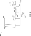
- a three-shaft configuration turbofan engine 701 is shown in block diagram form in Figure 7 .
- the engine 701 comprises a fan 702 located in a duct 703, which fan is driven by a core gas turbine 704.
- the core gas turbine 704 comprises, in axial flow series, an intermediate-pressure compressor 705, a high-pressure compressor 706, a combustor 707, a high-pressure turbine 708, an intermediate-pressure turbine 709, and a low-pressure turbine 710.
- the fan 702 is driven directly by the low-pressure turbine 710 via an interconnecting shaft 711. Together, the fan 702, the low-pressure turbine 710 and interconnecting shaft 711 form the low-pressure spool.
- the intermediate-pressure compressor 705 is driven by the intermediate-pressure turbine 709 via an interconnecting shaft 712, together forming an intermediate-pressure spool.
- the high-pressure compressor 706 is driven by the high-pressure turbine 708 via an interconnecting shaft 713, together forming a high-pressure spool.
- the intermediate-pressure spool is designated the starting spool.
- the same approach for starting engine 101 may be taken with the engine 701, with the combination of permanent magnet alternator and electrical starter-generator together to drive the starting spool via the accessory gearbox 714 and tower shaft arrangement 715 during the engine start procedure.
- the high-pressure spool is designated as the starting spool, and the accessory gearbox 714 and tower shaft arrangement 715 are connected therewith.
Description
- This disclosure relates to electrical start arrangements for gas turbine engines.
- In aerospace, the more electric engine (MEE) and more electric aircraft (MEA) concepts are seen as increasingly attractive paths to reducing fuel consumption. For example, one known aircraft configuration includes electric machines in its engines which are operable as both motors and generators. This facilitates both generation of electrical power during flight and starting of the engine, allowing removal of the air-turbine starter and attendant bleed air ducting. One engine configuration for this known aircraft includes such electric machines coupled to the high-pressure spool of a twin-spool turbofan. Another includes such electric machines coupled to the intermediate-pressure spool of a triple-spool turbofan.
- A problem associated with this approach is found in terms of the torque-speed characteristic required for starting the engine. Typically, one spool of a gas turbine engine, such as the high-pressure spool, is designated the starting spool, and must be rotated at a sufficient rotational rate ωs to deliver the requisite pressure rise across the compressor to initiate combustion. To achieve this, sufficient torque τs must be applied to the spool. The value of both ωs and τs differ substantially from the torque-speed requirements during mission phases when power is being generated - ωs tends to be lower than the spool rotational speed at idle and above, and τs tends to be greater than the spool torque required to generate the required levels of electrical power. In turn, this leads to electric machine designs which, when considering the generation mode of operation, are oversized and thus heavier than required.
- International Patent Application publication
WO 2007/146246 A2 relates to a dual-structured starter/generator for an aircraft engine. - US Patent Application publication
US 2006/087123 A1 relates to a dual-rotor, single input/output starter generator. - International Patent Application publication
WO 95/02120 A1 - The scope of protection is defined by the appended claims.
- In an aspect, there is provided a gas turbine engine comprising:
- an electronic engine controller, EEC;
- one or more spools, one of which is designated a starting spool for starting the engine, and which has a required starting torque τs;
- a permanent magnet alternator mechanically coupled with the starting spool, the alternator being configured to, in a motor mode, provide a peak torque of τa, and, in a generator mode, generate electrical power for the EEC;
- an electrical starter-generator mechanically coupled with the starting spool, the starter-generator being configured to, in a motor mode, provide a peak torque of τsg, and, in a generator mode, generate electrical power for an external load;
- wherein τsg + τa ≥ τs and τsg, τa < τs, and the electronic engine controller is configured to, during a start procedure, operate both the permanent magnet alternator and the starter-generator in a motor mode to drive the starting spool.
- In an embodiment, a switch is configured to, following the start procedure, electrically isolate the permanent magnet alternator and the EEC from the electrical starter-generator and the external load. In an embodiment, the gas turbine engine further comprises:
- a dc bus for supplying power to the EEC and an aircraft electrical power supply;
- a bidirectional power control unit, PCU having an ac side connected to the permanent magnet alternator and a dc side connected to the dc bus, the bidirectional PCU configured to convert between ac and dc;
- a bidirectional power converter having an ac side connected to the electric starter-generator and a dc side connected to the dc bus, the bidirectional power converter configured to convert between ac and dc;
- a switch provided between a connection of the PCU and EEC to the bus and a connection of the bidirectional power converter to the bus, wherein the PCU and the bidirectional power converter can receive power via an aircraft interface for connection with the aircraft electrical power supply during the start procedure with the switch closed, following which the switch can be opened to isolate the PCU and the EEC from the aircraft electrical power supply.
- In an embodiment, the one or more spools comprises:
- a high-pressure spool having a high-pressure compressor driven by a high-pressure turbine; and
- a low-pressure spool having a low-pressure compressor driven by a low-pressure turbine.
- In an embodiment, the high-pressure spool is designated as the starting spool.
- In an embodiment, the low-pressure spool further comprises a fan driven by the low-pressure turbine.
- In an embodiment, the fan is driven by the low-pressure turbine via a reduction gearbox.
- In an embodiment, the one or more spools comprises:
- a high-pressure spool having a high-pressure compressor driven by a high-pressure turbine; and
- an intermediate-pressure spool having an intermediate-pressure compressor driven by an intermediate-pressure turbine.
- a low-pressure spool having a fan driven by a low-pressure turbine;
- In an embodiment, the high-pressure spool is designated as the starting spool.
- In an embodiment, the intermediate-pressure spool is designated as the starting spool.
- In an embodiment, the electrical starter-generator is one of:
- a wound-field synchronous electric machine;
- a permanent magnet synchronous electric machine.
- In an embodiment, the permanent magnet alternator comprises a plurality of stator winding sets.
- In another aspect there is provided a method of starting a gas turbine engine of the type comprising:
- one or more spools, one of which is designated a starting spool for starting the engine, and which has a required starting torque τs;
- a permanent magnet alternator mechanically coupled with the starting spool, the alternator being configured to, in a motor mode, provide a peak torque of τa, and, in a generator mode, generate electrical power for the electronic engine controller;
- an electrical starter-generator mechanically coupled with the starting spool, the starter-generator being configured to, in a motor mode, provide a peak torque of τsg, and, in a generator mode, generate electrical power for an external load;
- wherein τsg + τa ≥ τs and τsg, τa < τs;
- said method comprising operating both the permanent magnet alternator and the starter-generator in a motor mode to drive the starting spool.
- In an embodiment, the one or more spools comprises:
- a high-pressure spool having a high-pressure compressor driven by a high-pressure turbine; and
- a low-pressure spool having a low-pressure compressor driven by a low-pressure turbine.
- In an embodiment, the high-pressure spool is designated as the starting spool.
- In an embodiment, the low-pressure spool further comprises a fan driven by the low-pressure turbine.
- In an embodiment, the electrical starter-generator is one of:
- a wound-field synchronous electric machine;
- a permanent magnet synchronous electric machine.
- Embodiments will now be described by way of example only with reference to the accompanying drawings, and in which:
-
Figure 1 shows a first embodiment of a turbofan engine; -
Figure 2 shows the configuration of the start arrangement for the engine ofFigure 1 ; -
Figures 3A and 3B are, respectively, plots of start spool rotational speed against time, and start spool torque against time; -
Figures 4A and 4B are plots of the torque-speed characteristics of a prior art electrical starter-generator; -
Figures 5A and 5B are plots of the torque-speed characteristics of the electrical starter-generator ofFigure 2 ; -
Figure 6 shows an alternative turbofan engine; -
Figure 7 shows another alternative turbofan engine. - A block diagram illustrating an
engine 101 for an aircraft is shown inFigure 1 . In the present embodiment, theengine 101 is of turbofan configuration, and thus comprises aducted fan 102 that receives intake air A and generates two pressurised airflows: a bypass flow B which passes axially through abypass duct 103 and a core flow C which enters acore gas turbine 104. - The
core gas turbine 104 comprises, in axial flow series, a low-pressure compressor 105, a high-pressure compressor 106, acombustor 107, a high-pressure turbine 108, and a low-pressure turbine 109. - In operation, the core flow C is compressed by the low-
pressure compressor 105 and is then directed into the high-pressure compressor 106 where further compression takes place. The compressed air exhausted from the high-pressure compressor 106 is directed into thecombustor 107 where it is mixed with fuel and the mixture is combusted. The resultant hot combustion products then expand through, and thereby drive, the high-pressure turbine 108 and thereafter the low-pressure turbine 109 before being exhausted through a core nozzle (not shown) to provide a proportion of the overall thrust. - The high-
pressure turbine 108 drives the high-pressure compressor 106 via an interconnectingshaft 110. The low-pressure turbine 109 drives the low-pressure compressor 105 via another interconnectingshaft 111. Together, the high-pressure compressor 106, high-pressure turbine 108, and associated interconnectingshaft 110 form a high-pressure spool of theengine 101. Similarly, the low-pressure compressor 105, low-pressure turbine 109, and associated interconnectingshaft 111 form a low-pressure spool of theengine 101. Such nomenclature will be familiar to those skilled in the art. - In the present embodiment, the
engine 101 is a geared turbofan, whereby thefan 102 is driven by the low-pressure turbine 109 via areduction gearbox 112. In the present embodiment, thereduction gearbox 112 is an epicyclic gearbox. In the particular configuration illustrated inFigure 1 , the epicyclic gearbox is a planetary-configuration epicyclic gearbox. Thus, the low-pressure turbine 109 is connected with a sun gear of thegearbox 112, which is meshed with a plurality of planet gears located in a rotating carrier, which planet gears are in turn are meshed with a static ring gear. The rotating carrier drives thefan 102 via anoutput shaft 113. - It will be appreciated that in alternative embodiments a starconfiguration epicyclic gearbox (in which the planet carrier is static and the ring gear rotates and provides the output) may be used instead. Furthermore, different reduction gearbox configurations could also be used, such as step-aside, layshaft, etc.
- Engine accessories are driven, in this embodiment, by an accessory gearbox (AGB) 114. In the present embodiment, the
accessory gearbox 114 is driven by the high-pressure spool. In this specific embodiment, theaccessory gearbox 114 is driven via atower shaft arrangement 115 of known configuration. The engine accessories include, in the present example, a fuel pump, a permanent magnet alternator (PMA), and an electrical starter-generator (ESG). The configuration and operation of these accessories will be described further with reference toFigure 2 . Other accessories may be provided depending on the chosen configuration of the engine; for example, a hydraulic pump may also be driven via the accessory gearbox. In alternative embodiments, the permanent magnet alternator and electrical starter-generator may be directly connected with the high-pressure spool in an embedded configuration. - Various embodiments of the
engine 101 may include one or more of the following features. - It will be appreciated that instead of being a turbofan having a ducted fan arrangement, the
engine 101 may instead be a turboprop comprising a propeller for producing thrust. - The low- and high-
pressure compressors pressure compressors - The low- and high-
pressure turbines - The
fan 102 may have any desired number of fan blades, for example 16, 18, 20, or 22 fan blades. - Each fan blade may be defined as having a radial span extending from a root (or hub) at a radially inner gas-washed location, or 0 percent span position, to a tip at a 100 percent span position. The ratio of the radius of the fan blade at the hub to the radius of the fan blade at the tip - the hub-tip ratio - may be less than (or on the order of) any of: 0.4, 0.39, 0.38 0.37, 0.36, 0.35, 0.34, 0.33, 0.32, 0.31, 0.3, 0.29, 0.28, 0.27, 0.26, or 0.25. The hub-tip ratio may be in an inclusive range bounded by any two of the aforesaid values (i.e. the values may form upper or lower bounds). The hub-tip ratio may both be measured at the leading edge (or axially forwardmost) part of the blade. The hub-tip ratio refers, of course, to the gas-washed portion of the fan blade, i.e. the portion radially outside any platform.
- The radius of the
fan 102 may be measured between the engine centreline and the tip of a fan blade at its leading edge. The fan diameter may be greater than (or on the order of) any of: 2.5 metres, 2.6 metres, 2.7 metres, 2.8 metres, 2.9 metres, 3 metres, 3.1 metres, 3.2 metres, 3.3 metres, 3.4 metres, 3.5 metres, 3.6 metres, 3.7 metres, 3.8 metres or 3.9 metres. The fan diameter may be in an inclusive range bounded by any two of the aforesaid values (i.e. the values may form upper or lower bounds). - The rotational speed of the
fan 102 may vary in use. Generally, the rotational speed is lower for fans with a higher diameter. Purely by way of non-limitative example, the rotational speed of the fan at cruise conditions may be less than 2500 rpm, for example 2300 rpm. Purely by way of further non-limitative example, the rotational speed of thefan 102 at cruise conditions for an engine having a fan diameter in the range of from 2.5 metres to 3 metres (for example 2.5 metres to 2.8 metres) may be in the range of from 1700 rpm to 2500 rpm, for example in the range of from 1800 rpm to 2300 rpm, or, for example in the range of from 1900 rpm to 2100 rpm. Purely by way of further non-limitative example, the rotational speed of the fan at cruise conditions for an engine having a fan diameter in the range of from 3.2 metres to 3.8 metres may be in the range of from 1200 rpm to 2000 rpm, for example in the range of from 1300 rpm to 1800 rpm, for example in the range of from 1400 rpm to 1600 rpm. - In use of the
engine 101, the fan 102 (with its associated fan blades) rotates about a rotational axis. This rotation results in the tip of the fan blade moving with a velocity Utip. The work done by the fan blades on the flow results in an enthalpy rise dH of the flow. A fan tip loading may be defined as dH/Utip 2, where dH is the enthalpy rise (for example the one-dimensional average enthalpy rise) across the fan and Utip is the (translational) velocity of the fan tip, for example at the leading edge of the tip (which may be defined as fan tip radius at leading edge multiplied by angular speed). The fan tip loading at cruise conditions may be greater than (or on the order of) any of: 0.3, 0.31, 0.32, 0.33, 0.34, 0.35, 0.36, 0.37, 0.38, 0.39 or 0.4. The fan tip loading may be in an inclusive range bounded by any two of the values in the previous sentence (i.e. the values may form upper or lower bounds). - The
engine 101 may have any desired bypass ratio, where the bypass ratio is defined as the ratio of the mass flow rate of the flow B through the bypass duct to the mass flow rate of the flow C through the core at cruise conditions. Depending upon the selected configuration, the bypass ratio may be greater than (or on the order of) any of the following: 10, 10.5, 11, 11.5, 12, 12.5, 13, 13.5, 14, 14.5, 15, 15.5, 16, 16.5, or 17. The bypass ratio may be in an inclusive range bounded by any two of the aforesaid values (i.e. the values may form upper or lower bounds). The bypass duct may be substantially annular. The bypass duct may be radially outside the core engine. The radially outer surface of the bypass duct may be defined by a nacelle and/or a fan case. - The overall pressure ratio of the
engine 101 may be defined as the ratio of the stagnation pressure upstream of thefan 102 to the stagnation pressure at the exit of the high-pressure compressor 106 (before entry into the combustor). By way of non-limitative example, the overall pressure ratio of theengine 101 at cruise may be greater than (or on the order of) any of the following: 35, 40, 45, 50, 55, 60, 65, 70, 75. The overall pressure ratio may be in an inclusive range bounded by any two of the aforesaid values (i.e. the values may form upper or lower bounds). - Specific thrust of the
engine 101 may be defined as the net thrust of the engine divided by the total mass flow through theengine 101. At cruise conditions, the specific thrust of theengine 101 may be less than (or on the order of) any of the following: 110 Nkg-1s, 105 Nkg-1s, 100 Nkg-1s, 95 Nkg-1s, 90 Nkg-1s, 85 Nkg-1s, or 80 Nkg-1s. The specific thrust may be in an inclusive range bounded by any two of the values in the previous sentence (i.e. the values may form upper or lower bounds). Such engines may be particularly efficient in comparison with conventional gas turbine engines. - The
engine 101 may have any desired maximum thrust. For example, theengine 101 may be capable of producing a maximum thrust of at least (or on the order of) any of the following: 160 kilonewtons, 170 kilonewtons, 180 kilonewtons, 190 kilonewtons, 200 kilonewtons, 250 kilonewtons, 300 kilonewtons, 350 kilonewtons, 400 kilonewtons, 450 kilonewtons, 500 kilonewtons, or 550 kilonewtons. The maximum thrust may be in an inclusive range bounded by any two of the aforesaid values (i.e. the values may form upper or lower bounds). The thrust referred to above may be the maximum net thrust at standard atmospheric conditions at sea level plus 15 degrees Celsius (ambient pressure 101.3 kilopascals, temperature 30 degrees Celsius), with theengine 101 being static. - In use, the temperature of the flow at the entry to the high-
pressure turbine 108 may be particularly high. This temperature, which may be referred to as turbine entry temperature or TET, may be measured at the exit to thecombustor 107, for example immediately upstream of the first turbine vane, which itself may be referred to as a nozzle guide vane. At cruise, the TET may be at least (or on the order of) any of the following: 1400 kelvin, 1450 kelvin, 1500 kelvin, 1550 kelvin, 1600 kelvin or 1650 kelvin. The TET at cruise may be in an inclusive range bounded by any two of the aforesaid values (i.e. the values may form upper or lower bounds). The maximum TET in use of theengine 101 may be, for example, at least (or on the order of) any of the following: 1700 kelvin, 1750 kelvin, 1800 kelvin, 1850 kelvin, 1900 kelvin, 1950 kelvin or 2000 kelvin. The maximum TET may be in an inclusive range bounded by any two of the aforesaid values (i.e. the values may form upper or lower bounds). The maximum TET may occur, for example, at a high thrust condition, for example at a maximum take-off (MTO) condition. - A fan blade and/or aerofoil portion of a fan blade described and/or claimed herein may be manufactured from any suitable material or combination of materials. For example, at least a part of the fan blade and/or aerofoil may be manufactured at least in part from a composite, for example a metal matrix composite and/or an organic matrix composite, such as carbon fibre. By way of further example at least a part of the fan blade and/or aerofoil may be manufactured at least in part from a metal, such as a titanium-based metal or an aluminium based material (such as an aluminium-lithium alloy) or a steel-based material. The fan blade may comprise at least two regions manufactured using different materials. For example, the fan blade may have a protective leading edge, which may be manufactured using a material that is better able to resist impact (for example from birds, ice or other material) than the rest of the blade. Such a leading edge may, for example, be manufactured using titanium or a titanium-based alloy. Thus, purely by way of example, the fan blade may have a carbon-fibre or aluminium-based body with a titanium leading edge.
- The
fan 102 may comprise a central hub portion, from which the fan blades may extend, for example in a radial direction. The fan blades may be attached to the central portion in any desired manner. For example, each fan blade may comprise a fixture which may engage a corresponding slot in the hub. Purely by way of example, such a fixture may be in the form of a dovetail that may slot into and/or engage a corresponding slot in the hub/disc in order to fix the fan blade to the hub. By way of further example, the fan blades maybe formed integrally with a central hub portion. Such an arrangement may be a bladed disc or a bladed ring. Any suitable method may be used to manufacture such a bladed disc or bladed ring. For example, at least a part of the fan blades may be machined from a billet and/or at least part of the fan blades may be attached to the hub/disc by welding, such as linear friction welding. - The
engine 101 may be provided with a variable area nozzle (VAN). Such a variable area nozzle may allow the exit area of the bypass duct to be varied in use. The general principles of the present disclosure may apply to engines with or without a VAN. - As used herein, cruise conditions have the conventional meaning and would be readily understood by those skilled in the art.
- Such cruise conditions may be conventionally defined as the conditions at mid-cruise, for example the conditions experienced by the aircraft and/or engine at the midpoint (in terms of time and/or distance) between top of climb and start of descent. Cruise conditions thus define an operating point of the gas turbine engine which provides a thrust that would ensure steady state operation (i.e. maintaining a constant altitude and constant Mach number) at mid-cruise of an aircraft to which it is designed to be attached, taking into account the number of engines provided to that aircraft. For example, where an engine is designed to be attached to an aircraft that has two engines of the same type, at cruise conditions the engine provides half of the total thrust that would be required for steady state operation of that aircraft at mid-cruise.
- In other words, for a given gas turbine engine for an aircraft, cruise conditions are defined as the operating point of the engine that provides a specified thrust (required to provide - in combination with any other engines on the aircraft - steady state operation of the aircraft to which it is designed to be attached at a given mid-cruise Mach number) at the mid-cruise atmospheric conditions (defined by the International Standard Atmosphere according to ISO 2533 at the mid-cruise altitude). For any given gas turbine engine for an aircraft, the mid-cruise thrust, atmospheric conditions and Mach number are known, and thus the operating point of the engine at cruise conditions is clearly defined.
- The cruise conditions may correspond to ISA standard atmospheric conditions at an altitude that is in the range of from 10000 to 15000 metres, such as from 10000 to 12000 metres, or from 10400 to 11600 metres (around 38000 feet), or from 10500 to 11500 metres, or from 10600 to 11400 metres, or from 10700 metres (around 35000 feet) to 11300 metres, or from 10800 to 11200 metres, or from 10900 to 11100 metres, or 11000 metres. The cruise conditions may correspond to standard atmospheric conditions at any given altitude in these ranges.
- The forward speed at the cruise condition may be any point in the range of from Mach 0.7 to 0.9, for example one of Mach 0.75 to 0.85, Mach 0.76 to 0.84, Mach 0.77 to 0.83, Mach 0.78 to 0.82, Mach 0.79 to 0.81, Mach 0.8, Mach 0.85, or in the range of from Mach 0.8 to 0.85. Any single speed within these ranges may be the cruise condition. For some aircraft, the cruise conditions may be outside these ranges, for example below Mach 0.7 or above Mach 0.9.
- Thus, for example, the cruise conditions may correspond specifically to a pressure of 23 kilopascals, a temperature of minus 55 degrees Celsius, and a forward Mach number of 0.8.
- It will of course be appreciated, however, that the principles of the invention claimed herein may still be applied to engines having suitable design features falling outside of the aforesaid parameter ranges.
- The arrangement of engine accessories is shown in
Figure 2 . - As described previously, in the present embodiment the
accessory gearbox 114 is mechanically coupled to and drives afuel pump 201, apermanent magnet alternator 202, and an electrical starter-generator 203. As electrical starter-generator 203 is mechanically coupled with the high-pressure spool of theengine 101 via, in this embodiment, theaccessory gearbox 114 andtower shaft arrangement 115, the high-pressure spool is designated the starting spool for theengine 101. - In an embodiment, the
permanent magnet alternator 202 comprises a plurality of stator winding sets for the purposes of redundancy. In a specific embodiment, each winding set comprises three phases connected in a star arrangement. A delta connection could be used instead depending on, for example, the grounding scheme etc. A different number of phases could be provided depending upon, for example, the size of the alternator. In a specific embodiment, four winding sets are provided to meet the requisite degree of redundancy. - In an embodiment, the electrical starter-
generator 203 is a wound-field electric machine, having a wound rotor whose field is generated by an exciter. Such machine types are currently used in service as electrical starter-generators. In another embodiment, the electrical starter-generator 203 is a permanent magnet electric machine, having a permanent magnet rotor to improve power density. - Control of the operation of the
engine 101 is performed by an electronic engine controller (EEC) 204. Data interfaces facilitating control of engine components are represented as dashed lines in the Figure. In the present embodiment theEEC 204 is a full-authority digital engine controller (FADEC), the configuration of which will be known and understood by those skilled in the art. It therefore controls all aspects of theengine 101. Control of fuel metering is achieved by provision of a fuel metering unit (FMU) 205 of known configuration. Thefuel metering unit 205 supplies fuel tofuel injectors 206 in thecombustor 107. - Conversion from alternating current (ac) produced by the
permanent magnet alternator 202 into direct current (dc) is performed by a bidirectional power control unit (PCU) 207. Conversion from alternating current produced by the electrical starter-generator 203 into direct current is performed by abidirectional power converter 208. Provision of bidirectional power conversion apparatus allows the starting spool to be driven electrically during a start procedure. - In the present embodiment, the dc sides of the
power control unit 207 and thebidirectional power converter 208 interface with adc bus 209. Thedc bus 209 supplies power for operation of theelectronic engine controller 204. Thedc bus 209 may also supply power for other electrical loads on the engine (not shown). In the present example, thedc bus 209 comprises anaircraft interface 210 for connection with an aircraft electrical supply. This enables thedc bus 209 to deliver power to an aircraft on which theengine 101 is installed, and similarly receive power from aircraft-side energy storage such as batteries, or other power sources such as an auxiliary power unit (APU) or another engine. It will be appreciated that thedc bus 209 could instead be an ac bus, either operating at fixed or variable frequency, with additional power conversion apparatus provided to provide voltage conversion, frequency conversion, etc. - In order to facilitate isolation of the
permanent magnet alternator 202,power control unit 207, andelectronic engine controller 204 from the electrical starter-generator 203 andaircraft interface 210 following engine start, aswitch 211 is provided between the connection of thepower control unit 207 andelectronic engine controller 204 to thebus 209, and the connection of thebidirectional power converter 208 to thebus 209. In this way, both thepower control unit 207 and thebidirectional power converter 208 may receive power via theaircraft interface 210 during engine start with theswitch 211 closed, following which theswitch 211 may be opened to isolate thepower control unit 207 andelectronic engine controller 204 from theaircraft interface 210. In a specific embodiment, theswitch 211 are dc contactors, which as will be familiar to those skilled in the art are electricallycontrolled switches used for switching an electrical power circuit, where the control circuit has a lower power level than the switched circuit. - In order to initiate combustion of fuel in the
combustor 107 during a start procedure, anignition unit 212 of known configuration is provided which operates under control of theelectronic engine controller 204. Theignition unit 212 operatesigniters 213 in thecombustor 107 for initiating the combustion process. - In order to start the
engine 101, the starting spool must be rotated at a minimum speed to deliver sufficient mass flow to thecombustor 107. - A plot of the rotational speed ω of the high-pressure spool with respect to time during the starting process is shown in
Figure 3A . Initially, the rotational speed ω is increased to a speed ω1. After the airflow has stabilised and any remnant fuel from the previous cycle is purged from the flowpath, theelectronic engine controller 204 begins the ignition process at time t1. In particular, thefuel metering unit 205 begins to deliver fuel by theinjectors 206, and theignition unit 212 energises theigniters 213. With the combustion process initiated, the rotational speed ω increases again until an idle speed ω2 is reached at t2, whereupon theignition unit 212 may be disabled. - A plot of the external torque τ required to drive the high-pressure spool during the starting process is shown in
Figure 3B . Initially, a starting torque τs must be applied until time t1 whereupon the products of the combustion process begin to drive the high-pressure turbine 110. As the non-dimensional flow (a function of mass flow, temperature and pressure) through the high-pressure turbine 110 begins to increase, so too does the torque it produces. Thus, the required external torque from time t1 to t2 decreases. - As described in the introduction, many prior art engines provided the external torque required for starting, τs, by means of an air turbine starter. A small number of engine types provide the starting torque an electrical starter-generator.
- A torque-speed characteristic for a prior art electrical starter-generator is shown in
Figure 4A . Operating points of the engine are shown on the plot with starting point S being the combination of torque and speed required to start the engine, and generating points G being the combination of torque and speed required to generate various levels of power during operation. Lines of constant power are also shown on the chart for the various points S, G. In this example, the electrical starter-generator is designed for operation in constant-torque mode, and thus is capable of delivering full rated torque τs over the full range of speeds ω. It will be noted, therefore, that the torque-speed capability of the electrical starter-generator far exceeds that required by the generating points G. - As shown in
Figure 4B , field weakening control may be used to operate a prior art electrical starter-generator in a constant-power mode for the generating points G. This allows a reduction in size of the starter-generator as the peak torque-speed value is now the starting point S. However, even the constant-power line which passes through starting point S substantially exceeds the generating point G with the highest power demand, resulting in an electrical starter-generator which is over-specified for the generating points G. It should be noted that field weakening operates by reducing the field to in turn reduce back-emf, allowing a larger current to flow in the armature. In permanent magnet drives in particular, failure of the power electronic converter implementing the field-weakening control results in the restoration of the full field, and thus a significant overvoltage condition. This can be detrimental to the safety of the entire electrical system. - It will therefore be appreciated from
Figures 4A and 4B that no matter the control scheme for the motor, it is the starting point S which sizes this prior art electrical starter-generator in terms of its design parameters. Most notably, for a fixed machine type and technology level, the volume of the electrical starter-generator and its weight will be determined by this starting point S. It will therefore be appreciated that the asymmetry in terms of the torque-speed combination required for starting the engine results in a larger and heavier design than if it was only designed for generating power during flight. - Thus in
engine 101, the permanent magnet alternator is also operated during the starting process. A permanent magnet alternator may be a mandated safety requirement and may therefore be required to be present, and indeed said safety requirements may preclude its function being replaced by the electrical starter-generator. - A plot of the torque-speed characteristic of the electrical starter-
generator 203 is shown inFigure 5A . In this embodiment, the electrical starter-generator 203 is adapted to operate in a constant-torque mode of operation. As shown in the plot, the peak torque τsg of the electrical starter-generator 203 is less than the torque τs for rotating the high-pressure spool. This shortfall, shown in the hatched region 411, is made up in the present embodiment by the peak torque capability of the permanent magnet alternator 402, τa. Thus, whilst both τsg and τa are less than τs, the combination of τsg and τa is greater than τs. As can be seen, however, the electrical starter-generator 203 is still capable of operating at its required generating points 412. In this way, the asymmetry in terms of specification between the starter and the generator modes of operation is reduced. - Another plot of the torque-speed characteristic of the electrical starter-
generator 203 is shown inFigure 5B . In this embodiment, the electrical starter-generator 203 andbidirectional power converter 208 are configured to implement field weakening to operate in a constant-power mode above speed ω1. It will be seen from this plot that the constant-power line of the electrical starter-generator 203 is appreciably lower than that of the prior art electrical starter-generator shown inFigure 4B . As described previously, the use (or not) of field weakening to facilitate a reduction in size of the electric machine may be determined by, for example, the selected level of integrity and redundancy in thebidirectional power converter 208 which implements the field weakening. - In an example, τs was 250 Nm and ω1 is 5000 rpm. The peak generating point 402/412 was 100 Nm at 15000 rpm. Utilising the prior art configuration, the weight of an electrical starter-generator meeting these requirements was 38 kg. By utilising the combination of the
permanent magnet alternator 202 and the electrical starter-generator 203, it was possible to meet the τs requirement with an electrical starter-generator torque τsg of 230 Nm and a permanent magnet alternator torque of 20 Nm at ω1. This resulted in a reduction in the weight of the electrical starter-generator of 3 kg. - A two-shaft
configuration turbofan engine 601 is shown in block diagram form inFigure 6 . Theengine 601 comprises afan 602 located in aduct 603, which fan is driven by acore gas turbine 604. Thecore gas turbine 604 comprises, in axial flow series, a low-pressure compressor 605, a high-pressure compressor 606, acombustor 607, a high-pressure turbine 608, and a low-pressure turbine 609. - The low-
pressure compressor 605 is driven by the low-pressure turbine 609 via an interconnectingshaft 610. In this configuration, no reduction gearbox is used and thefan 602 is driven directly by the low-pressure turbine 609. Together, thefan 602, the low-pressure compressor 605, the low-pressure turbine 609 and interconnectingshaft 610 form the low-pressure spool. The high-pressure compressor 606 is driven by the high-pressure turbine 608 via an interconnectingshaft 611, together form ing a high-pressure spool. In this configuration, the high-pressure spool is designated as the starting spool. - The same approach for starting
engine 101 may be taken with theengine 601, with the combination of permanent magnet alternator and electrical starter-generator being used together to drive the starting spool via theaccessory gearbox 612 andtower shaft arrangement 613 during the engine start procedure. - A three-shaft
configuration turbofan engine 701 is shown in block diagram form inFigure 7 . Theengine 701 comprises afan 702 located in aduct 703, which fan is driven by acore gas turbine 704. Thecore gas turbine 704 comprises, in axial flow series, an intermediate-pressure compressor 705, a high-pressure compressor 706, acombustor 707, a high-pressure turbine 708, an intermediate-pressure turbine 709, and a low-pressure turbine 710. - The
fan 702 is driven directly by the low-pressure turbine 710 via an interconnectingshaft 711. Together, thefan 702, the low-pressure turbine 710 and interconnectingshaft 711 form the low-pressure spool. The intermediate-pressure compressor 705 is driven by the intermediate-pressure turbine 709 via an interconnectingshaft 712, together forming an intermediate-pressure spool. The high-pressure compressor 706 is driven by the high-pressure turbine 708 via an interconnectingshaft 713, together forming a high-pressure spool. - In the present embodiment, the intermediate-pressure spool is designated the starting spool. The same approach for starting
engine 101 may be taken with theengine 701, with the combination of permanent magnet alternator and electrical starter-generator together to drive the starting spool via theaccessory gearbox 714 andtower shaft arrangement 715 during the engine start procedure. - In an alternative embodiment, the high-pressure spool is designated as the starting spool, and the
accessory gearbox 714 andtower shaft arrangement 715 are connected therewith.
Claims (15)
- A gas turbine engine (101, 601, 701) comprising:an electronic engine controller, EEC, (204);one or more spools, one of which is designated a starting spool for starting the engine, and which has a required starting torque τs;a permanent magnet alternator (202) mechanically coupled with the starting spool and configured, in a generator mode, to generate electrical power for the EEC (204); andan electrical starter-generator (203) mechanically coupled with the starting spool, the starter-generator being configured to, in a motor mode, provide a peak torque of τsg, and, in a generator mode, generate electrical power for an external load,wherein:the permanent magnet alternator is operable in a motor mode and is configured, in the motor mode, to provide a peak torque of τa;
 the EEC (204) is configured to, during a start procedure, operate both the permanent magnet alternator and the starter-generator in a motor mode to drive the starting spool.
 - The gas turbine engine (101, 601, 701) of claim 1, further comprising a switch (211), wherein the switch (211) is configured to, following the start procedure, electrically isolate the permanent magnet alternator (202) and the EEC (204) from the electrical starter-generator (203) and the external load.
- The gas turbine engine (101, 601, 701) of claim 1 or claim 2, further comprising:a dc bus (209) for supplying power to the EEC (204) and an aircraft electrical power supply;a bidirectional power control unit, PCU (207) having an ac side connected to the permanent magnet alternator and a dc side connected to the dc bus (209), the bidirectional PCU configured to convert between ac and dc;a bidirectional power converter (208) having an ac side connected to the electric starter-generator (203) and a dc side connected to the dc bus (209), the bidirectional power converter configured to convert between ac and dc;wherein a/the switch (211) is provided between a connection of the PCU (207) and EEC (204) to the bus (209) and a connection of the bidirectional power converter (208) to the bus (209), wherein the PCU (207) and the bidirectional power converter (208) can receive power via an aircraft interface (210) for connection with the aircraft electrical power supply during the start procedure with the switch (211) closed following which the switch (211) can be opened to isolate the PCU (207) and the EEC (204) from the aircraft electrical power supply.
- The gas turbine engine (101, 601) of any one of the preceding claims, in which the one or more spools comprises:a high-pressure spool having a high-pressure compressor (106) driven by a high-pressure turbine (108); anda low-pressure spool having a low-pressure compressor (105) driven by a low-pressure turbine (109).
- The gas turbine engine (101, 601) of claim 4, in which the high-pressure spool is designated as the starting spool.
- The gas turbine engine (101, 601) of claim 4 or claim 5, in which the low-pressure spool further comprises a fan (102) driven by the low-pressure turbine (109).
- The gas turbine engine (101) of claim 6, in which the fan (102) is driven by the low-pressure turbine (109) via a reduction gearbox (112).
- The gas turbine engine (701) of any one of claims 1 to 3, in which the one or more spools comprises:a high-pressure spool having a high-pressure compressor (706) driven by a high-pressure turbine (708); andan intermediate-pressure spool having an intermediate-pressure compressor (705) driven by an intermediate-pressure turbine (709);a low-pressure spool having a fan (702) driven by a low-pressure turbine (710).
- The gas turbine engine (701) of claim 8, in which the high-pressure spool is designated as the starting spool.
- The gas turbine engine (701) of claim 8, in which the intermediate-pressure spool is designated as the starting spool.
- The gas turbine engine (101, 601, 701) of any preceding claim, in which the electrical starter-generator (203) is one of:a wound-field synchronous electric machine;a permanent magnet synchronous electric machine.
- The gas turbine engine (101, 601, 701) of any preceding claim, in which the permanent magnet alternator comprises a plurality of stator winding sets.
- A method of starting a gas turbine engine (101, 601, 701) of the type comprising:an electronic engine controller, EEC (204)one or more spools, one of which is designated a starting spool for starting the engine, and which has a required starting torque τs;a permanent magnet alternator (202) mechanically coupled with the starting spool, the alternator being configured to, in a generator mode, generate electrical power for the electronic engine controller (204);an electrical starter-generator (203) mechanically coupled with the starting spool, the starter-generator being configured to, in a motor mode, provide a peak torque of τsg, and, in a generator mode, generate electrical power for an external load;wherein:the permanent magnet alternator is operable in a motor mode and is configured, in the motor mode, to provide a peak torque of τa;
 said method comprises operating both the permanent magnet alternator (202) and the starter-generator (203) in a motor mode to drive the starting spool.
 - The method of claim 13, in which the one or more spools comprises:a high-pressure spool having a high-pressure compressor (106, 606) driven by a high-pressure turbine (108, 608); anda low-pressure spool having a low-pressure compressor (105 605), driven by a low-pressure turbine (109, 609).
- The method of claim 13, in which the high-pressure spool is designated as the starting spool.
Applications Claiming Priority (1)
| Application Number | Priority Date | Filing Date | Title |
|---|---|---|---|
| GBGB2011841.0A GB202011841D0 (en) | 2020-07-30 | 2020-07-30 | Gas turbine engine |
Publications (2)
| Publication Number | Publication Date |
|---|---|
| EP3945203A1 EP3945203A1 (en) | 2022-02-02 |
| EP3945203B1 true EP3945203B1 (en) | 2024-01-31 |
Family
ID=72425202
Family Applications (1)
| Application Number | Title | Priority Date | Filing Date |
|---|---|---|---|
| EP21183331.4A Active EP3945203B1 (en) | 2020-07-30 | 2021-07-02 | Gas turbine engine |
Country Status (3)
| Country | Link |
|---|---|
| US (1) | US11512644B2 (en) |
| EP (1) | EP3945203B1 (en) |
| GB (1) | GB202011841D0 (en) |
Families Citing this family (2)
| Publication number | Priority date | Publication date | Assignee | Title |
|---|---|---|---|---|
| EP4148250A1 (en) * | 2021-09-08 | 2023-03-15 | Rolls-Royce plc | An improved gas turbine engine |
| US20230228216A1 (en) * | 2022-01-19 | 2023-07-20 | General Electric Company | Bleed flow assembly for a gas turbine engine |
Family Cites Families (9)
| Publication number | Priority date | Publication date | Assignee | Title |
|---|---|---|---|---|
| GB9313905D0 (en) * | 1993-07-06 | 1993-08-25 | Rolls Royce Plc | Shaft power transfer in gas turbine engines |
| US7285871B2 (en) | 2004-08-25 | 2007-10-23 | Honeywell International, Inc. | Engine power extraction control system |
| US20060087123A1 (en) * | 2004-10-22 | 2006-04-27 | Stout David E | Dual-rotor, single input/output starter-generator |
| US7242105B2 (en) * | 2005-08-17 | 2007-07-10 | Hamilton Sundstrand Corporation | Electric engine start with two motors and single motor drive |
| US7687928B2 (en) * | 2006-06-14 | 2010-03-30 | Smiths Aerospace, Llc | Dual-structured aircraft engine starter/generator |
| US20150330300A1 (en) * | 2013-03-14 | 2015-11-19 | United Technologies Corporation | Two spool engine core with a starter |
| US20170234234A1 (en) * | 2016-02-12 | 2017-08-17 | Hamilton Sundstrand Corporation | Gas turbine engine motoring system for bowed rotor engine starts |
| US10422243B2 (en) * | 2017-01-19 | 2019-09-24 | United Technologies Corporation | Gas turbine engine dual towershaft accessory gearbox and starter generator assembly |
| GB201817229D0 (en) * | 2018-10-23 | 2018-12-05 | Rolls Royce Plc | Epicyclic gearbox |
-
2020
- 2020-07-30 GB GBGB2011841.0A patent/GB202011841D0/en not_active Ceased
-
2021
- 2021-07-02 EP EP21183331.4A patent/EP3945203B1/en active Active
- 2021-07-07 US US17/369,332 patent/US11512644B2/en active Active
Also Published As
| Publication number | Publication date |
|---|---|
| GB202011841D0 (en) | 2020-09-16 |
| EP3945203A1 (en) | 2022-02-02 |
| US11512644B2 (en) | 2022-11-29 |
| US20220049658A1 (en) | 2022-02-17 |
Similar Documents
| Publication | Publication Date | Title |
|---|---|---|
| US20200392924A1 (en) | Varying the bypass ratio of a turbofan engine | |
| US20200392859A1 (en) | Limiting spool speeds in a gas turbine engine | |
| EP3832097B1 (en) | Gas turbine engine | |
| EP3751121B1 (en) | Improving deceleration of a gas turbine | |
| EP3793051B1 (en) | Electrical systems | |
| US20210017914A1 (en) | Reducing idle thrust in a propulsive gas turbine | |
| EP3751116B1 (en) | Generating electrical power at high thrust conditions | |
| EP3945203B1 (en) | Gas turbine engine | |
| US11268454B2 (en) | Preventing surge | |
| EP3751115B1 (en) | Improving acceleration of a gas turbine | |
| US20230332509A1 (en) | Increasing surge margin and compression efficiency via shaft power transfer | |
| GB2571992A (en) | Gas turbine engine and method of maintaining a gas turbine engine | |
| EP3751114B1 (en) | Reducing low flight mach number fuel consumption in a gas turbine with electric machines | |
| GB2584691A (en) | Increasing compression efficiency | |
| GB2584690A (en) | Increasing surge margin via shaft power transfer |
Legal Events
| Date | Code | Title | Description |
|---|---|---|---|
| PUAI | Public reference made under article 153(3) epc to a published international application that has entered the european phase |
Free format text: ORIGINAL CODE: 0009012 |
|
| STAA | Information on the status of an ep patent application or granted ep patent |
Free format text: STATUS: THE APPLICATION HAS BEEN PUBLISHED |
|
| AK | Designated contracting states |
Kind code of ref document: A1 Designated state(s): AL AT BE BG CH CY CZ DE DK EE ES FI FR GB GR HR HU IE IS IT LI LT LU LV MC MK MT NL NO PL PT RO RS SE SI SK SM TR |
|
| STAA | Information on the status of an ep patent application or granted ep patent |
Free format text: STATUS: REQUEST FOR EXAMINATION WAS MADE |
|
| 17P | Request for examination filed |
Effective date: 20220722 |
|
| RBV | Designated contracting states (corrected) |
Designated state(s): AL AT BE BG CH CY CZ DE DK EE ES FI FR GB GR HR HU IE IS IT LI LT LU LV MC MK MT NL NO PL PT RO RS SE SI SK SM TR |
|
| GRAP | Despatch of communication of intention to grant a patent |
Free format text: ORIGINAL CODE: EPIDOSNIGR1 |
|
| STAA | Information on the status of an ep patent application or granted ep patent |
Free format text: STATUS: GRANT OF PATENT IS INTENDED |
|
| GRAS | Grant fee paid |
Free format text: ORIGINAL CODE: EPIDOSNIGR3 |
|
| GRAA | (expected) grant |
Free format text: ORIGINAL CODE: 0009210 |
|
| STAA | Information on the status of an ep patent application or granted ep patent |
Free format text: STATUS: THE PATENT HAS BEEN GRANTED |
|
| INTG | Intention to grant announced |
Effective date: 20231207 |
|
| P01 | Opt-out of the competence of the unified patent court (upc) registered |
Effective date: 20231214 |
|
| AK | Designated contracting states |
Kind code of ref document: B1 Designated state(s): AL AT BE BG CH CY CZ DE DK EE ES FI FR GB GR HR HU IE IS IT LI LT LU LV MC MK MT NL NO PL PT RO RS SE SI SK SM TR |
|
| REG | Reference to a national code |
Ref country code: GB Ref legal event code: FG4D Ref country code: CH Ref legal event code: EP |
|
| REG | Reference to a national code |
Ref country code: DE Ref legal event code: R096 Ref document number: 602021008889 Country of ref document: DE |
|
| REG | Reference to a national code |
Ref country code: IE Ref legal event code: FG4D |