EP3597487B1 - Verstellbare halteanordnung - Google Patents
Verstellbare halteanordnung Download PDFInfo
- Publication number
- EP3597487B1 EP3597487B1 EP19186294.5A EP19186294A EP3597487B1 EP 3597487 B1 EP3597487 B1 EP 3597487B1 EP 19186294 A EP19186294 A EP 19186294A EP 3597487 B1 EP3597487 B1 EP 3597487B1
- Authority
- EP
- European Patent Office
- Prior art keywords
- flexible connector
- base
- channel
- mounting assembly
- electrical harness
- Prior art date
- Legal status (The legal status is an assumption and is not a legal conclusion. Google has not performed a legal analysis and makes no representation as to the accuracy of the status listed.)
- Active
Links
Images



Classifications
-
- B—PERFORMING OPERATIONS; TRANSPORTING
- B60—VEHICLES IN GENERAL
- B60R—VEHICLES, VEHICLE FITTINGS, OR VEHICLE PARTS, NOT OTHERWISE PROVIDED FOR
- B60R16/00—Electric or fluid circuits specially adapted for vehicles and not otherwise provided for; Arrangement of elements of electric or fluid circuits specially adapted for vehicles and not otherwise provided for
- B60R16/02—Electric or fluid circuits specially adapted for vehicles and not otherwise provided for; Arrangement of elements of electric or fluid circuits specially adapted for vehicles and not otherwise provided for electric constitutive elements
- B60R16/0207—Wire harnesses
- B60R16/0215—Protecting, fastening and routing means therefor
-
- F—MECHANICAL ENGINEERING; LIGHTING; HEATING; WEAPONS; BLASTING
- F16—ENGINEERING ELEMENTS AND UNITS; GENERAL MEASURES FOR PRODUCING AND MAINTAINING EFFECTIVE FUNCTIONING OF MACHINES OR INSTALLATIONS; THERMAL INSULATION IN GENERAL
- F16L—PIPES; JOINTS OR FITTINGS FOR PIPES; SUPPORTS FOR PIPES, CABLES OR PROTECTIVE TUBING; MEANS FOR THERMAL INSULATION IN GENERAL
- F16L3/00—Supports for pipes, cables or protective tubing, e.g. hangers, holders, clamps, cleats, clips, brackets
- F16L3/08—Supports for pipes, cables or protective tubing, e.g. hangers, holders, clamps, cleats, clips, brackets substantially surrounding the pipe, cable or protective tubing
- F16L3/12—Supports for pipes, cables or protective tubing, e.g. hangers, holders, clamps, cleats, clips, brackets substantially surrounding the pipe, cable or protective tubing comprising a member substantially surrounding the pipe, cable or protective tubing
- F16L3/123—Supports for pipes, cables or protective tubing, e.g. hangers, holders, clamps, cleats, clips, brackets substantially surrounding the pipe, cable or protective tubing comprising a member substantially surrounding the pipe, cable or protective tubing and extending along the attachment surface
-
- F—MECHANICAL ENGINEERING; LIGHTING; HEATING; WEAPONS; BLASTING
- F01—MACHINES OR ENGINES IN GENERAL; ENGINE PLANTS IN GENERAL; STEAM ENGINES
- F01D—NON-POSITIVE DISPLACEMENT MACHINES OR ENGINES, e.g. STEAM TURBINES
- F01D25/00—Component parts, details, or accessories, not provided for in, or of interest apart from, other groups
- F01D25/28—Supporting or mounting arrangements, e.g. for turbine casing
-
- H—ELECTRICITY
- H02—GENERATION; CONVERSION OR DISTRIBUTION OF ELECTRIC POWER
- H02G—INSTALLATION OF ELECTRIC CABLES OR LINES, OR OF COMBINED OPTICAL AND ELECTRIC CABLES OR LINES
- H02G3/00—Installations of electric cables or lines or protective tubing therefor in or on buildings, equivalent structures or vehicles
- H02G3/30—Installations of cables or lines on walls, floors or ceilings
- H02G3/32—Installations of cables or lines on walls, floors or ceilings using mounting clamps
-
- B—PERFORMING OPERATIONS; TRANSPORTING
- B64—AIRCRAFT; AVIATION; COSMONAUTICS
- B64C—AEROPLANES; HELICOPTERS
- B64C1/00—Fuselages; Constructional features common to fuselages, wings, stabilising surfaces or the like
- B64C1/40—Sound or heat insulation, e.g. using insulation blankets
- B64C1/403—Arrangement of fasteners specially adapted therefor, e.g. of clips
- B64C1/406—Arrangement of fasteners specially adapted therefor, e.g. of clips in combination with supports for lines, e.g. for pipes or cables
Definitions
- Embodiments of the present disclosure pertain to the art of fasteners, and more specifically, to a fastener for use with an electrical harness of an engine.
- At least one electric cable assembly Positioned about the external surface of an engine is at least one electric cable assembly, commonly referred to as an electrical harness.
- electrical harnesses are used to supply electricity to various pieces of peripheral equipment of the engine, such as sensors, computer controls and actuators for example.
- Each electrical harness is handmade and has a diameter and stiffness based on a given application of the harness. Accordingly, there is commonly significant variation between harnesses within a single engine.
- Each engine harness is generally held in place by supports, brackets, and spring clips spaced at intervals over the length of the harness.
- a spring clip is hard mounted to a custom mounting bracket for attachment to the harness.
- changes in position or size cannot be accommodated without a complete redesign. Accordingly, there is a need for an assembly for mounting an electrical harness that can be easily adapted for use with various configurations of an electrical harness and engine.
- EP 2908039 A1 discloses a fastening system for the detachable fastening of cables comprising a detachable length of hook-and-loop fastener tape and base provided with a toothing which can be attached to the loop side of the fastener tape.
- a mounting assembly for restricting movement of an electrical harness of a gas turbine engine including a base, a first channel formed in the base and extending between a first surface and a second surface of the base, and a second channel formed in the base and extending between the first surface and a third surface of the base.
- the second surface and the third surface are distinct.
- At least one flexible connector is receivable within the first channel and the second channel. At least a portion of the at least one flexible connector extends about the electrical harness to couple the electrical harness to the base.
- a first end of the at least one flexible connector is fastened to the base within the first channel by a first fastener and a second end of the at least one flexible connector is fastened to the base within the second channel by a second fastener.
- the first channel is located adjacent a first side of the base and the second channel is positioned adjacent a second side of the base.
- the first channel extends from an upper surface of the base to a first side surface of the base and the second channel extends from the upper surface of the base to a second side surface of the base.
- the first side surface is disposed opposite the second side surface.
- the at least one flexible connector includes a single flexible connector, the first end of the single flexible connector being affixed within the first channel and the second end of the single flexible connector being affixed within the second channel.
- the at least one flexible connector includes a first flexible connector and a second flexible connector, a first end of the first flexible connector being affixed within the first channel and a first end of the second flexible connector being affixed within the second channel.
- a second end of the first flexible connector is coupleable to a second end of the second flexible connector to couple the electrical harness to the base.
- the second end of the first connector is coupleable to the second end of the second flexible connector via a hook and loop-type attachment.
- a tab is formed at a second end of at least one of the first flexible connector and the second flexible connector.
- a force applied by the at least one connector to the electrical harness is adjustable.
- the at least one flexible connector comprises a mounting hole formed in the flexible connector near the first end to receive the first fastener; and wherein a protrusion extends from the second end of the flexible connecter at a perpendicular angle to the body of the flexible connector.
- a gas turbine engine comprising: a mounting surface; an electrical harness; and the mounting assembly of the first aspect including any combination of the above optional features, wherein the base is connected to the mounting surface.
- the mounting assembly may be for affixing the electrical harness to the mounting surface at a location.
- a gas turbine engine including a mounting surface, an electrical harness, and a mounting assembly for affixing the electrical harness to the mounting surface at a location.
- the mounting assembly includes a base connected to the mounting surface, a first channel formed in the base and extending between a first surface and a second surface of the base, and a second channel formed in the base and extending between the first surface and a third surface of the base.
- the second surface and the third surface are distinct.
- At least one flexible connector is receivable within the first channel and the second channel and at least a portion of the at least one flexible connector extends about the electrical harness to couple the electrical harness to the base.
- the mounting assembly may be a mounting assembly as recited herein with reference to the first aspect of the invention.
- the engine of the second aspect of the invention further comprises a casing and the mounting surface is an exterior surface of the casing.
- the engine of the second aspect of the invention is an aircraft engine.
- a method of restricting movement of an electrical harness relative to a gas turbine engine including positioning the electrical harness in contact with a base of a mounting assembly and wrapping at least one flexible connector about the electrical harness.
- the at least one flexible connector extends through a first channel and a second channel formed in the base.
- the first channel is formed between a first surface and a second surface of the base and the second channel is formed between a first surface and a third surface of the base.
- the second surface and the third surface are distinct.
- the method additionally includes restricting movement of the at least one flexible connector relative to the base.
- a first end of the at least one flexible connector is fastened to the base within the first channel by a first fastener and a second end of the at least one flexible connector is fastened to the base within the second channel by a second fastener.
- the at least one flexible connector comprises a mounting hole formed in the flexible connector near the first end to receive the first fastener; and wherein a protrusion extends from the second end of the flexible connecter at a perpendicular angle to the body of the flexible connector.
- the method may comprise using a mounting assembly as described herein with reference to the first aspect of the invention.
- the gas turbine engine may be a gas turbine engine as described herein with reference to the second and/or third aspect of the invention.
- FIG. 1 schematically illustrates a gas turbine engine 20.
- the gas turbine engine 20 is disclosed herein as a two-spool turbofan that generally incorporates a fan section 22, a compressor section 24, a combustor section 26 and a turbine section 28.
- Alternative engines might include other systems or features.
- the fan section 22 drives air along a bypass flow path B in a bypass duct, while the compressor section 24 drives air along a core flow path C for compression and communication into the combustor section 26 then expansion through the turbine section 28.
- FIG. 1 schematically illustrates a gas turbine engine 20.
- the gas turbine engine 20 is disclosed herein as a two-spool turbofan that generally incorporates a fan section 22, a compressor section 24, a combustor section 26 and a turbine section 28.
- Alternative engines might include other systems or features.
- the fan section 22 drives air along a bypass flow path B in a bypass duct
- the compressor section 24 drives air along a core flow path C for compression and communication into the combustor section 26
- the exemplary engine 20 generally includes a low speed spool 30 and a high speed spool 32 mounted for rotation about an engine central longitudinal axis A relative to an engine static structure 36 via several bearing systems 38. It should be understood that various bearing systems 38 at various locations may alternatively or additionally be provided, and the location of bearing systems 38 may be varied as appropriate to the application.
- the low speed spool 30 generally includes an inner shaft 40 that interconnects a fan 42, a low pressure compressor 44 and a low pressure turbine 46.
- the inner shaft 40 is connected to the fan 42 through a speed change mechanism, which in exemplary gas turbine engine 20 is illustrated as a geared architecture 48 to drive the fan 42 at a lower speed than the low speed spool 30.
- the high speed spool 32 includes an outer shaft 50 that interconnects a high pressure compressor 52 and high pressure turbine 54.
- a combustor 56 is arranged in exemplary gas turbine 20 between the high pressure compressor 52 and the high pressure turbine 54.
- An engine static structure 36 is arranged generally between the high pressure turbine 54 and the low pressure turbine 46.
- the engine static structure 36 further supports bearing systems 38 in the turbine section 28.
- the inner shaft 40 and the outer shaft 50 are concentric and rotate via bearing systems 38 about the engine central longitudinal axis A which is collinear with their longitudinal axes.
- each of the positions of the fan section 22, compressor section 24, combustor section 26, turbine section 28, and fan drive gear system 48 may be varied.
- gear system 48 may be located aft of combustor section 26 or even aft of turbine section 28, and fan section 22 may be positioned forward or aft of the location of gear system 48.
- the engine 20 in one example is a high-bypass geared aircraft engine.
- the engine 20 bypass ratio is greater than about six (6), with an example embodiment being greater than about ten (10)
- the geared architecture 48 is an epicyclic gear train, such as a planetary gear system or other gear system, with a gear reduction ratio of greater than about 2.3
- the low pressure turbine 46 has a pressure ratio that is greater than about five.
- the engine 20 bypass ratio is greater than about ten (10:1)
- the fan diameter is significantly larger than that of the low pressure compressor 44
- the low pressure turbine 46 has a pressure ratio that is greater than about five 5:1.
- Low pressure turbine 46 pressure ratio is pressure measured prior to inlet of low pressure turbine 46 as related to the pressure at the outlet of the low pressure turbine 46 prior to an exhaust nozzle.
- the geared architecture 48 may be an epicycle gear train, such as a planetary gear system or other gear system, with a gear reduction ratio of greater than about 2.3:1. It should be understood, however, that the above parameters are only exemplary of one embodiment of a geared architecture engine and that the present disclosure is applicable to other gas turbine engines including direct drive turbofans.
- the fan section 22 of the engine 20 is designed for a particular flight condition--typically cruise at about 0.8 Mach and about 35,000 feet (10,668 meters).
- 'TSFC' Thrust Specific Fuel Consumption
- Low fan pressure ratio is the pressure ratio across the fan blade alone, without a Fan Exit Guide Vane (“FEGV”) system.
- the low fan pressure ratio as disclosed herein according to one non-limiting embodiment is less than about 1.45.
- Low corrected fan tip speed is the actual fan tip speed in ft/sec divided by an industry standard temperature correction of [(Tram °R)/(518.7 °R)] 0.5 .
- the "Low corrected fan tip speed” as disclosed herein according to one non-limiting embodiment is less than about 1150 ft/second (350.5 m/sec).
- one or more electrical harnesses 60 are typically laid about the periphery of an exterior of a casing or housing of the engine 20. These electrical harnesses 60 are configured to supply power to the various portions of the engine 20 or to electrical components or subsystems associated therewith. These harnesses 60 are typically held in place by one or more mounting assemblies 70 disposed at various locations along the length of the electrical harness 60 and engine 20.
- the mounting assembly 70 includes a base 72 and one or more flexible connectors 86, such as straps for example, configured to cooperate with the base 72 to restrict movement of an electrical harness 60 relative to the mounting assembly 70.
- the material used to form the base 72 may be selected based on the environment of the engine 20 and one or more requirements associated with the specific area within which the mounting assembly 70 is located.
- the base 72 may be formed from any suitable material including, but not limited to Teflon, PEEK, and metal for example. In embodiments where the base 72 is formed from a plastic material, the base 72 may be injection molded.
- the base 72 of the mounting assembly 70 is generally rectangular in shape and has a generally rectangular cross-section taken along either a first axis X, or a second axis Y, oriented substantially perpendicular to the first axis X and generally parallel to an axis defined by the electrical harness 60.
- a base 72 having another shape is also considered within the scope of the disclosure.
- One or more channels 74 may be formed in the base 72.
- a first channel 74a is located adjacent a first side of the base 72 and a second channel 74b is located adjacent a second, opposite side of the base 72.
- each of the first and second channels 74a, 74b extends from an upper surface 76 of the base 72 to either the first or second side surface 78, 80 of the base 72, respectively.
- the first channel 74a and the second channel 74b are illustrated as being aligned, in other embodiments, the first channel 74a and the second channel 74b may be axially offset from one another about at least one of the first and second axis X, Y.
- the one or more channels 74 illustrated and described herein are intended as an example only, and that a base of a mounting assembly 70 having any suitable number of channels 74 having any size, shape, and location are within the scope of the disclosure.
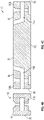
- the base 72 includes a portion 82 located vertically upward of the one or more channels 74.
- This portion 82 may be referred to herein as a cover and cooperates with the remainder of the base 72 to define at least a portion of the channel 74.
- the upper surface 84 of the cover 82 may be generally flush with the upper surface 76 of the remainder of the base 72.
- the base 72 may include a first cover 82a disposed upwardly adjacent the first channel 74a and a second cover 82b disposed upwardly adjacent the second channel 74b. As best shown in FIGS.
- the one or more covers 82a, 82b may be movable relative to the remainder of the base 72, or in some embodiments removable from the remainder of the base 72, to provide access to a corresponding channel 74a, 74b.
- the one or more covers 82a, 82b may be affixed to or integrally formed with the base 72, as shown in FIG. 6 .
- the base 72 need not include a cover 82 arranged vertically above the channel 74. In such embodiments, an upper surface of the channel 74 is not defined.
- the mounting assembly 70 additionally includes one or more flexible connectors or straps 86 configured to wrap at least partially about the circumference of the electrical harness 60 to secure the electrical harness 60 to the base 72.
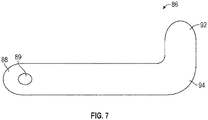
- An example of a flexible connector 86 is illustrated in more detail in FIG. 7 .
- the flexible connector 86 shown includes a first end 88 receivable within a corresponding channel formed in the base 72.
- a mounting hole 89 may be formed in the flexible connector 86 near the first end 88 such that when the first end 88 is installed within a corresponding channel 74 of the base 72, a fastener 90 may extend through the base 72 and the mounting hole 89 to couple the flexible connector 86 to the base 72.
- a protrusion 92 may extend from second end 94 of the flexible connector 86 at an angle, such as perpendicular for example, to the body of the flexible connector 86.
- the flexible connector 86 may be formed from any suitable non-rigid material.
- the flexible connector 86 may be formed from PEEK, TEFZEL, Teflon, Metal, or any other suitable material that meets the engine requirements at a given location.
- the flexible connector 86 may be formed form an encapsulated material.
- the assembly 70 includes a first flexible connector 86a associated with the first channel 74a and a second flexible connector 86b associated with the second channel 74b.
- first end 88a of the first flexible connector 86a is arranged within the first channel 74a and secured to the base 72 by a first fastener 90 and a first end 88b of the second flexible connector 86b is arranged within the second channel 74b and secured to the base 72 by a second fastener 90.
- a fastener such as a screw or bolt is shown, it should be understood that any suitable connector or fastening mechanism may be used to retain the first ends 88a, 88b of the flexible connector 86a, 86b relative to the base 72.
- the free second end 94a, 94b of the first flexible connector 86a and the second flexible connector 86b are positionable about an exterior surface of the electrical harness 60.
- the first flexible connector 86a and the second flexible connector 86b extend at an angle to the axis of the harness 60.
- the straps 86a, 86b are elongated such that the second ends 94a, 94b of the flexible connectors 86a, 86b are configured to overlap one another about the body of the electrical harness 60.
- the straps 86a, 86b may be configured to affix or couple to one another, as shown in FIG. 5 , such as via Velcro, a hook and loop fastening system, or any other suitable connection mechanism.
- each flexible connector 86a, 86b allows a user to easily maneuver and apply a desired force to the flexible connector 86a, 86b to secure the harness 60 to the module assembly70.
- each flexible connector 86a, 86b may be configured to couple to an opposite side of the base 72, such that the first end 88a, 88b of each flexible connector 86a, 86b is connected to the base 72 adjacent a first side of the electrical harness 60 and a second end 92a, 92b of the flexible connector 86a, 86b is coupled to the base 72 adjacent a second, opposite side of the electrical harness 60.
- any suitable connection mechanism (not shown) may used to secure the free second end of each flexible connector 86 to the base 72.
- the mounting assembly 70 includes a single flexible connector 86.
- the flexible connector 86 may, but need not include one or more mounting holes 89 and a protrusion 92 located at either end 88, 94 thereof.
- a portion of the flexible connector 86 may wrap about a lower surface 96 of the base 72.
- the single strap 86 may be received within a channel or groove (not shown) formed in the lower surface 96 so as not to interfere with the connection between the base 72 and the another component 98.
- the first end 88 of the strap 86 may extend through the first channel 74a and the second end 92 of the strap 86 may extend through the second channel 74b to wrap about the electrical harness 60.
- the first and second end 88, 94 of the flexible connector 86 couple to a portion of the base 72.
- a first end 88 of the single flexible connector 86 may be affixed to a portion of the base 72, such as within the first channel 74a for example.
- a free, second end 94 of the flexible connector 86 is configured to wrap about the electrical harness 60 before being affixed or coupled to the base 72, such as within the second channel 74b for example.
- a position of one or both of the first end 88 and the second end 94 of the flexible connector 86 is movable relative to the base 72 to control the pressure applied by the flexible connector 86 to the electrical harness 60.
- connection between the at least one flexible connector 86 and the base 72 and/or the connection between the straps 86 may be adjustable such that the mounting assembly 70 is suitable for use with a variety of electrical harnesses of different sizes.
- the mounting assembly 70 as illustrated and described herein is suitable for use an electrical harness 60 having various configurations of size and shape. Further, because the strap 86 is formed from a fabric or plastic material, rather than a metal, potential chafing between the harness 60 and the mounting assembly 70 is eliminated. Further, in embodiments where several mounting assemblies 70 are used to secure an electrical harness at various locations about an engine, the plurality of mounting assemblies 70 may be substantially identical, or may be different. For example, one or more components of the mounting assembly 70 may be formed from different materials depending on the position of the mounting assembly 70 relative to the engine 20.
Landscapes
- Engineering & Computer Science (AREA)
- General Engineering & Computer Science (AREA)
- Mechanical Engineering (AREA)
- Architecture (AREA)
- Civil Engineering (AREA)
- Structural Engineering (AREA)
- Structures Of Non-Positive Displacement Pumps (AREA)
- Installation Of Indoor Wiring (AREA)
Claims (15)
- Montageanordnung (70) zum Einschränken der Bewegung eines elektrischen Kabelbaums (60) eines Gasturbinentriebwerks (20), umfassend:eine Basis (72);einen ersten Kanal (74a), der in der Basis ausgebildet ist und sich zwischen einer ersten Oberfläche (76) und einer zweiten Oberfläche (78) der Basis erstreckt;einen zweiten Kanal (74b), der in der Basis ausgebildet ist und sich zwischen der ersten Oberfläche (76) und einer dritten Oberfläche (80) der Basis erstreckt, wobei die zweite Oberfläche und die dritte Oberfläche unterschiedlich sind; undmindestens einen flexiblen Verbinder (86), der in dem ersten Kanal und dem zweiten Kanal aufgenommen werden kann, wobei sich mindestens ein Teil des mindestens einen flexiblen Verbinders um den elektrischen Kabelbaum erstreckt, um den elektrischen Kabelbaum mit der Basis zu koppeln,dadurch gekennzeichnet, dass ein erstes Ende (88; 88a) des mindestens einen flexiblen Verbinders an der Basis innerhalb des ersten Kanals durch ein erstes Befestigungselement (90) befestigt ist und ein zweites Ende (94; 88b) des mindestens einen flexiblen Verbinders an der Basis innerhalb des zweiten Kanals durch ein zweites Befestigungselement (90) befestigt ist.
- Montageanordnung nach Anspruch 1, wobei der erste Kanal (74a) an eine erste Seite der Basis (72) angrenzt und der zweite Kanal (74b) angrenzend an eine zweite Seite der Basis positioniert ist.
- Montageanordnung nach Anspruch 1 oder 2, wobei sich der erste Kanal (74a) von einer oberen Oberfläche (76) der Basis (72) zu einer ersten Seitenoberfläche (78) der Basis erstreckt und der zweite Kanal (74b) von der oberen Oberfläche der Basis zu einer zweiten Seitenoberfläche (80) der Basis verläuft.
- Montageanordnung nach Anspruch 3, wobei die erste Seitenoberfläche gegenüber der zweiten Seitenoberfläche angeordnet ist.
- Montageanordnung nach Anspruch 1, wobei der mindestens eine flexible Verbinder (86) einen einzelnen flexiblen Verbinder enthält, wobei das erste Ende (88) des einzelnen flexiblen Verbinders innerhalb des ersten Kanals (74a) befestigt ist und das zweite Ende (94) des einzelnen flexiblen Verbinders innerhalb des zweiten Kanals (74b) befestigt ist.
- Montageanordnung nach Anspruch 1, wobei der mindestens eine flexible Verbinder einen ersten flexiblen Verbinder (86a) und einen zweiten flexiblen Verbinder (86b) aufweist, wobei ein erstes Ende (88a) des ersten flexiblen Verbinders in dem ersten Kanal (74a) befestigt ist und ein erstes Ende (88b) des zweiten flexiblen Verbinders in dem zweiten Kanal (74b) befestigt ist.
- Montageanordnung nach Anspruch 6, wobei ein zweites Ende (94a) des ersten flexiblen Verbinders mit einem zweiten Ende (94b) des zweiten flexiblen Verbinders koppelbar ist, um den elektrischen Kabelbaum (60) mit der Basis (72) zu koppeln; vorzugsweise
wobei das zweite Ende des ersten flexiblen Verbinders mit dem zweiten Ende des zweiten flexiblen Verbinders über eine hakenund schlaufenartige Befestigung koppelbar ist. - Montageanordnung nach Anspruch 6, wobei eine Lasche (92a, 92b) an einem zweiten Ende (94a, 94b) von mindestens einem des ersten flexiblen Verbinders (86a) und des zweiten flexiblen Verbinders (86b) ausgebildet ist.
- Montageanordnung nach einem der vorhergehenden Ansprüche, wobei eine Kraft, die von dem mindestens einen flexiblen Verbinder (86) auf den elektrischen Kabelbaum (60) ausgeübt wird, verstellbar ist.
- Montageanordnung nach einem der vorhergehenden Ansprüche, wobei der mindestens eine flexible Verbinder (86) ein Montageloch (89) umfasst, das in dem flexiblen Verbinder (86) in der Nähe des ersten Endes (89) ausgebildet ist, um das erste Befestigungselement (90) aufzunehmen; und wobei sich ein Vorsprung (92) von dem zweiten Ende (94) des flexiblen Verbinders (86) in einem senkrechten Winkel zu dem Körper des flexiblen Verbinders (86) erstreckt.
- Gasturbinentriebwerk (20), umfassend:eine Montageoberfläche;einen elektrischen Kabelbaum (60); unddie Montageanordnung nach einem der vorhergehenden Ansprüche, wobei die Basis (72) mit der Montageoberfläche verbunden ist.
- Gasturbinentriebwerk nach Anspruch 11, wobei das Triebwerk (20) ferner ein Gehäuse umfasst und die Montageoberfläche eine Außenoberfläche des Gehäuses ist.
- Gasturbinentriebwerk nach Anspruch 11 oder 12, wobei das Triebwerk (20) ein Flugzeugtriebwerk ist.
- Verfahren zum Einschränken der Bewegung eines elektrischen Kabelbaums (60) relativ zu einem Gasturbinentriebwerk (20), umfassend:Positionieren des elektrischen Kabelbaums in Kontakt mit einer Basis (72) einer Montageanordnung (70);Umwickeln des elektrischen Kabelbaums mit mindestens einem flexiblen Verbinder (86), wobei sich der mindestens eine flexible Verbinder durch einen ersten Kanal (74a) und einen zweiten Kanal (74b) erstreckt, die in der Basis ausgebildet sind, wobei der erste Kanal zwischen einer ersten Oberfläche (76) und einer zweiten Oberfläche (78) der Basis ausgebildet ist und der zweite Kanal zwischen der ersten Oberfläche (76) und einer dritten Oberfläche (80) der Basis ausgebildet ist, wobei die zweite Oberfläche und die dritte Oberfläche unterschiedlich sind; undEinschränken der Bewegung des mindestens einen flexiblen Verbinders relativ zur Basis,wobei das Verfahren dadurch gekennzeichnet ist, dass ein erstes Ende (88a) des mindestens einen flexiblen Verbinders an der Basis innerhalb des ersten Kanals durch ein erstes Befestigungselement (90) befestigt wird und ein zweites Ende (88b) des mindestens einen flexiblen Verbinders an der Basis innerhalb des zweiten Kanals durch ein zweites Befestigungselement (90) befestigt wird.
- Verfahren nach Anspruch 14, wobei der mindestens eine flexible Verbinder (86) ein Montageloch (89) umfasst, das in dem flexiblen Verbinder (86) in der Nähe des ersten Ende (89) ausgebildet ist, um das erste Befestigungselement (90) aufzunehmen; und wobei sich ein Vorsprung (92) von dem zweiten Ende (94) des flexiblen Verbinders (86) in einem senkrechten Winkel zu dem Körper des flexiblen Verbinders (86) erstreckt.
Applications Claiming Priority (1)
| Application Number | Priority Date | Filing Date | Title |
|---|---|---|---|
| US16/036,628 US10690267B2 (en) | 2018-07-16 | 2018-07-16 | Adjustable holding assembly |
Publications (2)
| Publication Number | Publication Date |
|---|---|
| EP3597487A1 EP3597487A1 (de) | 2020-01-22 |
| EP3597487B1 true EP3597487B1 (de) | 2022-05-25 |
Family
ID=67297051
Family Applications (1)
| Application Number | Title | Priority Date | Filing Date |
|---|---|---|---|
| EP19186294.5A Active EP3597487B1 (de) | 2018-07-16 | 2019-07-15 | Verstellbare halteanordnung |
Country Status (2)
| Country | Link |
|---|---|
| US (1) | US10690267B2 (de) |
| EP (1) | EP3597487B1 (de) |
Families Citing this family (6)
| Publication number | Priority date | Publication date | Assignee | Title |
|---|---|---|---|---|
| US10690267B2 (en) * | 2018-07-16 | 2020-06-23 | Raytheon Technologies Corporation | Adjustable holding assembly |
| US11427346B2 (en) * | 2018-09-28 | 2022-08-30 | Gulfstream Aerospace Corporation | Cable retainer apparatus and method for retaining a cable |
| US10907750B2 (en) * | 2019-04-29 | 2021-02-02 | Aptiv Technologies Limited | Modular retainer assembly |
| FR3122694B1 (fr) * | 2021-05-07 | 2024-03-29 | Safran Aircraft Engines | Turboréacteur muni d’un ensemble de fixation disposé sur un carter de soufflante |
| US12300407B2 (en) * | 2022-12-22 | 2025-05-13 | The Boeing Company | Connector to attach wiring to a housing |
| US20250129871A1 (en) * | 2023-10-24 | 2025-04-24 | Rtx Corporation | Damped fluid line for aircraft engine |
Family Cites Families (24)
| Publication number | Priority date | Publication date | Assignee | Title |
|---|---|---|---|---|
| US2409772A (en) | 1944-05-13 | 1946-10-22 | Adel Prec Products Corp | Adjustable harness clip |
| US3632071A (en) | 1969-11-24 | 1972-01-04 | Panduit Tinley Park | Mount for receiving and retaining a strap |
| US3971105A (en) | 1975-01-08 | 1976-07-27 | Panduit Corporation | Mount for flat objects such as flat cables |
| US4338707A (en) * | 1980-03-10 | 1982-07-13 | Ta Mfg. Corp. | Clamp |
| US4379537A (en) | 1981-08-10 | 1983-04-12 | Whipple Patent Management Corporation | Cable hanger |
| US4854015A (en) | 1988-06-10 | 1989-08-08 | The Boeing Company | Adjustable loop clamp |
| US5390883A (en) | 1994-04-11 | 1995-02-21 | Songhurst; Ronald W. | Releasable mounting binder for wires and cables |
| US5673889A (en) * | 1995-09-28 | 1997-10-07 | Devalcourt; Ricky D. | Wind surfing equipment holder |
| DE10010933C1 (de) | 2000-03-06 | 2001-08-16 | Daimler Chrysler Ag | Kabelhalter zur Befestigung von Kabeln in Fahrzeugstrukturen |
| AU2002245473A1 (en) | 2001-02-26 | 2002-09-12 | Federal-Mogul Powertrain, Inc | Rigidized protective sleeving |
| US6683258B1 (en) | 2003-04-03 | 2004-01-27 | 3M Innovative Properties Company | Cable restraining device |
| US7497718B2 (en) | 2006-11-08 | 2009-03-03 | International Truck Intellectual Property Company, Llc | Routing clip elements with a living hinge and interlocking closure |
| US8235345B2 (en) * | 2008-04-30 | 2012-08-07 | United Technologies Corp. | Gas turbine engine systems and related methods involving thermally isolated retention |
| GB201001002D0 (en) | 2010-01-22 | 2010-03-10 | Airbus Operations Ltd | A bracket for attaching an electrical cable to a vehicle |
| FR2965670B1 (fr) | 2010-09-30 | 2012-10-12 | Airbus Operations Sas | Dispositif de fixation de cables |
| FR2980549B1 (fr) | 2011-09-22 | 2014-11-28 | Aplix Sa | Collier d'attache pour des elements allonges |
| GB2497807B (en) * | 2011-12-22 | 2014-09-10 | Rolls Royce Plc | Electrical harness |
| FR2986829B1 (fr) * | 2012-02-09 | 2014-03-21 | Safran | Piece de support de turbomachine a structure hybride |
| US9534507B2 (en) | 2012-08-16 | 2017-01-03 | United Technologies Corporation | Harness support and mount |
| GB201301431D0 (en) * | 2013-01-28 | 2013-03-13 | Rolls Royce Plc | Component having a heat protection system |
| US20160121822A1 (en) | 2013-05-29 | 2016-05-05 | International Engine Intellectual Property Company ,LLC. | Harness clip and system for clipping wiring harness |
| DE102014101745A1 (de) | 2014-02-12 | 2015-08-13 | Hebotec Gmbh | Befestigungssystem |
| GB201409189D0 (en) * | 2014-05-23 | 2014-07-09 | Rolls Royce Plc | Fire resistant electrical panel |
| US10690267B2 (en) * | 2018-07-16 | 2020-06-23 | Raytheon Technologies Corporation | Adjustable holding assembly |
-
2018
- 2018-07-16 US US16/036,628 patent/US10690267B2/en active Active
-
2019
- 2019-07-15 EP EP19186294.5A patent/EP3597487B1/de active Active
Also Published As
| Publication number | Publication date |
|---|---|
| US20200018427A1 (en) | 2020-01-16 |
| EP3597487A1 (de) | 2020-01-22 |
| US10690267B2 (en) | 2020-06-23 |
Similar Documents
| Publication | Publication Date | Title |
|---|---|---|
| EP3597487B1 (de) | Verstellbare halteanordnung | |
| EP3879074B1 (de) | Heckkonus für eine gasturbine und montierter generator | |
| EP3054128B1 (de) | Getriebe für gasturbinenmotoren | |
| EP3032074A1 (de) | Zweiwellengetriebe für gasturbinenmotor | |
| US20130014389A1 (en) | Assembly fixture with wedge clamps for stator vane assembly | |
| US20200149475A1 (en) | Combined high pressure turbine case and turbine intermediate case | |
| EP3569839B1 (de) | Drehschutzvorrichtung für befestigungselemente | |
| EP3382279B1 (de) | Zwischenscheibe für brennkammeranordnung | |
| EP2930303A1 (de) | Gasturbinenkupplungsstapel | |
| EP4421299A2 (de) | Hybrider elektrischer motor und gondelsystem | |
| US9434031B2 (en) | Method and fixture for airfoil array assembly | |
| EP3418492B1 (de) | Zugankerrückhalteanordnung für turboluftstrahltriebwerk | |
| US11286797B2 (en) | Gas turbine engine stator vane base shape | |
| US20240076992A1 (en) | Stator retention of gas turbine engine | |
| EP3290660B1 (de) | Wärmedämmungsunterlegscheibe für eine verbundhalterung | |
| EP3054115A1 (de) | Verfahren zur begrenzung der bewegung eines halterings und halteringanordnung | |
| EP3034838B1 (de) | System und verfahren zur steuerung einer umgebungsbedingung eines elektronischen motorbauelements | |
| EP3431716A1 (de) | Verstellbare schaufelanordnung und zugehöriges fertigungsverfahren | |
| EP3611358B1 (de) | Entlüftungsventilbetätigungssystem | |
| US9482157B2 (en) | Bifurcation fire purge system for a gas turbine engine | |
| US9835091B2 (en) | Multiple piece shroud feedthru enclosure | |
| US10808559B2 (en) | Guide vane retention assembly for gas turbine engine | |
| US9297307B2 (en) | Power cable and connector arrangement for a gas turbine engine | |
| EP4715182A1 (de) | Kabelbaumblockklemme | |
| EP3054092B1 (de) | Kühlungsanordnung mit drallerzeugerrohr und verfahren zur montage |
Legal Events
| Date | Code | Title | Description |
|---|---|---|---|
| PUAI | Public reference made under article 153(3) epc to a published international application that has entered the european phase |
Free format text: ORIGINAL CODE: 0009012 |
|
| STAA | Information on the status of an ep patent application or granted ep patent |
Free format text: STATUS: THE APPLICATION HAS BEEN PUBLISHED |
|
| AK | Designated contracting states |
Kind code of ref document: A1 Designated state(s): AL AT BE BG CH CY CZ DE DK EE ES FI FR GB GR HR HU IE IS IT LI LT LU LV MC MK MT NL NO PL PT RO RS SE SI SK SM TR |
|
| AX | Request for extension of the european patent |
Extension state: BA ME |
|
| STAA | Information on the status of an ep patent application or granted ep patent |
Free format text: STATUS: REQUEST FOR EXAMINATION WAS MADE |
|
| 17P | Request for examination filed |
Effective date: 20200722 |
|
| RBV | Designated contracting states (corrected) |
Designated state(s): AL AT BE BG CH CY CZ DE DK EE ES FI FR GB GR HR HU IE IS IT LI LT LU LV MC MK MT NL NO PL PT RO RS SE SI SK SM TR |
|
| RAP1 | Party data changed (applicant data changed or rights of an application transferred) |
Owner name: RAYTHEON TECHNOLOGIES CORPORATION |
|
| GRAP | Despatch of communication of intention to grant a patent |
Free format text: ORIGINAL CODE: EPIDOSNIGR1 |
|
| STAA | Information on the status of an ep patent application or granted ep patent |
Free format text: STATUS: GRANT OF PATENT IS INTENDED |
|
| INTG | Intention to grant announced |
Effective date: 20211206 |
|
| GRAS | Grant fee paid |
Free format text: ORIGINAL CODE: EPIDOSNIGR3 |
|
| GRAA | (expected) grant |
Free format text: ORIGINAL CODE: 0009210 |
|
| STAA | Information on the status of an ep patent application or granted ep patent |
Free format text: STATUS: THE PATENT HAS BEEN GRANTED |
|
| AK | Designated contracting states |
Kind code of ref document: B1 Designated state(s): AL AT BE BG CH CY CZ DE DK EE ES FI FR GB GR HR HU IE IS IT LI LT LU LV MC MK MT NL NO PL PT RO RS SE SI SK SM TR |
|
| REG | Reference to a national code |
Ref country code: GB Ref legal event code: FG4D |
|
| REG | Reference to a national code |
Ref country code: CH Ref legal event code: EP |
|
| REG | Reference to a national code |
Ref country code: AT Ref legal event code: REF Ref document number: 1494146 Country of ref document: AT Kind code of ref document: T Effective date: 20220615 Ref country code: DE Ref legal event code: R096 Ref document number: 602019015192 Country of ref document: DE |
|
| REG | Reference to a national code |
Ref country code: IE Ref legal event code: FG4D |
|
| REG | Reference to a national code |
Ref country code: LT Ref legal event code: MG9D |
|
| REG | Reference to a national code |
Ref country code: NL Ref legal event code: MP Effective date: 20220525 |
|
| REG | Reference to a national code |
Ref country code: AT Ref legal event code: MK05 Ref document number: 1494146 Country of ref document: AT Kind code of ref document: T Effective date: 20220525 |
|
| PG25 | Lapsed in a contracting state [announced via postgrant information from national office to epo] |
Ref country code: SE Free format text: LAPSE BECAUSE OF FAILURE TO SUBMIT A TRANSLATION OF THE DESCRIPTION OR TO PAY THE FEE WITHIN THE PRESCRIBED TIME-LIMIT Effective date: 20220525 Ref country code: PT Free format text: LAPSE BECAUSE OF FAILURE TO SUBMIT A TRANSLATION OF THE DESCRIPTION OR TO PAY THE FEE WITHIN THE PRESCRIBED TIME-LIMIT Effective date: 20220926 Ref country code: NO Free format text: LAPSE BECAUSE OF FAILURE TO SUBMIT A TRANSLATION OF THE DESCRIPTION OR TO PAY THE FEE WITHIN THE PRESCRIBED TIME-LIMIT Effective date: 20220825 Ref country code: NL Free format text: LAPSE BECAUSE OF FAILURE TO SUBMIT A TRANSLATION OF THE DESCRIPTION OR TO PAY THE FEE WITHIN THE PRESCRIBED TIME-LIMIT Effective date: 20220525 Ref country code: LT Free format text: LAPSE BECAUSE OF FAILURE TO SUBMIT A TRANSLATION OF THE DESCRIPTION OR TO PAY THE FEE WITHIN THE PRESCRIBED TIME-LIMIT Effective date: 20220525 Ref country code: HR Free format text: LAPSE BECAUSE OF FAILURE TO SUBMIT A TRANSLATION OF THE DESCRIPTION OR TO PAY THE FEE WITHIN THE PRESCRIBED TIME-LIMIT Effective date: 20220525 Ref country code: GR Free format text: LAPSE BECAUSE OF FAILURE TO SUBMIT A TRANSLATION OF THE DESCRIPTION OR TO PAY THE FEE WITHIN THE PRESCRIBED TIME-LIMIT Effective date: 20220826 Ref country code: FI Free format text: LAPSE BECAUSE OF FAILURE TO SUBMIT A TRANSLATION OF THE DESCRIPTION OR TO PAY THE FEE WITHIN THE PRESCRIBED TIME-LIMIT Effective date: 20220525 Ref country code: ES Free format text: LAPSE BECAUSE OF FAILURE TO SUBMIT A TRANSLATION OF THE DESCRIPTION OR TO PAY THE FEE WITHIN THE PRESCRIBED TIME-LIMIT Effective date: 20220525 Ref country code: BG Free format text: LAPSE BECAUSE OF FAILURE TO SUBMIT A TRANSLATION OF THE DESCRIPTION OR TO PAY THE FEE WITHIN THE PRESCRIBED TIME-LIMIT Effective date: 20220825 Ref country code: AT Free format text: LAPSE BECAUSE OF FAILURE TO SUBMIT A TRANSLATION OF THE DESCRIPTION OR TO PAY THE FEE WITHIN THE PRESCRIBED TIME-LIMIT Effective date: 20220525 |
|
| PG25 | Lapsed in a contracting state [announced via postgrant information from national office to epo] |
Ref country code: RS Free format text: LAPSE BECAUSE OF FAILURE TO SUBMIT A TRANSLATION OF THE DESCRIPTION OR TO PAY THE FEE WITHIN THE PRESCRIBED TIME-LIMIT Effective date: 20220525 Ref country code: PL Free format text: LAPSE BECAUSE OF FAILURE TO SUBMIT A TRANSLATION OF THE DESCRIPTION OR TO PAY THE FEE WITHIN THE PRESCRIBED TIME-LIMIT Effective date: 20220525 Ref country code: LV Free format text: LAPSE BECAUSE OF FAILURE TO SUBMIT A TRANSLATION OF THE DESCRIPTION OR TO PAY THE FEE WITHIN THE PRESCRIBED TIME-LIMIT Effective date: 20220525 Ref country code: IS Free format text: LAPSE BECAUSE OF FAILURE TO SUBMIT A TRANSLATION OF THE DESCRIPTION OR TO PAY THE FEE WITHIN THE PRESCRIBED TIME-LIMIT Effective date: 20220925 |
|
| PG25 | Lapsed in a contracting state [announced via postgrant information from national office to epo] |
Ref country code: SM Free format text: LAPSE BECAUSE OF FAILURE TO SUBMIT A TRANSLATION OF THE DESCRIPTION OR TO PAY THE FEE WITHIN THE PRESCRIBED TIME-LIMIT Effective date: 20220525 Ref country code: SK Free format text: LAPSE BECAUSE OF FAILURE TO SUBMIT A TRANSLATION OF THE DESCRIPTION OR TO PAY THE FEE WITHIN THE PRESCRIBED TIME-LIMIT Effective date: 20220525 Ref country code: RO Free format text: LAPSE BECAUSE OF FAILURE TO SUBMIT A TRANSLATION OF THE DESCRIPTION OR TO PAY THE FEE WITHIN THE PRESCRIBED TIME-LIMIT Effective date: 20220525 Ref country code: EE Free format text: LAPSE BECAUSE OF FAILURE TO SUBMIT A TRANSLATION OF THE DESCRIPTION OR TO PAY THE FEE WITHIN THE PRESCRIBED TIME-LIMIT Effective date: 20220525 Ref country code: DK Free format text: LAPSE BECAUSE OF FAILURE TO SUBMIT A TRANSLATION OF THE DESCRIPTION OR TO PAY THE FEE WITHIN THE PRESCRIBED TIME-LIMIT Effective date: 20220525 Ref country code: CZ Free format text: LAPSE BECAUSE OF FAILURE TO SUBMIT A TRANSLATION OF THE DESCRIPTION OR TO PAY THE FEE WITHIN THE PRESCRIBED TIME-LIMIT Effective date: 20220525 |
|
| PG25 | Lapsed in a contracting state [announced via postgrant information from national office to epo] |
Ref country code: MC Free format text: LAPSE BECAUSE OF FAILURE TO SUBMIT A TRANSLATION OF THE DESCRIPTION OR TO PAY THE FEE WITHIN THE PRESCRIBED TIME-LIMIT Effective date: 20220525 |
|
| REG | Reference to a national code |
Ref country code: DE Ref legal event code: R097 Ref document number: 602019015192 Country of ref document: DE Ref country code: CH Ref legal event code: PL |
|
| REG | Reference to a national code |
Ref country code: BE Ref legal event code: MM Effective date: 20220731 |
|
| PG25 | Lapsed in a contracting state [announced via postgrant information from national office to epo] |
Ref country code: AL Free format text: LAPSE BECAUSE OF FAILURE TO SUBMIT A TRANSLATION OF THE DESCRIPTION OR TO PAY THE FEE WITHIN THE PRESCRIBED TIME-LIMIT Effective date: 20220525 |
|
| PLBE | No opposition filed within time limit |
Free format text: ORIGINAL CODE: 0009261 |
|
| STAA | Information on the status of an ep patent application or granted ep patent |
Free format text: STATUS: NO OPPOSITION FILED WITHIN TIME LIMIT |
|
| PG25 | Lapsed in a contracting state [announced via postgrant information from national office to epo] |
Ref country code: LU Free format text: LAPSE BECAUSE OF NON-PAYMENT OF DUE FEES Effective date: 20220715 Ref country code: LI Free format text: LAPSE BECAUSE OF NON-PAYMENT OF DUE FEES Effective date: 20220731 Ref country code: CH Free format text: LAPSE BECAUSE OF NON-PAYMENT OF DUE FEES Effective date: 20220731 |
|
| 26N | No opposition filed |
Effective date: 20230228 |
|
| PG25 | Lapsed in a contracting state [announced via postgrant information from national office to epo] |
Ref country code: SI Free format text: LAPSE BECAUSE OF FAILURE TO SUBMIT A TRANSLATION OF THE DESCRIPTION OR TO PAY THE FEE WITHIN THE PRESCRIBED TIME-LIMIT Effective date: 20220525 Ref country code: BE Free format text: LAPSE BECAUSE OF NON-PAYMENT OF DUE FEES Effective date: 20220731 |
|
| P01 | Opt-out of the competence of the unified patent court (upc) registered |
Effective date: 20230521 |
|
| PG25 | Lapsed in a contracting state [announced via postgrant information from national office to epo] |
Ref country code: IE Free format text: LAPSE BECAUSE OF NON-PAYMENT OF DUE FEES Effective date: 20220715 |
|
| PG25 | Lapsed in a contracting state [announced via postgrant information from national office to epo] |
Ref country code: IT Free format text: LAPSE BECAUSE OF FAILURE TO SUBMIT A TRANSLATION OF THE DESCRIPTION OR TO PAY THE FEE WITHIN THE PRESCRIBED TIME-LIMIT Effective date: 20220525 |
|
| PG25 | Lapsed in a contracting state [announced via postgrant information from national office to epo] |
Ref country code: HU Free format text: LAPSE BECAUSE OF FAILURE TO SUBMIT A TRANSLATION OF THE DESCRIPTION OR TO PAY THE FEE WITHIN THE PRESCRIBED TIME-LIMIT; INVALID AB INITIO Effective date: 20190715 |
|
| PG25 | Lapsed in a contracting state [announced via postgrant information from national office to epo] |
Ref country code: MK Free format text: LAPSE BECAUSE OF FAILURE TO SUBMIT A TRANSLATION OF THE DESCRIPTION OR TO PAY THE FEE WITHIN THE PRESCRIBED TIME-LIMIT Effective date: 20220525 Ref country code: CY Free format text: LAPSE BECAUSE OF FAILURE TO SUBMIT A TRANSLATION OF THE DESCRIPTION OR TO PAY THE FEE WITHIN THE PRESCRIBED TIME-LIMIT Effective date: 20220525 |
|
| PG25 | Lapsed in a contracting state [announced via postgrant information from national office to epo] |
Ref country code: TR Free format text: LAPSE BECAUSE OF FAILURE TO SUBMIT A TRANSLATION OF THE DESCRIPTION OR TO PAY THE FEE WITHIN THE PRESCRIBED TIME-LIMIT Effective date: 20220525 |
|
| PG25 | Lapsed in a contracting state [announced via postgrant information from national office to epo] |
Ref country code: MT Free format text: LAPSE BECAUSE OF FAILURE TO SUBMIT A TRANSLATION OF THE DESCRIPTION OR TO PAY THE FEE WITHIN THE PRESCRIBED TIME-LIMIT Effective date: 20220525 |
|
| PG25 | Lapsed in a contracting state [announced via postgrant information from national office to epo] |
Ref country code: BG Free format text: LAPSE BECAUSE OF FAILURE TO SUBMIT A TRANSLATION OF THE DESCRIPTION OR TO PAY THE FEE WITHIN THE PRESCRIBED TIME-LIMIT Effective date: 20220525 |
|
| PG25 | Lapsed in a contracting state [announced via postgrant information from national office to epo] |
Ref country code: BG Free format text: LAPSE BECAUSE OF FAILURE TO SUBMIT A TRANSLATION OF THE DESCRIPTION OR TO PAY THE FEE WITHIN THE PRESCRIBED TIME-LIMIT Effective date: 20220525 |
|
| PGFP | Annual fee paid to national office [announced via postgrant information from national office to epo] |
Ref country code: GB Payment date: 20250619 Year of fee payment: 7 |
|
| PGFP | Annual fee paid to national office [announced via postgrant information from national office to epo] |
Ref country code: FR Payment date: 20250620 Year of fee payment: 7 |
|
| REG | Reference to a national code |
Ref country code: DE Ref legal event code: R081 Ref document number: 602019015192 Country of ref document: DE Owner name: RTX CORPORATION (N.D.GES.D. STAATES DELAWARE),, US Free format text: FORMER OWNER: RAYTHEON TECHNOLOGIES CORPORATION, FARMINGTON, CT, US |
|
| PGFP | Annual fee paid to national office [announced via postgrant information from national office to epo] |
Ref country code: DE Payment date: 20250620 Year of fee payment: 7 |