EP3597481B1 - Befestigungssystem zum halten von gurten - Google Patents
Befestigungssystem zum halten von gurten Download PDFInfo
- Publication number
- EP3597481B1 EP3597481B1 EP19000259.2A EP19000259A EP3597481B1 EP 3597481 B1 EP3597481 B1 EP 3597481B1 EP 19000259 A EP19000259 A EP 19000259A EP 3597481 B1 EP3597481 B1 EP 3597481B1
- Authority
- EP
- European Patent Office
- Prior art keywords
- fastening
- fastening system
- girder
- operating position
- previous
- Prior art date
- Legal status (The legal status is an assumption and is not a legal conclusion. Google has not performed a legal analysis and makes no representation as to the accuracy of the status listed.)
- Active
Links
Images






Classifications
-
- B—PERFORMING OPERATIONS; TRANSPORTING
- B60—VEHICLES IN GENERAL
- B60P—VEHICLES ADAPTED FOR LOAD TRANSPORTATION OR TO TRANSPORT, TO CARRY, OR TO COMPRISE SPECIAL LOADS OR OBJECTS
- B60P3/00—Vehicles adapted to transport, to carry or to comprise special loads or objects
- B60P3/06—Vehicles adapted to transport, to carry or to comprise special loads or objects for carrying vehicles
- B60P3/07—Vehicles adapted to transport, to carry or to comprise special loads or objects for carrying vehicles for carrying road vehicles
- B60P3/073—Vehicle retainers
- B60P3/079—Tie-down retainers
Definitions
- the present invention refers to a fastening system for holding belts aimed in particular to be used for transporting motor vehicles on loading flatbeds.
- EP2998158 instead discloses a holed sheet for semi-trailers, trailers and/or railcars, for transporting vehicles, equipped with a fastening counter-support device, made as a longitudinal rail and placed below the loading surfaces of the flatbed, such device being equipped with dampening means, made as fastening rods connected to such rail, to absorb the forces acting at a right angle with respect to the loading surfaces and capable of being generated through fastening means, such as fastening hooks and/or belts connected to such dampening means.
- dampening means made as fastening rods connected to such rail
- object of the present invention is solving the above prior art problems, by providing a fastening system for holding belts, aimed in particular to be used for transporting motor vehicles on loading flatbeds, comprising fastening elements which can be festened directly to the oval holes of a sheet and allow not transmitting on spots the tension directly to such oval holes, but transmitting such tension in order to avoid the concentration of tension in the edges of the oval holes, which can bring about localized deformations.
- Another object of the present invention is providing a fastening system for holding belts, aimed in particular to be used for transporting motor vehicles on loading flatbeds, further comprising suitable girders to be arranged below any already existing flatbed and which allow not only to avoid a tension concentratione in the edges of the oval holes which can bring about localized deformations, but also to transmit the tension directly to structural parts thereof.
- the fastening system 1 for holding belts 3 aimed in particular to be used for transporting motor vehicles on at least one loading flatbed 5 comprising one or more through-openings 51 (typically the oval holes of known flatbeds), comprises at least one fastening element 10 interposed between at least one belt 3 and such flatbed 5, the fastening element 10 being equipped with at least one fastening portion 11 and with at least one connection or transmission portion 13 of the belt 3, the fastening element 1 being able to pass from a first operating position in which the fastening portion 11 is passing through at least one opening 51 to a second operating position in which the fastening portion 11 is prevented from going out from the opening 51, and vice versa.
- the fastening element 10 comprises at least one stem 15, preferably with round section, joining the fastening portion 11 and the connecting portion 13, the connecting portion 13 being equipped with at least one hook or eyelet 17 designed to allo the connection with the belt as a direct connection of a terminal portion of the belt 3 itself (such as, for example, in the operating configuration shown in box A of Figure 1 ) or by interposing at least one tensioning device 7 (such as, for example, in the operating configuration shown in box B of Figure 1 ), or the transmission of an intermediate portion of the belt 3 (such as, for example, in the operating configuration shown in box C of Figure 1 ), for example also by interposing at least one suitable connecting means, like a shackle 19 with screw-type transverse pin.
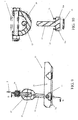
- the fastening portion 11 is shaped substantially as a reverse "T" and comprises two opposite appendixes 11a, going out axially, along a O-O axis, from the end of the stem 15 in a substantially perpendicular position with respect to a longitudinal axis V-V of the stem 15 itself.
- the fastening system 1 can further comprise at least one connecting girder 30, preferably also having structural functions, to be arranged below any flatbed 5 (of the type known in the art), the girder 30 being equipped with at least one longitudinal seat 31, preferably placed next to at least one through-opening 51 of the flatbed 5.
- the fastening element 10 can then pass from the first operating position in which the fastening portion 11 is passing through the opening 51 and is unconstrained from the seat 31, to a second operating position in which the fastening portion 11 engages at least one seat 31 and is prevented from going out from the opening 51, and vice versa.
- the girder 30 comprises at least two parallel and facing, longitudinal surfaces 33, each of the surfaces 33 being equipped with at least one seat 31 adapted to be engaged by a respective appendix 11a of the fastening portion 11 when the fastening element 10 is in the second operating position: in particular, the section of the appendixes 11a is preferably circular to allow their correct abutment in the seat 31 according to different angles.
- the girder 30 has a "U"-shaped section, composed of the surfaces 33 and at least one connecting base 35 of the surfaces 33.
- the suitable dimensioning of the diameter of the appendixes 11a allows distributing the pressure induced by the belt 3 in order to avoid dangerous tension concentrations, a localized plasticization, deformations and burrs on the edge, as happened with the classic prior art hook.
- the seats 31 for the appendixes 11a of the fastening portion 11 can be directly obtained in the surfaces 33 of the girder 30, typically in through-sheet.
- the fastening element 10 as described above can then be inserted, in its first operating position, through an opening 51 (oval hole) of any prior art flatbed 5, and then taken to its second operating position to prevent it from going out and allow a fastening to the flatbed 5 of the related belt 3.
- the fastening element 10 when it is in its first operating position, it can be made pass through the opening of the flatbed. Afterwards, it is enough to rotate the fastening element by about 90° around axis V-V to take the appendixes 11a to engage from below the opening 51 and prevent it from going out, for example under the traction action of the belt connected thereto.
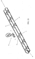
- FIG. 11 to 14 some steps of laying a fastening element 10 of the fastening system 1 according to the present invention are shown, also comprising the girder 30 and through at least one opening (oval hole, not shown) of a loading flatbed 5.
- the fastening element 10 is in its first operating position, namely it is able to pass through an opening (not shown) of the flatbed and has the fastening portion unconstrained from the seats 31 of the girder 30.
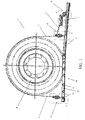
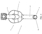
- Figures 1 and 2 show, as an example, the fastening system according to the present invention applied to a preferred use mode for fastening a wheel R of a vehicle to the flatbed 5 through a belt 3 partially wound around the tire tread of the wheel R and equipped with three fastening points A, B, C to the girder 30 by interposing respective fastening elements 10 inserted through the openings 51 of the flatbed 5, and possibly put under traction through at least one tensioning device 7 (usually a ratchet).
- a tensioning device 7 usually a ratchet
Landscapes
- Engineering & Computer Science (AREA)
- Health & Medical Sciences (AREA)
- Public Health (AREA)
- Transportation (AREA)
- Mechanical Engineering (AREA)
- Connection Of Plates (AREA)
- Load-Engaging Elements For Cranes (AREA)
- Piles And Underground Anchors (AREA)
- Joining Of Building Structures In Genera (AREA)
Claims (9)
- Verankerungssystem (1) für Rückhaltegurte (3), das zum Transport von Kraftfahrzeugen auf Ladeplattformen (5) vorgesehen ist, die eine oder mehrere Durchgangsöffnungen (51) umfassen, wobei das Verankerungssystem (1) mindestens eine Verankerung umfasst Element (10), das zwischen mindestens einem der Riemen (3) und der Plattform (5) angeordnet ist, wobei das Verankerungselement (1) mit mindestens einem Hakenabschnitt (11) und mindestens einem Abschnitt (13) zur Verbindung oder ausgestattet ist Rückführung eines Riemens (3), wobei das Verankerungselement (10) von einer ersten Betriebsposition, in der der Kupplungsabschnitt (11) durch mindestens eine der Öffnungen (51) verläuft, zu einer zweiten Betriebsposition gelangen kann, in der Es wird verhindert, dass der Hakenabschnitt (11) aus der Öffnung (51) herauskommt, und umgekehrt, wobei das Verankerungssystem (1) mindestens ein Verbindungslängselement (30) umfasst, das unter der Plattform (5) angeordnet sein soll, wobei der Holm (30) mit Alme ausgestattet sein einen Längssitz (31), wobei das Verankerungselement (10) von der ersten Betriebsposition, in der der Kupplungsabschnitt (11) durch die Öffnung (51) verläuft, passieren kann und von dem Sitz (31) zum zweiten Betrieb freigegeben wird Position, in der der Hakenabschnitt (11) in mindestens einen der Sitze (31) eingreift und daran gehindert ist, aus der Öffnung (51) herauszukommen, und umgekehrt;
in dem der Kopplungsabschnitt (11) im wesentlichen die Form eines umgekehrten "T" hat,
gekennzeichnet durch die Tatsache, dass der Kopplungsabschnitt zwei gegenüberliegende Anhänge (11a) umfasst, die axial aus einem Ende des Schafts (15) in einer im Wesentlichen senkrechten Position in Bezug auf eine Längsachse des Schafts (15) und des Längselements (30) herausragen) umfasst mindestens zwei Längsflächen (33), die parallel und einander zugewandt sind, wobei jede der Flächen (33) mit mindestens einem der Sitze (31) ausgestattet ist, die von einem jeweiligen der Anhänge (11a) eingerastet werden können, des Hakenabschnitts (11), wenn sich das Verankerungselement (10) in der zweiten Betriebsposition befindet. - Verankerungssystem (1) nach dem vorhergehenden Anspruch, dadurch gekennzeichnet, dass das Verankerungselement (10) mindestens einen Schaft (15) umfasst, der den Hakenabschnitt (11) und den Verbindungsabschnitt (13) verbindet.
- Verankerungssystem (1) nach einem der vorhergehenden Ansprüche, das dadurch gekennzeichnet ist, dass der Verbindungsabschnitt (13) mit mindestens einem Haken oder einer Öse (17) ausgestattet ist.
- Verankerungssystem (1) nach dem vorhergehenden Anspruch, gekennzeichnet durch die Tatsache, dass der Haken oder die Öse (17) durch Zwischenschalten von mindestens einem Verbindungsmittel mit dem Riemen verbunden ist.
- Verankerungssystem (1) nach dem vorhergehenden Anspruch, dadurch gekennzeichnet, dass das Verbindungsmittel mindestens ein Schäkel (19) mit einem Schraubenquerstift ist.
- Verankerungssystem (1) nach dem vorhergehenden Anspruch, dadurch gekennzeichnet, dass ein Abschnitt der Anhänge (11a) kreisförmig ist.
- Verankerungssystem (1) nach Anspruch 1, dadurch gekennzeichnet, dass das Längsträger (30) strukturelle Funktionen hat.
- Verankerungssystem (1) nach einem der vorhergehenden Ansprüche, gekennzeichnet dadurch, dass der Längssitz (31) in Übereinstimmung mit mindestens einer Durchgangsöffnung (51) der Plattform (5) positioniert ist.
- Verankerungssystem (1) nach einem der vorhergehenden Ansprüche, gekennzeichnet durch die Tatsache, dass das Längsträger (30) mit einem "U" - Abschnitt geformt ist, der aus den Oberflächen (33) und mindestens einer Basis (35) besteht, zum Verbinden der Flächen (33).
Applications Claiming Priority (1)
| Application Number | Priority Date | Filing Date | Title |
|---|---|---|---|
| IT102018000007338A IT201800007338A1 (it) | 2018-07-19 | 2018-07-19 | Sistema di ancoraggio per cinghie di ritenuta. |
Publications (2)
| Publication Number | Publication Date |
|---|---|
| EP3597481A1 EP3597481A1 (de) | 2020-01-22 |
| EP3597481B1 true EP3597481B1 (de) | 2021-04-07 |
Family
ID=63834527
Family Applications (1)
| Application Number | Title | Priority Date | Filing Date |
|---|---|---|---|
| EP19000259.2A Active EP3597481B1 (de) | 2018-07-19 | 2019-05-28 | Befestigungssystem zum halten von gurten |
Country Status (3)
| Country | Link |
|---|---|
| EP (1) | EP3597481B1 (de) |
| IT (1) | IT201800007338A1 (de) |
| LT (1) | LT3597481T (de) |
Family Cites Families (3)
| Publication number | Priority date | Publication date | Assignee | Title |
|---|---|---|---|---|
| US3853347A (en) * | 1972-08-03 | 1974-12-10 | Bethlehem Fabrications Inc | Vehicle for carrying other vehicles and its tie-down setup |
| US4960353A (en) * | 1989-06-06 | 1990-10-02 | Thorfam Corp. | Wheel anchoring harness for motor vehicle transportation systems |
| DE502014004541C5 (de) * | 2014-12-01 | 2021-12-30 | Fms Fahrzeugbau Gmbh | Lochblechfahrbahn |
-
2018
- 2018-07-19 IT IT102018000007338A patent/IT201800007338A1/it unknown
-
2019
- 2019-05-28 EP EP19000259.2A patent/EP3597481B1/de active Active
- 2019-05-28 LT LTEP19000259.2T patent/LT3597481T/lt unknown
Non-Patent Citations (1)
| Title |
|---|
| None * |
Also Published As
| Publication number | Publication date |
|---|---|
| EP3597481A1 (de) | 2020-01-22 |
| IT201800007338A1 (it) | 2018-10-19 |
| LT3597481T (lt) | 2021-07-12 |
Similar Documents
| Publication | Publication Date | Title |
|---|---|---|
| US5011347A (en) | Universal wheel restraining cleat and strap assembly for wheel chocks | |
| US4786223A (en) | Vehicle hold-down system | |
| US2688289A (en) | Cargo tie-down assembly | |
| EP2848468B1 (de) | System zur Sicherung eines Fahrzeugs beim Transport gegen Bewegung unter Kräften aus mehreren Richtungen | |
| US8662803B2 (en) | Wheel restraint system | |
| US4979856A (en) | Vehicle cantilever chock block apparatus for railroad car transport of vehicles | |
| US9884581B1 (en) | Adjustable lever load binder | |
| CN102099228A (zh) | 安全带锚定装置 | |
| US5593260A (en) | Apparatus for securing a vehicle to a trailer | |
| EP3597481B1 (de) | Befestigungssystem zum halten von gurten | |
| US4022134A (en) | Automobile tie down assembly | |
| US7458238B2 (en) | Load binder locking device | |
| US3215390A (en) | Tie-down device | |
| US20210323461A1 (en) | Variable strap location on wheel restraint system | |
| EP3323675B1 (de) | Befestigungssystem zum halten von gurten | |
| US20060021689A1 (en) | Non-return block for snow chains | |
| CA2889621C (en) | Connector anchor having multiple direction connectivity | |
| US3252189A (en) | Line tensioning apparatus | |
| US3348273A (en) | 3-way automobile tie-down hook | |
| US20140159448A1 (en) | Child seat safety strap | |
| US10668769B2 (en) | Anti-roll off assembly and system including same | |
| JPH0858325A (ja) | 車両用牽引フック装置 | |
| EP2923895B1 (de) | Gurtbeschlag | |
| JP3141485U (ja) | 貨物自動車用荷台防水カバー | |
| CN104603975B (zh) | 用于车辆中的电池的紧固系统 |
Legal Events
| Date | Code | Title | Description |
|---|---|---|---|
| PUAI | Public reference made under article 153(3) epc to a published international application that has entered the european phase |
Free format text: ORIGINAL CODE: 0009012 |
|
| STAA | Information on the status of an ep patent application or granted ep patent |
Free format text: STATUS: THE APPLICATION HAS BEEN PUBLISHED |
|
| AK | Designated contracting states |
Kind code of ref document: A1 Designated state(s): AL AT BE BG CH CY CZ DE DK EE ES FI FR GB GR HR HU IE IS IT LI LT LU LV MC MK MT NL NO PL PT RO RS SE SI SK SM TR |
|
| AX | Request for extension of the european patent |
Extension state: BA ME |
|
| STAA | Information on the status of an ep patent application or granted ep patent |
Free format text: STATUS: REQUEST FOR EXAMINATION WAS MADE |
|
| 17P | Request for examination filed |
Effective date: 20200629 |
|
| RBV | Designated contracting states (corrected) |
Designated state(s): AL AT BE BG CH CY CZ DE DK EE ES FI FR GB GR HR HU IE IS IT LI LT LU LV MC MK MT NL NO PL PT RO RS SE SI SK SM TR |
|
| GRAP | Despatch of communication of intention to grant a patent |
Free format text: ORIGINAL CODE: EPIDOSNIGR1 |
|
| STAA | Information on the status of an ep patent application or granted ep patent |
Free format text: STATUS: GRANT OF PATENT IS INTENDED |
|
| INTG | Intention to grant announced |
Effective date: 20210113 |
|
| GRAS | Grant fee paid |
Free format text: ORIGINAL CODE: EPIDOSNIGR3 |
|
| GRAA | (expected) grant |
Free format text: ORIGINAL CODE: 0009210 |
|
| STAA | Information on the status of an ep patent application or granted ep patent |
Free format text: STATUS: THE PATENT HAS BEEN GRANTED |
|
| AK | Designated contracting states |
Kind code of ref document: B1 Designated state(s): AL AT BE BG CH CY CZ DE DK EE ES FI FR GB GR HR HU IE IS IT LI LT LU LV MC MK MT NL NO PL PT RO RS SE SI SK SM TR |
|
| REG | Reference to a national code |
Ref country code: GB Ref legal event code: FG4D |
|
| REG | Reference to a national code |
Ref country code: AT Ref legal event code: REF Ref document number: 1379280 Country of ref document: AT Kind code of ref document: T Effective date: 20210415 Ref country code: CH Ref legal event code: EP |
|
| REG | Reference to a national code |
Ref country code: DE Ref legal event code: R096 Ref document number: 602019003624 Country of ref document: DE |
|
| REG | Reference to a national code |
Ref country code: IE Ref legal event code: FG4D |
|
| REG | Reference to a national code |
Ref country code: NL Ref legal event code: MP Effective date: 20210407 |
|
| PG25 | Lapsed in a contracting state [announced via postgrant information from national office to epo] |
Ref country code: NL Free format text: LAPSE BECAUSE OF FAILURE TO SUBMIT A TRANSLATION OF THE DESCRIPTION OR TO PAY THE FEE WITHIN THE PRESCRIBED TIME-LIMIT Effective date: 20210407 Ref country code: BG Free format text: LAPSE BECAUSE OF FAILURE TO SUBMIT A TRANSLATION OF THE DESCRIPTION OR TO PAY THE FEE WITHIN THE PRESCRIBED TIME-LIMIT Effective date: 20210707 Ref country code: FI Free format text: LAPSE BECAUSE OF FAILURE TO SUBMIT A TRANSLATION OF THE DESCRIPTION OR TO PAY THE FEE WITHIN THE PRESCRIBED TIME-LIMIT Effective date: 20210407 Ref country code: HR Free format text: LAPSE BECAUSE OF FAILURE TO SUBMIT A TRANSLATION OF THE DESCRIPTION OR TO PAY THE FEE WITHIN THE PRESCRIBED TIME-LIMIT Effective date: 20210407 |
|
| PG25 | Lapsed in a contracting state [announced via postgrant information from national office to epo] |
Ref country code: GR Free format text: LAPSE BECAUSE OF FAILURE TO SUBMIT A TRANSLATION OF THE DESCRIPTION OR TO PAY THE FEE WITHIN THE PRESCRIBED TIME-LIMIT Effective date: 20210708 Ref country code: IS Free format text: LAPSE BECAUSE OF FAILURE TO SUBMIT A TRANSLATION OF THE DESCRIPTION OR TO PAY THE FEE WITHIN THE PRESCRIBED TIME-LIMIT Effective date: 20210807 Ref country code: RS Free format text: LAPSE BECAUSE OF FAILURE TO SUBMIT A TRANSLATION OF THE DESCRIPTION OR TO PAY THE FEE WITHIN THE PRESCRIBED TIME-LIMIT Effective date: 20210407 Ref country code: SE Free format text: LAPSE BECAUSE OF FAILURE TO SUBMIT A TRANSLATION OF THE DESCRIPTION OR TO PAY THE FEE WITHIN THE PRESCRIBED TIME-LIMIT Effective date: 20210407 Ref country code: PT Free format text: LAPSE BECAUSE OF FAILURE TO SUBMIT A TRANSLATION OF THE DESCRIPTION OR TO PAY THE FEE WITHIN THE PRESCRIBED TIME-LIMIT Effective date: 20210809 Ref country code: LV Free format text: LAPSE BECAUSE OF FAILURE TO SUBMIT A TRANSLATION OF THE DESCRIPTION OR TO PAY THE FEE WITHIN THE PRESCRIBED TIME-LIMIT Effective date: 20210407 Ref country code: NO Free format text: LAPSE BECAUSE OF FAILURE TO SUBMIT A TRANSLATION OF THE DESCRIPTION OR TO PAY THE FEE WITHIN THE PRESCRIBED TIME-LIMIT Effective date: 20210707 Ref country code: PL Free format text: LAPSE BECAUSE OF FAILURE TO SUBMIT A TRANSLATION OF THE DESCRIPTION OR TO PAY THE FEE WITHIN THE PRESCRIBED TIME-LIMIT Effective date: 20210407 |
|
| REG | Reference to a national code |
Ref country code: DE Ref legal event code: R097 Ref document number: 602019003624 Country of ref document: DE |
|
| PG25 | Lapsed in a contracting state [announced via postgrant information from national office to epo] |
Ref country code: CZ Free format text: LAPSE BECAUSE OF FAILURE TO SUBMIT A TRANSLATION OF THE DESCRIPTION OR TO PAY THE FEE WITHIN THE PRESCRIBED TIME-LIMIT Effective date: 20210407 Ref country code: DK Free format text: LAPSE BECAUSE OF FAILURE TO SUBMIT A TRANSLATION OF THE DESCRIPTION OR TO PAY THE FEE WITHIN THE PRESCRIBED TIME-LIMIT Effective date: 20210407 Ref country code: LU Free format text: LAPSE BECAUSE OF NON-PAYMENT OF DUE FEES Effective date: 20210528 Ref country code: SM Free format text: LAPSE BECAUSE OF FAILURE TO SUBMIT A TRANSLATION OF THE DESCRIPTION OR TO PAY THE FEE WITHIN THE PRESCRIBED TIME-LIMIT Effective date: 20210407 Ref country code: MC Free format text: LAPSE BECAUSE OF FAILURE TO SUBMIT A TRANSLATION OF THE DESCRIPTION OR TO PAY THE FEE WITHIN THE PRESCRIBED TIME-LIMIT Effective date: 20210407 Ref country code: RO Free format text: LAPSE BECAUSE OF FAILURE TO SUBMIT A TRANSLATION OF THE DESCRIPTION OR TO PAY THE FEE WITHIN THE PRESCRIBED TIME-LIMIT Effective date: 20210407 Ref country code: EE Free format text: LAPSE BECAUSE OF FAILURE TO SUBMIT A TRANSLATION OF THE DESCRIPTION OR TO PAY THE FEE WITHIN THE PRESCRIBED TIME-LIMIT Effective date: 20210407 Ref country code: ES Free format text: LAPSE BECAUSE OF FAILURE TO SUBMIT A TRANSLATION OF THE DESCRIPTION OR TO PAY THE FEE WITHIN THE PRESCRIBED TIME-LIMIT Effective date: 20210407 Ref country code: SK Free format text: LAPSE BECAUSE OF FAILURE TO SUBMIT A TRANSLATION OF THE DESCRIPTION OR TO PAY THE FEE WITHIN THE PRESCRIBED TIME-LIMIT Effective date: 20210407 |
|
| REG | Reference to a national code |
Ref country code: BE Ref legal event code: MM Effective date: 20210531 |
|
| PLBE | No opposition filed within time limit |
Free format text: ORIGINAL CODE: 0009261 |
|
| STAA | Information on the status of an ep patent application or granted ep patent |
Free format text: STATUS: NO OPPOSITION FILED WITHIN TIME LIMIT |
|
| 26N | No opposition filed |
Effective date: 20220110 |
|
| PG25 | Lapsed in a contracting state [announced via postgrant information from national office to epo] |
Ref country code: IE Free format text: LAPSE BECAUSE OF NON-PAYMENT OF DUE FEES Effective date: 20210528 |
|
| PG25 | Lapsed in a contracting state [announced via postgrant information from national office to epo] |
Ref country code: IS Free format text: LAPSE BECAUSE OF FAILURE TO SUBMIT A TRANSLATION OF THE DESCRIPTION OR TO PAY THE FEE WITHIN THE PRESCRIBED TIME-LIMIT Effective date: 20210807 Ref country code: AL Free format text: LAPSE BECAUSE OF FAILURE TO SUBMIT A TRANSLATION OF THE DESCRIPTION OR TO PAY THE FEE WITHIN THE PRESCRIBED TIME-LIMIT Effective date: 20210407 |
|
| PG25 | Lapsed in a contracting state [announced via postgrant information from national office to epo] |
Ref country code: BE Free format text: LAPSE BECAUSE OF NON-PAYMENT OF DUE FEES Effective date: 20210531 |
|
| PGFP | Annual fee paid to national office [announced via postgrant information from national office to epo] |
Ref country code: IT Payment date: 20220531 Year of fee payment: 4 |
|
| REG | Reference to a national code |
Ref country code: CH Ref legal event code: PL |
|
| REG | Reference to a national code |
Ref country code: AT Ref legal event code: UEP Ref document number: 1379280 Country of ref document: AT Kind code of ref document: T Effective date: 20210407 |
|
| PG25 | Lapsed in a contracting state [announced via postgrant information from national office to epo] |
Ref country code: LI Free format text: LAPSE BECAUSE OF NON-PAYMENT OF DUE FEES Effective date: 20220531 Ref country code: CH Free format text: LAPSE BECAUSE OF NON-PAYMENT OF DUE FEES Effective date: 20220531 |
|
| PG25 | Lapsed in a contracting state [announced via postgrant information from national office to epo] |
Ref country code: CY Free format text: LAPSE BECAUSE OF FAILURE TO SUBMIT A TRANSLATION OF THE DESCRIPTION OR TO PAY THE FEE WITHIN THE PRESCRIBED TIME-LIMIT Effective date: 20210407 |
|
| PG25 | Lapsed in a contracting state [announced via postgrant information from national office to epo] |
Ref country code: HU Free format text: LAPSE BECAUSE OF FAILURE TO SUBMIT A TRANSLATION OF THE DESCRIPTION OR TO PAY THE FEE WITHIN THE PRESCRIBED TIME-LIMIT; INVALID AB INITIO Effective date: 20190528 |
|
| PGFP | Annual fee paid to national office [announced via postgrant information from national office to epo] |
Ref country code: LT Payment date: 20230518 Year of fee payment: 5 Ref country code: FR Payment date: 20230525 Year of fee payment: 5 Ref country code: DE Payment date: 20230530 Year of fee payment: 5 |
|
| PGFP | Annual fee paid to national office [announced via postgrant information from national office to epo] |
Ref country code: TR Payment date: 20230518 Year of fee payment: 5 |
|
| GBPC | Gb: european patent ceased through non-payment of renewal fee |
Effective date: 20230528 |
|
| PG25 | Lapsed in a contracting state [announced via postgrant information from national office to epo] |
Ref country code: MK Free format text: LAPSE BECAUSE OF FAILURE TO SUBMIT A TRANSLATION OF THE DESCRIPTION OR TO PAY THE FEE WITHIN THE PRESCRIBED TIME-LIMIT Effective date: 20210407 Ref country code: IT Free format text: LAPSE BECAUSE OF NON-PAYMENT OF DUE FEES Effective date: 20230528 Ref country code: GB Free format text: LAPSE BECAUSE OF NON-PAYMENT OF DUE FEES Effective date: 20230528 |
|
| PG25 | Lapsed in a contracting state [announced via postgrant information from national office to epo] |
Ref country code: MT Free format text: LAPSE BECAUSE OF FAILURE TO SUBMIT A TRANSLATION OF THE DESCRIPTION OR TO PAY THE FEE WITHIN THE PRESCRIBED TIME-LIMIT Effective date: 20210407 |
|
| REG | Reference to a national code |
Ref country code: DE Ref legal event code: R119 Ref document number: 602019003624 Country of ref document: DE |
|
| REG | Reference to a national code |
Ref country code: LT Ref legal event code: MM4D Effective date: 20240528 |
|
| PG25 | Lapsed in a contracting state [announced via postgrant information from national office to epo] |
Ref country code: LT Free format text: LAPSE BECAUSE OF NON-PAYMENT OF DUE FEES Effective date: 20240528 |
|
| PG25 | Lapsed in a contracting state [announced via postgrant information from national office to epo] |
Ref country code: LT Free format text: LAPSE BECAUSE OF NON-PAYMENT OF DUE FEES Effective date: 20240528 |
|
| PG25 | Lapsed in a contracting state [announced via postgrant information from national office to epo] |
Ref country code: DE Free format text: LAPSE BECAUSE OF NON-PAYMENT OF DUE FEES Effective date: 20241203 |
|
| PG25 | Lapsed in a contracting state [announced via postgrant information from national office to epo] |
Ref country code: FR Free format text: LAPSE BECAUSE OF NON-PAYMENT OF DUE FEES Effective date: 20240531 |
|
| REG | Reference to a national code |
Ref country code: AT Ref legal event code: MM01 Ref document number: 1379280 Country of ref document: AT Kind code of ref document: T Effective date: 20240528 |
|
| PG25 | Lapsed in a contracting state [announced via postgrant information from national office to epo] |
Ref country code: AT Free format text: LAPSE BECAUSE OF NON-PAYMENT OF DUE FEES Effective date: 20240528 |
|
| PGFP | Annual fee paid to national office [announced via postgrant information from national office to epo] |
Ref country code: AT Payment date: 20260410 Year of fee payment: 5 |