EP3597461A1 - Electric vehicle - Google Patents
Electric vehicle Download PDFInfo
- Publication number
- EP3597461A1 EP3597461A1 EP18184573.6A EP18184573A EP3597461A1 EP 3597461 A1 EP3597461 A1 EP 3597461A1 EP 18184573 A EP18184573 A EP 18184573A EP 3597461 A1 EP3597461 A1 EP 3597461A1
- Authority
- EP
- European Patent Office
- Prior art keywords
- electric motor
- rotor
- electric
- module
- stator
- Prior art date
- Legal status (The legal status is an assumption and is not a legal conclusion. Google has not performed a legal analysis and makes no representation as to the accuracy of the status listed.)
- Granted
Links
- 239000002826 coolant Substances 0.000 claims abstract description 47
- 238000010168 coupling process Methods 0.000 claims description 117
- 238000005859 coupling reaction Methods 0.000 claims description 117
- 230000008878 coupling Effects 0.000 claims description 116
- 238000001816 cooling Methods 0.000 claims description 63
- 238000004804 winding Methods 0.000 claims description 16
- 230000001105 regulatory effect Effects 0.000 claims description 9
- 230000000712 assembly Effects 0.000 claims description 7
- 238000000429 assembly Methods 0.000 claims description 7
- 230000003287 optical effect Effects 0.000 claims description 3
- 239000012809 cooling fluid Substances 0.000 description 35
- 230000002349 favourable effect Effects 0.000 description 21
- 230000005484 gravity Effects 0.000 description 20
- 230000004323 axial length Effects 0.000 description 13
- 238000004519 manufacturing process Methods 0.000 description 9
- 238000010276 construction Methods 0.000 description 6
- 238000005096 rolling process Methods 0.000 description 6
- 230000005540 biological transmission Effects 0.000 description 5
- 239000000110 cooling liquid Substances 0.000 description 4
- 238000007789 sealing Methods 0.000 description 4
- 239000000498 cooling water Substances 0.000 description 3
- 238000003475 lamination Methods 0.000 description 3
- 230000006978 adaptation Effects 0.000 description 2
- 238000002485 combustion reaction Methods 0.000 description 2
- 230000005611 electricity Effects 0.000 description 2
- 238000005259 measurement Methods 0.000 description 2
- 238000005192 partition Methods 0.000 description 2
- 239000002918 waste heat Substances 0.000 description 2
- 230000032683 aging Effects 0.000 description 1
- 238000009529 body temperature measurement Methods 0.000 description 1
- 239000000969 carrier Substances 0.000 description 1
- POIUWJQBRNEFGX-XAMSXPGMSA-N cathelicidin Chemical compound C([C@@H](C(=O)N[C@@H](CCCNC(N)=N)C(=O)N[C@@H](CCCCN)C(=O)N[C@@H](CO)C(=O)N[C@@H](CCCCN)C(=O)N[C@@H](CCC(O)=O)C(=O)N[C@@H](CCCCN)C(=O)N[C@@H]([C@@H](C)CC)C(=O)NCC(=O)N[C@@H](CCCCN)C(=O)N[C@@H](CCC(O)=O)C(=O)N[C@@H](CC=1C=CC=CC=1)C(=O)N[C@@H](CCCCN)C(=O)N[C@@H](CCCNC(N)=N)C(=O)N[C@@H]([C@@H](C)CC)C(=O)N[C@@H](C(C)C)C(=O)N[C@@H](CCC(N)=O)C(=O)N[C@@H](CCCNC(N)=N)C(=O)N[C@@H]([C@@H](C)CC)C(=O)N[C@@H](CCCCN)C(=O)N[C@@H](CC(O)=O)C(=O)N[C@@H](CC=1C=CC=CC=1)C(=O)N[C@@H](CC(C)C)C(=O)N[C@@H](CCCNC(N)=N)C(=O)N[C@@H](CC(N)=O)C(=O)N[C@@H](CC(C)C)C(=O)N[C@@H](C(C)C)C(=O)N1[C@@H](CCC1)C(=O)N[C@@H](CCCNC(N)=N)C(=O)N[C@@H]([C@@H](C)O)C(=O)N[C@@H](CCC(O)=O)C(=O)N[C@@H](CO)C(O)=O)NC(=O)[C@H](CC=1C=CC=CC=1)NC(=O)[C@H](CC(O)=O)NC(=O)CNC(=O)[C@H](CC(C)C)NC(=O)[C@@H](N)CC(C)C)C1=CC=CC=C1 POIUWJQBRNEFGX-XAMSXPGMSA-N 0.000 description 1
- 230000000295 complement effect Effects 0.000 description 1
- 239000012141 concentrate Substances 0.000 description 1
- 239000004020 conductor Substances 0.000 description 1
- 238000007599 discharging Methods 0.000 description 1
- 239000013013 elastic material Substances 0.000 description 1
- 238000010438 heat treatment Methods 0.000 description 1
- 230000001771 impaired effect Effects 0.000 description 1
- 230000005415 magnetization Effects 0.000 description 1
- 239000002184 metal Substances 0.000 description 1
- 238000000034 method Methods 0.000 description 1
- 238000012856 packing Methods 0.000 description 1
- 229920001296 polysiloxane Polymers 0.000 description 1
- 238000009987 spinning Methods 0.000 description 1
- 230000001360 synchronised effect Effects 0.000 description 1
- XLYOFNOQVPJJNP-UHFFFAOYSA-N water Substances O XLYOFNOQVPJJNP-UHFFFAOYSA-N 0.000 description 1
Images


Classifications
-
- B—PERFORMING OPERATIONS; TRANSPORTING
- B60—VEHICLES IN GENERAL
- B60K—ARRANGEMENT OR MOUNTING OF PROPULSION UNITS OR OF TRANSMISSIONS IN VEHICLES; ARRANGEMENT OR MOUNTING OF PLURAL DIVERSE PRIME-MOVERS IN VEHICLES; AUXILIARY DRIVES FOR VEHICLES; INSTRUMENTATION OR DASHBOARDS FOR VEHICLES; ARRANGEMENTS IN CONNECTION WITH COOLING, AIR INTAKE, GAS EXHAUST OR FUEL SUPPLY OF PROPULSION UNITS IN VEHICLES
- B60K1/00—Arrangement or mounting of electrical propulsion units
- B60K1/02—Arrangement or mounting of electrical propulsion units comprising more than one electric motor
-
- B—PERFORMING OPERATIONS; TRANSPORTING
- B60—VEHICLES IN GENERAL
- B60K—ARRANGEMENT OR MOUNTING OF PROPULSION UNITS OR OF TRANSMISSIONS IN VEHICLES; ARRANGEMENT OR MOUNTING OF PLURAL DIVERSE PRIME-MOVERS IN VEHICLES; AUXILIARY DRIVES FOR VEHICLES; INSTRUMENTATION OR DASHBOARDS FOR VEHICLES; ARRANGEMENTS IN CONNECTION WITH COOLING, AIR INTAKE, GAS EXHAUST OR FUEL SUPPLY OF PROPULSION UNITS IN VEHICLES
- B60K11/00—Arrangement in connection with cooling of propulsion units
- B60K11/02—Arrangement in connection with cooling of propulsion units with liquid cooling
-
- B—PERFORMING OPERATIONS; TRANSPORTING
- B60—VEHICLES IN GENERAL
- B60K—ARRANGEMENT OR MOUNTING OF PROPULSION UNITS OR OF TRANSMISSIONS IN VEHICLES; ARRANGEMENT OR MOUNTING OF PLURAL DIVERSE PRIME-MOVERS IN VEHICLES; AUXILIARY DRIVES FOR VEHICLES; INSTRUMENTATION OR DASHBOARDS FOR VEHICLES; ARRANGEMENTS IN CONNECTION WITH COOLING, AIR INTAKE, GAS EXHAUST OR FUEL SUPPLY OF PROPULSION UNITS IN VEHICLES
- B60K17/00—Arrangement or mounting of transmissions in vehicles
- B60K17/34—Arrangement or mounting of transmissions in vehicles for driving both front and rear wheels, e.g. four wheel drive vehicles
- B60K17/356—Arrangement or mounting of transmissions in vehicles for driving both front and rear wheels, e.g. four wheel drive vehicles having fluid or electric motor, for driving one or more wheels
-
- B—PERFORMING OPERATIONS; TRANSPORTING
- B60—VEHICLES IN GENERAL
- B60K—ARRANGEMENT OR MOUNTING OF PROPULSION UNITS OR OF TRANSMISSIONS IN VEHICLES; ARRANGEMENT OR MOUNTING OF PLURAL DIVERSE PRIME-MOVERS IN VEHICLES; AUXILIARY DRIVES FOR VEHICLES; INSTRUMENTATION OR DASHBOARDS FOR VEHICLES; ARRANGEMENTS IN CONNECTION WITH COOLING, AIR INTAKE, GAS EXHAUST OR FUEL SUPPLY OF PROPULSION UNITS IN VEHICLES
- B60K1/00—Arrangement or mounting of electrical propulsion units
- B60K2001/003—Arrangement or mounting of electrical propulsion units with means for cooling the electrical propulsion units
- B60K2001/006—Arrangement or mounting of electrical propulsion units with means for cooling the electrical propulsion units the electric motors
-
- B—PERFORMING OPERATIONS; TRANSPORTING
- B60—VEHICLES IN GENERAL
- B60K—ARRANGEMENT OR MOUNTING OF PROPULSION UNITS OR OF TRANSMISSIONS IN VEHICLES; ARRANGEMENT OR MOUNTING OF PLURAL DIVERSE PRIME-MOVERS IN VEHICLES; AUXILIARY DRIVES FOR VEHICLES; INSTRUMENTATION OR DASHBOARDS FOR VEHICLES; ARRANGEMENTS IN CONNECTION WITH COOLING, AIR INTAKE, GAS EXHAUST OR FUEL SUPPLY OF PROPULSION UNITS IN VEHICLES
- B60K1/00—Arrangement or mounting of electrical propulsion units
- B60K1/04—Arrangement or mounting of electrical propulsion units of the electric storage means for propulsion
- B60K2001/0405—Arrangement or mounting of electrical propulsion units of the electric storage means for propulsion characterised by their position
- B60K2001/0438—Arrangement under the floor
Landscapes
- Engineering & Computer Science (AREA)
- Chemical & Material Sciences (AREA)
- Combustion & Propulsion (AREA)
- Transportation (AREA)
- Mechanical Engineering (AREA)
- Electric Propulsion And Braking For Vehicles (AREA)
Abstract
Die Erfindung betrifft ein Elektrofahrzeug (10), insbesondere Elektroauto, mit (a) einer ersten Achse (12), (b) einer zweiten Achse (14), (c) einem Elektromotor (18) zum Antreiben von zumindest einer der Achsen und (d) einer Batterie (22) zum Versorgen des Elektromotors (18) mit elektrischer Energie. Erfindungsgemäß ist vorgesehen, dass € der Elektromotor (18) aus einem ersten Elektromotor-Modul (38.1) und zumindest einem zweiten Elektromotor-Modul (38.2, 38.3) aufgebaut ist, (f) wobei die Elektromotor-Module (38.1, 38.2, 38.3) bezüglich einer Motor-Drehachse (D<sub>18</sub>) hintereinander angeordnet sind und eine gemeinsame Rotorwelle (40) haben oder gekoppelte Rotorwellen (41) besitzen, und (g) das erste Elektromotor-Modul (38.1) und das zweite Elektromotor-Modul (38.2) mittels einer Steckverbindung (204) miteinander verbunden sind, die zumindest einen Kühlmedium-Anschluss (208) für Kühlmedium und zumindest einen Strom-Anschluss (210) für Leistungsstrom hat.The invention relates to an electric vehicle (10), in particular an electric car, with (a) a first axle (12), (b) a second axle (14), (c) an electric motor (18) for driving at least one of the axles and ( d) a battery (22) for supplying the electric motor (18) with electrical energy. According to the invention it is provided that the electric motor (18) is constructed from a first electric motor module (38.1) and at least one second electric motor module (38.2, 38.3), (f) the electric motor modules (38.1, 38.2, 38.3) are arranged one behind the other with respect to a motor axis of rotation (D <sub> 18 </sub>) and have a common rotor shaft (40) or have coupled rotor shafts (41), and (g) the first electric motor module (38.1) and the second Electric motor module (38.2) are connected to one another by means of a plug connection (204) which has at least one cooling medium connection (208) for cooling medium and at least one power connection (210) for power flow.
Description
Die Erfindung betrifft ein Elektrofahrzeug, insbesondere ein Elektroauto, mit (a) einer ersten Achse, (b) einer zweiten Achse, (c) einem Elektromotor zum Antreiben von zumindest einer der Achsen und (d) einer Batterie zum Versorgen des Elektromotors mit elektrischen Energie.The invention relates to an electric vehicle, in particular an electric car, with (a) a first axle, (b) a second axle, (c) an electric motor for driving at least one of the axles and (d) a battery for supplying the electric motor with electrical energy ,
Elektrofahrzeuge werden seit geraumer Zeit hergestellt und erleben eine Renaissance. Im Vergleich zu Fahrzeugen mit Verbrennungsmotor ist ihr Anteil bisher jedoch gering. Auch wenn die Herstellung von Elektrofahrzeugen sich grundsätzlich einfacher und kostengünstiger gestaltet, als die Herstellung von Verbrennungsmotorfahrzeugen, so werden bisher für die unterschiedlichen Leistungsklassen in den Außenabmessungen unterschiedlich große Elektromotoren eingesetzt.Electric vehicles have been manufactured for some time and are experiencing a renaissance. In comparison to vehicles with internal combustion engines, however, their share has so far been low. Even if the manufacture of electric vehicles is fundamentally simpler and more cost-effective than the manufacture of internal combustion engine vehicles, electric motors of different sizes have hitherto been used for the different performance classes in the outer dimensions.
An ein Fahrzeug und damit auch an ein Elektrofahrzeug werden eine Vielzahl an Anforderungen gestellt, die kumulativ erfüllt sein müssen, damit es sich gegen die bereits bestehenden Fahrzeuge durchsetzen kann. So sollte ein Elektrofahrzeug langlebig, in einem weiten Temperaturbereich einsetzbar, robust und möglichst einfach aufgebaut sein. Zudem sollte das Elektrofahrzeug möglichst einfach zu fertigen sein und es idealerweise gestatten, auf einfache Weise Produktvarianten abzuleiten.A vehicle and thus also an electric vehicle are subject to a multitude of requirements that must be met cumulatively so that it can prevail over the existing vehicles. For example, an electric vehicle should be durable, usable in a wide temperature range, robust and constructed as simply as possible. In addition, the electric vehicle should be as simple as possible to manufacture and ideally allow product variants to be derived in a simple manner.
Der Erfindung liegt die Aufgabe zugrunde, ein verbessertes Elektrofahrzeug vorzuschlagen.The invention has for its object to propose an improved electric vehicle.
Die Erfindung löst das Problem durch ein gattungsgemäßes Elektrofahrzeug, bei dem (e) der Elektromotor aus einem ersten Elektromotor-Modul und zumindest einem zweiten Elektromotor-Modul aufgebaut ist, wobei (f) die Elektromotor-Module bezüglich einer Motor-Drehachse hintereinander angeordnet sind und eine gemeinsame Rotorwelle haben oder gekoppelte Rotorwellen besitzen und wobei (g) das erste Elektromotor-Modul und das zweite Elektromotor-Modul mittels einer Steckverbindung miteinander verbunden sind, die zumindest einen Kühlmedium-Anschluss für Kühlmedium, einen Daten-Anschluss für Daten auf einer elektrischen oder optischen Datenleitung und zumindest einen Strom-Anschluss für Leistungsstrom hat.The invention solves the problem by a generic electric vehicle, in which (e) the electric motor is constructed from a first electric motor module and at least one second electric motor module, (f) the electric motor modules are arranged one behind the other with respect to a motor axis of rotation and have a common rotor shaft or have coupled rotor shafts and wherein (g) the first electric motor module and the second electric motor module are connected to one another by means of a plug connection which has at least one cooling medium connection for cooling medium, one data connection for data on an electrical or optical data line and at least one power connection for power current.
Vorteilhaft an diesem Elektrofahrzeug ist, dass es besonders schnell zu montieren ist. Es ist möglich, die Elektromotor-Module mittels der Steckverbindung schnell aneinander zu montieren und zu befestigen. Auf diese Weise kann der Elektromotor schnell und effektiv aus den Elektromotor-Modulen aufgebaut werden.The advantage of this electric vehicle is that it can be assembled particularly quickly. It is possible to quickly assemble and fix the electric motor modules together using the plug connection. In this way, the electric motor can be assembled quickly and effectively from the electric motor modules.
Vorteilhaft ist zudem, dass der Elektromotor einfach zu reparieren ist. Ist nämlich ein Elektromotor-Modul ausgefallen, so kann es einfach entnommen und durch ein neues Elektromotor-Modul ersetzt werden.It is also advantageous that the electric motor is easy to repair. If an electric motor module has failed, it can simply be removed and replaced with a new electric motor module.
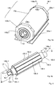
Im Rahmen der vorliegenden Beschreibung wird unter der Steckverbindung eine Verbindung zweier Elektromotor-Module verstanden, die so ausgebildet ist, dass sie durch eine axiale Bewegung geschlossen werden kann. Eine Steckverbindung weist ein männliches Steckverbinder-Element und ein weibliches Steckverbinder-Element auf, die miteinander die Steckverbindung bilden.In the context of the present description, the plug connection is understood to mean a connection between two electric motor modules which is designed such that it can be closed by an axial movement. A connector has a male connector element and a female connector element, which together form the connector.
Vorzugsweise umfasst die Steckverbindung (a) einen ersten Axial-Steckverbinder und (b) einen zweiten Axial-Steckverbinder, wobei der erste Axial-Steckverbinder auf einer ersten Seite seitlich neben der Rotorwelle angeordnet ist und der zweite Axial-Steckverbinder auf einer zweiten Seite gegenüber der ersten Seite seitlich neben der Rotorwelle angeordnet ist. Eine derartige Anordnung führt zu einer geringen Bauhöhe.The plug connection preferably comprises (a) a first axial plug connector and (b) a second axial plug connector, the first axial plug connector being arranged laterally next to the rotor shaft on a first side and the second axial plug connector being arranged on a second side opposite the first side is arranged laterally next to the rotor shaft. Such an arrangement leads to a low overall height.
Günstig ist es, wenn der zumindest eine Kühlmedium-Anschluss im ersten Axial-Steckverbinder angeordnet ist und der zumindest eine Strom-Anschluss im zweiten Axial-Steckverbinder angeordnet ist. Auf diese Weise werden spannungsführende Teile von fluidführenden, insbesondere wasserführenden, Teilen getrennt. Das erhöht die Betriebssicherheit des Elektromotors.It is advantageous if the at least one cooling medium connection is arranged in the first axial connector and the at least one current connection is arranged in the second axial connector. In this way, live parts are separated from fluid-carrying, especially water-carrying, parts. This increases the operational safety of the electric motor.
Vorzugsweise sind der erste Axial-Steckverbinder und der zweite Axial-Steckverbinder durch eine Bewegung der Elektromotor-Module in einer Koppelrichtung aufeinander zu miteinander koppelbar. Besonders günstig ist es, wenn die Koppelrichtung in axialer Richtung bezüglich der Rotorwelle verläuft. In anderen Worten ist es in diesem Fall möglich, die Steckverbindung dadurch zu schließen, dass die beiden Elektromotor-Module in axialer Richtung aufeinander zu bewegt werden. Besonders günstig ist es in diesem Fall, wenn auf diese Weise auch die Rotorwellen miteinander gekoppelt werden können. Das erlaubt eine besonders einfache Montage.The first axial connector and the second axial connector can preferably be coupled to one another by moving the electric motor modules in a coupling direction. It is particularly favorable if the coupling direction runs in the axial direction with respect to the rotor shaft. In other words, in this case it is possible to close the plug connection by moving the two electric motor modules towards one another in the axial direction. In this case, it is particularly favorable if the rotor shafts can also be coupled to one another in this way. This allows a particularly simple assembly.
Vorzugsweise besitzt das erste Elektromotor-Modul einen Quer-Steckverbinder, der einen Quer-Kühlmediumanschluss, einen Quer-Datenleitungsanschluss und einen Quer-Antriebsstromanschlusss hat und dessen Koppelrichtung quer zur axialen Richtung verläuft. Über einen solchen Quer-Steckverbinder kann das Elektromotor-Modul und damit der Elektromotor als Ganzes einfach angeschlossen werden.The first electric motor module preferably has a cross connector which has a cross cooling medium connection, a cross data line connection and a cross drive current connection and whose coupling direction runs transversely to the axial direction. The electric motor module and thus the electric motor as a whole can be easily connected via such a cross connector.
Günstig ist es, wenn der erste Axial-Steckverbinder einen ersten Sammel-Steckverbinder aufweist, wobei der erste Sammel-Steckverbinder zumindest zwei Anschlüsse umgibt und mit einem zweiten Sammel-Steckverbinder des zweiten Axial-Steckverbinders dichtend verbunden ist. Auf diese Weise werden, beispielsweise für den Kühlmedium-Anschluss, zwei Dichtungen bereitgestellt, nämlich einmal die Dichtung des Sammel-Steckverbinders und ein zweites Mal für den Kühlmedium-Anschluss selbst. Sollte eine der beiden Dichtungen undicht werden, so kommt es dennoch nicht zu einem Austreten von Kühlmedium.It is expedient for the first axial connector to have a first common connector, the first common connector surrounding at least two connections and being sealingly connected to a second common connector of the second axial connector. In this way, two seals are provided, for example for the cooling medium connection, namely one for the seal of the collective connector and a second time for the cooling medium connection itself. If one of the two seals becomes leaky, however, one does not occur Leakage of cooling medium.
Unter dem Kühlmedium wird vorzugsweise Kühlflüssigkeit, insbesondere Kühlwasser, verstanden.The cooling medium is preferably understood to mean cooling liquid, in particular cooling water.
Vorzugsweise ist der Kühlmedium-Anschluss mit einem Kühlkanal verbunden, der durch die Rotorwelle verläuft. Besonders günstig ist es in dem Fall, wenn das erste Elektromotor-Modul ein gesteuertes, insbesondere geregeltes Ventil aufweist, mittels dem ein Kühlmediumstrom an Kühlmedium veränderbar ist. Vorzugsweise besitzen alle Elektromotor-Module entsprechende Ventile. Bei diesen Ventilen kann es sich beispielsweise um Proportionalventile handeln.The cooling medium connection is preferably connected to a cooling channel which runs through the rotor shaft. It is particularly favorable in the case when the first electric motor module has a controlled, in particular regulated valve, by means of which a cooling medium flow of cooling medium can be changed. All electric motor modules preferably have corresponding valves. These valves can, for example, be proportional valves.
Günstig ist es, wenn das erste Elektromotor-Modul eine Elektronik-Baugruppe aufweist, die ausgebildet ist zum Bestromen von Wicklungsköpfen des Elektromotor-Moduls, wobei das Elektromotor-Modul in diesem Fall gemäß einer bevorzugten Ausführungsform eine Baugruppen-Kühlleitung besitzt, die zum Kühlen der Elektronik-Baugruppe angeordnet ist. Diese Baugruppen-Kühlleitung ist mit dem Kühlmedium-Anschluss verbunden.It is expedient for the first electric motor module to have an electronic assembly which is designed to energize winding heads of the electric motor module, the electric motor module in this case, in accordance with a preferred embodiment, having an assembly cooling line which is used to cool the Electronics assembly is arranged. This assembly cooling line is connected to the cooling medium connection.
Besonders günstig ist es, wenn das Elektromotor-Modul ein gesteuertes, insbesondere geregeltes, Baugruppenventil zum Verändern des Kühlmittelstroms zur Elektronik-Baugruppe und/oder ein gesteuertes, insbesondere geregeltes, Statorventil zum Verändern des Kühlmediumstroms zum Stator und/oder zum Rotor aufweist. Es ist in diesem Fall möglich, den Strom an Kühlmedium zur elektronischen Baugruppe und zum Stator und/oder zum Rotor unabhängig voneinander zu steuern oder zu regeln. Das ermöglichst es, die Kühlleistung, die das Kühlmedium aufzubringen vermag, dort zu konzentrieren, wo diese Kühlleistung am dringendsten benötigt wird.It is particularly favorable if the electric motor module has a controlled, in particular regulated, assembly valve for changing the coolant flow to the electronic assembly and / or a controlled, in particular regulated, stator valve for changing the coolant flow to the stator and / or to the rotor. In this case, it is possible to control or regulate the flow of cooling medium to the electronic assembly and to the stator and / or to the rotor independently of one another. This makes it possible to concentrate the cooling capacity that the cooling medium can apply where this cooling capacity is most urgently needed.
Vorzugsweise umfasst die elektronische Baugruppe zumindest ein Thermometer zum Erfassen der Temperatur der elektronischen Baugruppe, wobei das Baugruppen-Ventil vorzugsweise zum Regeln des Kühlmediumstroms anhand der von diesem Thermometer gemessenen Temperatur ausgebildet ist.The electronic assembly preferably comprises at least one thermometer for detecting the temperature of the electronic assembly, the assembly valve preferably being designed for regulating the cooling medium flow on the basis of the temperature measured by this thermometer.
Alternativ oder zusätzlich umfassen der Stator und/oder der Rotor ein Thermometer und das Stator-Ventil ist zum Regeln des Kühlmediumstroms anhand der von diesem Thermometer gemessenen Temperatur ausgebildet.Alternatively or additionally, the stator and / or the rotor comprise a thermometer and the stator valve is designed to regulate the cooling medium flow on the basis of the temperature measured by this thermometer.
Günstig ist es, wenn (a) das erste Elektromotor-Modul ein erstes Modul-Gehäuse hat, das eine erste Gehäuse-Koppelstruktur aufweist, (b) das zweite Elektromotor-Modul ein zweites Modul-Gehäuse hat, das eine zweite Gehäuse-Koppelstruktur aufweist, (c) die Elektromotor-Module mittels der Gehäuse-Koppelstrukturen formschlüssig miteinander verbunden sind, (d) eine erste Gehäuse-Koppelstruktur zumindest teilweise durch einen ersten konischen Gehäusering gebildet ist, (e) die zweite Gehäuse-Koppelstruktur zumindest teilweise durch zweiten konischen Gehäusering gebildet ist, (f) die konischen Gehäuseringe mittels einer Koppel-Schelle verbunden sind, die eine zumindest abschnittsweise konische Innenfläche hat und (g) die Koppel-Schelle zum formschlüssigen drehfesten Verbinden mit der Gehäuse-Koppelstruktur ausgebildet ist. Auf diese Weise können die Elektromotor-Module einfach miteinander verbunden werden, ohne dass es beim Anliegen von Drehmomenten an unterschiedlichen Stellen der Rotorwelle dazu kommen kann, dass sich die Elektromotor-Module gegeneinander verdrehen.It is expedient if (a) the first electric motor module has a first module housing that has a first housing coupling structure, (b) the second electric motor module has a second module housing that has a second housing coupling structure , (c) the electric motor modules are positively connected to one another by means of the housing coupling structures, (d) a first housing coupling structure is at least partially formed by a first conical housing ring, (e) the second housing coupling structure is at least partially formed by a second conical housing ring is formed, (f) the conical housing rings connected by means of a coupling clamp are, which has an at least partially conical inner surface and (g) the coupling clamp is designed for positive locking connection with the housing coupling structure. In this way, the electric motor modules can be easily connected to one another without the torque of the electric motor modules rotating against one another at different points on the rotor shaft.
Günstig ist es, wenn (a) die Koppel-Schelle einen Schellen-Vorsprung zum Eingreifen in eine Gehäuse-Ausnehmung der Gehäuse-Koppelstruktur aufweist und/oder (b) das Gehäuse einen Gehäuse-Vorsprung zum Eingreifen in eine Schellen-Ausnehmung der Schelle aufweist und/oder (c) der Elektromotor einen Passstift aufweist, der in Gehäuse-Ausnehmung und die Schellen-Ausnehmung eingreift.It is expedient if (a) the coupling clamp has a clamp projection for engaging in a housing recess of the housing coupling structure and / or (b) the housing has a housing projection for engaging in a clamp recess of the clamp and / or (c) the electric motor has a dowel pin which engages in the housing recess and the clamp recess.
In ihrer allgemeinsten Form löst die Erfindung das Problem durch ein gattungsgemäßes Elektroauto, bei dem (e) der Elektromotor aus einem ersten Elektromotor-Modul und zumindest einem zweiten Elektromotor-Modul aufgebaut ist, und bei dem (f) die Elektromotor-Module bezüglich einer Motor-Drehachse hintereinander angeordnet sind und eine gemeinsame Rotorwelle haben oder gekoppelte Rotorwellen besitzen. Es ist möglich und bevorzugt, nicht aber notwendig, dass die (g) das erste Elektromotor-Modul und das zweite Elektromotor-Modul mittels einer Steckverbindung miteinander verbunden sind, die zumindest einen Kühlmedium-Anschluss für Kühlmedium, einen Daten-Anschluss für Daten auf einer elektrischen oder optischen Datenleitung und zumindest einen Strom-Anschluss für Leistungsstrom hat. Die im Folgenden genannten bevorzugten Ausführungsformen beziehen sich auch auf diese allgemeine Form der Erfindung.In its most general form, the invention solves the problem by a generic electric car, in which (e) the electric motor is constructed from a first electric motor module and at least a second electric motor module, and (f) the electric motor modules with respect to a motor -The axis of rotation are arranged one behind the other and have a common rotor shaft or have coupled rotor shafts. It is possible and preferred, but not necessary, that the (g) the first electric motor module and the second electric motor module are connected to one another by means of a plug-in connection which has at least one cooling medium connection for cooling medium, one data connection for data on one electrical or optical data line and at least one power connection for power current. The preferred embodiments mentioned below also relate to this general form of the invention.
Günstig ist es, wenn der Elektromotor eine Elektromotor-Bauhöhe hat, und die Batterie eine Batterie-Bauhöhe hat, wobei die Elektromotor-Bauhöhe der Batterie-Bauhöhe weitgehend entspricht.It is favorable if the electric motor has an electric motor height and the battery has a battery height, the electric motor height largely corresponding to the battery height.
Vorteilhaft an diesem Elektrofahrzeug ist, dass der Elektromotor und die Batterie auf gleicher Höhe angeordnet werden können, was eine bevorzugte Ausführungsform darstellt und dazu führt, dass die Bauhöhe, die für den Elektromotor und die Batterie vorgesehen werden muss, klein gewählt werden kann. Besonders günstig ist es, wenn, was ebenfalls eine bevorzugte Ausführungsform darstellt, sowohl die Batterien als auch der Elektromotor unterhalb eines Niveaus angeordnet sind, auf dem sich der Fahrersitz befindet. In anderen Worten sind Motor und Batterie dann vollständig unter dem Fahrersitz angeordnet. Das führt dazu, dass der Schwerpunkt des Elektrofahrzeugs so tief liegt, dass sich eine gute Straßenlage ergibt.An advantage of this electric vehicle is that the electric motor and the battery can be arranged at the same height, which is a preferred embodiment and means that the overall height that must be provided for the electric motor and the battery can be chosen to be small. It is particularly cheap if, which is also a preferred embodiment, both the batteries and the electric motor are arranged below a level at which the driver's seat is located. In other words, the engine and battery are then completely located under the driver's seat. As a result, the center of gravity of the electric vehicle is so low that there is good road holding.
Besonders vorteilhaft ist, dass diese Anpassung der Bauhöhen eine Modularisierung von Batterien und Elektromotor ermöglicht. Das wiederum gestattet es, die Herstellung von verschiedenen Modellen mit unterschiedlichen Antriebsleistungen rationell zu planen und zu fertigen.It is particularly advantageous that this adaptation of the heights enables modularization of batteries and electric motor. This in turn makes it possible to efficiently plan and manufacture the production of different models with different drive powers.
Im Rahmen der vorliegenden Beschreibung wird unter einem Elektrofahrzeug insbesondere ein Landfahrzeug verstanden, beispielsweise ein Elektroauto oder ein Elektro-Lastkraftwagen. Vorzugsweise hat das Elektrofahrzeug vier Räder.In the context of the present description, an electric vehicle is understood to mean in particular a land vehicle, for example an electric car or an electric truck. The electric vehicle preferably has four wheels.
Unter der Achse wird das Bauteil verstanden, an dem die Räder befestigt sind. Die mathematische Achse, um die die Räder rotieren, wird als Drehachse bezeichnet.The axis is the component to which the wheels are attached. The mathematical axis around which the wheels rotate is called the axis of rotation.
Die Elektromotor-Bauhöhe wird insbesondere berechnet anhand desjenigen gedachten Quaders minimalen Volumens, der 90% der Masse des Elektromotors enthält. In anderen Worten ist es möglich, dass kleinere Bereiche des Elektromotors auskragen oder Vorsprünge ausbilden, wenngleich dies oft nicht vorteilhaft ist.The height of the electric motor is calculated in particular on the basis of the imaginary cuboid of minimum volume which contains 90% of the mass of the electric motor. In other words, it is possible that smaller areas of the electric motor protrude or form projections, although this is often not advantageous.
Die Batterie-Bauhöhe wird auf die gleiche Weise berechnet.The battery height is calculated in the same way.
Unter dem Merkmal, dass die Elektromotor-Bauhöhe der Batterie-Bauhöhe weitgehend entspricht, wird insbesondere verstanden, dass sich die Elektromotor-Bauhöhe von der Batterie-Bauhöhe um höchstens 15% unterscheidet. In anderen Worten liegt ein Quotient aus Elektromotor-Bauhöhe als Zähler und Batterie-Bauhöhe als Nenner zwischen 0,85 und 1,15.The feature that the electric motor height largely corresponds to the battery height is understood in particular to mean that the electric motor height differs from the battery height by at most 15%. In other words, the quotient of the electric motor height as the numerator and the battery height as the denominator is between 0.85 and 1.15.
Vorzugsweise ist die die Elektromotor-Bauhöhe kleiner ist als die Batterie-Bauhöhe.The height of the electric motor is preferably smaller than the height of the battery.
Günstig ist es, wenn dass der Batterie-Massenschwerpunkt oberhalb des Elektromotor-Massenschwerpunkts liegt. Das ermöglicht es, Teile der Batterie höher zu bauen als die Batterie-Bauhöhe ist, und so den Bauraum im Elektroauto gut auszunutzen.It is favorable if the battery center of gravity lies above the center of gravity of the electric motor. This makes it possible to build parts of the battery higher than the overall height of the battery and thus make good use of the space in the electric car.
Gemäß einer bevorzugten Ausführungsform liegt der Elektromotor-Massenschwerpunkt unterhalb einer Sitzebene eines Fahrersitzes und/oder unterhalb eines Bodens eines Fahrgastraums. So ergibt sich in der Regel eine gute Straßenlage.According to a preferred embodiment, the center of gravity of the electric motor is below a seat level of a driver's seat and / or below a floor of a passenger compartment. This generally results in good road holding.
Günstig ist es, wenn der Elektromotor die Räder einer Achse über ein Differential antreibt. Alternativ ist es aber auch möglich, dass mehr als ein Elektromotor vorhanden ist, wobei zumindest einer der Elektromotoren lediglich ein Rad antreibt. Die etwaigen Drehgeschwindigkeitsunterschiede bei der Kurvenfahrt werden in diesem Fall elektronisch ausgeregelt.It is favorable if the electric motor drives the wheels of an axle via a differential. Alternatively, however, it is also possible for more than one electric motor to be present, at least one of the electric motors driving only one wheel. In this case, any differences in rotational speed when cornering are electronically corrected.
Vorzugsweise ist ein Elektrofahrzeug ein Fahrzeug, dessen Antriebsdrehmoment bei konstant 50 Kilometer pro Stunde zu zumindest 50% vom Elektromotor stammt. Besonders günstig ist es, wenn es sich um ein reines Elektrofahrzeug handelt, das heißt, dass die Räder ausschließlich elektrisch angetrieben sind.An electric vehicle is preferably a vehicle whose drive torque at a constant 50 kilometers per hour comes at least 50% from the electric motor. It is particularly favorable if it is a purely electric vehicle, which means that the wheels are driven exclusively by electricity.
Günstig ist es, wenn der Elektromotor vollständig zwischen den Achsen angeordnet ist. Hierunter ist insbesondere zu verstehen, dass der Elektromotor in einem Bereich angeordnet ist, der sich zwischen zwei Ebenen befindet, wobei jede der Ebenen vertikal verläuft und durch die Drehachsen der Räder des Elektrofahrzeugs bei Geradeausfahrt geht. Besonders günstig ist es, wenn der Abstand des Elektromotors zur ersten Achse möglichst wenig, vorzugsweise höchstens um den Faktor zwei, von einem Abstand von der zweiten Achse abweicht. Ein derartiges Elektrofahrzeug hat ein besonders kleines Massenträgheitsmoment bezüglich der Drehung um die Hochachse. Das Elektrofahrzeug hat daher besonders vorteilhafte Fahreigenschaften.It is advantageous if the electric motor is arranged entirely between the axes. This is to be understood in particular to mean that the electric motor is arranged in a region which is located between two levels, each of the levels running vertically and going through the axes of rotation of the wheels of the electric vehicle when driving straight ahead. It is particularly favorable if the distance between the electric motor and the first axis deviates as little as possible, preferably at most by a factor of two, from a distance from the second axis. Such an electric vehicle has a particularly small moment of inertia with respect to the rotation about the vertical axis. The electric vehicle therefore has particularly advantageous driving properties.
Günstig ist es, wenn der Abstand zwischen dem bezüglich der Längsachse des Elektrofahrzeugs vordersten Ende des Elektromotors, insbesondere des vorderen Elektromotor-Moduls, und dem hintersten Ende des Elektromotors, vorzugsweise dem hintersten Elektromotor-Modul, höchsten 15 % des Achsabstands beträgt. Vorzugsweise besitzt das Elektrofahrzeug einen Fahrzeugboden. Der Elektromotor und die Batterie können auf dem Fahrzeugboden angeordnet sein. Alternativ sind sie am Fahrzeugboden hängend montiert. Die hängende Montage hat den Vorteil, besonders leicht durchgeführt werden zu können. Die Montage auf dem Fahrzeugboden bietet Vorteile bei dem Schutz der Batterien gegen Einwirkungen von außen.It is advantageous if the distance between the front end of the electric motor, in particular the front electric motor module, with respect to the longitudinal axis of the electric vehicle, and the rearmost end of the electric motor, preferably the rearmost electric motor module, is at most 15% of the center distance. The electric vehicle preferably has a vehicle floor. The electric motor and the battery can be arranged on the vehicle floor. Alternatively, they are suspended from the vehicle floor. The hanging assembly has the advantage that it can be carried out particularly easily. Mounting on the vehicle floor offers advantages in protecting the batteries against external influences.
Die Erfindung löst das Problem zudem durch ein gattungsgemäßes Elektrofahrzeug, bei dem der Elektromotor aus mindestens zwei Elektromotor-Modulen aufgebaut ist, wobei die Elektromotor-Module bezüglich einer Motor-Drehachse hintereinander angeordnet sind und mehrere gekoppelte Rotorwellen oder eine gemeinsame Rotorwelle haben. Dies ist eine unabhängige Erfindung in Bezug auf die oben genannte Erfindung. Es ist jedoch möglich und bevorzugt, dass bei einem derartigen Elektrofahrzeug die Elektromotor-Bauhöhe der Batterie-Bauhöhe weitgehend entspricht. Die im Folgenden beschriebenen bevorzugten Ausführungsformen beziehen sich auf beide Erfindungen. Die Elektromotor-Module sind vorzugsweise baugleich ausgebildet und miteinander verbunden.The invention also solves the problem by a generic electric vehicle, in which the electric motor is constructed from at least two electric motor modules, the electric motor modules being arranged one behind the other with respect to a motor axis of rotation and having a plurality of coupled rotor shafts or a common rotor shaft. This is an independent invention with respect to the above invention. However, it is possible and preferred that the height of the electric motor corresponds largely to the height of the battery in such an electric vehicle. The preferred embodiments described below relate to both inventions. The electric motor modules are preferably of identical construction and are connected to one another.
Gemäß einer alternativen Ausführungsform der Erfindung entspricht die Elektromotor-Bauhöhe nicht weitgehend der Batterie-Bauhöhe. So kann die Elektromotor-Bauhöhe kleiner sein als die Batterie-Bauhöhe. Auf diese Weise kann der Massenschwerpunkt des Elektrofahrzeugs besonders tief liegen, was die Straßenlage verbessert.According to an alternative embodiment of the invention, the height of the electric motor does not largely correspond to the height of the battery. For example, the height of the electric motor can be smaller than the height of the battery. In this way, the center of gravity of the electric vehicle can be particularly low, which improves road holding.
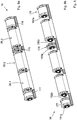
Vorzugsweise ist zwischen zwei Elektromotor-Modulen ein Wellenlager für die durchgehende Rotorwelle des Elektromotors angeordnet. Auf diese Weise werden Schwingungen des Rotors vermindert, wenn das Fahrzeug über unebenen Untergrund fährt.A shaft bearing for the continuous rotor shaft of the electric motor is preferably arranged between two electric motor modules. In this way, vibrations of the rotor are reduced when the vehicle is driving over uneven ground.
Die Erfindung löst das Problem zudem durch ein Elektrofahrzeug mit (a) einer ersten Achse, (b) einer zweiten Achse, (c) einem Elektromotor zum Antreiben von zumindest einer der Achsen, der eine Elektromotor-Bauhöhe hat, und (d) einer Batterie zum Versorgen des Elektromotors mit elektrischer Energie, die eine Batterie-Bauhöhe hat, wobei der Elektromotor ein Außenläufer ist, wobei der Rotor einen, insbesondere T-förmigen, Außenabschnitt hat und wobei der Stator zumindest ein Spulenpaket aufweist, das zwischen dem Außenabschnitt und der Rotorwelle angeordnet ist. Die oben und im Folgenden beschriebenen bevorzugten Ausführungsformen beziehen sich auch auf diese Erfindung. Es ist möglich, nicht aber notwendig, dass der Elektromotor aus einem ersten Elektromotor-Modul und zumindest einem zweiten Elektromotor-Modul aufgebaut ist, wobei die Elektromotor-Module bezüglich einer Motor-Drehachse hintereinander angeordnet sind und eine gemeinsame Rotorwelle haben oder gekoppelte Rotorwellen besitzen. Es ist zudem möglich, nicht aber notwendig, dass das erste Elektromotor-Modul und das zweite Elektromotor-Modul mittels einer Steckverbindung miteinander verbunden sind, die zumindest einen Kühlmedium-Anschluss für Kühlmedium und zumindest einen Strom-Anschluss für Leistungsstrom hat.The invention also solves the problem with an electric vehicle having (a) a first axle, (b) a second axle, (c) an electric motor for driving at least one of the axles, which has an electric motor height, and (d) a battery for supplying the electric motor with electrical energy, which has a battery height, the electric motor being an external rotor, the rotor being one, in particular T-shaped, outer portion and wherein the stator has at least one coil package which is arranged between the outer portion and the rotor shaft. The preferred embodiments described above and below also relate to this invention. It is possible, but not necessary, for the electric motor to be constructed from a first electric motor module and at least one second electric motor module, the electric motor modules being arranged one behind the other with respect to a motor axis of rotation and having a common rotor shaft or having coupled rotor shafts. It is also possible, but not necessary, for the first electric motor module and the second electric motor module to be connected to one another by means of a plug connection which has at least one cooling medium connection for cooling medium and at least one current connection for power current.
Der T-förmige Außenabschnitt kann auch als Rotorglocke bezeichnet werden. Auf diese Weise ergibt sich ein hohes Drehmoment bei gleichzeitig geringer Bauhöhe. In anderen Worten ragt das zumindest eine Spulenpaket zwischen den Außenabschnitt und den verbleibenden Teil des Rotors. Es ist möglich, nicht aber notwendig, dass die Rotorglocke symmetrisch bezüglich einer Symmetrieebene, die senkrecht zur Motor-Drehachse verläuft, ist.The T-shaped outer section can also be referred to as a rotor bell. This results in a high torque with a low overall height. In other words, the at least one coil package projects between the outer section and the remaining part of the rotor. It is possible, but not necessary, for the rotor bell to be symmetrical with respect to a plane of symmetry that is perpendicular to the axis of rotation of the motor.
Dies ist für ein Elektrofahrzeug gemäß dem Oberbegriff von Anspruch 1 eine unabhängige Erfindung in Bezug auf die anderen oben genannten Erfindungen. Es ist jedoch möglich und bevorzugt, dass bei einem derartigen Elektrofahrzeug die Elektromotor-Bauhöhe der Batterie-Bauhöhe weitgehend entspricht und/oder dass der Elektromotor aus zumindest zwei Elektromotor-Modulen aufgebaut ist und die Elektromotor-Module bezüglich einer Motor-Drehachse hintereinander angeordnet sind und eine gemeinsame Rotorwelle haben oder gekoppelte Rotorwellen besitzen. Die im Folgenden beschriebenen bevorzugten Ausführungsformen beziehen sich auf alle drei Erfindungen.For an electric vehicle according to the preamble of
Gemäß einer bevorzugten Ausführungsform sind die Rotorglocke und die Rotorwelle formschlüssig miteinander verbunden. Beispielsweise hat die Rotorglocke eine Innenverzahnung und die Welle des Rotors eine Außenverzahnung, wobei die Rotorglocke mittels der Innenverzahnung und der Außenverzahnung drehfest mit der Welle verbunden ist. Das erleichtert die Montage.According to a preferred embodiment, the rotor bell and the rotor shaft are positively connected to one another. For example, the rotor bell has internal teeth and the shaft of the rotor has external teeth, the rotor bell being connected to the shaft in a rotationally fixed manner by means of the internal teeth and the external teeth. This makes assembly easier.
Vorzugsweise umfasst der Außenabschnitt auf seiner radial einwärtigen Seite Permanentmagnete. Das zumindest eine Spulenpaket ist elektrisch, mechanisch und/oder thermisch mit einer Kappe des Stators kontaktiert. In anderen Worten ist das zumindest eine Spulenpaket so an der Kappe des Stators befestigt, dass die Abwärme des Spulenpakets aktiv oder passiv beim Betrieb des Elektrofahrzeugs abgeführt wird.The outer section preferably comprises permanent magnets on its radially inward side. The at least one coil package is contacted electrically, mechanically and / or thermally with a cap of the stator. In other words, the at least one coil package is fastened to the cap of the stator in such a way that the waste heat from the coil package is actively or passively removed when the electric vehicle is in operation.
Günstig ist es, wenn der Rotor eine Hohlwelle aufweist. Auf diese Weise wird die schwingende Masse reduziert. Zudem ist es möglich, dass der Rotor von innen gekühlt wird, indem ein Kühlfluid, insbesondere Luft oder Kühlflüssigkeit, beispielsweise Wasser, durch die Hohlwelle geschickt wird.It is favorable if the rotor has a hollow shaft. In this way, the vibrating mass is reduced. In addition, it is possible for the rotor to be cooled from the inside by sending a cooling fluid, in particular air or cooling liquid, for example water, through the hollow shaft.
Vorzugsweise liegt ein Batterie-Massenschwerpunkt der Batterie und/oder ein Elektromotor-Massenschwerpunkt des Elektromotors zwischen den Achsen, insbesondere in einem zentralen Drittel, vorzugsweise einem zentralen Fünftel (Quintil). Wenn das Fahrzeug so steht, dass beide Achsen sich entlang einer horizontalen Ebene erstrecken, verläuft eine erste Vertikalebene so, dass sich die erste Achse entlang der ersten Vertikalachse erstreckt. Eine zweite Vertikalachse verläuft so, dass sich die zweite Achse entlang der zweiten Vertikalachse erstreckt. Die beiden Vertikalachsen verlaufen parallel zueinander. Das zentrale Drittel ist derjenige Bereich zwischen zwei weiteren Vertikalachsen, deren Abstand von einem Drittel des Abstands von erster und zweiter Vertikalachse entspricht, deren Abstand von einem Mittelpunkt, der genau zwischen der ersten und der zweiten Vertikalachse liegt, gleich ist. Der entsprechende Massenschwerpunkt ist dann zwischen diesen beiden zusätzlichen Vertikalachsen angeordnet. Eine derartige Anordnung der Batterie bzw. des Elektromotors führt zu besonders günstigen Fahreigenschaften, da das Massenträgheitsmoment bezüglich einer Gier-, Nick- oder Rollbewegung des Elektrofahrzeugs besonders klein ist.A battery center of gravity of the battery and / or an electric motor center of gravity of the electric motor is preferably between the axes, in particular in a central third, preferably a central fifth (quintile). If the vehicle is standing such that both axes extend along a horizontal plane, a first vertical plane runs such that the first axis extends along the first vertical axis. A second vertical axis extends such that the second axis extends along the second vertical axis. The two vertical axes run parallel to each other. The central third is the area between two further vertical axes, the distance of which corresponds to a third of the distance from the first and second vertical axes, the distance from a center, which lies exactly between the first and the second vertical axis, is the same. The corresponding center of mass is then arranged between these two additional vertical axes. Such an arrangement of the battery or of the electric motor leads to particularly favorable driving properties, since the mass moment of inertia with respect to a yaw, pitch or roll movement of the electric vehicle is particularly small.
Vorzugsweise hat der Fahrgastraum einen mitteltunnelfreien Boden. Da die Batterie und der Elektromotor gleiche Bauhöhen haben, ist ein Mitteltunnel zum Aufnehmen eines vergrößerten Elektromotors entbehrlich. Der Erfindung liegt die Erkenntnis zugrunde, dass es vorteilhaft ist, das Drehmoment des Elektromotors dadurch zu erhöhen, dass er lang ausgebildet wird. Bisherige Fahrzeuge setzen auf Elektromotoren mit möglichst großem Rotor-Durchmesser und geringer Baulänge, um das Drehmoment zu erhöhen. Das aber führt zu einer nachteiligen Lage des Elektromotor-Massenschwerpunkts und/oder macht einen Mitteltunnel notwendig. Das erfindungsgemäße Elektrofahrzeug kommt ohne Mitteltunnel aus.The passenger compartment preferably has a central tunnel-free floor. Since the battery and the electric motor have the same overall height, a central tunnel for accommodating an enlarged electric motor is unnecessary. The invention is based on the finding that it is advantageous to increase the torque of the electric motor by making it long. Previous vehicles rely on electric motors with the largest possible rotor diameter and a small overall length in order to increase the torque. However, this leads to a disadvantageous position of the center of gravity of the electric motor and / or makes a center tunnel necessary. The electric vehicle according to the invention manages without a central tunnel.
Unter dem Merkmal, dass der Fahrgastraum einen mitteltunnelfreien Boden hat, wird insbesondere verstanden, dass der Boden im technischen Sinne eben ist. In anderen Worten sind Erhebungen zwar möglich, die maximale Erhebung ist aber klein. Insbesondere beträgt die maximale Erhebung zwischen Fahrer- und Beifahrersitz höchstens 10 Zentimeter über einer gedachten Ausgleichsebene durch den Boden des Fahrgastraumes.The feature that the passenger compartment has a floor free of a central tunnel means in particular that the floor is flat in the technical sense. In other words, surveys are possible, but the maximum survey is small. In particular, the maximum elevation between the driver and front passenger seat is at most 10 centimeters above an imaginary level of compensation through the floor of the passenger compartment.
Vorzugsweise besitzt das Elektrofahrzeug eine Längsachse und die Motor-Drehachse erstreckt sich entlang der Längsachse. Hierunter ist insbesondere zu verstehen, dass es zwar möglich, nicht aber notwendig ist, dass sich die Motor-Drehachse parallel zur Längsachse erstreckt. Insbesondere ist ein Versatzwinkel zwischen der Motor-Drehachse und der Längsachse möglich, der vorzugsweise höchstens 20°, insbesondere höchstens 5°, beträgt.The electric vehicle preferably has a longitudinal axis and the motor axis of rotation extends along the longitudinal axis. This is to be understood in particular to mean that it is possible, but not necessary, for the motor axis of rotation to extend parallel to the longitudinal axis. In particular, an offset angle between the motor axis of rotation and the longitudinal axis is possible, which is preferably at most 20 °, in particular at most 5 °.
Vorzugsweise umfasst die Batterie zumindest zwei Batterie-Einheiten, wobei die Motor-Drehachse zwischen den Batterie-Einheiten verläuft. Unter dem Merkmal, dass die Motor-Drehachse zwischen den Batterie-Einheiten verläuft, wird verstanden, dass eine Projektion der Motor-Drehachse auf eine Ebene, entlang der sich die erste Achse und die zweite Achse erstrecken, zwischen einem ersten Batterieeinheit-Massenschwerpunkt der ersten Batterie-Einheit und einem zweiten Batterieeinheit-Massenschwerpunkt der zweiten Batterie-Einheit verläuft. Besonders günstig ist es, wenn die Drehachse so verläuft, dass - bezogen auf eine jeweilige Projektion auf die Ebene, entlang der die beiden Achsen verlaufen - die erste Batterie-Einheit von der zweiten Batterie-Einheit getrennt ist. In anderen Worten verläuft kein galvanisches Element einer Batterie-Einheit von einer Seite der Projektion der Drehachse auf die andere. Es ist allerdings möglich, dass elektrische Verbinder, insbesondere Kabel, von einer Seite der Projektion der Drehachse auf die andere Seite verlaufen.The battery preferably comprises at least two battery units, the motor axis of rotation running between the battery units. The feature that the motor axis of rotation runs between the battery units is understood to mean that a projection of the motor axis of rotation onto a plane along which the first axis and the second axis extend is between a first center of gravity of the first battery unit Battery unit and a second battery unit center of gravity of the second battery unit runs. It is particularly expedient if the axis of rotation runs in such a way that - based on a respective projection onto the plane along which the two axes run - the first battery unit is separated from the second battery unit. In other words, there is no galvanic Element of a battery unit from one side of the projection of the axis of rotation to the other. However, it is possible that electrical connectors, in particular cables, run from one side of the projection of the axis of rotation to the other side.
Vorzugsweise besitzt der Elektromotor einen Rotor mit Permanentmagneten. Es ist dabei möglich, dass der Elektromotor ein Innenläufermotor ist. Alternativ ist der Elektromotor ein Außenläufermotor.The electric motor preferably has a rotor with permanent magnets. It is possible that the electric motor is an internal rotor motor. Alternatively, the electric motor is an external rotor motor.
Das Elektrofahrzeug besitzt vorzugsweise ein Differential und ein Getriebe, das im Drehmomentfluss zwischen dem Motor und dem Differential angeordnet ist. Es ist möglich, nicht aber notwendig, dass das Elektrofahrzeug ein zweites Differential und eines zweites Getriebe aufweist, das im Drehmomentfluss zwischen dem Motor und dem zweiten Differential angeordnet ist. Das erste Differential treibt vorzugsweise die Räder der Vorderachse an. Das zweite Differential treibt vorzugsweise die Räder der Hinterachse an. Mit zwei Differentialen kann ein Vierradantrieb realisiert werden. Das erste Differential und/oder das zweite Differential sind jeweils drehstarr mit dem entsprechenden Rotor des Elektromotors gekoppelt.The electric vehicle preferably has a differential and a transmission, which is arranged in the torque flow between the motor and the differential. It is possible, but not necessary, for the electric vehicle to have a second differential and a second transmission, which is arranged in the torque flow between the motor and the second differential. The first differential preferably drives the wheels of the front axle. The second differential preferably drives the wheels of the rear axle. A four-wheel drive can be realized with two differentials. The first differential and / or the second differential are each rotationally rigidly coupled to the corresponding rotor of the electric motor.
Der Elektromotor kann besonders einfach gefertigt werden, wenn er einen Rotor mit Permanentmagneten aufweist, wobei der Rotor in Längsrichtung verlaufende Nuten aufweist, in denen die Permanentmagneten angeordnet sind. Beispielsweise sind die Permanentmagneten in die Nuten eingeschoben.The electric motor can be manufactured particularly simply if it has a rotor with permanent magnets, the rotor having grooves running in the longitudinal direction, in which the permanent magnets are arranged. For example, the permanent magnets are inserted into the grooves.
Um besonders hohe Drehmomente zu erzielen und/oder einfach einen Vierradantrieb zu realisieren ist es günstig, wenn das Elektrofahrzeug einen zweiten Elektromotor, der aus zumindest zwei Zweitelektromotor-Modulen aufgebaut ist, umfasst, wobei die Zweitelektromotor-Module einen gemeinsamen zweiten Rotor aufweisen und wobei der erste Rotor und der zweite Rotor parallel zueinander verlaufen. Es ist dabei möglich, dass der erste Elektromotor die Räder der ersten Achse antreibt und der zweite Elektromotor die Räder der zweiten Achse antreibt. Alternativ ist es auch möglich, dass der erste Elektromotor und der zweite Elektromotor gemeinsam die Räder einer der Achsen, beispielsweise der Vorderachse und/oder der Hinterachse, antreiben.In order to achieve particularly high torques and / or to simply implement a four-wheel drive, it is favorable if the electric vehicle comprises a second electric motor which is constructed from at least two second electric motor modules, the second electric motor modules having a common second rotor, and the the first rotor and the second rotor run parallel to one another. It is possible that the first electric motor drives the wheels of the first axis and the second electric motor drives the wheels of the second axis. Alternatively, it is also possible for the first electric motor and the second electric motor to jointly drive the wheels of one of the axles, for example the front axle and / or the rear axle.
Gemäß einer bevorzugten Ausführungsform umfasst der Elektromotor einen zweiten Elektromotor, der vorzugsweise aus zumindest zwei Elektromotor-Modulen aufgebaut ist, einen dritten Elektromotor, der vorzugsweise aus zumindest zwei Elektromotor-Modulen aufgebaut ist, und einen vierten Elektromotor, der vorzugsweise aus zumindest zwei Elektromotor-Modulen aufgebaut ist, wobei jeder der Elektromotoren jeweils ein Rad, insbesondere über ein Winkelgetriebe, antreibt. Es ist günstig, wenn alle Elektromotor-Module baugleich sind. Es ist dann günstig, wenn alle Motoren von einer Motorsteuerung so angesteuert sind, dass sie ein gleiches Drehmoment auf das jeweilige Rad aufbringen, wobei vorzugsweise ein Durchdrehen unterdrückt wird. Eine solche Anti-Schlupf-Regelung gehört zum Stand der Technik und wird daher nicht weiter erläutert.According to a preferred embodiment, the electric motor comprises a second electric motor, which is preferably made up of at least two electric motor modules, a third electric motor, which is preferably made up of at least two electric motor modules, and a fourth electric motor, which is preferably made up of at least two electric motor modules is constructed, each of the electric motors driving a wheel, in particular via an angular gear. It is advantageous if all electric motor modules are identical. It is then favorable if all the motors are controlled by a motor controller in such a way that they apply the same torque to the respective wheel, preferably preventing the wheel from spinning. Such an anti-slip control is part of the prior art and is therefore not further explained.
Vorzugsweise weist der Stator einen Basiskörper und ein zweites Spulenpaket auf, wobei das Spulenpaket an einer Kappe des Stators befestigt ist und wobei die Kappe reversibel am Basiskörper befestigt ist. So ist der Elektromotor leicht zu montieren.The stator preferably has a base body and a second coil package, the coil package being fastened to a cap of the stator and the cap being reversibly fastened to the base body. So the electric motor is easy to assemble.
Gemäß einer bevorzugten Ausführungsform hat (a) das erste Elektromotor-Modul einen ersten Rotor, der eine erste Rotorwelle besitzt, und dessen Rotorwelle hat eine erste Wellen-Koppelstruktur, (b) das zweite Elektromotor-Modul einen zweiten Rotor, der eine zweite Rotorwelle besitzt, und dessen zweite Rotorwelle hat eine zweite Wellen-Koppelstruktur, wobei das Elektroauto (c) eine Drehlagerung, mittels der die erste Rotorwelle gelagert ist, umfasst und wobei (d) die erste Rotorwelle und die zweite Rotorwelle mittels der Koppelstrukturen formschlüssig miteinander gekoppelt sind. Die Erfindung betrifft zudem einen Elektromotor mit den genannten Eigenschaften, der insbesondere für ein Elektrofahrzeug ausgebildet ist, das ist aber nicht notwendig.According to a preferred embodiment, (a) the first electric motor module has a first rotor that has a first rotor shaft and its rotor shaft has a first shaft coupling structure, (b) the second electric motor module has a second rotor that has a second rotor shaft , and its second rotor shaft has a second shaft coupling structure, the electric car (c) comprising a rotary bearing by means of which the first rotor shaft is mounted, and (d) the first rotor shaft and the second rotor shaft are positively coupled to one another by means of the coupling structures. The invention also relates to an electric motor with the properties mentioned, which is designed in particular for an electric vehicle, but this is not necessary.
Vorzugsweise sind die Koppelstrukturen zumindest teilweise von der Drehlagerung umgeben.The coupling structures are preferably at least partially surrounded by the rotary bearing.
Vorteilhaft an der Erfindung ist, dass der Elektromotor auf diese Weise sehr kompakt gebaut werden kann. So ist es gemäß einer bevorzugten Ausführungsform möglich, dass die Verbindung mittels der Koppelstrukturen am Gehäuse und an den Rotorwellen zu keiner zusätzlichen axialen Verlängerung der Baulänge führen.The advantage of the invention is that the electric motor can be built very compact in this way. According to a preferred embodiment, it is possible that the connection by means of the coupling structures on the housing and on the rotor shafts does not lead to any additional axial lengthening of the overall length.
Vorteilhaft ist zudem, dass eine derartige Koppelstruktur in der Regel vergleichsweise einfach zu fertigen ist. Es ist daher möglich, den Elektromotor aus zwei, drei, vier oder mehr Elektromotor-Modulen aufzubauen. Wie bei jeder modularen Bauweise führt die Modularisierung der einzelnen Komponenten in aller Regel zu einer effizienteren Fertigung.It is also advantageous that such a coupling structure is generally comparatively easy to manufacture. It is therefore possible to construct the electric motor from two, three, four or more electric motor modules. As with any modular design, the modularization of the individual components generally leads to more efficient production.
Gemäß einer bevorzugten Ausführungsform besitzt die Drehlagerung ein erstes Drehlager, das einen ersten Satz an Wälzkörpern, die ringförmig angeordnet sind, aufweist, und ein zweites Drehlager, das einen zweiten Satz an Wälzkörpern, die ringförmig und versetzt zum ersten Satz angeordnet sind. Die Wellen-Koppelstrukturen sind in diesem Fall vorzugsweise zumindest teilweise, besonders bevorzugt vollständig vom ersten Drehlager und vom zweiten Drehlager umgeben. Bei dem ersten Drehlager und/oder dem zweiten Drehlager handelt es sich beispielsweise um ein Wälzlager, insbesondere ein Kugellager.According to a preferred embodiment, the pivot bearing has a first pivot bearing, which has a first set of rolling elements, which are arranged in a ring, and a second pivot bearing, which has a second set of rolling elements, which are arranged in a ring and offset from the first set. In this case, the shaft coupling structures are preferably at least partially, particularly preferably completely surrounded by the first pivot bearing and by the second pivot bearing. The first pivot bearing and / or the second pivot bearing is, for example, a roller bearing, in particular a ball bearing.
Vorteilhaft an dieser Ausführungsform ist, dass die Koppelstrukturen jedes einzelnen Elektromotor-Moduls an beiden Seiten von zumindest einem Wälzlager gelagert sind. Zum Zusammenfügen von zwei Elektromotor-Modulen müssen lediglich die beiden Koppelstrukturen der jeweiligen Elektromotor-Module formschlüssig miteinander verbunden werden.It is advantageous in this embodiment that the coupling structures of each individual electric motor module are supported on both sides by at least one roller bearing. To join two electric motor modules, only the two coupling structures of the respective electric motor modules have to be connected to one another in a form-fitting manner.
Günstig ist es, wenn in dieser Anordnung die jeweils zu äußerst liegenden Drehlager der Elektromotor-Module aneinander angrenzen. Auf diese Weise wird ein besonders kompakter Elektromotor erhalten. Aufgrund der Modularisierbarkeit des Elektromotors eignet er sich gut für die Verwendung in Fahrzeugen, insbesondere in Personenkraftwagen. Allerdings ist dieser Elektromotor auch in anderen Fahrzeugen und auch in anderen Bereichen anwendbar.It is expedient if in this arrangement the rotary bearings of the electric motor modules, which are located to the extreme, are adjacent to one another. In this way, a particularly compact electric motor is obtained. Because the electric motor can be modularized, it is well suited for use in vehicles, especially in passenger cars. However, this electric motor can also be used in other vehicles and also in other areas.
Vorzugsweise besitzt die erste Wellen-Koppelstruktur einen sich in axialer Richtung erstreckenden Vorsprung. Die zweite Wellen-Koppelstruktur hat vorzugsweise einen sich ebenfalls in axialer Richtung erstreckenden Rücksprung, sodass die erste Wellen-Koppelstruktur und die zweite Koppelstruktur in axialer Richtung aneinander entlang einer Kontaktfläche anliegen. Günstig ist es, wenn die Kontaktflächen mit einer Winkelmessebene, die eine Drehachse des Rotors enthält, einen Winkel von höchstens 5° bildet. Auf diese Weise werden axiale Kräfte vermindert, die beim Anlegen eines Drehmoments an die Verbindung der Elektromotor-Module anderweitig entstehen würden.The first shaft coupling structure preferably has a projection extending in the axial direction. The second shaft coupling structure preferably has a recess that also extends in the axial direction, so that the first shaft coupling structure and the second coupling structure abut one another in the axial direction along a contact surface. It is favorable if the contact surfaces with a Angle measuring plane, which contains an axis of rotation of the rotor, forms an angle of at most 5 °. In this way, axial forces are reduced, which would otherwise arise when a torque is applied to the connection of the electric motor modules.
Es ist möglich, dass der Vorsprung und der Rücksprung asymmetrisch ausgebildet sind. In diesem Fall erstreckt sich eine erste Kontaktfläche, entlang der der Vorsprung und der Rücksprung aneinander anliegen, in einem anderen Winkel relativ zu der Winkelmessebene als die zweite Kontaktfläche. Insbesondere ist es möglich, dass einer der Winkel Null ist. In diesem Fall entsteht keinerlei axiale Kraft, wenn sich die Rotoren in eine erste Richtung drehen. Hingegen entsteht eine größere Kraft, wenn die Rotoren in die entgegengesetzte Richtung drehen.It is possible that the projection and the recess are asymmetrical. In this case, a first contact surface, along which the projection and the recess rest against one another, extends at a different angle relative to the angle measurement plane than the second contact surface. In particular, it is possible for one of the angles to be zero. In this case there is no axial force when the rotors rotate in a first direction. On the other hand, a greater force is created when the rotors turn in the opposite direction.
Vorzugsweise weist der Elektromotor zumindest eine Zusatzkomponente auf, die eine Zusatzkomponenten-Koppelstruktur mit einem sich in axialer Richtung erstreckenden Vorsprung hat, wobei die Zusatzkomponente mit einer der Koppelstrukturen eines Elektromotor-Moduls formschlüssig verbunden ist. Dadurch dass die Zusatzkomponente die gleiche Koppelstruktur hat wie die Elektromotor-Module, kann sie je nach Anforderung beliebig zwischen zwei Elektromotor-Modulen platziert werden. Bei der Zusatzkomponente handelt es sich beispielsweise um einen Drehgeber.The electric motor preferably has at least one additional component that has an additional component coupling structure with a projection that extends in the axial direction, the additional component being connected to one of the coupling structures of an electric motor module in a form-fitting manner. Because the additional component has the same coupling structure as the electric motor modules, it can be placed between two electric motor modules as required. The additional component is, for example, an encoder.
In diesem Fall weist der Elektromotor entsprechend einen Drehgeber auf, der eine Drehgeber-Koppelstruktur mit einem sich in axialer Richtung erstreckenden Vorsprung hat, wobei der Drehgeber mit einer der Koppelstrukturen eines Elektromotor-Moduls formschlüssig verbunden ist. Dadurch dass der Drehgeber die gleiche Koppelstruktur hat wie die Elektromotor-Module, kann er je nach Anforderung beliebig zwischen zwei Elektromotor-Modulen platziert werden.In this case, the electric motor accordingly has a rotary encoder which has a rotary encoder coupling structure with a projection which extends in the axial direction, the rotary encoder being positively connected to one of the coupling structures of an electric motor module. Because the encoder has the same coupling structure as the electric motor modules, it can be placed anywhere between two electric motor modules, depending on the requirements.
Es sei darauf hingewiesen, dass die Rotorwellen vorzugsweise aller Elektromotor-Module miteinander formschlüssig koppelbare Koppelstrukturen aufweisen.It should be pointed out that the rotor shafts, preferably of all electric motor modules, have coupling structures that can be coupled to one another in a form-fitting manner.
Alternativ oder zusätzlich handelt es sich bei der Zusatzkomponente um eine Bremse. Gemäß dieser Ausführungsform besitzt der Elektromotor eine Bremse, die eine Bremsen-Koppelstruktur mit einem in axialer Richtung sich erstreckenden Vorsprung hat, wobei die Bremse mit einer Koppelstruktur eines Elektromotor-Moduls oder des Drehgebers formschlüssig verbunden ist.Alternatively or additionally, the additional component is a brake. According to this embodiment, the electric motor has a brake which has a brake coupling structure with a projection which extends in the axial direction has, wherein the brake is positively connected to a coupling structure of an electric motor module or the rotary encoder.
Wiederum alternativ oder zusätzlich handelt es sich bei der Zusatzkomponente um eine Kupplung.Again, alternatively or additionally, the additional component is a clutch.
Ein zweiter Aspekt der Erfindung betrifft einen Elektromotor, der einen Stator, der Stator-Elektromagnete aufweist, und einen Rotor, der Permanentmagnete aufweist, umfasst, wobei die Rotorwelle einen Kühlkanal hat. Ein Elektrofahrzeug mit einem entsprechenden Elektromotor ist ebenfalls erfindungsgemäß. Günstig ist es, wenn dieser Elektromotor aus einem ersten Elektromotor-Modul und einem zweiten Elektromotor-Modul aufgebaut ist, wobei die Elektromotor-Module die oben angegebenen Eigenschaften haben. Die erste Rotorwelle und die zweite Rotorwelle sind mittels der Wellen-Koppelstrukturen formschlüssig miteinander gekoppelt, wobei der Kühlkanal vorzugsweise durch den ersten Rotor und den zweiten Rotor verläuft. Günstig ist es zudem, wenn die Koppelstrukturen zumindest teilweise von der Drehlagerung umgeben sind. Auf diese Weise wird ein mit gekühlten Rotoren modular aufgebauter Elektromotor erhalten.A second aspect of the invention relates to an electric motor which comprises a stator which has stator electromagnets and a rotor which has permanent magnets, the rotor shaft having a cooling channel. An electric vehicle with a corresponding electric motor is also according to the invention. It is favorable if this electric motor is constructed from a first electric motor module and a second electric motor module, the electric motor modules having the properties specified above. The first rotor shaft and the second rotor shaft are positively coupled to one another by means of the shaft coupling structures, the cooling channel preferably running through the first rotor and the second rotor. It is also favorable if the coupling structures are at least partially surrounded by the rotary bearing. In this way, an electric motor of modular design with cooled rotors is obtained.
Günstig ist es, wenn die Rotorwelle einen in axialer Richtung verlaufenden Zentral-Kühlkanal, einen Zuführ-Stichkanal, der radial auswärts verläuft und mit dem Zentral-Kühlkanal verbunden ist, und zudem einen Abführ-Stichkanal aufweist, der auswärts verläuft und der mit dem Zentral-Kühlkanal verbunden ist. Es ist auf diese Weise möglich, Kühlfluid durch den Zuführ-Stichkanal dem Stator zuzuführen. Der Stator besitzt vorzugsweise eine Kühlfluid-Zuführung zum Zuführen von Kühlfluid, insbesondere von Kühlflüssigkeit, zum Zuführ-Stichkanal, und eine Kühlfluid-Abführung zum Ableiten von Kühlfluid aus dem Abführ-Stichkanal.It is expedient for the rotor shaft to have a central cooling duct running in the axial direction, a feed branch duct which runs radially outwards and is connected to the central cooling duct, and also a discharge branch duct which runs outwards and which runs with the center -Cooling duct is connected. It is possible in this way to supply cooling fluid to the stator through the feed stub channel. The stator preferably has a cooling fluid supply for supplying cooling fluid, in particular cooling liquid, to the supply branch passage, and a cooling fluid discharge for discharging cooling fluid from the discharge branch duct.
Besonders bevorzugt hat die Kühlfluid-Zuführung eine erste Wellendichtung und eine zweite Wellendichtung, die einen Ringkanal bilden. Die Kühlfluid-Zuführung besitzt vorzugsweise zudem eine Zuleitung, die ausgebildet ist zum Zuführen von Kühlfluid zum Ringkanal. Der Ringkanal ist so angeordnet, dass das Kühlfluid in den Zuführ-Stichkanal fließt. In anderen Worten ist der Zuführ-Stichkanal auf einer axialen Länge entlang einer Längsachse des Rotors zwischen der ersten Wellendichtung und der zweiten Wellendichtung angeordnet.The cooling fluid supply particularly preferably has a first shaft seal and a second shaft seal, which form an annular channel. The cooling fluid supply preferably also has a feed line which is designed to supply cooling fluid to the ring channel. The ring channel is arranged so that the cooling fluid flows into the feed branch channel. In other words, the feed stub is on an axial length arranged along a longitudinal axis of the rotor between the first shaft seal and the second shaft seal.
Günstig ist es, wenn die beiden Elektromotor-Module baugleich sind. Sofern mehr als zwei Elektromotor-Module vorhanden sind, sind vorzugsweise eine Mehrheit der Elektromotor-Module, besonders günstig, alle Elektromotor-Module baugleich.It is favorable if the two electric motor modules are identical. If there are more than two electric motor modules, a majority of the electric motor modules are preferably, particularly cheaply, all electric motor modules of identical construction.
Vorzugsweise besitzt zumindest der Motor eines der Elektromotor-Module einen Magnetträger und eine Mehrzahl an Permanentmagneten, die am Magnetträger befestigt sind. Günstig ist es, wenn der Rotor einen Nebenkanal, der zumindest auch in axialer Richtung durch den Magnetträger verläuft und mit dem Zentral-Kühlkanal verbunden ist, aufweist. Auf diese Weise kann der Magnetträger effektiv gekühlt werden.At least the motor of one of the electric motor modules preferably has a magnet carrier and a plurality of permanent magnets which are fastened to the magnet carrier. It is expedient if the rotor has a secondary channel, which at least also runs through the magnet carrier in the axial direction and is connected to the central cooling channel. In this way, the magnetic carrier can be cooled effectively.
Permanentmagneten verlieren ihre Magnetisierung oberhalb der Curie-Temperatur. Da Elektromotoren, insbesondere solche, die in Elektrofahrzeugen verbaut sind, auch in vergleichsweise warmen Umgebungen funktionieren müssen und zudem eine Erwärmung der Permanentmagnete und des Magnetträgers insbesondere durch Wirbelstrom-Verluste nicht vermeidbar ist, muss sichergestellt sein, dass sich die Permanentmagneten nicht zu stark erwärmen. Bislang erfolgt dies durch Erfassen der Temperatur und durch ein Abschalten des entsprechenden Motors, wenn eine vorgegebene Schwellentemperatur, die unterhalb der Kühltemperatur der Permanentmagneten liegt, überschritten wurde. Durch das Kühlen des Magnetträgers ist dieses Vorgehen zwar weiterhin möglich und bevorzugt, aber nicht mehr notwendig.Permanent magnets lose their magnetization above the Curie temperature. Since electric motors, especially those that are installed in electric vehicles, must also function in comparatively warm environments and, in addition, heating of the permanent magnets and the magnet carrier, in particular due to eddy current losses, must be ensured that the permanent magnets do not heat up too much. So far, this has been done by detecting the temperature and by switching off the corresponding motor when a predetermined threshold temperature, which is below the cooling temperature of the permanent magnets, has been exceeded. By cooling the magnetic carrier, this procedure is still possible and preferred, but is no longer necessary.
Besonders günstig ist es, wenn die Permanentmagneten radial außerhalb der Stator-Elektromagneten angeordnet sind. Der Elektromotor kann dann als Außenläufer bezeichnet werden. Besonders günstig ist es dann, wenn die Rotorwelle einen ersten Hülsenabschnitt, der sich in eine erste axiale Richtung erstreckt, und einen zweiten Hülsenabschnitt, der sich in eine der ersten axialen Richtung entgegengesetzte Richtung erstreckt, aufweist, wobei die Hülsenabschnitte vorzugsweise symmetrisch zueinander sind und vorzugsweise Kühlkanäle enthalten. Diese Kühlkanäle sind vorzugsweise mit dem Kühlkanal, insbesondere dem Zentral-Kühlkanal verbunden. Durch das aktive Kühlen der Hülsenabschnitte kann der Elektromotor mit einer hohen Dauerleistung betrieben werden.It is particularly expedient if the permanent magnets are arranged radially outside the stator electromagnets. The electric motor can then be called an external rotor. It is particularly favorable if the rotor shaft has a first sleeve section which extends in a first axial direction and a second sleeve section which extends in a direction opposite to the first axial direction, the sleeve sections preferably being symmetrical to one another and preferably Cooling channels included. These cooling channels are preferably connected to the cooling channel, in particular the central cooling channel. By the active cooling of the sleeve sections, the electric motor can be operated with a high continuous output.
Die Hülsenabschnitte sind vorzugsweise an einem rohrförmigen Bauteil ausgebildet, das an einem Steg befestigt ist. Der Steg besitzt vorzugsweise einen radial auswärts verlaufenden Verbindungskanal, der den Zentral-Kühlkanal mit einem Außenkanal im rohrförmigen Bauteil verbindet. Die genannte Bauart führt dazu, dass die Hülsenabschnitte mit den Kanälen vergleichsweise einfach zu fertigen sind.The sleeve sections are preferably formed on a tubular component which is fastened to a web. The web preferably has a radially outwardly extending connecting channel which connects the central cooling channel to an outer channel in the tubular component. The design means that the sleeve sections with the channels are comparatively easy to manufacture.
Es sei darauf hingewiesen, dass hier wie in der gesamten Beschreibung unter dem Merkmal, dass ein bestimmtes Objekt vorhanden ist, insbesondere verstanden wird, dass zumindest eines dieser Objekte vorhanden ist. Im vorliegenden Zusammenhang bedeutet dies, dass der Steg zumindest einen radial auswärts verlaufenden Verbindungskanal hat.It should be pointed out that here, as in the entire description, the feature that a specific object is present means in particular that at least one of these objects is present. In the present context, this means that the web has at least one radially outward connecting channel.
Günstig ist es, wenn der Stator einen Kühlstutzen aufweist, der angeordnet ist zum Kühlen der Elektromagneten. In den Elektromagneten fällt der größte Teil der Verlustwärme an. Gleichzeitig sind Elektromagneten in der Regel weniger temperaturanfällig als Permanentmagneten. Es ist daher möglich, dass das Kühlfluid in einem Kühlkreislauf geführt ist und in Strömungsrichtung hinter einem Kühler zunächst die Permanentmagneten, insbesondere die Magnetträger, kühlt und danach die Stator-Elektromagneten. Alternativ ist es auch möglich, dass zwei Kühlkreisläufe existieren, wobei ein Kühlkreislauf die Permanentmagneten kühlt und ein zweiter Kühlkreislauf die Elektromagneten.It is expedient if the stator has a cooling nozzle which is arranged for cooling the electromagnets. Most of the heat is lost in the electromagnets. At the same time, electromagnets are generally less sensitive to temperature than permanent magnets. It is therefore possible that the cooling fluid is guided in a cooling circuit and first cools the permanent magnets, in particular the magnet carriers, and then the stator electromagnets behind a cooler in the direction of flow. Alternatively, it is also possible for two cooling circuits to exist, one cooling circuit cooling the permanent magnets and a second cooling circuit the electromagnets.
Günstig ist es, wenn der Elektromotor wie oben beschrieben aus zumindest zwei Elektromotor-Modulen aufgebaut ist, wobei die Motoren der jeweiligen Elektromotor-Module jeweils einen Kühlkanal haben und wobei die beiden Kühlkanäle miteinander verbunden sind, sodass Kühlfluid aus dem ersten Kühlkanal in den zweiten Kühlkanal strömen kann.It is favorable if the electric motor is constructed from at least two electric motor modules, as described above, the motors of the respective electric motor modules each having a cooling channel and the two cooling channels being connected to one another, so that cooling fluid from the first cooling channel into the second cooling channel can flow.
Vorzugsweise besitzt das erste Elektromotor-Modul ein erstes Modul-Gehäuse, das eine erste Gehäuse-Koppelstruktur aufweist, wobei das zweite Elektromotor-Modul ein zweites Modul-Gehäuse hat, das eine zweite Gehäuse-Koppelstruktur aufweist und wobei die Elektromotor-Module mittels ihrer Gehäuse-Koppelstruktur formschlüssig miteinander verbunden sind. Dies stellt eine besonders einfache Form der Kopplung der Elektromotor-Module dar.The first electric motor module preferably has a first module housing which has a first housing coupling structure, the second electric motor module having a second module housing which has a second housing coupling structure and the electric motor modules are positively connected to one another by means of their housing coupling structure. This represents a particularly simple form of coupling the electric motor modules.
Besonders günstig ist es, wenn die Gehäuse-Koppelstrukturen jeweils zumindest teilweise durch einen konischen Gehäusering gebildet sind. Günstig ist es, wenn das Elektromotor-Modul einen Verbinder zum formschlüssigen Verbinden der Gehäuse-Koppelstrukturen miteinander aufweist. Der Verbinder ist vorzugsweise von außen montierbar ausgebildet. In anderen Worten sind die Elektromotor-Module allein durch Lösen des Verbinders voneinander trennbar. Der Verbinder ist von außen montierbar.It is particularly favorable if the housing coupling structures are each at least partially formed by a conical housing ring. It is expedient if the electric motor module has a connector for positively connecting the housing coupling structures to one another. The connector is preferably designed to be mountable from the outside. In other words, the electric motor modules can be separated from one another simply by disconnecting the connector. The connector can be mounted from the outside.
Vorzugsweise ist der Verbinder eine Schelle, sodass die Gehäuse-Koppelstrukturen mittels der Schelle miteinander verbunden sind. Die Schelle hat vorzugsweise eine zumindest abschnittsweise konische Innenfläche, wobei die konische Innenfläche in der Regel so ausgebildet ist, dass sich keine Linienberührung, sondern eine flächige Berührung zwischen den Gehäuseringen einerseits und der Schelle andererseits ergibt.The connector is preferably a clamp, so that the housing coupling structures are connected to one another by means of the clamp. The clamp preferably has an at least partially conical inner surface, the conical inner surface generally being designed such that there is no line contact, but rather a flat contact between the housing rings on the one hand and the clamp on the other.
Vorzugsweise sind die erste Rotorwelle und die zweite Rotorwelle, sowie gegebenenfalls weitere Komponenten des Elektromotors, die mittels der Wellen-Koppelstrukturen gekoppelt sind, mit axialem Spiel gekoppelt. Axiale Längenänderungen an den Rotoren durch Fertigungstoleranzen oder durch thermisch bedingte Längenänderungen während des Betriebs werden durch ein definiertes axiales Spiel in der Wellenkoppelstruktur ausgeglichen.The first rotor shaft and the second rotor shaft, and optionally further components of the electric motor, which are coupled by means of the shaft coupling structures, are preferably coupled with axial play. Axial changes in length on the rotors due to manufacturing tolerances or thermal changes in length during operation are compensated for by a defined axial play in the shaft coupling structure.
Ein unabhängiger Gegenstand der vorliegenden Erfindung ist ein Elektrofahrzeug, insbesondere Elektroauto, mit (a) einer ersten Achse, (b) einer zweiten Achse, (c) einem Elektromotor zum Antreiben von zumindest einer der Achsen und (d) einer Batterie zum Versorgen des Elektromotors mit elektrischer Energie, wobei (e) der Elektromotor aus einem ersten Elektromotor-Modul und zumindest einem zweiten Elektromotor-Modul, vorzugsweise zumindest einem dritten Elektromotor-Modul aufgebaut ist, wobei (f) die Elektromotor-Module bezüglich einer Motor-Drehachse hintereinander angeordnet sind, wobei (g) die Elektromotor-Module eine gemeinsame Rotorwelle haben oder gekoppelte Rotorwellen besitzen, wobei (h) jedes Elektromotor-Modul zumindest ein Stator-Thermometer zum Messen der Temperatur in einem Stator und/oder ein Rotor-Thermometer zum Messen der Temperatur in einem Rotor des jeweiligen Elektromotor-Moduls aufweist, wobei (i) das Elektrofahrzeug eine Motorsteuerung aufweist, die ausgebildet ist zum Ansteuern der Elektromotor-Module in Abhängigkeit von den Temperaturen, die von den Thermometern gemessen wird.An independent object of the present invention is an electric vehicle, in particular an electric car, having (a) a first axis, (b) a second axis, (c) an electric motor for driving at least one of the axes and (d) a battery for supplying the electric motor with electrical energy, wherein (e) the electric motor is constructed from a first electric motor module and at least one second electric motor module, preferably at least one third electric motor module, wherein (f) the electric motor modules one behind the other with respect to a motor axis of rotation are arranged, wherein (g) the electric motor modules have a common rotor shaft or have coupled rotor shafts, where (h) each electric motor module has at least one stator thermometer for measuring the temperature in a stator and / or a rotor thermometer for measuring the Has temperature in a rotor of the respective electric motor module, wherein (i) the electric vehicle has a motor controller which is designed to control the electric motor modules depending on the temperatures measured by the thermometers.
Es ist bevorzugt, nicht aber notwendig, dass das erste Elektromotor-Modul und das zweite Elektromotor-Modul mittels einer Steckverbindung miteinander verbunden sind, die zumindest einen Kühlmedium-Anschluss für Kühlmedium und zumindest einen Strom-Anschluss für Leistungsstrom hat. Die in dieser Beschreibung erläuterten bevorzugten Ausführungsformen gelten auch für diesen Gegenstand der Erfindung. Die im Folgenden erläuterten bevorzugten Ausführungsformen gelten für alle Gegenstände der Erfindung.It is preferred, but not necessary, that the first electric motor module and the second electric motor module are connected to one another by means of a plug connection which has at least one cooling medium connection for cooling medium and at least one current connection for power current. The preferred embodiments explained in this description also apply to this object of the invention. The preferred embodiments explained below apply to all objects of the invention.
Vorzugsweise umfasst jedes Elektromotor-Modul zumindest eine Elektronik-Baugruppe zum Bestromen der Statoren, insbesondere zumindest eines Wicklungskopfs des Stators, sodass das Elektromotor-Modul ein Drehmoment abgibt. Gemäß einer bevorzugten Ausführungsform ist die Motorsteuerung eingerichtet zum automatischen Ansteuern der Elektronik-Baugruppen, sodass ein erstes Drehmoment, das ein erstes Elektromotor-Modul abgibt, kleiner ist als ein zweites Drehmoment, das ein zweites Elektromotor-Modul abgibt, wenn eine erste Temperatur im ersten Elektromotor-Modul, beispielsweise die erste Rotor-Temperatur des Rotors und/oder die erste Stator-Temperatur des Stators, einen vorgegebenen Warn-Schwellenwert überschreitet. So kann erreicht werden, dass das Antriebsdrehmoment des Elektromotors von den Elektromotor-Modulen mit den kleinsten Temperaturen bereitgestellt wird, was die Alterung der Elektromotor-Module verlangsamt.Each electric motor module preferably comprises at least one electronic assembly for energizing the stators, in particular at least one winding head of the stator, so that the electric motor module emits a torque. According to a preferred embodiment, the motor controller is set up to automatically control the electronic assemblies, so that a first torque that a first electric motor module outputs is less than a second torque that a second electric motor module outputs when a first temperature in the first Electric motor module, for example the first rotor temperature of the rotor and / or the first stator temperature of the stator, exceeds a predetermined warning threshold value. It can thus be achieved that the drive torque of the electric motor is provided by the electric motor modules with the lowest temperatures, which slows down the aging of the electric motor modules.
Alternativ oder zusätzlich ist die Motorsteuerung ausgebildet zum automatischen Ansteuern der Elektronik-Baugruppen, sodass ein Elektromotor-Modul, dessen Rotor-Temperatur einen Rotor-Alarmtemperaturschwellenwert überschreitet und/oder dessen Stator-Temperatur einen Stator-Alarmtemperaturschwellenwert überschreitet, nicht bestromt wird. Auf diese Weise wird ein weiterer Anstieg der Temperatur vermieden und das Elektrofahrzeug kann dennoch weiterfahren, wenn zumindest ein Elektromotor-Modul noch funktionstüchtig ist.As an alternative or in addition, the motor controller is designed to automatically control the electronic assemblies, so that an electric motor module whose rotor temperature exceeds a rotor alarm temperature threshold value and / or whose stator temperature exceeds a stator alarm temperature threshold value, is not energized. In this way, a further rise in the temperature is avoided and the electric vehicle can still continue to drive if at least one electric motor module is still functional.
Gemäß einer bevorzugten Ausführungsform besitzt jedes Elektromotor-Modul ein Baugruppen-Thermometer zum Messen einer Temperatur der Elektronik-Baugruppe zum Bestromen der Wicklungsköpfe des Stators. Alle Thermometer sind mit der Motorsteuerung zum Erfassen der Temperaturmesswerte verbunden. Überschreitet die Temperatur der Elektronik-Baugruppe einen vorgegebenen Baugruppen-Alarmtemperaturschwellenwert, so steuert die Motorsteuerung das entsprechende Elektromotor-Modul so an, dass der elektrische Strom reduziert wird, insbesondere auf null. Dadurch vermindert sich die thermische Last der Baugruppe und verhindert ein Durchbrennen. Unterschreitet die Temperatur der Elektronik-Baugruppe danach einen Einschaltwert, so steuert die Motorsteuerung die Elektronik-Baugruppe so an, dass sie erneut ein Drehmoment abgibt.According to a preferred embodiment, each electric motor module has an assembly thermometer for measuring a temperature of the electronics assembly for energizing the winding heads of the stator. All thermometers are connected to the motor control for recording the temperature measurements. If the temperature of the electronics module exceeds a predefined module alarm temperature threshold value, the motor controller controls the corresponding electric motor module in such a way that the electrical current is reduced, in particular to zero. This reduces the thermal load on the module and prevents it from burning out. If the temperature of the electronics module falls below a switch-on value, the motor controller controls the electronics module so that it again outputs a torque.
Im Folgenden wird die Erfindung anhand der beigefügten Zeichnungen näher erläutert. Alle Zeichnungen zeigen die Erfindung anhand einer Elektromotor-Bauart von verschiedenen möglichen Elektromotor-Bauarten, nämlich als permanenterregte Synchronmotoren, die eine bevorzugte Ausführungsform der Erfindung darstellen. Es könnten jedoch auch andere Elektromotor-Bauarten verwendet werden, beispielsweise Asynchronmotoren oder bürstenlose Gleichstrommotoren. In den Zeichnungen zeigt
- Figur 1a
- eine dreidimensionale Teil-Ansicht auf ein erfindungsgemäßes Elektrofahrzeug gemäß einer ersten Ausführungsform,
- Figur 1b
- das Elektrofahrzeug gemäß
Figur 1a in einer Schnittansicht von hinten, - Figur 1c
- einen Querschnitt durch ein Elektrofahrzeug gemäß einer modifizierten Ausführungsform,
- Figur 1d
- ein Elektrofahrzeug gemäß einer zweiten Ausführungsform,
- Figur 1e
- ein erfindungsgemäßes Elektrofahrzeug gemäß einer dritten Ausführungsform,
- Figur 1f
- ein erfindungsgemäßes Elektrofahrzeug gemäß einer vierten Ausführungsform,
- Figur 1g
- ein erfindungsgemäßes Elektrofahrzeug gemäß einer fünften Ausführungsform,
- Figur 2
- in den Teilfiguren 2a und 2b isometrische Ansichten und in Teilfigur 2c eine Schnittdarstellung eines Elektromotors als Innenläufer für ein erfindungsgemäßes Elektrofahrzeug und
- Figur 3
- in den Teilfiguren 3a und 3b isometrische Ansichten und in den Teilfiguren 3c und 3d Schnittdarstellungen eines erfindungsgemäßen Elektromotors als Außenläufer für ein erfindungsgemäßes Elektrofahrzeug,
- Figur 4a
- eine maßstabsgerechte perspektivische Ansicht eines Elektromotor-Moduls, das als Innenläufer ausgebildet ist und Teil eines erfindungsgemäßen Elektromotors sein kann,
- Figur 4b
- den Rotor des Elektromotor-Moduls der Innenläufer-Version gemäß
Figur 4a in einer perspektivischen Ansicht, - Figur 5a
- einen Querschnitt durch einen erfindungsgemäßen Elektromotor in Form eines Innenläufers aus zwei Elektromotor-Modulen gemäß der
Figuren 4a und 4b , - Figur 5b
- eine Detailansicht der Elektromotor-Module gemäß
Figur 3a , - Figur 6
- in der Teilfigur 6a eine perspektivische, maßstabsgerechte Ansicht eines erfindungsgemäßen Elektromotors, der drei Elektromotor-Module umfasst, und in Teilfigur 6b eine teilweise Explosionsansicht des Elektromotors gemäß Teilfigur 4a,
- Figur 7
- einen Querschnitt durch ein Elektromotor-Modul, das einen Elektromotor in Form eines Innenläufers darstellt,
- Figur 8
- einen Querschnitt durch ein Elektromotor-Modul eines erfindungsgemäßen Elektromotors oder einen erfindungsgemäßen Elektromotor, das einen Außenläufer-Elektromotor darstellt,
- Figur 9
- in der Teilfigur 9a den Rotor des Elektromotor-Moduls gemäß
Figur 8 in einer isometrischen perspektivischen Ansicht und in Teilfigur 9b eine Rotorwelle und einen Steg des Rotors gemäß Teilfigur 9a, Figur 10- einen Querschnitt durch einen erfindungsgemäßen Elektromotor mit zwei Elektromotor-Modulen, die als Außenläufer-Elektromotoren ausgebildet sind,
- Figur 11
- in der Teilfigur 11a einen Kühlstutzen für einen erfindungsgemäßen Elektromotor in einer isometrischen perspektivischen Glaskörperansicht und
Figur 11b einen Querschnitt durch die Statorkappe 50 des Kühlstutzens gemäß Teilfigur 9a und Figur 12- eine weitere Ausführungsform eines Elektromotor-Moduls.
- Figur 13
- zeigt zwei Elektromotor-Module, die im Betrieb mit einer Steckverbindung verbunden sind, im getrennten Zustand,
Figur 14- drei miteinander mittels Steckverbindungen verbundene Elektromotor-Module,
- Figur 15
- in der Teilfigur 15a eine Frontansicht des Elektromotor-Moduls, in der Teil
figur 15b eine Hinteransicht des Elektromotor-Moduls und in der Teilfigur 15c eine Schnittansicht des Elektromotor-Moduls nachFigur 13 , - Figur 16
- den Kühlkreislauf des Elektromotor-Moduls gemäß einer ersten Ausführungsform und
- Figur 17
- den Kühlkreislauf des Elektromotor-Moduls gemäß einer zweiten Ausführungsform.
- Figure 1a
- 3 shows a three-dimensional partial view of an electric vehicle according to the invention in accordance with a first embodiment,
- Figure 1b
- the electric vehicle according to
Figure 1a in a sectional view from behind, - Figure 1c
- 3 shows a cross section through an electric vehicle according to a modified embodiment,
- Figure 1d
- an electric vehicle according to a second embodiment,
- Figure 1e
- an electric vehicle according to the invention according to a third embodiment,
- Figure 1f
- an electric vehicle according to the invention according to a fourth embodiment,
- Figure 1g
- an electric vehicle according to the invention according to a fifth embodiment,
- Figure 2
- in the partial figures 2a and 2b isometric views and in partial figure 2c a sectional view of an electric motor as an internal rotor for an electric vehicle according to the invention and
- Figure 3
- in the partial figures 3a and 3b isometric views and in the partial figures 3c and 3d sectional views of an electric motor according to the invention as an external rotor for an electric vehicle according to the invention,
- Figure 4a
- 2 shows a true-to-scale perspective view of an electric motor module which is designed as an inner rotor and can be part of an electric motor according to the invention,
- Figure 4b
- the rotor of the electric motor module according to the internal rotor version
Figure 4a in a perspective view, - Figure 5a
- a cross section through an electric motor according to the invention in the form of an inner rotor made of two electric motor modules according to the
Figures 4a and 4b . - Figure 5b
- a detailed view of the electric motor modules according
Figure 3a . - Figure 6
- 6a shows a perspective view, to scale, of an electric motor according to the invention, which comprises three electric motor modules, and 6b shows a partial exploded view of the electric motor according to FIG. 4a,
- Figure 7
- 3 shows a cross section through an electric motor module, which represents an electric motor in the form of an inner rotor,
- Figure 8
- 3 shows a cross section through an electric motor module of an electric motor according to the invention or an electric motor according to the invention, which represents an external rotor electric motor,
- Figure 9
- 9a in accordance with the rotor of the electric motor module
Figure 8 in an isometric perspective view and in partial figure 9b, a rotor shaft and a web of the rotor according to partial figure 9a, - Figure 10
- 3 shows a cross section through an electric motor according to the invention with two electric motor modules which are designed as external rotor electric motors,
- Figure 11
- 11a shows a cooling neck for an electric motor according to the invention in an isometric perspective vitreous view and
Figure 11b a cross section through the stator cap 50 of the cooling neck according to part 9a and - Figure 12
- a further embodiment of an electric motor module.
- Figure 13
- shows two electric motor modules, which are connected in operation with a plug connection, in the separated state,
- Figure 14
- three electric motor modules connected to each other by means of plug connections,
- Figure 15
- in partial figure 15a a front view of the electric motor module, in the part
figure 15b a rear view of the electric motor module and in the sub-figure 15c a sectional view of the electric motor module afterFigure 13 . - Figure 16
- the cooling circuit of the electric motor module according to a first embodiment and
- Figure 17
- the cooling circuit of the electric motor module according to a second embodiment.
Der Elektromotor 18 wird von einer Batterie 22 mit Strom versorgt. Die Batterie 22 umfasst zumindest zwei, im vorliegenden Fall acht, Batterie-Einheiten 24.1, 24.2, ..., 24.8.The
Es ist zu erkennen, dass eine Motor-Drehachse D18 zwischen den Batterie-Einheiten 24.1, 24.3, 24.5, 24.7 einerseits und 24.2, 24.4, 24.6 und 24.8 andererseits verläuft. Eine Masse mr der rechtsseitig der Motor-Drehachse D18 angeordneten Batterie-Einheiten 24.1, 24.3, 24.5 und 24.7 entspricht einer Masse ml der Batterie-Elemente links der Motor-Drehachse D18, also im vorliegenden Fall der Batterie-Elemente 24.2, 24.4, 24.6 und 24.8.It can be seen that a motor axis of rotation D 18 runs between the battery units 24.1, 24.3, 24.5, 24.7 on the one hand and 24.2, 24.4, 24.6 and 24.8 on the other. A mass m r of the battery units 24.1, 24.3, 24.5 and 24.7 arranged on the right side of the motor rotation axis D 18 corresponds to a mass m l of the battery elements on the left of the motor rotation axis D 18 , that is to say in the present case the battery elements 24.2, 24.4, 24.6 and 24.8.
Unter dem Merkmal, dass die beiden Massen mr, ml einander entsprechen, wird insbesondere verstanden, dass die beiden Massen um höchstens 20%, vorzugsweise höchstens 15%, voneinander abweichen. Dies ist - unabhängig von anderen Merkmalen - ein bevorzugtes Merkmal der Erfindung.The feature that the two masses m r , m l correspond to one another means in particular that the two masses differ from one another by at most 20%, preferably at most 15%. This is - regardless of other features - a preferred feature of the invention.
Das Elektrofahrzeug 10 besitzt einen Fahrzeugboden 26. In der vorliegenden Ausführungsform sind sowohl die Batterie 22 als auch der Elektromotor 18 auf dem Fahrzeugboden 26 montiert. Das Elektrofahrzeug 10 umfasst zudem nicht eingezeichnete Komponenten, wie beispielsweise eine Außenhülle, insbesondere aus Blech, sowie Sitze und eine Lenkung. Der Elektromotor 18 ist vorzugsweise wie weiter unten beschrieben aufgebaut.The
Der Sitz 30 besitzt eine Sitzebene E30, entlang der sich eine Sitzfläche des Sitzes 30 erstreckt. Die meisten Fahrersitze 30 sind höhenverstellbar. In diesem Fall bezieht sich die Sitzebene E30 auf diejenige Ebene, die zwischen den Ebenen liegt, die den extremen Einstellungen des Fahrersitzes 30 entsprechen. In anderen Worten ist die Sitzebene 30 in diesem Fall die Ebene, entlang der sich die Sitzfläche des Fahrersitzes 30 in der mittleren Einstellung erstreckt. Dadurch, dass der Schwerpunkt des Elektromotors unterhalb der Sitzebene ist, ergibt sich eine besonders günstige Straßenlage.The
Anders als in der Ausführungsform gemäß der
Die beiden Elektromotoren 18, 18' treiben gemeinsam ein erstes Koppelgetriebe 52 und ein zweites Koppelgetriebe 54 an. Das erste Koppelgetriebe 52 ist drehstarr mit dem ersten Differential 20 gekoppelt, das zweite Koppelgetriebe 54 ist mit dem zweiten Differential 44 drehstarr verbunden.The two
Bei allen gezeigten Elektrofahrzeugen liegt ein Batteriemassenschwerpunkt S22 (vgl.
In der in
Die
Die
Die Elektromotoren 18.1, 18.2 bestehen aus zumindest zwei Modulen, deren jeweilige Drehachsen parallel zueinander verlaufen. Es handelt sich aber um eine Parallelität im technischen Sinne, das heißt, dass es zwar möglich, nicht aber notwendig ist, dass die beiden Achsen im mathematischen Sinne parallel zueinander verlaufen. Insbesondere können die Drehachsen einen Winkel miteinander einschließen, der beispielsweise kleiner als 3 ° ist.The electric motors 18.1, 18.2 consist of at least two modules, the respective axes of rotation of which run parallel to one another. However, it is a parallel in the technical sense, which means that it is possible, but not necessary, that the two axes run parallel to each other in the mathematical sense. In particular, the axes of rotation can form an angle with one another that is, for example, less than 3 °.
Es ist zu erkennen, dass die Wellen-Koppelstruktur 146 teilweise axial über das Modul-Gehäuse 144 übersteht und teilweise hinter das Modul-Gehäuse 144 zurückspringt.It can be seen that the
Der Rotor 142 besitzt zudem eine erste Lagersitzfläche 160.1 und eine zweite Lagersitzfläche 160.2.The
Das erste Elektromotor-Modul 38.1 besitzt ein erstes Drehlager 162a.1 in Form eines Kugellagers und ein zweites Drehlager 162b.1. Das zweite Elektromotor-Modul 38.2 besitzt ein Drehlager 162a.2 und ein zweites Drehlager 162b.2. Das erste Drehlager162a.1 besitzt einen ersten Satz an Wälzkörpern 164.1, 164.2, ..., die ringförmig angeordnet sind. Das zweite Drehlager 162b.2 besitzt ebenfalls Wälzkörper 166.1, 166.2, ..., die entlang eines zweiten Rings angeordnet sind, der versetzt zum ersten Ring liegt. Die beiden Drehlager 162a.1 und 162b.2 bilden ein Drehlager 168. Es ist zu erkennen, dass die Koppelstruktur 146a des ersten Elektromotor-Moduls 38.1 mit einer Koppelstruktur 146b.2 des zweiten Elektromotor-Moduls 38.2 einen Formschluss bildet und dass die Koppelstrukturen 146a.1, 146b.2 von der Drehlagerung 168 umgeben sind.The first electric motor module 38.1 has a first pivot bearing 162a.1 in the form of a ball bearing and a second pivot bearing 162b.1. The second electric motor module 38.2 has a rotary bearing 162a.2 and a second rotary bearing 162b.2. The first rotary bearing 162a.1 has a first set of rolling elements 164.1, 164.2, ... which are arranged in a ring. The second rotary bearing 162b.2 also has rolling elements 166.1, 166.2, ... which are arranged along a second ring which is offset from the first ring. The two rotary bearings 162a.1 and 162b.2 form a
Wenn in der vorliegenden Beschreibung von einer axialen Länge gesprochen wird, so bezieht sich dies auf eine Position entlang einer schematisch eingezeichneten x-Achse, die sich in Richtung der Drehachse D erstreckt. Insbesondere sind damit die Koppelstrukturen 146a.1 und 146b.2 auf gleicher axialer Höhe angeordnet wie die Drehlagerung 168.When an axial length is spoken of in the present description, this refers to a position along a schematically drawn x-axis, which extends in the direction of the axis of rotation D. In particular, the coupling structures 146a.1 and 146b.2 are thus arranged at the same axial height as the
Die Koppel-Schelle 172 ist so gestaltet, dass sie von außen gelöst und angezogen werden kann. Es ist dadurch möglich, zwei Elektromotor-Module 38.1, 38.2 dadurch zu verbinden, dass zunächst die Rotorwellen mittels ihrer jeweiligen Wellen-Koppelstrukturen miteinander verbunden werden. Danach werden die Gehäuse mittels des Verbinders, hier also der Koppel-Schelle 172, miteinander verbunden. Zum Lösen der Verbindung zwischen den beiden Elektromotor-Modulen 38.1, 38.2 muss lediglich die Koppel-Schelle 172 entfernt werden, dann können die Rotorwellen axial auseinander gezogen werden.The
Die Bremse 178 besitzt zumindest eine Bremsen-Koppelstruktur 182a, die ebenfalls wie die sonstigen Koppelstrukturen aufgebaut ist, sodass die Bremse 178 sowohl mit dem Drehgeber 176 als auch mit jedem Elektromotor-Modul 38 formschlüssig verbindbar ist. Die Kupplung 177 besitzt die gleiche Koppelstruktur wie die Bremse 178, sodass sie wie die Bremse 178 mit jedem Elektromotor-Modul gekoppelt werden kann.The
In der Rotorwelle 40 ist mindestens eine, bevorzugt sind zwei Trennwände 192a, 192b angeordnet, die dazu führen, dass das Kühlfluid 186 durch einen ersten Nebenkanal 194a, einen zweiten Nebenkanal 194b oder einen sonstigen, nicht eingezeichneten Nebenkanal fließt. Die Nebenkanäle 194a, 194b, ... verlaufen sowohl in axialer wie auch in radialer Richtung und damit weitgehend parallel zum Kühlkanal 184. Das Kühlfluid im Nebenkanal 194 kühlt den Magnetträger 154 und damit die Permanentmagnete 156.At least one, preferably two,
Radial außerhalb der Permanentmagnete 156 ist ein Statorblechpaket 196 angeordnet. Das Statorblechpaket 196 wird mittels Kühlfluids in einem Statorkühlkanal 198 gekühlt. Es ist möglich, dass sich der Statorkühlkanal 198 nicht über die volle Breite des Statorblechpakets erstreckt, insbesondere müssen Wicklungsköpfe 100a, 100b nicht auf einer axialen Länge liegen, auf der sich auch der Statorkühlkanal 198 erstreckt.A stator laminated
Die Rotorwelle 40 weist einen Zuführ-Stichkanal 110 auf, mittels dem das Kühlfluid 186 in den Kühlkanal 184 geleitet werden kann. Die Trennwände 192a, 192b, 192c führen dazu, dass das Kühlfluid aus dem Stichkanal 110 zunächst einen Teil im Kühlkanal 184 zurücklegt und dann in einen ersten Steg-Kanal 112 fließt, von wo aus es in einen nicht eingezeichneten Kanal im rohrförmigen Bauteil 102 fließen kann. Dort erwärmt sich das Kühlfluid und fließt durch einen zweiten Steg-Kanal 114 im Steg 108 zurück in den Kanal 184. Über einen Abführ-Stichkanal 115 fließt das Kühlfluid aus dem Rotor 142 in einen Wellenringkanal 129 zwischen Statorgehäuse 121 und Rotorwelle 40 und von dort in eine Kühlfluid-Abführung 118.The
Das Kühlfluid 186 gelangt über eine Kühlfluid-Zuführung 120 zum Zuführ-Stichkanal 110 die Kühlfluid-Zuführung 120 ist ebenfalls in einem Statorgehäuse 121 ausgebildet, im vorliegenden Fall in der Statorkappe 150b1. Die Kühlfluid-Zuführung 120 umfasst eine erste Wellendichtung 122 und eine zweite Wellendichtung 124. In der vorliegenden Ausführungsform dient die zweite Wellendichtung 124 zudem dazu, das Drehlager 162b.1 abzudichten. Selbstverständlich ist es aber auch möglich, die zweite Wellendichtung an einer anderen Position anzuordnen.The cooling
Der erste Axial-Steckverbinder 200 besteht aus einem männlichen Steckverbinder-Element 206m und einem weiblichen Steckverbinder-Element 206w. Die Steckverbindung 204 besitzt einen Kühlmedium-Anschluss 208, der einen männlichen Teil 208m und einen weiblichen Teil 208w aufweist. Der Kühlmedium-Anschluss umfasst eine Hinleitung und eine Rückleitung. Die Hinleitung ist mit dem Bezugszeichen 208 versehen, die Rückleitung mit dem Bezugszeichen 208'.The first
Die Steckverbindung 204 besitzt zudem einen Strom-Anschluss 210, der die Strom-Steckverbinderelemente 212m, 212w, 214m, 214w und 216m, 216w für den Pluspol, den Minuspol und den Erdleiter umfasst.The
Alle Bestandteile des Strom-Anschlusses 210 umfassen Dichtelemente zum fluiddichten Abdichten. Die Dichtelemente sind beispielsweise aus enthropieelastischem Material, insbesondere einem Kunststoff wie beispielsweise Silikon, gefertigt. Die Steckverbindung 204 umfasst einen Daten-Anschluss 218, der ein männliches Daten-Steckverbinderelement 220m und ein weibliches Daten-Steckverbinderelement 220w umfasst. Auch der Daten-Anschluss 218 ist flüssigkeitsdicht ausgebildet.All components of the
Um die Dichtigkeit der Steckverbindung zu erhöhen, weist der erste Axial-Steckverbinder 200 einen ersten Sammel-Steckverbinder 222 auf, der in der vorliegenden Ausführungsform den Daten-Anschluss 218 sowie den Strom-Anschluss 210 umgibt. Der zweite Axial-Steckverbinder 202 umfasst einen zweiten Sammelsteckverbinder 224 und einen Signal-Anschluss 226m, 226w..In order to increase the tightness of the plug connection, the first
Es ist zu erkennen, dass die Elektromotormodule 38.1, 38.2 mittels der Koppel-Schelle 172 verbunden sind.
In anderen Worten ist die Elektronik-Baugruppe 240 ausgebildet zum Bestromen von Wicklungsköpfen 100a, 100b (vgl.
Jedes Elektromotor-Modul 38.i hat eine Elektronik-Baugruppe 240, die ausgebildet ist zum Bestromen von Wicklungsköpfen der Statoren 66.1, 66.2, und eine Kühl-Baugruppe 241 zum Kühlen der Elektronik-Baugruppe 240. Die Kühl-Baugruppe 241 kühlt zudem die Statoren 66.1, 66.2 und den Rotors 142. Dazu ist die Kühl-Baugruppe 241 mit dem Kühlmedium-Anschluss 208 verbunden. Die Kühl-Baugruppe 241 liegt der Elektronik-Baugruppe 240 vorzugsweise seitlich gegenüber, jedoch sind auch andere Anordnungen möglich.Each electric motor module 38.i has an
Die Signale des in
Die in
Im vorliegenden Fall sind die Thermometer 246, 246' Elektronik-Thermometer zum Messen der Temperatur T240 der Elektronik-Baugruppe 240. Das Thermometer 248 ist ein Stator-Thermometer zum Messen der Temperatur T66.1 des Stators 66.1, insbesondere des Wicklungskopfs des Stators 66.1. Der Wicklungskopf könnte auch als Wicklung bezeichnet werden und erzeugt ein Magnetfeld, wenn er von elektrischem Strom durchflossen wird. Das Thermometer 250 ist ein Rotor-Thermometer zum Messen der Temperatur T142 des Rotors 142.In the present case, the
Die von den Thermometern gemessenen Temperaturen T240, T66.1, T142 werden in digitale Signale umgewandelt und ebenfalls mittels der Signalleitung übertragen.The temperatures T 240 , T 66.1 , T 142 measured by the thermometers are converted into digital signals and also transmitted via the signal line.
Die Elektronik-Baugruppe 240 ist, wie jede Elektronik-Baugruppe der übrigen Elektromotor-Module, mit der Motorsteuerung 58 verbunden. Die Motorsteuerung 58 erfasst eine Drehmomentanforderung von einem Gaspedal des Elektrofahrzeugs, mittels dem ein Fahrer die Drehmomentabgabe des Motors vorgeben kann. Zudem erfasst die Motorsteuerung 58 eine erste Stator-Temperatur des Stators, insbesondere des Stator-Elektromagnets 134 und/oder eine erste Rotor-Temperatur des Rotors 142, beispielsweise anhand einer Kühlwassertemperatur des Kühlwassers, das den Rotor 142 kühlt.The
Die Motorsteuerung 58 steuert die Elektronik-Baugruppen der Elektromotor-Module 38.i so an, dass die Summe aller Drehmomente der Elektromotor-Module 38.i der Drehmomentanforderung entspricht und dass zudem der elektrische Strom in solchen Elektromotor-Module 38.i, in denen die erste Stator-Temperatur einen vorgegebenen Warn-Schwellenwert überschreitet und/oder die Rotor-Temperatur einen vorgegebenen Warn-Schwellenwert, weniger kleiner ist als in Elektromotor-Modulen 38.i, für die das nicht gilt.The
Überschreitet die Rotor-Temperatur einen Rotor-Alarmtemperaturschwellenwert und/oder die Stator-Temperatur einen Stator-Alarmtemperaturschwellenwert, so wird das entsprechende Elektromotor-Module 38.i nicht bestromt.If the rotor temperature exceeds a rotor alarm temperature threshold value and / or the stator temperature exceeds a stator alarm temperature threshold value, the corresponding electric motor module 38.i is not energized.
Gemäß einer bevorzugten Ausführungsform steuert die Motorsteuerung 58 die Elektronik-Baugruppen der Elektromotor-Module 38.i so an, dass der elektrische Strom zumindest im Mittelwert umso kleiner ist, je höher die Temperaturen im entsprechenden Elektromotor-Modul 38.i sind.
Claims (15)
dadurch gekennzeichnet, dass
eine gemeinsame Rotorwelle (40) haben oder gekoppelte Rotorwellen (41) besitzen, und
characterized in that
have a common rotor shaft (40) or have coupled rotor shafts (41), and
wobei der erste Sammelsteckverbinder (222) zumindest zwei Anschlüsse umgibt und mit einem zweiten Sammelsteckverbinder (224) des zweiten Axial-Steckverbinders (202) dichtend verbunden ist.Electric vehicle according to one of claims 1 to 6, characterized in that the first axial connector (200) has a first collective connector (222),
wherein the first common connector (222) surrounds at least two connections and is sealingly connected to a second common connector (224) of the second axial connector (202).
Priority Applications (1)
| Application Number | Priority Date | Filing Date | Title |
|---|---|---|---|
| EP18184573.6A EP3597461B1 (en) | 2018-07-19 | 2018-07-19 | Electric vehicle |
Applications Claiming Priority (1)
| Application Number | Priority Date | Filing Date | Title |
|---|---|---|---|
| EP18184573.6A EP3597461B1 (en) | 2018-07-19 | 2018-07-19 | Electric vehicle |
Publications (2)
| Publication Number | Publication Date |
|---|---|
| EP3597461A1 true EP3597461A1 (en) | 2020-01-22 |
| EP3597461B1 EP3597461B1 (en) | 2021-04-21 |
Family
ID=63012953
Family Applications (1)
| Application Number | Title | Priority Date | Filing Date |
|---|---|---|---|
| EP18184573.6A Active EP3597461B1 (en) | 2018-07-19 | 2018-07-19 | Electric vehicle |
Country Status (1)
| Country | Link |
|---|---|
| EP (1) | EP3597461B1 (en) |
Cited By (3)
| Publication number | Priority date | Publication date | Assignee | Title |
|---|---|---|---|---|
| CN113199936A (en) * | 2021-06-18 | 2021-08-03 | 一汽解放汽车有限公司 | Pipeline distribution design method for vehicle cooling system and vehicle cooling system |
| DE102020116661A1 (en) | 2020-06-24 | 2022-02-17 | Witzenmann Gmbh | Bearing arrangement in an electric motor, electric motor with such a bearing arrangement and use of an electric motor |
| DE102022109719A1 (en) | 2022-04-22 | 2023-10-26 | Schaeffler Technologies AG & Co. KG | Heat exchanger arrangement with a heat sink having a sheet metal plate with an integrated cooling channel; and electric drive system |
Citations (6)
| Publication number | Priority date | Publication date | Assignee | Title |
|---|---|---|---|---|
| EP1049235A2 (en) * | 1999-04-27 | 2000-11-02 | Aisin Aw Co., Ltd. | Drive unit |
| DE102005011848A1 (en) * | 2004-03-22 | 2005-11-17 | General Motors Corp., Detroit | Electromechanical hybrid vehicle transmission with several modular motor / generators, which are assembled from the same components |
| US20070273225A1 (en) * | 2003-11-20 | 2007-11-29 | Philip Head | Electric Motors for Powering Downhole Tools |
| DE102013204766A1 (en) * | 2013-03-19 | 2014-09-25 | Robert Bosch Gmbh | Electric vehicle axle device |
| US20150155801A1 (en) * | 2009-08-31 | 2015-06-04 | Robert Ross | Multiple Induction Electric Motor And Vehicle |
| EP2732535B1 (en) * | 2011-07-14 | 2018-11-07 | Tchervenkov, Jean I. | Wheel assembly defining a motor/generator |
-
2018
- 2018-07-19 EP EP18184573.6A patent/EP3597461B1/en active Active
Patent Citations (6)
| Publication number | Priority date | Publication date | Assignee | Title |
|---|---|---|---|---|
| EP1049235A2 (en) * | 1999-04-27 | 2000-11-02 | Aisin Aw Co., Ltd. | Drive unit |
| US20070273225A1 (en) * | 2003-11-20 | 2007-11-29 | Philip Head | Electric Motors for Powering Downhole Tools |
| DE102005011848A1 (en) * | 2004-03-22 | 2005-11-17 | General Motors Corp., Detroit | Electromechanical hybrid vehicle transmission with several modular motor / generators, which are assembled from the same components |
| US20150155801A1 (en) * | 2009-08-31 | 2015-06-04 | Robert Ross | Multiple Induction Electric Motor And Vehicle |
| EP2732535B1 (en) * | 2011-07-14 | 2018-11-07 | Tchervenkov, Jean I. | Wheel assembly defining a motor/generator |
| DE102013204766A1 (en) * | 2013-03-19 | 2014-09-25 | Robert Bosch Gmbh | Electric vehicle axle device |
Cited By (3)
| Publication number | Priority date | Publication date | Assignee | Title |
|---|---|---|---|---|
| DE102020116661A1 (en) | 2020-06-24 | 2022-02-17 | Witzenmann Gmbh | Bearing arrangement in an electric motor, electric motor with such a bearing arrangement and use of an electric motor |
| CN113199936A (en) * | 2021-06-18 | 2021-08-03 | 一汽解放汽车有限公司 | Pipeline distribution design method for vehicle cooling system and vehicle cooling system |
| DE102022109719A1 (en) | 2022-04-22 | 2023-10-26 | Schaeffler Technologies AG & Co. KG | Heat exchanger arrangement with a heat sink having a sheet metal plate with an integrated cooling channel; and electric drive system |
Also Published As
| Publication number | Publication date |
|---|---|
| EP3597461B1 (en) | 2021-04-21 |
Similar Documents
| Publication | Publication Date | Title |
|---|---|---|
| EP3766164B1 (en) | Electric vehicle | |
| EP1717090B1 (en) | All-wheel-drive motor vehicle | |
| EP3597461B1 (en) | Electric vehicle | |
| EP2888125B1 (en) | Mechanical and electric drive train of a motor vehicle and motor vehicle with mechanical and electric drive train | |
| DE4323599C1 (en) | Drive unit | |
| DE102005046763A1 (en) | Roller drive and roller transport device | |
| DE102018109966B4 (en) | WIRELESS IN-WHEEL ELECTRICAL ASSEMBLIES WITH IN-WHEEL COOLING INTEGRATED AND VEHICLES CONTAINING THEM | |
| DE102017105357A1 (en) | ELECTRIC MACHINE FOR A VEHICLE | |
| DE102015207435A1 (en) | Separation system and method with electromagnetic pulses | |
| DE212017000137U1 (en) | Electric powertrain, transmission and vehicle | |
| DE102018111624A1 (en) | Integrated drive system | |
| DE102018109422A1 (en) | HEAT EXCHANGE ASSEMBLY FOR VEHICLE BATTERY | |
| DE102021103829A1 (en) | VEHICLE SYSTEM WITH MULTIPLE ELECTRIC DRIVE AXLES | |
| DE102020204654A1 (en) | Electric axle assembly | |
| DE102016203439A1 (en) | Wheel-side rotation separation arrangement for a drive train | |
| DE102017120827A1 (en) | DEVICE TEMPERATURE MANAGEMENT ASSEMBLY AND METHOD | |
| DE102021203379A1 (en) | COOLING ARRANGEMENT FOR AN ELECTRIC DRIVE ASSEMBLY OF A WORK VEHICLE | |
| DE102013208976A1 (en) | Fully integrated electric drive device | |
| DE102016216479A1 (en) | Rotor hollow shaft with double wall | |
| WO2004042257A1 (en) | Motor vehicle drive device | |
| WO2012000665A2 (en) | Drive system for an electric vehicle | |
| DE102018201822A1 (en) | An electric drive system for an electrically powered vehicle and method for manufacturing an electric drive system for an electrically powered vehicle | |
| DE102019217872A1 (en) | Modular electric axle drive | |
| WO2022079088A1 (en) | Electric disk motor for driving a wheel rim | |
| DE102010024191A1 (en) | Drive system for e.g. motor car, has individual controllable freewheel assigned to set of individual controllable electromotors e.g. segment motors, where gear box generates rotational torque of electromotor |
Legal Events
| Date | Code | Title | Description |
|---|---|---|---|
| PUAI | Public reference made under article 153(3) epc to a published international application that has entered the european phase |
Free format text: ORIGINAL CODE: 0009012 |
|
| STAA | Information on the status of an ep patent application or granted ep patent |
Free format text: STATUS: THE APPLICATION HAS BEEN PUBLISHED |
|
| AK | Designated contracting states |
Kind code of ref document: A1 Designated state(s): AL AT BE BG CH CY CZ DE DK EE ES FI FR GB GR HR HU IE IS IT LI LT LU LV MC MK MT NL NO PL PT RO RS SE SI SK SM TR |
|
| AX | Request for extension of the european patent |
Extension state: BA ME |
|
| STAA | Information on the status of an ep patent application or granted ep patent |
Free format text: STATUS: REQUEST FOR EXAMINATION WAS MADE |
|
| 17P | Request for examination filed |
Effective date: 20200630 |
|
| RBV | Designated contracting states (corrected) |
Designated state(s): AL AT BE BG CH CY CZ DE DK EE ES FI FR GB GR HR HU IE IS IT LI LT LU LV MC MK MT NL NO PL PT RO RS SE SI SK SM TR |
|
| GRAP | Despatch of communication of intention to grant a patent |
Free format text: ORIGINAL CODE: EPIDOSNIGR1 |
|
| STAA | Information on the status of an ep patent application or granted ep patent |
Free format text: STATUS: GRANT OF PATENT IS INTENDED |
|
| INTG | Intention to grant announced |
Effective date: 20201117 |
|
| GRAS | Grant fee paid |
Free format text: ORIGINAL CODE: EPIDOSNIGR3 |
|
| GRAA | (expected) grant |
Free format text: ORIGINAL CODE: 0009210 |
|
| STAA | Information on the status of an ep patent application or granted ep patent |
Free format text: STATUS: THE PATENT HAS BEEN GRANTED |
|
| AK | Designated contracting states |
Kind code of ref document: B1 Designated state(s): AL AT BE BG CH CY CZ DE DK EE ES FI FR GB GR HR HU IE IS IT LI LT LU LV MC MK MT NL NO PL PT RO RS SE SI SK SM TR |
|
| REG | Reference to a national code |
Ref country code: GB Ref legal event code: FG4D Free format text: NOT ENGLISH |
|
| REG | Reference to a national code |
Ref country code: CH Ref legal event code: EP |
|
| REG | Reference to a national code |
Ref country code: DE Ref legal event code: R096 Ref document number: 502018004871 Country of ref document: DE |
|
| REG | Reference to a national code |
Ref country code: IE Ref legal event code: FG4D Free format text: LANGUAGE OF EP DOCUMENT: GERMAN |
|
| REG | Reference to a national code |
Ref country code: AT Ref legal event code: REF Ref document number: 1384279 Country of ref document: AT Kind code of ref document: T Effective date: 20210515 |
|
| REG | Reference to a national code |
Ref country code: LT Ref legal event code: MG9D |
|
| REG | Reference to a national code |
Ref country code: NL Ref legal event code: MP Effective date: 20210421 |
|
| PG25 | Lapsed in a contracting state [announced via postgrant information from national office to epo] |
Ref country code: BG Free format text: LAPSE BECAUSE OF FAILURE TO SUBMIT A TRANSLATION OF THE DESCRIPTION OR TO PAY THE FEE WITHIN THE PRESCRIBED TIME-LIMIT Effective date: 20210721 Ref country code: NL Free format text: LAPSE BECAUSE OF FAILURE TO SUBMIT A TRANSLATION OF THE DESCRIPTION OR TO PAY THE FEE WITHIN THE PRESCRIBED TIME-LIMIT Effective date: 20210421 Ref country code: LT Free format text: LAPSE BECAUSE OF FAILURE TO SUBMIT A TRANSLATION OF THE DESCRIPTION OR TO PAY THE FEE WITHIN THE PRESCRIBED TIME-LIMIT Effective date: 20210421 Ref country code: HR Free format text: LAPSE BECAUSE OF FAILURE TO SUBMIT A TRANSLATION OF THE DESCRIPTION OR TO PAY THE FEE WITHIN THE PRESCRIBED TIME-LIMIT Effective date: 20210421 Ref country code: FI Free format text: LAPSE BECAUSE OF FAILURE TO SUBMIT A TRANSLATION OF THE DESCRIPTION OR TO PAY THE FEE WITHIN THE PRESCRIBED TIME-LIMIT Effective date: 20210421 |
|
| PG25 | Lapsed in a contracting state [announced via postgrant information from national office to epo] |
Ref country code: PL Free format text: LAPSE BECAUSE OF FAILURE TO SUBMIT A TRANSLATION OF THE DESCRIPTION OR TO PAY THE FEE WITHIN THE PRESCRIBED TIME-LIMIT Effective date: 20210421 Ref country code: NO Free format text: LAPSE BECAUSE OF FAILURE TO SUBMIT A TRANSLATION OF THE DESCRIPTION OR TO PAY THE FEE WITHIN THE PRESCRIBED TIME-LIMIT Effective date: 20210721 Ref country code: PT Free format text: LAPSE BECAUSE OF FAILURE TO SUBMIT A TRANSLATION OF THE DESCRIPTION OR TO PAY THE FEE WITHIN THE PRESCRIBED TIME-LIMIT Effective date: 20210823 Ref country code: LV Free format text: LAPSE BECAUSE OF FAILURE TO SUBMIT A TRANSLATION OF THE DESCRIPTION OR TO PAY THE FEE WITHIN THE PRESCRIBED TIME-LIMIT Effective date: 20210421 Ref country code: RS Free format text: LAPSE BECAUSE OF FAILURE TO SUBMIT A TRANSLATION OF THE DESCRIPTION OR TO PAY THE FEE WITHIN THE PRESCRIBED TIME-LIMIT Effective date: 20210421 Ref country code: SE Free format text: LAPSE BECAUSE OF FAILURE TO SUBMIT A TRANSLATION OF THE DESCRIPTION OR TO PAY THE FEE WITHIN THE PRESCRIBED TIME-LIMIT Effective date: 20210421 Ref country code: GR Free format text: LAPSE BECAUSE OF FAILURE TO SUBMIT A TRANSLATION OF THE DESCRIPTION OR TO PAY THE FEE WITHIN THE PRESCRIBED TIME-LIMIT Effective date: 20210722 Ref country code: IS Free format text: LAPSE BECAUSE OF FAILURE TO SUBMIT A TRANSLATION OF THE DESCRIPTION OR TO PAY THE FEE WITHIN THE PRESCRIBED TIME-LIMIT Effective date: 20210821 |
|
| REG | Reference to a national code |
Ref country code: DE Ref legal event code: R097 Ref document number: 502018004871 Country of ref document: DE |
|
| PG25 | Lapsed in a contracting state [announced via postgrant information from national office to epo] |
Ref country code: ES Free format text: LAPSE BECAUSE OF FAILURE TO SUBMIT A TRANSLATION OF THE DESCRIPTION OR TO PAY THE FEE WITHIN THE PRESCRIBED TIME-LIMIT Effective date: 20210421 Ref country code: EE Free format text: LAPSE BECAUSE OF FAILURE TO SUBMIT A TRANSLATION OF THE DESCRIPTION OR TO PAY THE FEE WITHIN THE PRESCRIBED TIME-LIMIT Effective date: 20210421 Ref country code: SK Free format text: LAPSE BECAUSE OF FAILURE TO SUBMIT A TRANSLATION OF THE DESCRIPTION OR TO PAY THE FEE WITHIN THE PRESCRIBED TIME-LIMIT Effective date: 20210421 Ref country code: SM Free format text: LAPSE BECAUSE OF FAILURE TO SUBMIT A TRANSLATION OF THE DESCRIPTION OR TO PAY THE FEE WITHIN THE PRESCRIBED TIME-LIMIT Effective date: 20210421 Ref country code: DK Free format text: LAPSE BECAUSE OF FAILURE TO SUBMIT A TRANSLATION OF THE DESCRIPTION OR TO PAY THE FEE WITHIN THE PRESCRIBED TIME-LIMIT Effective date: 20210421 Ref country code: CZ Free format text: LAPSE BECAUSE OF FAILURE TO SUBMIT A TRANSLATION OF THE DESCRIPTION OR TO PAY THE FEE WITHIN THE PRESCRIBED TIME-LIMIT Effective date: 20210421 Ref country code: RO Free format text: LAPSE BECAUSE OF FAILURE TO SUBMIT A TRANSLATION OF THE DESCRIPTION OR TO PAY THE FEE WITHIN THE PRESCRIBED TIME-LIMIT Effective date: 20210421 |
|
| PLBE | No opposition filed within time limit |
Free format text: ORIGINAL CODE: 0009261 |
|
| STAA | Information on the status of an ep patent application or granted ep patent |
Free format text: STATUS: NO OPPOSITION FILED WITHIN TIME LIMIT |
|
| REG | Reference to a national code |
Ref country code: CH Ref legal event code: PL |
|
| 26N | No opposition filed |
Effective date: 20220124 |
|
| PG25 | Lapsed in a contracting state [announced via postgrant information from national office to epo] |
Ref country code: MC Free format text: LAPSE BECAUSE OF FAILURE TO SUBMIT A TRANSLATION OF THE DESCRIPTION OR TO PAY THE FEE WITHIN THE PRESCRIBED TIME-LIMIT Effective date: 20210421 |
|
| REG | Reference to a national code |
Ref country code: BE Ref legal event code: MM Effective date: 20210731 |
|
| PG25 | Lapsed in a contracting state [announced via postgrant information from national office to epo] |
Ref country code: LI Free format text: LAPSE BECAUSE OF NON-PAYMENT OF DUE FEES Effective date: 20210731 Ref country code: CH Free format text: LAPSE BECAUSE OF NON-PAYMENT OF DUE FEES Effective date: 20210731 |
|
| PG25 | Lapsed in a contracting state [announced via postgrant information from national office to epo] |
Ref country code: IS Free format text: LAPSE BECAUSE OF FAILURE TO SUBMIT A TRANSLATION OF THE DESCRIPTION OR TO PAY THE FEE WITHIN THE PRESCRIBED TIME-LIMIT Effective date: 20210821 Ref country code: LU Free format text: LAPSE BECAUSE OF NON-PAYMENT OF DUE FEES Effective date: 20210719 Ref country code: AL Free format text: LAPSE BECAUSE OF FAILURE TO SUBMIT A TRANSLATION OF THE DESCRIPTION OR TO PAY THE FEE WITHIN THE PRESCRIBED TIME-LIMIT Effective date: 20210421 |
|
| PG25 | Lapsed in a contracting state [announced via postgrant information from national office to epo] |
Ref country code: IT Free format text: LAPSE BECAUSE OF FAILURE TO SUBMIT A TRANSLATION OF THE DESCRIPTION OR TO PAY THE FEE WITHIN THE PRESCRIBED TIME-LIMIT Effective date: 20210421 Ref country code: IE Free format text: LAPSE BECAUSE OF NON-PAYMENT OF DUE FEES Effective date: 20210719 Ref country code: BE Free format text: LAPSE BECAUSE OF NON-PAYMENT OF DUE FEES Effective date: 20210731 |
|
| PG25 | Lapsed in a contracting state [announced via postgrant information from national office to epo] |
Ref country code: CY Free format text: LAPSE BECAUSE OF FAILURE TO SUBMIT A TRANSLATION OF THE DESCRIPTION OR TO PAY THE FEE WITHIN THE PRESCRIBED TIME-LIMIT Effective date: 20210421 |
|
| PG25 | Lapsed in a contracting state [announced via postgrant information from national office to epo] |
Ref country code: HU Free format text: LAPSE BECAUSE OF FAILURE TO SUBMIT A TRANSLATION OF THE DESCRIPTION OR TO PAY THE FEE WITHIN THE PRESCRIBED TIME-LIMIT; INVALID AB INITIO Effective date: 20180719 |
|
| PGFP | Annual fee paid to national office [announced via postgrant information from national office to epo] |
Ref country code: GB Payment date: 20230724 Year of fee payment: 6 |
|
| PGFP | Annual fee paid to national office [announced via postgrant information from national office to epo] |
Ref country code: FR Payment date: 20230724 Year of fee payment: 6 Ref country code: DE Payment date: 20230629 Year of fee payment: 6 |
|
| PG25 | Lapsed in a contracting state [announced via postgrant information from national office to epo] |
Ref country code: MK Free format text: LAPSE BECAUSE OF FAILURE TO SUBMIT A TRANSLATION OF THE DESCRIPTION OR TO PAY THE FEE WITHIN THE PRESCRIBED TIME-LIMIT Effective date: 20210421 |