EP3597459A1 - Vehicle stabilizer and method for manufacturing said stabilizer - Google Patents
Vehicle stabilizer and method for manufacturing said stabilizer Download PDFInfo
- Publication number
- EP3597459A1 EP3597459A1 EP18766767.0A EP18766767A EP3597459A1 EP 3597459 A1 EP3597459 A1 EP 3597459A1 EP 18766767 A EP18766767 A EP 18766767A EP 3597459 A1 EP3597459 A1 EP 3597459A1
- Authority
- EP
- European Patent Office
- Prior art keywords
- restriction ring
- torsion
- stabilizer
- male
- weld
- Prior art date
- Legal status (The legal status is an assumption and is not a legal conclusion. Google has not performed a legal analysis and makes no representation as to the accuracy of the status listed.)
- Granted
Links
Images




Classifications
-
- B—PERFORMING OPERATIONS; TRANSPORTING
- B60—VEHICLES IN GENERAL
- B60G—VEHICLE SUSPENSION ARRANGEMENTS
- B60G21/00—Interconnection systems for two or more resiliently-suspended wheels, e.g. for stabilising a vehicle body with respect to acceleration, deceleration or centrifugal forces
- B60G21/02—Interconnection systems for two or more resiliently-suspended wheels, e.g. for stabilising a vehicle body with respect to acceleration, deceleration or centrifugal forces permanently interconnected
- B60G21/04—Interconnection systems for two or more resiliently-suspended wheels, e.g. for stabilising a vehicle body with respect to acceleration, deceleration or centrifugal forces permanently interconnected mechanically
- B60G21/05—Interconnection systems for two or more resiliently-suspended wheels, e.g. for stabilising a vehicle body with respect to acceleration, deceleration or centrifugal forces permanently interconnected mechanically between wheels on the same axle but on different sides of the vehicle, i.e. the left and right wheel suspensions being interconnected
- B60G21/055—Stabiliser bars
- B60G21/0551—Mounting means therefor
-
- B—PERFORMING OPERATIONS; TRANSPORTING
- B60—VEHICLES IN GENERAL
- B60G—VEHICLE SUSPENSION ARRANGEMENTS
- B60G21/00—Interconnection systems for two or more resiliently-suspended wheels, e.g. for stabilising a vehicle body with respect to acceleration, deceleration or centrifugal forces
- B60G21/02—Interconnection systems for two or more resiliently-suspended wheels, e.g. for stabilising a vehicle body with respect to acceleration, deceleration or centrifugal forces permanently interconnected
- B60G21/04—Interconnection systems for two or more resiliently-suspended wheels, e.g. for stabilising a vehicle body with respect to acceleration, deceleration or centrifugal forces permanently interconnected mechanically
- B60G21/05—Interconnection systems for two or more resiliently-suspended wheels, e.g. for stabilising a vehicle body with respect to acceleration, deceleration or centrifugal forces permanently interconnected mechanically between wheels on the same axle but on different sides of the vehicle, i.e. the left and right wheel suspensions being interconnected
- B60G21/055—Stabiliser bars
-
- F—MECHANICAL ENGINEERING; LIGHTING; HEATING; WEAPONS; BLASTING
- F16—ENGINEERING ELEMENTS AND UNITS; GENERAL MEASURES FOR PRODUCING AND MAINTAINING EFFECTIVE FUNCTIONING OF MACHINES OR INSTALLATIONS; THERMAL INSULATION IN GENERAL
- F16B—DEVICES FOR FASTENING OR SECURING CONSTRUCTIONAL ELEMENTS OR MACHINE PARTS TOGETHER, e.g. NAILS, BOLTS, CIRCLIPS, CLAMPS, CLIPS OR WEDGES; JOINTS OR JOINTING
- F16B11/00—Connecting constructional elements or machine parts by sticking or pressing them together, e.g. cold pressure welding
-
- F—MECHANICAL ENGINEERING; LIGHTING; HEATING; WEAPONS; BLASTING
- F16—ENGINEERING ELEMENTS AND UNITS; GENERAL MEASURES FOR PRODUCING AND MAINTAINING EFFECTIVE FUNCTIONING OF MACHINES OR INSTALLATIONS; THERMAL INSULATION IN GENERAL
- F16B—DEVICES FOR FASTENING OR SECURING CONSTRUCTIONAL ELEMENTS OR MACHINE PARTS TOGETHER, e.g. NAILS, BOLTS, CIRCLIPS, CLAMPS, CLIPS OR WEDGES; JOINTS OR JOINTING
- F16B11/00—Connecting constructional elements or machine parts by sticking or pressing them together, e.g. cold pressure welding
- F16B11/002—Connecting constructional elements or machine parts by sticking or pressing them together, e.g. cold pressure welding by pressing the elements together so as to obtain plastic deformation
-
- F—MECHANICAL ENGINEERING; LIGHTING; HEATING; WEAPONS; BLASTING
- F16—ENGINEERING ELEMENTS AND UNITS; GENERAL MEASURES FOR PRODUCING AND MAINTAINING EFFECTIVE FUNCTIONING OF MACHINES OR INSTALLATIONS; THERMAL INSULATION IN GENERAL
- F16F—SPRINGS; SHOCK-ABSORBERS; MEANS FOR DAMPING VIBRATION
- F16F1/00—Springs
- F16F1/02—Springs made of steel or other material having low internal friction; Wound, torsion, leaf, cup, ring or the like springs, the material of the spring not being relevant
- F16F1/14—Torsion springs consisting of bars or tubes
- F16F1/16—Attachments or mountings
-
- B—PERFORMING OPERATIONS; TRANSPORTING
- B23—MACHINE TOOLS; METAL-WORKING NOT OTHERWISE PROVIDED FOR
- B23K—SOLDERING OR UNSOLDERING; WELDING; CLADDING OR PLATING BY SOLDERING OR WELDING; CUTTING BY APPLYING HEAT LOCALLY, e.g. FLAME CUTTING; WORKING BY LASER BEAM
- B23K2101/00—Articles made by soldering, welding or cutting
- B23K2101/006—Vehicles
-
- B—PERFORMING OPERATIONS; TRANSPORTING
- B60—VEHICLES IN GENERAL
- B60G—VEHICLE SUSPENSION ARRANGEMENTS
- B60G2202/00—Indexing codes relating to the type of spring, damper or actuator
- B60G2202/10—Type of spring
- B60G2202/13—Torsion spring
- B60G2202/135—Stabiliser bar and/or tube
-
- B—PERFORMING OPERATIONS; TRANSPORTING
- B60—VEHICLES IN GENERAL
- B60G—VEHICLE SUSPENSION ARRANGEMENTS
- B60G2204/00—Indexing codes related to suspensions per se or to auxiliary parts
- B60G2204/10—Mounting of suspension elements
- B60G2204/12—Mounting of springs or dampers
- B60G2204/122—Mounting of torsion springs
- B60G2204/1222—Middle mounts of stabiliser on vehicle body or chassis
-
- B—PERFORMING OPERATIONS; TRANSPORTING
- B60—VEHICLES IN GENERAL
- B60G—VEHICLE SUSPENSION ARRANGEMENTS
- B60G2204/00—Indexing codes related to suspensions per se or to auxiliary parts
- B60G2204/40—Auxiliary suspension parts; Adjustment of suspensions
- B60G2204/41—Elastic mounts, e.g. bushings
-
- B—PERFORMING OPERATIONS; TRANSPORTING
- B60—VEHICLES IN GENERAL
- B60G—VEHICLE SUSPENSION ARRANGEMENTS
- B60G2204/00—Indexing codes related to suspensions per se or to auxiliary parts
- B60G2204/40—Auxiliary suspension parts; Adjustment of suspensions
- B60G2204/44—Centering or positioning means
-
- B—PERFORMING OPERATIONS; TRANSPORTING
- B60—VEHICLES IN GENERAL
- B60G—VEHICLE SUSPENSION ARRANGEMENTS
- B60G2204/00—Indexing codes related to suspensions per se or to auxiliary parts
- B60G2204/40—Auxiliary suspension parts; Adjustment of suspensions
- B60G2204/45—Stops limiting travel
-
- B—PERFORMING OPERATIONS; TRANSPORTING
- B60—VEHICLES IN GENERAL
- B60G—VEHICLE SUSPENSION ARRANGEMENTS
- B60G2206/00—Indexing codes related to the manufacturing of suspensions: constructional features, the materials used, procedures or tools
- B60G2206/01—Constructional features of suspension elements, e.g. arms, dampers, springs
- B60G2206/40—Constructional features of dampers and/or springs
- B60G2206/42—Springs
- B60G2206/427—Stabiliser bars or tubes
-
- B—PERFORMING OPERATIONS; TRANSPORTING
- B60—VEHICLES IN GENERAL
- B60G—VEHICLE SUSPENSION ARRANGEMENTS
- B60G2206/00—Indexing codes related to the manufacturing of suspensions: constructional features, the materials used, procedures or tools
- B60G2206/01—Constructional features of suspension elements, e.g. arms, dampers, springs
- B60G2206/70—Materials used in suspensions
- B60G2206/71—Light weight materials
- B60G2206/7102—Aluminium alloys
-
- B—PERFORMING OPERATIONS; TRANSPORTING
- B60—VEHICLES IN GENERAL
- B60G—VEHICLE SUSPENSION ARRANGEMENTS
- B60G2206/00—Indexing codes related to the manufacturing of suspensions: constructional features, the materials used, procedures or tools
- B60G2206/01—Constructional features of suspension elements, e.g. arms, dampers, springs
- B60G2206/80—Manufacturing procedures
- B60G2206/81—Shaping
- B60G2206/8102—Shaping by stamping
-
- B—PERFORMING OPERATIONS; TRANSPORTING
- B60—VEHICLES IN GENERAL
- B60G—VEHICLE SUSPENSION ARRANGEMENTS
- B60G2206/00—Indexing codes related to the manufacturing of suspensions: constructional features, the materials used, procedures or tools
- B60G2206/01—Constructional features of suspension elements, e.g. arms, dampers, springs
- B60G2206/80—Manufacturing procedures
- B60G2206/82—Joining
- B60G2206/8201—Joining by welding
-
- B—PERFORMING OPERATIONS; TRANSPORTING
- B60—VEHICLES IN GENERAL
- B60G—VEHICLE SUSPENSION ARRANGEMENTS
- B60G2206/00—Indexing codes related to the manufacturing of suspensions: constructional features, the materials used, procedures or tools
- B60G2206/01—Constructional features of suspension elements, e.g. arms, dampers, springs
- B60G2206/80—Manufacturing procedures
- B60G2206/82—Joining
- B60G2206/8208—Joining by hemming or seaming, e.g. by folding of the rim
-
- B—PERFORMING OPERATIONS; TRANSPORTING
- B60—VEHICLES IN GENERAL
- B60G—VEHICLE SUSPENSION ARRANGEMENTS
- B60G2206/00—Indexing codes related to the manufacturing of suspensions: constructional features, the materials used, procedures or tools
- B60G2206/01—Constructional features of suspension elements, e.g. arms, dampers, springs
- B60G2206/80—Manufacturing procedures
- B60G2206/82—Joining
- B60G2206/8209—Joining by deformation
-
- B—PERFORMING OPERATIONS; TRANSPORTING
- B60—VEHICLES IN GENERAL
- B60G—VEHICLE SUSPENSION ARRANGEMENTS
- B60G2600/00—Indexing codes relating to particular elements, systems or processes used on suspension systems or suspension control systems
- B60G2600/72—Cooling or warming means
Definitions
- the present invention relates generally to a stabilizer for vehicle comprising a restriction ring that restricts movement in an axial direction, and a method of manufacturing the stabilizer.
- a vehicle such as an automobile comprises a stabilizer that interlocks suspension units of right and left wheels to suppress rolling of the vehicle body and improve traveling stability.
- the stabilizer is a rod member of spring steel bent in a U-letter shape, and comprises a torsion portion suspended from a bottom surface of the vehicle body via a cylindrical bush, and a pair of arm portions attached to stabilizer links of the suspension units.
- the spring of the suspension unit on the outer wheel side is compressed by the centrifugal force, and the spring of the suspension unit on the inner wheel side is extended. At this time, an arm attached to the outer wheel side is pushed upward, and an arm attached to the inner wheel side is pushed downward.
- the torsion portion is not completely fixed to the bush, but rotates in the circumferential direction Y to generate a torsional stress.
- the restoring force of the twisted torsion portion acts in the direction in which the vehicle is in a horizontal position to suppress the rolling of the vehicle body.
- the stabilizer link is attached obliquely to the extending and contracting direction of the spring.
- the spring extends and contracts, not only a load that twists the torsion portion in the circumferential direction, but also a component load that attempts to move the torsion portion in the axial direction are input to the stabilizer. If the position of the stabilizer is shifted in the axial direction, the stabilizer interferes with the accessory of the vehicle to generate noise.
- the spring characteristics of the stabilizer may change to change the ride quality of the vehicle.
- a stabilizer provided with a restriction ring that abuts on the bush and restricts the movement of the torsion portion to prevent displacement of the stabilizer has been proposed (for example, see Patent Literatures 1 and 2).
- Patent Literatures 1 and 2 A stabilizer provided with a restriction ring that abuts on the bush and restricts the movement of the torsion portion to prevent displacement of the stabilizer.
- Embodiments described herein aim to provide a stabilizer comprising a restriction ring that can withstand a large component load and capable of preventing axial displacement, and a method of manufacturing the same.
- a stabilizer is provided at a vehicle, and comprises a torsion portion, a pair of arms, and a restriction ring.
- the torsion portion is suspended from the vehicle body via a bush.
- the pair of arms extend from both ends of the torsion portion toward right and left wheels, respectively, and are attached to a suspension unit.
- the restriction ring is coupled to the torsion portion at a location adjacent to the bush.
- the restriction ring includes a main body, a female portion, a male portion, and a weld portion.
- the main body is formed in a band shape.
- the female portion includes a valley bottom portion and a pair of sandwiching portions. The valley bottom portion is located at one end of the main body.
- the pair of sandwiching portions are spaced apart from each other in the axial direction of the torsion portion, and the distance becomes narrower as the distance from the valley bottom portion increases.
- the male portion includes a neck, an expanding portion, and a contracting portion.
- the neck extends from the other end of the main body, and is inserted between distal ends of the pair of sandwiching portions.
- the expanding portion becomes larger in the axial direction of the torsion portion as the portion is farther from the neck.
- the contracting portion becomes smaller in the axial direction of the torsion part as the portion is farther from the neck.
- the male portion and the female portion are welded.
- the weld portion covers at least the range of the contracting portion and the valley bottom portion as viewed from the outer peripheral surface of the restriction ring, and is melted in the thickness direction from the outer peripheral surface to integrate the contracting portion and the valley bottom portion.
- a stabilizer manufacturing method comprises a preparation step, a caulking step, and a welding step.
- the preparation step the main body is arranged to be wound around the torsion portion.
- the caulking step the female portion is pressed against the male portion, and the pair of sandwiching portions are plastically deformed into a shape that follows the expanding portion.
- welding step welding is performed so as to cover at least the range of the contracting portion and the valley bottom portion as viewed from the outer peripheral surface of the restriction ring. The weld portion that is welded in the thickness direction from the outer peripheral surface to integrate the contracting portion and the valley bottom portion is thereby formed.
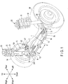
- FIG. 1 is a perspective view showing an example of the stabilizer 1 in a state of being mounted on a vehicle.
- the stabilizer (stabilizer bar) 1 is formed by bending a bar of spring steel into a U-shape.
- the steel type of the stabilizer 1 is not limited to only spring steel, but may be high strength steel or steel for carburization.
- the stabilizer 1 is covered with a coating film 5 such as an epoxy-based paint containing a corrosion-resistant component.
- the stabilizer 1 includes a torsion portion 2, a pair of arm portions 3 and 4, and a restriction ring 10.
- the torsion portion 2 is formed in a substantially linear shape extending in the vehicle width direction (right and left direction) of the vehicle.
- the pair of arm portions 3 and 4 extend from both ends 2L and 2R of the torsion portion 2 toward right and left wheels W, respectively. Eyes 3E and 4E are formed at distal ends of the arms 3 and 4, respectively.
- Suspension units IS are attached to the right and left wheels W, respectively.
- the suspension device IS comprises, for example, a spring S, a damper D, and a stabilizer link L.
- the spring S and the damper D support the wheel W.
- a proximal end Lp of the stabilizer link L is attached to the damper D.
- the stabilizer link L is inclined with respect to the expansion and contraction direction P of the spring S and, when the spring S expands and contracts, the distal end Ld of the stabilization link L rocks in a direction Q different from the expansion and contraction direction P of the spring S.
- the torsion portion 2 of the stabilizer 1 is suspended from the vehicle body via a cylindrical bush (bearing cylinder) B.
- the torsion portion 2 is not completely fixed to the bush B, but can rotate in the circumferential direction Y to generate a torsional stress.
- the pair of arms 3 and 4 are connected to the distal ends Ld of the stabilizer links L of the suspension units IS by the eyes 3E and 4E.
- the restriction ring 10 that restricts the movement of the torsion portion 2 is coupled to the torsion portion.
- the restriction ring 10 is coupled to the coupling site 2B adjacent to the bush B and, when the component load is input to the stabilizer 1, the restriction ring 10 abuts on the bush B to prevent the movement of the torsion portion 2 in the axial direction X.
- the axial direction X of the torsion portion 2 coincides with the width direction of the vehicle.
- the restriction ring 10 may be adjacent to the bush B from the inside in the axial direction X or may be adjacent from the outside.
- FIG. 2 is an enlarged perspective view of the restriction ring 10 shown in FIG. 1 .
- the restriction ring 10 includes a main body 11, a male portion 12, a female portion 13, and a weld portion 14.
- the restriction ring 10 further includes thick portions 15 and 16 and a surrounding portion 17.
- the main body 11 is formed in a strip shape extending in the circumferential direction Y of the torsion portion 2.
- the male portion (first locking portion) 12 is formed at one end 11A of the main body 11.
- the female portion (second locking portion) 13 is formed on the other end 11B of the main body 11 and is locked to the male portion 12.
- the weld portion 14 is formed of the same type of metal material as the male portion 12 and the female portion 13, in a substantially circular shape, and welds the male portion 12 and the female portion 13.
- the thick portions 15 and 16 are formed to be thicker by 0.5 mm or more than the other parts of the restriction ring 10.
- the thick portion 15 is formed in a strip shape crossing the male portion 12 and the female portion 13 in the width direction of the restriction ring 10.
- the width direction of the restriction ring coincides with the axial direction X of the torsion portion 2 and the vehicle width direction of the vehicle.
- the thick portion 16 is formed on a side opposite to the thick portion 15 at 180°, in the circumferential direction Y.
- the surrounding portion 17 is provided across the one end 11A and the other end 11B of the main body 11, and surrounds the weld portion 14. In the surrounding portion 17, the outer peripheral surface 10A and the side surface 10C of the restriction ring 10 are exposed from the weld portion 14.
- the surrounding portion 17 includes a male side surrounding portion 17M provided at one end 11A of the main body 11, and a female side surrounding portion 17F provided at the other end 11B.
- the male side surrounding portion 17M is formed integrally with the male portion 12.
- the female side surrounding portion 17F is formed integrally with the female portion 13.
- the male side surrounding portion 17M and the female side surrounding portion 17F are flush with each other in the axial direction X of the torsion portion 2.
- the weld portion 14 is eliminated. That is, in the male portion 12 and the female portion 13, the side surface 10C formed by the male side surrounding portion 17M and the female side surrounding portion 17F is formed to be flat.
- the side surface 10C of the restriction ring 10 abuts on the bush B when the component load is input to the torsion portion 2.
- FIG. 3 is an enlarged side view showing the male portion 12 and the female portion 13 of the restriction ring 10.
- the female portion 13 is formed in a concave shape opened toward the male portion 12 and includes a valley bottom portion 31 and a pair of sandwiching portions 32 and 33.
- the valley bottom portion 31 constitutes the bottom of the female portion 13 at the other end 11B of the main body 11.
- the pair of sandwiching portions 32 and 33 are arranged and spaced apart from each other at an interval OP in the width direction (axial direction X) of the restriction ring 10.
- the interval OP in the axial direction X becomes narrower.
- the direction from the top to the bottom in FIG. 3 is the direction in which the sandwiching portions are located farther from the valley bottom portion 31.
- the direction from the top to the bottom in FIG. 3 may be rephrased as the direction from the one end 11A to the other end 11B in the main body 11 or the direction from the main body 11 to the female portion 13.
- Distal ends 32D and 33D of the pair of sandwiching portions 32 and 33 constitute a path having a narrower interval OP than the other parts of the female portion 13.
- the male portion 12 is formed in a convex shape protruding toward the female portion 13 and includes a neck portion 21, an expanding portion 22, a contracting portion 23, and guide portions 24 and 25.
- the neck portion 21 extends from one end 11A of the main body 11 and is formed to be narrower than the main body 11.
- the neck portion 21 is inserted between the distal ends 32D and 33D of the pair of sandwiching portions 32 and 33.
- the expanding portion 22 becomes larger in the width direction (axial direction X) of the restriction ring 10 as the portion is located farther from the neck portion 21.
- the contracting portion 23 becomes smaller in the width direction of the restriction ring 10 as the portion is located farther from the neck portion 21.
- the direction from the bottom to the top in FIG. 3 is the direction of being located farther from the neck portion 21.
- the direction from the bottom to the top in FIG. 3 may be rephrased as the direction from the other end 11B to the one end 11A in the main body 11 or the direction from the main body 11 to the male portion 12.
- the contracting portion 23 is formed in a semicircular shape.
- the expanding portion 22 is formed in a semicircular shape except for a portion connected to the neck portion 21.
- the guide portions (shoulders) 24 and 25 are provided on both sides of the neck portion 21, respectively, in the width direction of the restriction ring 10 so as to sandwich the neck portion 21.
- the guide portions 24 and 25 are formed with inclined surfaces that are closer to the neck portion 21 from the male portion 12 toward the main body 11.
- the weld portion 14 covers at least the range of the contracting portion 23 of the male portion 12 and the valley bottom portion 31 of the female portion 13 as viewed from the outer peripheral surface 10A of the restriction ring 10.
- the weld portion 14 covers the contracting portion 23, the expanding portion 22, and the neck portion 21 of the male portion 12, and the valley bottom portion 31 and the distal ends 32D and 33D of the holding portions 32 and 33, of the female portion 13.
- the weld portion 14 has a circular shape as viewed from the outer peripheral surface 10A of the restriction ring 10.
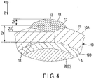
- FIG. 4 is a sectional view taken along line F4-F4 of FIG. 3 .
- the weld portion 14 is melted in the thickness direction Z from the outer peripheral surface 10A of the restriction ring 10 to integrate the contracting portion 23 of the male portion 12 and the valley bottom portion 31 of the female portion 13.
- a thickness of the restriction ring 10 at a part different from the thick portions 15 and 16 is referred to as Zt.
- the height Zh of the weld portion 14 is, for example, 1/2 or less of the thickness Zt of the restriction ring 10.
- An uneven pattern 18 harder than the coating film 5 of the torsion portion 2 is formed on the inner peripheral surface 10B of the restriction ring 10, and the uneven pattern 18 matches the coating film 5.
- the uneven pattern 18 can be formed, for example, by knurling.
- the coating film 5 of the coupling site 2B to which the restriction ring 10 is coupled may be formed to be thicker than the coating film 5 of the eyes 3E and 4E.
- the coating film 5 can be formed by, for example, powder baking finish.
- the thickness of the coating film 5 can be adjusted in accordance with, for example, the coating time or the number of times of coating.
- the restriction ring 10 is formed of, for example, a metal material such as aluminum or an aluminum alloy, and is attached to the torsion portion 2 later.
- the restriction ring 10 in a state before being coupled to the torsion portion 2 is formed in a band shape curved in a C letter.
- the interval OP between the pair of sandwiching portions 32 and 33 shown in FIG. 4 is constant, and the distal ends 32D and 33D are not narrow paths.
- the manufacturing method for manufacturing the stabilizer 1 of the present embodiment comprises a preparation step, a caulking step, and a welding step.
- the preparation step the main body 11 of the restriction ring 10 is disposed so as to be wound around the torsion portion 2.
- the caulking step the female portion 13 is pressed against the male portion 12 to plastically deform the sandwiching portions 32 and 33 of the female portion 13 into a shape that follows the expanding portion 22 of the male portion 12.
- the pair of sandwiching portions 32 and 33 are guided by the inclined surfaces of the guide portions 24 and 25 and deform toward the neck portion 21. Eventually, the pair of sandwiching portions 32 and 33 are formed in a shape that follows the expanding portion 22, and the female portion 13 is engaged with the male portion 12. In the welding step, the male portion 12 and the female portion 13 are welded to form the weld portion 14 shown in FIG. 2 and FIG. 3 .
- a small gap may occur between the contracting portion 23 and the valley bottom portion 31 due to spring back as shown in FIG. 3 . That is, in the restriction ring 10 formed in the caulking step, the contracting portion 23 and the valley bottom portion 31 are cut, and the contracting portion 23 does not contribute to the coupling force of the restriction ring 10.
- the manufacturing method according to the present embodiment includes the welding step after the caulking step.
- the welding step as shown in FIG. 3 and FIG. 4 , the weld portion 14 in which the contracting portion 23 and the valley bottom portion 31 are integrated is formed.
- the restriction ring 10 having undergone the welding step further has an engagement between the contracting portion 23 and the valley bottom portion 31.
- first to seventh examples and first and second comparative examples of forming the weld portion 14 of various shapes in the welding step will be explained hereinafter with reference to FIG. 5 to FIG. 13 .
- All of the first to seventh examples and the first and second comparative examples are common with respect to a feature of forming the contracting portion 23 having a diameter of 5 mm on the restriction ring 10 having a width of 14 mm and a thickness Zt of 4.2 mm.
- the range indicated by oblique lines upward to the right in FIG. 5 to FIG. 8 corresponds to the thick portion 15 and is formed to be thicker than the thickness Zt by 0.5 mm or more.
- the weld portion 14 having a diameter of 10 mm and a height Zh of 2 mm was formed at the center of the male portion 12.
- the center 14X of the weld portion 14 overlaps the thick portion 15.
- the weld portion 14 having a diameter of 10 mm and a height Zh of 2 mm is formed to be shifted in the width direction as compared with the first example.
- the weld portion 14 having a diameter of 10 mm and a height Zh of 2 mm was formed to be shifted toward the side of the contracting portion 23 of the male portion 12 as compared with the first example.
- the center 14X of the weld portion 14 is excluded from the range of the thick portion 15.
- the weld portion 14 having a diameter of 10 mm and a height Zh of 2 mm is formed to be shifted toward the side of the expanded portion 22 of the male portion 12 as compared with the first example.
- the center 14X of the weld portion 14 is excluded from the range of the thick portion 15.
- the weld portion 14 having a diameter of 8 mm and a height Zh of 2 mm was formed.
- the height Zh of the weld portion 14 is half or less of the thickness Zt of the restriction ring 10.
- the weld portion 14 having a diameter of 8 mm and a height Zh of 2 mm is formed to be shifted in the width direction as compared with the fifth example.
- the height Zh of the weld portion 14 is half or less of the thickness Zt of the restriction ring 10.
- the weld portion 14 having a diameter of 7 mm and a height Zh of 3 mm was formed.
- the height Zh of the weld portion 14 exceeds one half of the thickness Zt of the restriction ring 10.
- the weld portion 14 having a diameter of 5 mm was formed.
- the weld portion 14 was not formed.
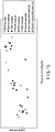
- FIG. 13 is a graph showing a coupling force of the restriction ring 10 measured for the first to seventh examples and the first and second comparative examples.
- the coupling site 2B to which the restriction ring 10 is coupled and its vicinity are cut out as a test piece, and a jig having the same shape as the bush B is pressed against the restriction ring 10 to measure the load when the restriction ring 10 is broken.
- the coupling force of the restriction ring 10 increases. Comparing the same thickness, the coupling force of the restriction ring 10 was increased in order of the first example > the second example > the third example > the fourth example > the fifth example > the sixth example > the seventh example > the first comparative example > the second comparative example.
- Comparison between the measurement results (first and second examples) in which the center 14X of the weld portion 14 overlaps the range of the thick portion 15 and the measurement results (third and fourth examples) in which the center 14X of the weld portion 14 is excluded from the range of the thick portion 15 indicates that the coupling force tends to decrease at the restriction ring 10 in which the center 14X of the weld portion 14 is excluded from the range of the thick portion 15.
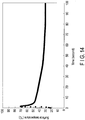
- FIG. 14 is a graph showing an example of a surface temperature of torsion portion 2 in a welding process measured on the back side of the weld portion 14. As shown in FIG. 14 , the temperatures of the torsion portion 2 and the restriction ring 10 instantaneously rise in the welding step. After that, the cooled restriction ring 10 contracts and engages with the coating film 5 of the bonding site 2B.
- the male portion 12 and the female portion 13 are further firmly engaged with each other by the contraction of the cooled restriction ring 10.
- the surface temperature of the torsion portion 2 is, for example, 80°C or less, which is much lower than the tempering temperature of the spring steel of the torsion portion 2 and the baking temperature of the coating film 5.
- the contracting portion 23 and the valley bottom portion 31 which have not contributed to the coupling force are integrated by the weld portion 14.
- the present embodiment can be configured such that not only the engagement between the expanding portion 22 and the pair of sandwiching portions 32 and 33, but the engagement between the contracting portion 23 and the valley bottom portion 31 contribute to the coupling force of the restriction ring 10.
- the restriction ring 10 can bear a large component load, and the displacement of the torsion portion 2 in the axial direction X can be prevented more reliably.
- the restriction ring 10 can be applied to the stabilizer 1 having a large rigidity, to which the restriction ring 10 cannot be applied so far, and the displacement of the torsion portion 2 in the axial direction X can be prevented in a wider range of vehicle type.
- the torsion portion 2 If the torsion portion 2 is completely fixed to the bush B for the purpose of preventing the movement of the torsion portion 2 in the axial direction X, the torsion portion 2 cannot rotate and the spring characteristics of the stabilizer 1 will change.
- the coupling force of the restriction ring 10 with respect to the torsion portion 2 can be improved while making use of the excellent merits of the restriction ring 10.
- the height Zh of the weld portion 14 is preferably 1/2 or less of the thickness Zt. If the height Zh of the weld portion 14 is 1/2 or less of the thickness Zt, the weld portion 14 melts to a sufficient depth Zd in the thickness direction Z, and the contracting portion 23 and the valley bottom portion 31 can be thereby integrated firmly. In addition, interference between the restriction ring 10 and the other parts can be prevented by setting the height Zh of the weld portion 14 to 1/2 or less of the thickness Zt. Furthermore, since the height Zh of the weld portion 14 is used as an index, the amount of penetration of the weld portion 14 can be managed easily, and affecting the coating film of the stabilizer 1 due to excessive heat input during welding can be prevented effectively.
- the present embodiment includes a band-like thick portion 15 which crosses the male portion 12 and the female portion 13. If the center 14X of the weld portion 14 is disposed so as to overlap the thick portion 15, the weld portion 14 can be formed so as to cover the entire male portion 12 with the weld portion 14 spreading from the thick portion 15. Since the weld portion 14 which covers not only the contracting portion 23 and the valley bottom portion 31, but the entire boundary between the male portion 12 and the female portion 13 can be formed, the restriction ring 10 can be coupled firmly.
- the present embodiment includes a surrounding portion 17 from which the weld portion 14 is eliminated.
- the surrounding portion 17 is formed across the male portion 12 and the female portion 13, and is formed such that its side surface 10C is flush with the male portion 12 and the female portion 13. According to the present embodiment, when the side surface 10C abuts on the bush B, the side surface 10C can be configured flat such that excessive load is not concentrated on the male portion 12 and the female portion 13. Furthermore, the influence of the heat input at the time of welding can be relaxed, and structural changes other than the weld portion 14 can be prevented in the restriction ring 10, by providing the surrounding portion 17.
- valley bottom portion 32, 33... sandwiching portion, 32D, 33D... distal end of sandwiching portion, B... bush, IS... suspension unit, OP... interval of a pair of sandwiching portions, W... wheel, X... axial direction of torsion portion, Z... thickness direction of the regulation ring, Zh ...height of weld portion, Zt... thickness of regulation ring.
Landscapes
- Engineering & Computer Science (AREA)
- General Engineering & Computer Science (AREA)
- Mechanical Engineering (AREA)
- Vehicle Body Suspensions (AREA)
- Springs (AREA)
- Standing Axle, Rod, Or Tube Structures Coupled By Welding, Adhesion, Or Deposition (AREA)
Abstract
Description
- The present invention relates generally to a stabilizer for vehicle comprising a restriction ring that restricts movement in an axial direction, and a method of manufacturing the stabilizer.
- A vehicle such as an automobile comprises a stabilizer that interlocks suspension units of right and left wheels to suppress rolling of the vehicle body and improve traveling stability. The stabilizer is a rod member of spring steel bent in a U-letter shape, and comprises a torsion portion suspended from a bottom surface of the vehicle body via a cylindrical bush, and a pair of arm portions attached to stabilizer links of the suspension units.
- When the vehicle turns, the spring of the suspension unit on the outer wheel side is compressed by the centrifugal force, and the spring of the suspension unit on the inner wheel side is extended. At this time, an arm attached to the outer wheel side is pushed upward, and an arm attached to the inner wheel side is pushed downward. The torsion portion is not completely fixed to the bush, but rotates in the circumferential direction Y to generate a torsional stress. The restoring force of the twisted torsion portion acts in the direction in which the vehicle is in a horizontal position to suppress the rolling of the vehicle body.
- However, the stabilizer link is attached obliquely to the extending and contracting direction of the spring. When the spring extends and contracts, not only a load that twists the torsion portion in the circumferential direction, but also a component load that attempts to move the torsion portion in the axial direction are input to the stabilizer. If the position of the stabilizer is shifted in the axial direction, the stabilizer interferes with the accessory of the vehicle to generate noise. In addition, the spring characteristics of the stabilizer may change to change the ride quality of the vehicle.
- A stabilizer provided with a restriction ring that abuts on the bush and restricts the movement of the torsion portion to prevent displacement of the stabilizer, has been proposed (for example, see Patent Literatures 1 and 2). However, when the weight of the vehicle increases, the component load for moving the torsion portion in the axial direction increases. If the restriction ring is applied to a stabilizer mounted on a large vehicle, the restriction ring cannot withstand the component load and may fall off.
-
- Patent Literature 1:
JP 2015-151083 A - Patent Literature 2:
JP 2005-271886 A - Embodiments described herein aim to provide a stabilizer comprising a restriction ring that can withstand a large component load and capable of preventing axial displacement, and a method of manufacturing the same.
- A stabilizer according to one of the embodiments is provided at a vehicle, and comprises a torsion portion, a pair of arms, and a restriction ring. The torsion portion is suspended from the vehicle body via a bush. The pair of arms extend from both ends of the torsion portion toward right and left wheels, respectively, and are attached to a suspension unit. The restriction ring is coupled to the torsion portion at a location adjacent to the bush. The restriction ring includes a main body, a female portion, a male portion, and a weld portion. The main body is formed in a band shape. The female portion includes a valley bottom portion and a pair of sandwiching portions. The valley bottom portion is located at one end of the main body. The pair of sandwiching portions are spaced apart from each other in the axial direction of the torsion portion, and the distance becomes narrower as the distance from the valley bottom portion increases. The male portion includes a neck, an expanding portion, and a contracting portion. The neck extends from the other end of the main body, and is inserted between distal ends of the pair of sandwiching portions. The expanding portion becomes larger in the axial direction of the torsion portion as the portion is farther from the neck. The contracting portion becomes smaller in the axial direction of the torsion part as the portion is farther from the neck. At the weld portion, the male portion and the female portion are welded. The weld portion covers at least the range of the contracting portion and the valley bottom portion as viewed from the outer peripheral surface of the restriction ring, and is melted in the thickness direction from the outer peripheral surface to integrate the contracting portion and the valley bottom portion.
- A stabilizer manufacturing method according to one of the embodiments comprises a preparation step, a caulking step, and a welding step. In the preparation step, the main body is arranged to be wound around the torsion portion. In the caulking step, the female portion is pressed against the male portion, and the pair of sandwiching portions are plastically deformed into a shape that follows the expanding portion. In the welding step, welding is performed so as to cover at least the range of the contracting portion and the valley bottom portion as viewed from the outer peripheral surface of the restriction ring. The weld portion that is welded in the thickness direction from the outer peripheral surface to integrate the contracting portion and the valley bottom portion is thereby formed.
-
-
FIG. 1 is a perspective view showing an example of a stabilizer according to an embodiment in a state of being mounted on a vehicle. -
FIG. 2 is an enlarged perspective view of a restriction ring shown inFIG. 1 . -
FIG. 3 is an enlarged side view showing a male portion and a female portion shown inFIG. 2 . -
FIG. 4 is a cross-sectional view taken along line F4-F4 inFIG. 3 . -
FIG. 5 is a side view showing a first example in which a weld portion having a diameter of 10 mm is formed at the center of a male portion. -
FIG. 6 is a side view showing a second example in which a weld portion having a diameter of 10 mm is formed to be shifted in the width direction as compared with the first example. -
FIG. 7 is a side view showing a third example in which a weld portion having a diameter of 10 mm is formed to be shifted to the contracting portion side as compared with the first example. -
FIG. 8 is a side view showing a fourth example in which a weld portion having a diameter of 10 mm is formed to be shifted to an expanding portion side as compared with the first example. -
FIG. 9 is a side view showing a fifth example in which a weld portion having a diameter of 8 mm is formed at the center of a male portion. -
FIG. 10 is a side view showing a sixth example in which a weld portion having a diameter of 8 mm is formed to be shifted in the width direction as compared with the fifth example. -
FIG. 11 is a side view showing a seventh example in which a weld portion having a diameter of 7 mm is formed. -
FIG. 12 is a side view showing a first comparative example in which a weld portion having a diameter of 5 mm is formed. -
FIG. 13 is a graph showing a coupling force of a restriction ring measured for each example and comparative example. -
FIG. 14 is a graph showing an example of a surface temperature of a torsion portion in a welding process measured on the back side of the weld portion. - A stabilizer 1 according to one of embodiments of the present invention will be explained hereinafter with reference to
FIG. 1 to FIG. 14 .FIG. 1 is a perspective view showing an example of the stabilizer 1 in a state of being mounted on a vehicle. The stabilizer (stabilizer bar) 1 is formed by bending a bar of spring steel into a U-shape. - Examples of the steel type are, for example, SAE10B21, SAE15B26, SAE5160, etc., conforming to the regulations of the American Association of Automotive Engineers or, for example, SUP9, etc., conforming to JIS or, for example, 26MnB5, 34MnB5, etc. The steel type of the stabilizer 1 is not limited to only spring steel, but may be high strength steel or steel for carburization. The stabilizer 1 is covered with a
coating film 5 such as an epoxy-based paint containing a corrosion-resistant component. - The stabilizer 1 includes a
torsion portion 2, a pair ofarm portions 3 and 4, and arestriction ring 10. Thetorsion portion 2 is formed in a substantially linear shape extending in the vehicle width direction (right and left direction) of the vehicle. The pair ofarm portions 3 and 4 extend from both ends 2L and 2R of thetorsion portion 2 toward right and left wheels W, respectively.Eyes arms 3 and 4, respectively. - Suspension units IS are attached to the right and left wheels W, respectively. The suspension device IS comprises, for example, a spring S, a damper D, and a stabilizer link L. The spring S and the damper D support the wheel W. A proximal end Lp of the stabilizer link L is attached to the damper D. The stabilizer link L is inclined with respect to the expansion and contraction direction P of the spring S and, when the spring S expands and contracts, the distal end Ld of the stabilization link L rocks in a direction Q different from the expansion and contraction direction P of the spring S.
- The
torsion portion 2 of the stabilizer 1 is suspended from the vehicle body via a cylindrical bush (bearing cylinder) B. Thetorsion portion 2 is not completely fixed to the bush B, but can rotate in the circumferential direction Y to generate a torsional stress. The pair ofarms 3 and 4 are connected to the distal ends Ld of the stabilizer links L of the suspension units IS by theeyes - The
restriction ring 10 that restricts the movement of thetorsion portion 2 is coupled to the torsion portion. Therestriction ring 10 is coupled to thecoupling site 2B adjacent to the bush B and, when the component load is input to the stabilizer 1, therestriction ring 10 abuts on the bush B to prevent the movement of thetorsion portion 2 in the axial direction X. The axial direction X of thetorsion portion 2 coincides with the width direction of the vehicle. Therestriction ring 10 may be adjacent to the bush B from the inside in the axial direction X or may be adjacent from the outside. -
FIG. 2 is an enlarged perspective view of therestriction ring 10 shown inFIG. 1 . As shown inFIG. 2 , therestriction ring 10 includes amain body 11, amale portion 12, afemale portion 13, and aweld portion 14. In the example shown inFIG. 2 , therestriction ring 10 further includesthick portions portion 17. - The
main body 11 is formed in a strip shape extending in the circumferential direction Y of thetorsion portion 2. The male portion (first locking portion) 12 is formed at oneend 11A of themain body 11. The female portion (second locking portion) 13 is formed on theother end 11B of themain body 11 and is locked to themale portion 12. Theweld portion 14 is formed of the same type of metal material as themale portion 12 and thefemale portion 13, in a substantially circular shape, and welds themale portion 12 and thefemale portion 13. - The
thick portions restriction ring 10. Thethick portion 15 is formed in a strip shape crossing themale portion 12 and thefemale portion 13 in the width direction of therestriction ring 10. The width direction of the restriction ring coincides with the axial direction X of thetorsion portion 2 and the vehicle width direction of the vehicle. Thethick portion 16 is formed on a side opposite to thethick portion 15 at 180°, in the circumferential direction Y. - The surrounding
portion 17 is provided across the oneend 11A and theother end 11B of themain body 11, and surrounds theweld portion 14. In the surroundingportion 17, the outerperipheral surface 10A and theside surface 10C of therestriction ring 10 are exposed from theweld portion 14. The surroundingportion 17 includes a maleside surrounding portion 17M provided at oneend 11A of themain body 11, and a femaleside surrounding portion 17F provided at theother end 11B. The maleside surrounding portion 17M is formed integrally with themale portion 12. The femaleside surrounding portion 17F is formed integrally with thefemale portion 13. - The male
side surrounding portion 17M and the femaleside surrounding portion 17F are flush with each other in the axial direction X of thetorsion portion 2. In the surroundingportion 17, theweld portion 14 is eliminated. That is, in themale portion 12 and thefemale portion 13, theside surface 10C formed by the maleside surrounding portion 17M and the femaleside surrounding portion 17F is formed to be flat. Theside surface 10C of therestriction ring 10 abuts on the bush B when the component load is input to thetorsion portion 2. -
FIG. 3 is an enlarged side view showing themale portion 12 and thefemale portion 13 of therestriction ring 10. As shown inFIG. 3 , thefemale portion 13 is formed in a concave shape opened toward themale portion 12 and includes avalley bottom portion 31 and a pair of sandwichingportions valley bottom portion 31 constitutes the bottom of thefemale portion 13 at theother end 11B of themain body 11.
The pair of sandwichingportions restriction ring 10. - As the pair of sandwiching
portions valley bottom portion 31 in the circumferential direction Y, the interval OP in the axial direction X becomes narrower. The direction from the top to the bottom inFIG. 3 is the direction in which the sandwiching portions are located farther from thevalley bottom portion 31. The direction from the top to the bottom inFIG. 3 may be rephrased as the direction from the oneend 11A to theother end 11B in themain body 11 or the direction from themain body 11 to thefemale portion 13. Distal ends 32D and 33D of the pair of sandwichingportions female portion 13. - The
male portion 12 is formed in a convex shape protruding toward thefemale portion 13 and includes aneck portion 21, an expandingportion 22, acontracting portion 23, and guideportions neck portion 21 extends from oneend 11A of themain body 11 and is formed to be narrower than themain body 11. Theneck portion 21 is inserted between the distal ends 32D and 33D of the pair of sandwichingportions - The expanding
portion 22 becomes larger in the width direction (axial direction X) of therestriction ring 10 as the portion is located farther from theneck portion 21. Thecontracting portion 23 becomes smaller in the width direction of therestriction ring 10 as the portion is located farther from theneck portion 21. The direction from the bottom to the top inFIG. 3 is the direction of being located farther from theneck portion 21. The direction from the bottom to the top inFIG. 3 may be rephrased as the direction from theother end 11B to the oneend 11A in themain body 11 or the direction from themain body 11 to themale portion 12. - In the example shown in
FIG. 3 , thecontracting portion 23 is formed in a semicircular shape. The expandingportion 22 is formed in a semicircular shape except for a portion connected to theneck portion 21. The guide portions (shoulders) 24 and 25 are provided on both sides of theneck portion 21, respectively, in the width direction of therestriction ring 10 so as to sandwich theneck portion 21. Theguide portions neck portion 21 from themale portion 12 toward themain body 11. - The
weld portion 14 covers at least the range of thecontracting portion 23 of themale portion 12 and thevalley bottom portion 31 of thefemale portion 13 as viewed from the outerperipheral surface 10A of therestriction ring 10. In the example shown inFIG. 3 , theweld portion 14 covers thecontracting portion 23, the expandingportion 22, and theneck portion 21 of themale portion 12, and thevalley bottom portion 31 and the distal ends 32D and 33D of the holdingportions female portion 13. Furthermore, theweld portion 14 has a circular shape as viewed from the outerperipheral surface 10A of therestriction ring 10. -
FIG. 4 is a sectional view taken along line F4-F4 ofFIG. 3 . As shown inFIG. 4 , theweld portion 14 is melted in the thickness direction Z from the outerperipheral surface 10A of therestriction ring 10 to integrate thecontracting portion 23 of themale portion 12 and thevalley bottom portion 31 of thefemale portion 13. A thickness of therestriction ring 10 at a part different from thethick portions weld portion 14 is, for example, 1/2 or less of the thickness Zt of therestriction ring 10. - An
uneven pattern 18 harder than thecoating film 5 of thetorsion portion 2 is formed on the innerperipheral surface 10B of therestriction ring 10, and theuneven pattern 18 matches thecoating film 5. Theuneven pattern 18 can be formed, for example, by knurling. Thecoating film 5 of thecoupling site 2B to which therestriction ring 10 is coupled may be formed to be thicker than thecoating film 5 of theeyes coating film 5 can be formed by, for example, powder baking finish. The thickness of thecoating film 5 can be adjusted in accordance with, for example, the coating time or the number of times of coating. - The
restriction ring 10 is formed of, for example, a metal material such as aluminum or an aluminum alloy, and is attached to thetorsion portion 2 later. Therestriction ring 10 in a state before being coupled to thetorsion portion 2 is formed in a band shape curved in a C letter. In therestriction ring 10 in this state, the interval OP between the pair of sandwichingportions FIG. 4 is constant, and the distal ends 32D and 33D are not narrow paths. - The manufacturing method for manufacturing the stabilizer 1 of the present embodiment comprises a preparation step, a caulking step, and a welding step. In the preparation step, the
main body 11 of therestriction ring 10 is disposed so as to be wound around thetorsion portion 2. In the caulking step, thefemale portion 13 is pressed against themale portion 12 to plastically deform the sandwichingportions female portion 13 into a shape that follows the expandingportion 22 of themale portion 12. - When the
female portion 13 is pressed against themale portion 12, the pair of sandwichingportions guide portions neck portion 21. Eventually, the pair of sandwichingportions portion 22, and thefemale portion 13 is engaged with themale portion 12. In the welding step, themale portion 12 and thefemale portion 13 are welded to form theweld portion 14 shown inFIG. 2 andFIG. 3 . - At this time, a small gap may occur between the contracting
portion 23 and thevalley bottom portion 31 due to spring back as shown inFIG. 3 . That is, in therestriction ring 10 formed in the caulking step, thecontracting portion 23 and thevalley bottom portion 31 are cut, and thecontracting portion 23 does not contribute to the coupling force of therestriction ring 10. - However, the manufacturing method according to the present embodiment includes the welding step after the caulking step. In the welding step, as shown in
FIG. 3 andFIG. 4 , theweld portion 14 in which thecontracting portion 23 and thevalley bottom portion 31 are integrated is formed. In addition to the engagement between the expandingportion 22 and the pair of sandwichingportions restriction ring 10 having undergone the welding step further has an engagement between the contractingportion 23 and thevalley bottom portion 31. - First to seventh examples and first and second comparative examples of forming the
weld portion 14 of various shapes in the welding step will be explained hereinafter with reference toFIG. 5 to FIG. 13 . All of the first to seventh examples and the first and second comparative examples are common with respect to a feature of forming thecontracting portion 23 having a diameter of 5 mm on therestriction ring 10 having a width of 14 mm and a thickness Zt of 4.2 mm. The range indicated by oblique lines upward to the right inFIG. 5 to FIG. 8 corresponds to thethick portion 15 and is formed to be thicker than the thickness Zt by 0.5 mm or more. - In the first example, as shown in
FIG. 5 , theweld portion 14 having a diameter of 10 mm and a height Zh of 2 mm was formed at the center of themale portion 12. Thecenter 14X of theweld portion 14 overlaps thethick portion 15. - In the second example, as shown in
FIG. 6 , theweld portion 14 having a diameter of 10 mm and a height Zh of 2 mm is formed to be shifted in the width direction as compared with the first example. Thecenter 14X of theweld portion 14 overlaps thethick portion 15. - In the third example, as shown in
FIG. 7 , theweld portion 14 having a diameter of 10 mm and a height Zh of 2 mm was formed to be shifted toward the side of thecontracting portion 23 of themale portion 12 as compared with the first example. Thecenter 14X of theweld portion 14 is excluded from the range of thethick portion 15. - In the fourth example, as shown in
FIG. 8 , theweld portion 14 having a diameter of 10 mm and a height Zh of 2 mm is formed to be shifted toward the side of the expandedportion 22 of themale portion 12 as compared with the first example. Thecenter 14X of theweld portion 14 is excluded from the range of thethick portion 15. - In the fifth example, as shown in
FIG. 9 , theweld portion 14 having a diameter of 8 mm and a height Zh of 2 mm was formed. The height Zh of theweld portion 14 is half or less of the thickness Zt of therestriction ring 10. - In the sixth example, as shown in
FIG. 10 , theweld portion 14 having a diameter of 8 mm and a height Zh of 2 mm is formed to be shifted in the width direction as compared with the fifth example. The height Zh of theweld portion 14 is half or less of the thickness Zt of therestriction ring 10. - In the seventh example, as shown in
FIG. 11 , theweld portion 14 having a diameter of 7 mm and a height Zh of 3 mm was formed. The height Zh of theweld portion 14 exceeds one half of the thickness Zt of therestriction ring 10. - In the first comparative example, as shown in
FIG. 12 , theweld portion 14 having a diameter of 5 mm was formed. - In the second comparative example, the
weld portion 14 was not formed. -
FIG. 13 is a graph showing a coupling force of therestriction ring 10 measured for the first to seventh examples and the first and second comparative examples. Thecoupling site 2B to which therestriction ring 10 is coupled and its vicinity are cut out as a test piece, and a jig having the same shape as the bush B is pressed against therestriction ring 10 to measure the load when therestriction ring 10 is broken. - As shown in
FIG. 13 , as the thickness of thecoating film 5 at thecoupling site 2B is larger, the coupling force of therestriction ring 10 increases. Comparing the same thickness, the coupling force of therestriction ring 10 was increased in order of the first example > the second example > the third example > the fourth example > the fifth example > the sixth example > the seventh example > the first comparative example > the second comparative example. - Comparison between the measurement results (first and second examples) in which the
center 14X of theweld portion 14 overlaps the range of thethick portion 15 and the measurement results (third and fourth examples) in which thecenter 14X of theweld portion 14 is excluded from the range of thethick portion 15 indicates that the coupling force tends to decrease at therestriction ring 10 in which thecenter 14X of theweld portion 14 is excluded from the range of thethick portion 15. - Furthermore, comparison between the third and fourth examples in which the
center 14X of theweld portion 14 is excluded from the range of thethick portion 15 indicates that the third example in which the center is shifted from the thick portion 1 5 to thecontracting portion 23 side was not substantially different from the first or second example. In contrast, in the fourth example in which the center is shifted from thethick portion 15 to the expandingportion 22 side, the coupling force is much lower than that in the first to third examples. It can be understood that theweld portion 14 covering thecontracting portion 23 largely contributes to the coupling force. - In addition, comparison between the measurement results (fifth and sixth examples) in which the height Zh of the
weld portion 14 was half or less of the thickness Zt of therestriction ring 10 and the height Zh of theweld portion 14 of therestriction ring 10 and the measurement result (seventh example) in which the height Zh of theweld portion 14 exceeded 1/2 of the thickness Zt of therestriction ring 10 indicates that the coupling force tended to decrease in theregulation ring 10 in which the height Zh of theweld portion 14 exceeded 1/2 of the thickness Zt of therestriction ring 10. -
FIG. 14 is a graph showing an example of a surface temperature oftorsion portion 2 in a welding process measured on the back side of theweld portion 14. As shown inFIG. 14 , the temperatures of thetorsion portion 2 and therestriction ring 10 instantaneously rise in the welding step. After that, the cooledrestriction ring 10 contracts and engages with thecoating film 5 of thebonding site 2B. - In addition, in the sites which are not integrated by welding, of the
male portion 12 and thefemale portion 13, themale portion 12 and thefemale portion 13 are further firmly engaged with each other by the contraction of the cooledrestriction ring 10. The surface temperature of thetorsion portion 2 is, for example, 80°C or less, which is much lower than the tempering temperature of the spring steel of thetorsion portion 2 and the baking temperature of thecoating film 5. - In the stabilizer 1 of the present embodiment configured as described above, the
contracting portion 23 and thevalley bottom portion 31 which have not contributed to the coupling force are integrated by theweld portion 14. The present embodiment can be configured such that not only the engagement between the expandingportion 22 and the pair of sandwichingportions portion 23 and thevalley bottom portion 31 contribute to the coupling force of therestriction ring 10. - As a result, the
restriction ring 10 can bear a large component load, and the displacement of thetorsion portion 2 in the axial direction X can be prevented more reliably. In addition, therestriction ring 10 can be applied to the stabilizer 1 having a large rigidity, to which therestriction ring 10 cannot be applied so far, and the displacement of thetorsion portion 2 in the axial direction X can be prevented in a wider range of vehicle type. - If the
torsion portion 2 is completely fixed to the bush B for the purpose of preventing the movement of thetorsion portion 2 in the axial direction X, thetorsion portion 2 cannot rotate and the spring characteristics of the stabilizer 1 will change. - If a thrust load is applied to cause plastic deformation such that the
torsion portion 2 itself becomes locally large in diameter, the number of steps is remarkably increases and the cost increases as compared with the case where therestriction ring 10 is retrofitted. The presence or size of therestriction ring 10 cannot be flexibly changed depending on the vehicle type. - On the other hand, according to the present embodiment, the coupling force of the
restriction ring 10 with respect to thetorsion portion 2 can be improved while making use of the excellent merits of therestriction ring 10. - The height Zh of the
weld portion 14 is preferably 1/2 or less of the thickness Zt. If the height Zh of theweld portion 14 is 1/2 or less of the thickness Zt, theweld portion 14 melts to a sufficient depth Zd in the thickness direction Z, and thecontracting portion 23 and thevalley bottom portion 31 can be thereby integrated firmly. In addition, interference between therestriction ring 10 and the other parts can be prevented by setting the height Zh of theweld portion 14 to 1/2 or less of the thickness Zt. Furthermore, since the height Zh of theweld portion 14 is used as an index, the amount of penetration of theweld portion 14 can be managed easily, and affecting the coating film of the stabilizer 1 due to excessive heat input during welding can be prevented effectively. - The present embodiment includes a band-like
thick portion 15 which crosses themale portion 12 and thefemale portion 13. If thecenter 14X of theweld portion 14 is disposed so as to overlap thethick portion 15, theweld portion 14 can be formed so as to cover the entiremale portion 12 with theweld portion 14 spreading from thethick portion 15. Since theweld portion 14 which covers not only thecontracting portion 23 and thevalley bottom portion 31, but the entire boundary between themale portion 12 and thefemale portion 13 can be formed, therestriction ring 10 can be coupled firmly. - The present embodiment includes a surrounding
portion 17 from which theweld portion 14 is eliminated. The surroundingportion 17 is formed across themale portion 12 and thefemale portion 13, and is formed such that itsside surface 10C is flush with themale portion 12 and thefemale portion 13. According to the present embodiment, when theside surface 10C abuts on the bush B, theside surface 10C can be configured flat such that excessive load is not concentrated on themale portion 12 and thefemale portion 13. Furthermore, the influence of the heat input at the time of welding can be relaxed, and structural changes other than theweld portion 14 can be prevented in therestriction ring 10, by providing the surroundingportion 17. - While certain embodiments have been described, these embodiments have been presented by way of example only, and are not intended to limit the scope of the inventions. Indeed, the novel embodiments described herein may be embodied in a variety of other forms; furthermore, various omissions, substitutions and changes in the form of the embodiments described herein may be made without departing from the spirit of the inventions. The accompanying claims and their equivalents are intended to cover such forms or modifications as would fall within the scope and spirit of the inventions.
- 1... stabilizer, 2... torsion portion, 2B... coupling site (site adjacent to a bush or site to which restriction ring is coupled) 2L, 2R... both ends of a torsion portion, 3, 4... arm, 3E, 4E ... eye, 5... coating film, 10... restriction ring, 10A... outer peripheral surface of restriction ring, 10B... inner peripheral surface of restriction ring, 11... main body, 11A... end of main body, 11B... other end of main body, 12... male portion, 13... female portion, 14... weld portion, 15... thick portion, 17... surrounding portion, 17M... male side surrounding portion, 17F... female side surrounding portion, 18... uneven pattern, 21... neck portion, 22... expanding portion, 23... contracting portion, 24, 25... guide portion, 31... valley bottom portion, 32, 33... sandwiching portion, 32D, 33D... distal end of sandwiching portion, B... bush, IS... suspension unit, OP... interval of a pair of sandwiching portions, W... wheel, X... axial direction of torsion portion, Z... thickness direction of the regulation ring, Zh ...height of weld portion, Zt... thickness of regulation ring.
Claims (9)
- A stabilizer for vehicle, comprising:a torsion portion suspended from a vehicle body via a cylindrical bush;a pair of arm portions extending from ends of the torsion portion to right and left wheels, and attached to a suspension units; anda restriction ring coupled to the torsion portion at a site adjacent to the bush,characterized in thatthe restriction ring includes:a main body formed in a strip shape;a female portion including a valley bottom portion located at other end of the main body, and a pair of sandwiching portions spaced apart from each other by an interval in an axial direction of the torsion portion with the interval being narrow at a position farther from the valley bottom portion;a male portion including a neck portion extending from an end of the main body and inserted between distal ends of the pair of sandwiching portions, an expanding portion being larger in the axial direction of the torsion portion at a position farther from the neck portion, and a contracting portion being smaller in the axial direction of the torsion portion at a position farther from the neck portion; anda weld portion where the male portion and the female portion are welded, andthe weld portion covers at least a range of the contracting portion and the valley bottom portion as viewed from an outer peripheral surface of the restriction ring, and melts in a thickness direction from the outer peripheral surface to integrate the contracting portion and the valley bottom portion.
- The stabilizer of claim 1, characterized in that
a height of the weld portion is 1/2 or less of a thickness from the outer peripheral surface. - The stabilizer of claim 1, characterized in that
the weld portion further covers a range of the expanding portion, the sandwiching portions, and the neck portion and has a circular shape viewed from the outer peripheral surface. - The stabilizer of claim 1, characterized in that
the restriction ring further includes a strip-shaped thick portion formed to be thicker than the other site of the restriction ring and crossing the male portion and the female portion in an axial direction of the torsion portion, and
a center of the weld portion overlaps the thick portion viewed from the outer peripheral portion. - The stabilizer of claim 1, characterized in that
the torsion portion and the pair of arms are coated with a coating film,
the coating film at a site to which the restriction ring is coupled is formed to be thicker than the coating film of eyes formed at distal ends of the arms, and
the restriction ring further includes an inner peripheral surface on which an uneven pattern harder than the coating film is formed. - The stabilizer of claim 1, characterized in that
the restriction ring further includes a surrounding portion surrounding the weld portion to expose the outer peripheral surface from the weld portion,
the surrounding portion includes a female side surrounding portion formed integrally with the female portion a male side surrounding portion formed integrally with the male portion, and
the female side surrounding portion and the male side surrounding portion are formed to be flush with each other in an axial direction of the torsion portion. - A method of manufacturing a stabilizer for vehicle, comprising:a torsion portion suspended from a vehicle body via a cylindrical bush;a pair of arm portions extending from ends of the torsion portion to right and left wheels, and attached to a suspension units; anda restriction ring coupled to the torsion portion at a site adjacent to the bush,characterized in thatthe restriction ring includes:a main body formed in a strip shape;a female portion including a valley bottom portion located at other end of the main body, and a pair of sandwiching portions spaced apart from each other by an interval in an axial direction of the torsion portion;a male portion including a neck portion extending from an end of the main body, an expanding portion being larger in the axial direction of the torsion portion at a position farther from the neck portion, and a contracting portion being smaller in the axial direction of the torsion portion at a position farther from the neck portion; andthe method comprises:a preparing step of arranging the main body so as to be wound around the torsion portion;a caulking step of pressing the female portion against the male portion and plastically deforming the pair of sandwiching portions in a shape following the expanding portion; anda welding step of welding to cover at least a range of the contracting portion and the valley bottom portion as viewed from an outer peripheral surface of the restriction ring, and forming a weld portion melting in a thickness direction from the outer peripheral surface to integrate the contracting portion and the valley bottom portion.
- The method of claim 7, characterized in that
the torsion portion is covered with a coating film, and
in the welding step, a temperature of the welded restriction ring rises instantaneously, and the cooled restriction ring contracts to agree with the coating film. - The method of claim 7, characterized in that
the male portion further includes a guide portion guiding plastic deformation of the sandwiching portions.
Priority Applications (1)
| Application Number | Priority Date | Filing Date | Title |
|---|---|---|---|
| PL18766767T PL3597459T3 (en) | 2017-03-16 | 2018-02-16 | Vehicle stabilizer and method for manufacturing said stabilizer |
Applications Claiming Priority (2)
| Application Number | Priority Date | Filing Date | Title |
|---|---|---|---|
| JP2017051335A JP6808549B2 (en) | 2017-03-16 | 2017-03-16 | Stabilizers for vehicles and methods for manufacturing the stabilizers |
| PCT/JP2018/005521 WO2018168327A1 (en) | 2017-03-16 | 2018-02-16 | Vehicle stabilizer and method for manufacturing said stabilizer |
Publications (3)
| Publication Number | Publication Date |
|---|---|
| EP3597459A1 true EP3597459A1 (en) | 2020-01-22 |
| EP3597459A4 EP3597459A4 (en) | 2020-12-30 |
| EP3597459B1 EP3597459B1 (en) | 2022-02-02 |
Family
ID=63522062
Family Applications (1)
| Application Number | Title | Priority Date | Filing Date |
|---|---|---|---|
| EP18766767.0A Active EP3597459B1 (en) | 2017-03-16 | 2018-02-16 | Vehicle stabilizer and method for manufacturing said stabilizer |
Country Status (9)
| Country | Link |
|---|---|
| US (1) | US11161385B2 (en) |
| EP (1) | EP3597459B1 (en) |
| JP (1) | JP6808549B2 (en) |
| KR (1) | KR102290846B1 (en) |
| CN (1) | CN110392639B (en) |
| ES (1) | ES2907030T3 (en) |
| HU (1) | HUE057580T2 (en) |
| PL (1) | PL3597459T3 (en) |
| WO (1) | WO2018168327A1 (en) |
Family Cites Families (18)
| Publication number | Priority date | Publication date | Assignee | Title |
|---|---|---|---|---|
| US2283918A (en) * | 1940-05-02 | 1942-05-26 | Cleveland Graphite Bronze Co | Method of making bushings |
| JPS60145639U (en) * | 1984-03-09 | 1985-09-27 | 豊生ブレ−キ工業株式会社 | engine mount assembly |
| US4944523A (en) * | 1989-03-03 | 1990-07-31 | Illinois Tool Works | End link for stabilizer bar |
| JPH02168005A (en) * | 1989-11-04 | 1990-06-28 | Kato Hatsujo Kaisha Ltd | Manufacture of clamp made of shape memory alloy |
| US5185908A (en) * | 1991-11-18 | 1993-02-16 | Hans Oetiker Ag Maschinen- Und Apparatefabrik | Method for connecting two parts along abutting edges and connection obtained thereby |
| JPH11210713A (en) * | 1998-01-26 | 1999-08-03 | Orihashi Seisakusho:Kk | Slippage prevention fixing ring |
| JP3963593B2 (en) * | 1998-04-23 | 2007-08-22 | 横浜機工株式会社 | Bar material slip prevention structure |
| ES2228034T3 (en) * | 1998-04-23 | 2005-04-01 | Nhk Spring Co. Ltd. | RETENTION DEVICE FOR A VASTAGO ELEMENT. |
| FR2790213B1 (en) * | 1999-02-26 | 2001-05-18 | Caillau Ets | SHRINK RING, MANUFACTURING METHOD, AND MANUFACTURING INSTALLATION |
| DE10018776C1 (en) * | 2000-04-15 | 2001-07-26 | Porsche Ag | Vehicle wheel suspension stabilizer bearing unit includes elastic bearing element which is mounted on stabilizer by inner shell with locking elements |
| JP4323358B2 (en) | 2004-03-26 | 2009-09-02 | 三菱製鋼株式会社 | Stabilizer anti-slip device |
| US7290322B2 (en) * | 2004-09-01 | 2007-11-06 | Automotive Components Holdings, Llc | Method of crimping a ring shaped stop within an annular groove of a stabilizer bar |
| US20070074970A1 (en) * | 2005-09-20 | 2007-04-05 | Cp Technologies, Inc. | Device and method of manufacturing sputtering targets |
| JP4391490B2 (en) * | 2006-04-10 | 2009-12-24 | 日産自動車株式会社 | Vehicle stabilizer |
| DE102010044798A1 (en) * | 2010-09-09 | 2012-03-15 | Benteler Automobiltechnik Gmbh | Process for the preparation of a stabilizer and stabilizer |
| CN103660841B (en) * | 2012-09-11 | 2015-10-14 | 日本发条株式会社 | To the method for stabilizer rod mounting limit circle and the stabilizer rod with limit coil |
| CN202782566U (en) * | 2012-09-11 | 2013-03-13 | 日本发条株式会社 | Limiting ring blank material and stable rod with limiting ring |
| JP6343153B2 (en) | 2014-02-18 | 2018-06-13 | 日本発條株式会社 | Mounting structure between bar and semi-finished product of movement restriction member |
-
2017
- 2017-03-16 JP JP2017051335A patent/JP6808549B2/en active Active
-
2018
- 2018-02-16 HU HUE18766767A patent/HUE057580T2/en unknown
- 2018-02-16 PL PL18766767T patent/PL3597459T3/en unknown
- 2018-02-16 EP EP18766767.0A patent/EP3597459B1/en active Active
- 2018-02-16 CN CN201880017061.5A patent/CN110392639B/en active Active
- 2018-02-16 WO PCT/JP2018/005521 patent/WO2018168327A1/en not_active Ceased
- 2018-02-16 KR KR1020197029939A patent/KR102290846B1/en active Active
- 2018-02-16 ES ES18766767T patent/ES2907030T3/en active Active
-
2019
- 2019-09-16 US US16/571,483 patent/US11161385B2/en active Active
Also Published As
| Publication number | Publication date |
|---|---|
| US11161385B2 (en) | 2021-11-02 |
| WO2018168327A1 (en) | 2018-09-20 |
| JP6808549B2 (en) | 2021-01-06 |
| PL3597459T3 (en) | 2022-06-20 |
| US20200009937A1 (en) | 2020-01-09 |
| CN110392639B (en) | 2023-02-21 |
| KR20190126863A (en) | 2019-11-12 |
| EP3597459A4 (en) | 2020-12-30 |
| JP2018154180A (en) | 2018-10-04 |
| CN110392639A (en) | 2019-10-29 |
| ES2907030T3 (en) | 2022-04-21 |
| KR102290846B1 (en) | 2021-08-17 |
| HUE057580T2 (en) | 2022-05-28 |
| EP3597459B1 (en) | 2022-02-02 |
Similar Documents
| Publication | Publication Date | Title |
|---|---|---|
| US10081044B2 (en) | Method for producing a chassis link | |
| EP3505375B1 (en) | Stabilizer link and method for manufacturing stabilizer link | |
| US8398102B2 (en) | Suspension arm for a motor vehicle wheel suspension and method for manufacturing same | |
| JP5398192B2 (en) | Stabilizer device and manufacturing method thereof | |
| KR101446446B1 (en) | Ball joint and method for producing ball joint | |
| KR101998491B1 (en) | Coupler | |
| US20040131418A1 (en) | Force strut brace | |
| EP2722540A1 (en) | Stabilink and production method therefor | |
| EP2610089A1 (en) | Stabilizer link and production method for same | |
| US9085214B2 (en) | Connection arrangement for a motor vehicle wheel suspension | |
| IT8267167A1 (en) | ELASTIC LEG TYPE SHOCK ABSORBER | |
| US20150258869A1 (en) | Chassis Link for a Motor Vehicle | |
| US10272730B2 (en) | Structural component for a motor vehicle | |
| CN102066140A (en) | Stabilizer device and method for manufacturing the same | |
| US20190390706A1 (en) | Ball joint | |
| JP5970349B2 (en) | Strut suspension and compression coil spring for suspension | |
| EP3597459B1 (en) | Vehicle stabilizer and method for manufacturing said stabilizer | |
| EP2537692B1 (en) | Stabiliser and manufacturing method for producing same | |
| CN111070987B (en) | Damper strut consisting of two half-shells | |
| EP3603835B1 (en) | Hollow stabilizer, stabilizer manufacturing device, and method for manufacturing hollow stabilizer | |
| NL2013882A (en) | Stabilizer, in particular for the compensation of body roll movements in utility vehicles. | |
| EP1522433B1 (en) | Stabilizer bar lateral retainer collar | |
| US11754114B2 (en) | Ball joint, stabilizer link, and ball joint manufacturing method | |
| KR20240172975A (en) | Stabilizer bar link | |
| EP3995331A1 (en) | Stabilizer |
Legal Events
| Date | Code | Title | Description |
|---|---|---|---|
| STAA | Information on the status of an ep patent application or granted ep patent |
Free format text: STATUS: THE INTERNATIONAL PUBLICATION HAS BEEN MADE |
|
| PUAI | Public reference made under article 153(3) epc to a published international application that has entered the european phase |
Free format text: ORIGINAL CODE: 0009012 |
|
| STAA | Information on the status of an ep patent application or granted ep patent |
Free format text: STATUS: REQUEST FOR EXAMINATION WAS MADE |
|
| 17P | Request for examination filed |
Effective date: 20191014 |
|
| AK | Designated contracting states |
Kind code of ref document: A1 Designated state(s): AL AT BE BG CH CY CZ DE DK EE ES FI FR GB GR HR HU IE IS IT LI LT LU LV MC MK MT NL NO PL PT RO RS SE SI SK SM TR |
|
| AX | Request for extension of the european patent |
Extension state: BA ME |
|
| DAV | Request for validation of the european patent (deleted) | ||
| DAX | Request for extension of the european patent (deleted) | ||
| A4 | Supplementary search report drawn up and despatched |
Effective date: 20201202 |
|
| RIC1 | Information provided on ipc code assigned before grant |
Ipc: F16B 5/08 20060101ALI20201126BHEP Ipc: B23K 101/00 20060101ALI20201126BHEP Ipc: F16F 1/16 20060101ALI20201126BHEP Ipc: F16B 11/00 20060101ALI20201126BHEP Ipc: B60G 21/055 20060101AFI20201126BHEP Ipc: B23K 23/00 20060101ALI20201126BHEP |
|
| GRAP | Despatch of communication of intention to grant a patent |
Free format text: ORIGINAL CODE: EPIDOSNIGR1 |
|
| STAA | Information on the status of an ep patent application or granted ep patent |
Free format text: STATUS: GRANT OF PATENT IS INTENDED |
|
| INTG | Intention to grant announced |
Effective date: 20210929 |
|
| GRAS | Grant fee paid |
Free format text: ORIGINAL CODE: EPIDOSNIGR3 |
|
| GRAA | (expected) grant |
Free format text: ORIGINAL CODE: 0009210 |
|
| STAA | Information on the status of an ep patent application or granted ep patent |
Free format text: STATUS: THE PATENT HAS BEEN GRANTED |
|
| AK | Designated contracting states |
Kind code of ref document: B1 Designated state(s): AL AT BE BG CH CY CZ DE DK EE ES FI FR GB GR HR HU IE IS IT LI LT LU LV MC MK MT NL NO PL PT RO RS SE SI SK SM TR |
|
| REG | Reference to a national code |
Ref country code: GB Ref legal event code: FG4D |
|
| REG | Reference to a national code |
Ref country code: CH Ref legal event code: EP Ref country code: AT Ref legal event code: REF Ref document number: 1466498 Country of ref document: AT Kind code of ref document: T Effective date: 20220215 |
|
| REG | Reference to a national code |
Ref country code: DE Ref legal event code: R096 Ref document number: 602018030387 Country of ref document: DE |
|
| REG | Reference to a national code |
Ref country code: IE Ref legal event code: FG4D |
|
| REG | Reference to a national code |
Ref country code: ES Ref legal event code: FG2A Ref document number: 2907030 Country of ref document: ES Kind code of ref document: T3 Effective date: 20220421 |
|
| REG | Reference to a national code |
Ref country code: LT Ref legal event code: MG9D |
|
| REG | Reference to a national code |
Ref country code: HU Ref legal event code: AG4A Ref document number: E057580 Country of ref document: HU |
|
| REG | Reference to a national code |
Ref country code: NL Ref legal event code: MP Effective date: 20220202 |
|
| REG | Reference to a national code |
Ref country code: AT Ref legal event code: MK05 Ref document number: 1466498 Country of ref document: AT Kind code of ref document: T Effective date: 20220202 |
|
| PG25 | Lapsed in a contracting state [announced via postgrant information from national office to epo] |
Ref country code: SE Free format text: LAPSE BECAUSE OF FAILURE TO SUBMIT A TRANSLATION OF THE DESCRIPTION OR TO PAY THE FEE WITHIN THE PRESCRIBED TIME-LIMIT Effective date: 20220202 Ref country code: RS Free format text: LAPSE BECAUSE OF FAILURE TO SUBMIT A TRANSLATION OF THE DESCRIPTION OR TO PAY THE FEE WITHIN THE PRESCRIBED TIME-LIMIT Effective date: 20220202 Ref country code: PT Free format text: LAPSE BECAUSE OF FAILURE TO SUBMIT A TRANSLATION OF THE DESCRIPTION OR TO PAY THE FEE WITHIN THE PRESCRIBED TIME-LIMIT Effective date: 20220602 Ref country code: NO Free format text: LAPSE BECAUSE OF FAILURE TO SUBMIT A TRANSLATION OF THE DESCRIPTION OR TO PAY THE FEE WITHIN THE PRESCRIBED TIME-LIMIT Effective date: 20220502 Ref country code: NL Free format text: LAPSE BECAUSE OF FAILURE TO SUBMIT A TRANSLATION OF THE DESCRIPTION OR TO PAY THE FEE WITHIN THE PRESCRIBED TIME-LIMIT Effective date: 20220202 Ref country code: LT Free format text: LAPSE BECAUSE OF FAILURE TO SUBMIT A TRANSLATION OF THE DESCRIPTION OR TO PAY THE FEE WITHIN THE PRESCRIBED TIME-LIMIT Effective date: 20220202 Ref country code: HR Free format text: LAPSE BECAUSE OF FAILURE TO SUBMIT A TRANSLATION OF THE DESCRIPTION OR TO PAY THE FEE WITHIN THE PRESCRIBED TIME-LIMIT Effective date: 20220202 Ref country code: BG Free format text: LAPSE BECAUSE OF FAILURE TO SUBMIT A TRANSLATION OF THE DESCRIPTION OR TO PAY THE FEE WITHIN THE PRESCRIBED TIME-LIMIT Effective date: 20220502 |
|
| PG25 | Lapsed in a contracting state [announced via postgrant information from national office to epo] |
Ref country code: LV Free format text: LAPSE BECAUSE OF FAILURE TO SUBMIT A TRANSLATION OF THE DESCRIPTION OR TO PAY THE FEE WITHIN THE PRESCRIBED TIME-LIMIT Effective date: 20220202 Ref country code: GR Free format text: LAPSE BECAUSE OF FAILURE TO SUBMIT A TRANSLATION OF THE DESCRIPTION OR TO PAY THE FEE WITHIN THE PRESCRIBED TIME-LIMIT Effective date: 20220503 Ref country code: FI Free format text: LAPSE BECAUSE OF FAILURE TO SUBMIT A TRANSLATION OF THE DESCRIPTION OR TO PAY THE FEE WITHIN THE PRESCRIBED TIME-LIMIT Effective date: 20220202 Ref country code: AT Free format text: LAPSE BECAUSE OF FAILURE TO SUBMIT A TRANSLATION OF THE DESCRIPTION OR TO PAY THE FEE WITHIN THE PRESCRIBED TIME-LIMIT Effective date: 20220202 |
|
| PG25 | Lapsed in a contracting state [announced via postgrant information from national office to epo] |
Ref country code: IS Free format text: LAPSE BECAUSE OF FAILURE TO SUBMIT A TRANSLATION OF THE DESCRIPTION OR TO PAY THE FEE WITHIN THE PRESCRIBED TIME-LIMIT Effective date: 20220602 |
|
| REG | Reference to a national code |
Ref country code: CH Ref legal event code: PL |
|
| REG | Reference to a national code |
Ref country code: BE Ref legal event code: MM Effective date: 20220228 |
|
| PG25 | Lapsed in a contracting state [announced via postgrant information from national office to epo] |
Ref country code: SM Free format text: LAPSE BECAUSE OF FAILURE TO SUBMIT A TRANSLATION OF THE DESCRIPTION OR TO PAY THE FEE WITHIN THE PRESCRIBED TIME-LIMIT Effective date: 20220202 Ref country code: SK Free format text: LAPSE BECAUSE OF FAILURE TO SUBMIT A TRANSLATION OF THE DESCRIPTION OR TO PAY THE FEE WITHIN THE PRESCRIBED TIME-LIMIT Effective date: 20220202 Ref country code: RO Free format text: LAPSE BECAUSE OF FAILURE TO SUBMIT A TRANSLATION OF THE DESCRIPTION OR TO PAY THE FEE WITHIN THE PRESCRIBED TIME-LIMIT Effective date: 20220202 Ref country code: LU Free format text: LAPSE BECAUSE OF NON-PAYMENT OF DUE FEES Effective date: 20220216 Ref country code: EE Free format text: LAPSE BECAUSE OF FAILURE TO SUBMIT A TRANSLATION OF THE DESCRIPTION OR TO PAY THE FEE WITHIN THE PRESCRIBED TIME-LIMIT Effective date: 20220202 Ref country code: DK Free format text: LAPSE BECAUSE OF FAILURE TO SUBMIT A TRANSLATION OF THE DESCRIPTION OR TO PAY THE FEE WITHIN THE PRESCRIBED TIME-LIMIT Effective date: 20220202 |
|
| REG | Reference to a national code |
Ref country code: DE Ref legal event code: R097 Ref document number: 602018030387 Country of ref document: DE |
|
| PG25 | Lapsed in a contracting state [announced via postgrant information from national office to epo] |
Ref country code: MC Free format text: LAPSE BECAUSE OF FAILURE TO SUBMIT A TRANSLATION OF THE DESCRIPTION OR TO PAY THE FEE WITHIN THE PRESCRIBED TIME-LIMIT Effective date: 20220202 Ref country code: AL Free format text: LAPSE BECAUSE OF FAILURE TO SUBMIT A TRANSLATION OF THE DESCRIPTION OR TO PAY THE FEE WITHIN THE PRESCRIBED TIME-LIMIT Effective date: 20220202 |
|
| PLBE | No opposition filed within time limit |
Free format text: ORIGINAL CODE: 0009261 |
|
| STAA | Information on the status of an ep patent application or granted ep patent |
Free format text: STATUS: NO OPPOSITION FILED WITHIN TIME LIMIT |
|
| 26N | No opposition filed |
Effective date: 20221103 |
|
| PG25 | Lapsed in a contracting state [announced via postgrant information from national office to epo] |
Ref country code: LI Free format text: LAPSE BECAUSE OF NON-PAYMENT OF DUE FEES Effective date: 20220228 Ref country code: IE Free format text: LAPSE BECAUSE OF NON-PAYMENT OF DUE FEES Effective date: 20220216 Ref country code: CH Free format text: LAPSE BECAUSE OF NON-PAYMENT OF DUE FEES Effective date: 20220228 |
|
| PG25 | Lapsed in a contracting state [announced via postgrant information from national office to epo] |
Ref country code: SI Free format text: LAPSE BECAUSE OF FAILURE TO SUBMIT A TRANSLATION OF THE DESCRIPTION OR TO PAY THE FEE WITHIN THE PRESCRIBED TIME-LIMIT Effective date: 20220202 Ref country code: BE Free format text: LAPSE BECAUSE OF NON-PAYMENT OF DUE FEES Effective date: 20220228 |
|
| PG25 | Lapsed in a contracting state [announced via postgrant information from national office to epo] |
Ref country code: MK Free format text: LAPSE BECAUSE OF FAILURE TO SUBMIT A TRANSLATION OF THE DESCRIPTION OR TO PAY THE FEE WITHIN THE PRESCRIBED TIME-LIMIT Effective date: 20220202 Ref country code: CY Free format text: LAPSE BECAUSE OF FAILURE TO SUBMIT A TRANSLATION OF THE DESCRIPTION OR TO PAY THE FEE WITHIN THE PRESCRIBED TIME-LIMIT Effective date: 20220202 |
|
| PG25 | Lapsed in a contracting state [announced via postgrant information from national office to epo] |
Ref country code: MT Free format text: LAPSE BECAUSE OF FAILURE TO SUBMIT A TRANSLATION OF THE DESCRIPTION OR TO PAY THE FEE WITHIN THE PRESCRIBED TIME-LIMIT Effective date: 20220202 |
|
| PGFP | Annual fee paid to national office [announced via postgrant information from national office to epo] |
Ref country code: FR Payment date: 20251231 Year of fee payment: 9 |
|
| PGFP | Annual fee paid to national office [announced via postgrant information from national office to epo] |
Ref country code: PL Payment date: 20251229 Year of fee payment: 9 |
|
| PGFP | Annual fee paid to national office [announced via postgrant information from national office to epo] |
Ref country code: HU Payment date: 20260130 Year of fee payment: 9 |
|
| PGFP | Annual fee paid to national office [announced via postgrant information from national office to epo] |
Ref country code: GB Payment date: 20260106 Year of fee payment: 9 |
|
| PGFP | Annual fee paid to national office [announced via postgrant information from national office to epo] |
Ref country code: ES Payment date: 20260304 Year of fee payment: 9 |
|
| PGFP | Annual fee paid to national office [announced via postgrant information from national office to epo] |
Ref country code: DE Payment date: 20251230 Year of fee payment: 9 |
|
| PGFP | Annual fee paid to national office [announced via postgrant information from national office to epo] |
Ref country code: IT Payment date: 20260122 Year of fee payment: 9 |
|
| PGFP | Annual fee paid to national office [announced via postgrant information from national office to epo] |
Ref country code: TR Payment date: 20260212 Year of fee payment: 9 |
|
| PGFP | Annual fee paid to national office [announced via postgrant information from national office to epo] |
Ref country code: CZ Payment date: 20260130 Year of fee payment: 9 |