EP3597409A2 - Verfahren zur herstellung von abschnitten eines schubumkehrerstützgitters - Google Patents
Verfahren zur herstellung von abschnitten eines schubumkehrerstützgitters Download PDFInfo
- Publication number
- EP3597409A2 EP3597409A2 EP18767806.5A EP18767806A EP3597409A2 EP 3597409 A2 EP3597409 A2 EP 3597409A2 EP 18767806 A EP18767806 A EP 18767806A EP 3597409 A2 EP3597409 A2 EP 3597409A2
- Authority
- EP
- European Patent Office
- Prior art keywords
- grooves
- section
- pins
- die
- bar
- Prior art date
- Legal status (The legal status is an assumption and is not a legal conclusion. Google has not performed a legal analysis and makes no representation as to the accuracy of the status listed.)
- Pending
Links
- 238000004519 manufacturing process Methods 0.000 title claims abstract description 16
- 239000013013 elastic material Substances 0.000 claims abstract description 22
- 230000000181 anti-adherent effect Effects 0.000 claims abstract description 17
- 238000000926 separation method Methods 0.000 claims abstract description 17
- 239000000463 material Substances 0.000 claims abstract description 13
- 239000002131 composite material Substances 0.000 claims abstract description 8
- 238000013461 design Methods 0.000 claims abstract description 8
- 239000002184 metal Substances 0.000 claims abstract description 8
- 229920000642 polymer Polymers 0.000 claims abstract description 8
- 238000000605 extraction Methods 0.000 claims abstract description 7
- 238000005192 partition Methods 0.000 claims description 27
- 238000004804 winding Methods 0.000 claims description 15
- 239000000203 mixture Substances 0.000 claims description 8
- 238000006116 polymerization reaction Methods 0.000 claims description 8
- 239000000853 adhesive Substances 0.000 claims description 7
- 230000001070 adhesive effect Effects 0.000 claims description 7
- OKTJSMMVPCPJKN-UHFFFAOYSA-N Carbon Chemical compound [C] OKTJSMMVPCPJKN-UHFFFAOYSA-N 0.000 claims description 5
- 239000011230 binding agent Substances 0.000 claims description 5
- 229910052799 carbon Inorganic materials 0.000 claims description 5
- 238000000465 moulding Methods 0.000 claims description 3
- 238000005520 cutting process Methods 0.000 claims description 2
- 238000009499 grossing Methods 0.000 claims description 2
- 238000011161 development Methods 0.000 abstract description 3
- 238000000034 method Methods 0.000 description 7
- 239000000835 fiber Substances 0.000 description 6
- 101150115489 MPK7 gene Proteins 0.000 description 4
- 229920000049 Carbon (fiber) Polymers 0.000 description 1
- 239000004917 carbon fiber Substances 0.000 description 1
- 230000006378 damage Effects 0.000 description 1
- 239000012634 fragment Substances 0.000 description 1
- 238000011089 mechanical engineering Methods 0.000 description 1
- 229920005596 polymer binder Polymers 0.000 description 1
- 239000002491 polymer binding agent Substances 0.000 description 1
- 238000002360 preparation method Methods 0.000 description 1
- 239000012783 reinforcing fiber Substances 0.000 description 1
- 238000011160 research Methods 0.000 description 1
- 238000007789 sealing Methods 0.000 description 1
- 229920002379 silicone rubber Polymers 0.000 description 1
- 239000004945 silicone rubber Substances 0.000 description 1
- 238000012360 testing method Methods 0.000 description 1
Images


Classifications
-
- B—PERFORMING OPERATIONS; TRANSPORTING
- B29—WORKING OF PLASTICS; WORKING OF SUBSTANCES IN A PLASTIC STATE IN GENERAL
- B29C—SHAPING OR JOINING OF PLASTICS; SHAPING OF MATERIAL IN A PLASTIC STATE, NOT OTHERWISE PROVIDED FOR; AFTER-TREATMENT OF THE SHAPED PRODUCTS, e.g. REPAIRING
- B29C70/00—Shaping composites, i.e. plastics material comprising reinforcements, fillers or preformed parts, e.g. inserts
- B29C70/04—Shaping composites, i.e. plastics material comprising reinforcements, fillers or preformed parts, e.g. inserts comprising reinforcements only, e.g. self-reinforcing plastics
- B29C70/06—Fibrous reinforcements only
- B29C70/10—Fibrous reinforcements only characterised by the structure of fibrous reinforcements, e.g. hollow fibres
- B29C70/16—Fibrous reinforcements only characterised by the structure of fibrous reinforcements, e.g. hollow fibres using fibres of substantial or continuous length
-
- B—PERFORMING OPERATIONS; TRANSPORTING
- B29—WORKING OF PLASTICS; WORKING OF SUBSTANCES IN A PLASTIC STATE IN GENERAL
- B29C—SHAPING OR JOINING OF PLASTICS; SHAPING OF MATERIAL IN A PLASTIC STATE, NOT OTHERWISE PROVIDED FOR; AFTER-TREATMENT OF THE SHAPED PRODUCTS, e.g. REPAIRING
- B29C70/00—Shaping composites, i.e. plastics material comprising reinforcements, fillers or preformed parts, e.g. inserts
- B29C70/04—Shaping composites, i.e. plastics material comprising reinforcements, fillers or preformed parts, e.g. inserts comprising reinforcements only, e.g. self-reinforcing plastics
- B29C70/06—Fibrous reinforcements only
- B29C70/08—Fibrous reinforcements only comprising combinations of different forms of fibrous reinforcements incorporated in matrix material, forming one or more layers, and with or without non-reinforced layers
-
- B—PERFORMING OPERATIONS; TRANSPORTING
- B29—WORKING OF PLASTICS; WORKING OF SUBSTANCES IN A PLASTIC STATE IN GENERAL
- B29C—SHAPING OR JOINING OF PLASTICS; SHAPING OF MATERIAL IN A PLASTIC STATE, NOT OTHERWISE PROVIDED FOR; AFTER-TREATMENT OF THE SHAPED PRODUCTS, e.g. REPAIRING
- B29C70/00—Shaping composites, i.e. plastics material comprising reinforcements, fillers or preformed parts, e.g. inserts
- B29C70/04—Shaping composites, i.e. plastics material comprising reinforcements, fillers or preformed parts, e.g. inserts comprising reinforcements only, e.g. self-reinforcing plastics
- B29C70/28—Shaping operations therefor
- B29C70/30—Shaping by lay-up, i.e. applying fibres, tape or broadsheet on a mould, former or core; Shaping by spray-up, i.e. spraying of fibres on a mould, former or core
- B29C70/36—Shaping by lay-up, i.e. applying fibres, tape or broadsheet on a mould, former or core; Shaping by spray-up, i.e. spraying of fibres on a mould, former or core and impregnating by casting, e.g. vacuum casting
-
- F—MECHANICAL ENGINEERING; LIGHTING; HEATING; WEAPONS; BLASTING
- F02—COMBUSTION ENGINES; HOT-GAS OR COMBUSTION-PRODUCT ENGINE PLANTS
- F02K—JET-PROPULSION PLANTS
- F02K1/00—Plants characterised by the form or arrangement of the jet pipe or nozzle; Jet pipes or nozzles peculiar thereto
- F02K1/54—Nozzles having means for reversing jet thrust
- F02K1/64—Reversing fan flow
- F02K1/70—Reversing fan flow using thrust reverser flaps or doors mounted on the fan housing
- F02K1/72—Reversing fan flow using thrust reverser flaps or doors mounted on the fan housing the aft end of the fan housing being movable to uncover openings in the fan housing for the reversed flow
-
- B—PERFORMING OPERATIONS; TRANSPORTING
- B29—WORKING OF PLASTICS; WORKING OF SUBSTANCES IN A PLASTIC STATE IN GENERAL
- B29C—SHAPING OR JOINING OF PLASTICS; SHAPING OF MATERIAL IN A PLASTIC STATE, NOT OTHERWISE PROVIDED FOR; AFTER-TREATMENT OF THE SHAPED PRODUCTS, e.g. REPAIRING
- B29C53/00—Shaping by bending, folding, twisting, straightening or flattening; Apparatus therefor
- B29C53/56—Winding and joining, e.g. winding spirally
- B29C53/58—Winding and joining, e.g. winding spirally helically
- B29C53/60—Winding and joining, e.g. winding spirally helically using internal forming surfaces, e.g. mandrels
-
- F—MECHANICAL ENGINEERING; LIGHTING; HEATING; WEAPONS; BLASTING
- F05—INDEXING SCHEMES RELATING TO ENGINES OR PUMPS IN VARIOUS SUBCLASSES OF CLASSES F01-F04
- F05D—INDEXING SCHEME FOR ASPECTS RELATING TO NON-POSITIVE-DISPLACEMENT MACHINES OR ENGINES, GAS-TURBINES OR JET-PROPULSION PLANTS
- F05D2230/00—Manufacture
-
- F—MECHANICAL ENGINEERING; LIGHTING; HEATING; WEAPONS; BLASTING
- F05—INDEXING SCHEMES RELATING TO ENGINES OR PUMPS IN VARIOUS SUBCLASSES OF CLASSES F01-F04
- F05D—INDEXING SCHEME FOR ASPECTS RELATING TO NON-POSITIVE-DISPLACEMENT MACHINES OR ENGINES, GAS-TURBINES OR JET-PROPULSION PLANTS
- F05D2240/00—Components
- F05D2240/10—Stators
- F05D2240/12—Fluid guiding means, e.g. vanes
- F05D2240/129—Cascades, i.e. assemblies of similar profiles acting in parallel
-
- F—MECHANICAL ENGINEERING; LIGHTING; HEATING; WEAPONS; BLASTING
- F05—INDEXING SCHEMES RELATING TO ENGINES OR PUMPS IN VARIOUS SUBCLASSES OF CLASSES F01-F04
- F05D—INDEXING SCHEME FOR ASPECTS RELATING TO NON-POSITIVE-DISPLACEMENT MACHINES OR ENGINES, GAS-TURBINES OR JET-PROPULSION PLANTS
- F05D2300/00—Materials; Properties thereof
- F05D2300/60—Properties or characteristics given to material by treatment or manufacturing
- F05D2300/603—Composites; e.g. fibre-reinforced
-
- F—MECHANICAL ENGINEERING; LIGHTING; HEATING; WEAPONS; BLASTING
- F05—INDEXING SCHEMES RELATING TO ENGINES OR PUMPS IN VARIOUS SUBCLASSES OF CLASSES F01-F04
- F05D—INDEXING SCHEME FOR ASPECTS RELATING TO NON-POSITIVE-DISPLACEMENT MACHINES OR ENGINES, GAS-TURBINES OR JET-PROPULSION PLANTS
- F05D2300/00—Materials; Properties thereof
- F05D2300/60—Properties or characteristics given to material by treatment or manufacturing
- F05D2300/603—Composites; e.g. fibre-reinforced
- F05D2300/6034—Orientation of fibres, weaving, ply angle
-
- Y—GENERAL TAGGING OF NEW TECHNOLOGICAL DEVELOPMENTS; GENERAL TAGGING OF CROSS-SECTIONAL TECHNOLOGIES SPANNING OVER SEVERAL SECTIONS OF THE IPC; TECHNICAL SUBJECTS COVERED BY FORMER USPC CROSS-REFERENCE ART COLLECTIONS [XRACs] AND DIGESTS
- Y02—TECHNOLOGIES OR APPLICATIONS FOR MITIGATION OR ADAPTATION AGAINST CLIMATE CHANGE
- Y02T—CLIMATE CHANGE MITIGATION TECHNOLOGIES RELATED TO TRANSPORTATION
- Y02T50/00—Aeronautics or air transport
- Y02T50/40—Weight reduction
-
- Y—GENERAL TAGGING OF NEW TECHNOLOGICAL DEVELOPMENTS; GENERAL TAGGING OF CROSS-SECTIONAL TECHNOLOGIES SPANNING OVER SEVERAL SECTIONS OF THE IPC; TECHNICAL SUBJECTS COVERED BY FORMER USPC CROSS-REFERENCE ART COLLECTIONS [XRACs] AND DIGESTS
- Y02—TECHNOLOGIES OR APPLICATIONS FOR MITIGATION OR ADAPTATION AGAINST CLIMATE CHANGE
- Y02T—CLIMATE CHANGE MITIGATION TECHNOLOGIES RELATED TO TRANSPORTATION
- Y02T50/00—Aeronautics or air transport
- Y02T50/60—Efficient propulsion technologies, e.g. for aircraft
Definitions
- the invention relates to the field of aeronautical engineering, in particular to the design of aircraft engines and braking devices of aircraft, and can be used for the development and production of elements of a gas turbine engine of an aircraft.
- Aircraft thrust reversers are known in accordance with patents RU 2069782 of 08/19/1992, France N A-2486 153, MPK7 F02K 1/56 ( RU 2069782 19.08.1992, N A-2486 153, F02K 1/56).
- Air-jet engines with a thrust reverser are known in accordance with patents RU 2232282 of 03/26/2003, US 5392991 A , 02/28/1995, DE 4200645 A1 , 08/06/1992, MPK7 F02K 1/60.
- the closest to the technical solution claimed and taken as a prior art is a method of manufacturing sections of the carrier cascade vanes of an aircraft thrust reverser made of polymer composites, wherein in longitudinal and transverse grooves of a die-bar, longitudinal and the transverse layers of ribs and blades of a cascade vanes section are wound as a continuous harness of unidirectional, for example, carbon filaments impregnated with a polymeric binder, by hooking the harness to the pins when changing the winding direction, the grooves being of different sections, from the rectangle one for bearing end blades to c-shaped and curved, with varying degrees of curvature, drop-shaped for aerodynamic blades and ribs, with a depth commensurate with the distance between the grooves, with an undercut, also commensurate with this distance, performed in a separation layer of elastic adhesive material to form the rows of pins between the grooves for the edges, divided in these rows by the grooves for the blades and reinforced with metal tow hooks, which are inserted in
- a disadvantage of the common prior art and the prior art for the method is the low technological efficiency of manufacturing the sections of cascade vanes made of polymer composite materials, by the fastening of the ribs and blades with mutual sealing of their reinforcing fibers.
- the known method involves winding of fibers in the grooves made in the separation layer of an anti-adhesive elastic material.
- grooves of a known, different section are required, from a rectangular end blade to c-shaped and curved one, with varying degrees of curvature, drop-shaped for aerodynamic blades and ribs, having depths commensurate to a distance between the grooves, an undercut exceeding this distance.
- the set task aimed at achieving the technical result of the invention claimed is solved by the fact that the method of manufacturing sections of the carrier cascade vanes of the aircraft thrust reverser from polymer composites, wherein in the longitudinal and transverse grooves of the die-bar, intersecting longitudinal and transverse layers of the ribs and blades of the cascade vanes section are wound with the continuous harness from unidirectional, for example, carbon filaments impregnated with a polymeric binder, under tensioning pre-exposed on a creel, by hooking the harness to the pins mounted at a certain angle to the base of the die-bar and the axis of the ribs and blades when changing the direction of winding, the grooves being of various sections, from rectangular one for carrier end blades to c-shaped and curved ones, having varying degrees of curvature, cap-shaped for aerodynamic blades and ribs, with a depth commensurate with the distance between the grooves, with an undercut, also commensurate with this distance, performed in a separation layer
- the technical result for the method that can be achieved by solving a technical task is to improve the technological efficiency of manufacturing the cascade vanes sections by reducing the laboriousness of the operation on removing the separation layer from the cascade vanes cells when the material is folded into the space freed by tow hooks (metal curved characters), by increasing technological efficiency of stacking fibers in curved grooves of variable thickness, as well as by improving the technological efficiency of the separation layer in special forms.
- the technical result is to increase the technological efficiency and simplify the assembly of the die-bar and prepare thereof for winding, as well as disassemble thereof.
- a method of manufacturing sections of the carrier cascade vanes of the aircraft thrust reverser from polymer composites is as follows: in the longitudinal and transverse grooves of the die-bar, intersecting longitudinal and transverse layers of the ribs and blades of the cascade vanes section are wound with the continuous harness from unidirectional, for example, carbon filaments impregnated with a polymeric binder, under tensioning pre-exposed on a creel, by hooking the harness to the pins mounted at a certain angle to the base of the die-bar and the axis of the ribs and blades when changing the direction of winding, the grooves being of various sections, from rectangular one for carrier end blades to c-shaped and curved ones, having varying degrees of curvature, cap-shaped for aerodynamic blades and ribs, with a depth commensurate with the distance between the grooves, with an undercut, also commensurate with this distance, performed in a separation layer of elastic adhesive material to form the rows of pins between the grooves for the edges, divided
- FIG. 1 is a general view of the section of the carrier cascade vanes
- FIG. 2 is a general view of the die-bar
- FIG. 3 is a longitudinal section of the die-bar
- FIG. 4 is a cross-section of the die-bar
- FIG. 5 is a longitudinal section of the cascade vanes section
- FIG. 6 is a general view of the form for pouring the separation layer
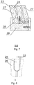
- FIG. 7 is a cross section of the form
- FIG. 8 is a view of the partition arrangement unit.
- a method of manufacturing sections of the carrier cascade vanes 1 of the aircraft reverse reverser from polymer composite materials wherein wounding, in the longitudinal 2 and transverse 3 grooves of the die-bar 4, intersecting longitudinal and the transverse layers of ribs 6 and blades 7 of a cascade vanes section 1 as a continuous harness 5 from unidirectional, for example, carbon filaments impregnated with a polymeric binder, under a certain tension previously set on the creel, by hooking the harness 5 to the pins 8 set at a determined angle to the base of the die-bar and an axis of the ribs and blades when changing the winding direction.
- the grooves 2, 3 have different section, from a rectangular one for the carrier end blades to c-shaped and curved ones, with varying degrees of curvature, drop-shaped for aerodynamic blades and ribs, having the depth 9 commensurate with distance 10 between the grooves 2, 3, with the undercut 11 also proportionate to this distance 10, performing, in the separation layer 12 of the adhesive elastic material to form the rows of the pins 13 located between the grooves 2 for the ribs 6, divided in these rows by the grooves 3 for the blades 7 and reinforced with metal tow hooks 14, which are inserted in a row-by-row manner in the base 15 of the die-bar 4, by orienting them, for example, in the rectangular grooves 16 of the base 15 with the legs 17, for example, of a rectangular cross-section, by securing each leg 17 of the tow hook 14 at the base 15 with a screw 18.
- each row of the pins 13 is pre-made in the form 23 for pouring the anti-adhesive elastic material 12, which is configured as a multi-section box with inner surfaces 24 of the side walls, according to the shape of the surface of a corresponding edge 6, separated by partitions 25 with a cross section identical to the section of a corresponding blade 7.
- the form 23 being assembled from sections 26 of channel-shaped section with beveled shelves 27 to form a common bottom from channel walls 28, by setting sections 26 alternately in guides 29. Then in the grooves 30 identical to the rectangular grooves 16 of the die-bar 4 made in the bottom of the sections 26, inserting the tow hooks 14 of the die-bar 4, in slots 31 between the sections made according to the configuration of the cross section of a corresponding partition 25 on the ends of the beveled shelves, inserting these partitions 25 mainly parallel to the bottom across the shelves. Choosing technological gaps 32 between the sections 26 and the partitions 25, by compressing the latter in the guides 29 using pressure screws 33.
- the use of the invention will allow to create a high-tech design of the sections of the cascade vanes of the aircraft thrust reverser with increased reliability, which confirms the use of the invention for its intended purpose.
- the feasibility of the invention is confirmed by the positive results of testing samples and structural fragments, the development and manufacture of which is completely based on the description presented.
- the new technical solution meets the criterion of "industrial applicability," i.e., the background of the invention.
Landscapes
- Engineering & Computer Science (AREA)
- Mechanical Engineering (AREA)
- Chemical & Material Sciences (AREA)
- Composite Materials (AREA)
- Combustion & Propulsion (AREA)
- General Engineering & Computer Science (AREA)
- Textile Engineering (AREA)
- Moulding By Coating Moulds (AREA)
Applications Claiming Priority (2)
| Application Number | Priority Date | Filing Date | Title |
|---|---|---|---|
| RU2017108683A RU2663249C1 (ru) | 2017-03-16 | 2017-03-16 | Способ изготовления секций несущей решетки реверсера тяги |
| PCT/RU2018/000186 WO2018169453A2 (ru) | 2017-03-16 | 2018-03-23 | Способ изготовления секций несущей решетки реверсера тяги |
Publications (2)
| Publication Number | Publication Date |
|---|---|
| EP3597409A2 true EP3597409A2 (de) | 2020-01-22 |
| EP3597409A4 EP3597409A4 (de) | 2021-03-24 |
Family
ID=63142773
Family Applications (1)
| Application Number | Title | Priority Date | Filing Date |
|---|---|---|---|
| EP18767806.5A Pending EP3597409A4 (de) | 2017-03-16 | 2018-03-23 | Verfahren zur herstellung von abschnitten eines schubumkehrerstützgitters |
Country Status (3)
| Country | Link |
|---|---|
| EP (1) | EP3597409A4 (de) |
| RU (1) | RU2663249C1 (de) |
| WO (1) | WO2018169453A2 (de) |
Cited By (1)
| Publication number | Priority date | Publication date | Assignee | Title |
|---|---|---|---|---|
| EP3892435A1 (de) * | 2020-04-07 | 2021-10-13 | Rohr, Inc. | Hybriddorn zur verwendung in einem werkzeugbestückungsverfahren und herstellung von schubumkehrbarkaskaden und -strukturen, die anfällig für eingeschlossene werkzeuge sind |
Families Citing this family (3)
| Publication number | Priority date | Publication date | Assignee | Title |
|---|---|---|---|---|
| US10723054B2 (en) * | 2017-12-11 | 2020-07-28 | The Boeing Company | Molding insert assembly, molding apparatus, and molding method |
| FR3105071B1 (fr) | 2019-12-19 | 2022-03-25 | Safran | Procédé de fabrication d’une grille en matériau composite |
| CN114179390B (zh) * | 2021-10-25 | 2023-01-10 | 成都飞机工业(集团)有限责任公司 | 一种复合材料格栅类零件成型方法 |
Family Cites Families (13)
| Publication number | Priority date | Publication date | Assignee | Title |
|---|---|---|---|---|
| FR2486153B1 (fr) | 1980-07-04 | 1985-10-04 | Hurel Dubois Avions | Inverseur de poussee pour moteur a reaction, destine notamment a equiper un aeronef |
| US4596621A (en) * | 1984-01-03 | 1986-06-24 | The Boeing Company | Method of making a composite bond cascade for a thrust reverser unit of an aircraft engine nacelle |
| GB2252279A (en) | 1991-02-01 | 1992-08-05 | Rolls Royce Plc | Thrust reverser |
| FR2680547B1 (fr) | 1991-08-21 | 1993-10-15 | Hispano Suiza | Inverseur de poussee de turboreacteur ayant un bord de deviation a courbure evolutive. |
| IT1257222B (it) | 1992-06-09 | 1996-01-10 | Alenia Aeritalia & Selenia | Dispositivo inversore di spinta per motori aeronautici a getto. |
| FR2770802B1 (fr) | 1997-11-13 | 2000-02-11 | Duqueine | Procede de moulage d'une piece composite, structure composite employee dans ce procede et manivelle obtenue selon ce procede |
| US6464170B2 (en) | 2001-03-07 | 2002-10-15 | Lockheed Martin Corporation | Aircraft and aircraft manufacturing method |
| RU2232282C1 (ru) | 2003-03-26 | 2004-07-10 | Открытое акционерное общество Авиамоторный научно-технический комплекс "Союз" | Воздушно-реактивный двигатель с реверсом тяги |
| FR2869258B1 (fr) | 2004-04-27 | 2006-07-21 | Hurel Hispano Sa | Procede de fabrication d'elements, tels que des ailettes pour cascades d'inverseur de poussee, par moulage d'un materiau composite |
| RU2312790C1 (ru) | 2006-06-14 | 2007-12-20 | Открытое акционерное общество Центральный научно-исследовательский институт специального машиностроения | Способ изготовления элементов планера самолета из полимерных композиционных материалов, оправка для осуществления способа изготовления планера самолета и элементы планера самолета из полимерных материалов |
| RU82247U1 (ru) * | 2008-12-26 | 2009-04-20 | Общество с ограниченной ответственностью "Коммерческое научно-производственное объединение "Уральская армирующая компания" | Технологическая линия для изготовления композитной арматуры |
| RU2439728C1 (ru) * | 2010-07-02 | 2012-01-10 | Дмитрий Григорьевич Сильченков | Способ изготовления композиционного сердечника высокотемпературных алюминиевых проводов воздушных линий электропередачи |
| RU2509649C1 (ru) * | 2012-11-01 | 2014-03-20 | Открытое акционерное общество Центральный научно-исследовательский институт специального машиностроения | Способ изготовления секций несущей решетки реверсера тяги самолета из полимерных композиционных материалов, оправка для осуществления способа изготовления секций несущей решетки реверсера тяги самолета из полимерных композиционных материалов, форма для заливки антиадгезионного эластичного материала разделительного слоя оправки для осуществления способа изготовления секций несущей решетки реверсера тяги самолета из полимерных композиционных материалов и секция несущей решетки реверсера тяги самолета из полимерных композиционных материалов |
-
2017
- 2017-03-16 RU RU2017108683A patent/RU2663249C1/ru active
-
2018
- 2018-03-23 WO PCT/RU2018/000186 patent/WO2018169453A2/ru not_active Ceased
- 2018-03-23 EP EP18767806.5A patent/EP3597409A4/de active Pending
Cited By (1)
| Publication number | Priority date | Publication date | Assignee | Title |
|---|---|---|---|---|
| EP3892435A1 (de) * | 2020-04-07 | 2021-10-13 | Rohr, Inc. | Hybriddorn zur verwendung in einem werkzeugbestückungsverfahren und herstellung von schubumkehrbarkaskaden und -strukturen, die anfällig für eingeschlossene werkzeuge sind |
Also Published As
| Publication number | Publication date |
|---|---|
| WO2018169453A3 (ru) | 2018-11-22 |
| WO2018169453A2 (ru) | 2018-09-20 |
| EP3597409A4 (de) | 2021-03-24 |
| RU2663249C1 (ru) | 2018-08-03 |
Similar Documents
| Publication | Publication Date | Title |
|---|---|---|
| EP3597409A2 (de) | Verfahren zur herstellung von abschnitten eines schubumkehrerstützgitters | |
| US11015462B2 (en) | Blade body and a blade made of composite material having fiber reinforcement made up both of three-dimensional weaving and also of short fibers, and method of fabrication | |
| JP6989582B2 (ja) | 複合材ターボ機械ブレードを製造するための方法及びそのための圧縮アセンブリ | |
| US10690111B2 (en) | Wind turbine rotor blade | |
| EP3541613A1 (de) | Verstärkungsstruktur für eine windturbinenschaufel | |
| CN110315771B (zh) | 复合材料叶片以及复合材料叶片的制造方法 | |
| CN107548428B (zh) | 包括带有加固件的平台的叶片 | |
| RU2610971C2 (ru) | Ветровая энергетическая установка | |
| RU2509649C1 (ru) | Способ изготовления секций несущей решетки реверсера тяги самолета из полимерных композиционных материалов, оправка для осуществления способа изготовления секций несущей решетки реверсера тяги самолета из полимерных композиционных материалов, форма для заливки антиадгезионного эластичного материала разделительного слоя оправки для осуществления способа изготовления секций несущей решетки реверсера тяги самолета из полимерных композиционных материалов и секция несущей решетки реверсера тяги самолета из полимерных композиционных материалов | |
| JP2006168558A (ja) | 飛行体用翼、飛行体用翼複合材およびその製造方法 | |
| US11426963B2 (en) | Composite blade and method of forming composite blade | |
| WO2008147402A3 (en) | Helicopter blade mandrel | |
| CN105473847A (zh) | 具有结合在一起的多个分段的风轮机叶片 | |
| CN114746256A (zh) | 用于飞行器发动机的复合材料叶片以及用于制造和修复该复合材料叶片的方法 | |
| US20160200085A1 (en) | Method of manufacturing a frangible blade | |
| JPS5820786B2 (ja) | 可撓性且つ可捻性の要素の製造法 | |
| US9199401B2 (en) | Injection mold core for making a part out of composite material, the part having a closed box | |
| DE112018002819T5 (de) | Verbundwerkstoff-Schaufel und Verfahren zur Herstellung einer Verbundwerkstoff-Schaufel | |
| US20200173292A1 (en) | Composite blade and method for manufacturing composite blade | |
| JP2020176545A5 (de) | ||
| EP3012092B1 (de) | Ringförmiger verbundstofffüller und verfahren zu dessen herstellung | |
| CA2944964C (en) | Apparatus and method for forming fiber reinforced composite structures | |
| EP2524794A1 (de) | Schaum- oder Wabenkern, Rotorblatt aus Schaum- oder Wabenkernen und Verfahren zur Herstellung solch eines Rotorblatts | |
| US11384647B2 (en) | Composite blade and method for molding composite blade | |
| EP2814732B1 (de) | Verfahren und formsystem zur netzformung einer cogehärteten, integrierten struktur |
Legal Events
| Date | Code | Title | Description |
|---|---|---|---|
| STAA | Information on the status of an ep patent application or granted ep patent |
Free format text: STATUS: THE INTERNATIONAL PUBLICATION HAS BEEN MADE |
|
| PUAI | Public reference made under article 153(3) epc to a published international application that has entered the european phase |
Free format text: ORIGINAL CODE: 0009012 |
|
| STAA | Information on the status of an ep patent application or granted ep patent |
Free format text: STATUS: REQUEST FOR EXAMINATION WAS MADE |
|
| 17P | Request for examination filed |
Effective date: 20191014 |
|
| AK | Designated contracting states |
Kind code of ref document: A2 Designated state(s): AL AT BE BG CH CY CZ DE DK EE ES FI FR GB GR HR HU IE IS IT LI LT LU LV MC MK MT NL NO PL PT RO RS SE SI SK SM TR |
|
| AX | Request for extension of the european patent |
Extension state: BA ME |
|
| DAV | Request for validation of the european patent (deleted) | ||
| DAX | Request for extension of the european patent (deleted) | ||
| A4 | Supplementary search report drawn up and despatched |
Effective date: 20210222 |
|
| RIC1 | Information provided on ipc code assigned before grant |
Ipc: F02K 1/58 20060101ALI20210216BHEP Ipc: B29C 53/60 20060101ALI20210216BHEP Ipc: B29C 70/16 20060101ALI20210216BHEP Ipc: B64C 1/00 20060101ALI20210216BHEP Ipc: B29C 70/36 20060101ALI20210216BHEP Ipc: B29C 70/08 20060101AFI20210216BHEP |