EP3597148B1 - Implantat zur retraktion oder/und unterstützung von periurethralem gewebe - Google Patents
Implantat zur retraktion oder/und unterstützung von periurethralem gewebe Download PDFInfo
- Publication number
- EP3597148B1 EP3597148B1 EP19190612.2A EP19190612A EP3597148B1 EP 3597148 B1 EP3597148 B1 EP 3597148B1 EP 19190612 A EP19190612 A EP 19190612A EP 3597148 B1 EP3597148 B1 EP 3597148B1
- Authority
- EP
- European Patent Office
- Prior art keywords
- implant
- prostatic
- elongated edge
- interlobar
- exemplary
- Prior art date
- Legal status (The legal status is an assumption and is not a legal conclusion. Google has not performed a legal analysis and makes no representation as to the accuracy of the status listed.)
- Active
Links
Images


Classifications
-
- A—HUMAN NECESSITIES
- A61—MEDICAL OR VETERINARY SCIENCE; HYGIENE
- A61F—FILTERS IMPLANTABLE INTO BLOOD VESSELS; PROSTHESES; DEVICES PROVIDING PATENCY TO, OR PREVENTING COLLAPSING OF, TUBULAR STRUCTURES OF THE BODY, e.g. STENTS; ORTHOPAEDIC, NURSING OR CONTRACEPTIVE DEVICES; FOMENTATION; TREATMENT OR PROTECTION OF EYES OR EARS; BANDAGES, DRESSINGS OR ABSORBENT PADS; FIRST-AID KITS
- A61F2/00—Filters implantable into blood vessels; Prostheses, i.e. artificial substitutes or replacements for parts of the body; Appliances for connecting them with the body; Devices providing patency to, or preventing collapsing of, tubular structures of the body, e.g. stents
- A61F2/82—Devices providing patency to, or preventing collapsing of, tubular structures of the body, e.g. stents
-
- A—HUMAN NECESSITIES
- A61—MEDICAL OR VETERINARY SCIENCE; HYGIENE
- A61F—FILTERS IMPLANTABLE INTO BLOOD VESSELS; PROSTHESES; DEVICES PROVIDING PATENCY TO, OR PREVENTING COLLAPSING OF, TUBULAR STRUCTURES OF THE BODY, e.g. STENTS; ORTHOPAEDIC, NURSING OR CONTRACEPTIVE DEVICES; FOMENTATION; TREATMENT OR PROTECTION OF EYES OR EARS; BANDAGES, DRESSINGS OR ABSORBENT PADS; FIRST-AID KITS
- A61F2/00—Filters implantable into blood vessels; Prostheses, i.e. artificial substitutes or replacements for parts of the body; Appliances for connecting them with the body; Devices providing patency to, or preventing collapsing of, tubular structures of the body, e.g. stents
- A61F2/02—Prostheses implantable into the body
- A61F2/04—Hollow or tubular parts of organs, e.g. bladders, tracheae, bronchi or bile ducts
-
- A—HUMAN NECESSITIES
- A61—MEDICAL OR VETERINARY SCIENCE; HYGIENE
- A61M—DEVICES FOR INTRODUCING MEDIA INTO, OR ONTO, THE BODY; DEVICES FOR TRANSDUCING BODY MEDIA OR FOR TAKING MEDIA FROM THE BODY; DEVICES FOR PRODUCING OR ENDING SLEEP OR STUPOR
- A61M29/00—Dilators with or without means for introducing media, e.g. remedies
-
- A—HUMAN NECESSITIES
- A61—MEDICAL OR VETERINARY SCIENCE; HYGIENE
- A61B—DIAGNOSIS; SURGERY; IDENTIFICATION
- A61B17/00—Surgical instruments, devices or methods
- A61B17/00234—Surgical instruments, devices or methods for minimally invasive surgery
- A61B2017/00238—Type of minimally invasive operation
- A61B2017/00274—Prostate operation, e.g. prostatectomy, turp, bhp treatment
-
- A—HUMAN NECESSITIES
- A61—MEDICAL OR VETERINARY SCIENCE; HYGIENE
- A61F—FILTERS IMPLANTABLE INTO BLOOD VESSELS; PROSTHESES; DEVICES PROVIDING PATENCY TO, OR PREVENTING COLLAPSING OF, TUBULAR STRUCTURES OF THE BODY, e.g. STENTS; ORTHOPAEDIC, NURSING OR CONTRACEPTIVE DEVICES; FOMENTATION; TREATMENT OR PROTECTION OF EYES OR EARS; BANDAGES, DRESSINGS OR ABSORBENT PADS; FIRST-AID KITS
- A61F2/00—Filters implantable into blood vessels; Prostheses, i.e. artificial substitutes or replacements for parts of the body; Appliances for connecting them with the body; Devices providing patency to, or preventing collapsing of, tubular structures of the body, e.g. stents
- A61F2/02—Prostheses implantable into the body
- A61F2/04—Hollow or tubular parts of organs, e.g. bladders, tracheae, bronchi or bile ducts
- A61F2002/047—Urethrae
Definitions
- the present invention relates to the field of urological medical devices and applications thereof, and more particularly to a urological (prostatic) implant for retracting or/and supporting periurethral tissue enclosing a prostatic urethra along a length of prostate lobes.
- Benign prostate hyperplasia also known as benign prostatic hypertrophy, is a urological disease in which the prostate enlarges and constricts the urethra. BPH affects a majority of the male population over 50 years of age, and is thus of great medical and commercial importance.
- Surgical treatment of hypertrophy of the prostate has been a routine procedure for many years.
- One method of such surgical treatment is open prostatectomy wherein the gland is totally or partially removed.
- Another method of surgical treatment is transurethral resection of the prostate (TURP).
- Surgical treatment is an invasive procedure that may be debilitating, painful and traumatic to the patient. Such surgical treatment may result in various complications including impotence, incontinence, bleeding, infection, and other undesirable problems.
- Another procedure to treat prostatic hypertrophy is to place a catheter at the external opening of the urethra and into the obstructed portions of the urethra, allowing urine to pass from the bladder by way of the catheter lumen.
- These urinary catheters typically employ a positioning or retention balloon at the distal tip which inflates at the bladder neck and prevents the expulsion of the catheter from the body.
- Ablation techniques based on using heat such as produced by microwave or laser energy, may be provided in combination with such catheters for treating the enlarged portion of the prostate.
- heat such as produced by microwave or laser energy
- such a procedure may result in pain and discomfort to the patient.
- BPH benign prostate hyperplasia
- WO2010/073244 appears to disclose that, "An implant for creating incisions in the tissues surrounding the bladder neck and the urethra of a patient, for relaxing the opening of the bladder, the implant includes a central connector and at least one wire, the wires extend radially outwardly from the center of the central connector, the wires apply continuous pressure on the surrounding tissues, the wires are foldable within an implant sheath for enabling delivery and extraction thereof, the implant is implanted within a restricted location of the urethra for a period of time for creating incisions at the locations where the wires apply pressure on the surrounding tissues.”
- WO2008/136005 appears to disclose a, "Device for removing prostate tissue from within the urethra, the device including a plurality of arms, and an actuating mechanism coupled to the arms, the arms being rotatable about a longitudinal axis of the urethra, the arms being divided into arm pairs, each of the arm pair being apart from each other in a first configuration and attempting to get closer to each other, in a second configuration, wherein the device is inserted in the urethra toward the prostate, in the first configuration, and wherein after the device is placed adjacent to the prostate, within the urethra, the actuating mechanism moves the arms to the second configuration, thereby pinching the prostate through the urethra.”
- the invention is defined by appended claim 1. Optional features are presented in the dependent claims.
- the present invention relates to a urological (prostatic) implant for retracting or/and supporting periurethral tissue enclosing a prostatic urethra along a length of prostate lobes.
- Implementation of some embodiments of the disclosure can involve performing or completing selected tasks manually, automatically, or a combination thereof. Moreover, according to actual instrumentation and equipment of some embodiments of the invention, several selected tasks could be implemented by hardware, by software, by firmware, or a combination thereof, using a computerized operating system.
- the present invention relates to the field of urological medical devices and applications thereof, and more particularly to a urological (prostatic) implant for retracting or/and supporting periurethral tissue enclosing a prostatic urethra along a length of prostate lobes.
- situations may arise where such complications and problems are not be directly associated with performing a given BPH treatment technique itself, however, they may be an indirect result or unintended consequence (e.g., side effect) during or/and after performing a given BPH treatment technique.
- Some embodiments of the presently disclosed invention are suitable for treating subjects having conditions of benign prostate hyperplasia (hypertrophy) (BPH), where such treatment is expected to be absent of various possible complications and problems of, or associated with, known BPH treatment techniques. Accordingly, implementation and practice of some embodiments of the present invention may provide at least some solutions to at least some problems associated with known teachings in the field of urological medical devices and applications thereof that are currently used for treating subjects having BPH.
- BPH benign prostate hyperplasia
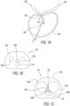
- FIG. 1A schematically illustrates a cross sectional side view of a typical human anatomical region 100 encompassing the lower part of the urinary bladder 102, the prostate 104, and the prostatic urethra 106, where the anatomical region is absent of benign prostate hyperplasia (BPH).
- BPH benign prostate hyperplasia
- FIG. 1B schematically illustrates a cross sectional top view of a portion 110 of the anatomical region 100 shown in FIG.
- FIG. 1A (indicated by the dashed line double arrow 1B-1B therein), highlighting exemplary relative positions, configurations, and sizes of a prostatic urethra 106 in a normal open condition and selected prostatic lobes [dashed line circles], namely, left and right prostatic lateral lobes 114a and 114b, respectively, and prostatic medial lobe 116, during 'normal' conditions absent of BPH.
- 'distal' refers to the direction away from a medical practitioner performing a method or using a device, and closer to a subject's body or towards the midline of the subject's body.
- 'proximal' refers to the direction towards the medical practitioner performing a method or using a device, and farther from a subject's body or away from the midline of the subject's body.
- 'cranial' refers to the direction generally towards a subject's head or brain, or, for example, in a direction towards a urinary bladder and away from a prostate of same subject.
- 'caudal' refers to the direction opposite that of a subject's head or brain, or/and situated in or directed toward the part of the subject's body from which the tail arises.
- 'anterior' refers to the direction towards the front plane of a subject's body.
- posterior' refers to the direction towards the rear plane of a subject's body.
- 'lateral' refers to the direction away from the median and sagittal plane of a subject's body.
- 'medial' (direction), as used herein, refers to the direction towards the median and sagittal plane of a subject's body.
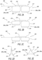
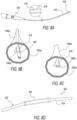
- FIG. 2A schematically illustrates a side view of an exemplary embodiment of an implant (indicated as, and referred to by, reference number 200) for retracting or/and supporting periurethral tissue enclosing a prostatic urethra along a length of prostate lobes, highlighting some prostatic implant components.
- the prostatic implant 200 additionally includes an elongated spine member 210.
- the distal retractor 202 is connected to, or integrally formed as a single structure with, the proximal retractor 206, via the elongated spine member 210 extending along a spinal longitudinal axis 212 or/and a plurality of elongated edge members 214 and 216.
- the distal retractor 202 and the proximal retractor 206 are independently actuatable. Specifically, actuation (i.e., movement or/and change in configuration, shape or form, or/and position) of the distal retractor 202 is independent of actuation (movement or/and change in configuration, shape or form, or/and position) of the proximal retractor 206, and vice versa.
- actuation i.e., movement or/and change in configuration, shape or form, or/and position
- actuation i.e., movement or/and change in configuration, shape or form, or/and position
- FIG. 2B schematically illustrates the exemplary prostatic implant 200 shown in FIG.
- FIG. 2A highlighting the implant distal retractor 202 exhibiting a non-stressed configuration, and the implant proximal retractor 206 exhibiting a stressed configuration.
- FIG. 2C schematically illustrates the exemplary prostatic implant 200, highlighting both the implant distal retractor 202 and the proximal retractor 206 exhibiting a non-stressed configuration.
- exemplary prostatic implant 200 is capable of undergoing a structural change in a manner whereby, for example, the distal retractor 202 is not actuated and remains in a non-stressed configuration (as shown in both FIGs. 2B and 2C ), whereas the proximal retractor 206 is actuated and changes or shifts from a stressed configuration ( FIG. 2B ) to a non-stressed configuration ( FIG. 2C ).
- Such actuation, in the form of configurational change or shift, of the proximal retractor 206 is independent of non-actuation of the distal retractor 202.
- FIG. 2D schematically illustrates a front view of the prostatic implant 200 shown in FIG. 2A exhibiting a stressed configuration
- FIG. 2E schematically illustrates a front view of the prostatic implant 200 shown in FIG. 2C exhibiting a non-stressed configuration.
- Such structural change of the exemplary prostatic implant 200 in changing from a stressed configuration of FIG. 2D to a non-stressed configuration of FIG.
- prostatic implant 200 for retracting or/and supporting periurethral tissue enclosing a prostatic urethra along a length of prostate lobes, according to some embodiments of the invention, are illustratively described with reference to FIGs. 3A and 3B .
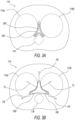
- FIG. 3A schematically illustrates the exemplary embodiment of the stressed prostatic implant 200 shown in FIG. 2D immediately following insertion thereof into the (BPH exhibiting) anatomical region portion 110 shown in FIG. 1C .
- FIG. 3A highlights exemplary (insertion stage) positioning and configuration of the stressed prostatic implant 200 relative to the compressed prostatic urethra 106 and the prostatic lobes (left and right prostatic lateral lobes 114a and 114b, respectively, and prostatic medial lobe 116).
- FIG. 3B schematically illustrates the exemplary prostatic implant 200 shown in FIG. 3A following release thereof inside the (BPH exhibiting) anatomical region portion 110.
- FIG. 3B highlights exemplary (release stage) positioning and configuration of the prostatic implant 200 now being 'less-stressed' (e.g., by undergoing elastic deformation under smaller external stresses, resulting in less strain thereof) relative to the compressed prostatic urethra 106 and the prostatic lobes. Structural change of the prostatic implant 200 (in changing from a stressed configuration of FIG. 3A to a non-stressed configuration of FIG.
- FIG. 3B is accompanied by radially directed forces FR outwardly originating from the distal and proximal retractors 202 and 206, respectively, in a manner such that the prostatic implant 200 laterally expands and changes from a stressed configuration ( FIG. 3A ) to a partially- or less-stressed configuration ( FIG. 3B ).
- This at least, effects anchoring of implant 200 within the particular anatomy of the BPH prostatic urethra, which prevents dislodgement or migration thereof in cranial or caudal directions, as well as rotational movement.
- the distal retractor 202 or/and the proximal retractor 206 are in a form of a pair of first and second curved wing-like structures connected to spine member 210 via interconnecting members 217, and symmetrically opposing each other relative to the spinal longitudinal axis 212.
- each interconnecting member includes at least one elastic portion, for example, elastic portion 218, adjoining the spine member 210, such that the elastic portion is non-stressed when the first curved wing-like structure in the pair is pivotally positioned centrally away from the second curved wing-like structure in the pair about the spinal longitudinal axis 212, so as to form a predetermined maximal elongated edge member spanning angle.
- the prostatic implant 200 additionally includes at least one tissue support member extending between a first elongated edge member, for example, first elongated edge member 214, and the spinal longitudinal axis 212, and at least one other tissue support member extending between a second elongated edge member, for example, second elongated edge member 216, and the spinal longitudinal axis 212.
- the spine member 210 has a length being equal to or less than length of the anterior interlobar groove 118 or/and substantially less than the length of each of the first and second elongated edge members 214 and 216, respectively.
- the first elongated edge member 214 is sized for positioning in the left posterolateral interlobar groove 120a that extends between the left prostatic lateral lobe 114a and the prostatic medial lobe 116
- the second elongated edge member 216 is sized for positioning in the right posterolateral interlobar groove 120b that extends between the right prostatic lateral lobe 114b and the prostatic medial lobe 116.
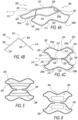
- FIGs. 4A - 4C schematically illustrate a perspective view, a frontal view, and a top view, respectively, of another exemplary embodiment of an implant (indicated as, and referred to by, reference number 300) for retracting or/and supporting periurethral tissue enclosing a prostatic urethra along a length of prostate lobes, highlighting some prostatic implant components.
- exemplary prostatic implant 300 in a non-limiting manner, includes: a distal retractor 302 incorporating a first craniolateral corner 304a and a second craniolateral corner 304b, and a proximal retractor 306 incorporating a first caudolateral corner 308a and a second caudolateral corner 308b.
- the distal retractor 302 and the proximal retractor 306 are independently actuatable.
- actuation i.e., movement or/and change in configuration, shape or form, or/and position
- actuation i.e., movement or/and change in configuration, shape or form, or/and position
- actuation may be in the form of an 'indirect' actuation, for example, by indirectly actuating the distal retractor 302 or/and the proximal retractor 306 using external means.
- the indirect external means may include or involve using an implant delivery system, for example, in a form of an operative combination of an implant manipulator and a compression sleeve, for example, implant manipulator 410 and compression sleeve 404 illustratively described hereinbelow and shown in FIGs. 7A - 7C , and 8A - 8L , in the context of an exemplary embodiment of a prostatic implant system).
- an implant delivery system for example, in a form of an operative combination of an implant manipulator and a compression sleeve, for example, implant manipulator 410 and compression sleeve 404 illustratively described hereinbelow and shown in FIGs. 7A - 7C , and 8A - 8L , in the context of an exemplary embodiment of a prostatic implant system).
- independent actuation of the distal retractor 302 and the proximal retractor 306 of prostatic implant 300 is analogous to that exemplified for the distal retractor 202 and the proximal retractor 206 of prostatic implant 200 shown in FIGs. 2B and 2C .
- the implant distal retractor 302 may exhibit a non-stressed configuration, while the implant proximal retractor 306 may exhibit a stressed configuration.
- both the implant distal retractor 302 and the proximal retractor 306 may exhibit a non-stressed configuration.
- Preceding illustratively described structural change of the exemplary prostatic implant 300 shown in FIGs. 4A - 4C is analogous to that illustratively described hereinabove regarding structural change of the exemplary prostatic implant 200 as shown in FIGs. 2D - 2E . Accordingly, such structural change of the exemplary prostatic implant 300 in changing from a stressed (e.g., compressed) configuration (analogous to that shown in FIG. 2D ) to a non-stressed (e.g., non-compressed) configuration (analogous to that shown in FIG.
- Exemplary implementation and use of the prostatic implant 300, for retracting or/and supporting periurethral tissue enclosing a prostatic urethra along a length of prostate lobes, according to some embodiments of the invention, are analogous to that illustratively described hereinabove regarding the exemplary prostatic implant 200 as shown in FIGs. 3A and 3B .
- Structural change of the prostatic implant 300 in changing from the stressed (compressed or folded) configuration to the non-stressed (partially or entirely unfolded) configuration is accompanied by radially directed forces outwardly originating from the distal and proximal retractors 302 and 306, respectively, in a manner such that the prostatic implant 300 laterally expands (i.e., unfolds) and changes from a stressed (compressed or folded) configuration to a non-stressed (partially or entirely unfolded) configuration.
- exemplary prostatic implant 300 in a non-limiting manner, includes: an elongated spine member 310 having a spinal longitudinal axis 312, and, a first elongated edge member 314 and a second elongated edge member 316 symmetrically opposing each other relative to the spinal longitudinal axis 312.
- each of the first and second elongated edge members 314 and 316, respectively, is interconnected to the spine member 310 via at least one interconnecting member, for example, interconnecting member 320.
- anterior interlobar groove for example, anterior interlobar groove 118 shown in FIGs. 1C , 3A, 3B
- first and second elongated edge members 314 and 316 respectively engage corresponding posterolateral interlobar grooves (for example, left and right posterolateral interlobar grooves 120a and 120b, shown in FIGs. 1C , 3A, 3B ).
- the prostatic implant 300 is configured to anchor the anterior interlobar groove 118, and, the left and right posterolateral interlobar grooves 120a and 120b, respectively, by continuously exerting a radially directed pushing force thereupon, within a range of between about 100 grams and about 1,000 grams (between 0.98 N and 9.8 N), so as to prevent or minimize axial or/and rotational movement of the anchored anterior interlobar groove 118, and, the posterolateral interlobar grooves 120a and 120b.
- the prostatic implant 300 is configured to anchor the anterior interlobar groove 118, and, the left and right posterolateral interlobar grooves 120a and 120b, respectively, by continuously exerting a radially directed pushing force thereupon, so as to increase distance separating superior portions of the interlobar grooves and increase distance separating left and right inferior portions of the interlobar grooves, or/and to maintain a distance of at least 2 mm between the prostatic lateral lobes, by exerting lateral forces thereupon within a range of between about 100 grams and about 1,000 grams (between 0.98 N and 9.8 N).
- each of the interconnecting members for example, interconnecting member 320, includes at least one elastic portion, for example, elastic portion 328, adjoining the spine member 310, such that the elastic portion 328 is non-stressed when the first and second elongated edge members 314 and 316, respectively, are pivotally positioned centrally away from each other about the spinal longitudinal axis 312, so as to form a predetermined maximal spanning angle between opposing interconnecting members.
- the predetermined maximal spanning angle is within a range of between about 60° and about 140°.
- first and second edge members 314 and 316 are configured to approach each other so as to form an elongated edge member spanning angle being equal to or greater than about 60° degrees.
- each of the first and second elongated edge members 314 and 316, respectively, or/and each of the first and second tissue support members 322 and 324, respectively exerts a total lateral pressing force upon a corresponding prostatic lateral lobe.
- the total lateral pressing force is in a range of between about 100 grams and about 1,000 grams (between 0.98 N and 9.8 N) .
- At least one of the first and second elongated edge members 314 and 316, respectively, has a cranial-nose portion, for example, cranial-nose portion 340, shaped and configured for resting against a ledge imposed by a urinary bladder neck segment adjacent the prostatic urethra (e.g., 108 in FIG. 1A ), so as to prevent cranial dislodgement of the prostatic implant 300 into the urinary bladder (e.g., 102 in FIG. 1A ), when the spine member 310 engages an anterior interlobar groove (e.g., 118 in FIG.
- a cranial-nose portion for example, cranial-nose portion 340, shaped and configured for resting against a ledge imposed by a urinary bladder neck segment adjacent the prostatic urethra (e.g., 108 in FIG. 1A ), so as to prevent cranial dislodgement of the prostatic implant 300 into the urinary bladder (e.g., 102
- the cranial-nose portion 340 is "L" shaped.
- At least one of the first and second elongated edge members 314 and 316 has a caudal-nose portion, for example, caudal-nose portion 342, shaped and configured for resting against a narrowing imposed by the external urethral sphincter adjacent to the verumontanum of the prostatic urethra, so as to prevent caudal migration of the prostatic implant 300 through the external sphincter and into the bulbar urethra, when the spine member 302 engages an anterior interlobar groove (e.g., 118 in FIG.
- an anterior interlobar groove e.g., 118 in FIG.
- the caudal-nose portion 342 is "L" shaped.
- FIG. 6 schematically illustrates the exemplary prostatic implant shown in FIG. 4C , highlighting inclusion therein of a pair of exemplary first and second tissue support members 360 and 362, with each such tissue support member including a tissue contacting surface, for example, first and second tissue contacting surfaces 364 and 366, respectively.
- At least one of the tissue support members includes a tissue contacting surface, such as tissue contacting surface 364 or 366, sized or/and shaped according to dimensions of a portion of a prostatic lateral lobe (for example, left or right prostatic lateral lobe 114a or 114b, respectively, shown in FIGs. 1C , 3A, 3B ).
- tissue contacting surface such as tissue contacting surface 364 or 366, sized or/and shaped according to dimensions of a portion of a prostatic lateral lobe (for example, left or right prostatic lateral lobe 114a or 114b, respectively, shown in FIGs. 1C , 3A, 3B ).
- an aspect of some embodiments of the present invention is a system (herein, also referred to as a prostatic implant system) for retracting or/and supporting periurethral tissue enclosing a prostatic urethra along a length of prostate lobes.
- the prostatic implant system in a non-limiting manner, includes: an implant (prostatic implant), and an implant (prostatic implant) manipulator detachably connected to the implant (prostatic implant).
- any of the hereinabove illustratively described exemplary embodiments of an implant such as exemplary prostatic implant 200 or exemplary prostatic implant 300, for retracting or/and supporting periurettiral tissue enclosing a prostatic urethra along a length of prostate lobes may be included as part of, and used for implementing, the herein disclosed exemplary embodiments of a system (prostatic implant system) for retracting or/and supporting periurethral tissue enclosing a prostatic urethra along a length of prostate lobes.
- exemplary prostatic implant system 400 in a non-limiting manner, includes: an implant (prostatic implant) 300, and an implant (prostatic implant) manipulator 410 detachably connected to the prostatic implant 300.
- the prostatic implant 300 includes a plurality of elongated edge members, for example, first and second elongated edge members 314 and 316, respectively, interconnected in a form of a collapsible-expandable frame expandable to retract or/and support periurethral tissue by exerting pushing forces upon interlobar grooves located along the prostatic urethra (e.g., as illustratively described hereinabove with reference to FIGs.
- FIGs. 7B - 7C schematically illustrate exemplary embodiments of the prostatic implant system 400, highlighting progressive (sequential) stages of operation thereof, wherein the exemplary prostatic implant 300 is deployed via progressively (sequentially) being pushed out of the compression sleeve 404 by the implant manipulator 410, along with undergoing a type of unfolding of at least some of its structural members.
- distal retractor 302 emerges and then immediately unfolds, at least partly, while the other part of implant 300 is held folded and compressed in compression sleeve 404; followed by ( FIG. 7C ) complete extraction of implant 300 from within compression sleeve 404, where implant 300 is unfolded at least partly along most or all its entire length.
- the implant manipulator 410 (e.g., FIGs. 8E - 8G ) is configured for progressively (sequentially) changing the shape or form of the prostatic implant 300 according to different progressive or sequential implant deployment configurations, including at least one of the following.
- the implant manipulator 410 when connected to the prostatic implant 300, is configured for applying thereto at least one of rotational forces, pulling forces, and pushing forces.
- the implant manipulator 410 applies such forces to the prostatic implant 300 so as to facilitate and effect preceding illustratively described progressive (sequential) changing of the shape or form of the prostatic implant 300, according to the different progressive or sequential prostatic implant deployment configurations.
- the implant manipulator 410 includes a tubular member, for example, tubular member 412, and a tether, for example, tether 414, releasably intertwined through both of the implant first and second caudolateral corners.
- the implant manipulator 410 is configured for continuously or/and selectively pulling the prostatic implant 300 via an operator using the tether 414 against a distal end 416 of the tubular member 412.
- the prostatic implant system 400 additionally includes an over-sheath, for example, over-sheath 418 shown in FIGs. 8A - 8C , sized for covering a length of the cystoscope 402 having a cystoscope lumen (e.g., as a type of 'working channel') dimensioned to restrain the prostatic implant 300 in the fully collapsed delivery configuration (e.g., FIG. 7A ) via at least encircling the implant first and second craniolateral corners.
- an over-sheath for example, over-sheath 418 shown in FIGs. 8A - 8C , sized for covering a length of the cystoscope 402 having a cystoscope lumen (e.g., as a type of 'working channel') dimensioned to restrain the prostatic implant 300 in the fully collapsed delivery configuration (e.g., FIG. 7A ) via at least encircling the implant first and second craniolateral corners.
- FIGs. 7B Such manipulating and shifting is effected by the implant manipulator 410 detaching from the prostatic implant 300 after release of the tether 414 from the implant first and second caudolateral corners 308a and 308b, respectively.
- any of the hereinabove illustratively described exemplary embodiments of an implant (prostatic implant) for retracting or/and supporting periurethral tissue enclosing a prostatic urethra along a length of prostate lobes may be included as part of, and used for implementing, the herein disclosed exemplary embodiments of a system (prostatic implant system) for retracting or/and supporting periurethral tissue enclosing a prostatic urethra along a length of prostate lobes.
- the prostatic implant 300 includes: an elongated spine member 310 having a spinal longitudinal axis 312, and, first and second elongated edge members 314 and 316, respectively, symmetrically opposing each other relative to the spinal longitudinal axis 312, and interconnected to the spine member 310 via at least one interconnecting member 320.
- the spine member 310 has a length being equal to or less than length of an anterior interlobar groove (e.g., 118 in FIGs.
- prostatic lateral lobes e.g., left and right prostatic lateral lobes 114a and 114b, respectively, in FIGs. 1C , 3A, 3B
- the first elongated edge member 314 is sized for positioning in a left posterolateral interlobar groove 120a that extends between a left prostatic lateral lobe 114a and a prostatic medial lobe 116
- the second elongated edge member 316 is sized for positioning in a right posterolateral interlobar groove 120b that extends between a right prostatic lateral lobe 114b and the prostatic medial lobe 116.
- At least one of the implant first and second craniolateral corners 304a and 304b, respectively, are shaped and configured for resting against a ledge imposed by the urinary bladder neck (e.g., 108) so as to prevent cranial dislodgement of the prostatic implant 300 into the urinary bladder (e.g., 102), when the spine member 310 engages an anterior interlobar groove (e.g., 118) that extends between prostatic lateral lobes (e.g., 114a and 114b), and when the first and second elongated edge members 314 and 316, respectively, engage corresponding posterolateral interlobar grooves (e.g., 120a and 120b).
- an anterior interlobar groove e.g., 118
- prostatic lateral lobes e.g., 114a and 114b
- first and second elongated edge members 314 and 316 respectively engage corresponding posterolateral interlobar grooves (e.g., 120a and
- each of the implant first and second caudolateral corners 308a and 308b, respectively has a shape or form of a proximally directed apex, wherein the apex is formed by intersection of converging curved slopes of respective ones of the implant first and second caudolateral corners 308a and 308b, respectively.
- the prostatic implant method in a non-limiting manner, includes:
- the prostatic implant method in a non-limiting manner, includes:
- FIGs. 8A - 8N schematically illustrate various stages of delivering and deploying an exemplary prostatic implant, such as prostatic implant 300 illustratively described hereinabove and shown in FIGs. 4A, 4C , and 7D , for retracting or/and supporting periurethral tissue enclosing a prostatic urethra along a length of prostate lobes, using an exemplary system, such as prostatic implant system, such as prostatic implant system 400 illustratively described hereinabove and shown in FIGs. 7A - 7C ).
- prostatic implant system such as prostatic implant system 400 illustratively described hereinabove and shown in FIGs. 7A - 7C .
- over-sheath 418 is sleeved over the longitudinal body 419 of a urological endoscope, particularly, a cystoscope (also known as a lithoscope), for example, cystoscope 402.
- a cystoscope also known as a lithoscope
- cystoscope 402. some preliminary steps may be taken by an operator, such as a medical practitioner, in order to scan the treatment area or/and to measure patient-specific anatomical dimensions, optionally, in order to select an implant of proper size for a chosen result.
- over-sheath 418, together with cystoscope 402 is then extended throughout the length of the prostatic urethra 106sa, where the cystoscope distal end 420 is provided adjacent to or inside of the urinary bladder 102sa.
- the prostatic urethra 106sa, the urinary bladder 102sa, and the bladder neck 108sa are drawn for illustrative purposes only, and, in a non-limiting manner, may be considered 'simulated analogs' of the corresponding bodily organs or parts, namely, prostatic urethra 106, urinary bladder 102, and bladder neck 108, schematically shown in FIGs. 1A - 1C .
- Cystoscope 402 is removed from the prostatic urethra 106sa while, optionally, keeping over-sheath 418 in place (as shown in FIG. 8C ).
- compression sleeve 404 is then loaded over cystoscope outer periphery 420 (as shown in FIG. 8D ), in preparation of loading prostatic implant 300 into the cystocope 402 and collapsing of the prostatic implant 300 using the compression sleeve 404.
- First and second craniolateral corners are then urged the into close proximity to each other, so as to effect changing of the prostatic implant 300 into the partially collapsed (partially folded / partially unfolded) positioning configuration, by pulling tether 414 against the distal end 416 of the tubular member 412.
- the implant manipulator 410 which can assist in exemplary subsequent steps, such as of implant delivery, positioning or/and activating, can be formed by threading tether 414 through the lumen of the tubular member 412, and optionally fixating proximal end (e.g., proximal both free ends 414a and 414b) of tether 414 relative to the proximal end 424 of tubular member 412.
- FIG. 8E demonstrates an exemplary formation of the implant manipulator 410 connected with the prostatic implant 300, also forcing it into the partially collapsed (partially folded / partially unfolded) positioning configuration.
- FIG. 8F shows the implant manipulator 410, with the prostatic implant 300 connected thereto, are then loaded into a lumen (e.g., working channel 422) of the cystoscope 402.
- a lumen e.g., working channel 422
- the proximal end of the implant manipulator 410 is passed into the distal opening of the working channel 422 ( FIG. 8F (i)), while the proximal end of the implant manipulator 410 is drawn from a proximal opening 430 of the working channel 422 ( FIG. 8F (ii)).
- FIG. 8G shows the prostatic implant 300 in its partially collapsed (partially folded / partially unfolded) positioning configuration coupled to the cystoscope 402 using the implant manipulator 410 (not shown, fully inserted within working channel 422).
- the prostatic implant 300 is then forced into a fully collapsed (fully folded) delivery configuration using the compression sleeve 402, by drawing the compression sleeve 404 over entire length of the prostatic implant 300.
- the compression sleeve 404 incorporates a lumen 432 sized for effecting changing of the configuration of the prostatic implant 300 from the partially collapsed (partially folded / partially unfolded) positioning configuration to the fully collapsed (fully folded) delivery configuration.
- the prostatic implant 300 is then pushed distally through over-sheath 418 with the cystoscope 402 ( FIG. 8I ) and passed, still in its fully collapsed (fully folded) delivery configuration, in a cranial direction in the prostatic urethra 106sa, into the urinary bladder 102sa of the subject. Then, the prostatic implant distal retractor 302 is released from its restricting boundary, namely, the working channel 422 and the over-sheath 418, until at least the distal retractor 302, and, optionally, also the proximal retractor 306, protrudes in a cranial direction from the prostatic urethra 106sa (as shown, for example, in FIG. 8J ).
- This may be effected by either pushing the prostatic implant 300, optionally relative to the over-sheath 418, or/and the cystoscope 402 further into the urinary bladder 102sa, or by holding the prostatic implant 300 in the urinary bladder 102sa, using the implant manipulator 410, while proximally pulling over-sheath 418 or/and the cystoscope 402.
- Releasing the prostatic implant 300 should effect expansion of the distal retractor 302 within inner boundaries of the urinary bladder 102sa into the partially collapsed (partially folded / partially unfolded) positioning configuration, resulting in the first and second craniolateral corners 304a and 304b, respectively, being distanced apart from each other, and, the first and second caudolateral corners 308a and 308b, respectively, being kept in close proximity to each other.
- the prostatic implant 300 is positioned in the prostatic urethra 106sa along the length of the prostate lobes, as shown in part, in FIG. 8K .
- the prostatic implant 300 positioning in the prostatic urethra 106sa may include at least one of the following steps, not necessarily in same order:
- the prostatic implant 300 positioning should result, if the prostatic implant 300 is in its partially collapsed (partially folded / partially unfolded) positioning configuration, in effecting expansion of a distal region of the prostatic urethra 106sa, using the distal retractor 302, into a greater lumen size than an adjacent proximal region of the prosthetic urethra 106sa.
- the distal retractor 302 may also be partially collapsed into conformity with anatomy of the distal region of the prostatic urethra 106sa.
- FIG. 8L provides a frontal (caudally directed) view for an exemplary representation of proper positioning of the prostatic implant 300 within the prostatic urethra 106sa.
- the configuration of the prostatic implant 300 can be changed from the fully collapsed (fully folded) delivery configuration into an expanded (fully unfolded) deployed configuration.
- expansion (unfolding) of the prostatic implant 300 is effected in a partial manner, whereby at least most, but not necessarily all, of the prostatic implant 300 structural members change into a fully expanded (unfolded) configuration, for example, possibly due to physical size and dimensional restrictions imposed by the in-vivo environment of the periurethral tissue and the surrounding prostatic lobes.
- the expansion (unfolding) procedure results in the first and second craniolateral corners 304a and 304b, respectively, to become distanced apart from each other, and, the first and second caudolateral corners 308a and 308b, respectively, to become distanced apart from each other as well.
- the first and second tissue support members 322 and 324, respectively, of the prostatic implant 300 are also released for supporting respective portions of the lateral prostatic lobes following implant positioning.
- the cystoscope 402 is then removed from the prostatic urethra 106sa, and from the entire urethra of the subject, while keeping the over-sheath 418 in place.
- any of the hereinabove illustratively described steps or procedures of the herein disclosed exemplary embodiments of a method (prostatic implant method) for retracting or/and supporting periurethral tissue enclosing a prostatic urethra along a length of prostate lobes, may be repeated in case there is a need to change (e.g., correct) positioning of the prostatic implant 300, or of any portion or member thereof, in relation to chosen anatomical or/and physiological considerations. Repeating any of the previous steps may include, be preceded by, or be followed by, re-collapsing the prostatic implant 300 back into the fully collapsed delivery configuration or/and passing the prostatic implant 300 back into the urinary bladder 102sa.
- the chosen result can be verified under vision, for example, using the cystoscope 402.
- the chosen result may include anchoring different portions of the prostatic implant 300 in at least two of the anterior interlobar grooves, the left posterolateral interlobar groove, and the right posterolateral interlobar groove, of the prostatic urethra 106sa, within the boundaries of the prostate lobes.
- the chosen result may also include lifting both prostatic lateral lobes so as to enlarge minimal lumen size of the prostatic urethra 106sa, optionally, to at least 1 mm, or at least 2 mm, along a continuous length of the prostatic urethra, optionally along its entire length, optionally, by shifting each of the prostatic lateral lobes, pivotally, relative to the anterior interlobar groove.
- the fully deployed and implanted prostatic implant 300 is thereby configured and positioned to continuously exert radially directed pushing forces upon the anterior interlobar groove and at least one of the left and right posterolateral interlobar grooves.
- This may facilitate preventing or minimizing possible axial or/and rotational movement of the prostatic implant 300, or/and to increase distance separating the superior interlobar grooves and to increase distance separating the left and right inferior-lateral interlobar grooves.
- Such may also facilitate the prostatic implant 300 to exert lateral pressing forces upon each prostatic lateral lobe, thereby, retracting or/and supporting the periurethral tissue.
- the implant manipulator 410 is taken apart into its main parts, namely, the tubular member 412 and the tether 414 (partly shown in FIG. 8M , illustrating scissoring of the implant manipulator 410), and the tether 414 is pulled and withdrawn from holding the prostatic implant 300 and subsequently, from the subject's body ( FIG. 8N ).
- 'a', 'an', and 'the' means 'at least one', or 'one or more'. Use of the phrase 'one or more' herein does not alter this intended meaning of 'a', 'an', or 'the'. Accordingly, the terms 'a', 'an', and 'the', as used herein, may also refer to, and encompass, a plurality of the stated entity or object, unless otherwise specifically defined or stated herein, or, unless the context clearly dictates otherwise.
- phrases: 'a unit', 'a device', 'an assembly', 'a mechanism', 'a component', 'an element', and 'a step or procedure' may also refer to, and encompass, a plurality of units, a plurality of devices, a plurality of assemblies, a plurality of mechanisms, a plurality of components, a plurality of elements, and, a plurality of steps or procedures, respectively.
- Each of these terms is considered equivalent in meaning to the phrase 'consisting essentially of'.
- phrases 'consisting essentially of, as used herein, means that the stated entity or item (system, system unit, system sub-unit, device, assembly, sub-assembly, mechanism, structure, component, element, or, peripheral equipment, utility, accessory, or material, method or process, step or procedure, sub-step or sub-procedure), which is an entirety or part of an exemplary embodiment of the disclosed invention, or/and which is used for implementing an exemplary embodiment of the disclosed invention, may include at least one additional 'feature or characteristic' being a system unit, system sub-unit, device, assembly, sub-assembly, mechanism, structure, component, or element, or, peripheral equipment, utility, accessory, or material, step or procedure, sub-step or sub-procedure), but only if each such additional 'feature or characteristic' does not materially alter the basic novel and inventive characteristics or special technical features, of the claimed entity or item.
- 'method' refers to steps, procedures, manners, means, or/and techniques, for accomplishing a given task including, but not limited to, those steps, procedures, manners, means, or/and techniques, either known to, or readily developed from known steps, procedures, manners, means, or/and techniques, by practitioners in the relevant field(s) of the disclosed invention.
- a stated or described numerical range 'from 1 to 6' also refers to, and encompasses, all possible sub-ranges, such as 'from 1 to 3', 'from 1 to 4', 'from 1 to 5', 'from 2 to 4', 'from 2 to 6', 'from 3 to 6', etc., and individual numerical values, such as '1', '1.3', '2', '2.8', '3', '3.5', '4', '4.6', '5', '5.2', and '6', within the stated or described numerical range of 'from 1 to 6'.
Landscapes
- Health & Medical Sciences (AREA)
- Engineering & Computer Science (AREA)
- Biomedical Technology (AREA)
- Life Sciences & Earth Sciences (AREA)
- Veterinary Medicine (AREA)
- Public Health (AREA)
- General Health & Medical Sciences (AREA)
- Animal Behavior & Ethology (AREA)
- Heart & Thoracic Surgery (AREA)
- Transplantation (AREA)
- Vascular Medicine (AREA)
- Oral & Maxillofacial Surgery (AREA)
- Cardiology (AREA)
- Pulmonology (AREA)
- Gastroenterology & Hepatology (AREA)
- Anesthesiology (AREA)
- Hematology (AREA)
- Prostheses (AREA)
- Surgical Instruments (AREA)
- Materials For Medical Uses (AREA)
Claims (15)
- Implantat (300) zum Zurückziehen oder/und Stützen von Periurethralgewebe, das eine Prostata-Harnröhre entlang einer Länge von Prostatalappen (114a, 114b) umschließt, wobei das Implantat umfasst:ein langgestrecktes Rückgratelement (310) mit einer Rückgratlängsachse (312, 210);ein erstes langgestrecktes Randelement (314) und ein zweites langgestrecktes Randelement (316), die sich in Bezug auf die Rückgratlängsachse (312, 210) symmetrisch gegenüberliegen, wobei jedes langgestreckte Randelement (314, 316) über mindestens ein Verbindungselement (320) mit dem Rückgratelement (310) verbunden ist; undmindestens ein Gewebeträgerelement (322, 354, 356, 362), das sich zwischen dem ersten langgestreckten Randelement (314) und der Rückgratlängsachse (312, 210) erstreckt, und mindestens ein weiteres Gewebeträgerelement (324, 350, 352, 360), das sich zwischen dem zweiten langgestreckten Randelement (316) und der Rückgratlängsachse (312, 210) erstreckt, wobei jedes Gewebeträgerelement (320) bemessen und konfiguriert ist, um einen Teil eines Prostataseitenlappens (114a, 114b) zu stützen, wenn das Rückgratelement (310) in eine vordere Interlobarfurche (118) eingreift, die sich zwischen den Prostataseitenlappen (114a, 114b) erstreckt, und wenn das erste und das zweite langgestreckte Randelement (314, 316) in entsprechende posterolaterale Interlobarfurchen (120a, 120b) eingreifen, wobei das Rückgratelement (310) eine Länge aufweist, die wesentlich geringer ist als die Länge jedes der ersten und zweiten langgestreckten Randelemente (314, 316), wobei das erste langgestreckte Randelement (314) bemessen ist, um in einer linken posterolateralen Interlobarfurche (120a) positioniert zu werden, die sich zwischen einem linken Prostataseitenlappen (114a) und einem Prostatamittellappen (116) erstreckt, und das zweite langgestreckte Randelement (316) bemessen ist, um in einer rechten posterolateralen Interlobarfurche (120b) positioniert zu werden, die sich zwischen einem rechten Prostataseitenlappen (114b) und dem Prostatamittellappen (116) erstreckt.
- Implantat nach Anspruch 1, bei dem das Rückgratelement (310) eine Länge aufweist, die gleich oder kleiner als die Länge der vorderen Interlobarfurche (118) ist.
- Implantat nach Anspruch 1, bei dem jedes der Verbindungselemente (320) mindestens einen elastischen Abschnitt (328) umfasst, der an das Rückgratelement (310) angrenzt, wobei der elastische Abschnitt (328) nicht belastet ist, wenn die ersten und zweiten langgestreckten Randelemente (314, 316) schwenkbar zentral voneinander weg um die Rückgratlängsachse (312, 210) positioniert sind, um einen vorgegebenen maximalen Spannwinkel zwischen gegenüberliegenden Verbindungselementen (320) zu bilden.
- Implantat nach Anspruch 3, bei dem der vorgegebene maximale Spannwinkel in einem Bereich zwischen etwa 60° und etwa 140° liegt.
- Implantat nach Anspruch 3, bei dem der mindestens eine elastische Abschnitt (328) eine Spannungszunahme aufweist, wenn er einem Kraftmoment ausgesetzt ist, das die ersten und zweiten langgestreckten Randelemente (314, 316) um die Rückgratlängsachse (312, 210) herum schwenkend aufeinander zu verschiebt.
- Implantat nach Anspruch 3, bei dem das erste und das zweite Randelement (314, 316) konfiguriert sind, um sich einander so anzunähern, dass zwischen den gegenüberliegenden Verbindungselementen (320) ein Spannwinkel gebildet wird, der gleich oder größer als etwa 60° ist, wenn das erste und das zweite langgestreckte Randelement (314, 316) oder/und jedes Gewebeträgerelement (322) eine gesamte seitliche Druckkraft auf einen entsprechenden Prostatalappen (114a, 114b) ausübt, wobei die gesamte seitliche Druckkraft in einem Bereich zwischen etwa 0,98 N und etwa 9, 8 N (zwischen etwa 100 Gramm und etwa 1000 Gramm) liegt.
- Implantat nach Anspruch 1, bei dem das mindestens eine Gewebeträgerelement (322) als ein gekrümmter Abschnitt des ersten oder/und zweiten langgestreckten Randelements (314, 316) konfiguriert ist, der zu der Rückgratlängsachse (312, 210) hin vorsteht.
- Implantat nach Anspruch 1, bei dem das mindestens eine Gewebeträgerelement (322) als krummliniger Abschnitt des ersten oder/und zweiten langgestreckten Randelements (314, 316) konfiguriert ist, der von einem Bereich, der von dem ersten oder/und zweiten langgestreckten Randelement (314, 316) und dem Wirbelsäulenelement (310) umschlossen ist, seitlich nach außen vorsteht.
- Implantat nach Anspruch 1, bei dem das mindestens eine Gewebeträgerelement (322) als Rippe oder rippenartiges Element konfiguriert ist, das sich von einem der Verbindungselemente (320) aus erstreckt.
- Implantat nach Anspruch 9, bei dem die Rippe oder das rippenartige Element von einem Umfangsbereich aus, der von einem entsprechenden langgestreckten Randelement (314, 316) und dem Rückenelement (310) umschlossen ist, seitlich nach außen gekrümmt oder gebogen ist.
- Implantat nach Anspruch 1, bei dem das mindestens eine Gewebeträgerelement (322) eine Gewebekontaktoberfläche umfasst, die entsprechend den Abmessungen des Abschnitts des Prostataseitenlappens (114a, 114b) bemessen und/oder geformt ist.
- Implantat nach Anspruch 1, das zum Verankern der vorderen Interlobarfurche (118) und der linken und rechten posterolateralen Interlobarfurchen (120a, 120b) durch kontinuierliches Ausüben einer radial gerichteten Druckkraft auf diese in einem Bereich zwischen etwa 0,98 N und etwa 9,8 N (zwischen etwa 100 Gramm und etwa 1000 Gramm) konfiguriert ist, um eine axiale oder/und rotatorische Bewegung der verankerten vorderen Interlobarfurche (118) und der linken und rechten posterolateralen Interlobarfurchen (120a, 120b) zu verhindern oder zu minimieren.
- Implantat nach Anspruch 1, das zum Verankern der vorderen Interlobarfurche(118) und der linken und rechten posterolateralen Interlobarfurchen (120a, 120b) durch kontinuierliches Ausüben einer radial gerichteten Druckkraft auf diese konfiguriert ist, um den Abstand zwischen den oberen Abschnitten der Interlobarfurchen (120, 120b) und den Abstand zwischen den linken und rechten unteren Abschnitten der Interlobarfurchen (120, 120b) zu vergrößern, oder/und um einen Abstand von mindestens 2 mm zwischen den Prostataseitenlappen (114a, 114b) aufrechtzuerhalten, indem darauf laterale Kräfte in einem Bereich zwischen etwa 0,98 N und etwa 9,8 N (zwischen etwa 100 Gramm und etwa 1000 Gramm) ausgeübt werden.
- Implantat nach Anspruch 1, bei dem mindestens eines von erstem und zweitem langgestrecktem Randelement (314, 316) einen Kranial-Nasenabschnitt (340) umfasst, der geformt und konfiguriert ist, um an einer Kante anzuliegen, die durch ein Harnblasenhalssegment (108) angrenzend an die Prostataharnröhre (106) gebildet ist, um so ein Verschieben des Implantats (300) nach kranial in die Harnblase zu verhindern, wenn das Rückgratelement (310) in eine vordere Interlobarfurche (118) eingreift, die sich zwischen den Prostataseitenlappen (114a, 114b) erstreckt, und wenn das erste und das zweite langgestreckte
Randelement (314, 316) in entsprechende posterolaterale Interlobarfurchen (120a, 120b) eingreifen, wobei optional der Kranial-Nasenabschnitt (340) "L"-förmig ist. - Implantat nach Anspruch 1, bei dem mindestens eines von erstem und zweitem langgestrecktem Randelement (314, 316) einen Kaudal-Nasenabschnitt (342) umfasst, der zum Anliegen an einer Verengung geformt und konfiguriert ist, die durch einen äußeren Harnröhrenschließmuskel benachbart zum Verumontanum der Prostataharnröhre gebildet ist, um so eine Migration des Implantats (300) nach Kaudal durch den äußeren Schließmuskel und in die bulbäre Harnröhre zu verhindern, wenn das Rückgratelement (310) in eine vordere Interlobarfurche (118) eingreift, die sich zwischen den Prostataseitenlappen (114a, 114b) erstreckt, und wenn das erste und das zweite langgestreckte
Randelement (314, 316) in entsprechende posterolaterale Interlobarfurchen (120a, 120b) eingreifen, wobei optional der Kaudal-Nasenabschnitt (342) L-förmig ist.
Priority Applications (5)
| Application Number | Priority Date | Filing Date | Title |
|---|---|---|---|
| PL19190612.2T PL3597148T3 (pl) | 2015-07-29 | 2015-07-29 | Implant do odciągania lub/i podtrzymywania tkanki okołocewkowej |
| EP19190612.2A EP3597148B1 (de) | 2015-07-29 | 2015-07-29 | Implantat zur retraktion oder/und unterstützung von periurethralem gewebe |
| ES19190612T ES3033314T3 (en) | 2015-07-29 | 2015-07-29 | Implant for retracting or/and supporting periurethral tissue |
| HUE19190612A HUE071642T2 (hu) | 2015-07-29 | 2015-07-29 | Implantátum periurethrális szövetnek a visszahúzására és/vagy megtámasztására |
| SM20250209T SMT202500209T1 (it) | 2015-07-29 | 2015-07-29 | Impianto per la retrazione e/o il sostegno del tessuto periuretrale |
Applications Claiming Priority (3)
| Application Number | Priority Date | Filing Date | Title |
|---|---|---|---|
| EP15760272.3A EP3328317B1 (de) | 2015-07-29 | 2015-07-29 | Retraktion oder/und unterstützung von periurethralem gewebe |
| EP19190612.2A EP3597148B1 (de) | 2015-07-29 | 2015-07-29 | Implantat zur retraktion oder/und unterstützung von periurethralem gewebe |
| PCT/IB2015/055731 WO2017017499A1 (en) | 2015-07-29 | 2015-07-29 | Retracting or/and supporting periurethral tissue |
Related Parent Applications (2)
| Application Number | Title | Priority Date | Filing Date |
|---|---|---|---|
| EP15760272.3A Division EP3328317B1 (de) | 2015-07-29 | 2015-07-29 | Retraktion oder/und unterstützung von periurethralem gewebe |
| EP15760272.3A Division-Into EP3328317B1 (de) | 2015-07-29 | 2015-07-29 | Retraktion oder/und unterstützung von periurethralem gewebe |
Publications (3)
| Publication Number | Publication Date |
|---|---|
| EP3597148A1 EP3597148A1 (de) | 2020-01-22 |
| EP3597148B1 true EP3597148B1 (de) | 2025-04-16 |
| EP3597148C0 EP3597148C0 (de) | 2025-04-16 |
Family
ID=54065410
Family Applications (3)
| Application Number | Title | Priority Date | Filing Date |
|---|---|---|---|
| EP22194729.4A Pending EP4140444A1 (de) | 2015-07-29 | 2015-07-29 | Retraktion oder/und unterstützung von periurethralem gewebe |
| EP19190612.2A Active EP3597148B1 (de) | 2015-07-29 | 2015-07-29 | Implantat zur retraktion oder/und unterstützung von periurethralem gewebe |
| EP15760272.3A Active EP3328317B1 (de) | 2015-07-29 | 2015-07-29 | Retraktion oder/und unterstützung von periurethralem gewebe |
Family Applications Before (1)
| Application Number | Title | Priority Date | Filing Date |
|---|---|---|---|
| EP22194729.4A Pending EP4140444A1 (de) | 2015-07-29 | 2015-07-29 | Retraktion oder/und unterstützung von periurethralem gewebe |
Family Applications After (1)
| Application Number | Title | Priority Date | Filing Date |
|---|---|---|---|
| EP15760272.3A Active EP3328317B1 (de) | 2015-07-29 | 2015-07-29 | Retraktion oder/und unterstützung von periurethralem gewebe |
Country Status (11)
| Country | Link |
|---|---|
| US (1) | US10507122B2 (de) |
| EP (3) | EP4140444A1 (de) |
| CN (1) | CN108366854B (de) |
| DK (1) | DK3328317T3 (de) |
| ES (2) | ES2934649T3 (de) |
| FI (1) | FI3328317T3 (de) |
| HU (2) | HUE071642T2 (de) |
| PL (2) | PL3597148T3 (de) |
| PT (1) | PT3328317T (de) |
| SM (1) | SMT202500209T1 (de) |
| WO (1) | WO2017017499A1 (de) |
Cited By (1)
| Publication number | Priority date | Publication date | Assignee | Title |
|---|---|---|---|---|
| US12485257B2 (en) | 2019-11-22 | 2025-12-02 | ProVerum Limited | Device for controllably deploying expandable implants |
Families Citing this family (24)
| Publication number | Priority date | Publication date | Assignee | Title |
|---|---|---|---|---|
| US10925587B2 (en) | 2005-05-20 | 2021-02-23 | Neotract, Inc. | Anchor delivery system |
| US8668705B2 (en) | 2005-05-20 | 2014-03-11 | Neotract, Inc. | Latching anchor device |
| US8628542B2 (en) | 2005-05-20 | 2014-01-14 | Neotract, Inc. | Median lobe destruction apparatus and method |
| US10195014B2 (en) | 2005-05-20 | 2019-02-05 | Neotract, Inc. | Devices, systems and methods for treating benign prostatic hyperplasia and other conditions |
| US7645286B2 (en) | 2005-05-20 | 2010-01-12 | Neotract, Inc. | Devices, systems and methods for retracting, lifting, compressing, supporting or repositioning tissues or anatomical structures |
| US8603106B2 (en) | 2005-05-20 | 2013-12-10 | Neotract, Inc. | Integrated handle assembly for anchor delivery system |
| US9549739B2 (en) | 2005-05-20 | 2017-01-24 | Neotract, Inc. | Devices, systems and methods for treating benign prostatic hyperplasia and other conditions |
| US7758594B2 (en) | 2005-05-20 | 2010-07-20 | Neotract, Inc. | Devices, systems and methods for treating benign prostatic hyperplasia and other conditions |
| US10292801B2 (en) | 2012-03-29 | 2019-05-21 | Neotract, Inc. | System for delivering anchors for treating incontinence |
| US10130353B2 (en) | 2012-06-29 | 2018-11-20 | Neotract, Inc. | Flexible system for delivering an anchor |
| JP2020518384A (ja) | 2017-05-05 | 2020-06-25 | プロデオン・インコーポレイテッドProdeon, Inc. | 良性前立腺肥大症(bph)および関連する下部尿路症状(luts)を治療するための植え込み可能なデバイスおよび方法 |
| JP7290387B2 (ja) * | 2017-12-06 | 2023-06-13 | バタフライ メディカル リミテッド | 抜き出しハンドル及び/又はアーチ部材を備える泌尿器科インプラント |
| EP3727171B1 (de) | 2017-12-23 | 2023-06-07 | Teleflex Life Sciences Limited | Einrastvorrichtung für expandierbares gewebe |
| US12076226B2 (en) | 2018-03-19 | 2024-09-03 | Butterfly Medical Ltd. | Urological implant having extraction handle and/or arched members |
| US12440301B2 (en) | 2018-11-07 | 2025-10-14 | Teleflex Life Sciences Llc | System for delivery of a fiducial marker |
| CN111494072B (zh) * | 2019-01-29 | 2025-02-28 | 上海氪励铵勤科技发展有限公司 | 男性后尿道切除重建手术术中植入物及其植入方法 |
| IL293125A (en) | 2019-11-22 | 2022-07-01 | Proverum Ltd | Device and method for deploying expandable implants |
| US11273025B2 (en) | 2019-11-22 | 2022-03-15 | Pro Verum Limited | Expandable implant delivery device |
| DE102021133393A1 (de) | 2021-12-15 | 2023-06-15 | Olympus Winter & Ibe Gmbh | Implantat |
| DE102021133394A1 (de) | 2021-12-15 | 2023-06-15 | Olympus Winter & Ibe Gmbh | Implantat |
| CA3268321A1 (en) * | 2022-09-23 | 2024-03-28 | Rivermark Medical Inc | Intraluminal stent with handle for the treatment of benign prostatic hyperplasia |
| CN117838374A (zh) * | 2022-09-30 | 2024-04-09 | 微创优通医疗科技(上海)有限公司 | 一种医用植入物 |
| AU2024262103A1 (en) | 2023-04-27 | 2025-11-13 | ProVerum Limited | Device and method for deploying expandable implants |
| CN118986604B (zh) * | 2024-10-22 | 2025-03-25 | 浙江医高医疗科技有限公司 | 一种改良的前列腺支架 |
Citations (1)
| Publication number | Priority date | Publication date | Assignee | Title |
|---|---|---|---|---|
| WO2008136005A2 (en) * | 2007-05-07 | 2008-11-13 | Medi-Tate | Device for dilating the urethra of the body of a patient and device for removing prostate tissue |
Family Cites Families (22)
| Publication number | Priority date | Publication date | Assignee | Title |
|---|---|---|---|---|
| CN2077727U (zh) * | 1990-12-26 | 1991-05-29 | 北京有色金属研究总院 | 治疗前列腺增生症用记忆合金支架 |
| CN2088876U (zh) * | 1991-04-02 | 1991-11-20 | 北京中医学院东直门医院 | 形状记忆合金前列腺尿道支架 |
| US5269802A (en) * | 1991-09-10 | 1993-12-14 | Garber Bruce B | Prostatic stent |
| US5496365A (en) | 1992-07-02 | 1996-03-05 | Sgro; Jean-Claude | Autoexpandable vascular endoprosthesis |
| US6280467B1 (en) * | 1998-02-26 | 2001-08-28 | World Medical Manufacturing Corporation | Delivery system for deployment and endovascular assembly of a multi-stage stented graft |
| US20010031981A1 (en) * | 2000-03-31 | 2001-10-18 | Evans Michael A. | Method and device for locating guidewire and treating chronic total occlusions |
| US6702763B2 (en) * | 2001-02-28 | 2004-03-09 | Chase Medical, L.P. | Sizing apparatus and method for use during ventricular restoration |
| US20030040803A1 (en) | 2001-08-23 | 2003-02-27 | Rioux Robert F. | Maintaining an open passageway through a body lumen |
| US6790223B2 (en) * | 2001-09-21 | 2004-09-14 | Scimed Life Systems, Inc. | Delivering a uretheral stent |
| US6770101B2 (en) | 2001-10-09 | 2004-08-03 | Scimed Life Systems, Inc. | Prostatic stent and delivery system |
| CN2543531Y (zh) * | 2002-02-21 | 2003-04-09 | 经浩 | 前列腺增生尿道支撑物 |
| CA2492630C (en) * | 2002-08-02 | 2009-01-13 | C.R. Bard, Inc. | Self anchoring sling and introducer system |
| US7381222B2 (en) * | 2002-12-30 | 2008-06-03 | Quiescence Medical, Inc. | Stent for maintaining patency of a body region |
| US9333102B2 (en) | 2003-02-24 | 2016-05-10 | Allium Medical Solutions Ltd. | Stent |
| US7758594B2 (en) * | 2005-05-20 | 2010-07-20 | Neotract, Inc. | Devices, systems and methods for treating benign prostatic hyperplasia and other conditions |
| US8287602B2 (en) * | 2007-12-12 | 2012-10-16 | Boston Scientific Scimed, Inc. | Urinary stent |
| EP2370029B1 (de) * | 2008-12-22 | 2018-05-16 | Medi-Tate Ltd | Radiales schneideimplantat |
| KR101109708B1 (ko) * | 2009-10-27 | 2012-01-31 | (주) 태웅메디칼 | 전립선 요도 확장용 스텐트 |
| US10035005B2 (en) * | 2011-03-17 | 2018-07-31 | Proarc Medical Ltd. | Devices for urethral treatment |
| KR102128093B1 (ko) | 2013-12-30 | 2020-06-30 | 메디-테이트 엘티디. | 전립선 요도를 위한 절개 이식물 |
| AU2015208700B2 (en) | 2014-01-26 | 2019-04-18 | Butterfly Medical Ltd. | A dilating device for prostatic urethra |
| JP7290387B2 (ja) * | 2017-12-06 | 2023-06-13 | バタフライ メディカル リミテッド | 抜き出しハンドル及び/又はアーチ部材を備える泌尿器科インプラント |
-
2015
- 2015-07-29 ES ES15760272T patent/ES2934649T3/es active Active
- 2015-07-29 HU HUE19190612A patent/HUE071642T2/hu unknown
- 2015-07-29 CN CN201580083501.3A patent/CN108366854B/zh active Active
- 2015-07-29 WO PCT/IB2015/055731 patent/WO2017017499A1/en not_active Ceased
- 2015-07-29 ES ES19190612T patent/ES3033314T3/es active Active
- 2015-07-29 EP EP22194729.4A patent/EP4140444A1/de active Pending
- 2015-07-29 HU HUE15760272A patent/HUE060751T2/hu unknown
- 2015-07-29 US US15/747,940 patent/US10507122B2/en active Active
- 2015-07-29 FI FIEP15760272.3T patent/FI3328317T3/fi active
- 2015-07-29 PL PL19190612.2T patent/PL3597148T3/pl unknown
- 2015-07-29 EP EP19190612.2A patent/EP3597148B1/de active Active
- 2015-07-29 DK DK15760272.3T patent/DK3328317T3/da active
- 2015-07-29 EP EP15760272.3A patent/EP3328317B1/de active Active
- 2015-07-29 PL PL15760272.3T patent/PL3328317T3/pl unknown
- 2015-07-29 SM SM20250209T patent/SMT202500209T1/it unknown
- 2015-07-29 PT PT157602723T patent/PT3328317T/pt unknown
Patent Citations (1)
| Publication number | Priority date | Publication date | Assignee | Title |
|---|---|---|---|---|
| WO2008136005A2 (en) * | 2007-05-07 | 2008-11-13 | Medi-Tate | Device for dilating the urethra of the body of a patient and device for removing prostate tissue |
Cited By (1)
| Publication number | Priority date | Publication date | Assignee | Title |
|---|---|---|---|---|
| US12485257B2 (en) | 2019-11-22 | 2025-12-02 | ProVerum Limited | Device for controllably deploying expandable implants |
Also Published As
| Publication number | Publication date |
|---|---|
| CN108366854B (zh) | 2021-11-16 |
| HUE071642T2 (hu) | 2025-09-28 |
| HUE060751T2 (hu) | 2023-04-28 |
| EP3597148C0 (de) | 2025-04-16 |
| PL3597148T3 (pl) | 2025-08-11 |
| SMT202500209T1 (it) | 2025-07-22 |
| ES2934649T3 (es) | 2023-02-23 |
| EP3328317B1 (de) | 2022-10-26 |
| CN108366854A (zh) | 2018-08-03 |
| EP3597148A1 (de) | 2020-01-22 |
| EP4140444A1 (de) | 2023-03-01 |
| EP3328317A1 (de) | 2018-06-06 |
| PL3328317T3 (pl) | 2023-02-06 |
| ES3033314T3 (en) | 2025-08-01 |
| US10507122B2 (en) | 2019-12-17 |
| US20180214285A1 (en) | 2018-08-02 |
| FI3328317T3 (fi) | 2023-01-13 |
| PT3328317T (pt) | 2023-02-06 |
| DK3328317T3 (da) | 2022-12-19 |
| WO2017017499A1 (en) | 2017-02-02 |
Similar Documents
| Publication | Publication Date | Title |
|---|---|---|
| EP3597148B1 (de) | Implantat zur retraktion oder/und unterstützung von periurethralem gewebe | |
| US11738184B2 (en) | Dilating device and method for prostatic urethra | |
| US12268411B2 (en) | Radial cutter implant | |
| US11571290B2 (en) | Urological implant having extraction handle and/or arched members | |
| EP3831342B1 (de) | Dilatationsvorrichtung für prostataharnröhre | |
| US8764814B2 (en) | Tissue penetration device and method | |
| US8287602B2 (en) | Urinary stent | |
| EP3826584B1 (de) | Harnröhrenimplantat | |
| US20210059704A1 (en) | Urethral implant delivery system and method | |
| US12076226B2 (en) | Urological implant having extraction handle and/or arched members | |
| US20240374368A1 (en) | Urological implant having extraction handle and/or arched members | |
| JP7607716B2 (ja) | インプラント | |
| HK40020366B (en) | Implant for retracting or/and supporting periurethral tissue | |
| HK40020366A (en) | Implant for retracting or/and supporting periurethral tissue | |
| US20240033067A1 (en) | Dilating device and method for prostatic urethra | |
| EP2136867B1 (de) | Vorrichtung und verfahren für gewebepenetration | |
| HK40028152B (en) | Urological implant having extraction handle and/or arched members |
Legal Events
| Date | Code | Title | Description |
|---|---|---|---|
| PUAI | Public reference made under article 153(3) epc to a published international application that has entered the european phase |
Free format text: ORIGINAL CODE: 0009012 |
|
| STAA | Information on the status of an ep patent application or granted ep patent |
Free format text: STATUS: REQUEST FOR EXAMINATION WAS MADE |
|
| 17P | Request for examination filed |
Effective date: 20190829 |
|
| AC | Divisional application: reference to earlier application |
Ref document number: 3328317 Country of ref document: EP Kind code of ref document: P |
|
| AK | Designated contracting states |
Kind code of ref document: A1 Designated state(s): AL AT BE BG CH CY CZ DE DK EE ES FI FR GB GR HR HU IE IS IT LI LT LU LV MC MK MT NL NO PL PT RO RS SE SI SK SM TR |
|
| REG | Reference to a national code |
Ref country code: HK Ref legal event code: DE Ref document number: 40020366 Country of ref document: HK |
|
| STAA | Information on the status of an ep patent application or granted ep patent |
Free format text: STATUS: EXAMINATION IS IN PROGRESS |
|
| 17Q | First examination report despatched |
Effective date: 20240209 |
|
| RIC1 | Information provided on ipc code assigned before grant |
Ipc: A61F 2/04 20130101AFI20241021BHEP |
|
| GRAP | Despatch of communication of intention to grant a patent |
Free format text: ORIGINAL CODE: EPIDOSNIGR1 |
|
| STAA | Information on the status of an ep patent application or granted ep patent |
Free format text: STATUS: GRANT OF PATENT IS INTENDED |
|
| INTG | Intention to grant announced |
Effective date: 20241202 |
|
| GRAS | Grant fee paid |
Free format text: ORIGINAL CODE: EPIDOSNIGR3 |
|
| GRAA | (expected) grant |
Free format text: ORIGINAL CODE: 0009210 |
|
| STAA | Information on the status of an ep patent application or granted ep patent |
Free format text: STATUS: THE PATENT HAS BEEN GRANTED |
|
| AC | Divisional application: reference to earlier application |
Ref document number: 3328317 Country of ref document: EP Kind code of ref document: P |
|
| AK | Designated contracting states |
Kind code of ref document: B1 Designated state(s): AL AT BE BG CH CY CZ DE DK EE ES FI FR GB GR HR HU IE IS IT LI LT LU LV MC MK MT NL NO PL PT RO RS SE SI SK SM TR |
|
| REG | Reference to a national code |
Ref country code: GB Ref legal event code: FG4D |
|
| REG | Reference to a national code |
Ref country code: CH Ref legal event code: EP Ref country code: DE Ref legal event code: R096 Ref document number: 602015091472 Country of ref document: DE |
|
| REG | Reference to a national code |
Ref country code: IE Ref legal event code: FG4D |
|
| U01 | Request for unitary effect filed |
Effective date: 20250430 |
|
| U07 | Unitary effect registered |
Designated state(s): AT BE BG DE DK EE FI FR IT LT LU LV MT NL PT RO SE SI Effective date: 20250508 |
|
| REG | Reference to a national code |
Ref country code: ES Ref legal event code: FG2A Ref document number: 3033314 Country of ref document: ES Kind code of ref document: T3 Effective date: 20250801 |
|
| PGFP | Annual fee paid to national office [announced via postgrant information from national office to epo] |
Ref country code: HU Payment date: 20250714 Year of fee payment: 11 |
|
| REG | Reference to a national code |
Ref country code: GR Ref legal event code: EP Ref document number: 20250401384 Country of ref document: GR Effective date: 20250808 |
|
| U20 | Renewal fee for the european patent with unitary effect paid |
Year of fee payment: 11 Effective date: 20250728 |
|
| REG | Reference to a national code |
Ref country code: HU Ref legal event code: AG4A Ref document number: E071642 Country of ref document: HU |
|
| PGFP | Annual fee paid to national office [announced via postgrant information from national office to epo] |
Ref country code: ES Payment date: 20250812 Year of fee payment: 11 |
|
| PGFP | Annual fee paid to national office [announced via postgrant information from national office to epo] |
Ref country code: NO Payment date: 20250722 Year of fee payment: 11 Ref country code: GR Payment date: 20250718 Year of fee payment: 11 |
|
| PGFP | Annual fee paid to national office [announced via postgrant information from national office to epo] |
Ref country code: TR Payment date: 20250716 Year of fee payment: 11 Ref country code: PL Payment date: 20250701 Year of fee payment: 11 |
|
| PGFP | Annual fee paid to national office [announced via postgrant information from national office to epo] |
Ref country code: GB Payment date: 20250718 Year of fee payment: 11 |
|
| PG25 | Lapsed in a contracting state [announced via postgrant information from national office to epo] |
Ref country code: HR Free format text: LAPSE BECAUSE OF FAILURE TO SUBMIT A TRANSLATION OF THE DESCRIPTION OR TO PAY THE FEE WITHIN THE PRESCRIBED TIME-LIMIT Effective date: 20250416 |
|
| PGFP | Annual fee paid to national office [announced via postgrant information from national office to epo] |
Ref country code: CH Payment date: 20250801 Year of fee payment: 11 |
|
| PG25 | Lapsed in a contracting state [announced via postgrant information from national office to epo] |
Ref country code: RS Free format text: LAPSE BECAUSE OF FAILURE TO SUBMIT A TRANSLATION OF THE DESCRIPTION OR TO PAY THE FEE WITHIN THE PRESCRIBED TIME-LIMIT Effective date: 20250716 |
|
| PGFP | Annual fee paid to national office [announced via postgrant information from national office to epo] |
Ref country code: IE Payment date: 20250718 Year of fee payment: 11 Ref country code: CZ Payment date: 20250701 Year of fee payment: 11 |
|
| PGFP | Annual fee paid to national office [announced via postgrant information from national office to epo] |
Ref country code: IS Payment date: 20250729 Year of fee payment: 11 |