EP3596535B1 - Brillengestell mit geschnittenen ringen und anbringbarer brücke, teilesatz und brille - Google Patents
Brillengestell mit geschnittenen ringen und anbringbarer brücke, teilesatz und brille Download PDFInfo
- Publication number
- EP3596535B1 EP3596535B1 EP18712182.7A EP18712182A EP3596535B1 EP 3596535 B1 EP3596535 B1 EP 3596535B1 EP 18712182 A EP18712182 A EP 18712182A EP 3596535 B1 EP3596535 B1 EP 3596535B1
- Authority
- EP
- European Patent Office
- Prior art keywords
- bridge
- rim
- cut
- spectacle frame
- temple
- Prior art date
- Legal status (The legal status is an assumption and is not a legal conclusion. Google has not performed a legal analysis and makes no representation as to the accuracy of the status listed.)
- Active
Links
Images

Classifications
-
- G—PHYSICS
- G02—OPTICS
- G02C—SPECTACLES; SUNGLASSES OR GOGGLES INSOFAR AS THEY HAVE THE SAME FEATURES AS SPECTACLES; CONTACT LENSES
- G02C5/00—Constructions of non-optical parts
- G02C5/02—Bridges; Browbars; Intermediate bars
-
- G—PHYSICS
- G02—OPTICS
- G02C—SPECTACLES; SUNGLASSES OR GOGGLES INSOFAR AS THEY HAVE THE SAME FEATURES AS SPECTACLES; CONTACT LENSES
- G02C1/00—Assemblies of lenses with bridges or browbars
- G02C1/06—Bridge or browbar secured to or integral with closed rigid rims for the lenses
- G02C1/08—Bridge or browbar secured to or integral with closed rigid rims for the lenses the rims being tranversely split and provided with securing means
-
- G—PHYSICS
- G02—OPTICS
- G02C—SPECTACLES; SUNGLASSES OR GOGGLES INSOFAR AS THEY HAVE THE SAME FEATURES AS SPECTACLES; CONTACT LENSES
- G02C5/00—Constructions of non-optical parts
- G02C5/02—Bridges; Browbars; Intermediate bars
- G02C5/04—Bridges; Browbars; Intermediate bars with adjustable means
- G02C5/045—Bridges; Browbars; Intermediate bars with adjustable means for varying the horizontal distance of the lenses
-
- G—PHYSICS
- G02—OPTICS
- G02C—SPECTACLES; SUNGLASSES OR GOGGLES INSOFAR AS THEY HAVE THE SAME FEATURES AS SPECTACLES; CONTACT LENSES
- G02C5/00—Constructions of non-optical parts
- G02C5/12—Nose pads; Nose-engaging surfaces of bridges or rims
-
- G—PHYSICS
- G02—OPTICS
- G02C—SPECTACLES; SUNGLASSES OR GOGGLES INSOFAR AS THEY HAVE THE SAME FEATURES AS SPECTACLES; CONTACT LENSES
- G02C5/00—Constructions of non-optical parts
- G02C5/12—Nose pads; Nose-engaging surfaces of bridges or rims
- G02C5/126—Nose pads; Nose-engaging surfaces of bridges or rims exchangeable or otherwise fitted to the shape of the nose
-
- G—PHYSICS
- G02—OPTICS
- G02C—SPECTACLES; SUNGLASSES OR GOGGLES INSOFAR AS THEY HAVE THE SAME FEATURES AS SPECTACLES; CONTACT LENSES
- G02C5/00—Constructions of non-optical parts
- G02C5/14—Side-members
- G02C5/20—Side-members adjustable, e.g. telescopic
-
- G—PHYSICS
- G02—OPTICS
- G02C—SPECTACLES; SUNGLASSES OR GOGGLES INSOFAR AS THEY HAVE THE SAME FEATURES AS SPECTACLES; CONTACT LENSES
- G02C2200/00—Generic mechanical aspects applicable to one or more of the groups G02C1/00 - G02C5/00 and G02C9/00 - G02C13/00 and their subgroups
- G02C2200/04—Junctions between frame elements having a click function
-
- G—PHYSICS
- G02—OPTICS
- G02C—SPECTACLES; SUNGLASSES OR GOGGLES INSOFAR AS THEY HAVE THE SAME FEATURES AS SPECTACLES; CONTACT LENSES
- G02C2200/00—Generic mechanical aspects applicable to one or more of the groups G02C1/00 - G02C5/00 and G02C9/00 - G02C13/00 and their subgroups
- G02C2200/08—Modular frames, easily exchangeable frame parts and lenses
Definitions
- the invention relates to a spectacle frame that allows an easy adaptation to the wearer morphology, notably the interpupillary distance, and/or to the wearer taste as regards the eventual decoration, shape or esthetical features of his/her eyewear, as well as an easy mounting of lenses without screws or tools.
- the instant invention allows easy adaptation for the lenses and for the shape and size of the frame and notably the interpupillary distance. Moreover, it allows the easy interchange of parts of the frame and that can be done by the wearer him/herself from a kit of parts.
- one object of the invention is to provide a spectacle frame according to claim 1.
- the bridge is attachable to the rims in order to allow the attachment of one bridge chosen among bridges having different shapes and/or sizes and/or decorations to adapt the spectacle frame to different morphological features of wearers and/or to choices of the wearers, and the rims and the bridge comprise complementary bridge connecting means to attach and connect the bridge to each rim.
- each cut/split of a rim is delimited between two opposite and facing ends of the rim, the cut allowing to open laterally and possibly expand the central aperture by opening a gap between two ends of the rim or to retract and at least laterally close the central aperture by closing the gap. This allows easily attaching or detaching a lens in the rim.
- a further object of the invention is to provide a spectacle frame kit of parts comprising items specifically shaped for making a spectacle frame according to the described invention, said items being:
- the above object is also implemented by providing the above-mentioned spectacle frame kit of parts that comprises a set of temples, the temples being at least attachable to the rim.
- Another further object of the invention is to provide an eyewear comprising a spectacle frame according to the described invention and also a pair of lenses in the rims of the frame.
- a spectacle frame comprising a pair of lens holding rims joined together by a central bridge, each rim being suitable for encircling and holding a lens in a central aperture delimited by the rim, each rim being linked laterally to a temple, each rim having at least one cut defined between two opposite and facing ends of the rim, the at least one cut allowing to open and/or expand the central aperture by opening a gap between two ends of the rim or to retract and at least close the central aperture by closing the gap, the spectacle further comprising a locking system for closing the gaps and locking the cuts in the closed position.
- each cut is closable and lockable by one dedicated locking system arranged between the bridge and at least one of the ends of the rim cut, and each rim comprises a cut located towards the bridge and one of the two ends of the rim is linked to the bridge by a link while the other end of the rim and the bridge have complementary locking means for closing the gap and locking the cut and corresponding to the locking system.
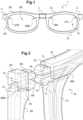
- the spectacle frame 1 has been assembled from two rims, a left rim 2L and a right rim 2R, that have been interconnected by a bridge 3 that is in a central location.
- the bridge 3 is interchangeable thanks to complementary bridge connecting means on each lateral side 17 of the bridge 3 and on the corresponding rim 2R, 2L and that are attachable and detachable allowing to mount and dismount each rim from the bridge 3.
- Each rim is connected/linked laterally to a temple 4 and said temple may include a hinge and in that case, the rim is connected/linked to the hinge that is connected/linked to the temple.
- the temple 4 is also interchangeable thanks to complementary temple connecting means on each lateral side of the rims and on the corresponding temple and that are attachable and detachable allowing to mount and dismount each temple from the rim.
- Each rim 2R, 2L defines centrally a central aperture 5R, 5L in which a lens can be held in place.
- the spectacle frame material is a plastic material, thermoplastic or thermosetting.
- the spectacle frame can be made by molding and/or machining and/or 3D printing.
- each cut/split is made in each rim 2R, 2L.
- two cuts 6TR, 6BR, 6TL, 6BL are made in each rim 2R, 2L, one cut 6BR, 6BL toward the bridge 3 and one cut 6TR, 6TL toward the temple 4. More precisely, for the right rim 2R for instance, a cut 6BR is made toward the bridge 3 and a cut 6TR is made toward the temple 4.
- Each cut 6TR, 6BR, 6TL, 6BL is defined by two opposed and facing ends of the rim and in Figure 1 , each cut is closed, the corresponding ends of the rim being one against the other and thus closing any gap between the ends.
- the cuts can also be closed with a bridge 3 having segments of the rims.
- the cuts 6BR, 6BL toward the bridge 3 are closed because the bridge has been connected to the rims at those locations.
- the cuts 6TR, 6TL toward the temples are closed because the temples have been connected to the rims at those locations.
- the complementary temple connecting means and the complementary bridge connecting means for all those connections between the rims, the bridge and the temples have two main functions, the first one is to link in a stable manner, but being detachable, the two corresponding elements and, the second one, is to close and lock the corresponding cut of the rim.
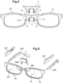
- the bridge has been omitted to be able to better see the central sides of the two rims 2R, 2L where the gaps 2BR, 6BL are located and where they can be connected to the bridge.
- a rim side bridge connecting mean 7R, 8R, 7L, 8L is arranged on the central side of each rim 2R, 2L, stradding the cut 6BR, 6BL, and this rim side bridge connecting mean is one part of the complementary bridge connecting means.
- Each rim 2R, 2L comprises a cut 2BR, 6BL that is shown with a gap opened due to the fact that the bridge is not connected. With the cut 6BR, 6BL having a gap opened, the central aperture 5R, 5L of the rim 2R, 2L has been enlarged.
- the cut 6BR is not straight through the rim 2R but is indented in order to correctly arrange the two ends 14, 15 of the cut when closed and thus avoid an anteroposterior shift of the two ends 14, 15.
- the lower end 14 of the rim 2R comprises a protrusion that can enter a groove of the upper end 15 of the rim 2R, the protrusion and the groove being elongated along the length of the frame in the cut and connecting zone.
- a protrusion and a groove are also made on the ends of the cut 6BL of the left rim 2L.
- same protrusions and grooves are also made for the cuts toward the temples.
- the rim side bridge connecting mean 7R, 8R, 7L, 8L comprise on each end of each cut 6BR, 6BL, a lateral pin 7R, 7L that is horizontal and oriented towards a corresponding lateral side 17 of the bridge 3 to which it is due to be connected.
- the lateral pin 7R, 7L terminates with an enlarged head 8R, 8L constituting a hook.
- a pin 7R, 7L is arranged on each end 14, 15 of the cut 6BR, 6BL and thus a rim have two pins 7R, 7L.
- the bridge 3 is thus configured to accommodate four pins 7R, 7L and their heads 8R, 8L.
- the bridge 3 in the Figure 3 is an integral piece that is pierced with at least two through holes or pits that are perpendicular for accommodating and locking the pins and heads of the rim side bridge connecting mean. Those holes are the bridge side bridge connecting mean of the complementary bridge connecting means.
- the vertical through hole suitable to accommodate the enlarged heads of the pins and defining the receiving recess is split in two separated through holes 10R, 10L, each one for accommodating the heads of the rim side bridge connecting mean of one rim, left or right.
- the horizontal hole suitable to accommodate the pins is not a through hole but it is split in two separated blind holes 9R, 9L, each one for accommodating the pins of the rim side bridge connecting mean of one rim, left or right.
- the pins 7R, 7L of the rim side bridge connecting mean have slight elastic properties to allow some bending when the pins and their heads are inserted in the holes of the bridge side bridge connecting mean and also when they are pulled out.
- a further blind hole 16 (seen by transparency) that opens on the remote face of the bridge 3 in Figure 3 , and that is cylindrical, is arranged in the bridge. That blind hole 16 may be configured to receive a rod that will clamp the heads 8R, 8L locked in position when the rims are connected to the bridge. Without that clamping rod or after its removal, it could be possible to unlock the heads 8R, 8L and dismount the bridge from the rims by pushing them 8R, 8L on both sides of the vertical through holes 10R, 10L to unhook them and then pull apart the rims from the bridge.
- the blind hole 16 is for receiving a rod that is a part of an element comprising nose pads.
- the rod is both a clamping means for the pins + heads and part of a nose pads element.
- the horizontal hole(s) for the pin(s) can be (a) through hole(s) between the two lateral sides 17 of the bridge 3, one such horizontal hole thus receiving from both sides a left and a right pins and heads.
- the vertical hole defining the receiving recess for the enlarged head can instead be a blind hole.
- the vertical hole can be unique for the four heads of the four pins.
- each of the two rims and each lateral side 17 of the bridge comprise clipping complementary bridge connecting means to allow to connect the bridge 3 to the left 2L and right 2R rims of the spectacle frame 1.
- the bridge is arranged straddling the two ends 14, 15 of the cut 6BR, 6BL of the rim.
- the clipping connecting means of the bridge 3 is also the locking means of the cut 6BR, 6BL: when the bridge 3 is connected to the rim 2R, 2L it closes and locks the cut 6BR, 6BL located toward the bridge.
- the complementary bridge connecting means are, for a part, the lateral pins 7R, 7L and their enlarged heads 8R, 8L of the rim side bridge connecting mean.
- the complementary bridge connecting means are, for another part, the holes 9R, 9L, 10R, 10L of the bridge side bridge connecting mean.
- a receiving recess is made in which the enlarged head of the pin can fit and lock the pin in the bridge.
- the receiving recess is made from a vertical through hole 10R, 10L crossing the bottom of the two horizontal holes 9R, 9L accommodating the two pins 7R, 7L.
- the same kind of pins + heads and holes may be used for the complementary temple connecting means used to attach and connect the temples to the rims.
- the pins + heads are on the rim and the holes on the temple.
- the complementary temple connecting means are straddling the ends of the rim cut and are also used to close and lock said cut in a similar way as for the cut 6BR, 6BL toward the bridge.
- the last solution of same kind of pins + heads for the rim side bridge connecting mean and for the rim side temple connecting mean is particularly interesting because it allows making rims that are identical for the right or left eye and that are totally interchangeable even if the rims are incurved. Thanks to such a solution, the inventory of parts of the eyewear is much reduced because there is only one kind of rim that can be used on right or left eye.
- the rim can have only one cut located toward the bridge and that both the bridge and the temple may be attachable or even exchangeable, the complementary temple connecting means and the complementary bridge connecting means being similar but no cut/split being located toward the temple.
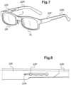
- FIG. 5 Another embodiment of the invention is now described in relation to figure 5 .
- the gap of each cut located toward the bridge is closed thanks to a segment 11R, 11L of the corresponding rim 2R, 2L integral to the bridge 3.
- two interchangeable bridges 3 are represented and have two different lengths to modify the interpupillary distance of the spectacle frame.
- Nose pads 13 are also represented on the bridges 3.
- Same kinds or other types of nose pads may be arranged on the bridge of the spectacle frame of the previous Figures 1 to 4 if the shape of their bridge and rims are not adapted to directly fit to a nose.
- the nose pads may be individual pads arranged on the bridge or a specific element having two nose pads and that is arranged on the bridge.
- the embodiment of spectacle frame represented on the figures 6 to 8 has only one cut 6BR, 6BL of the rim 2R, 2L and those cuts are closed and locked by the installation of the bridge between the two rims 2R, 2L. Thanks to only one cut 6BR, 6BL on each rim 2R, 2L there is no risk of loosing a part of a rim because it remains integral even if the cut is open for the insertion or removal of the lens.
- Each temple of this spectacle frame can be adjusted in length and is made of two parts, a front part 22F connectable to the corresponding rim and preferably articulated to it, and a rear part 22R.
- Those two parts 22F, 22R can slide one relative to the other.
- the means for adjusting and locking the two parts are better visible : a rim 22P of the rear part 22P can slide and be locked in an indexed groove 22N of the front part 22F.
- a front segment of the rear part 22R is entered in a channel or a tunnel of a rear segment of the front part 22F.
- Other adjusting and release locking means may be used.
- the first end of the rim cut can have complementary bridge locking means with the bridge for the connection of the rim to the bridge and the second end of the cut can have connecting and locking means complementary to ones of the first end of the rim.
Landscapes
- Physics & Mathematics (AREA)
- Health & Medical Sciences (AREA)
- General Physics & Mathematics (AREA)
- Ophthalmology & Optometry (AREA)
- Optics & Photonics (AREA)
- Eyeglasses (AREA)
Claims (12)
- Brillengestell (1), umfassend ein Paar glashaltende Ringe (2R, 2L), die über eine Brücke (3) miteinander verbunden sind,wobei jeder Ring (2R, 2L) dazu geeignet ist, ein Glas in einer zentralen Öffnung (5R; 5L) des Ringes (2R, 2L) zu umschließen und zu halten,wobei jeder Ring (2R, 2L) seitlich mit einem Bügel (4, 21R, 21L, 22) gekoppelt ist,wobei jeder Ring (2R, 2L) einen Schnitt (6BR, 6BL) zwischen zwei gegenüberliegenden und einander zugewandten Enden des Ringes aufweist, wobei der Schnitt erlaubt, die zentrale Öffnung (5R, 5L) durch Öffnen eines Spalts zwischen den zwei Enden des Schnitts des Ringes auszudehnen oder zurückzuziehen und die zentrale Öffnung durch Schließen des Schnitts (6BR, 6BL) seitlich zu schließen,wobei das Brillengestell (1) ferner ein Verriegelungsmittel umfasst, das es erlaubt, den Schnitt (6BR, 6BL) des Ringes (2R, 2L) zu schließen und zu verriegeln,wobei die Brücke an den Ringen (2R, 2L) anbringbar ist, um die Anbringung einer Brücke (3) zu erlauben, die unter Brücken mit verschiedenen Formen und/oder Größen und/oder Verzierungen ausgewählt wurde, um das Brillengestell an verschiedene morphologische Merkmale von Trägern und/oder Entscheidungen der Träger anzupassen, und wobei die Ringe (2R, 2L) und die Brücke (3) komplementäre Brückenverbindungsmittel (7R, 8R, 7L, 8L) (9R, 10R, 9L, 10L) umfassen, um die Brücke (3) an jedem Ring (2R, 2L) anzubringen und damit zu verbinden, wobei sich in jedem Ring (2R, 2L) der Schnitt (6BR, 6BL) in Richtung der Brücke befindet und die komplementären Brückenverbindungsmittel ebenfalls die Verriegelungsmittel des Schnitts (6BR, 6BL) des Ringes (2R, 2L) sind, wobei die komplementären Brückenverbindungsmittel derart ausgelegt sind, dass, in dem geschlossenen und verriegelten Zustand des Schnitts (6BR, 6BL) die entsprechenden Verbindungsmittel den geschlossenen Schnitt (6BR, 6BL) überspannen,wobei die komplementären Brückenverbindungsmittel ein Brückenverbindungsmittel auf der Brückenseite und ein Brückenverbindungsmittel auf der Ringseite sind, dadurch gekennzeichnet, dass die zwei Enden des Schnitts aneinander anliegen, wenn der Schnitt geschlossen ist, undwobei das Brückenverbindungsmittel der Ringseite an jedem Ende des Ringschnitts mindestens einen seitlichen Stift (7R, 7L) mit einem vergrößerten Kopf (8R, 8L) umfasst, wobei der Stift in Richtung einer entsprechenden lateralen Seite der Brücke ausgerichtet ist,wobei das Brückenverbindungsmittel der Brückenseite für jeden Stift ein entsprechendes Loch zum Aufnehmen des entsprechenden Stifts und seines vergrößerten Kopfes umfasst, wobei das Loch eine kopfaufnehmende Aussparung aufweist, wobei sich die kopfaufnehmende Aussparung auf der Höhe befindet, die von dem Stiftkopf in der Brücke erreicht wird, wenn die Brücke mit dem Ring verbunden wird, und der vergrößerte Kopf des Stifts in die kopfaufnehmende Aussparung passen und darin verriegelt werden kann, um den Stift zu verriegeln, undwobei in der Brücke jedes Loch für den Stift ein horizontales Loch (9R, 9L) ist und die entsprechende kopfaufnehmende Aussparung eine Vertiefung (10R, 10L) ist, die an einer freien Fläche der Brücke geöffnet ist und das horizontale Loch überquert.
- Brillengestell nach Anspruch 1, wobei die Brücke ebenfalls von den Ringen (2R, 2L) abnehmbar ist, um einen Austausch der Brücke mit einer anderen Brücke zu erlauben, die unter Brücken mit verschiedenen Formen und/oder Größen und/oder Verzierungen ausgewählt wurde, um das Brillengestell an verschiedene morphologische Merkmale des Trägers oder der Entscheidung des Trägers anzupassen.
- Brillengestell nach Anspruch 1 oder Anspruch 2, wobei jeder Bügel an dem entsprechenden Ring (2R, 2L) (19R, 20R) (19L, 20L) anbringbar ist, wobei der Bügel und der Ring (2R, 2L) (19R, 20R) (19L, 20L) komplementäre Bügelverbindungsmittel umfassen, um den Bügel an dem Ring (2R, 2L) (19R, 20R) (19L, 20L) anzubringen und damit zu verbinden.
- Brillengestell nach einem der Ansprüche 1 bis 3, wobei das komplementäre Brückenverbindungsmittel und das etwaige komplementäre Bügelverbindungsmittel Klemmmittel sind.
- Brillengestell nach einem der Ansprüche 1 bis 4, wobei die Brücke Verbindungsmittel zum Verbinden zweier separater Nasenpads oder einem Paar aneinander befestigter Nasenpads umfasst.
- Brillengestell nach einem der Ansprüche 1 bis 5, wobei das Paar glashaltende Ringe identisch ist, so dass das in die Ringe aufgenommene rechte und linke Glas austauschbar sind.
- Brillengestell nach einem der Ansprüche 1 bis 6, wobei die Länge des Bügels einstellbar ist.
- Brillengestell nach Anspruch 7, wobei jeder Bügel aus mindestens zwei Teilen besteht, die bezogen aufeinander gleiten können, um die Länge des Bügels einzustellen.
- Brillengestell nach Anspruch 8, wobei die mindestens zwei Teile des Bügels komplementäre lösbare Verriegelungsmittel umfassen, die die Längeneinstellung und die Verriegelung der relativen Position der mindestens zwei Teile erlauben, sobald die Länge eingestellt ist.
- Brillengestellteilesatz, wobei es Artikel umfasst, die speziell zum Herstellen eines Brillengestells nach einem der Ansprüche 1 bis 9 geformt sind, wobei diese Artikel sind:- ein Paar glashaltende Ringe (2R, 2L), wobei jeder Ring (2R, 2L) seitlich mit einem Bügel gekoppelt ist und einen Schnitt (6BR, 6BL) aufweist, auf der Brückenseite des glashaltenden Rings,- ein Satz Brücken, wobei die Brücken mindestens an den Ringen (2R, 2L) anbringbar sind.
- Brillengestellteilesatz nach Anspruch 10, wobei es einen Satz Bügel umfasst, wobei die Bügel mindestens an dem Ring (2R, 2L) anbringbar sind.
- Brille, umfassend ein Brillengestell nach einem der Ansprüche 1 bis 9 und ein Paar Gläser in den Ringen (2R, 2L).
Applications Claiming Priority (2)
| Application Number | Priority Date | Filing Date | Title |
|---|---|---|---|
| EP17161456 | 2017-03-16 | ||
| PCT/EP2018/056688 WO2018167279A1 (en) | 2017-03-16 | 2018-03-16 | Spectacle frame with cut rims and attachable bridge, kit of parts and eyewear |
Publications (2)
| Publication Number | Publication Date |
|---|---|
| EP3596535A1 EP3596535A1 (de) | 2020-01-22 |
| EP3596535B1 true EP3596535B1 (de) | 2025-05-28 |
Family
ID=58358435
Family Applications (1)
| Application Number | Title | Priority Date | Filing Date |
|---|---|---|---|
| EP18712182.7A Active EP3596535B1 (de) | 2017-03-16 | 2018-03-16 | Brillengestell mit geschnittenen ringen und anbringbarer brücke, teilesatz und brille |
Country Status (4)
| Country | Link |
|---|---|
| US (1) | US11249324B2 (de) |
| EP (1) | EP3596535B1 (de) |
| CN (2) | CN108627998B (de) |
| WO (1) | WO2018167279A1 (de) |
Families Citing this family (9)
| Publication number | Priority date | Publication date | Assignee | Title |
|---|---|---|---|---|
| DK180074B1 (da) | 2019-02-11 | 2020-03-25 | Lindberg A/S | Selvlåsende brillesystem |
| US11029531B2 (en) | 2019-02-18 | 2021-06-08 | Amanda Carrier | Eyeglass frame lens lock |
| DE102020200012A1 (de) * | 2020-01-03 | 2021-07-08 | Robert Bosch Gesellschaft mit beschränkter Haftung | Datenbrille |
| CN115524863A (zh) * | 2022-04-29 | 2022-12-27 | 陈淑文 | 一种眼镜 |
| WO2024130047A2 (en) * | 2022-12-15 | 2024-06-20 | Pose pets, LLC | Quadruped optical system |
| IT202300005400A1 (it) * | 2023-03-27 | 2024-09-27 | Paolo Todoverto | Montatura di occhiale ad elementi intercambiabili e suo metodo di assemblaggio a puzzle |
| US20240402513A1 (en) * | 2023-06-02 | 2024-12-05 | Google Llc | Augmented reality eyewear displays with insertable prescription lenses |
| FR3156551A1 (fr) * | 2023-12-06 | 2025-06-13 | Rondot Optique | Monture de lunette |
| CN119024574A (zh) * | 2024-10-28 | 2024-11-26 | 温州市珍视光学有限公司 | 一种镜架以及镜框工艺 |
Family Cites Families (10)
| Publication number | Priority date | Publication date | Assignee | Title |
|---|---|---|---|---|
| CN2342384Y (zh) * | 1997-08-07 | 1999-10-06 | 郁家心 | 可调眼镜架 |
| US6454406B1 (en) * | 2002-03-12 | 2002-09-24 | Pao-Shoei Guo | Adjustable temple mounting arrangement |
| US20030223032A1 (en) * | 2002-05-30 | 2003-12-04 | Mario Gagnon | Eyewear and system |
| US7066593B1 (en) * | 2004-12-22 | 2006-06-27 | High Rainbow Ent. Co., Ltd. | Eyeglasses frame assembly |
| TW200947015A (en) | 2008-05-09 | 2009-11-16 | Qef Design Corp | Fast detachable eyeglasses |
| CN201242621Y (zh) * | 2008-08-13 | 2009-05-20 | 李方旭 | 一种可调眼镜腿 |
| KR20130001568U (ko) * | 2011-08-29 | 2013-03-08 | 김원식 | 안경프레임 고정구조 |
| TW201439637A (zh) * | 2013-02-13 | 2014-10-16 | Planet Vision 60 Co Ltd | 眼鏡 |
| CN204360040U (zh) * | 2015-01-16 | 2015-05-27 | 金陵科技学院 | 螺纹式自动调节镜眼距的专属眼镜 |
| EP3081981A1 (de) * | 2015-04-17 | 2016-10-19 | Essilor International (Compagnie Generale D'optique) | An einen brillenträger angepasste brille, brillen-kit zur herstellung einer solchen brille und entsprechende herstellungsmethoden |
-
2018
- 2018-03-14 CN CN201810209771.XA patent/CN108627998B/zh active Active
- 2018-03-14 CN CN201820349537.2U patent/CN208689294U/zh active Active
- 2018-03-16 WO PCT/EP2018/056688 patent/WO2018167279A1/en not_active Ceased
- 2018-03-16 EP EP18712182.7A patent/EP3596535B1/de active Active
- 2018-03-16 US US16/493,908 patent/US11249324B2/en not_active Expired - Fee Related
Also Published As
| Publication number | Publication date |
|---|---|
| CN208689294U (zh) | 2019-04-02 |
| EP3596535A1 (de) | 2020-01-22 |
| WO2018167279A1 (en) | 2018-09-20 |
| CN108627998A (zh) | 2018-10-09 |
| BR212019017730U2 (pt) | 2019-12-17 |
| US11249324B2 (en) | 2022-02-15 |
| CN108627998B (zh) | 2022-03-15 |
| US20200089022A1 (en) | 2020-03-19 |
Similar Documents
| Publication | Publication Date | Title |
|---|---|---|
| US11249324B2 (en) | Spectacle frame with cut rims and attachable bridge, kit of parts and eyewear | |
| US20160377890A1 (en) | Exchangeable eye glass members | |
| US8992009B2 (en) | Module eye glasses | |
| US7585069B2 (en) | Customization eyewear system for eyewear with multi-compartments | |
| US10718955B2 (en) | Device for connecting spectacle temples to the frame front | |
| US7370961B2 (en) | Interchangeable eyewear assembly | |
| US7690786B2 (en) | Device for changing bridges, side arms and browbars of rimless spectacles and for changing bridges and side arms of metallic and plastic spectacle frames | |
| WO1995013558A1 (en) | Eyewear having interchangeable lenses | |
| US6227665B1 (en) | Sport eyeglasses having removable lenses | |
| US20200133032A1 (en) | Glasses with Removable Eye Shields | |
| CN101023390A (zh) | 耐用型眼镜架组件 | |
| US3941461A (en) | Hinge attached to the split ends means for aligning an eyeglass frame at the split ends thereof and also the front | |
| US10739616B2 (en) | Detachable spectacle frame | |
| US20160231588A1 (en) | Interchangeabal Eyewear | |
| JPH05504849A (ja) | 眼鏡 | |
| KR20220002437U (ko) | 렌즈 교환이 가능한 단일 렌즈 안경 | |
| US5880806A (en) | Eyewear frame construction | |
| AU2013100849A4 (en) | Eyeglass bridge assembly | |
| US5777714A (en) | Eyewear frame construction | |
| US2831393A (en) | Spectacle mounting | |
| KR102832855B1 (ko) | 자기-잠금 안경 시스템 | |
| BR212019017730Y1 (pt) | Armação para óculos compreendendo aros de corte e uma ponte conectável, kit de peças e par de óculos | |
| US10451899B2 (en) | Temple cover for eye glasses | |
| US10295840B2 (en) | Rimless glasses frame including at least one flexible clamping element | |
| JP3688247B2 (ja) | フリーサイズ眼鏡 |
Legal Events
| Date | Code | Title | Description |
|---|---|---|---|
| STAA | Information on the status of an ep patent application or granted ep patent |
Free format text: STATUS: UNKNOWN |
|
| STAA | Information on the status of an ep patent application or granted ep patent |
Free format text: STATUS: THE INTERNATIONAL PUBLICATION HAS BEEN MADE |
|
| PUAI | Public reference made under article 153(3) epc to a published international application that has entered the european phase |
Free format text: ORIGINAL CODE: 0009012 |
|
| STAA | Information on the status of an ep patent application or granted ep patent |
Free format text: STATUS: REQUEST FOR EXAMINATION WAS MADE |
|
| 17P | Request for examination filed |
Effective date: 20190916 |
|
| AK | Designated contracting states |
Kind code of ref document: A1 Designated state(s): AL AT BE BG CH CY CZ DE DK EE ES FI FR GB GR HR HU IE IS IT LI LT LU LV MC MK MT NL NO PL PT RO RS SE SI SK SM TR |
|
| AX | Request for extension of the european patent |
Extension state: BA ME |
|
| DAV | Request for validation of the european patent (deleted) | ||
| DAX | Request for extension of the european patent (deleted) | ||
| STAA | Information on the status of an ep patent application or granted ep patent |
Free format text: STATUS: EXAMINATION IS IN PROGRESS |
|
| 17Q | First examination report despatched |
Effective date: 20221130 |
|
| P01 | Opt-out of the competence of the unified patent court (upc) registered |
Effective date: 20230525 |
|
| GRAP | Despatch of communication of intention to grant a patent |
Free format text: ORIGINAL CODE: EPIDOSNIGR1 |
|
| STAA | Information on the status of an ep patent application or granted ep patent |
Free format text: STATUS: GRANT OF PATENT IS INTENDED |
|
| INTG | Intention to grant announced |
Effective date: 20241218 |
|
| GRAS | Grant fee paid |
Free format text: ORIGINAL CODE: EPIDOSNIGR3 |
|
| GRAA | (expected) grant |
Free format text: ORIGINAL CODE: 0009210 |
|
| STAA | Information on the status of an ep patent application or granted ep patent |
Free format text: STATUS: THE PATENT HAS BEEN GRANTED |
|
| AK | Designated contracting states |
Kind code of ref document: B1 Designated state(s): AL AT BE BG CH CY CZ DE DK EE ES FI FR GB GR HR HU IE IS IT LI LT LU LV MC MK MT NL NO PL PT RO RS SE SI SK SM TR |
|
| REG | Reference to a national code |
Ref country code: GB Ref legal event code: FG4D |
|
| REG | Reference to a national code |
Ref country code: CH Ref legal event code: EP |
|
| REG | Reference to a national code |
Ref country code: IE Ref legal event code: FG4D Ref country code: DE Ref legal event code: R096 Ref document number: 602018082260 Country of ref document: DE |
|
| REG | Reference to a national code |
Ref country code: NL Ref legal event code: MP Effective date: 20250528 |
|
| PG25 | Lapsed in a contracting state [announced via postgrant information from national office to epo] |
Ref country code: FI Free format text: LAPSE BECAUSE OF FAILURE TO SUBMIT A TRANSLATION OF THE DESCRIPTION OR TO PAY THE FEE WITHIN THE PRESCRIBED TIME-LIMIT Effective date: 20250528 Ref country code: ES Free format text: LAPSE BECAUSE OF FAILURE TO SUBMIT A TRANSLATION OF THE DESCRIPTION OR TO PAY THE FEE WITHIN THE PRESCRIBED TIME-LIMIT Effective date: 20250528 |
|
| REG | Reference to a national code |
Ref country code: LT Ref legal event code: MG9D |
|
| PG25 | Lapsed in a contracting state [announced via postgrant information from national office to epo] |
Ref country code: NO Free format text: LAPSE BECAUSE OF FAILURE TO SUBMIT A TRANSLATION OF THE DESCRIPTION OR TO PAY THE FEE WITHIN THE PRESCRIBED TIME-LIMIT Effective date: 20250828 Ref country code: GR Free format text: LAPSE BECAUSE OF FAILURE TO SUBMIT A TRANSLATION OF THE DESCRIPTION OR TO PAY THE FEE WITHIN THE PRESCRIBED TIME-LIMIT Effective date: 20250829 |
|
| PG25 | Lapsed in a contracting state [announced via postgrant information from national office to epo] |
Ref country code: PL Free format text: LAPSE BECAUSE OF FAILURE TO SUBMIT A TRANSLATION OF THE DESCRIPTION OR TO PAY THE FEE WITHIN THE PRESCRIBED TIME-LIMIT Effective date: 20250528 Ref country code: NL Free format text: LAPSE BECAUSE OF FAILURE TO SUBMIT A TRANSLATION OF THE DESCRIPTION OR TO PAY THE FEE WITHIN THE PRESCRIBED TIME-LIMIT Effective date: 20250528 |
|
| PG25 | Lapsed in a contracting state [announced via postgrant information from national office to epo] |
Ref country code: BG Free format text: LAPSE BECAUSE OF FAILURE TO SUBMIT A TRANSLATION OF THE DESCRIPTION OR TO PAY THE FEE WITHIN THE PRESCRIBED TIME-LIMIT Effective date: 20250528 |
|
| PG25 | Lapsed in a contracting state [announced via postgrant information from national office to epo] |
Ref country code: HR Free format text: LAPSE BECAUSE OF FAILURE TO SUBMIT A TRANSLATION OF THE DESCRIPTION OR TO PAY THE FEE WITHIN THE PRESCRIBED TIME-LIMIT Effective date: 20250528 |
|
| PG25 | Lapsed in a contracting state [announced via postgrant information from national office to epo] |
Ref country code: RS Free format text: LAPSE BECAUSE OF FAILURE TO SUBMIT A TRANSLATION OF THE DESCRIPTION OR TO PAY THE FEE WITHIN THE PRESCRIBED TIME-LIMIT Effective date: 20250828 |
|
| PG25 | Lapsed in a contracting state [announced via postgrant information from national office to epo] |
Ref country code: IS Free format text: LAPSE BECAUSE OF FAILURE TO SUBMIT A TRANSLATION OF THE DESCRIPTION OR TO PAY THE FEE WITHIN THE PRESCRIBED TIME-LIMIT Effective date: 20250928 |
|
| PG25 | Lapsed in a contracting state [announced via postgrant information from national office to epo] |
Ref country code: LV Free format text: LAPSE BECAUSE OF FAILURE TO SUBMIT A TRANSLATION OF THE DESCRIPTION OR TO PAY THE FEE WITHIN THE PRESCRIBED TIME-LIMIT Effective date: 20250528 |
|
| REG | Reference to a national code |
Ref country code: AT Ref legal event code: MK05 Ref document number: 1798919 Country of ref document: AT Kind code of ref document: T Effective date: 20250528 |
|
| PG25 | Lapsed in a contracting state [announced via postgrant information from national office to epo] |
Ref country code: SM Free format text: LAPSE BECAUSE OF FAILURE TO SUBMIT A TRANSLATION OF THE DESCRIPTION OR TO PAY THE FEE WITHIN THE PRESCRIBED TIME-LIMIT Effective date: 20250528 Ref country code: AT Free format text: LAPSE BECAUSE OF FAILURE TO SUBMIT A TRANSLATION OF THE DESCRIPTION OR TO PAY THE FEE WITHIN THE PRESCRIBED TIME-LIMIT Effective date: 20250528 Ref country code: DK Free format text: LAPSE BECAUSE OF FAILURE TO SUBMIT A TRANSLATION OF THE DESCRIPTION OR TO PAY THE FEE WITHIN THE PRESCRIBED TIME-LIMIT Effective date: 20250528 |
|
| PG25 | Lapsed in a contracting state [announced via postgrant information from national office to epo] |
Ref country code: CZ Free format text: LAPSE BECAUSE OF FAILURE TO SUBMIT A TRANSLATION OF THE DESCRIPTION OR TO PAY THE FEE WITHIN THE PRESCRIBED TIME-LIMIT Effective date: 20250528 |
|
| PG25 | Lapsed in a contracting state [announced via postgrant information from national office to epo] |
Ref country code: EE Free format text: LAPSE BECAUSE OF FAILURE TO SUBMIT A TRANSLATION OF THE DESCRIPTION OR TO PAY THE FEE WITHIN THE PRESCRIBED TIME-LIMIT Effective date: 20250528 |
|
| PG25 | Lapsed in a contracting state [announced via postgrant information from national office to epo] |
Ref country code: RO Free format text: LAPSE BECAUSE OF FAILURE TO SUBMIT A TRANSLATION OF THE DESCRIPTION OR TO PAY THE FEE WITHIN THE PRESCRIBED TIME-LIMIT Effective date: 20250528 Ref country code: SK Free format text: LAPSE BECAUSE OF FAILURE TO SUBMIT A TRANSLATION OF THE DESCRIPTION OR TO PAY THE FEE WITHIN THE PRESCRIBED TIME-LIMIT Effective date: 20250528 |
|
| PG25 | Lapsed in a contracting state [announced via postgrant information from national office to epo] |
Ref country code: IT Free format text: LAPSE BECAUSE OF FAILURE TO SUBMIT A TRANSLATION OF THE DESCRIPTION OR TO PAY THE FEE WITHIN THE PRESCRIBED TIME-LIMIT Effective date: 20250528 |
|
| REG | Reference to a national code |
Ref country code: DE Ref legal event code: R097 Ref document number: 602018082260 Country of ref document: DE |
|
| PLBE | No opposition filed within time limit |
Free format text: ORIGINAL CODE: 0009261 |
|
| STAA | Information on the status of an ep patent application or granted ep patent |
Free format text: STATUS: NO OPPOSITION FILED WITHIN TIME LIMIT |
|
| REG | Reference to a national code |
Ref country code: CH Ref legal event code: L10 Free format text: ST27 STATUS EVENT CODE: U-0-0-L10-L00 (AS PROVIDED BY THE NATIONAL OFFICE) Effective date: 20260409 |
|
| 26N | No opposition filed |
Effective date: 20260303 |