EP3596443B1 - Dissolved gas analysis devices, systems, and methods - Google Patents
Dissolved gas analysis devices, systems, and methods Download PDFInfo
- Publication number
- EP3596443B1 EP3596443B1 EP18767035.1A EP18767035A EP3596443B1 EP 3596443 B1 EP3596443 B1 EP 3596443B1 EP 18767035 A EP18767035 A EP 18767035A EP 3596443 B1 EP3596443 B1 EP 3596443B1
- Authority
- EP
- European Patent Office
- Prior art keywords
- gas
- transformer
- fluid
- mpa
- extraction
- Prior art date
- Legal status (The legal status is an assumption and is not a legal conclusion. Google has not performed a legal analysis and makes no representation as to the accuracy of the status listed.)
- Active
Links
Images

Classifications
-
- G—PHYSICS
- G01—MEASURING; TESTING
- G01N—INVESTIGATING OR ANALYSING MATERIALS BY DETERMINING THEIR CHEMICAL OR PHYSICAL PROPERTIES
- G01N1/00—Sampling; Preparing specimens for investigation
- G01N1/02—Devices for withdrawing samples
- G01N1/22—Devices for withdrawing samples in the gaseous state
- G01N1/2202—Devices for withdrawing samples in the gaseous state involving separation of sample components during sampling
- G01N1/2205—Devices for withdrawing samples in the gaseous state involving separation of sample components during sampling with filters
-
- G—PHYSICS
- G01—MEASURING; TESTING
- G01N—INVESTIGATING OR ANALYSING MATERIALS BY DETERMINING THEIR CHEMICAL OR PHYSICAL PROPERTIES
- G01N1/00—Sampling; Preparing specimens for investigation
- G01N1/02—Devices for withdrawing samples
- G01N1/22—Devices for withdrawing samples in the gaseous state
- G01N1/2226—Sampling from a closed space, e.g. food package, head space
-
- G—PHYSICS
- G01—MEASURING; TESTING
- G01N—INVESTIGATING OR ANALYSING MATERIALS BY DETERMINING THEIR CHEMICAL OR PHYSICAL PROPERTIES
- G01N1/00—Sampling; Preparing specimens for investigation
- G01N1/02—Devices for withdrawing samples
- G01N1/22—Devices for withdrawing samples in the gaseous state
- G01N1/24—Suction devices
-
- G—PHYSICS
- G01—MEASURING; TESTING
- G01N—INVESTIGATING OR ANALYSING MATERIALS BY DETERMINING THEIR CHEMICAL OR PHYSICAL PROPERTIES
- G01N21/00—Investigating or analysing materials by the use of optical means, i.e. using sub-millimetre waves, infrared, visible or ultraviolet light
- G01N21/01—Arrangements or apparatus for facilitating the optical investigation
- G01N21/11—Filling or emptying of cuvettes
-
- G—PHYSICS
- G01—MEASURING; TESTING
- G01N—INVESTIGATING OR ANALYSING MATERIALS BY DETERMINING THEIR CHEMICAL OR PHYSICAL PROPERTIES
- G01N21/00—Investigating or analysing materials by the use of optical means, i.e. using sub-millimetre waves, infrared, visible or ultraviolet light
- G01N21/17—Systems in which incident light is modified in accordance with the properties of the material investigated
- G01N21/25—Colour; Spectral properties, i.e. comparison of effect of material on the light at two or more different wavelengths or wavelength bands
- G01N21/31—Investigating relative effect of material at wavelengths characteristic of specific elements or molecules, e.g. atomic absorption spectrometry
- G01N21/35—Investigating relative effect of material at wavelengths characteristic of specific elements or molecules, e.g. atomic absorption spectrometry using infrared light
- G01N21/3504—Investigating relative effect of material at wavelengths characteristic of specific elements or molecules, e.g. atomic absorption spectrometry using infrared light for analysing gases, e.g. multi-gas analysis
-
- G—PHYSICS
- G01—MEASURING; TESTING
- G01N—INVESTIGATING OR ANALYSING MATERIALS BY DETERMINING THEIR CHEMICAL OR PHYSICAL PROPERTIES
- G01N33/00—Investigating or analysing materials by specific methods not covered by groups G01N1/00 - G01N31/00
- G01N33/26—Oils; Viscous liquids; Paints; Inks
- G01N33/28—Oils, i.e. hydrocarbon liquids
- G01N33/2835—Specific substances contained in the oils or fuels
- G01N33/2841—Gas in oils, e.g. hydrogen in insulating oils
-
- H—ELECTRICITY
- H01—ELECTRIC ELEMENTS
- H01F—MAGNETS; INDUCTANCES; TRANSFORMERS; SELECTION OF MATERIALS FOR THEIR MAGNETIC PROPERTIES
- H01F27/00—Details of transformers or inductances, in general
- H01F27/08—Cooling; Ventilating
- H01F27/10—Liquid cooling
-
- H—ELECTRICITY
- H01—ELECTRIC ELEMENTS
- H01F—MAGNETS; INDUCTANCES; TRANSFORMERS; SELECTION OF MATERIALS FOR THEIR MAGNETIC PROPERTIES
- H01F27/00—Details of transformers or inductances, in general
- H01F27/28—Coils; Windings; Conductive connections
- H01F27/32—Insulating of coils, windings, or parts thereof
- H01F27/321—Insulating of coils, windings, or parts thereof using a fluid for insulating purposes only
-
- H—ELECTRICITY
- H01—ELECTRIC ELEMENTS
- H01F—MAGNETS; INDUCTANCES; TRANSFORMERS; SELECTION OF MATERIALS FOR THEIR MAGNETIC PROPERTIES
- H01F27/00—Details of transformers or inductances, in general
- H01F27/40—Structural association with built-in electric component, e.g. fuse
- H01F27/402—Association of measuring or protective means
-
- G—PHYSICS
- G01—MEASURING; TESTING
- G01N—INVESTIGATING OR ANALYSING MATERIALS BY DETERMINING THEIR CHEMICAL OR PHYSICAL PROPERTIES
- G01N1/00—Sampling; Preparing specimens for investigation
- G01N1/02—Devices for withdrawing samples
- G01N1/22—Devices for withdrawing samples in the gaseous state
- G01N1/2247—Sampling from a flowing stream of gas
- G01N2001/2267—Sampling from a flowing stream of gas separating gas from liquid, e.g. bubbles
-
- G—PHYSICS
- G01—MEASURING; TESTING
- G01N—INVESTIGATING OR ANALYSING MATERIALS BY DETERMINING THEIR CHEMICAL OR PHYSICAL PROPERTIES
- G01N21/00—Investigating or analysing materials by the use of optical means, i.e. using sub-millimetre waves, infrared, visible or ultraviolet light
- G01N21/17—Systems in which incident light is modified in accordance with the properties of the material investigated
- G01N21/1702—Systems in which incident light is modified in accordance with the properties of the material investigated with opto-acoustic detection, e.g. for gases or analysing solids
- G01N2021/1704—Systems in which incident light is modified in accordance with the properties of the material investigated with opto-acoustic detection, e.g. for gases or analysing solids in gases
-
- G—PHYSICS
- G01—MEASURING; TESTING
- G01N—INVESTIGATING OR ANALYSING MATERIALS BY DETERMINING THEIR CHEMICAL OR PHYSICAL PROPERTIES
- G01N21/00—Investigating or analysing materials by the use of optical means, i.e. using sub-millimetre waves, infrared, visible or ultraviolet light
- G01N21/17—Systems in which incident light is modified in accordance with the properties of the material investigated
- G01N21/25—Colour; Spectral properties, i.e. comparison of effect of material on the light at two or more different wavelengths or wavelength bands
- G01N21/31—Investigating relative effect of material at wavelengths characteristic of specific elements or molecules, e.g. atomic absorption spectrometry
- G01N21/35—Investigating relative effect of material at wavelengths characteristic of specific elements or molecules, e.g. atomic absorption spectrometry using infrared light
- G01N2021/3595—Investigating relative effect of material at wavelengths characteristic of specific elements or molecules, e.g. atomic absorption spectrometry using infrared light using FTIR
-
- G—PHYSICS
- G01—MEASURING; TESTING
- G01N—INVESTIGATING OR ANALYSING MATERIALS BY DETERMINING THEIR CHEMICAL OR PHYSICAL PROPERTIES
- G01N21/00—Investigating or analysing materials by the use of optical means, i.e. using sub-millimetre waves, infrared, visible or ultraviolet light
- G01N21/17—Systems in which incident light is modified in accordance with the properties of the material investigated
- G01N21/25—Colour; Spectral properties, i.e. comparison of effect of material on the light at two or more different wavelengths or wavelength bands
- G01N21/31—Investigating relative effect of material at wavelengths characteristic of specific elements or molecules, e.g. atomic absorption spectrometry
- G01N21/39—Investigating relative effect of material at wavelengths characteristic of specific elements or molecules, e.g. atomic absorption spectrometry using tunable lasers
- G01N2021/391—Intracavity sample
-
- G—PHYSICS
- G01—MEASURING; TESTING
- G01N—INVESTIGATING OR ANALYSING MATERIALS BY DETERMINING THEIR CHEMICAL OR PHYSICAL PROPERTIES
- G01N21/00—Investigating or analysing materials by the use of optical means, i.e. using sub-millimetre waves, infrared, visible or ultraviolet light
- G01N21/17—Systems in which incident light is modified in accordance with the properties of the material investigated
- G01N21/25—Colour; Spectral properties, i.e. comparison of effect of material on the light at two or more different wavelengths or wavelength bands
- G01N21/31—Investigating relative effect of material at wavelengths characteristic of specific elements or molecules, e.g. atomic absorption spectrometry
- G01N21/39—Investigating relative effect of material at wavelengths characteristic of specific elements or molecules, e.g. atomic absorption spectrometry using tunable lasers
- G01N2021/396—Type of laser source
- G01N2021/399—Diode laser
-
- G—PHYSICS
- G01—MEASURING; TESTING
- G01N—INVESTIGATING OR ANALYSING MATERIALS BY DETERMINING THEIR CHEMICAL OR PHYSICAL PROPERTIES
- G01N21/00—Investigating or analysing materials by the use of optical means, i.e. using sub-millimetre waves, infrared, visible or ultraviolet light
- G01N21/01—Arrangements or apparatus for facilitating the optical investigation
- G01N21/03—Cuvette constructions
- G01N21/031—Multipass arrangements
-
- G—PHYSICS
- G01—MEASURING; TESTING
- G01N—INVESTIGATING OR ANALYSING MATERIALS BY DETERMINING THEIR CHEMICAL OR PHYSICAL PROPERTIES
- G01N21/00—Investigating or analysing materials by the use of optical means, i.e. using sub-millimetre waves, infrared, visible or ultraviolet light
- G01N21/17—Systems in which incident light is modified in accordance with the properties of the material investigated
- G01N21/25—Colour; Spectral properties, i.e. comparison of effect of material on the light at two or more different wavelengths or wavelength bands
- G01N21/31—Investigating relative effect of material at wavelengths characteristic of specific elements or molecules, e.g. atomic absorption spectrometry
- G01N21/33—Investigating relative effect of material at wavelengths characteristic of specific elements or molecules, e.g. atomic absorption spectrometry using ultraviolet light
-
- G—PHYSICS
- G01—MEASURING; TESTING
- G01N—INVESTIGATING OR ANALYSING MATERIALS BY DETERMINING THEIR CHEMICAL OR PHYSICAL PROPERTIES
- G01N21/00—Investigating or analysing materials by the use of optical means, i.e. using sub-millimetre waves, infrared, visible or ultraviolet light
- G01N21/62—Systems in which the material investigated is excited whereby it emits light or causes a change in wavelength of the incident light
- G01N21/63—Systems in which the material investigated is excited whereby it emits light or causes a change in wavelength of the incident light optically excited
- G01N21/65—Raman scattering
-
- H—ELECTRICITY
- H01—ELECTRIC ELEMENTS
- H01F—MAGNETS; INDUCTANCES; TRANSFORMERS; SELECTION OF MATERIALS FOR THEIR MAGNETIC PROPERTIES
- H01F27/00—Details of transformers or inductances, in general
- H01F27/08—Cooling; Ventilating
- H01F27/10—Liquid cooling
- H01F27/12—Oil cooling
Definitions
- the present disclosure relates to the field of dissolved gas analysis. More particularly, the present disclosure relates to dissolved gas analysis for transformers.
- Electromagnetic devices such as electrical transformers, can experience electrical inefficiencies and can generate significant heat in operation. Abating electrical inefficiencies and removing excess heat from such devices can conserve operational life, performance, and reduce the maintenance needs of the devices.
- Fluids such as dielectric fluids, can be used as a cooling medium to remove heat from the devices and can provide an electrical insulation layer to suppress corona and arcing.
- cooling and/or insulating fluids can develop dissolved gases. Analysis of dissolved gases within the fluids of transformers can reveal useful information regarding the status of transformer operation.
- US 2016/0266085 discloses an apparatus for detecting gas in a high-voltage device filled with an insulating medium.
- the apparatus comprises an inlet for introducing a carrier gas and an outlet for discharging a carrier gas; at least one gas sensor for detecting a gas; a first pump for conveying the carrier gas in the apparatus; a membrane which at least consists of at least one semipermeable material, is at least partially surrounded by the insulating medium and is at least partially subjected to a flow of the carrier gas; a second pump for conveying the carrier gas into the apparatus and for conveying the carrier gas out of the apparatus; wherein there is no valve which can be used to convey the carrier gas into or out of the apparatus.
- US 2008/0088821 discloses an apparatus in which densities of water vapor can be detected and quantified at a high sampling rate for a gas.
- the gas can be contained within a sample chamber within or outside of an instrument enclosure.
- a first split beam passes through the enclosure and the sample chamber while a second split beam that passes only through the enclosure provides a reference that can be used to correct for ambient humidity in the instrument enclosure.
- EP 2746747 discloses a sensor assembly for sensing a hydrogen and moisture content of insulation liquid of a liquid-filled electrical equipment based on radiation detection.
- the sensor assembly comprises an electromagnetic radiation source for emitting electromagnetic radiation; a water detection section arranged for receiving a water-containing component of the insulation liquid when the sensor assembly is in operational connection with the electrical equipment and for being illuminated by electromagnetic radiation from the electromagnetic radiation source; a first electromagnetic radiation detector configured for detecting electromagnetic radiation coming from the water detection section at a wavelength indicative of an amount of water present at the water detection section; a hydrogen detection section arranged for receiving at least a hydrogencontaining component of the insulation liquid when the sensor assembly is in operational connection with the electrical equipment and for being illuminated by electromagnetic radiation from the at least one electromagnetic radiation source; and a second electromagnetic radiation detector configured for detecting electromagnetic radiation coming from the hydrogen detection section at a wavelength indicative of an amount of hydrogen present at the hydrogen detection section.
- the gas cell is arranged for determining characteristics of gas extracted from the fluid.
- a transport conduit may be fluidly coupled with each of the extraction coil and the gas cell to transport gas received from the fluid to the gas cell for analysis.
- the extraction coil may be formed as a conduit having an inner volume for receiving gas permeating through the gas-permeable material.
- a gas species that is both within the inner volume and dissolved in the fluid may be in equilibrium.
- the gas-permeable material may include a fluoropolymer.
- the gas-permeable material may include a fluoroplastic having at least one of: a yield strength within the range of about 26 MPa to about 29 MPa at about 73 °F, a yield strength within the range of about 0.5 MPa to about 13 MPa at about 302 °F, a yield strength within the range of about 4 MPa to about 13 MPa at about 428 °F, a tensile strength within the range of about 24 MPa to about 29 MPa at about 73 °F, a tensile strength within the range of about 1 MPa to about 15 MPa at about 302 °F, and a tensile strength within the range of about 3 MPa to about 7 MPa at about 428 °F.
- the fluoropolymer may include a fluoroplastic having optical transmission percent of greater than 95.
- the fluoroplastic may include a fluoroplastic having gas permeability of at least one of H 2 O of about 1142 Barrer, O 2 of about 340 Barrer, and N 2 of about 130 Barrer.
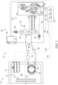
- FIG. 1 shows an illustrative arrangement of an electrical transformer 10 including a gas analysis system 12 for determining characteristics of dissolved gases within fluid of the transformer 10.
- the transformer 10 illustratively includes a housing 14 defining an interior 16 and electrical windings 18 arranged within the interior 16 of the housing 14.
- the electrical windings 18 illustratively comprise windings of electrical wiring forming a series of turns about limbs of the transformer 10 to produce electromagnetic effect when current is passed through the wiring.
- the transformer 10 is illustratively embodied as a high- voltage, three-phase, core type transformer, but in some embodiments, may include any manner of electromagnetic device including but not limited to shell type and/or single or multi-phase.
- the housing 14 contains fluid 20 for cooling and/or electrically insulating the components of the transformer 10, such as the electrical windings 18.
- dissolved gases can develop within the fluid 20 as a result of operable use of the fluid 20 for cooling and/or insulation (for example, by fluid breakdown and/or faulty operational issues of the transformer 10, generally, including leaks in the housing 14) and/or the fluid 20 may carry gases generated from the degradation of other insulation materials in the transformer, such as paper.
- the gas analysis system 12 is illustratively arranged to extract dissolved gases from the fluid 20 for analysis.
- the gas analysis system 12 includes an extraction probe 22 for extracting gas from the fluid 20.
- the extraction probe 22 is arranged in contact with the fluid 20 and is formed of a gas-permeable material to permit permeation of dissolved gases from the fluid 20.
- the extraction probe 22 is illustratively embodied as a conduit defining an interior passage for receiving and communicating gas.
- the gas-permeable material illustratively permits dissolved gases to permeate into the interior passage while inhibiting ingress of liquids, for example, dielectric oils. Suitable gas-permeable materials may include one or more fluoropolymers.
- the extraction probe 22 is formed as an extraction coil having coil loops in contact with the fluid 20. In other examples not forming part of the claimed invention, the extraction probe 22 may include any suitable shapes and/or forms.
- the gas analysis system 12 includes a gas analysis module 24 for conducting analysis of gas.
- the gas analysis module 24 is fluidly connected with the extraction probe 22 and forms a gas circuit for circulation of gas between the extraction probe 22 and the gas analysis module 24.
- An exemplary housing 25 of the gas analysis module 24 is shown in Figure 1 .
- the gas analysis module 24 illustratively includes a gas cell 26 for receiving gas extracted from the fluid 20.
- the gas cell 26 illustratively includes a cell body 28 defining a cavity 30 through which gas is passed for analysis.
- the gas analysis system 12 conducts optical analysis of gas to determine gas characteristics.
- portions of the gas circuit other than the extraction probe 22, including the cavity 30, are hermetically sealed to ambient air such that only the extraction probe 22 is arranged to allow permeation of gases into and out of the gas circuit, thereby allowing gas exchange with the transformer fluid 20.
- the gas analysis module 24 illustratively includes a gas analysis device 32 for conducting analysis of gas within the gas cell 26.
- the gas analysis device 32 is an optical device embodied as a light spectroscopy device, namely a Fourier transform infrared (FTIR) spectrometer.
- the gas analysis module 24 may perform any manner of gas analysis techniques and may include any suitable configuration and/or components to perform such techniques, for example, but without limitation, ultra violet light spectroscopy, Raman spectroscopy, photoacoustic spectroscopy, tunable diode laser absorption spectroscopy (TDLAS).
- the gas analysis device 32 illustratively performs light spectrum analysis of gas within the gas cell 26.
- the gas cell 26 may use optical path length enhancement techniques such as multi-pass cells or resonant cavities.
- Multi-pass cells may include White cell, Herriot cell, folded path cells, and/or other multi-pass cells.
- Resonant cavities may include Fabry-Perot cavities, cavities designed for cavity ring-down spectroscopy, integrated cavity output spectroscopy (ICOS), off-axis integrated cavity output spectroscopy (OA-ICOS), and/or other optical path length enhancement techniques.
- the gas analysis device 32 illustratively includes a light source 34 and detectors 36, 38 for receiving light from the light source 34.
- the light source 34 illustratively generates infrared (IR) light for propagation through gas for observation of the light absorption characteristics of the gas.
- the light directed through the gas is received by the detectors 36, 38.
- the detectors 36, 38 are illustratively embodied as photodetectors that receive light propagated through gas (but that has not been absorbed by the gas) and that generate an electrical signal indicating the light received.
- the detectors 36, 38 are illustratively embodied as analog detectors that generate an analog signal that is converted to a digital signal by an analog-to-digital converter.
- the detectors 36, 38 may include any suitable arrangement of signal generation for gas analysis.
- the gas analysis device 32 illustratively determines characteristics of the gas based on the light received by the detectors 36, 38.
- the gas analysis module 24 can determine characteristics of dissolved gas within the fluid 20 by analysis of gas extracted by the gas analysis system 12 from the transformer 10. Relevant characteristics of dissolved gases within the fluid 20 of the transformer 10 include the presence and/or identification of such gases and their dissolved concentrations within the fluid 20.
- a non- exhaustive list of gases of interest within the fluid 20 may include, for example, oxygen (O 2 ), nitrogen (N 2 ), hydrogen (H 2 ), carbon dioxide (CO 2 ), and/or hydrocarbons (e.g., methane, ethane, acetylene, and/or ethylene), among other gases.
- the gas analysis device 32 may also monitor water vapor (H 2 O) extracted from the moisture dissolved in transformer oil 20.
- the housing 14 of the transformer 10 illustratively includes a sampling portal 40 defining a portion of the interior 16 containing fluid 20 as part of the housing 14.
- the sampling portal 40 illustratively includes pipe extension 42 connected with a wall 43 of the transformer 10 and a shroud 44 secured with the pipe extension 42.
- the extraction probe 22 is illustratively mounted within the shroud 44 in contact with fluid 20.
- the extraction probe 22 is illustratively mounted within a fluid chamber 46 defined by the shroud 44 as a part of the interior 16.
- the chamber 46 illustratively contains fluid 20 as part of the housing 14 and fluidly communicating through the pipe extension 42.
- the pipe extension 42 illustratively includes a valve 48 disposed fluidly between the wall 43 and the chamber 46 to permit isolation of the extraction probe 22, but in some embodiments, the valve 48 may be excluded. In some embodiments, the extraction probe 22 may be arranged inside of the wall 43.
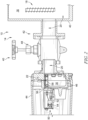
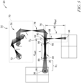
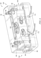
- the gas analysis system 12 includes an extraction module 50 as shown in Figures 2-4 ,
- the extraction module 50 provides a packaging platform for mounting the extraction probe 22 within the housing 14 as shown in Figure 2 .
- the extraction module 50 includes a mounting frame 52 and the extraction probe 22 secured with the mounting frame 52.
- a pump 54 is mounted to the frame 54 and is fluidly connected with the extraction probe 22 to provide a motive pressure source for circulation of gas within the gas circuit.
- Control valves and/or other flow distribution devices for operation of the gas circuit may be mounted to the mounting frame 52.
- the mounting frame 52 includes an engagement wall 56 and a probe arm 58 extending from the engagement wall 56.
- the engagement wall 56 illustratively includes a face 60 that forms at least a portion of fluid boundary of the chamber 46.
- the engagement wall 56 illustratively supports the probe arm 58 for extension within the chamber 46 for contact with fluid 20.
- the probe arm 58 includes a spool 62 having the extraction probe 22 (which according to the invention is an extraction coil) looped around the spool 62.
- the extraction coil is looped around the spool 62 to form a number of coil turns having a successively stacked arrangement for exposure to fluid 20. Increasing the number of coils may improve the effective exchange surface between oil and gas phase and may reduce the response time of the measurement.
- Gas circulated through the extraction probe 22 portion of the gas circuit illustratively flows successively through each of the coil turns and out for circulation to the gas analysis device 32.
- the extraction probe 22 is fluidly connected with the pump 54 for communication of extracted gas through the gas circuit.
- the spool 62 is illustratively cantilevered from the engagement wall 56 and provides structure for arranging the extraction probe 22 for contact with fluid 20.
- the extraction probe 22 may be secured to the mounting frame 52 in any suitable manner and/or arrangement.
- the spool 62 is illustratively formed as a structural frame defining an annular spool bed 61 for receiving the extraction probe 22 wrapped thereon and defining openings 63 extending through the spool bed 61 to permit fluid 20 to contact interior portions of the extraction probe 22 to increase the effective exchange surface between oil and gas phase.
- the spool 62 is illustratively shaped as a hollow cylinder to permit fluid 20 therein.
- the spool 62 illustratively includes a strut 65 bridging radially across the spool bed 61 to provide structural support and defining openings 67 to permit circulation of fluid 20 through the spool 62.
- the extraction probe 22 and the gas analysis module 24 are fluidly connected to define a gas circuit for circulation of gas therebetween.
- the extraction probe 22 and the gas analysis module 24 are fluidly connected by transport conduit 64 including conduit segments 66, 68.
- the segment 66 is illustratively embodied as a supply segment for providing gas from the extraction probe 22 to the gas analysis module 24 and the segment 68 is embodied as a return segment for providing gas from the gas analysis module 24 to the extraction probe 22.
- the pump 54 is arranged fluidly along the supply segment 66 and provides a lower pressure level at the output of the extraction probe 22 (relative to the pressure of the gas cell 26), which may assist with extraction of dissolved gases.
- the gas circuit may be formed substantially or entirely by the extraction probe 22 and gas analysis module 24 being fluidly connected with each other by direct connection and/or with little or no transport conduit 64.
- the extraction probe 22 and gas analysis module 24 may be partly or wholly combined into a common module and/or arranged within a common housing for compact arrangement.
- the gas circuit provides a circulation loop for communication of gas between the extraction probe 22 and the gas analysis module 24.
- the gas circuit encourages the gas extracted from the fluid 20 to reach and maintain equilibrium with dissolved gases within the fluid 20.
- passive extraction and non-destructive analysis can avoid practical challenges with active sampling, such as fluid leaks, contamination, and waste materials, among others. Passive extraction does not rely on a precise determination of the extraction rate of the gas and thus reduces the need for factory calibration of each analyzer extraction rate.
- the pump 54 illustratively assists circulation of the gas through the gas circuit and may assist extraction, but in some embodiments, circulation of the gas through the gas circuit may be provided by any suitable device(s), including but not limited to redundant pumps arrangements or arrangements without a pump such as convective and/or diffusive transport.
- the gas analysis module 24 illustratively includes the gas analysis device 32 arranged for conducting analysis of gas within the gas cell 26.
- the light source 34 of the gas analysis device 32 illustratively includes a light generation source 70.
- the light generation source 70 includes an interferometer for modulating mid-IR light, for example, with a wavelength within a range of about 1 microns to about 50 microns (in some illustrative embodiments), about 2.5 microns to about 25 microns (in other illustrative embodiments), and about 2.5 to about 16 microns (in still other illustrative embodiments).
- the light generation source 70 also illustratively includes at least one light generator 72 for generating the mid-IR light and may include various relays, filters, and/or other conditioning devices (collectively indicated as 74) for providing suitable light for gas analysis.
- a non-limiting example of a suitable light generator 72 may include a glow bar (globar).
- the light source 34 illustratively includes a relay mirror 76 arranged to receive a beam of light 78 from the light generation source 70 and a beam splitter 80 arranged to receive the beam 78 from the relay mirror 76.
- the gas analysis device 32 illustratively includes two optical channels as explained herein.
- the beam splitter 80 illustratively divides the beam 78 into two beams of light 82, 84 for spectrum analysis.
- the beam splitter 80 is illustratively embodied to have a beam- splitting ratio of 50:50 (50/50 splitter) dividing the beam 78 evenly into the two beams 82, 84, but in some embodiments, the beam splitter 80 may have other suitable beam-splitting ratios.
- any suitable arrangement of relays, filters, splitters, and/or other conditioning devices may be employed to propagate light accordingly for gas analysis. Beams 82, 84 propagate through respective defined spaces for collection by detectors 36, 38.
- analysis of the beams 82, 84 propagated through respective defined spaces can determine characteristics of the gas extracted from the fluid 20.
- the beam 82 illustratively propagates through the gas cell 26 for reception by detector 36.
- the beam 82 illustratively enters the gas cell 26 through a window 86, propagates through the cavity 30 for interaction with gas therein, and exits the gas cell 26 through another window 88.
- Light from the beam 82 exiting the gas cell 26 is received by the detector 36 for analysis.
- the gas within the cavity 30 affects the beam 82 in a manner such that the affected light received by detector 36 can indicate characteristics of the gas within the cavity 30.
- the detector 36 can generate a signal related to the absorption spectrum of the gas within the cavity 30 based on the light received from beam 82.
- the gas within the cavity 30 absorbs energy from the beam 82 in the form of electromagnetic radiation.
- the remaining energy of beam 82 passes through the gas and is received by the detector 36 to generate a signal related to an absorption spectrum in the illustrative embodiment.
- the absorption spectrum of the relevant gas can include the fraction of incident radiation absorbed by the gas sample (in this instance, the gas within the cavity 30) over a range of wavelengths and/or frequencies of propagated light.
- the characteristics of the gas within the cavity 30 can be reliably determined.
- characteristics of the dissolved gases within fluid 20 can be determined based on the characteristics of the gas within the cavity 30.
- additional gas analysis devices may be included in the gas cell to detect certain gases, such as hydrogen (H 2 ), oxygen (O 2 ), and/or nitrogen (N 2 ), and some of those additional gas analysis devices may use non-optical measurement principals that do not require gas interaction with light, such as resistive, capacitive, and/or thermo-conductive sensors, by way of example.
- Accurate determination of the characteristics of gas within the cavity 30 (and ultimately the dissolved gases within fluid 20) should account for contaminants and/or artifacts.
- Common sources of artifacts includes constituents within the air contained in the gas analysis module 24 and/or constituents within the air in the vicinity of the transformer 10 that may enter the gas analysis module 24.
- ambient air within the gas analysis module 24 can reduce the light received by the detector 36 even though it cannot enter into the cavity 30. Accordingly, reference information regarding the ambient environment can be useful in interpreting the light received by the detector 36.
- the terms "air” and "ambient air” are not intended to limit the gas constituents which can be considered, but may include any gas constituent, including constituents of the same species as the dissolved gases of interest in the fluid 20.
- the characteristics of the gas within the cavity 30 can be accurately determined by correction and/or calibration of the light received by the detector 36 (absorption spectrum).
- Such corrective approaches can reduce the need for purging, scrubbing, desiccants, relay adjustment, and/or other resource-laden or mechanically demanding techniques to achieve accurate results.
- the beam 84 (split from the beam 82) illustratively propagates through a reference space 90 to provide characteristics of ambient air as reference information.
- the reference space 90 illustratively contains ambient gas (illustratively embodied as ambient air) which affects the beam 84 in a manner such that the affected light received by detector 38 can indicate characteristics of the ambient gas.
- the characteristics of the ambient gas can be used in interpreting the light received by detector 36. Analysis of the light received by the detector 36 in combination with the light received by the detector 38 can allow determination of characteristics of the gas within the cavity 30 (and, hence, the characteristics of the dissolved gases within the fluid 20) by reducing artifacts from the light absorbed by the ambient gas. Reduction of artifacts from the light absorbed by the ambient gas is illustratively achieved by consideration of the corresponding absorption spectra perceived by detectors 36, 38.
- reference information may be obtained by any suitable technique and/or equipment.
- the beam splitter 80 effectively provides a reference source point 92 for propagation of light through the defined spaces 30, 90.
- the reference source point 92 is illustratively represented as a single point on the beam splitter 80 for descriptive purposes.
- a propagation distance d i is illustratively defined between the reference source point 92 and each of the detectors 36, 38.
- a first propagation distance, referred to as a cell distance d cell is illustratively defined between the reference source point 92 and the detector 36.
- the cell distance d cell illustratively corresponds to the propagation of the beam 82.
- a second propagation distance referred to as a reference distance d Ref is illustratively defined between the reference source point 92 and the detector 38.
- the reference distance d Ref illustratively corresponds to the propagation of the beam 84.
- a third propagation distance referred to as the cell body distance L , is illustratively defined between the first window 86 and the second window 88 delimiting the cavity 30 of the gas cell 26.
- the distance (span) resulting from the subtraction of the cell body distance L from the cell distance d cell (e.g., the span may include the sum of the distance between the reference source point 92 and the cavity 30, S 1 , and the distance between the detector 36 and the cavity 30, S 2 , as indicated in Fig. 5 , either or both of which may contain ambient gas) is substantially equal to the reference distance d Ref in such a way that the propagation distances in ambient air between the reference source point 92 and each of the detectors 36, 38 are substantially equal. In other embodiments, however, the propagation distances in ambient air between the reference source point 92 and each of the detectors 36, 38 may be different from each other and a correlation can be applied to equate their corresponding absorption spectra.
- the cell distance d cell may be substantially equal to the sum of the reference distance d Ref and the cell body distance L .
- the propagation distances between the reference source point 92 and each of the detectors 36, 38 may be substantially equal. In some embodiments, the propagation distances may be different from each other and a correlation can be applied to equate their corresponding absorption spectra.
- the light source 34 provides the beam of light 78 for division into beams 82, 84 for respective propagation through each of the cavity 30 and reference space 90.
- the light source 34 illustratively provides each of beams 82, 84 simultaneously from the same source for use in two optical channels; one channel analyzing light propagated through the gas cell 26, and another channel analyzing light propagated through the reference space 90.
- the dual channel arrangement using the same source of light can promote uniformity between the spectral characteristics of the channels and decrease adjustable parameters (e.g., moving optics, pressure/temperature modulation of gas samples) and/or the use of commodities (e.g., purge gas, desiccants, scrubbers) in obtaining reliable readings.
- Devices, systems, and methods of the present disclosure can be advantageous for remote operation where commodities and/or maintenance availability is of concern. Moreover, arrangements of the present disclosure can account for unexpected and/or unknown contaminants, even without identifying the exact contaminant.
- the reference information of the ambient gas may not identify one or more of the substances in the gas analysis module 24 and/or located between the light generator 72 and detectors 36, 38. However, the reference information of the unidentified substance can still be considered in accurately determining the characteristics of the gas within the cavity 30.
- the gas cell 26 illustratively includes a housing 94, which is shown partially cutaway (and semi- transparent) to reveal a cell body 96 that defines the cavity 30 therein (the cell body 96 being an illustrative embodiment of the cell body 28 of Figure 1 ).
- the cell body 96 illustratively includes openings 98 penetrating through the cell body 96 on opposite ends 100, 102 to connect with the cavity 30. Each opening 98 is enclosed by a respective one of the windows 86, 88.
- the cell body 96 illustratively includes gas ports 104, 106 that each penetrate through the housing 94 and fluidly connect with the cavity 30 to form a portion of the gas circuit to communicate gas with the extraction probe 22.
- the gas port 104 is illustratively embodied as an inlet port (relative to the gas cell 26) for receiving gas from the extraction probe 22 and the gas port 106 is embodied as an outlet port for sending gas to the extraction probe 22.
- the cell body 96 illustratively includes pressure and temperature sensor ports 108 for insertion of pressure and temperature sensors 122, 124 (shown in Figure 1 ) to monitor the conditions within the cavity 30.
- a cell heater 110 including electrical leads 111 is illustratively connected with the cell body 96 within the housing 94 to provide temperature control of the cavity 30.
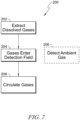
- FIG. 7 an illustrative flow diagram is shown.
- a process 200 for determining characteristics of gases is described relative to boxes 202-208.
- box 202 dissolved gases are illustratively extracted from fluid 20 of the transformer 10.
- the dissolved gases are extracted by permeation into the extraction probe 22 to enter the gas circuit.
- the process illustratively proceeds from box 202 to box 204.
- extracted gas illustratively enters a detection field.
- the extracted gas enters the detection field as it circulates through the gas cell 26 and light is propagated through the extracted gas for reception by the detector 36.
- the characteristics of ambient gases are detected.
- the second channel of the gas analysis module 24 propagates light through the reference space 90 and the ambient gas therein for reception by the detector 38. The process proceeds from box 204 to box 208.
- gas within the detection field circulates out of the detection field.
- gas within the gas cell 26 is circulated through the gas circuit to return to the extraction probe 22.
- the circulation of the gas within the gas circuit promotes nondestructive testing and enables equilibrium between gas in the gas circuit and dissolved gas within the fluid 20.
- the control system 112 illustratively includes a processor 114, memory device 116, and communications circuitry 118 in communication with each other.
- the memory device 116 stores instructions for execution by the processor 114 to conduct operations of the gas analysis system 12.
- the instructions include at least one algorithm for conducting the disclosed operations, but in some embodiments, the instructions may include any of look up tables, charts, and/or other reference material.
- the communications circuitry 118 illustratively includes various circuitry arranged to send and receive communication signals between the control system 112 and various components as directed by the processor 114.
- the communications circuitry 118 also allows the control system 112 to communicate with other devices, including remote devices, and along various communications networks, such that the gas analysis system 12 (as well as the transformer 10) can be connected to and form part of the Internet of Things. As a result, various components of the gas analysis system 12 may be sensed and/or controlled remotely across existing network infrastructure.
- the control system 112 is illustratively arranged in communication with the gas analysis module 24 and the pump 54 through communication links 120 to communicate signals to govern their operation.
- Communication links 120 illustratively include hardwired connections, but in some embodiments may include any of hardwired and wireless connections, and/or combinations thereof.
- the control system 112 is in communication with each of the light source 34, the detectors 36, 38, gas cell temperature and pressure sensors 122, 124 through individual links 120, but in some embodiments, the control system 112 may be in communication with components of the gas analysis module 24 by one or more shared links 120.
- the control system 112 illustratively performs spectrum analysis of the light received by the detectors 36, 38 and determines the characteristics of the gas within the cavity 30 and the corresponding characteristics of the dissolved gas within the fluid 20.
- the transformer 10 illustratively includes a pump 126 arranged to circulate fluid 20 within the housing 14. Circulating the fluid 20 can assist in providing uniform distribution of dissolved gases and can assist in extracted gases reaching accurate equilibrium faster than with stagnant fluid conditions.
- the pump 126 is a thermal pump circulating the fluid 20 by convective movement.
- any suitable device for circulating the fluid 20 may be used, including, for example, a displacement pump and/or an agitator.
- the control system 112 is in communication with the pump 126 to govern operation of the pump 126.
- control system 112 is embodied to govern operations of all components of the gas analysis system 12. In some embodiments, the control system 112 may govern operation of other systems of the transformer 10. In some embodiments, the control system 112 may include multiple processors, memory devices, and/or communications circuitry that may have any suitable arrangement including but not limited to dedicated and partly or wholly shared arrangements. In some embodiments, another control system 112 may be dedicated to govern operation of the gas analysis module 24 and the remainder of the gas analysis system 12 may be governed by the control system 112.
- the extraction probe 22 may include a suitable permeable material, for example, fluoropolymers.
- suitable gas-permeable materials may include, for example, but without limitation, amorphous fluoroplastics. such as Teflon ® AF and/or Chemours ® AF, as marketed by Professional Plastics, Inc.
- Non-limiting examples may include Teflon ® AF 1600 and/or Teflon ® AF 2400 (and/or Chemours ® AF 1600 and/or AF 2400) having typical properties as described within the table below:
- any suitable materials for gas-permeable, liquid-resistant extraction of dissolved gases from transformer fluid may be applied.
- the present disclosure includes devices, systems, and methods for oil and gas management for dissolved gas analyzers for use in transformer monitoring.
- the devices, systems, and methods of the present disclosure may include detecting dissolved gases in insulating oil of electrical equipment using gas equilibrium theory. Equilibrium can be achieved relative to the solubility of a gas in a transformer fluid 20, such as mineral oils, ester-based oils, or other insulation fluids, at a given temperature and for a given partial vapor pressure of a gas.
- Gas solubility can be described with quantities such as Ostwald coefficients of gas solubility that are specific to the type of fluid and to each gas constituent and may have temperature dependency. Gas solubility coefficients can be used to relate the partial pressure of gas in the gas cell with the concentration of dissolved gas in oil.
- the extraction probe 22 of the present disclosure may comprise at least one ring of highly gas permeable tubing that is not permeable to liquid.
- the extraction probe 22 may be connected to a closed-circulation system.
- the closed-circulation system may include one or more pumps for gas circulation and a gas cell, for example, gas cell 26, for analytical measurement of the gas.
- the present disclosure includes devices, systems, and methods adapted to monitor the health of a transformer by measuring dissolved gases within insulating oil of the transformer. For example, the concentration of specific gases can give indications of specific aspects of the operation of the transformer.
- Direct oil sampling and analysis of dissolved gases contained in transformer oil use active extraction of the gases and active measurement technics that consume the gases through the analyses. They are often implemented by circulating and/or conditioning oil samples outside the transformer in an oil circuit and may present a risk of oil leakage in case of breakage of the oil circuit.
- embodiments of the devices, systems, and methods of the present disclosure permit online measurement with high accuracy and without active extraction.
- oil containing the dissolved gases is circulating around highly permeable material tube within a fluid chamber 46 communicating fluidly with the transformer 10 through the pipe extension 42.
- the oil circulation around the permeable tube may be generated by pump, propeller and/or other mechanical systems and/or using thermally induced convection. Gases contained in oil can pass through permeable material to reach the gas phase loop. The permeable material properties can assist in obtaining equilibrium between gases in the liquid and gases in the gas phase loop.
- the gas loop may include a gas cell with optical inlet and outlet allowing examination of the gases by optical analyzer.
- Devices, systems, and methods of the present disclosure may include highly permeable fluoropolymer tubing, such as Teflon AF family of amorphous fluoroplastics, by way of example. Highly gas permeable material can promote gas equilibrium and can improve measurement response time.
- the tubing may be rolled to form one or more turns of a coil.
- Devices, systems, and methods of the present disclosure may include circulation of the transformer fluid (e.g., oil) around this coil.
- a structural ring may support the tubing.
- the fluoropolymer tubing may be connected to a gas circulating loop.
- the gas circulating loop may include one or more pumps to enhance reliability.
- stainless steel tubing may transport gas to a gas cell for analysis.
- a spectrometer may perform analysis of the gases.
- in-oil sensors may be used for H 2 and/or H 2 O measurement.
- Devices, systems, and methods of the present disclosure may include passive extraction of dissolved gases and measurement, in lieu of active principles for gas separation and measurement.
- the present disclosure may include transport of extracted gases without a carrier medium (e.g., a carrier gas).
- a lower pressure may be formed within the extraction probe 22, relative to the pressure within the gas cell 26 to assist with extraction of dissolved gases.
- Devices, systems, and methods of the present disclosure can be used in transformer monitoring and/or specifically in monitoring of dissolved gases analysis in transformer fluid such as oil.
- gases can be extracted from the transformer oil. Measurement of the gases can require a complex system for analysis, and in some embodiments, the gas sample can be transported to a gas analyzer.
- the devices, systems, and methods of the present disclosure can be helpful in avoiding transporting the transformer oil itself to an analyzer, which can present a risk of oil leakage in case of tubing breakage.
- Use of passive measurement and passive extraction of the gases can simplify the calibration and installation of gas analysis systems.
- Use of high porosity and/or highly permeability material can help to reach equilibrium between gases in oil and gases in the sample gas phase. Using gases equilibrium, without requiring new gases to be sampled, can reduce risk of contamination of the oil.
- Use of a lower pressure (relative to the pressure within the gas cell) in the gas sampling probe can reduce the response time of the systems.
- the use of multiple transport pumps can help to reduce risk of failure.
- measurement of H 2 may be conducted in gas phase to reduce the cost.
- measurement of O 2 , H 2 , and/or N 2 may be performed optically and/or with non-optical sensors.
- O 2 can be measured by paramagnetic analyzer.
- gas leak detection may be performed by monitoring the presence of CO 2 or H 2 O with the gas cell, whether by direct and/or indirect sampling.
- the present disclosed devices, systems, and methods may involve advanced analyses and identification of interferent and outlier.
- the present disclosure includes devices, systems, and methods for dual channel optical gas analyzers for compensation of ambient air constituents.
- Spectrometers can be used to measure light absorption spectra of gases.
- gases of interest in a sample under observation are also present in ambient air (e.g., air either in the analyzer and/or around the sampling system) or when other gases in ambient air might interfere with the measurement of the gases of interest, spectrometers often must be purged, for example, with a purified gas to determine the contribution due to the absorption of only the gases of interest in the gas sample.
- the present disclosure includes devices, systems, and methods to reduce and/or remove the need for conditioning of the air in the analyzer or around the sampling system.
- the present disclosure includes spectrometers with two measurement channels.
- One channel can receive light propagating through ambient air and through a sampling gas cell. The transmitted light is then detected by a photodetector which generates an electrical signal that is digitized using an analog to digital converter. Another channel receives light propagating through ambient air only. Unlike in the first channel, the light of this second channel is not propagating through the sampling gas cell. The gas absorption contribution to the transmitted light in this second channel is related to ambient air constituents. The transmitted light of this second channel is detected by a second photodetector which generates an electrical signal that is digitized using a second analog to digital converter.
- Devices, systems, and methods within the present disclosure may include light sources that split the light (e.g., by beam splitter, light divider, and/or any other suitable light splitting technique), a gas cell that may contain one or many gases of interest, components to insert gases into the gas cell, a first detector measuring the light transmitted through the gas cell and through ambient air, a second detector measuring the light transmitted only through ambient air, a processor to determine the concentration of one or more gases present in the sampling gas cell from the first channel signal, and remove interferences and/or contribution of gases in ambient air of the first channel based on the ambient air signal recorded from the second channel.
- light sources that split the light (e.g., by beam splitter, light divider, and/or any other suitable light splitting technique)
- a gas cell that may contain one or many gases of interest, components to insert gases into the gas cell
- a first detector measuring the light transmitted through the gas cell and through ambient air
- a second detector measuring the light transmitted only through ambient air
- a processor to determine the concentration of one or more gases
- a light source may be modulated by an interferometer.
- the light source may be divided in two different beams by a 50/50 Wedged ZnSe Beamsplitter.
- One of the beams may propagate through the gas cell and may reach the gas cell detector.
- the other beam may be directed towards a reference detector, to sense the ambient air composition only.
- the propagation distance in ambient air can be adjusted for both beams. The adjustment can be performed in a manner such that both the light transmitted by the gas cell and reaching the first detector and the light reaching the reference detector of the second channel propagate through similar distances in ambient air.
- it may be assumed that ambient air composition in the instrument is homogeneous, and the light absorption due to the gases from ambient air should be the proportional to the gases concentration as well as to the respective propagation distance of both channels.
- the gas cell may be a closed container with one inlet and one outlet to fluidly connect to form a gas circulation loop.
- the light from the interferometer can enter the gas cell from one side and exit through the other side to the gas cell detector.
- the gas cell can be temperature controlled by a cartridge heater. The pressure and temperature of the gases in the gas cell can be measured and used as input parameters to the calculation of gases concentrations.
- the present disclosure includes devices, systems, and methods in which the need for a purging system can be reduced and/or removed. Reducing and/or removing the need for a purging system can be an advantage when an analyzer is located in remote areas and purging systems are not available and/or are costly to install and operate. Concentration of gases in the gas cell that may also be present ambient air can be determined without purge, scrubber, desiccant and/or analyzer sealing. Other ambient air gases which have absorption signatures that may interfere with the determination of the gases concentration in the gas cell may also be compensated without purge, scrubber, desiccant and/or sealing.
- the gases in ambient air can be measured simultaneously with the gases in the gas cell if desired, as opposed to calibration methods where only one channel can be used.
- Single channel calibration may perform reference background measurement taken apart from and/or without the gases of interest in the gas cell.
- the devices, systems, and methods of the present disclosure can provide an advantage when ambient air composition varies over time.
- the devices, systems, and methods of the present disclosure can include calibration for spectral intensity of the source, and calibration for the spectral characteristics of optical components that are common to both the first and second channels.
- the present disclosure is used in the field of transformer monitoring by analysis of dissolved gases.
- the teachings of the present disclosure are generally applicable to other fields where optical methods require purge, scrubber, desiccant and/or sealing in order to calibrate, remove, and/or correct for ambient air constituents, but this does not form part of the claimed invention.
- the devices, systems, and methods of the present disclosure can provide an alternative to systems taking reference measurements using only one detector, by removing the gases of interests from the gas cell and/or bypassing the gas cell.
- Measuring low concentration gases by spectroscopy with accuracy can be challenging, particularly when the same gases or other interfering gases are present in ambient air, either in the analyzer or around the sampling system. Concentration of these gases in ambient air and/or the relative propagation distance of the light in ambient air could be non- negligible compared to the concentration of the gases in the gas cell and the propagation distance in the gas cell. Furthermore, the concentration of these gases in ambient air may vary with time, and unexpected gases can appear in ambient air in some sites. Pressure and temperature of the ambient air may differ from the pressure and temperature of the gas sample in the gas cell.
- analyzers are often purged with purified gases (by way of example, the MB3000 spectrometer marketed by ABB Inc., includes a purging option). Purging can require bottles of purified gases, like Nitrogen, and/or a purified gas generator. Purge air is often dried to remove humidity, which can be a significant interferent in some instances, and CO 2 is often removed as well with a scrubber. In other systems where a purge is not possible and/or desirable, desiccants and/or scrubbers are used to remove humidity and/or other gases, but must be replaced or regenerated after some time.
- Other exemplary techniques can include moving relay mirrors to the gas cell in and out of the first channel in order to bypass the gas cell and direct the light to the detector to take background measurement.
- the relay optics can be designed such that the propagating distance in air with and without the relay optics is the same.
- Still other exemplary techniques can include using a scrubber to remove the gas component of interest from the gas cell after measuring the gas sample with the gas component of interest and inferring its concentration by the comparison of those two alternate measurements.
- Still other techniques may vary the pressure and/or the temperature of the gas sample to discriminate its composition over ambient air composition.
- the purge gas is supplied from an exhaustible source, such as a bottle, the exhaustible source will need to be refilled and/or changed at periodic maintenance intervals.
- Purge generators can be costly equipment that can require maintenance as well. Scrubbers and desiccants also require maintenance. Thus, the purge-based systems can increase the cost of operating spectrometers.
- the present disclosure can include reducing and/or removing the need for a purging system, desiccants, scrubbers and/or instrument sealing. Accordingly, the devices, systems, and methods of the present disclosure can reduce installation and/or maintenance costs related to the spectrometer, and can enable solutions for remote sites where purging systems are not available and/or maintenance cannot be performed frequently due to cost and/or safety issues. In some embodiments, the devices, systems, and methods of the present disclosure do not require moving optics and/or sample gas pressure modulation, and the ambient air constituents can be measured simultaneously with the gas cell constituents.
- spectrometers using certain teachings of the present disclosure can measure spectra of ambient air, they may also detect and/or compensate for unexpected gases present in the ambient air, as opposed to scrubbers that are designed for specific constituents.
- Devices, systems, and methods of the present disclosure may be used to detect other defects around the transformer, for example but without limitation, detection of insulation gas leaks, such as SF 6 .
- the devices, systems, and methods of the present disclosure can reduce sensitivity to ambient air compositions.
- the composition of the air inside the optical analyzer and/or around the sampling system may not need to be controlled by use of purge system, desiccants, scrubbers and/or instrument sealing.
- the devices, systems, and methods of the present disclosure may use factory calibration to characterize the difference of light propagating distances in air between first and second channels.
- the devices, systems, and methods of the present disclosure may use factory calibration of the system to measure the spectral response of the first and second detectors as well as spectral response of optical components not common to first and second channel.
- the devices, systems, and methods of the present disclosure may use factory calibration to characterize the spectral response and/or instrument line shape of the first and second channels in order to improve the compensation of air constituents in the first channel using the second channel.
- Factory calibration may include purge of the analyzer.
- the present disclosure include techniques developed to adjust the position of system components (mirrors, lenses, detectors, etc.) to minimize the difference of light propagating distance in air between first and second channel.
- one or more algorithms may be used to compensate for the ambient constituents of the first channel using the second channel signal.
Landscapes
- Life Sciences & Earth Sciences (AREA)
- Health & Medical Sciences (AREA)
- Physics & Mathematics (AREA)
- Engineering & Computer Science (AREA)
- Chemical & Material Sciences (AREA)
- General Physics & Mathematics (AREA)
- Analytical Chemistry (AREA)
- Biochemistry (AREA)
- General Health & Medical Sciences (AREA)
- Immunology (AREA)
- Pathology (AREA)
- Power Engineering (AREA)
- Biomedical Technology (AREA)
- Spectroscopy & Molecular Physics (AREA)
- Molecular Biology (AREA)
- Chemical Kinetics & Catalysis (AREA)
- Oil, Petroleum & Natural Gas (AREA)
- Food Science & Technology (AREA)
- Medicinal Chemistry (AREA)
- General Chemical & Material Sciences (AREA)
- Investigating Or Analysing Materials By Optical Means (AREA)
- Sampling And Sample Adjustment (AREA)
- Investigating, Analyzing Materials By Fluorescence Or Luminescence (AREA)
Priority Applications (1)
| Application Number | Priority Date | Filing Date | Title |
|---|---|---|---|
| EP24223886.3A EP4513169A3 (en) | 2017-03-13 | 2018-03-13 | Dissolved gas analysis devices, systems, and methods |
Applications Claiming Priority (3)
| Application Number | Priority Date | Filing Date | Title |
|---|---|---|---|
| US15/458,014 US10585036B2 (en) | 2017-03-13 | 2017-03-13 | Dissolved gas analysis devices, systems, and methods |
| US15/458,010 US10586649B2 (en) | 2017-03-13 | 2017-03-13 | Dissolved gas analysis devices, systems, and methods |
| PCT/CA2018/050298 WO2018165749A1 (en) | 2017-03-13 | 2018-03-13 | Dissolved gas analysis devices, systems, and methods |
Related Child Applications (1)
| Application Number | Title | Priority Date | Filing Date |
|---|---|---|---|
| EP24223886.3A Division EP4513169A3 (en) | 2017-03-13 | 2018-03-13 | Dissolved gas analysis devices, systems, and methods |
Publications (3)
| Publication Number | Publication Date |
|---|---|
| EP3596443A1 EP3596443A1 (en) | 2020-01-22 |
| EP3596443A4 EP3596443A4 (en) | 2020-12-23 |
| EP3596443B1 true EP3596443B1 (en) | 2025-01-01 |
Family
ID=63521684
Family Applications (2)
| Application Number | Title | Priority Date | Filing Date |
|---|---|---|---|
| EP18767035.1A Active EP3596443B1 (en) | 2017-03-13 | 2018-03-13 | Dissolved gas analysis devices, systems, and methods |
| EP24223886.3A Pending EP4513169A3 (en) | 2017-03-13 | 2018-03-13 | Dissolved gas analysis devices, systems, and methods |
Family Applications After (1)
| Application Number | Title | Priority Date | Filing Date |
|---|---|---|---|
| EP24223886.3A Pending EP4513169A3 (en) | 2017-03-13 | 2018-03-13 | Dissolved gas analysis devices, systems, and methods |
Country Status (5)
| Country | Link |
|---|---|
| EP (2) | EP3596443B1 (pl) |
| CN (2) | CN110770568B (pl) |
| ES (1) | ES3014025T3 (pl) |
| PL (1) | PL3596443T3 (pl) |
| WO (1) | WO2018165749A1 (pl) |
Families Citing this family (3)
| Publication number | Priority date | Publication date | Assignee | Title |
|---|---|---|---|---|
| CN112414949B (zh) * | 2020-10-29 | 2025-03-18 | 国网山西省电力公司电力科学研究院 | 一种实时检测变压器故障的气体继电器及诊断方法 |
| CN112418451A (zh) * | 2020-11-05 | 2021-02-26 | 武汉大学 | 基于数字孪生的变压器故障诊断定位系统 |
| CN118533780B (zh) * | 2024-07-29 | 2024-09-17 | 成都铭鉴知源油田工程科技有限公司 | 一种基于紫外吸收法的检测硫化氢浓度的检测装置及方法 |
Citations (1)
| Publication number | Priority date | Publication date | Assignee | Title |
|---|---|---|---|---|
| JPS57156536A (en) * | 1981-03-20 | 1982-09-27 | Junkosha Co Ltd | Detector for gaseous hydrogen in oil |
Family Cites Families (21)
| Publication number | Priority date | Publication date | Assignee | Title |
|---|---|---|---|---|
| US4112737A (en) * | 1977-04-27 | 1978-09-12 | Morgan Schaffer Corporation | Transformer fault detection |
| CA1332204C (en) * | 1987-10-26 | 1994-10-04 | Kenneth W. Busch | Infrared emission detection |
| FR2733319B1 (fr) * | 1995-04-21 | 1997-05-23 | Air Liquide | Procede et dispositif d'analyse de traces d'impuretes dans un echantillon de gaz au moyen d'une diode laser |
| JPH09288058A (ja) * | 1996-04-22 | 1997-11-04 | Hitachi Cable Ltd | 油中ガス検出装置 |
| US5811812A (en) * | 1996-11-01 | 1998-09-22 | Andros, Incorporated | Multiple-gas NDIR analyzer |
| US6037592A (en) * | 1997-02-14 | 2000-03-14 | Underground Systems, Inc. | System for measuring gases dissolved in a liquid |
| US6391096B1 (en) * | 2000-06-09 | 2002-05-21 | Serveron Corporation | Apparatus and method for extracting and analyzing gas |
| US6526805B1 (en) * | 2000-08-11 | 2003-03-04 | General Electric Co. | Apparatus for continuously determining volatile substances dissolved in insulating fluid |
| EP1386140A1 (en) * | 2001-05-04 | 2004-02-04 | Sensors for Medicine and Science, Inc. | Electro-optical sensing device with reference channel |
| WO2008011140A2 (en) * | 2006-07-19 | 2008-01-24 | Viaspace, Inc. | Humidity sensor for fuel cells and combustion exhaust streams |
| US7499169B2 (en) * | 2006-07-19 | 2009-03-03 | Viaspace Inc. | Fuel cell and product of combustion humidity sensor |
| US8014965B2 (en) * | 2007-02-21 | 2011-09-06 | ABB Bomen | Spectral estimation of spectrometers time-sampled signals using fast implementation of the reverse non-uniform discrete fourier transform |
| US8075675B2 (en) * | 2008-06-12 | 2011-12-13 | Serveron Corporation | Apparatus and method for extracting gas from liquid |
| KR101715094B1 (ko) * | 2011-07-01 | 2017-03-13 | 현대중공업 주식회사 | 변압기 유중가스 분석장치 |
| CN202404070U (zh) * | 2011-12-30 | 2012-08-29 | 昆山和智电气设备有限公司 | 在线监测变压器油中气体含量的系统 |
| WO2013116799A1 (en) * | 2012-02-01 | 2013-08-08 | Lumasense Technologies Holding, Inc. | System and method for monitoring asset health by dissolved gas measurement |
| US20150099274A1 (en) * | 2012-06-17 | 2015-04-09 | Physical Logic Ag | Method and system for use in monitoring biological material |
| US9759610B2 (en) * | 2012-08-01 | 2017-09-12 | General Electric Company | Method and device for dissolved gas analysis |
| EP2746747A1 (en) * | 2012-12-21 | 2014-06-25 | ABB Research Ltd. | Sensor assembly and method for determining the hydrogen and moisture content of transformer oil |
| DE102013112823B3 (de) * | 2013-11-20 | 2015-03-26 | Maschinenfabrik Reinhausen Gmbh | Vorrichtung und Verfahren zur Detektion von Gas |
| US20160282313A1 (en) * | 2015-03-26 | 2016-09-29 | General Electric Company | Trace Gas Measurement Apparatus for Electrical Equipment |
-
2018
- 2018-03-13 PL PL18767035.1T patent/PL3596443T3/pl unknown
- 2018-03-13 CN CN201880028244.7A patent/CN110770568B/zh active Active
- 2018-03-13 WO PCT/CA2018/050298 patent/WO2018165749A1/en not_active Ceased
- 2018-03-13 EP EP18767035.1A patent/EP3596443B1/en active Active
- 2018-03-13 CN CN202310303289.3A patent/CN116296625A/zh active Pending
- 2018-03-13 ES ES18767035T patent/ES3014025T3/es active Active
- 2018-03-13 EP EP24223886.3A patent/EP4513169A3/en active Pending
Patent Citations (1)
| Publication number | Priority date | Publication date | Assignee | Title |
|---|---|---|---|---|
| JPS57156536A (en) * | 1981-03-20 | 1982-09-27 | Junkosha Co Ltd | Detector for gaseous hydrogen in oil |
Also Published As
| Publication number | Publication date |
|---|---|
| EP3596443A4 (en) | 2020-12-23 |
| CN110770568A (zh) | 2020-02-07 |
| EP4513169A2 (en) | 2025-02-26 |
| PL3596443T3 (pl) | 2025-05-12 |
| WO2018165749A1 (en) | 2018-09-20 |
| CN116296625A (zh) | 2023-06-23 |
| EP4513169A3 (en) | 2025-05-21 |
| CN110770568B (zh) | 2023-04-04 |
| ES3014025T3 (en) | 2025-04-16 |
| EP3596443A1 (en) | 2020-01-22 |
Similar Documents
| Publication | Publication Date | Title |
|---|---|---|
| US11860148B2 (en) | Dissolved gas analysis devices, systems, and methods | |
| US11796455B2 (en) | Dissolved gas analysis devices, systems, and methods | |
| US11137382B2 (en) | Apparatus and method for performing gas analysis using optical absorption spectroscopy, such as infrared (IR) and/or UV, and use thereof in apparatus and method for performing dissolved gas analysis (DGA) on a piece of electrical equipment | |
| US8154714B2 (en) | Gas analyzer | |
| US8125626B2 (en) | Hybrid gas analyzer | |
| Yin et al. | Highly sensitive SO2 photoacoustic sensor for SF6 decomposition detection using a compact mW-level diode-pumped solid-state laser emitting at 303 nm | |
| Li et al. | Multi-pass absorption enhanced photoacoustic spectrometer based on combined light sources for dissolved gas analysis in oil | |
| EP3596443B1 (en) | Dissolved gas analysis devices, systems, and methods | |
| US5604298A (en) | Gas measurement system | |
| US10365209B1 (en) | Apparatus and method for performing dissolved gas analysis on a piece of electrical equipment using resonant photo-acoustic spectroscopy and use thereof | |
| US11280724B2 (en) | Apparatus and method for performing calibration of a dissolved gas analysis system using optical absorption spectroscopy and use thereof in an apparatus and method for performing dissolved gas analysis (DGA) on a piece of electrical equipment | |
| US9846148B2 (en) | Method and device for dissolved gas analysis | |
| Hashiguchi et al. | Wavelength-meter controlled cavity ring-down spectroscopy: high-sensitivity detection of trace moisture in N2 at sub-ppb levels | |
| US9285308B2 (en) | Interference-compensating NDIR gas sensor for measuring acetylene | |
| AU2008363810A1 (en) | Gas analyzer | |
| EP3312589A1 (en) | Optical analyzing device and method for determining a parameter of a gas arranged inside a gas-insulated electrical apparatus | |
| JP2004279339A (ja) | 濃度測定装置 | |
| Shi et al. | Rapid online detection of dissolved acetylene in transformer oil by photoacoustic spectroscopy and membrane degassing | |
| Frish et al. | Field-rugged sensitive hydrogen peroxide sensor based on tunable diode laser absorption spectroscopy (TDLAS) | |
| Khadzhiyskaya et al. | TDLAS technology in the design of a device for assessing the humidity of natural gas | |
| KR100254935B1 (ko) | 근적외선 단파장 광원을 이용한 수분분석방법과 그 장치 |
Legal Events
| Date | Code | Title | Description |
|---|---|---|---|
| STAA | Information on the status of an ep patent application or granted ep patent |
Free format text: STATUS: THE INTERNATIONAL PUBLICATION HAS BEEN MADE |
|
| PUAI | Public reference made under article 153(3) epc to a published international application that has entered the european phase |
Free format text: ORIGINAL CODE: 0009012 |
|
| STAA | Information on the status of an ep patent application or granted ep patent |
Free format text: STATUS: REQUEST FOR EXAMINATION WAS MADE |
|
| 17P | Request for examination filed |
Effective date: 20191010 |
|
| AK | Designated contracting states |
Kind code of ref document: A1 Designated state(s): AL AT BE BG CH CY CZ DE DK EE ES FI FR GB GR HR HU IE IS IT LI LT LU LV MC MK MT NL NO PL PT RO RS SE SI SK SM TR |
|
| AX | Request for extension of the european patent |
Extension state: BA ME |
|
| DAV | Request for validation of the european patent (deleted) | ||
| DAX | Request for extension of the european patent (deleted) | ||
| A4 | Supplementary search report drawn up and despatched |
Effective date: 20201125 |
|
| RIC1 | Information provided on ipc code assigned before grant |
Ipc: G01N 33/28 20060101ALI20201119BHEP Ipc: G01N 1/24 20060101ALI20201119BHEP Ipc: H01F 27/12 20060101ALN20201119BHEP Ipc: G01N 21/39 20060101ALN20201119BHEP Ipc: G01N 21/35 20140101ALN20201119BHEP Ipc: G01N 21/65 20060101ALN20201119BHEP Ipc: G01N 21/17 20060101ALN20201119BHEP Ipc: G01N 1/22 20060101AFI20201119BHEP Ipc: G01N 1/26 20060101ALI20201119BHEP Ipc: G01N 21/03 20060101ALN20201119BHEP Ipc: G01N 21/11 20060101ALI20201119BHEP Ipc: G01N 21/3504 20140101ALI20201119BHEP Ipc: G01N 21/25 20060101ALI20201119BHEP Ipc: G01N 21/33 20060101ALN20201119BHEP |
|
| RAP3 | Party data changed (applicant data changed or rights of an application transferred) |
Owner name: ABB SCHWEIZ AG |
|
| RIN1 | Information on inventor provided before grant (corrected) |
Inventor name: BUIJS, HENRY L. Inventor name: BIBEAU, LOUIS-PHILIPPE A. Inventor name: OUELLET-BERLANGER, ALEX Inventor name: DESBIENS, RAPHAEL N. |
|
| STAA | Information on the status of an ep patent application or granted ep patent |
Free format text: STATUS: EXAMINATION IS IN PROGRESS |
|
| 17Q | First examination report despatched |
Effective date: 20220907 |
|
| GRAP | Despatch of communication of intention to grant a patent |
Free format text: ORIGINAL CODE: EPIDOSNIGR1 |
|
| STAA | Information on the status of an ep patent application or granted ep patent |
Free format text: STATUS: GRANT OF PATENT IS INTENDED |
|
| RIC1 | Information provided on ipc code assigned before grant |
Ipc: H01F 27/12 20060101ALN20240708BHEP Ipc: G01N 21/39 20060101ALN20240708BHEP Ipc: G01N 21/35 20140101ALN20240708BHEP Ipc: G01N 21/17 20060101ALN20240708BHEP Ipc: G01N 21/65 20060101ALN20240708BHEP Ipc: G01N 21/33 20060101ALN20240708BHEP Ipc: G01N 21/03 20060101ALN20240708BHEP Ipc: G01N 21/3504 20140101ALI20240708BHEP Ipc: G01N 33/28 20060101ALI20240708BHEP Ipc: G01N 21/25 20060101ALI20240708BHEP Ipc: G01N 21/11 20060101ALI20240708BHEP Ipc: G01N 1/26 20060101ALI20240708BHEP Ipc: G01N 1/24 20060101ALI20240708BHEP Ipc: G01N 1/22 20060101AFI20240708BHEP |
|
| INTG | Intention to grant announced |
Effective date: 20240723 |
|
| GRAS | Grant fee paid |
Free format text: ORIGINAL CODE: EPIDOSNIGR3 |
|
| GRAA | (expected) grant |
Free format text: ORIGINAL CODE: 0009210 |
|
| STAA | Information on the status of an ep patent application or granted ep patent |
Free format text: STATUS: THE PATENT HAS BEEN GRANTED |
|
| AK | Designated contracting states |
Kind code of ref document: B1 Designated state(s): AL AT BE BG CH CY CZ DE DK EE ES FI FR GB GR HR HU IE IS IT LI LT LU LV MC MK MT NL NO PL PT RO RS SE SI SK SM TR |
|
| REG | Reference to a national code |
Ref country code: GB Ref legal event code: FG4D |
|
| REG | Reference to a national code |
Ref country code: CH Ref legal event code: EP |
|
| REG | Reference to a national code |
Ref country code: DE Ref legal event code: R096 Ref document number: 602018078126 Country of ref document: DE |
|
| REG | Reference to a national code |
Ref country code: IE Ref legal event code: FG4D |
|
| REG | Reference to a national code |
Ref country code: SE Ref legal event code: TRGR |
|
| PGFP | Annual fee paid to national office [announced via postgrant information from national office to epo] |
Ref country code: SE Payment date: 20250305 Year of fee payment: 8 |
|
| PGFP | Annual fee paid to national office [announced via postgrant information from national office to epo] |
Ref country code: DE Payment date: 20250207 Year of fee payment: 8 |
|
| REG | Reference to a national code |
Ref country code: ES Ref legal event code: FG2A Ref document number: 3014025 Country of ref document: ES Kind code of ref document: T3 Effective date: 20250416 |
|
| PGFP | Annual fee paid to national office [announced via postgrant information from national office to epo] |
Ref country code: FR Payment date: 20250326 Year of fee payment: 8 |
|
| REG | Reference to a national code |
Ref country code: LT Ref legal event code: MG9D |
|
| REG | Reference to a national code |
Ref country code: NL Ref legal event code: MP Effective date: 20250101 |
|
| REG | Reference to a national code |
Ref country code: AT Ref legal event code: MK05 Ref document number: 1756685 Country of ref document: AT Kind code of ref document: T Effective date: 20250101 |
|
| PG25 | Lapsed in a contracting state [announced via postgrant information from national office to epo] |
Ref country code: NL Free format text: LAPSE BECAUSE OF FAILURE TO SUBMIT A TRANSLATION OF THE DESCRIPTION OR TO PAY THE FEE WITHIN THE PRESCRIBED TIME-LIMIT Effective date: 20250101 |
|
| PG25 | Lapsed in a contracting state [announced via postgrant information from national office to epo] |
Ref country code: FI Free format text: LAPSE BECAUSE OF FAILURE TO SUBMIT A TRANSLATION OF THE DESCRIPTION OR TO PAY THE FEE WITHIN THE PRESCRIBED TIME-LIMIT Effective date: 20250101 |
|
| PGFP | Annual fee paid to national office [announced via postgrant information from national office to epo] |
Ref country code: PL Payment date: 20250219 Year of fee payment: 8 |
|
| PGFP | Annual fee paid to national office [announced via postgrant information from national office to epo] |
Ref country code: ES Payment date: 20250401 Year of fee payment: 8 |
|
| REG | Reference to a national code |
Ref country code: DE Ref legal event code: R082 Ref document number: 602018078126 Country of ref document: DE Representative=s name: ZIMMERMANN & PARTNER PATENTANWAELTE MBB, DE |
|
| PG25 | Lapsed in a contracting state [announced via postgrant information from national office to epo] |
Ref country code: NO Free format text: LAPSE BECAUSE OF FAILURE TO SUBMIT A TRANSLATION OF THE DESCRIPTION OR TO PAY THE FEE WITHIN THE PRESCRIBED TIME-LIMIT Effective date: 20250401 Ref country code: IS Free format text: LAPSE BECAUSE OF FAILURE TO SUBMIT A TRANSLATION OF THE DESCRIPTION OR TO PAY THE FEE WITHIN THE PRESCRIBED TIME-LIMIT Effective date: 20250501 |
|
| PG25 | Lapsed in a contracting state [announced via postgrant information from national office to epo] |
Ref country code: HR Free format text: LAPSE BECAUSE OF FAILURE TO SUBMIT A TRANSLATION OF THE DESCRIPTION OR TO PAY THE FEE WITHIN THE PRESCRIBED TIME-LIMIT Effective date: 20250101 |
|
| PG25 | Lapsed in a contracting state [announced via postgrant information from national office to epo] |
Ref country code: LV Free format text: LAPSE BECAUSE OF FAILURE TO SUBMIT A TRANSLATION OF THE DESCRIPTION OR TO PAY THE FEE WITHIN THE PRESCRIBED TIME-LIMIT Effective date: 20250101 Ref country code: PT Free format text: LAPSE BECAUSE OF FAILURE TO SUBMIT A TRANSLATION OF THE DESCRIPTION OR TO PAY THE FEE WITHIN THE PRESCRIBED TIME-LIMIT Effective date: 20250502 |
|
| PG25 | Lapsed in a contracting state [announced via postgrant information from national office to epo] |
Ref country code: BG Free format text: LAPSE BECAUSE OF FAILURE TO SUBMIT A TRANSLATION OF THE DESCRIPTION OR TO PAY THE FEE WITHIN THE PRESCRIBED TIME-LIMIT Effective date: 20250101 Ref country code: GR Free format text: LAPSE BECAUSE OF FAILURE TO SUBMIT A TRANSLATION OF THE DESCRIPTION OR TO PAY THE FEE WITHIN THE PRESCRIBED TIME-LIMIT Effective date: 20250402 |
|
| PG25 | Lapsed in a contracting state [announced via postgrant information from national office to epo] |
Ref country code: AT Free format text: LAPSE BECAUSE OF FAILURE TO SUBMIT A TRANSLATION OF THE DESCRIPTION OR TO PAY THE FEE WITHIN THE PRESCRIBED TIME-LIMIT Effective date: 20250101 |
|
| PG25 | Lapsed in a contracting state [announced via postgrant information from national office to epo] |
Ref country code: CZ Free format text: LAPSE BECAUSE OF FAILURE TO SUBMIT A TRANSLATION OF THE DESCRIPTION OR TO PAY THE FEE WITHIN THE PRESCRIBED TIME-LIMIT Effective date: 20250101 |
|
| REG | Reference to a national code |
Ref country code: DE Ref legal event code: R097 Ref document number: 602018078126 Country of ref document: DE |
|
| PG25 | Lapsed in a contracting state [announced via postgrant information from national office to epo] |
Ref country code: SM Free format text: LAPSE BECAUSE OF FAILURE TO SUBMIT A TRANSLATION OF THE DESCRIPTION OR TO PAY THE FEE WITHIN THE PRESCRIBED TIME-LIMIT Effective date: 20250101 |
|
| PG25 | Lapsed in a contracting state [announced via postgrant information from national office to epo] |
Ref country code: DK Free format text: LAPSE BECAUSE OF FAILURE TO SUBMIT A TRANSLATION OF THE DESCRIPTION OR TO PAY THE FEE WITHIN THE PRESCRIBED TIME-LIMIT Effective date: 20250101 |
|
| PG25 | Lapsed in a contracting state [announced via postgrant information from national office to epo] |
Ref country code: MC Free format text: LAPSE BECAUSE OF FAILURE TO SUBMIT A TRANSLATION OF THE DESCRIPTION OR TO PAY THE FEE WITHIN THE PRESCRIBED TIME-LIMIT Effective date: 20250101 |
|
| PG25 | Lapsed in a contracting state [announced via postgrant information from national office to epo] |
Ref country code: IT Free format text: LAPSE BECAUSE OF FAILURE TO SUBMIT A TRANSLATION OF THE DESCRIPTION OR TO PAY THE FEE WITHIN THE PRESCRIBED TIME-LIMIT Effective date: 20250101 |
|
| PG25 | Lapsed in a contracting state [announced via postgrant information from national office to epo] |
Ref country code: EE Free format text: LAPSE BECAUSE OF FAILURE TO SUBMIT A TRANSLATION OF THE DESCRIPTION OR TO PAY THE FEE WITHIN THE PRESCRIBED TIME-LIMIT Effective date: 20250101 |
|
| REG | Reference to a national code |
Ref country code: CH Ref legal event code: H13 Free format text: ST27 STATUS EVENT CODE: U-0-0-H10-H13 (AS PROVIDED BY THE NATIONAL OFFICE) Effective date: 20251023 |
|
| PG25 | Lapsed in a contracting state [announced via postgrant information from national office to epo] |
Ref country code: RO Free format text: LAPSE BECAUSE OF FAILURE TO SUBMIT A TRANSLATION OF THE DESCRIPTION OR TO PAY THE FEE WITHIN THE PRESCRIBED TIME-LIMIT Effective date: 20250101 |
|
| PG25 | Lapsed in a contracting state [announced via postgrant information from national office to epo] |
Ref country code: SK Free format text: LAPSE BECAUSE OF FAILURE TO SUBMIT A TRANSLATION OF THE DESCRIPTION OR TO PAY THE FEE WITHIN THE PRESCRIBED TIME-LIMIT Effective date: 20250101 |
|
| PLBE | No opposition filed within time limit |
Free format text: ORIGINAL CODE: 0009261 |
|
| STAA | Information on the status of an ep patent application or granted ep patent |
Free format text: STATUS: NO OPPOSITION FILED WITHIN TIME LIMIT |
|
| PG25 | Lapsed in a contracting state [announced via postgrant information from national office to epo] |
Ref country code: LU Free format text: LAPSE BECAUSE OF NON-PAYMENT OF DUE FEES Effective date: 20250313 |
|
| 26N | No opposition filed |
Effective date: 20251002 |